


PM-9800

PM-9800
PENTIUM
®
75MHz to 233MHz
PCI, Ultra DMA/33 & High Speed Multi I/O
Intel
®
430TX Chipset System Board
User’s Guide
Revision 1.0

PM-9800 MAINBOARD MANUAL
2
TABLE OF CONTENTS
Though the information presented in this manual has been checked for accuracy and reviewed, Amptron
International Inc, assumes no responsibilities for any inaccuracies that might be in this manual nor will it be
liable for damage resulting from the use of this manual. Amptron International Inc, reserves the right to make
changes to the manual at any time and without notice.
Visit our website for updates: www.amptron.com
MAINBOARD SPECIFICATIONS.......................................................
• Processor Compatibility List • Board Features
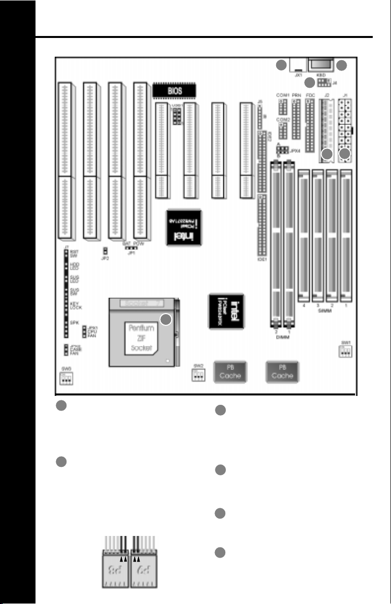
MAINBOARD DIAGRAM.....................................................................
• Board Layout • Glossary of Board Components
INST ALLA TION GUIDE......................................................................
• Step-by-Step Installation Procedures
CONNECTOR PIN CONFIGURA TIONS...........................................
• AT Power Supply Connector • Keyboard Connector • Infrared Module
Connector • Universal Serial Bus Connector
CASE SWITCH PIN CONFIGURATIONS..........................................
• Reset Switch Connector • HDD LED Connector • Suspend LED Connector
• Suspend Switch Connector • Keylock & Power LED Connector • Speaker
Connector • Case Fan Connector
MISCELLANEOUS PIN CONFIGURA TIONS...................................
• CMOS RAM Discharge Selector • CPU Fan Connector • DIMM Voltage
Selector • CPU External Clock Selector • CPU Core Voltage Selector • CPU
Clock Multiplier Selector
CPU CONFIGURA TION JUMPERS..................................................
• CPU Configuration Jumpers Chart
MEMORY CONFIGURA TIONS..........................................................
• Memory Installation • Memory Considerations
A TX POWER FEA TURES...................................................................
• ATX Power Supply Connector Pinouts • Power Switch • Modem Ring
Power-On • RTC Soft Power-On • Windows 95 Shut Down
BIOS OVERVIEW AND SPECIFICA TIONS.......................................
• Warning • Installing a New Bios • Entering the WinBios Setup • Default
Settings
STANDARD AND ADV ANCED BIOS SETTINGS.............................
• Primary Master & Slave, Secondary Master & Slave • Floppy Drive A & B •
1st 2nd 3rd 4th Boot Device • SMART for Hard Disks • Quick Boot • PS/2
Mouse Support • Password Check • Internal Cache • External Cache
POWER, PCI/PnP & PERIPHERAL BIOS SETTINGS....................
• Power Management/APM • Green PC Monitor Power States • Video
Power Down Mode • Plug and Play Aware OS • Offboard PCI IDE Card • PCI
Slot 1/2/3/4 IRQ Priority • IRQ 4, 5, 7, 9, 10, 11, 12, 14, 15 • Onboard FDC •
Onboard Serial Port 1 & 2 • Onboard Parallel Port, Mode & IRQ • Onboard
IDE
HELPFUL HINTS AND TROUBLESHOOTING TIPS......................
• What To Do First... • If You Are Still Having Problems...
3
4
5
6
7
8
9
10
11
12
13
14
15

PM-9800 MAINBOARD MANUAL
CPUs SUPPORTED
•Intel
®
Pentium
®
P54C (75MHz to 200MHz)
•Intel
®
Pentium
®
with MMX™ T echnology P55C (166MHz to 233MHz)
•Cyrix
®
/IBM
®
6x86MX (PR166)
•Cyrix
®
/IBM
®
6x86L (PR166+)
•Cyrix
®
/IBM
®
6x86 (PR120+ to PR200+)
•AMD™ K6 (PR2-166 to PR2-233)
•AMD™ K5 (PR75 to PR166)
•IDT WinChip C6™ (200MHz)
•High Performance Intel
®
430TX Chipset
•Switching voltage regulator supports 3.5, 3.3, 3.2, 3.0, 2.9, 2.8 & 2.5 volt processors
MEMORY
•Up to 256MB of main memory in 4 (2 banks) auto banking 72-pin SIMM slots for Fast
Page Mode or EDO DRAM, and 2 168-pin DIMM sockets for SDRAM, Fast Page Mode
DRAM, or EDO DRAM modules.
•Supports 64M-bit (16M X 4, 8M X 8, 4M X 16) technology DRAM/SDRAM
CACHE
•On-Board 512KB Pipeline Burst Cache
•Up to 64MB Cacheable Main Memory Size
ENHANCED IDE CONTROLLER
•Two PCI EIDE Interfaces for up to four EIDE devices in two channels. Individually supports
PIO Mode 0 to 4 and Ultra DMA/33 for all four devices - all four devices may have different
PIO modes and performance will be optimized for each device
BUS ARCHITECTURE
•Four 32-bit PCI Local Bus Slots with Master Mode
•Four 16-bit ISA Bus Slots
•Compliant to PCI 2.1
ON-BOARD I/O CONTROLLER
•On-Board Interfaces for High Speed Multi-I/Os
•Two 16550 Fast Serial Ports
•One SPP, EPP & ECP Mode Capable Parallel Port
•One High Speed Floppy Drive Connector
(Supports 2.88MB floppy drives & 1Mb/sec floppy transfer rates)
•One PS/2-type Mouse Header.
POWER MANAGEMENT FEATURES
•SMM/SMI Power Management with APM Software Interface - Monitor CPU and I/O status
with fully user configurable parameters in BIOS
•Supports following ATX power functions: Power Switch, Modem Ring-On, RTC Soft-On
•Advanced Configuration Power Interface
BIOS FEATURES
•AMI “Plug and Play” Flash ROM for easy BIOS upgrades
3
MAINBOARD SPECIFICATIONS
PM-9800 MAINBOARD MANUAL
4
MAINBOARD DIAGRAM
A
B
C
D
E
A
ZIF SOCKET
Plug the processor into this socket.
Make sure the cpu is correctly aligned
before you insert it.
A T POWER SUPPLY
CONNECTOR
Plug the dual connectors from the
power supply directly into the board
connectors. On most power supplies,
you must orient the black (ground)
wires such that all the black wires on
both connectors are in the middle.
B
C
A TX POWER SUPPLY
CONNECTOR
Plug the single 20 pin connector into
the board connector. It should only fit
in one direction.
A T STYLE KEYBOARD
CONNECTOR
Plug a standard 5-pin female DIN key-
board connector into this port.
PS/2 MOUSE CONNECTOR
Plug a PS/2 mouse connector into
this port.
PS/2 MOUSE HEADER
Use this when you want to relocate
the PS/2 mouse connector plug off the
mainboard
D
F
E
F

PM-9800 MAINBOARD MANUAL
BE SURE YOU KNOW WHA T YOU ARE DOING!
•It’s easy to get overly excited about your purchase, and to jump right into installing the
system board into your case. T oo many times, people fail to read the manual or insist on
installing it themselves, only to find out later that they’ve permanently damaged their
motherboard and as well as their components. Though this manual will make installation
seem like a fairly simple procedure, it is not. So, if you’re not a technophile or have little
or no computer knowledge, consider asking your vendor or a trained technician to install
this board.
SET SW1, SW2, SW3 TO CONFIGURE THE BOARD FOR YOUR CPU
•It’s fairly easy to forget a jumper or two, so before you power on your system, make sure
to check & double check your settings so that you don’t prematurely burn out your CPU.
INSERT THE CPU INTO THE ZIF SOCKET
•Pull up the handle and insert the CPU with the dotted corner aligned with the corner of the
ZIF socket that looks like its missing a pinhole. Plug it in and pull down on the handle.
INSTALL YOUR MEMORY INTO THE CORRECT SOCKETS
•Insert your memory into the corresponding DIMM or SIMM sockets. Follow the instruc-
tions outlined in the memory section of this manual.
INST ALL THE MAINBOARD ONT O THE SYSTEM CHASSIS
•Make sure the mainboard is properly grounded and mounted into the case. T ake time to
do this properly as it makes the installation of your cards and cables easier.
CONNECT AND INST ALL YOUR CARDS & I/O CABLES
•Be sure your cables and cards are properly oriented and plugged in firmly. See the helpful
hint page for tips on connecting your i/o cables.
CONNECT YOUR CASE LED & SWITCH CABLES TO THE BOARD
CONNECT THE POWER SUPPLY CABLES TO THE BOARD
•See the mainboard diagram page for tips on connecting your power cables.
POWER ON AND GO INTO BIOS AND SETUP YOUR SYSTEM
•Press <del> during memory check phase of POST and see the BIOS setup pages of this
manual for more details on setting up your system’s configuration. If you get a blank
screen, refer to the troubleshooting section for some tips on solving this problem.
GET YOUR OPERATING SYSTEM UP AND RUNNING
•Bootup your OS and see if the board and all your peripherals are recognized and working.
CLOSE UP YOUR CASE
5
INSTALLATION GUIDE
 Loading...