


 Loading...
CoreModule 420
PC/104 Single Board Computer
Reference Manual
P/N 5001692A Revision A

Notice Page
NOTICE
No part of this document may be reproduced, transmitted, transcribed, stored in a retrieval system, or translated into any language or computer language, in any form or by any means, electronic, mechanical, magnetic, optical, chemical, manual, or otherwise, without the prior written permission of Ampro Computers, Incorporated.
DISCLAIMER
Ampro Computers, Incorporated makes no representations or warranties with respect to the contents of this manual or of the associated Ampro products, and specifically disclaims any implied warranties of merchantability or fitness for any particular purpose. Ampro shall under no circumstances be liable for incidental or consequential damages or related expenses resulting from the use of this product, even if it has been notified of the possibility of such damages. Ampro reserves the right to revise this publication from time to time without obligation to notify any person of such revisions. If errors are found, please contact Ampro at the address listed below on the Notice page of this document.
TRADEMARKS
Ampro and the Ampro logo are registered trademarks, and CoreModule, EnCore, Little Board, LittleBoard, MiniModule, and ReadyBoard are trademarks of Ampro Computers, Inc. All other marks are the property of their respective companies.
REVISION HISTORY
Revision |
Reason for Change |
Date |
|
|
|
A |
Initial Release |
Mar/04 |
|
|
|
|
|
|
|
|
|
|
|
|
|
|
|
|
|
|
Ampro Computers, Incorporated 5215 Hellyer Avenue
San Jose, CA 95138-1007 Tel: 408 360-0200
Fax: 408 360-0222 www.ampro.com
© Copyright 2004, Ampro Computers, Incorporated
Audience Assumptions
This reference manual is for the person who designs computer related equipment, including but not limited to hardware and software design and implementation of the same. Ampro Computers, Inc. assumes you are qualified in designing and implementing your hardware designs and its related software into your prototype computer equipment.
ii |
Reference Manual |
CoreModule 420 |

Contents |
|
|
Chapter 1 |
About This Manual ......................................................................................................... |
1 |
Purpose of this Manual....................................................................................................................... |
1 |
|
Reference Material ............................................................................................................................. |
1 |
|
Related Ampro Products .................................................................................................................... |
2 |
|
Chapter 2 |
Product Overview........................................................................................................... |
5 |
PC/104 Architecture............................................................................................................................ |
5 |
|
Product Description ............................................................................................................................ |
6 |
|
Module Features ............................................................................................................................ |
6 |
|
Block Diagram ................................................................................................................................ |
9 |
|
Major Integrated Circuits (ICs) ..................................................................................................... |
10 |
|
Connectors, Jumpers, and LEDs...................................................................................................... |
11 |
|
Connector Definitions ................................................................................................................... |
11 |
|
Jumper Definitions........................................................................................................................ |
12 |
|
LED Definitions............................................................................................................................. |
12 |
|
Specifications.................................................................................................................................... |
14 |
|
Physical Specifications................................................................................................................. |
14 |
|
Mechanical Specifications ............................................................................................................ |
14 |
|
Power Specifications .................................................................................................................... |
15 |
|
Environmental Specifications ....................................................................................................... |
15 |
|
Thermal/Cooling Requirements.................................................................................................... |
15 |
|
Chapter 3 |
Hardware....................................................................................................................... |
17 |
Overview |
....................................................................................................................................... |
17 |
CPU (U14) |
....................................................................................................................................... |
18 |
Memory |
....................................................................................................................................... |
18 |
SDRAM Memory (U7, U8, U9, U10)............................................................................................. |
18 |
|
Flash Memory (U6)....................................................................................................................... |
18 |
|
Bytewide Socket (U5)................................................................................................................... |
18 |
|
Memory Map................................................................................................................................. |
18 |
|
Interrupt Channel Assignments.................................................................................................... |
20 |
|
I/O Address Map........................................................................................................................... |
20 |
|
PC/104 Bus Interface (P1A,B,C,D)................................................................................................... |
22 |
|
IDE Interface (J6).............................................................................................................................. |
27 |
|
CompactFlash Socket (J12) ............................................................................................................. |
29 |
|
Floppy/Parallel Port (J4) ................................................................................................................... |
31 |
|
Floppy Disk Drive Port.................................................................................................................. |
31 |
|
Parallel Port.................................................................................................................................. |
31 |
|
Serial Ports (J3, J9, J13, J14) .......................................................................................................... |
33 |
|
USB Port (J10).................................................................................................................................. |
35 |
|
Utility Interface (J5)........................................................................................................................... |
36 |
|
Keyboard ...................................................................................................................................... |
36 |
|
Mouse |
....................................................................................................................................... |
36 |
Battery |
....................................................................................................................................... |
36 |
Reset Switch................................................................................................................................. |
36 |
|
Speaker |
....................................................................................................................................... |
36 |
Ethernet Interface (J2)...................................................................................................................... |
37 |
|
Video (LCD/CRT) Interface (J11) ..................................................................................................... |
38 |
|
CoreModule 420 |
Reference Manual |
iii |

Contents |
|
|
Miscellaneous................................................................................................................................... |
40 |
|
Real Time Clock (RTC)................................................................................................................ |
40 |
|
User GPIO Signals....................................................................................................................... |
40 |
|
Oops! Jumper (BIOS Recovery) .................................................................................................. |
41 |
|
Serial Console.............................................................................................................................. |
41 |
|
Watchdog Timer........................................................................................................................... |
42 |
|
Power Interface (J7)......................................................................................................................... |
43 |
|
Chapter 4 |
BIOS Setup ................................................................................................................... |
45 |
Introduction....................................................................................................................................... |
45 |
|
Accessing BIOS Setup (VGA Display)......................................................................................... |
45 |
|
Accessing BIOS Setup (Serial Console)...................................................................................... |
46 |
|
Main BIOS Setup Menu ................................................................................................................... |
47 |
|
BIOS Configuration Screen.............................................................................................................. |
48 |
|
Splash Screen Customization.......................................................................................................... |
53 |
|
Splash Screen Image Requirements ........................................................................................... |
53 |
|
Converting the Splash Screen File .............................................................................................. |
53 |
|
On-Board Flash Access and Use..................................................................................................... |
55 |
|
Flash Programming Requirements .............................................................................................. |
55 |
|
Building the Example ................................................................................................................... |
55 |
|
Example Assumptions ................................................................................................................. |
56 |
|
Installing the Example Application ............................................................................................... |
56 |
|
Flash Boot API ............................................................................................................................. |
56 |
|
Appendix A |
Technical Support ....................................................................................................... |
57 |
Appendix B Connector Part Numbers ............................................................................................ |
59 |
|
Index |
....................................................................................................................................... |
61 |
List of Figures |
|
|
Figure 2-1. |
Stacking PC/104 Modules with the CoreModule 420..................................................... |
5 |
Figure 2-2. CoreModule 420 Block Diagram..................................................................................... |
9 |
|
Figure 2-3. CoreModule 420 (Top View)......................................................................................... |
10 |
|
Figure 2-4. |
Connector Locations (Top View) .................................................................................. |
11 |
Figure 2-5. Jumper and LED Locations (Top View)........................................................................ |
13 |
|
Figure 2-6. |
Connector Location (Bottom View)............................................................................... |
13 |
Figure 2-7. |
Mechanical Dimensions (Top View) ............................................................................. |
14 |
Figure 3-1. |
Serial 1 to RS485 Conversion ...................................................................................... |
33 |
Figure 3-2. Oops! Jumper ............................................................................................................... |
41 |
|
Figure 3-3. Hot Cable Jumper......................................................................................................... |
42 |
|
Figure 4-1. BIOS Setup Opening Screen........................................................................................ |
47 |
|
Figure 4-2. |
BIOS Configuration Screen .......................................................................................... |
48 |
List of Tables |
|
|
Table 2-1. |
Major Integrated Circuit Descriptions and Function....................................................... |
10 |
Table 2-2. |
Module Connector Descriptions..................................................................................... |
11 |
Table 2-3. |
Jumper Settings ............................................................................................................. |
12 |
Table 2-4. |
Ethernet Port (J2) LED Indicators.................................................................................. |
12 |
Table 2-5. Weight and Footprint Dimensions.................................................................................. |
14 |
|
Table 2-6. Power Supply Requirements ......................................................................................... |
15 |
|
Table 2-7. |
Environmental Requirements ........................................................................................ |
15 |
iv |
Reference Manual |
CoreModule 420 |

|
|
Contents |
Table 3-1. Memory Map .................................................................................................................. |
18 |
|
Table 3-2. |
Interrupt Channel Assignments...................................................................................... |
20 |
Table 3-3. DMA Map........................................................................................................................ |
20 |
|
Table 3-4. |
I/O Address Map ............................................................................................................ |
20 |
Table 3-5. |
PC/104 Bus Interface Pin/Signal Descriptions (P1A)..................................................... |
22 |
Table 3-6. |
PC/104 Bus Interface Pin/Signal Descriptions (P1B)..................................................... |
23 |
Table 3-7. |
PC/104 Bus Interface Pin/Signal Descriptions (P1C) .................................................... |
24 |
Table 3-8. |
PC/104 Bus Interface Pin/Signal Descriptions (P1D) .................................................... |
25 |
Table 3-9. |
IDE Interface Pin/Signal Descriptions (J6) ..................................................................... |
27 |
Table 3-10. |
CompactFlash Interface Pin/Signal Descriptions (J12)................................................ |
29 |
Table 3-11. |
Parallel Interface (SPP) Pin/Signal Descriptions (J4) .................................................. |
31 |
Table 3-12. |
Serial Ports Pin/Signal Descriptions (J3, J9)................................................................ |
34 |
Table 3-13. |
Serial 3 & 4 Interface Pins/Signals (J13, J14).............................................................. |
34 |
Table 3-14. |
USB Interface Pin and Signal Designations (J10) ....................................................... |
35 |
Table 3-15. |
Utility Interface Pin/Signal Descriptions (J5) ................................................................ |
36 |
Table 3-16. |
Ethernet Interface Pin/Signal Descriptions (J2) ........................................................... |
37 |
Table 3-17. |
Video Interface Pin/Signal Descriptions (J11).............................................................. |
39 |
Table 3-18. |
User GPIO Signals Pin/Signal Descriptions (J8) ......................................................... |
41 |
Table 3-19. |
Power Interface Pins/Signals (J7) ................................................................................ |
43 |
Table 3-20. |
Power Interface Pin Arrangement (J7)......................................................................... |
43 |
Table 4-1. BIOS Setup Menus......................................................................................................... |
46 |
|
Table A-1. |
USA Technical Support Contact Information................................................................. |
57 |
Table B-1. |
Connector and Manufacture’s Part Numbers ................................................................ |
59 |
CoreModule 420 |
Reference Manual |
v |

Contents
vi |
Reference Manual |
CoreModule 420 |

Chapter 1 About This Manual
Purpose of this Manual
This manual is for designers of systems based on the CoreModule™ 420 PC/104 single board computer (SBC) module. This manual contains information that permits designers to create an embedded system based on specific design requirements.
Information provided in this reference manual includes:
•CoreModule 420 SBC Specifications
•Environmental requirements
•Major chips and features implemented
•CoreModule 420 SBC connector/pin numbers and definition
•BIOS Setup information
Information not provided in this reference manual includes:
•Detailed chip specifications
•Internal component operation
•Internal registers or signal operations
•Bus or signal timing for industry standard busses and signals
Reference Material
The following list of reference materials may be helpful for you to complete your custom design successfully. Most of this reference material is also available on the Ampro web site in the Embedded Design Resource Center. The Embedded Design Resource Center was created for embedded system developers to share Ampro’s knowledge, insight, and expertise gained from years of experience.
Specifications
•PC/104 Specifications Revision 2.5, November 2003.
For latest revision of the PC/104 specifications, contact the PC/104 Consortium, at: Web site: http://www.pc104.org
Chip Specifications
The following chip specifications are used in the CoreModule 420 processor module:
•STMicroelectronics and the chip, STPC® Atlas, used for the embedded CPU Web site: http://us.st.com/stonline/books/pdf/docs/7341.pdf
•Standard Microsystems Corp and the chip, FDC37B782, used for the Super I/O controller Web site: http://www.smsc.com/main/catalog/fdc37b78x.html
•Intel Corporation and the chip, 82551ER, used for the Ethernet controller
Web site: http://www.intel.com/design/network/products/lan/controllers/82551er.html
CoreModule 420 |
Reference Manual |
1 |

Chapter 1 |
About this Manual |
Related Ampro Products
The following items are directly related to successfully using the Ampro product you have just purchased or plan to purchase. Ampro highly recommends that you purchase and utilize a CoreModule 420 QuickStart Kit simultaneously with the design of your product.
CoreModule 420 Support Products
•CoreModule 420 QuickStart Kit (QSK)
The CoreModule 420 QuickStart Kit includes the CoreModule 420 CPU, a complete cable kit, documentation, and drivers for any Ampro supported operating systems with unique devices used on the board.
•CoreModule 420 Development System
The CoreModule 420 Development System is a benchtop system, which provides a “known good” environment for your development work. The Development System provides an integrated and easy-to-use self-hosted development environment that lets you maximize the benefit of using off-the-shelf PC-compatible modules as the basis of your embedded system design. You can install PC/104 expansion modules or ISA bus expansion boards on the Development System chassis. The Development System is laid out to make all the components of your system accessible. Refer to the CoreModule 420 Development System Users Guide on the CoreModule 420 Documentation and Support Software (Doc & SW) CD-ROM for more information.
•CoreModule 420 Documentation and Support Software CD-ROM
The CoreModule 420 Documentation and Support Software (Doc & SW) CD-ROM is provided with the CoreModule 420 QuickStart Kit and the Development System. The CD-ROM includes all of the CoreModule documentation, including this Reference Manual, the CoreModule 420 QuickStart Guide, and the CoreModule 420 Development System Users Guide in PDF format, release notes, software utilities, and drivers.
Other CoreModule Products
• |
CoreModule |
410 – This PC/104 embedded CPU is a state-of-the-art, high-integration x86- |
|
based computer using STMicroelectronics' 133MHz STPC Elite processor, which provides a |
|
|
complete embedded PC solution with most of the standard peripheral interfaces. In addition to |
|
|
the standard CoreModule features (PC/104 form factor, PC/104 bus, +5 volt power, etc.), it |
|
|
includes 16MB soldered SDRAM memory, watchdog timer, serial console, BIOS extensions for |
|
|
OEM boot customization, and Advanced Power Management. The CoreModule 410 also offers a |
|
|
Bytewide socket supporting DiskOnChip 2000 devices and a GPIO interface for customer usage. |
|
• |
CoreModule |
600 – This PC/104-Plus embedded single board computer (SBC) is a compact, |
|
rugged, high integration, ultra low power 400MHz ULV Celeron processor with 256kB of |
|
|
internal cache, and all of the standard peripheral interfaces. In addition to the standard |
|
|
CoreModule features (PC/104 form factor, PC/104-Plus, +5 volt power, etc.), the CoreModule |
|
|
600 includes 10/100BaseT Ethernet, AGP 4X video with 32MB video memory for CRT, TFT and |
|
|
standard LCD flat panels, USB ports, RS232C/RS485 serial ports, and an onboard Type II |
|
|
CompactFlash socket, which supports up to 1GB or more of flash memory. The CoreModule 600 |
|
|
also supports a watchdog timer, serial console, battery-less boot, BIOS extensions for OEM boot |
|
|
customization, some power management features and up to 256MB of SDRAM memory. |
|
Other Ampro Products |
||
• |
LittleBoard |
Family – These high-performance, highly integrated single board computers use |
|
the EBX form factor (5.75x8.00 inches), and are available with Pentium MMX, Pentium III, and |
|
|
Celeron processors. The EBX-compliant LittleBoard single board computers offer functions |
|
|
equivalent to a complete laptop or desktop PC system, plus several expansion cards. Built-in |
|
extras to meet the critical requirements of embedded applications include onboard solid state disk capability, watchdog timer, smart power monitor, and other embedded-PC BIOS enhancements.
2 |
Reference Manual |
CoreModule 420 |

Chapter 1 |
About this Manual |
• |
MiniModule Family – This extensive line of peripheral interface modules, compliant with |
|
PC/104 and PC/104-Plus standard, can be used with Ampro’s CoreModule and LittleBoard single |
|
board computers to configure embedded system solutions. Ampro's highly reliable MiniModule |
|
products currently support USB 2.0, IEEE 1394 (FireWire), CRT and flat panel display |
|
interfaces, Ethernet, PC Card expansion, analog/data acquisition, FPGA, additional |
|
RS232/RS485 serial ports, and general-purpose I/O (GPIO). |
• |
EnCore Family – These high-performance, compact, modular CPU solutions use various |
|
processor technologies including Intel x86, MIPS, and PowerPC architectures to plug into your |
|
custom logic board. Each EnCore module provides standard peripherals, including IDE, floppy |
|
drive interface, PCI bus, serial, parallel, PS/2 keyboard and mouse interfaces, 10/100BaseT |
|
Ethernet, and USB ports. Some EnCore modules also provide video and AC97 sound. |
|
Depending on the model, EnCore modules can hold between 16MB and 512MB of SODIMM |
|
SDRAM memory. |
CoreModule 420 |
Reference Manual |
3 |

Chapter 1 |
About this Manual |
4 |
Reference Manual |
CoreModule 420 |
Chapter 2 Product Overview
This introduction presents general information about the PC/104 architecture and the CoreModule 420 single board computer (SBC). After reading this chapter you should understand:
•PC/104 Concept
•CoreModule 420 architecture
•CoreModule 420 features
•Major components
•Connectors
•Specifications
PC/104 Architecture
The PC/104 architecture affords a great deal of flexibility in system design. You can build a simple system using only a CoreModule 420, with input/output devices connected to its serial or parallel ports, and a solid state disk drive or CompactFlash card in the respective bytewide socket, or CompactFlash socket. To expand a simple CoreModule system, simply add self-stacking Ampro MiniModules or 3rd party PC/104 expansion boards to provide additional capabilities, such as:
•Additional serial and parallel ports
•Analog or digital I/O
•PCMCIA interfaces
•Sound cards
PC/104 expansion modules can be stacked with the CoreModule 420 avoiding the need for card cages and backplanes. The PC/104 expansion modules can be mounted directly to the PC/104 bus connector of the CoreModule 420. PC/104-compliant modules can be stacked with an inter-board spacing of ~0.66 inches so that a 3-module system fits in a 3.6 inch by 3.8 inch by 2.4 inch space. See Figure 2-1.
One or more MiniModule products or other PC/104 modules can be installed on the CoreModule expansion connectors. When installed on P1 and P2, the expansion modules fit within the CoreModule outline dimensions. Most MiniModule products have stack through connectors compatible with the PC/104 Version 2.5 specification. Several modules can be stacked on the CoreModule headers. Each additional module increases the thickness of the package by 15mm (0.60”). See Figure 2-1.
4-40 nut (4) |
|
|
|
|
|
PC/104 Module |
|
|
|
|
|
|
|
|
|
|
|
|||||
|
|
|
|
|
|
|
|
|
|
|
|
|
|
|
|
|
|
|
|
|
|
|
|
|
|
|
|
|
|
|
|
|
|
|
|
|
|
|
|
|
|
|
|
|
|
0.6 inch spacer (4) |
|
|
|
|
|
|
|
|
|
|
|
|
|
|
|
|
|
|
|
|
|
|
|
|
|
|
|
CoreModule 420 |
|
|
|
|
|
|
|
|
|
|
|
||||||
|
|
|
|
|
|
|
|
|
|
|
|
|
|
|
|
|||||||
|
|
|
|
|
|
|
|
|
|
|
|
|
|
|
|
|||||||
|
|
|
|
|
|
|
|
|
|
|
|
|
|
|
|
|||||||
|
|
|
|
|
|
|
|
|
|
|
|
|
|
|
||||||||
|
|
|
|
|
|
|
|
|
|
|
|
|
|
|
|
|
||||||
|
|
|
|
|
|
|
|
|
|
|
|
|
|
|
|
|
|
|
|
|
|
Stackthrough |
|
|
|
|
|
|
|
|
|
|
|
|
|
|
|
|
|
|
|
|
|
|
|
|
|
|
|
|
|
|
PC/104 Module |
|
|
|
|
|
|
|
|
|
Expansion |
|||||
0.6 inch spacer (4) |
|
|
|
|
|
PC/104 Module |
|
|
|
|
|
|
|
|
|
|
|
Bus Headers |
||||
|
|
|
|
|
|
|
|
|
|
|
|
|
|
|
|
|||||||
|
|
|
|
|
|
|
|
|
|
|
|
|
|
|
|
CM420stack |
||||||
|
|
|
|
|
|
|
|
|
|
|
|
|
|
|||||||||
|
|
|
|
|
|
|
|
|
|
|
|
|
|
|
||||||||
4-40 screw (4) |
|
|
|
|
|
|
|
|
|
|
|
|
|
|
|
|
||||||
|
|
|
|
|
|
|
|
|
|
|
|
|
||||||||||
|
|
|
|
|
|
|
|
|
|
|
|
|
|
|
|
|
|
|
|
|
||
|
|
|
|
|
|
|
|
|
|
|
|
|
|
|
|
|
|
|
|
|
||
|
|
|
|
|
|
|
|
|
|
|
|
|
|
|
|
|
|
|
|
|
||
|
|
|
|
|
|
|
|
|
|
|
|
|
|
|
|
|
|
|
|
|
|
|
|
|
|
|
|
|
|
|
|
|
|
|
|
|
|
|
|
|
|
|
|
||
|
|
|
|
|
|
|
|
|
|
|
|
|
|
|
|
|
|
|
|
|
|
|
|
|
|
|
|
|
|
|
|
|
|
|
|
|
|
|
|
|
|
|
|
|
|
Figure 2-1. Stacking PC/104 Modules with the CoreModule 420
CoreModule 420 |
Reference Manual |
5 |

Chapter 2 |
Product Overview |
Product Description
The CoreModule 420 SBC is an exceptionally high integration, high-performance, 486-based PC compatible system in the PC/104 form factor. This rugged and high quality single board system contains all the component subsystems of a PC/AT motherboard plus the equivalent of several PC/AT expansion boards.
In addition, the CoreModule 420 SBC includes a comprehensive set of system extensions and enhancements that are specifically designed for embedded systems. These enhancements ensure failsafe embedded system operation, such as, a watchdog timer. It is designed to meet the size, power consumption, temperature range, quality, and reliability demands of embedded applications. The CoreModule 420 requires a single +5V power source.
The CoreModule 420 SBC is particularly well suited to either embedded or portable applications. Its flexibility makes system design quick and easy. It can be stacked with Ampro MiniModules or other PC/104-compliant expansion, or it can be used as the computing engine in a fully customized application.
Module Features
•CPU
♦Supports 133MHz x86 based STPC ATLAS microprocessor
♦Fully PC compatible architecture
♦8kB Unified Instruction and Data Cache
♦Parallel Processing Integrated Floating Point Unit
♦Low Power and System Management Modes
•Memory
♦64MB standard SDRAM (soldered on the board)
♦100MHz Clock Speed
♦32-pin bytewide memory socket
•Supports a DiskOnChip® device
♦1MB Flash memory
•Stores system BIOS
•Stores system Setup parameters and manufacturing information
•Supports battery-free boot capability
•768kB available for OEM use
•PC/104 Bus Interface
♦Clock speeds up to 8.25MHz
•IDE Interface
♦Supports two enhanced IDE devices
♦Fast ATA-capable interface supports high-speed PIO modes (PIO modes 0 to 4)
♦Supports ATAPI and DVD peripherals
♦Supports IDE native and ATA compatibility modes
6 |
Reference Manual |
CoreModule 420 |

Chapter 2 |
Product Overview |
•CompactFlash Socket
♦Supports Type II PC card connector
♦Supports IDE CompactFlash card
♦Utilizes Secondary IDE bus
•Floppy Disk Controller
♦Shared connector with parallel port
♦Supports two floppy drives
♦Supports all standard PC/AT formats: 360kB, 1.2MB, 720kB, 1.44MB, 2.88MB
•Serial Ports
♦Four buffered RS232 serial ports with full handshaking and modem capability
♦Provides 16550 or 15540-equivalent controllers, each with a built-in 16-byte FIFO buffer
♦Ports 1 and 2 support RS232 or RS485 operation
♦Supports programmable word length, stop bits, and parity
♦Supports 16-bit programmable baud-rate generator and a interrupt generator
•Parallel Port
♦Shared connector with Floppy drive port
♦Supports standard printer port
♦Supports IEEE standard 1284 protocols, including EPP, ECP modes
♦Bidirectional data lines
♦Supports 16 byte FIFO for ECP mode
•Ethernet Controller
♦Intel 82551ER Controller chip
♦Supports IEEE 802.3 10BaseT/100BaseT compatible physical layer
♦Supports Auto-negotiation for speed, duplex mode, and flow control
♦Supports full duplex or half-duplex mode
•Full-duplex mode supports transmit and receive frames simultaneously
•Supports IEEE 802.3x Flow control in full duplex mode
•Half-duplex mode supports enhanced proprietary collision reduction mode
•Utility Interface
♦Keyboard and PS/2 Mouse Interface
♦Supports external battery for Real Time Clock operation
♦ Supports standard 8Ω speaker interface
♦Supports a Reset switch
•USB Ports
♦Supports one root USB hub
♦Supports one USB port
♦Supports USB v1.1 and Universal OHCI v1.1
CoreModule 420 |
Reference Manual |
7 |

Chapter 2 |
Product Overview |
•Video (LCD/CRT) Display
Enhanced 2D graphics controller
♦Supports BitBLT implementation for all 256 raster operations for Window support
♦Supports all BLT transparency modes
•Bitmap transparency
•Pattern transparency
•Source transparency
•Destination transparency
♦Supports 8, 16, 24, and 32-bit pixel depths
♦Supports Hardware Clipping
♦Supports fast line draw engine with Anti-aliasing
♦Supports fast triangle fill engine
♦Supports 4-bit Alpha blend font for Anti-aliased text display
♦Supports 64-bit wide Pipelined architecture operating at 100MHz
♦Supports complete double buffered registers for pipelined operation
♦Supports video memory up to 4MB – selected in BIOS Setup
CRT
♦VGA Controller with 135MHz triple RAMDACs for 1280 x 1024 x 75Hz display
♦Supports 24-bit pixel depth
♦Interlaced or non-interlaced output
LCD/TFT Controller
♦Supports VESA Flat Panel Display interface FPDI-1B
♦Supports programmable panel size up to 1024x768 pixel display resolution
♦Supports VGA and SVGA active matrix TFT flat panels
♦Support internal CRT controller for display mode settings
♦Supports 9-, 12-, and 18-bit interface (1 Pixel/Clock)
♦Supports 2x9-bit interface (2 Pixels/Clock)
♦Supports programmable image position
♦Supports 3.3V or 5V LCD panels; jumper selectable
♦Video BIOS customization tools provided
•Miscellaneous
♦Battery-backed real-time clock and CMOS RAM, with support for battery-free operation
♦General Purpose I/O (GPIO)
♦Oops! Jumper (BIOS Recovery)
♦Serial Console (or Console Redirection)
♦Watchdog Timer
8 |
Reference Manual |
CoreModule 420 |
Chapter 2 |
Product Overview |
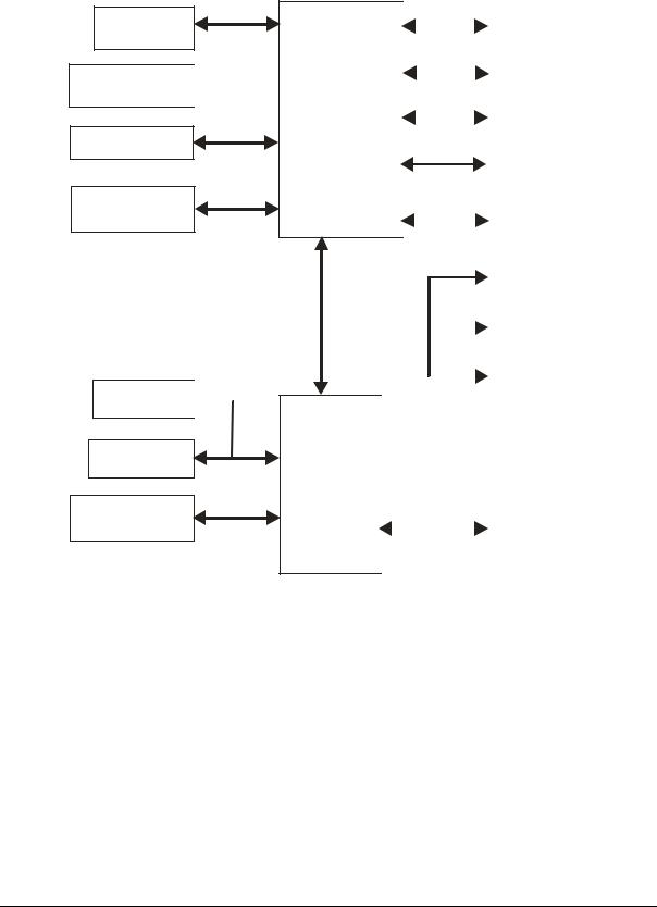
Block Diagram
Figure 2-2 shows the functional components of the module.
Memory (SDRAM)
Video (CRT/TFT) 

Speaker
Serial Ports (Serial 1 & 2)
Floppy Drive 
Parallel Port
Serial Ports (Serial 3 & 4)
|
|
|
|
|
|
Internal PCI |
|
|
|
|
|
|
|
||||
|
|
|
|
|
|
Bus |
|
|
|
|
|
|
|
||||
|
CPU |
|
|
Ethernet |
|
|
|
|
|
|
|||||||
|
|
|
|
|
|
|
|
|
|||||||||
|
|
|
|
|
|
|
|
Controller |
|
|
|
|
|
|
|||
|
Core |
|
|
|
|
|
|
|
|
||||||||
|
|
|
|
|
|
|
|
|
|
|
|
|
|
|
|||
STPC Atlas |
|
|
|
|
|
|
|
I2C Interface |
|
|
|
|
|||||
|
|
|
|
|
|
|
|
|
|
|
|
||||||
(Computer |
|
|
|
|
|
|
|
|
|
|
|
|
|
|
|||
in a Chip) |
|
|
|
|
|
|
|
|
|
|
|
|
|
|
|||
|
|
|
|
|
|
|
|
|
|
|
|
|
|
||||
|
|
|
|
|
|
|
|
|
|
|
USB Port |
|
|
|
|
|
|
|
|
|
|
|
|
|
|
|
|
|
|
|
|
|
|
|
|
|
|
|
|
|
|
|
|
|
|
|
|
|
|
|
|
|
|
|
|
|
|
|
|
|
|
|
|
|
|
|
|
|
|
|
|
|
|
|
|
|
|
|
|
|
|
|
|
|
|
|
|
||
Host- |
|
|
|
|
|
GPIOs (8) |
|
|
|
|
|
|
|||||
Peripheral |
|
|
|
|
|
|
|
|
|
|
|
|
|||||
|
|
|
|
|
|
|
|
|
|
|
|
||||||
Interface |
|
|
|
|
|
|
|
|
|
|
|
|
|||||
|
|
|
|
|
IDE Devices |
|
|||||||||||
|
|
|
|
|
|
|
|
|
|
|
(HDD, CompactFlash, |
|
|||||
|
|
|
|
|
|
|
|
|
|
|
|
||||||
|
|
|
|
|
|
|
|
|
|
|
CD-ROM, etc.) |
|
|||||
|
|
|
|
|
|
|
|
|
|
|
|
||||||
|
|
|
|
|
|
|
|
|
|
|
|
|
|
|
|||
|
|
|
|
|
|
|
|
|
|
|
PC/104 Interface |
||||||
|
|
ISA Bus |
|
|
|
|
|
|
|
|
|
|
|
|
|||
|
|
|
|
|
|
|
|
|
|
|
|
|
|
||||
|
|
|
|
|
|
|
DiskOnChip |
|
|
|
|
||||||
|
|
|
|
|
|
|
|
|
|
|
|
|
|||||
|
|
|
|
|
|
|
|
|
|
|
|
|
|
|
|||
|
|
|
|
|
|
|
|
|
|
|
|
|
|
||||
|
|
|
|
|
|
|
|
|
|
|
BIOS |
|
|||||
|
|
|
|
|
|
|
|
|
|
|
|||||||
|
|
|
|
|
|
|
|
|
|
|
|
|
|
|
|
||
|
|
|
|
|
|
|
|
|
|
|
|
|
|
|
|
|
|
|
|
RTC |
|
|
|
|
|
|
|
|
|
|
|
|
|
CM420blkdiag |
|
|
|
|
|
|
|
|
|
|
|
|
|
|
|
|
|||
Super I/O |
|
|
|
|
|
|
|
|
|
|
|
|
|
||||
Controller |
|
|
|
|
|
|
|
|
|
|
|
|
|
|
|||
|
|
|
|
|
|
|
|
|
|
|
|
|
|
|
|
||
|
|
|
|
|
|
|
|
|
|
|
Utility Interface |
|
|
||||
|
|
|
|
|
|
|
|
|
|
|
(Keyboard, Mouse, |
|
|||||
|
|
|
|
|
|
|
|
|
|
|
|
|
|||||
|
|
|
|
|
|
|
|
|
|
|
External Bat. etc) |
|
|||||
|
|
|
|
|
|
|
|
|
|
|
|
|
|
|
|
|
|
|
|
|
|
|
|
|
|
|
|
|
|
|
|
|
|
|
|
Figure 2-2. CoreModule 420 Block Diagram
CoreModule 420 |
Reference Manual |
9 |

Chapter 2 |
Product Overview |
Major Integrated Circuits (ICs)
Table 2-1 lists the major integrated circuits, including a brief description of each, on the CoreModule 420 and Figure 2-3 shows the location of the major chips.
Table 2-1. Major Integrated Circuit Descriptions and Function
Chip Type |
Mfg. |
Model |
Description |
Function |
CPU (U14) |
STMicro- |
STPC |
Embedded CPU – The combination of |
Embedded |
|
electronics |
ATLAS |
features in the CPU provide more than |
CPU |
|
|
|
just a processor. It also provides a |
|
|
|
|
graphics controller, PCI controller, |
|
|
|
|
EIDE controller, I/O features, and |
|
|
|
|
power management capabilities. |
|
Super I/O |
Standard |
FDC37B782 |
Super I/O – This chip provides serial |
Floppy/Serial |
Controller (U13) |
Microsystems |
|
and Floppy controllers |
Controllers |
|
Corp. |
|
|
|
Ethernet |
Intel |
82551ER |
Ethernet – This chip provides the |
Ethernet |
Controller (U15) |
|
|
10/100BaseT Ethernet function. |
|
CPU (U14)
Super I/O (U13)
|
2 |
|
|
|
|
J5 |
JP1 |
|
|
1 |
|
|
|
|
|
|
|
|
JP6 |
9 |
|
J14 |
4 |
2 |
J3 |
|
|
D8 |
10 |
|
10 |
3 |
1 |
|
|
|
|
JP7 |
|
J13 |
JP5 JP4 |
|
|
|
|
|
|
|
U36 |
U35 |
|
|
|
J9 |
U12 |
L5 |
|
U3 |
|
|
||
J11 |
JP9 |
|
J4 |
|
||||
|
1J8 |
|
||||||
|
|
|
|
|
|
|
|
|
|
|
|
JP8 |
|
2 |
|
Flash |
|
|
|
|
U7 |
U8 |
U9 |
U10 |
U6 |
Memory (U6) |
|
U11 |
|
|
|||||
|
|
|
|
|
|
|
|
|
U40 |
U41 |
U5 |
|
|
|
|
D1 |
D2 |
U14 |
U15 |
J2 |
|
|
U13
 J10
J10
U16 |
J7 |
P1 |
JP2 |
Figure 2-3. CoreModule 420 (Top View)
SDRAM Memory (U7-U10)
Ethernet
Controller (U15)
Ethernet
Magnetics (U16)
CM420RFM_01a
NOTE |
Pin 1 is shown as black square or round black pin in |
|
connectors and jumpers in all illustrations. |
|
|
10 |
Reference Manual |
CoreModule 420 |

Chapter 2 |
Product Overview |
Connectors, Jumpers, and LEDs
Connector Definitions
Table 2-2 describes the connectors shown in Figures 2-4 to 2-6. Refer to Appendix B for part #s.
Table 2-2. Module Connector Descriptions
Jack/Plug # |
Access |
Description |
||
P1A/1B & P1C/1D – |
Top/ |
104-pin connector used for PC/104 (ISA) bus |
||
|
|
PC/104 Bus |
Bottom |
|
J2 |
– Ethernet |
Top |
8-pin, 0.1”, connector used for the Ethernet interface |
|
|
|
|
|
|
J3 |
– Serial 1 (COM1) |
Top |
10-pin, 0.1”, connector used for the Serial 1 interface |
|
|
|
|
|
|
J4 |
– Floppy/Parallel |
Top |
26-pin, 0.1”, connector provides the Floppy/Parallel interface |
|
|
|
|
|
|
J5 |
– Utility |
Top |
10-pin, 0.1”, connector used for the Utility interface |
|
|
|
|
|
|
J6 |
– IDE |
Top |
44-pin, 2mm connector used for the IDE interface |
|
|
|
|
|
|
J7 |
– Power |
Top |
10-pin, 0.1”, connector used for the Power connection |
|
|
|
|
|
|
J8 |
– GPIO (User) |
Top |
10-pin, 2mm connector used for the User defined GPIO signals |
|
|
|
|
|
|
J9 |
– Serial 2 (COM2) |
Top |
10-pin, 0.1”, connector used for the Serial 2 interface |
|
|
|
|
|
|
J10 |
– USB |
Top |
5-pin, 0.1”, connector used for the USB interface |
|
|
|
|
|
|
J11 |
– Video |
Top |
44-pin, 2mm connector used for the LCD/CRT interface |
|
|
|
|
|
|
J12 |
– CompactFlash |
Bottom |
50-pin connector used for CompactFlash cards |
|
|
|
|
|
|
J13 |
– Serial 3 (COM3) |
Top |
10-pin, 0.1”, connector used for the Serial 3 interface |
|
|
|
|
|
|
J14 |
– Serial 4 (COM4) |
Top |
10-pin, 0.1”, connector used for the Serial 4 interface |
|
|
|
|
|
|
IDE (J6)
Serial 4 (J14)
(COM 4)
Serial 2 (J9) |
J9 |
(COM 2) |
J11 |
|
2
1
JP6 |
9 |
J14 |
|
10 |
10 |
D8 |
|
JP7 |
|
|
|
U12 |
L5 |
U3 |
JP9 |
||
|
|
JP8 |

 U7 U8 U11
|
J5 |
JP1 |
4 |
2 |
J3 |
3 |
1 |
|
J13 JP5 |
JP4 |
|
U36 |
U35 |
|
|
1 |
J4 |
|
2J8 |
|
U9 |
U10 |
U6 |
Video (J11) |
U40 |
U41 |
U5 |
|
D2 |
||
|
|
D1 |
U14 |
U15 |
J2 |
|
|
|
U13 |
|
|
J10
U16 |
USB (J10)
J7 |
P1 |
JP2 |
Power (J7) |
|
|
Utility (J5)
Serial 1 (J3) (COM 1)
Serial 3 (J13) (COM 3)
GPIO (J8)
Floppy/Parallel (J4)
Ethernet (J2)
P1B |
_01b |
|
CM420RFM |
||
P1C |
||
P1A |
|
|
P1D |
|
|
(PC104 Bus) |
|
Figure 2-4. Connector Locations (Top View)
CoreModule 420 |
Reference Manual |
11 |

Chapter 2 |
Product Overview |
Jumper Definitions
Table 2-3 describes the jumpers shown in Figure 2-5.
Table 2-3. Jumper Settings
Jumper # |
|
Installed |
Removed |
|||
JP1 Serial Port 1 |
Enable RS485 Termination |
Disable RS485 Termination |
||||
Termination |
(Pins 1-2) |
(No jumper) Default setting |
||||
JP2 Serial Port 2 |
Enable RS485 Termination |
Disable RS485 Termination |
||||
Termination |
(Pins 1-2) |
(No jumper) Default setting |
||||
JP4 & JP5 |
|
Enable Internal BIOS – Normal operation, |
Disabled – Won’t Boot |
|||
BIOS/DOC Select |
(Pins 1-3 on both JP4 & JP5) |
(See other positions) |
||||
JP5 JP4 |
Enable External BIOS – Used for recovery |
Disabled – Won’t Boot |
||||
4 |
|
2 4 |
|
2 |
(Pins 1-2 on both JP4 & JP5) |
(See other positions) |
|
|
|||||
3 |
|
1 |
|
1 |
||
|
|
|||||
BIOS/DOC Select |
Enable DOC – Boot from DiskOnChip in |
Disabled – Won’t Boot |
||||
Jumper Setting |
bytewide socket (Pins 1-3 & 2-4 on both |
(See other positions) |
||||
(Shown in Default) |
||||||
|
|
|
|
|
JP4 & JP5) Default setting |
|
JP6 |
|
|
|
+3.3 Volts (Pins 1-2) |
+5 Volts (Pins 2-3) |
|
Flat Panel Voltage |
|
|
||||
Selection |
|
|
|
|||
JP7 |
|
|
|
Access from DC000h-DDFFFh |
Access from CC000h-CDFFFh |
|
DiskOnChip Boot |
(Pins 1-2) |
(No jumper) |
||||
Address Select |
|
|
||||
JP8 Serial Port 1 |
Enable Serial Port 1 |
Disabled Serial Port 1 |
||||
|
|
|
|
|
(Pins 1-2) Default setting |
(Pins 2-3) |
JP9 Serial Port 2 |
Enable Serial Port 2 |
Disabled Serial Port 2 |
||||
|
|
|
|
|
(Pins 1-2) Default setting |
(Pins 2-3) |
Note: JP8 and JP9 Enable/Disable the Serial ports at the STPC Altas CPU (U14).
LED Definitions
Table 2-4 provides the LED color and definitions for the Ethernet Port (J2) located on the CoreModule 420 and Figure 2-5 provides the locations.
Table 2-4. Ethernet Port (J2) LED Indicators
Indicator |
Definition |
Ethernet |
Link/Activity LED – This yellow LED is the activity/link |
Link/Activity LED (D1) |
indicator and provides the status of Ethernet port (J2). |
|
The Link/Activity LED indicates an Link is established with |
|
either transmit or receive activity. |
|
Yellow On – This indicates a link is present. |
|
Yellow Flashing – This indicates activity is present. |
|
Yellow Off – This indicates no link or activity is present. |
|
|
Ethernet Speed (D2) |
Speed LED – This green LED is the LAN Speed indictor and |
|
indicates the transmit or receive speed of Ethernet port (J2). |
|
Green On – This indicates the operating speed is 100Mbps |
|
Green Off – This indicates the operating speed is 10Mbps. |
12 |
Reference Manual |
CoreModule 420 |

Chapter 2 |
|
|
|
|
Product Overview |
JP6 JP9 |
JP7 |
JP8 |
JP5 |
JP4 |
JP1 |
2 |
|
|
|
J5 |
JP1 |
1 |
|
|
|
|
|
JP6 |
9 |
J14 |
4 |
2 |
J3 |
J9
J11
D8
 U12
U12

10 |
|
10 |
|
|
JP7 |
L5 |
|
U3 |
|
|
|
|
JP9 |
JP8 |
|
|
3 |
1 |
J13 |
JP5 JP4 |
U36 |
U35 |
|
|
1 |
J4 |
|
2J8 |
|
|
|
|
|
|
Bytewide |
|
U7 U8 |
U9 U10 |
U6 |
|
Socket (U5) |
|
U11 |
|
|
|
Pin-1 |
|
|
|
|
|
|
U40 |
U41 |
|
U5 |
|
|
|
|
|
|
|
|
|
|
|
D1 |
D2 |
Link/Activity |
|
|
|
|
|
|
|
|
U14 |
U15 |
J2 |
LED (D1) |
|
|
|
Speed |
||
|
U13 |
|
|
|
|
J10 |
|
|
|
|
LED (D2) |
U16 |
|
|
|
|
01c |
J7 |
P1 |
JP2 |
JP2 |
CM420RFM_ |
|
||||
|
|
|
|
Figure 2-5. Jumper and LED Locations (Top View)
Voltage |
|
D4 |
D3 |
|
|
CompactFlash |
Regulator |
|
|
|
|||
|
|
|
|
|
Socket (J12) |
|
(U19) |
U19 |
|
|
|
|
|
|
|
|
|
|
||
|
|
U1 |
|
|
|
|
|
|
|
|
|
|
|
|
U37 |
|
|
|
U21 |
|
|
U20 |
|
|
|
D5 |
|
|
|
|
|
|
|
|
|
U22 |
|
U24 |
|
|
|
|
U23 |
|
|
|
U42 |
|
|
|
|
|
|
|
|
|
|
|
J12 |
|
|
F1 |
|
|
|
U25 |
Y3 |
|
USB Fuse (F1) |
|
|
|
|
Y2 |
||
|
U29 |
U38 Y1 |
|
U27 |
U28 |
U30 |
|
|
PC/104 Bus (P1) |
|
|
CM420RFM 02a |
|
|
|
|
|
|
||
|
|
Figure 2-6. Connector Location (Bottom View) |
||||
CoreModule 420 |
Reference Manual |
13 |

Chapter 2 |
Product Overview |
Specifications
Physical Specifications
Table 2-5 gives the physical dimensions of the module and Figure 2-7 gives the mounting dimensions.
Table 2-5. Weight and Footprint Dimensions
Item |
Dimension |
|
|
|
Weight |
92.5g. (0.204lbs.) |
|
NOTE |
Height is measured from the |
|
|
upper surface of the board |
||
|
|
|
||
Height (upper surface) |
10.99 mm (0.43 inches) |
|
|
to the highest permanent |
|
See also Note on page 15. |
|
|
component on the upper |
|
|
|
|
surface of the board. |
Width |
90.2 mm (3.6 inches) |
|
|
|
|
|
|
||
|
|
|
||
Length |
95.9 mm (3.8 inches ) |
|
|
|
|
|
|
||
Mechanical Specifications
|
|
0.000 |
0.150 |
0.400 |
|
|
|
1.160 |
1.800 |
2.100 |
|
2.375 |
|
3.050 |
3.105 |
|
3.575 |
|
|
|
|
|
|
|
|
|
|
|
|
|
|
|
|
3.431 |
|
|
|
|
|
|
|
|
|
|
|
|
|
|
JP1 |
3.400 |
3.375 |
|
|
|
|
J6 |
|
|
|
|
|
|
|
J5 |
|
|
3.375 |
|
|
|
|
JP6 |
9 |
|
|
|
4 |
|
2 |
|
|
3.190 |
||
|
|
|
|
|
|
10 |
|
10 |
|
3 |
|
1 |
|
|
|
|
|
|
J9 |
|
|
|
|
|
|
|
|
|
|||||
3.281 |
|
|
|
|
|
J14 |
J13 |
JP5 |
JP4 |
|
|
J3 |
|
|
||
2.890 |
|
|
|
|
|
|
|
JP7 |
|
|
|
|
|
|
|
|
|
|
|
|
|
|
|
|
|
|
|
|
|
|
|
|
|
|
|
|
|
|
|
|
JP9 |
JP8 |
|
|
|
|
|
|
|
3.100 |
|
|
|
|
|
|
|
|
|
1 |
|
|
|
|
2.500 |
||
2.580 |
|
|
|
|
|
|
|
|
|
|
2J8 |
|
|
|
|
|
|
J11 |
|
|
|
|
|
|
|
|
|
|
|
|
|
||
|
|
|
|
|
|
|
|
|
|
|
|
|
|
|
||
|
|
|
|
|
|
|
|
|
|
|
|
|
|
J4 |
|
|
|
|
|
|
|
|
|
|
|
CPU |
|
|
|
|
|
|
01d |
|
|
|
|
|
|
|
|
|
|
|
|
|
|
|
CM420RFM_ |
|
0.940 |
|
|
|
|
|
|
|
|
U14 |
|
|
|
P1B |
J2 |
|
|
0.700 |
|
|
|
|
|
|
|
|
|
|
|
|
|
|
|
|
|
J10 |
|
|
|
|
|
|
|
|
|
P1A |
|
|
|
||
|
|
|
|
|
|
|
|
|
|
|
P1C |
|
|
|
||
|
|
|
|
|
|
|
|
|
|
|
|
|
P1D |
|
|
0.394 |
0.300 |
|
|
|
|
|
|
|
|
|
|
|
|
|
|
|
|
|
|
|
|
|
|
|
|
|
|
|
|
|
|
|
|
|
0.000 |
|
|
|
|
|
|
|
|
|
|
|
|
|
|
|
0.000 |
-0.010 |
|
|
|
|
|
|
J7 |
|
|
|
|
|
|
JP2 |
|
|
-0.200 |
|
|
|
|
|
|
|
|
|
|
|
|
|
|
|
|
|
|
|
|
|
|
|
|
|
|
|
|
|
|
|
|
|
-0.200 |
-0.030 |
-0.020 0.000 |
0.050 |
0.280 |
|
|
0.850 |
|
|
|
|
|
|
3.112 |
3.150 |
3.350 |
Figure 2-7. Mechanical Dimensions (Top View)
NOTE |
All dimensions are given in inches. Pin 1 is shown as a black square or black |
|
round pin in connectors and jumpers in all illustrations. |
|
|
14 |
Reference Manual |
CoreModule 420 |
Chapter 2 Product Overview
NOTE |
The CoreModule 420 is in violation of the PC/104 height limitations in two |
|
places on the bottom of the board. The voltage regulator (U19) exceeds the |
|
allowed height limitation by 0.085 inches and the CompactFlash socket (J12) |
|
exceeds the height limitation by 0.2 inches. See Figure 2-6. |
|
|
Power Specifications
Table 2-6 provides the power requirements.
Table 2-6. Power Supply Requirements
Parameter |
Characteristics |
Input Type |
Regulated DC voltages |
|
|
Input Voltage |
+5 VDC +/- 5% @ 1.35 Amps (typical) |
Requirements |
|
Operating Power |
6.75 Watts (typical) |
|
|
Note: Current readings were taken with all peripheral devices connected or simulated using the Windows 2000 operating system.
Environmental Specifications
Table 2-7 provides the most efficient operating and storage condition ranges required for this module.
Table 2-7. Environmental Requirements
Parameter |
Conditions |
Temperature |
|
|
|
Operating |
+0° to +70° C (32° to 158° F) |
|
|
Extended (Optional) |
–40° to +85° C (–40° F to +185° F) |
|
|
Storage |
–55° to +85° C (–67° F to +185° F) |
|
|
Humidity |
|
|
|
Operating |
20% to 80% relative humidity, non-condensing |
|
|
Non-operating |
5% to 95% relative humidity, non-condensing |
|
|
Thermal/Cooling Requirements
The CPU requires a heatsink (provided).
CoreModule 420 |
Reference Manual |
15 |

Chapter 2 |
Product Overview |
16 |
Reference Manual |
CoreModule 420 |
Loading...