

Page 1

Page 2

TMA10A
Anemometer
User Manual
• Mode d’emploi
• Bedienungshandbuch
• Manuale d’Uso
• Manual de uso
PN 2099394
March 2007
©2007 Amprobe Test Tools.
All rights reserved. Printed in China
Page 3

Page 4

TMA10A
Anemometer
User Manual
• Mode d’emploi
• Bedienungshandbuch
• Manuale d’Uso
• Manual de uso
English
Page 5

Limited Warranty and Limitation of Liability
Your Amprobe product will be free from defects in material and workmanship for 1
year from the date of purchase. This warranty does not cover fuses, disposable
batteries or damage from accident, neglect, misuse, alteration, contamination, or
abnormal conditions of operation or handling. Resellers are not authorized to
extend any other warranty on Amprobe’s behalf. To obtain service during the
warranty period, return the product with proof of purchase to an authorized
Amprobe Test Tools Service Center or to an Amprobe dealer or distributor. See
Repair Section for details. THIS WARRANTY IS YOUR ONLY REMEDY. ALL OTHER
WARRANTIES - WHETHER EXPRESS, IMPLIED OR STAUTORY - INCLUDING
IMPLIED WARRANTIES OF FITNESS FOR A PARTICULAR PURPOSE OR
MERCHANTABILITY, ARE HEREBY DISCLAIMED. MANUFACTURER SHALL NOT BE
LIABLE FOR ANY SPECIAL, INDIRECT, INCIDENTAL OR CONSEQUENTIAL
DAMAGES OR LOSSES, ARISING FROM ANY CAUSE OR THEORY. Since some
states or countries do not allow the exclusion or limitation of an implied warranty or
of incidental or consequential damages, this limitation of liability may not apply to
you.
Page 6

TMA10A Anemometer/Thermometer
Contents
Using the Pushbuttons .......................................................................................2
Display Indicators ...............................................................................................3
Making Measurements........................................................................................4
Air Velocity Measurements ..............................................................................4
Air Flow Measurements ...................................................................................4
Single Point MIN/MAX/AVG Recording............................................................5
Multi Point Average Recording ........................................................................5
Data Hold Feature ............................................................................................6
Changing the Units of Measure........................................................................6
Auto Power Off ...................................................................................................7
Error Message Display........................................................................................7
Useful Equations and Conversions......................................................................7
Cubic Equations...............................................................................................7
Units Conversion Table ....................................................................................7
Replacing the Battery..........................................................................................7
Repair .................................................................................................................7
Specifications .....................................................................................................9
1
Page 7

Using the Pushbuttons
ON/ OFF MODE HOLD
VELOCITY
FREE AREA
VOLUMES
AVERAGE
MIN MAX
For Operation
MULTIPOINT
SINGLE
POINT
Please See Manual
ANEMOMETER THERMOMETER
Button Description
ON/OFF
MODE
HOLD
MIN MAX
AVERAGE
Turns the meter on and off.
Toggle between velocity, free area, and volume.
Captures a reading. Sets digit to the desired value.
View the minimum or maximum. Average or record value.
Display the average of all the measurements. Select the next
digit for editing.
2
Page 8

Display Indicators
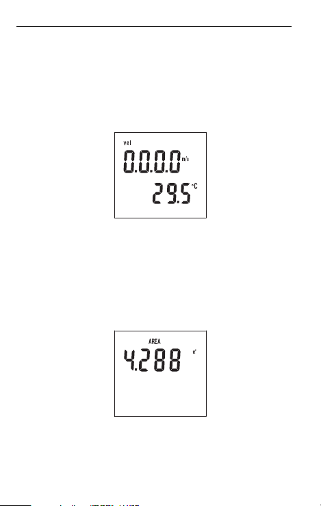
Vel Air velocity measurement.
FLOW Air flow/air volumen.
AREA Free area default setting.
Hold Freezes the reading.
knots 1850 meters per hour.
ft/m Feet per minute.
ft2 Square feet.
m/s Meters per second.
m2 Square meters.
mil/h Miles per hour.
cfm Cubic feet per minute.
km/h Kilometers per hour.
cms Cubic meters per second.
Primary display Numerical display for air velocity, air volume, and
free area digit.
°C Celsius units.
°F Fahrenheit units.
Secondary display Temperature display or record number.
MIN Minimum data.
MAX Maximum data.
REC Record and saved.
AVG Average data.
- Polarity indicator for negative temperature.
3
Page 9
Making Measurements
Air Velocity Measurements
Air velocity and temperature measurements can be displayed on this meter in the
following units of measure: ft/m (feet per minute) or m/s (meters per second) for
air velocity and °F or °C for temperature.
1. Connect the sensor to the sensor input jack on top of the meter.
2. Turn on the meter using the ON/OFF button.
3. The 'Vel' indicator should appear on the upper left on the LCD. If not, press and
hold the MODE button until a beep is heard. Repeat this procedure until 'Vel'
appears on the display.
4. Place the sensor in the air current to be measured.
5. View the air velocity and temperature readings on the LCD Display. The upper
display shows the air velocity reading. The lower display shows the
temperature.
Air Flow Measurements
In order to take air flow measurements, the area of the duct under test (in ft2 or m2)
must first be determined (check with the duct manufacturer if necessary). Once the
area is known, enter the value as follows:
1. Turn on the meter with the ON/OFF button.
2. Press and hold the MODE button until a beep is heard. “AREA” appears on the
display and one digit will be blinking indicating that value can be changed.
3. Press the HOLD button to adjust the digit to the value needed.
4. Press the AVERAGE button to select the next digit for editing.
5. When the area is correctly entered, press the MIN MAX button once. A beep will
sound and the digits will stop blinking.
6. Press the HOLD button once to store the area value.
4
Page 10

7. The meter is now ready to measure air flow. Place the sensor in the air current
and view the air flow and temperature readings on the LCD.
Single Point MIN/MAX/AVG Recording
This meter can record and display the lowest (MIN), highest (MAX), and average
(AVG) air velocity, air flow, and temperature readings.
1. Follow the instructions for starting air velocity or air flow measurements
detailed on the previous page.
2. Press the MIN MAX button. The REC and AVG (average) indicators will appear
on the display and the meter will begin recording data.
3. When the measurement session is complete (up to 2 hours maximum), press
the HOLD button until the beep sounds.
4. To view the MIN reading, press the MIN MAX button twice or until the MIN
indicator appears. The minimum reading will be displayed on the LCD.
5. Press MIN MAX again to view the maximum value, the MAX indicator along
with the maximum reading will appear on the LCD display.
6. Press MIN MAX again to view the averaged value, the AVG indicator along with
the average reading will appear on the LCD display.
7. To exit this mode, press and hold the MIN MAX button until 2 beeps are heard
in rapid succession and the display indicators (REC, MIN, MAX, AVG)
disappear.
Multi Point Average Recording
The meter can take up to 8 separate measurements and average them
automatically.
1. Follow the instructions for starting air velocity or air flow measurements
detailed on the previous page.
2. When the first measurement is taken and is on the display, press and hold the
HOLD button. Release the button when the tone is heard.
3. The reading will hold and the 'HOLD' icon will appear above it on the LCD.
4. Press and hold the MIN MAX button until a tone is heard then release it. The
LCD will briefly indicate a number (1 through 8) representing the current
measurement number.
5
Page 11

5. Repeat this process until up to 8 measurements have been taken.
6. Press the AVERAGE button to display the average of all the measurements.
7. To exit this mode, press and hold the MIN MAX button until 2 beeps are heard
in rapid succession and the display indicators (REC, MIN, MAX, AVG)
disappear.
Data Hold Feature
1. While taking measurements you can freeze the displayed reading by pressing
and holding the HOLD button until a beep is heard.
2. The 'HOLD' indicator will appear on the LCD when the display is in this mode.
3. Press and hold the HOLD button until a beep is heard to exit this mode.
Changing the Units of Measure
U.S. units of measure are °F, ft/m (feet per minute), and CFM (cubic feet per
minute). Metric units are: °C, m/s (meters per second), and CMS (cubic meters per
second).
1. Turn the meter on by pressing and holding both the ON/OFF and the AVERAGE
buttons simultaneously. Release the ON/OFF button first then release the
AVERAGE button. The units of measure will appear on the LCD.
2. Press the HOLD button to select Metric and the AVERAGE button to select U.S.
3. Press the MIN MAX button and an "S" will appear on the LCD.
4. Press the HOLD button to advance to the next selection.
5. The baud rate for PC Interface models will appear (1200 or 2400). Select the
baud rate, if necessary, by pressing the HOLD (1200) or AVERAGE (2400)
button.
6. To return to normal operation, press MIN MAX again (the "S" will reappear) then
press and hold the HOLD button until the beep is heard.
6
Page 12

Auto Power Off
The TMA10A Anemometer turns off automatically after 20 minutes to conserve
battery power. Press the ON/OFF and HOLD buttons to disable the Auto Power Off
feature.
Error Message Display
If the sensor is not connected to the meter or if the sensor is inoperable, the meter
beeps, the error message "E6" appears on the display, and the meter shuts down.
Connect the sensor or return the meter and sensor for repair.
Useful Equations and Conversions
Cubic Equations
CFM (ft3/min) = Air Velocity (ft/min) x Area (ft2)
CMS (m3/sec) = Air Velocity (m/sec) x Area (m2)
Units Conversion Table
m/s ft/min knots km/h MPH
1 m/s 1 196.87 1.944 3.6 2.24
1 ft/min 0.00508 1 0.00987 0.01829 0.01138
1 knot 0.5144 101.27 1 1.8519 1.1523
1 km/h 0.2778 54.69 0.54 1 0.6222
1 MPH 0.4464 87.89 0.8679 1.6071 1
Replacing the Battery
Replace the 9 V battery when the display is flashing or there is no display.
1. Remove the Phillips head screw on the battery compartment cover.
2. Lift off the rear battery compartment cover.
3. Replace the 9 V battery and secure the battery compartment cover.
Repair
All test tools returned for warranty or non-warranty repair or for calibration should
be accompanied by the following: your name, company’s name, address, telephone
number, and proof of purchase. Additionally, please include a brief description of
the problem or the service requested and include the test leads with the meter.
Non-warranty repair or replacement charges should be remitted in the form of a
check, a money order, credit card with expiration date, or a purchase order made
payable to Amprobe® Test Tools.
7
Page 13

In-Warranty Repairs and Replacement – All Countries
Please read the warranty statement and check your battery before requesting repair.
During the warranty period any defective test tool can be returned to your
Amprobe® Test Tools distributor for an exchange for the same or like product.
Please check the “Where to Buy” section on www.amprobe.com for a list of
distributors near you. Additionally, in the United States and Canada In-Warranty
repair and replacement units can also be sent to a Amprobe® Test Tools Service
Center.
Non-Warranty Repairs and Replacement – US and Canada
Non-warranty repairs in the United States and Canada should be sent to a
Amprobe® Test Tools Service Center. Call Amprobe® Test Tools or inquire at your
point of purchase for current repair and replacement rates.
In USA In Canada
Amprobe Test Tools Amprobe Test Tools
Everett, WA 98203 Mississauga, ON L4Z 1X9
Tel: 877-AMPROBE (267-7623) Tel: 905-890-7600
Non-Warranty Repairs and Replacement – Europe
European non-warranty units can be replaced by your Amprobe® Test Tools
distributor for a nominal charge. Please check the “Where to Buy” section on
www.amprobe.com for a list of distributors near you.
European Correspondence Address*
Amprobe® Test Tools Europe
P.O. Box 1186
5602 BD Eindhoven
The Netherlands
*(Correspondence only – no repair or replacement available from this address.
European customers please contact your distributor.)
8
Page 14

Specifications
Display Dual 4-digit (9999 count) LCD
Measurement units
Data hold Freezes displayed reading
Sensors
MIN MAX Memory
Average reading memory
Automatic Power off
Operating Temperature 32 °F to 122 °F (0°C to 50 °C)
Operating Humidity Max. 80% RH
Power Supply
Weight 0.8 lb (363 g) including battery and sensor
Dimensions
Air Velocity: ft/min (feet per minute); m/s
(meters per second)
Air Flow: CMS (m3/sec) and CFM (ft3/min);
Temp: °C and °F
Air velocity/flow sensor: Conventional angled
vane arms with low-friction ball bearing. Temp.
sensor: Precision thermistor
Record and view minimum and maximum
readings
Single Point (up to 2 hours) or Multi-Point (up
to 8 readings)
Sleep mode (with bypass) after 20 mins.
conserves energy
9 V battery (Heavy duty alkaline); Battery life:
100 hours
Main instrument: 7.1 x 2.8 x 1.4 in (181 x 71 x
38 mm)
Sensor head diameter: 70 mm
Air Velocity
Measurements Range
m/s (meters per
sec)
ft/min (feet per
minute)
Air Flow
Measurements Range
CMS (cubic meters
per sec.)
CFM (cubic feet
per minute)
Air Temperature Range Resolution Accuracy
0.40 to 25.00 m/s 0.01 m/s ±2% of full scale
125 to 4900 ft/min 1 ft/min ±2% of full scale
0.01 to 99.99 m3/sec 0.01 0 to 9.999 m2
1 to 9999 ft3/min 1.0 0 to 9.999 ft2
32 to 122 °F (0 to 50 °C) 0.1 °F/°C ±1.5 °F (0.8 °C)
Resolution Accuracy
Resolution Area
9
Page 15

10
Page 16

TMA10A
Anemometer
User Manual
• Mode d’emploi
• Bedienungshandbuch
• Manuale d’Uso
• Manual de uso
Français
French
Page 17

Limites de garantie et de responsabilité
Amprobe garantit l’absence de vices de matériaux et de fabrication de ce produit
dans des conditions normales d’utilisation et d’entretien pendant une période d’un
an prenant effet à la date d’achat. Cette garantie ne s’applique pas aux fusibles, aux
piles jetables ni à tout produit mal utilisé, modifié, contaminé, négligé ou
endommagé par accident ou soumis à des conditions anormales d’utilisation et de
manipulation. Les distributeurs agréés par Amprobe ne sont pas autorisés à
appliquer une garantie plus étendue au nom de Amprobe. Pour bénéficier de la
garantie, renvoyez le produit accompagné d’un justificatif d’achat auprès d’un
centre de services agréé par Amprobe Test ou du distributeur ou du revendeur
Amprobe. Voir la section Réparation ci-dessus pour tous les détails. LA PRESENTE
GARANTIE EST LE SEUL ET EXCLUSIF RECOURS TOUTES AUTRES GARANTIES,
EXPLICITES, IMPLICITES OU STATUTAIRES, NOTAMMENT LE CAS ECHEANT LES
GARANTIES DE QUALITE MARCHANDE OU D’ADAPTATION A UN OBJECTIF
PARTICULIER SONT EXCLUES PAR LES PRESENTES. LE FABRICANT NE SERA EN
AUCUN CAS TENU RESPONSABLE DE DOMMAGES PARTICULIERS, INDIRECTS,
ACCIDENTELS OU CONSECUTIFS, NI D’AUCUNS DEGATS OU PERTES DE
DONNEES, SUR UNE BASE CONTRACTUELLE, EXTRA-CONTRACTUELLE OU
AUTRE. Etant donné que certains pays ou états n’admettent pas les limitations
d’une condition de garantie implicite, ou l’exclusion ou la limitation de dégâts
accidentels ou consécutifs, les limitations et les exclusions de cette garantie ne
s’appliquent pas obligatoirement à chaque acheteur.
Page 18

Thermomètre/anémomètre TMA10A
Table des matières
Utilisation des boutons poussoirs.......................................................................2
Indicateurs..........................................................................................................3
Opérations de mesure.........................................................................................4
Mesures de la vitesse de l’air ...........................................................................4
Mesures du débit d’air .....................................................................................4
Enregistrement de valeurs monopoints MIN/MAX/AVG ...................................5
Enregistrement de valeurs moyennes multipoints ...........................................5
Fonction de maintien des données...................................................................6
Modification des unités de mesure ..................................................................6
Arrêt automatique ...............................................................................................7
Affichage du message d’erreur ...........................................................................7
Equations et conversions utiles ..........................................................................7
Equations cubiques..........................................................................................7
Tableau de conversion des unités ....................................................................7
Remplacement de la pile.....................................................................................7
Réparation ..........................................................................................................8
Caractéristiques ..................................................................................................9
1
Page 19

Utilisation des boutons poussoirs
ON/ OFF MODE HOLD
VELOCITY
FREE AREA
MIN MAX
VOLUMES
AVERAGE
For Operation
MULTIPOINT
SINGLE
POINT
Please See Manual
ANEMOMETER THERMOMETER
Bouton Description
ON/OFF
MODE
HOLD
MIN MAX
AVERAGE
Active ou désactive l’appareil.
Permet de basculer entre la vitesse, la section libre et le
volume.
Saisit une valeur. Règle les chiffres sur la valeur souhaitée.
Affiche le minimum ou le maximum. Affiche la moyenne ou
enregistre la valeur.
Affiche la moyenne de toutes les mesures. Sélectionne le chiffre
suivant à modifier.
2
Page 20

Indicateurs
Vel Mesure la vitesse de l’air.
FLOW Volume/débit d’air.
AREA Réglage par défaut de la section libre.
Hold Fige la valeur affichée.
Knots 1850 mètres par heure (nœuds).
ft/m Pieds par minute.
ft2 Pieds carrés.
m/s Mètres par seconde.
m2 Mètres carrés.
mil/h Miles par heure.
cfm Pieds cubes par minute.
km/h Kilomètres par heure.
cms Mètres cubes par seconde.
Affichage principal Affichage numérique de la vitesse de l’air, du
volume d’air et de la section libre.
°C Degrés celsius.
°F Degrés fahrenheit.
Affichage secondaire Affichage de la température ou numéro de
l’enregistrement.
MIN Valeur minimum.
MAX Valeur maximum.
REC Enregistrer et sauvegardé.
AVG Valeur moyenne.
- Indicateur de polarité pour la température négative.
3
Page 21

Opérations de mesure
Mesures de la vitesse de l’air
Les mesures de température et de vitesse de l’air sont affichées sur cet appareil
dans les unités de mesure suivantes : ft/m (pieds par minute) ou m/s (mètres par
seconde) pour la vitesse de l’air et degrés °F ou °C pour les températures.
1. Branchez le capteur à la prise d’entrée du capteur au sommet de l’appareil.
2. Mettez l’appareil sous tension en utilisant le bouton ON/OFF.
3. L’indicateur « Vel » doit apparaître dans le coin supérieur gauche de l’écran
LCD. Sinon, maintenez le bouton MODE enfoncé jusqu’au retentissement du bip
sonore. Répétez cette procédure jusqu’à l’apparition de l’indicateur « Vel » sur
l’écran.
4. Placez le capteur dans le courant d’air à mesurer.
5. Affichez la vitesse de l’air et les valeurs de température sur l’écran LCD.
L’affichage supérieur affiche la mesure de la vitesse de l’air. L’affichage inférieur
indique la température obtenue.
Mesures du débit d’air
Pour relever des mesures du débit d’air, déterminez d’abord la section du conduit
testé (en m2 ou en ft2) (consultez le fabricant du conduit si nécessaire). Une fois
cette section connue, entrez la valeur comme suit :
1. Mettez l’appareil sous tension à l’aide du bouton ON/OFF.
2. Maintenez le bouton MODE enfoncé jusqu’au retentissement du bip sonore. Le
mot « AREA » s’affiche et un chiffre se met à clignoter pour indiquer que cette
valeur peut être modifiée.
3. Maintenez le bouton HOLD pour ajuster le chiffre sur la valeur nécessaire.
4. Appuyez sur le bouton AVERAGE pour sélectionner le chiffre suivant à modifier.
5. Une fois la section correctement saisie, appuyez une fois sur le bouton
MIN MAX. Un bip retentit et les chiffres s’arrêtent de clignoter.
4
Page 22

6. Appuyez sur le bouton HOLD pour stocker la valeur de la section.
7. L’appareil est maintenant prêt à mesurer le débit d’air. Placez le capteur dans le courant
d’air et observez le débit d’air et les températures relevées sur l’écran LCD.
Enregistrement de valeurs monopoints MIN/MAX/AVG
Cet appareil peut enregistrer et afficher les valeurs minimales (MIN), maximales
(Max) et moyennes (AVG) des températures, du débit et de la vitesse de l’air.
1. Suivez les instructions pour effectuer les mesures du débit d’air ou de la vitesse
de l’air détaillées sur la page précédente.
2. Appuyez sur le bouton MIN MAX. Les indicateurs REC et AVG (moyenne)
apparaissent sur l’affichage et l’appareil enregistre les résultats.
3. Lorsque la séance de mesure est terminée (durée de 2 heures maximum),
appuyez sur le bouton HOLD jusqu’à l’émission du bip sonore.
4. Pour afficher la valeur MIN, appuyez deux fois sur le bouton MIN MAX ou
jusqu’à l’apparition de l’indicateur MIN. La valeur minimale apparaît sur l’écran
LCD.
5. Appuyez de nouveau sur MIN MAX pour afficher la valeur maximale ;
l’indicateur Max, ainsi que la valeur maximale, s’affichent sur l’écran LCD.
6. Appuyez de nouveau sur MIN MAX pour afficher la valeur moyenne ; l’indicateur
AVG, ainsi que la valeur moyenne, s’affichent sur l’écran LCD.
7. Pour quitter ce mode, maintenez le bouton MIN MAX enfoncé ; 2 bips sonores
doivent retentir en succession rapide et les indicateurs d’affichage (REC, MIN,
MAX, AVG) disparaissent.
Enregistrement de valeurs moyennes multipoints
L’appareil peut relever au total 8 mesures distinctes et établir leur moyenne
automatiquement.
1. Suivez les instructions pour effectuer les mesures du débit d’air ou de la vitesse
de l’air détaillées sur la page précédente.
2. Lorsque la première mesure relevée s’affiche, maintenez le bouton HOLD
enfoncé. Relâchez le bouton lorsque la tonalité retentit.
3. La valeur est maintenue sur l’affichage et l’icône « HOLD » apparaît au-dessus
sur l’écran LCD.
4. Maintenez le bouton MIN MAX enfoncé jusqu’au bip sonore et relâchez le
bouton. L’écran LCD indique brièvement un chiffre (de 1 à 8) représentant la
mesure de courant actuelle.
5
Page 23

5. Répétez cette procédure jusqu’à ce que les 8 mesures aient été prises.
6. Appuyez sur le bouton AVERAGE pour afficher la moyenne de toutes les
mesures.
7. Pour quitter ce mode, maintenez le bouton MIN MAX enfoncé jusqu’à ce que 2
bips sonores retentissent en succession rapide et que les indicateurs
d’affichage (REC, MIN, MAX, AVG) disparaissent de l’écran.
Fonction de maintien des données
1. Pendant le relevé des mesures, vous pouvez figer la valeur affichée en
maintenant le bouton HOLD jusqu’au retentissement du bip sonore.
2. L’indicateur « HOLD » apparaît sur l’écran LCD lorsque l’affichage est dans ce
mode.
3. Maintenez le bouton MODE enfoncé jusqu’au retentissement du bip sonore
pour quitter ce mode.
Modification des unités de mesure
Les unités de mesure anglo-saxonnes sont la température °F, ft/m (pieds par
minute) et CFM (pieds cubes par minute). Les unités métriques sont : °C, m/s
(mètres par seconde) et CMS (mètres cubes par seconde).
1. Mettez l’appareil sous tension en maintenant enfoncées les touches ON/OFF et
AVERAGE simultanément. Relâchez le bouton ON/OFF puis le bouton
AVERAGE. Les unités de mesure apparaissent sur l’écran LCD.
2. Appuyez sur le bouton HOLD pour sélectionner les unités métriques et le
bouton AVERAGE pour sélectionner les unités anglo-saxonnes.
3. Appuyez sur le bouton MIN MAX et un « S » apparaît sur l’écran LCD.
4. Appuyez sur le bouton HOLD pour passer à la sélection suivante.
5. La vitesse de transmission pour les modèles d’interface PC apparaît (1200 ou
2400). Sélectionnez la vitesse de transmission le cas échéant en appuyant sur
le bouton HOLD (1200) ou AVERAGE (2400).
6. Pour revenir en fonctionnement normal, appuyez de nouveau sur MIN MAX (le
« S » réapparaît) et maintenez ensuite le bouton HOLD enfoncé jusqu’au
retentissement du bip sonore.
6
Page 24

Arrêt automatique
L’anémomètre TMA10A se désactive automatiquement après 20 minutes pour
préserver la pile. Appuyez sur les boutons ON/OFF et HOLD pour désactiver la
fonction d’arrêt automatique.
Affichage du message d’erreur
Si le capteur n’est pas connecté au multimètre ou si le capteur est inutilisable,
l’appareil émet un bip sonore, le message d’erreur « E6 » apparaît sur l’afficheur et
l’appareil s’éteint. Branchez le capteur ou renvoyez l’appareil ou le capteur en
réparation.
Equations et conversions utiles
Equations cubiques
CFM (pieds3/mn) = Vitesse de l’air (pieds/mn) x section (pieds2)
CMS (m3/s) = Vitesse de l’air (m/s) x section (m2)
Tableau de conversion des unités
pied/m
1 m/s 1 196,87 1,944 3,6 2,24
1 pied/min 0,00508 1 0,00987 0,01829 0,01138
1 nœud 0,5144 101,27 1 1,8519 1,1523
1 km/h 0,2778 54,69 0,54 1 0,6222
1 MPH 0,4464 87,89 0,8679 1,6071 1
Remplacement de la pile
Remplacez la pile de 9 V lorsque l’affichage clignote ou que l’écran est vide.
1. Retirez la vis cruciforme sur le couvercle de la pile.
2. Soulevez le couvercle arrière du compartiment de la pile.
3. Remplacez la pile de 9 V et fixez le couvercle du compartiment de la pile.
m/s
nœuds km/h MPH
in
7
Page 25

Réparation
Tous les appareils qui sont envoyés pour réparation ou calibrage dans le cadre de la
garantie ou en dehors de la garantie doivent être accompagnés de ce qui suit : Nom
du client, nom de la firme, adresse, numéro de téléphone et preuve d'achat. Prière
de joindre en outre à l'appareil de mesure une brève description du problème ou de
la maintenance désirée ainsi que les lignes de mesure. Les frais pour les
réparations en dehors de la garantie ou pour le remplacement d'instruments
doivent être payés par chèque, virement bancaire, carte de crédit (numéro de carte
de crédit avec date d'expiration) ou une commande doit être formulée au bénéfice
de Amprobe Test Tools.
Réparations ou remplacement sous garantie – tous les pays.
Veuillez lire la déclaration de garantie subséquente et contrôler la pile avant de
demander des réparations. Pendant la période de garantie, tous les appareils
défectueux peuvent être renvoyés à un distributeur Amprobe Test Tools pour
remplacement par un appareil identique ou un produit similaire. Un répertoire des
distributeurs agréés se trouve dans la section « Where to Buy » (points de vente)
sur le site web www.amprobe.com. De plus, aux USA et au Canada, les appareils
peuvent être envoyés à un centre de service après-vente Amprobe Test Tools
(adresse voir plus loin) pour réparation ou remplacement.
Réparations ou remplacement en dehors de la garantie - USA et Canada
Pour les réparations en dehors de la garantie aux Etats-Unis et au Canada, les
appareils sont envoyés à un centre de service après-vente Amprobe Test Tools.
Vous pouvez obtenir des renseignements sur les prix de réparation et de
remplacement actuellement en vigueur auprès de Amprobe Test Tools ou du point
de vente.
Aux USA : Au Canada :
Amprobe Test Tools Amprobe Test Tools
Everett, WA 98203 Mississauga, ON L4Z 1X9
Tél. : 877-AMPROBE (267-7623) Tél. : 905-890-7600
Réparations ou remplacement en dehors de la garantie - Europe
Les appareils hors garantie peuvent être remplacés contre paiement par le
distributeur Amprobe Test Tools compétent. Un répertoire des distributeurs agréés
se trouve dans la section « Where to Buy » (points de vente) sur le site web
www.amprobe.com.
Adresse de correspondance pour l'Europe*
Amprobe Test Tools Europe
P. O. Box 1186
5602 BD Eindhoven
Pays-Bas
*(Uniquement correspondance – pas de réparations, pas de remplacement à cette
adresse. Les clients en Europe s'adressent au distributeur compétent.)
8
Page 26

Caractéristiques
Aff ichag e Double affichage LCD à 4 chiffres (9999 comptes)
Unités de mesure
Maintien des données
affichées
Capteurs
Mémoire MIN MAX
Mémoire de lectures
moyennes
Mise en veille automatique
Température de fonctionnement 0 °C à 50 °C (32 °F à 122 °F)
Humidité de fonctionnement Max. 80 % HR
Alimentation
Poids 363 g (0,8 lb), pile et capteur inclus
Dimensions
Vitesse de l’air : ft/min (pieds par minute); m/s
(mètres par seconde)
Débit d’air : CMS (m3/sec) et CFM (ft3/min) ;
Temp. : °C et °F
Gèle la valeur affichée
Capteur de débit/vitesse de l’air : Bras à volets
inclinés traditionnels avec roulement à
frottement réduit. Capteur de temp. : Thermistor
de précision
Enregistre et affiche les valeurs minimum et
maximum
Monopoint (2 heures max.) ou multipoint
(8 valeurs max.)
Le mode de veille (avec contournement)
économise l’énergie après 20 minutes.
Pile 9 V (alcaline à usage intensif) ; Durée de la
pile : 100 heures
Instrument principal : 181 x 71 x 38 mm
(7,1 x 2,8 x 1,4 pouces)
Diamètre de la tête du capteur : 70 mm
Mesures de la
vitesse de l’air Gamme
m/s (mètres par
seconde)
ft/m (pieds par
minute).
Mesures du débit
d’air
CMS (mètres
cubes par
seconde.)
CFM (pieds cubes
par minute)
Température de l’air Gamme Rés oluti on Pré cisio n
0,40 à 25,00 m/s 0,01 m/s ±2 % de la pleine
125 à 4900 pieds/min 1 pied/min ±2 % de la pleine
Gamme
de 0,01 à 99,99 m3/s 0,1 0 à 9999 m2
1 à 9999 ft3/min 1.0 0 à 9 999 ft2
0 à 50 °C (32 à 122 °F) 0,1 °F/ °C 0,8 °C (±1,5 °F)
Résolution Précision
échelle
Résolution Section
échelle
9
Page 27

10
Page 28

TMA10A
Anemometer
User Manual
• Mode d’emploi
• Bedienungshandbuch
• Manuale d’Uso
• Manual de uso
Deutsch
German
Page 29

Beschränkte Gewährleistung und Haftungsbeschränkung
Es wird gewährleistet, dass dieses Amprobe-Produkt für die Dauer von einem Jahr
ab dem Kaufdatum frei von Material- und Fertigungsdefekten ist. Diese
Gewährleistung erstreckt sich nicht auf Sicherungen, Einwegbatterien oder Schäden
durch Unfälle, Nachlässigkeit, Missbrauch, Änderungen oder abnormale
Betriebsbedingungen bzw. unsachgemäße Handhabung. Die Verkaufsstellen sind
nicht dazu berechtigt, diese Gewährleistung im Namen von Amprobe zu erweitern.
Um während der Gewährleistungsperiode Serviceleistungen zu beanspruchen, das
Produkt mit Kaufnachweis an ein autorisiertes Amprobe Test Tools Service-Center
oder an einen Amprobe-Fachhändler/-Distributor einsenden. Einzelheiten siehe
Abschnitt „Reparatur“ oben. DIESE GEWÄHRLEISTUNG STELLT DEN EINZIGEN
UND ALLEINIGEN RECHTSANSPRUCH AUF SCHADENERSATZ DAR. ALLE
ANDEREN GEWÄHRLEISTUNGEN - VERTRAGLICH GEREGELTE ODER
GESETZLICHE VORGESCHRIEBENE - EINSCHLIESSLICH DER GESETZLICHEN
GEWÄHRLEISTUNG DER MARKTFÄHIGKEIT UND DER EIGNUNG FÜR EINEN
BESTIMMTEN ZWECK, WERDEN ABGELEHNT DER HERSTELLER ÜBERNIMMT
KEINE HAFTUNG FÜR SPEZIELLE, INDIREKTE, NEBEN- ODER FOLGESCHÄDEN
ODER VERLUSTE, DIE AUF BELIEBIGER URSACHE ODER RECHTSTHEORIE
BERUHEN. Weil einige Staaten oder Länder den Ausschluss oder die Einschränkung
einer implizierten Gewährleistung sowie von Begleit- oder Folgeschäden nicht
zulassen, ist diese Gewährleistungsbeschränkung möglicherweise für Sie nicht
gültig.
Page 30

TMA10A Anemometer/Thermometer
Inhalt
Verwenden der Tasten ........................................................................................2
Anzeigeelemente.................................................................................................3
Messungen durchführen.....................................................................................4
Luftgeschwindigkeitsmessungen.....................................................................4
Luftflussmessungen ........................................................................................4
Einzelpunkt-MIN/MAX/AVG-Aufzeichnung.......................................................5
Mehrpunkt-Durchschnittsaufzeichnung ...........................................................5
Datenhaltefunktion...........................................................................................6
Ändern der Messeinheit ...................................................................................6
Automatische Abschaltung .................................................................................7
Fehlermeldungsanzeige.......................................................................................7
Nützliche Gleichungen und Umrechnungen ........................................................7
Kubikgleichungen ............................................................................................7
Umrechnungstabelle........................................................................................7
Ersetzen der Batterie...........................................................................................7
Reparatur............................................................................................................8
Spezifikationen....................................................................................................9
1
Page 31

Verwenden der Tasten
ON/ OFF MODE HOLD
VELOCITY
FREE AREA
VOLUMES
AVERAGE
MIN MAX
SINGLE
POINT
Please See Manual
For Operation
ANEMOMETER THERMOMETER
Taste Beschreibung
ON/OFF
MODE
HOLD
MIN MAX
AVERAGE
Schaltet das Messgerät ein und aus.
Schaltet zwischen Geschwindigkeit (VELOCITY), Freibereich
(FREE AREA) und Volumen (VOLUMES) um.
Erfasst einen gemessenen Wert. Setzt Stelle auf gewünschten
Wert.
Zeigt den Niedrigst- bzw. Höchstwert an.
Durchschnittsberechnung oder Aufzeichnung.
Zeigt den durchschnittlichen Wert aller Messungen an. Nächste
Stelle zur Bearbeitung auswählen.
2
MULTIPOINT
Page 32

Anzeigeelemente
Vel Luftgeschwindigkeitsmessung.
FLOW Luftfluss/Luftvolumen.
AREA Freibereich-Standardeinstellung.
Hold Friert aktuellen Messwert ein.
Knots 1850 Meter pro Stunde.
ft/m Fuß pro Minute.
ft2 Quadratfuß.
m/s Meter pro Sekunde.
m2 Quadratmeter.
mil/h Meilen pro Stunde.
cfm Kubikfuß pro Minute.
km/h Kilometer pro Stunde.
cms Kubikmeter pro Sekunde.
Primäranzeige Numerische Anzeige für Luftgeschwindigkeit,
Luftvolumen und Freibereichstelle.
°C Celsius.
°F Fahrenheit.
Sekundäranzeige Temperaturanzeige oder Aufzeichnungsnummer.
MIN Niedrigstwert.
MAX Höchstwert.
REC Aufzeichnung und gespeichert.
AVG Durchschnittswert.
- Polaritätsanzeiger für Minustemperatur.
3
Page 33

Messungen durchführen
Luftgeschwindigkeitsmessungen
Luftgeschwindigkeits- und Temperaturmesswerte können auf diesem Messgerät in
den folgenden Messeinheiten angezeigt werden: ft/m (Fuß pro Minute) oder m/s
(Meter pro Sekunde) für Luftgeschwindigkeit und °F oder °C für Temperatur.
1. Den Sensor oben am Messgerät an die Sensor-Eingangsbuchse anschließen.
2. Das Messgerät unter Verwendung der Taste ON/OFF einschalten.
3. Oben links auf der LCD sollte 'Vel' erscheinen. Wenn nicht, die Taste MODE
drücken und gedrückt halten, bis ein Pieps ertönt. Dieses Verfahren
wiederholen, bis 'Vel' auf der Anzeige erscheint.
4. Den Sensor im zu messenden Luftstrom platzieren.
5. Die Luftgeschwindigkeits- und Temperaturmesswerte auf der LCD beobachten.
Die obere Anzeige zeigt den Luftgeschwindigkeitsmesswert an. Die untere
Anzeige zeigt den Temperaturmesswert an.
Luftflussmessungen
Vor der Durchführung von Luftflussmessungen muss der Bereich des zu prüfenden
Kanals (in m2 oder ft2) bestimmt werden (nötigenfalls den Kanalhersteller anfragen).
Wenn der Bereich bekannt ist, den Wert wie folgt eingeben:
1. Das Messgerät unter Verwendung der Taste ON/OFF einschalten.
2. Die Taste MODE drücken und gedrückt halten, bis ein Pieps ertönt. „AREA“
erscheint auf der Anzeige. Eine Stelle blinkt und zeigt damit an, dass dieser
Wert verändert werden kann.
3. Die Taste HOLD drücken, um die Stelle auf den gewünschten Wert zu setzen.
4. Die Taste AVERAGE drücken, um die nächste Stelle zur Bearbeitung auszuwählen.
5. Wenn der Bereich korrekt eingegeben wurde, die Taste MIN MAX einmal
drücken. Ein Pieps ertönt und die Stellen hören auf zu blinken.
4
Page 34

6. Die Taste HOLD einmal drücken, um der Bereichswert zu speichern.
7. Das Messgerät ist jetzt zum Messen von Luftfluss bereit. Den Sensor im
Luftstrom platzieren und die Luftfluss- und Temperaturmesswerte auf der
LCD beobachten.
Einzelpunkt-MIN/MAX/AVG-Aufzeichnung
Dieses Messgerät kann den Niedrigstwert (MIN), den Höchstwert (MAX) und den
Durchschnittswert (AVG) von Luftgeschwindigkeits-, Luftfluss- und
Temperaturmessungen aufzeichnen und anzeigen.
1. Die ausführlichen Anleitungen auf der vorherigen Seite zum Starten von
Luftgeschwindigkeits- bzw. Luftflussmessungen befolgen.
2. Die Taste MIN MAX drücken. Die Anzeigen REC (Aufzeichnung) und AVG
(Durchschnitt) erscheinen auf der Anzeige, und das Messgerät beginnt
Daten aufzuzeichnen.
3. Wenn die Messsitzung zu Ende ist (maximal 2 Stunden), die Taste HOLD
drücken, bis der Pieps ertönt.
4. Um den Niedrigstwert (MIN) anzuzeigen, die Taste MIN MAX zweimal drücken,
bis die Anzeige MIN erscheint. Der Niedrigstwert wird auf der LCD angezeigt.
5. MIN MAX erneut drücken, um den Höchstwert anzuzeigen. Die Anzeige MAX
wird zusammen mit dem Höchstwert auf der LCD angezeigt.
6. MIN MAX erneut drücken, um den Durchschnittswert anzuzeigen. Die Anzeige
AVG wird zusammen mit dem Durchschnittswert auf der LCD angezeigt.
7. Um diesen Modus zu beenden, die Taste MIN MAX drücken und gedrückt
halten, bis das Gerät zweimal kurz hintereinander piepst und die Anzeigen (REC,
MIN, MAX, AVG) ausgeblendet werden.
Mehrpunkt-Durchschnittsaufzeichnung
Das Messgerät kann bis zu 8 getrennte Messungen vornehmen und automatisch
den Durchschnitt aller Messungen berechnen.
1. Die ausführlichen Anleitungen auf der vorherigen Seite zum Starten von
Luftgeschwindigkeits- bzw. Luftflussmessungen befolgen.
2. Wenn die erste Messung durchgeführt wurde und auf der Anzeige angezeigt
wird, die Taste HOLD drücken und gedrückt halten. Die Taste loslassen, wenn
der Pieps ertönt.
3. Der Messwert bleibt erhalten und das 'HOLD'-Symbol wird auf der LCD über
dem Wert eingeblendet.
4. Die Taste MIN MAX drücken und gedrückt halten, bis ein Pieps ertönt, und
dann loslassen. Die LCD zeigt kurzzeitig eine Zahl (1 bis 8) an, die die aktuelle
Messnummer repräsentiert.
5
Page 35

5. Dieses Verfahren wiederholen, bis 8 Messungen durchgeführt sind.
6. Die Taste AVERAGE drücken, um den durchschnittlichen Wert aller Messungen
anzuzeigen.
7. Um diesen Modus zu beenden, die Taste MIN MAX drücken und gedrückt
halten, bis das Gerät zweimal kurz hintereinander piepst und die Anzeigen (REC,
MIN, MAX, AVG) ausgeblendet werden.
Datenhaltefunktion
1. Während der Durchführung von Messungen kann der angezeigte Messwert durch
Drücken und Halten der Taste HOLD, bis ein Pieps ertönt, eingefroren werden.
2. Die Anzeige 'HOLD' erscheint auf der LCD, wenn die sich die Anzeige in diesem
Modus befindet.
3. Zum Beenden dieses Modus die Taste MODE drücken und gedrückt halten, bis
ein Pieps ertönt.
Ändern der Messeinheit
Die US-Messeinheiten sind °F, ft/m (Fuß pro Minute) und CFM (Kubikfuß pro
Minute). Die metrischen Einheiten sind: °C, m/s (Meter pro Sekunde) und CMS
(Kubikmeter pro Sekunde).
1. Das Messgerät durch gleichzeitiges Drücken und Halten der Tasten ON/OFF und
AVERAGE einschalten. Die Taste ON/OFF zuerst loslassen und dann die Taste
AVERAGE. Die Messeinheiten werden auf der LCD angezeigt.
2. Die Taste HOLD für metrische Messeinheiten bzw. die Taste AVERAGE für US-
Messeinheiten drücken.
3. Die Taste MIN MAX drücken. „S“ erscheint auf der LCD.
4. Die Taste HOLD drücken, um zur nächsten Auswahl zu schreiten.
5. Die Baudrate für PC-Schnittstellenmodelle erscheint (1200 oder 2400).
Nötigenfalls die Baudrate durch Drücken der Taste HOLD (1200) oder AVERAGE
(2400) auswählen.
6. Um zu Normalbetrieb zurückzukehren, MIN MAX erneut drücken (das „S“
erscheint wieder), dann die Taste HOLD drücken und gedrückt halten, bis der
Pieps ertönt.
6
Page 36

Automatische Abschaltung
Das TMA10A Anemometer schaltet sich nach 20 Minuten automatisch aus, um
Batteriestrom zu sparen. Die Tasten ON/OFF und HOLD drücken, um die
automatische Abschaltfunktion zu deaktivieren.
Fehlermeldungsanzeige
Wenn der Sensor nicht am Messgerät angeschlossen oder betriebsunfähig ist,
piepst das Messgerät. Die Meldung „E6“ erscheint auf der Anzeige und das
Messgerät schaltet sich ab. Den Sensor anschließen bzw. das Messgerät und den
Sensor zur Reparatur einsenden.
Nützliche Gleichungen und Umrechnungen
Kubikgleichungen
CFM (ft3/min) = Luftgeschwindigkeit (ft/min) x Bereich (ft2)
CMS (m3/sec) = Luftgeschwindigkeit (m/sec) x Bereich (m2)
Umrechnungstabelle
1 m/s
1 ft/min
1 Knoten
1 km/h
1 MPH
Ersetzen der Batterie
Die 9-Volt-Batterie ersetzen, wenn die Anzeige blinkt oder leer ist.
1. Die Kreuzschlitzschraube an der Batteriefachabdeckung entfernen.
2. Die hintere Batteriefachabdeckung abheben.
3. Die 9-Volt-Batterie ersetzen und die Batteriefachabdeckung wieder anbringen.
m/s ft/min Knoten km/h MPH
1 196,87 1,944 3,6 2,24
0,00508 1 0,00987 0,01829 0,01138
0,5144 101,27 1 1,8519 1,1523
0,2778 54,69 0,54 1 0,6222
0,4464 87,89 0,8679 1,6071 1
7
Page 37

Reparatur
Zu allen Geräten, die zur Reparatur oder Kalibrierung im Rahmen der Garantie oder
außerhalb der Garantie eingesendet werden, muss folgendes beigelegt werden:
Name des Kunden, Firmenname, Adresse, Telefonnummer und Kaufbeleg.
Zusätzlich bitte eine kurze Beschreibung des Problems oder der gewünschten
Wartung sowie die Messleitungen dem Messgerät beilegen. Die Gebühren für
Reparaturen außerhalb der Garantie oder für den Ersatz von Instrumenten müssen
als Scheck, Geldanweisung, Kreditkarte (Kreditkartennummer mit Ablaufdatum)
beglichen werden oder es muss ein Auftrag an Amprobe Test Tools formuliert
werden.
Garantiereparaturen oder -austausch - alle Länder
Bitte die nachfolgende Garantieerklärung lesen und die Batterie prüfen, bevor
Reparaturen angefordert werden. Während der Garantieperiode können alle
defekten Geräte zum Umtausch gegen dasselbe oder ein ähnliches Produkt an den
Amprobe Test Tools-Distributor gesendet werden. Ein Verzeichnis der zuständigen
Distributoren ist im Abschnitt „Where to Buy“ (Verkaufsstellen) auf der Website
www.amprobe.com zu finden.
Darüber hinaus können in den USA und in Kanada
Geräte an ein Amprobe Test Tools Service-Center (Adresse siehe weiter unten) zur
Reparatur oder zum Umtausch eingesendet werden. Reparaturen und Austausch
außerhalb der Garantie - USA und Kanada Für Reparaturen außerhalb der Garantie
in den Vereinigten Staaten und in Kanada werden die Geräte an ein Amprobe Test
Tools Service-Center gesendet. Auskunft über die derzeit geltenden Reparatur- und
Austauschgebühren erhalten Sie von Amprobe Test Tools oder der Verkaufsstelle.
In den USA: In Kanada:
Amprobe Test Tools Amprobe Test Tools
Everett, WA 98203 Mississauga, ON L4Z 1X9
Tel: 877-AMPROBE (267-7623) Tel: 905-890-7600
Reparaturen und Austausch außerhalb der Garantie - Europa
Geräte außerhalb der Garantie können durch den zuständigen Amprobe Test ToolsDistributor gegen eine Gebühr ersetzt werden. Ein Verzeichnis der zuständigen
Distributoren ist im Abschnitt „Where to Buy“ (Verkaufsstellen) auf der Website
www.amprobe.com zu finden.
Korrespondenzanschrift für Europa*
Amprobe Test Tools Europe
P. O. Box 1186
5602 BD Eindhoven
Niederlande
*(Nur Korrespondenz – keine Reparaturen, kein Umtausch unter dieser Anschrift.
Kunden in Europa wenden sich an den zuständigen Distributor.)
8
Page 38

Spezifikationen
Anzeige Doppelte, 4-stellige (9999 Zählung) LCD
Messeinheiten
Datenhaltemodus Friert angezeigten Messwert ein.
Sensoren
MIN MAX-Speicher
DurchschnittswertSpeicher
Automatische
Stromabschaltung
Betriebstemperatur 0°C bis 50 °C (32 °F bis 122 °F)
Betriebsfeuchtigkeit Max. 80 % RH (relative Feuchte)
Stromversorgung
Gewicht 363 g, einschließlich Batterie und Sensor
Abmessungen
Luftgeschwindigkeit: ft/min (Fuß pro Minute);
m/s (Meter pro Sekunde)
Luftfluss: CMS (m3/sec) und CFM (ft3/min);
Temperatur: °C und °F
Luftgeschwindigkeits-/Luftflusssensor:
Konventionelles Flügelrad mit reibungsarmem
Kugellager. Temperatursensor:
Präzisionsthermistor
Aufzeichnung und Anzeige der Niedrigst- und
Höchstwerte
Einzelpunkt (bis 2 Stunden) oder Mehrpunkt (bis
8 Messungen)
Ruhemodus (mit Umgehung) nach 20 Minuten
spart Energie
9 V Batterie (Hochleistungs-Alkalibatterie);
Batterielebensdauer: 100 Stunden
Hauptinstrument: 181 x 71 x 38 mm (7,1 x 2,8 x
1,4 Zoll)
Sensorkopfdurchmesser: 70 mm
Luftgeschwindigkeitsmessungen Bereich
m/s (Meter pro
Sekunde)
ft/min (Fuß pro
Minute)
Luftflussmessungen
CMS (Kubikmeter
pro Sekunde)
CFM (Kubikfuß pro
Minute)
Lufttemperatur Bereich Auflösung Genauigkeit
0,40 bis 25,00 m/s 0,01 m/s ±2 % der Skala
125 bis 4900 ft/min 1 ft/min ±2 % der Skala
Bereich
0,01 bis 99,99 m3/sec 0,01 0 bis 9,999 m2
1 bis 9999 ft3/min 1,0 0 bis 9,999 ft2
0 bis 50 °C (32 bis 122°F) 0,1 °F/°C ±1,5 °F (0,8 °C)
Auflösung Genauigkeit
Auflösung Bereich
9
Page 39

10
Page 40

TMA10A
Anemometer
User Manual
• Mode d’emploi
• Bedienungshandbuch
• Manuale d’Uso
• Manual de uso
Italiano
Italian
Page 41

Garanzia limitata e restrizioni di responsabilità
Questo prodotto Amprobe sarà esente da difetti di materiale e fabbricazione per 1
anno a decorrere dalla data di acquisto. Sono esclusi da questa garanzia i fusibili, le
pile monouso e i danni causati da incidenti, negligenza, uso improprio, alterazione,
contaminazione o condizioni anomale di funzionamento o manipolazione. I
rivenditori non sono autorizzati a offrire alcun’altra garanzia a nome della Amprobe.
Per richiedere un intervento durante il periodo di garanzia, restituire il prodotto,
allegando la ricevuta di acquisto, a un centro di assistenza autorizzato Amprobe
Test Tools oppure a un rivenditore o distributore Amprobe locale. Per ulteriori
informazioni vedere la sezione Riparazioni. QUESTA GARANZIA È IL SOLO
RICORSO A DISPOSIZIONE DELL’ACQUIRENTE, E SOSTITUISCE QUALSIASI
ALTRA GARANZIA, ESPRESSA, IMPLICITA O PREVISTA DALLA LEGGE,
COMPRESA, MA NON A TITOLO ESCLUSIVO, QUALSIASI GARANZIA IMPLICITA DI
COMMERCIABILITÀ O DI IDONEITÀ PER SCOPI PARTICOLARI. IL PRODUTTORE
NON SARÀ RESPONSABILE DI DANNI O PERDITE SPECIALI, INDIRETTI O
ACCIDENTALI, DERIVANTI DA QUALSIASI CAUSA O TEORIA. Poiché alcuni stati o
Paesi non permettono l’esclusione o la limitazione di una garanzia implicita o di
danni accidentali o indiretti, questa limitazione di responsabilità potrebbe non
applicarsi all’acquirente.
Page 42

Anemometro/termometro TMA10A
Indice
Uso dei pulsanti ..................................................................................................2
Indicatori del display...........................................................................................3
Esecuzione delle misure......................................................................................4
Misure della velocità dell’aria ...........................................................................4
Misure del flusso d’aria....................................................................................4
Registrazione a punto singolo dei valori minimo, massimo e medio..........................5
Registrazione multipunto del valore medio ......................................................5
Funzione Hold (Mantenimento dei dati) ...........................................................6
Selezione delle unità di misura.........................................................................6
Spegnimento automatico....................................................................................7
Visualizzazione dei messaggi di errore................................................................7
Equazioni e conversioni utili................................................................................7
Equazioni cubiche ............................................................................................7
Tabella di conversione delle unità ....................................................................7
Sostituzione della pila .........................................................................................7
Riparazioni..........................................................................................................8
Dati tecnici..........................................................................................................9
1
Page 43

Uso dei pulsanti
ON/ OFF MODE HOLD
VELOCITY
FREE AREA
VOLUMES
AVERAGE
MIN MAX
For Operation
MULTIPOINT
SINGLE
POINT
Please See Manual
ANEMOMETER THERMOMETER
Pulsante Descrizione
ON/OFF
MODE
HOLD
MIN MAX
AVERAGE
Accende e spegne il termometro.
Passa dall’una all’altra delle modalità dello strumento: Velocity
(Velocità), Free Area (Area) e Volume.
Acquisisce la misura rilevata. Consente di impostare la cifra sul
valore desiderato.
Visualizza la misura minima o massima Calcola la media o
registra il valore.
Visualizza la media di tutte le misure. In modalità di modifica,
permette di selezionare la cifra successiva.
2
Page 44

Indicatori del display
Vel Misura della velocità dell’aria.
FLOW Volume/flusso d’aria.
AREA Impostazione predefinita dell’area oggetto della misura.
Hold Blocca la misura rilevata.
Knots Nodi, ossia 1850 m/h.
ft/m Piedi al minuto.
ft2 Piedi quadri.
m/s Metri al secondo.
m2 Metri quadri.
mil/h Miglia all’ora.
cfm Piedi cubi al minuto.
km/h Chilometri all’ora.
cms Metri cubi al secondo.
Visualizzazione principale Visualizzazione numerica della velocità e
del volume dell’aria e dell’area oggetto della misura.
°C Gradi Celsius.
°F Gradi Fahrenheit.
Visualizzazione secondaria Visualizzazione della temperatura o del
numero di record.
MIN Valore minimo.
MAX Valore massimo.
REC Valore registrato e salvato.
AVG Valore medio.
- Indicatore della polarità per le temperature negative.
3
Page 45

Esecuzione delle misure
Misure della velocità dell’aria
Le misure della velocità e della temperatura dell’aria possono essere visualizzate su
questo strumento nelle seguenti unità: ft/m (piedi al minuto) o m/s (metri al
secondo) per la velocità e °F o °C per la temperatura.
1. Collegare il sensore al connettore di ingresso sulla parte superiore
dell’anemometro.
2. Accendere lo strumento premendo il pulsante ON/OFF.
3. L’indicatore “Vel” appare nell’angolo superiore sinistro del display a cristalli liquidi. In
caso contrario, tenere premuto il pulsante MODE finché non si avverte un segnale
acustico. Ripetere questa operazione fino a visualizzare la scritta “Vel” sul display.
4. Sistemare il sensore nella corrente d’aria da misurare.
5. Leggere le misure della velocità e della temperatura dell’aria sul display. La parte
superiore del display visualizza la velocità. La parte inferiore mostra la temperatura.
Misure del flusso d’aria
Per misurare il flusso d’aria, è necessario innanzitutto determinare l’area del condotto oggetto
della misura (in ft2 o m2); se necessario contattare il produttore del condotto. Una volta
determinata l’area, immettere il valore come indicato di seguito.
1. Accendere lo strumento premendo il pulsante ON/OFF.
2. Tenere premuto il pulsante MODE finché non si avverte un segnale acustico. Il
display visualizza il messaggio “AREA” e una delle cifre inizia a lampeggiare, per
indicare che il valore può essere modificato.
3. Premere il pulsante HOLD per modificare la cifra come desiderato.
4. Premere il pulsante AVERAGE per selezionare la cifra successiva da modificare.
5. Una volta immessa l’area corretta, premere una volta il pulsante MIN MAX. Lo
strumento emette un segnale acustico e le cifre smettono di lampeggiare.
6. Premere una volta il pulsante HOLD per memorizzare l’area.
4
Page 46

7. A questo punto lo strumento è pronto per misurare il flusso d’aria. Sistemare il
sensore nella corrente d’aria e osservare le misure del flusso e della
temperature visualizzate sul display.
Registrazione a punto singolo dei valori minimo, massimo e medio
Questo strumento è in grado di registrare e visualizzare le misure minima (MIN),
massima (MAX) e media (AVG) della velocità, del flusso e della temperatura
dell’aria.
1. Seguire le istruzioni riportate alla pagina precedente, che indicano come iniziare
a misurare la velocità e il flusso dell’aria.
2. Premere il pulsante MIN MAX. Gli indicatori REC (Registrazione) e AVG (Media)
appaiono sul display e lo strumento inizia a registrare i dati.
3. Completata la sessione di misurazione (per un massimo di 2 ore), premere il
pulsante HOLD finché non si avverte un segnale acustico.
4. Per visionare il valore minimo, premere il pulsante MIN MAX due volte o finché
non appare l’indicatore MIN. A quel punto, il display visualizza la misura
minima.
5. Premere di nuovo MIN MAX per visualizzare il valore massimo, segnalato sul
display dall’indicatore MAX.
6. Premere ancora una volta MIN MAX per visualizzare il valore medio, segnalato
sul display dall’indicatore AVG.
7. Per uscire da questa modalità, tenere premuto il pulsante MIN MAX finché non
si avvertono due segnali acustici in rapida successione e gli indicatori REC,
MIN, MAX e/o AVG scompaiono dal display.
Registrazione multipunto del valore medio
Lo strumento è in grado di effettuare un massimo di 8 misure separate e di
calcolarne automaticamente la media.
1. Seguire le istruzioni riportate alla pagina precedente, che indicano come iniziare
a misurare la velocità e il flusso dell’aria.
2. Presa la prima misura e visualizzata sul display, tenere premuto il pulsante
HOLD. Rilasciarlo dopo aver percepito il segnale acustico.
3. La misura rimane visualizzata sul display e al di sopra di essa appare la
scritta “HOLD”.
4. Tenere premuto il pulsante MIN MAX finché non si avverte un segnale acustico;
dopodiché, rilasciarlo. Il display visualizza brevemente un numero da 1 a 8, che
rappresenta la misura corrente.
5
Page 47

5. Ripetere questa operazione per un massimo di 8 misure.
6. Premere il pulsante AVERAGE per visualizzare la media di tutte le misure.
7. Per uscire da questa modalità, tenere premuto il pulsante MIN MAX finché non
si avvertono due segnali acustici in rapida successione e gli indicatori REC,
MIN, MAX e/o AVG scompaiono dal display.
Funzione Hold (Mantenimento dei dati)
1. Durante il rilevamento delle misure, è possibile “bloccare” sul display l’ultimo
valore misurato tenendo premuto il pulsante HOLD finché non si avverte un
segnale acustico.
2. In questa modalità, il display visualizza l’indicatore “HOLD”.
3. Per uscirne, tenere premuto il pulsante HOLD finché non si avverte un segnale
acustico.
Selezione delle unità di misura
Le unità di misura usate negli Stati Uniti sono °F, ft/m (piedi al minuto) e CFM
(piedi cubi al minuto). Le unità di misura del sistema metrico sono °C, m/s (metri al
secondo) e CMS (metri cubi al secondo).
1. Accendere lo strumento tenendo premuti simultaneamente i pulsanti ON/OFF e
AVERAGE. Rilasciare per primo il pulsante ON/OFF, seguito dal pulsante
AVERAGE. Il display visualizza le unità di misura.
2. Premere il pulsante HOLD per selezionare le unità del sistema metrico o
AVERAGE per selezionare le unità di misura statunitensi.
3. Premere MIN MAX; il display visualizza una “S”.
4. Premere HOLD per passare all’opzione successiva.
5. Nei modelli con funzioni di interfaccia per PC si visualizza il baud rate (1200 o
2400). Selezionare la velocità desiderata, se necessario, premendo HOLD
(1200) o AVERAGE (2400).
6. Per tornare alle normali operazioni, premere di nuovo MIN MAX (ricompare la
“S”) e quindi tenere premuto HOLD finché non si avverte un segnale acustico.
6
Page 48

Spegnimento automatico
L’anemometro TMA10A si spegne automaticamente dopo 20 minuti per conservare
la carica della pila. Per disattivare la funzione di spegnimento automatico, premere i
pulsanti ON/OFF e HOLD.
Visualizzazione dei messaggi di errore
Se il sensore non è collegato allo strumento o non è funzionante, l’anemometro
emette un segnale acustico, visualizza il messaggio di errore “E6” sul display e poi
si spegne. Collegare il sensore o richiedere la riparazione dello strumento e del
sensore.
Equazioni e conversioni utili
Equazioni cubiche
Piedi cubi al minuto (ft3/min) = Velocità dell’aria (ft/min) x Area (ft2)
Metri cubi al secondo (m3/s) = Velocità dell’aria (m/s) x Area (m2)
Tabella di conversione delle unità
1 m/s 1 196,87 1,944 3,6 2,24
1 ft/min 0,00508 1 0,00987 0,01829 0,01138
1 nodo 0,5144 101,27 1 1,8519 1,1523
1 km/h 0,2778 54,69 0,54 1 0,6222
1 mil/h 0,4464 87,89 0,8679 1,6071 1
Sostituzione della pila
Sostituire la pila da 9 V quando il display lampeggia o rimane spento.
1. Togliere la vite con testa a croce dal coperchio del vano della pila.
2. Sollevare la parte posteriore del coperchio.
3. Sostituire la pila da 9 V e fissare il coperchio al vano.
m/s ft/min nodi km/h mil/h
7
Page 49

Riparazioni
Per tutti gli apparecchi che vengono spediti per la riparazione o la calibrazione
durante la validità della garanzia o al di fuori della garanzia, è necessario allegare
quanto segue: nome del cliente, nome dell'impresa, indirizzo, numero di telefono e
ricevuta d'acquisto. Si prega inoltre di allegare una breve descrizione del problema
verificatosi o della manutenzione richiesta come pure i conduttori di misura insieme
al misuratore. Gli importi per le riparazioni effettuate al di fuori della garanzia o per
la sostituzione di strumenti sono pagabili tramite assegno bancario, versamento
bancario, carta di credito (numero della carta di credito con data di scadenza),
altrimenti sarà necessario formulare un ordine alla Amprobe Test Tools.
Riparazioni in garanzia o sostituzione in garanzia - tutti i paesi
Si prega di leggere attentamente la seguente dichiarazione di garanzia e di verificare
le batterie, prima di richiedere eventuali riparazioni. Durante il periodo di garanzia
tutti gli apparecchi difettosi potranno essere spediti al distributore della Amprobe
Test Tools per una sostituzione con gli stessi modelli o un modello simile. Un
elenco dei distributori competenti è da apprendere al paragrafo "Where to Buy"
(centri di vendita) sul sito Internet www.amprobe.com. Inoltre, gli apparecchi
possono essere spediti negli USA e in Canada ad un Amprobe Test Tools ServiceCenter (per l'indirizzo si veda più in basso) per la riparazione o la sostituzione.
Riparazioni e sostituzione al di fuori della garanzia - USA e Canada
Per le riparazioni al di fuori della garanzia negli Stati Uniti in Canada si potranno
spedire gli apparecchi ad un Amprobe Test Tools Service-Center. Le informazioni
circa le spese di riparazione e sostituzione attualmente valevoli sono da richiedere
alla Amprobe Test Tools o a un rispettivo centro di vendita.
Negli Stati Uniti: In Canada:
Amprobe Test Tools Amprobe Test Tools
Everett, WA 98203 Mississauga, ON L4Z 1X9
Tel: 877-AMPROBE (267-7623) Tel: 905-890-7600
Riparazioni e sostituzione al di fuori della garanzia - Europa
Gli apparecchi potranno essere sostituiti al di fuori della garanzia da parte del
distributore competente della Amprobe Test Tools su pagamento del rispettivo
importo. Un elenco dei distributori competenti è contenuto al paragrafo "Where to
Buy" (centri di vendita) sul sito Internet www.amprobe.com.
Indirizzo per la corrispondenza in Europa *
Amprobe Test Tools Europe
P. O. Box 1186
5602 BD Eindhoven
Paesi Bassi
*(solo corrispondenza – non vengono effettuate né riparazioni né sostituzione sotto
questo indirizzo. I clienti in Europa sono pregati di rivolgersi al proprio distributore
competente.)
8
Page 50

Dati tecnici
Display Doppio display a cristalli liquidi con
Unità di misura Velocità dell’aria: ft/min (piedi al minuto) o m/s
Funzione Hold
(Mantenimento dei dati)
Sensori Sensore di velocità/flusso d’aria: convenzionale
Memoria MIN MAX Registrazione e visualizzazione di misure minime
Memoria dei valori medi Punto singolo (fino a 2 ore) o multipunto (fino a
Spegnimento automatico Modalità di risparmio energetico dopo 20 minuti
Temperatura di esercizio 0–50 °C (32–122 °F).
Umidità di esercizio Umidità relativa massima dell’80%.
Alimentazione Pila da 9 V (alcalina per impieghi pesanti).
Peso 363 g, pila e sensore inclusi.
Dimensioni Corpo dello strumento: 181 x 71 x 38 mm.
visualizzazioni a 4 cifre (valori fino a 9999).
(metri al secondo).
Flusso dell’aria: CMS (m3/s) e CFM (ft3/min).
Temperatura: °C e °F.
Blocca la misura visualizzata.
a palette con bracci angolati e cuscinetto a sfere
a basso attrito.
Sensore di temperatura: termistore di
precisione.
e massime.
8 misure).
di inattività (disattivabile).
Autonomia: 100 ore.
Diametro della testa del sensore: 70 mm.
Misure della
velocità dell’aria Portata
m/s (metri
al secondo)
ft/min (piedi
al minuto)
Misure del flusso
d’aria
CMS (metri cubi
al secondo
CFM (piedi cubi
al minuto)
Temperatura
dell’aria
0–50 °C (32–122 °F) 0,1 °C/°F ± 0,8 °C (1,5 °F)
0,40–25,00 m/s 0,01 m/s
125–4900 ft/min 1 ft/min ±2% del fondo scala
Portata
0,01–99,99 m3/s 0,01 0–9,999 m2
1–9.999 ft3/min 1,0 0–9,999 ft2
Portata Risoluzione Precisione
Risoluzione Precisione
Risoluzione Area
±2% del
fondo scala
9
Page 51

10
Page 52

TMA10A
Anemometer
User Manual
• Mode d’emploi
• Bedienungshandbuch
• Manuale d’Uso
• Manual de uso
Español
Spanish
Page 53

Garantía limitada y Limitación de responsabilidad
Su producto Amprobe estará libre de defectos de material y mano de obra durante
1 año a partir de la fecha de adquisición. Esta garantía no cubre fusibles, baterías
descartables o daños que sean consecuencia de accidentes, negligencia, uso
indebido, alteración, contaminación o condiciones anormales de operación o
manipulación. Los revendedores no están autorizados a extender ninguna otra
garantía en nombre de Amprobe. Para obtener servicio durante el período de
garantía, regrese el producto con una prueba de compra a un centro de servicio
autorizado por Amprobe de equipos de comprobación o a un concesionario o
distribuidor de Amprobe. Consulte la sección Reparación que aparece más arriba
para obtener detalles. ESTA GARANTÍA CONSTITUYE SU ÚNICO RESARCIMIENTO.
TODAS LAS DEMÁS GARANTÍAS, TANTO EXPRESAS, IMPLÍCITAS O
ESTATUTARIAS, INCLUYENDO LAS GARANTÍAS IMPLÍCITAS DE ADECUACIÓN
PARA UN PROPÓSITO DETERMINADO O COMERCIABILIDAD, QUEDAN POR LA
PRESENTE DESCONOCIDAS. EL FABRICANTE NO DEBERÁ SER CONSIDERADO
RESPONSABLE DE NINGÚN DAÑO O PÉRDIDA TANTO ESPECIALES, INDIRECTOS,
CONTINGENTES O RESULTANTES QUE SURJAN DE CUALQUIER CAUSA O
TEORÍA. Debido a que ciertos estados o países no permiten la exclusión o
limitación de una garantía implícita o de los daños contingentes o resultantes, esta
limitación de responsabilidad puede no regir para usted.
Page 54

TMA10A anemómetro/termómetro
Contenido
Uso de los botones pulsadores...........................................................................2
Indicadores en pantalla.......................................................................................3
Uso del medidor .................................................................................................4
Mediciones de velocidad del aire .....................................................................4
Mediciones de flujo de aire ..............................................................................4
Registro puntual MIN/MAX/AVG......................................................................5
Registro promedio multipunto.........................................................................5
Función de retención de datos .........................................................................6
Cambio de las unidades de medida..................................................................6
Apagado automático ...........................................................................................7
Exhibición de mensajes de error .........................................................................7
Ecuaciones y conversiones útiles........................................................................7
Ecuaciones cúbicas..........................................................................................7
Tabla de conversión de unidades.....................................................................7
Reemplazo de la batería......................................................................................7
Reparación..........................................................................................................8
Especificaciones .................................................................................................9
1
Page 55

Uso de los botones pulsadores
ON/ OFF MODE HOLD
VELOCITY
FREE AREA
MIN MAX
VOLUMES
AVERAGE
For Operation
MULTIPOINT
SINGLE
POINT
Please See Manual
ANEMOMETER THERMOMETER
Botón Descripción
ON/OFF
MODE
HOLD
MIN MAX
AVERAGE
Enciende y apaga el multímetro.
Alterna entre velocidad, área libre y volumen.
Captura una lectura. Configura el dígito al valor deseado.
Permite ver el mínimo o el máximo. Valor promedio o
de registro.
Exhibe el promedio de todas las mediciones. Seleccione el
dígito siguiente para editar.
2
Page 56

Indicadores en pantalla
Vel Medición de la velocidad del aire.
FLow Flujo/volumen de aire.
ÁREA Configuración predeterminada del área libre.
Hold Congela la lectura.
knots 1850 metros por hora.
ft/m Pies por minuto.
ft2 Pies cuadrados.
m/s Metros por segundo.
m2 Metros cuadrados.
mil/h Millas por hora.
cfm Pies cúbicos por minuto.
km/h Kilómetros por hora.
cms Metros cúbicos por segundo.
Pantalla principal Exhibición numérica de la velocidad del aire, el
volumen de aire y el dígito de área libre.
°C Unidades Celsius.
°F Unidades Fahrenheit.
Pantalla secundaria Exhibición de la temperatura o del número de
registro.
MIN Datos de mínima.
MAX Datos de máxima.
REC Registrado y guardado.
AVG Datos promedio.
- Indicador de polaridad para temperatura negativa.
3
Page 57

Uso del medidor
Mediciones de velocidad del aire
Las mediciones de velocidad del aire y de temperatura pueden ser exhibidas en este
multímetro en las siguientes unidades de medida: ft/m (pies por minuto) o m/s
(metros por segundo) para la velocidad del aire y ºF o ºC para la temperatura.
1. Conecte el sensor al conector de entrada del sensor situado en la parte superior
del multímetro.
2. Encienda el multímetro utilizando el botón de ON/OFF.
3. Deberá aparecer el indicador 'Vel' en la parte superior izquierda de la pantalla LCD. Si no
sucediera esto, pulse y retenga el botón MODE hasta que se escuche un pitido. Repita
este procedimiento hasta que en la pantalla aparezca 'Vel'.
4. Ubique el sensor en la corriente de aire a ser medida.
5. Observe las lecturas de la velocidad del aire y la temperatura en la pantalla LCD.
La parte superior de la misma muestra la lectura de la velocidad del aire. La
parte inferior exhibe la temperatura.
Mediciones de flujo de aire
Para tomar mediciones de flujo de aire, debe determinarse primero la
superficie del conducto en comprobación (en pies2 o m2) (consulte con el
fabricante del conducto si fuera necesario). Una vez que se conozca dicha
superficie, ingrese el valor tal como sigue:
1. Encienda el multímetro con el botón de ON/OFF.
2. Presione y retenga el botón MODE hasta que se escuche un pitido. Aparecerá
“ÁREA” en la pantalla y un dígito estará parpadeando para indicar que el valor
puede ser modificado.
3. Presione el botón HOLD para ajustar el dígito al valor necesario.
4. Presione el botón AVERAGE para seleccionar el siguiente dígito a ser editado.
5. Cuando la superficie haya sido ingresada correctamente, pulse el botón
MIN MAX una vez. Sonará un pitido y los dígitos dejarán de parpadear.
6. Pulse el botón HOLD una vez para guardar el valor de la superficie.
4
Page 58

7. El multímetro está ahora listo para medir el flujo de aire. Ubique el sensor en la
corriente de aire y observe las lecturas de flujo de aire y temperatura en la
pantalla LCD.
Registro puntual MIN/MAX/AVG
Este multímetro puede registrar y exhibir las lecturas más baja (MIN), más alta
(MAX) y promedio (AVG) de la velocidad del aire, el flujo de aire y la temperatura.
1. Siga las instrucciones detalladas en la página anterior para iniciar las
mediciones de velocidad del aire o de flujo de aire.
2. Presione el botón MIN MAX. Aparecerán en la pantalla los indicadores REC y
AVG (promedio) y el multímetro comenzará a registrar información.
3. Cuando la sesión de medición se haya completado (hasta 2 horas máximo),
pulse el botón HOLD hasta que suene el pitido.
4. Para observar la lectura de MÍNIMO, presione el botón MIN MAX dos veces o
hasta que aparezca el indicador MIN. La pantalla LCD exhibirá la lectura
mínima.
5. Presione MIN MAX de nuevo para observar el valor máximo; aparecerá en la
pantalla LCD el indicador MAX junto con la lectura máxima.
6. Presione MIN MAX nuevamente para observar el valor promedio; aparecerá en
la pantalla LCD el indicador AVG junto con la lectura promedio.
7. Para salir de este modo, presione y retenga el botón MIN MAX hasta que se
escuchen dos pitidos en rápida sucesión y los indicadores en pantalla (REC,
MIN, MAX, AVG) desaparezcan.
Registro promedio multipunto
Este multímetro puede tomar hasta 8 mediciones separadas y promediarlas
automáticamente.
1. Siga las instrucciones detalladas en la página anterior para iniciar las
mediciones de velocidad del aire o de flujo de aire.
2. Cuando haya sido tomada la primera medición y la misma se encuentre en la
pantalla, presione y mantenga presionado el botón HOLD. Libere el botón
cuando se escuche el tono.
3. La lectura quedará retenida y aparecerá el icono ‘RETENCIÓN’ sobre la misma
en la pantalla LCD.
4. Presione y mantenga presionado el botón MIN MAX hasta que se escuche un
tono y luego libérelo. La pantalla LCD indicará brevemente un número (1 a 8)
que representa el número de la medición actual.
5
Page 59

5. Repita este proceso hasta que se hayan tomado por lo menos 8 mediciones.
6. Presione el botón AVERAGE para exhibir el promedio de todas las mediciones.
7. Para salir de este modo, presione y mantenga presionado el botón MIN MAX
hasta que se escuchen dos pitidos en rápida sucesión y los indicadores en
pantalla (REC, MIN, MAX, AVG) desaparezcan.
Función de retención de datos
1. Mientras tome mediciones usted puede congelar la lectura exhibida
presionando y manteniendo presionado el botón HOLD hasta que se escuche
un pitido.
2. Cuando la exhibición esté en este modo, el aparecerá el indicador ‘RETENCIÓN’
en la pantalla LCD.
3. Para salir este modo, presione y mantenga presionado el botón HOLD hasta
que se escuche un pitido.
Cambio de las unidades de medida
Las unidades de medida de los EE.UU. son ºF, ft/m (pies por minuto) y CFM (pies
cúbicos por minuto). Las unidades métricas son: 0 ºC, m/s (metros por segundo) y
CMS (metros cúbicos por segundo).
1. Encienda el multímetro presionando y manteniendo presionado los botones
ON/OFF y AVERAGE al mismo tiempo. Libere el botón ON/OFF primero y luego
libere el botón AVERAGE. En la pantalla LCD aparecerán las unidades de
medida.
2. Presione el botón HOLD para seleccionar unidades métricas y el botón
AVERAGE para seleccionar unidades de los EE.UU.
3. Presione el botón MIN MAX. y en la pantalla LCD aparecerá una “S”.
4. Presione el botón HOLD para avanzar hacia la siguiente selección.
5. Aparecerá la velocidad en baudios para los modelos con interfaz de PC (1200 ó
2400). Seleccione la velocidad en baudios, si fuera necesario, presionando los
botones HOLD (1200) o AVERAGE (2400).
6. Para retornar a operación normal, presione MIN MAX de nuevo (reaparecerá la
“S”) y luego presione y mantenga presionado el botón HOLD hasta que se
escuche el pitido.
6
Page 60

Apagado automático
El anemómetro TMA10A se apaga automáticamente después de 20 minutos para
conservar la carga de la batería. Presione los botones ON/OFF y HOLD para
deshabilitar la función de apagado automático.
Exhibición de mensajes de error
Si el sensor no está conectado al multímetro o si el sensor no funciona, el
multímetro emite un pitido, aparece en la pantalla el mensaje de error “E6” y el
multímetro se apaga. Conecte el sensor o devuelva el multímetro y el sensor para
ser reparados.
Ecuaciones y conversiones útiles
Ecuaciones cúbicas
CFM (ft3/min) = Velocidad del aire (ft/min) x Superficie (ft2)
CMS (m3/seg) = Velocidad del aire (m/seg) x Superficie (m2)
Tabla de conversión de unidades
1 m/s 1 196,87 1,944 3,6 2,24
1 ft/min 0,00508 1 0,00987 0,01829 0,01138
1 nudo 0,5144 101,27 1 1,8519 1,1523
1 km/h 0,2778 54,69 0,54 1 0,6222
1 MPH 0,4464 87,89 0,8679 1,6071 1
Reemplazo de la batería
Reemplace la batería de 9 V cuando la pantalla parpadee o deje de exhibir
información.
1. Quite el tornillo de cabeza Phillips ubicado en la tapa del compartimiento de la batería.
2. Levante la tapa del compartimiento trasero de la batería.
3. Reemplace la batería de 9 V y sujete la tapa del compartimiento.
m/s ft/min nudos km/h MPH
7
Page 61

Reparación
Todas las herramientas de comprobación devueltas para su calibración o
reparación, cubiertas o no por la garantía, deberán estar acompañadas por lo
siguiente: su nombre, el nombre de la empresa, la dirección, el número de teléfono
y una prueba de compra. Además, incluya una breve descripción del problema o del
servicio solicitado y las puntas de prueba del medidor. Los pagos correspondientes
a reparaciones o reemplazos no cubiertos por la garantía se deben remitir a la
orden de Amprobe Test Tools en forma de cheque, giro postal, pago mediante
tarjeta de crédito (incluir el número y la fecha de vencimiento) u orden de compra.
Reparaciones y reemplazos cubiertos por la garantía – Todos los países
Antes de solicitar una reparación sirvase leer la siguiente declaración de garantía y
compruebe el estado de la pila. Durante el periodo de garantía, toda herramienta de
comprobación en mal estado de funcionamiento puede ser devuelta al distribuidor
de Amprobe Test Tools para cambiarla por otra igual o un producto semejante.
Consulte la sección “Dónde comprar” del sitio www.amprobe.com en Internet para
obtener una lista de los distribuidores de su zona. Además, en los Estados Unidos y
Canadá las unidades para reparación y reemplazo cubiertas por la garantía también
se pueden enviar a un Centro de Servicio de Amprobe Test Tools (las direcciones
se incluyen más adelante).
Reparaciones y reemplazos no cubiertos por la garantía – Estados Unidos y
Canadá
Las unidades para reparaciones no cubiertas por la garantía en Estados Unidos y
Canadá se deben enviar a un Centro de Servicio de Amprobe Test Tools. Póngase
en contacto con Amprobe Test Tools o con el vendedor de su producto para
solicitar información acerca de los precios vigentes para reparación y reemplazo.
En Estados Unidos En Canadá
Amprobe Test Tools Amprobe Test Tools
Everett, WA 98203 Mississauga, ON L4Z 1X9
Tel: 877-AMPROBE (267-7623) Tel: 905-890-7600
Reparaciones y reemplazos no cubiertos por la garantía – Europa
El distribuidor de Amprobe Test Tools puede reemplazar aplicando un cargo
nominal las unidades vendidas en Europa no cubiertas por la garantía. Consulte la
sección “Dónde comprar” del sitio www.amprobe.com en Internet para obtener una
lista de los distribuidores de su zona
Dirección para envío de correspondencia en Europa*
Amprobe Test Tools Europe
P. O. Box 1186
5602 BD Eindhoven
Pays-Bas
*(Correspondencia solamente. En esta dirección no se suministran reparaciones ni
reemplazos. Los clientes europeos deben ponerse en contacto con el distribuidor)
8
Page 62

Especificaciones
Pantalla Pantalla LCD doble de 4 dígitos (9999 cuentas)
Unidades de medición
Retención de datos Congela la lectura exhibida
Sensores
Memoria MIN MAX
Memoria de lectura
promedio
Apagado automático
Temperatura de
operación
Humedad de operación Máx. 80% HR
Alimentación de energía
Peso 363 g (0,8 lb) incluyendo batería y sensor
Dimensiones
Mediciones de
velocidad del aire Rango
m/s (metros por
seg)
ft/min (pies por
minuto)
Mediciones de
flujo de aire Rango
CMS (metros
cúbicos por seg.)
CFM (pies cúbicos
por minuto)
Temperatura del
aire
32 a 122 ºF (0 a 50 ºC) 0,1 ºF/ºC ±1,5 ºF (0,8 ºC)
Velocidad del aire: ft/min (pies por minuto); m/s
(metros por segundo)
Flujo de aire: CMS (m3/seg) y CFM (ft3/min).
Temperatura: ºC y ºF
Sensor de velocidad/flujo del aire: brazos de
paleta convencionales angulados con cojinete a
bolillas de baja fricción. Sensor de temperatura:
termistor de precisión
Registre y observe lecturas de mínimos y
máximos
Punto único (hasta 2 horas) o multipunto (hasta
8 lecturas)
Modo de actividad suspendida (reactivable)
después de 20 minutos para preservar la carga
de la batería
32 °F a 122 °F ( 0°C a 50 °C)
Batería de 9 V (alcalina para servicio pesado).
Duración de la batería: 100 horas
Instrumento principal: 181 x 71 x 38 mm (7,1 x
2,8 x 1,4 pulg.)
Diámetro de la cabeza del sensor: 70 mm
0,40 a 25,00 m/s 0,01 m/s
125 a 4900 ft/min 1 ft/min
0,01 a 99,99 m3/seg 0,01 0 a 9,999 m2
1 a 9999 ft3/min 1,0 0 a 9,999 ft2
Rango Resolución Exactitud
Resolución Exactitud
Resolución Superficie
±2% de plena
escala
±2% de plena
escala
9
Page 63

10
 Loading...