

Page 1

Users Manual
Mode d’emploi•
Bedienungshandbuch•
Manuale d’Uso•
Manual de uso•
Användarhandbok•
SM-10
SM-20
Sound Level Meters
Page 2

SM-10 / SM-20
Sound Level Meters
Users Manual
SM10_Rev001
© 2008 Amprobe Test Tools.
All rights reserved.
English
1
Page 3

Limited Warranty and Limitation of Liability
Your Amprobe produc t will be free from defects in material and workmanship for
1 year from the date of purchase. This warranty does not cover fuses, disposable
batteries or damage from accident , neglect, misuse, alteration, contamination,
or abnormal conditions of operation or handling. Resellers are not authorized
to extend any other warranty on Ampro be’s behalf. To obtain service during the
warrant y period, return the product with proof of purchase to an authorized
Amprob e Test Tools Service Ce nter or to an A mprobe dealer or distributor. See
Repair Section for details. THIS WARRANTY IS YOU R ONLY REMEDY. ALL OTHER
WARRANTIES - WHETHER E XPRESS, IMPLIED OR STAUTORY - INCLUDING IMPLIED
WARRANTIES OF FITNESS FOR A PARTICULAR PURPOSE OR MERCHANTABILITY,
ARE HEREBY DISCL AIMED. MANUFACTURER SHALL NOT BE LIABLE FO R ANY
SPECIAL, INDIRECT, INC IDENTAL OR CONSEQUENTIAL DAMAGES OR LOSSES,
ARISING FROM ANY CAUSE OR THEORY. Since some states or countries do not
allow the exclusion or limitation of an implied warranty or of incidental or
consequential damages , this limitation of liability may not apply to you.
Repair
All test tools returned for warranty or non-warranty repair or for calibration
should be accompanied by the following: your name, company’s name, address,
telephone number, and proof of purchas e. Additionally, please include a brief
description of the problem or the ser vice requested and include the test leads
with the meter. Non- warrant y repair or replacement charges should be remitted
in the form of a check, a money order, credit card with expiration date, or a
purchase order made payable to Amprobe® Test Tools.
In-Warranty Repairs and Replacement – All Countries
Please read the warranty st atement and check your battery before requesting
repair. During the warranty period any defective test tool can be returned to your
Amprob e® Test Tools di stributor for an exchange for the same or like product.
Please check the “Where to Buy” sec tion on www.amprobe.com for a list of
distributors near you. Additionally, in the United States and Canada In-Warranty
repair and replacement units can also be sent to a Amprobe® Test Tools Service
Center ( see address below).
Non-Warranty Repairs and Replacement – US and Canada
Non-warranty repairs in the Unite d States and Canada should be sent to a
Amprob e® Test Tools Service Center. Call A mprobe® Test Tools or inquire at your
point of purchase for current repair and replacement rates.
In USA In Canada
Amprobe Test Tools Amprobe Test Tools
Everett, WA 98203 Mississauga, ON L4Z 1X9
Tel: 877-AMPROBE (267-7623) Tel: 905 -890-760 0
Non-Warranty Repairs and Replacement – Europe
European non-warranty units can b e replaced by your Amprobe® Test Tools
distributor for a nominal charge. Plea se check the “Whe re to Buy” section o n
www.amprobe.com for a list of distributors near you.
European Correspondence Address*
Amprobe
In den Engematten 14
79286 Glotter tal, Germany
Tel.: +49 (0 ) 7684 8009 - 0
*(Correspondence only – no repair or replacement available from this address.
European customers plea se contact your distribu tor.)
®
Test Tools Europe
2
Page 4
REC
HOLD
+
MAX
FAST
SLOW
A / C
Fast Slow
HOLD MAX dBA
MIN dBCN
1
2
3
4
5
6
7
8
9
10
HOLD
+
MAX
FAST
SLOW
A / C
Fast Slow
HOLD MAX dBA
MIN dBCN
3
4
5
6
7
8
9
1
2
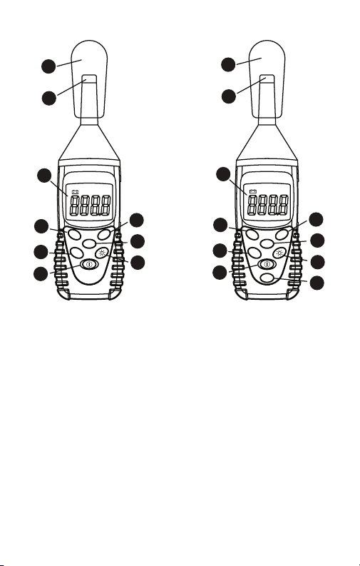
SM-10 SM-20
➊ Windscreen
Microphone
➋
LCD display
➌
Frequency weighting select button
➍
Maximum/Minimum Hold button
➎
Power button
➏
Backlight button
➐
Time weighting select button
➑
Data Hold button
➒
Record button
➓
3
Page 5

SM-10 / SM-20
Sound Level Meters
CONTENTS
Symbols .................................................................................................................5
Unpacking and Inspection ...................................................................................5
Introduction ..........................................................................................................5
Operation .............................................................................................................5
MAX/MIN ......................................................................................................... 6
HOLD ...............................................................................................................6
Backlight ..........................................................................................................6
Record (SM-20 Only) .......................................................................................6
Calibration Procedures ..................................................................................6
Specifications ........................................................................................................ 7
Maintenance and Repair ....................................................................................8
Battery Replacement .....................................................................................8
4
Page 6

SYMBOLS
Refer to the manual
Conforms to relevant
Australian standards.
Do not dispose of this
product as unsorted
municipal waste.
Complies with EU
directives
Warning and Precautions
For wind speeds over 10 m/sec (22.3 mph), use the windscreen on the •
microphone.
For general sound level measurements use A weighting. For checking the •
low-frequency content of noise use C weighting. If the C-Weighted level
is much higher than the A-weighted level, then there is a large amount of
low-frequency noise
For normal measurements use the FAST mode. For checking average level •
of fluctuation noise use the SLOW mode.
UNPACKING AND INSPECTION
Your shipping carton should include:
1 SM-10 / 20 sound level meter
1 9 volt battery
1 Download Suite CD-ROM (SM-20)
1 RS-232 to mini stereo phono jack (SM-20)
1 Users Manual
If any of the items are damaged or missing, return the complete package to
the place of purchase for an exchange.
INTRODUCTION
This Sound Level Meter has been designed to meet the measurement
requirements of safety Engineers, Health, Industrial safety offices and quality
control in various environments. This unit conforms to the IEC651 Type 2,
ANSI S1.4 Type 2, JISC1502 requirements for Sound Level Meters.
OPERATION
Press 1. button for power ON.
Select the desired response time and weighting. If the sound source 2.
consists of short bursts or only catching sound peak, set response to FAST.
To measure average sound level, use the slow setting. Select A weighting
for general noise sound level and C weighting for measuring sound level
of acoustic material.
5
Page 7

Hold the instrument comfortably in hand or fix on tripod and point the 3.
microphone at the suspected noise source, the sound pressure level will
be displayed.
MAX/MIN
The MAX MIN feature reads and updates the display to show the maximum
or minimum average value measured after you press the MAX MIN button.
Pressing the MAX MIN button for less than 1 second will put the meter into
a mode of displaying the maximum, minimum, average, or actual readings.
Each time the button is pressed, the meter will alternate between MAX
and MIN. Press the MAX MIN button for more than 2 seconds to disable this
feature.
HOLD
Freezes the reading present on the LCD at the moment the button is pressed.
To use this button feature set up the meter for the type of measurement and
range desired before pressing the button.
Backlight
Press the button you enable the display backlight to easy readings in dark
environments. Press more than 1 second to disable backlight, which however
it automatically OFF after 15 seconds.
Record (SM-20 Only)
Refer to CD-ROM for Download Suite
To transfer the data from the instrument to the PC the following procedure
must be followed:
TM
instructions .
Switch ON the instrument1.
Connect the serial output of the instrument to the serial output of the PC 2.
through the serial cable
Press the REC button on the SM-20.3.
Install the software and start it – Close the introduction window4.
Press F2 and follow the commands.5.
Refer to software help file for further instructions.6.
Calibration Procedures
Using a standard Acoustic Calibrator (SM-CAL1) (94dB, 1 kHz Sine wave)
Set meter for dBA and FAST. 1.
Insert the Microphone nozzle carefully into the insertion hole of the 2.
calibrator.
Press A/C button then press the HOLD button, hold the 2 buttons at 3.
the same time more than 1 second. LCD will be blinking to confirm
calibration.
6
Page 8

When LCD blinked, release the A/C and the HOLD buttons. The sound level 4.
meter will display 94.0 dBA . The calibration is done.
The 94 dB calibration process can be repeated until the meter reads 94.0 5.
dB. Recalibration cycle: 1 year.
SPECIFICATIONS
General
Display: 4 digits LCD
Microphone: 1/2 inch Electret condenser microphone.
Low Battery Indication: Replace battery when LCD displays “”.
Power Supply: 9V NEDA 1604, IEC 6F22, JIS 006P battery.
Power Life : Approx. 50 hrs (alkaline Battery).
Auto Power Off: Approx. 5 min
Environment: Indoor operation, < 2000 m
Temperature / Humidity
Operation: 5 °C to 40 °C (41°F to 104°F); < 80% RH
Storage: -10 °C to 60 °C (14°F to 140°F); < 70 %RH
Dimension: 200 x 55 x 38 mm (7.8 x 2.2 x 1.5 in)
Weight: 233g. (0.5 lb.) Including battery
-EMC: EN61326-1 This product complies with requirements of the
following European Community Directives: 89/336/EEC (Electromagnetic
Compatibility) and 73/23/EEC (Low Voltage) as amended by 93/68/EEC (CE
Marking). However, electrical noise or intense electromagnetic fields in the
vicinity of the equipment may disturb the measurement circuit. Measuring
instruments will also respond to unwanted signals that may be present within
the measurement circuit. Users should exercise care and take appropriate
precautions to avoid misleading results when making measurements in the
presence of electronic interference.
Electrical (Audio)
Standard applied: IEC 651 Type2, ANSI 1.4 Type 2.
Dynamic range: 50 dB.
Resolution: 0.1 dB, Display Update: 0.5 sec.
Time weighting: FAST(125mS), SLOW(1 sec).
Frequency range: 31.5 Hz to 8 kHz.
Measuring level range: (Auto Range)
A Weighting: 30 to 130 dB.
C Weighting: 35 to 130 dB.
Accuracy: ± 1.5 dB.
Calibration cycle: 1 year.
7
Page 9
MAINTENANCE AND REPAIR
OPEN
If there appears to be a malfunction during the operation of the meter, the
following steps should be performed in order to isolate the cause of the
problem.
Check the battery. Replace the battery immediately when the symbol 1.
“” appears on the LCD.
Review the operating instructions for possible mistakes in operating 2.
procedure.
Except for the replacement of the battery, repair of the meter should be
performed only by a Factory Authorized Service Center or by other qualified
instrument service personnel. The front panel and case can be cleaned with
a mild solution of detergent and water. Apply sparingly with a soft cloth and
allow to dry completely before using. Do not use aromatic hydrocarbons or
chlorinated solvents for cleaning.
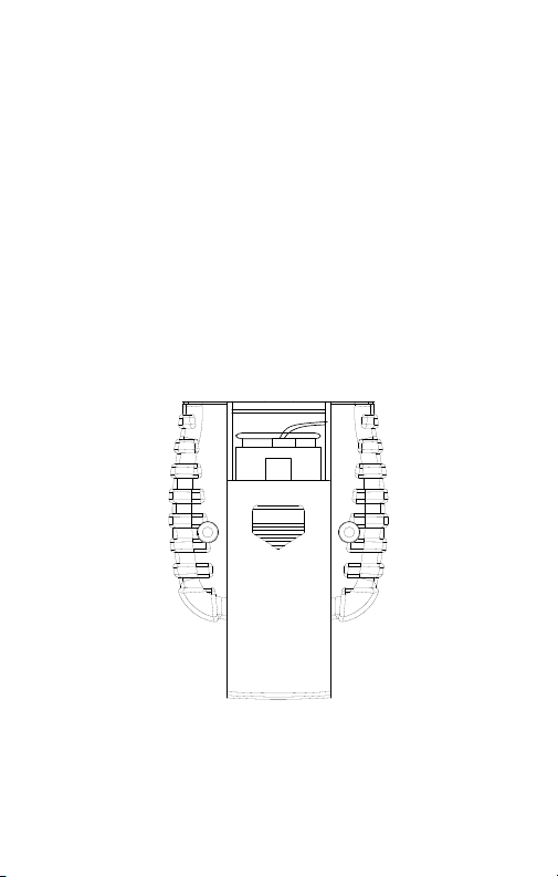
Battery Replacement
Turn off the meter and slide out the battery cover. Replace the battery 1.
with a NEDA type 1604 or equivalent 9V alkaline battery. Replace the
cover.
Remove battery when the SM-10/SM-20 is not used for extended period.2.
Battery Replacement
8
Page 10

SM-10 / SM-20
Sonomètres
Mode d’emploi
SM10_Rev001
© 2008 Amprobe Test Tools.
Tous droits réservés.
Français
9
Page 11

Limites de garantie et de responsabilité
Amprob e garantit l’absenc e de vices de matériaux et de fabrication de ce produit
pendant une pério de d’un (1) an prenant ef fet à la date d’achat . Cette garantie ne
s’applique pas aux fus ibles, aux piles j etables ni à tout produit mal utilisé, modifié,
contaminé, néglig é ou endommagé par accident o u soumis à des condi tions anormales
d’utilisation et de manipulation. Les dis tributeurs agr éés par Amprobe n e sont pas
autoris és à appliquer une garantie plu s étendue au nom d’Amp robe. Pour bénéficier
de la garantie, renvoyez le produit a ccompagné d’un justificatif d’achat aup rès d’un
centre de s ervices agréé par Amprobe Test Tools ou d’un distributeur ou d’u n revendeur
Amprob e. Voir la section Rép aration pour tous les détail s. LA PRESENTE GARAN TIE EST
LE SEUL ET E XCLUSIF RECOURS . TOUTES AUTRES GARANTI ES, EXPLICITES, IMP LICITES OU
STATUTAIRES, N OTAMMENT LE CAS ECHEANT L ES GARANTIE S DE QUALITE MARCH ANDE
OU D’ADAPTATION A U N OBJECTIF PARTICULIER , SONT EXCLUES PAR LE S PRESENTES. LE
FABRICANT NE SER A EN AUCUN CAS TEN U RESPONSABLE DES DOMMAG ES PARTICULIERS,
INDIRECTS, ACC IDENTELS OU CON SECUTIFS, NI D’AUCU NS DEGATS OU PERTES DE
DONNEES, SUR UNE BA SE CONTRACTUELLE, E XTRA-CO NTRACTUELLE OU AUTRE. Etant
donné que certaines juridi ctions n’admettent pas le s limitations d’une condition de
garantie implicite, o u l’exclusion ou la limi tation de dégâts accident els ou consécutifs,
il se peut que les limit ations et/ou les exclu sions de cette garantie ne s’appliquent pa s à
votre cas .
Réparation
Tous les outils de test renvoyés pour une réparation ou un étalonnag e couvert ou non par
la garantie doivent être accompagnés des élément s suivants : nom, raison sociale, adresse,
numéro de téléphone et justificatif d’achat. Ajou tez également une b rève descriptio n
du problè me ou du service demandé et i ncluez les cordon s de mesure avec l’appareil. Les
frais de remplacement ou de réparation hors garantie doivent être acquit tés par chèque,
mandat , carte de crédit av ec date d’expiratio n ou par bon de comman de payable à l’ordre
de Ampro be® Test Tools.
Remplacements et réparations sous garantie – Tous pays
Veuillez lire la déclaration de garantie et vérifier la pile avant de demander une réparation.
Pendant la période de garantie, tout outil de tes t défectueux peut être renvoyé auprès
de votre distributeur Ampro be® Test Tools pour être échan gé contre un produi t identique
ou similair e. Consultez la sec tion « Where to Buy » sur le site www.ampr obe.com pour
obtenir la liste des distributeurs dans vo tre région. Les appareils sous garantie devant être
remplac és ou réparés au Can ada et aux Etats-Unis peuvent également êt re envoyés dans
un centre d e services Amp robe® Test Tools (voi r les adresses ci -dessous ).
Remplacements et réparations hors garantie – Canada et Etats-Unis
Les appa reils à réparer hor s garantie au Canada et aux Etat s-Unis doiven t être envoyés
dans un cen tre de services Amprobe® Test Tools. Ap pelez Amprobe® Test Tools ou
renseignez-vou s auprès de votre lieu d ’achat p our connaître les tarifs en v igueur de
remplac ement ou de réparat ion.
Aux Etats-Unis Au Canada
Amprobe Test Tools Amprob e Test Tools
Evere tt, WA 98203 E-U Missis sauga, Ontario L4Z 1X9 Canada
Tél. : 877-A MPROBE (267-7623) Tél. : 905- 890-7600
Remplacements et réparations hors garantie – Europe
Les appa reils européens non couver ts par la garantie p euvent être remplacés par vo tre
distrib uteur Amprobe® Test Tools pour une somme n ominale. Consultez la section
« Where to Bu y » sur le site www.amprobe.com pour obtenir la lis te des distribu teurs dans
votre région.
Adresse postale europ éenne*
Amprobe
In den Engemat ten 14
79286 Glotter tal, Allemagn e
Tél. : +4 9 (0) 7684 80 09 - 0
*(Ré servée à la correspondan ce – Aucun remplace ment ou réparation n’est possible à
cette ad resse. Nos clien ts européens do ivent contacter leur dis tributeur.)
®
Test Tools Europ e
10
Page 12

REC
HOLD
+
MAX
FAST
SLOW
A / C
Fast Slow
HOLD MAX dBA
MIN dBCN
1
2
3
4
5
6
7
8
9
10
HOLD
+
MAX
FAST
SLOW
A / C
Fast Slow
HOLD MAX dBA
MIN dBCN
3
4
5
6
7
8
9
1
2
➊ Ecran anti-vent
Microphone
➋
Ecran LCD
➌
Bouton de sélection de pondération
➍
des fréquences
SM-20SM-10
➎ Bouton de maintien maximum/minimum
Bouton marche/arrêt
➏
Bouton de rétroéclairage
➐
Bouton de sélection de pondération temporelle
➑
Bouton de maintien d’affichage
➒
Bouton d’enregistrement
➓
11
Page 13

SM-10 / SM-20
Sonomètres
Symboles ............................................................................................................. 13
Deballage et inspection .....................................................................................13
Introduction ........................................................................................................13
Fonctionnement .................................................................................................13
MAX/MIN ....................................................................................................... 14
Maintien d’affichage ....................................................................................14
Rétroéclairage ............................................................................................... 14
Enregistrer (SM-20 seulement) .....................................................................14
Procédures d’étalonnage ............................................................................14
Specifications ...................................................................................................... 15
Entretien et reparation ..................................................................................... 16
Changement des piles .................................................................................16
12
Page 14

SYMBOLES
Se reporter au manuel.
Conforme aux normes
australiennes.
Ne pas mettre ce produit
au rebut avec les déchets
ménagers non triés.
Conforme aux directives
de l’UE.
Mises en garde et précautions
Installer l’écran anti-vent sur le micro quand la vitesse du vent est •
supérieure à 10 m/s (22,3 mph).
Utiliser une pondération A pour les mesures acoustiques globales. Pour •
vérifier le contenu en basse fréquence du bruit, utilisez une pondération
C. Le bruit à basse fréquence est important si le niveau pondéré C est très
supérieur au niveau pondéré A.
Utiliser le mode rapide FAST pour les mesures normales. Utilisez le mode •
lent SLOW pour vérifier le niveau moyen du bruit aléatoire.
DEBALLAGE ET INSPECTION
Le carton d’emballage doit inclure les éléments suivants :
1 sonomètre SM-10 / 20
1 pile de 9 volts
1 CD-ROM Download Suite (SM-20)
1 mini-prise phono/stéréo vers RS-232 (SM-20)
1 mode d’emploi
Si l’un de ces éléments est endommagé ou manquant, renvoyez le contenu
complet de l’emballage au lieu d’achat pour l’échanger.
INTRODUCTION
Ce sonomètre a été conçu conformément aux exigences de mesure des
ingénieurs travaillant dans la sécurité, la santé, les agences de sécurité
industrielle et le contrôle qualité dans divers environnements. Cet appareil
est conforme aux exigences CEI651 type 2, ANSI S1.4 type 2, JISC1502 pour
les sonomètres.
FONCTIONNEMENT
Appuyez sur le bouton 1. pour mettre l’appareil sous tension.
Sélectionnez la pondération et le temps de réponse souhaités. Si la source 2.
sonore comprend de brèves rafales ou ne capte que la crête du signal
acoustique, réglez la réponse sur FAST. Utilisez le réglage lent SLOW pour
mesurer le niveau sonore moyen. Sélectionnez la pondération A pour le
niveau de bruit global et la pondération C pour mesurer le niveau sonore
du matériel acoustique.
13
Page 15

3. Tenez l’instrument bien dans la main ou fixez-le sur un trépied, puis
pointez le micro vers la source de bruit suspectée ; le niveau de pression
acoustique s’affiche.
MAX/MIN
La fonction MAX MIN lit et met à jour l’affichage pour indiquer la valeur
maximum ou minimum quand le bouton MIN MAX est activé. Si le bouton
MAX MIN est enfoncé moins d’une seconde, l’appareil passe dans un mode
d’affichage présentant les valeurs maximum, minimum ou brutes. L’appareil
bascule alternativement entre MAX et MIN à chaque pression du bouton.
Appuyez sur le bouton MAX MIN pendant 2 secondes pour désactiver
cette fonction.
Maintien d’affichage
Ce bouton gèle la mesure affichée sur l’écran LCD. Pour utiliser cette
fonction, configurez l’appareil pour le type de mesure et la gamme souhaités
et appuyez sur le bouton.
Rétroéclairage
Appuyez sur ce bouton pour activer le rétroéclairage et lire facilement
les résultats dans les environnements faiblement éclairés. Appuyez
pendant plus d’une seconde pour désactiver le rétroéclairage, qui s’éteint
automatiquement après 15 secondes.
Enregistrer (SM-20 seulement)
Reportez-vous aux instructions du CD-ROM pour Download Suite
Pour transférer les données de l’instrument vers le PC, appliquez la
procédure suivante :
TM
.
Mettez l’instrument sous tension.1.
Branchez la sortie série de l’instrument à la sortie série du PC par le biais 2.
du câble série.
Appuyez sur le bouton REC sur le SM-20.3.
Installez le logiciel et démarrez-le. Refermez la fenêtre d’introduction.4.
Appuyez sur F2 et suivez les commandes.5.
Reportez-vous au fichier d’aide du logiciel pour toutes les instructions.6.
Procédures d’étalonnage
Utilisation d’un calibrateur acoustique standard (SM-CAL1) (signal sinusoïdal
1 kHz, 94 dB)
Réglez l’appareil sur dBA et FAST. 1.
Insérez soigneusement le nez du micro dans le trou d’insertion 2.
du calibrateur.
Appuyez sur le bouton A/C puis sur HOLD, maintenez les 2 boutons 3.
enfoncés en même temps pendant plus d’une seconde. L’écran LCD
clignote pour confirmer l’étalonnage.
14
Page 16

4. A l’apparition du clignotement, relâchez les boutons A/C et HOLD. Le
sonomètre affiche 94,0 dBA. L’étalonnage est terminé.
5. Le processus d’étalonnage à 94 dB peut être répété afin d’obtenir un
résultat de 94,0 dB sur le sonomètre. Cycle de réétalonnage : 1 an.
SPECIFICATIONS
Caractéristiques générales
Affichage : LCD à 4 chiffres
Microphone : Microphone à condensateur Electret
Témoin de décharge de la pile : Remplacez la pile à l’apparition de
Alimentation : Pile 9 V NEDA 1604, CEI 6F22, JIS 006P
Autonomie : Environ 50 h (pile alcaline)
Arrêt automatique : Environ 5 mn
Environnement : Fonctionnement en intérieur, < 2000 m
Température/Humidité :
Fonctionnement : 5 °C à 40 °C (41 °F à 104 °F) ; < 80 % HR
Entreposage : -10 °C à 60 °C (14 °F à 140 °F) ; < 70 %
Dimensions : 200 x 55 x 38 mm (7,8 x 2,2 x 1,5 po)
Poids : 233 g (0,5 lb) avec la pile
CEM : EN61326-1. Ce produit est conforme aux exigences des directives
suivantes de la Communauté européenne : 89/336/CEE (Compatibilité
électromagnétique) et 73/23/CEE (Basse tension) modifiée par 93/68/CEE
(Marquage CE). Toutefois, le bruit électrique ou les champs électromagnétiques
intenses à proximité de l’équipement sont susceptibles de perturber le
circuit de mesure. Les appareils de mesure réagissent également aux signaux
indésirables qui seraient présents dans le circuit de mesure. Les utilisateurs
doivent faire preuve de prudence et prendre les mesures nécessaires pour
éviter les erreurs de mesure en présence de parasites électromagnétiques.
Electricité (audio)
Norme appliquée : CEI 651 type 2, ANSI 1.4 type 2
Gamme dynamique : 50 dB
Résolution : 0,1 dB, actualisation de l’affichage : 0,5 s
Pondération temporelle : rapide (125 mS), lente (1 s)
Gamme de fréquence : 31,5 Hz à 8 kHz
Gamme de niveau de mesure : (Gamme automatique)
Pondération A : 30 à 130 dB
Pondération C : 35 à 130 dB
Précision : ± 1,5 dB
Cycle d’étalonnage : 1 an
1/2 po
« » sur l’écran LCD
15
Page 17

OPEN
ENTRETIEN ET REPARATION
Si une anomalie est suspectée pendant le fonctionnement du multimètre,
procédez comme suit pour isoler la cause du problème.
Vérifiez la pile. Remplacez immédiatement la pile à l’apparition du 1.
symbole « » sur l’écran LCD.
Consultez les consignes d’utilisation pour vérifier les erreurs possibles lors 2.
de l’utilisation.
Les interventions sur l’appareil, à l’exception du changement des piles,
doivent être effectuées en usine dans un centre de services agréé ou par un
autre personnel de réparation qualifié. La face avant et le boîtier peuvent
être nettoyés à l’aide d’une solution légère à base d’eau et de détergent.
Appliquez cette solution avec modération en utilisant un tissu doux et laissez
bien sécher avant l’utilisation. N’utilisez pas de solvants à base de chlore ou
d’hydrocarbures aromatiques pour le nettoyage.
Changement des piles
Mettez l’appareil hors tension et faites glisser le couvercle du 1.
compartiment de pile. Remplacez-la par une pile alcaline NEDA type 1604
ou équivalent de 9 V. Replacez le couvercle.
Retirez la pile si le SM-10 / SM-20 n’est pas utilisé pendant une 2.
période prolongée.
Changement des piles
16
Page 18

SM-10 / SM-20
Lautstärkemesser
Bedienungshandbuch
SM10_Rev001
© 2008 Amprobe Test Tools.
Alle Rechte vorbehalten.
Deutsch
17
Page 19

Beschränkte Gewährleistung und Haftungsbeschränkung
Es wird gewährleistet, dass dieses A mprobe-Pro dukt für die Dauer von einem Jah r ab
dem Kaufd atum frei von Materi al- und Fertigungsdefekten is t. Diese Gewährleistung
erstreckt sich n icht auf Sicherungen, Einwe gbatterien oder Schäde n durch Unfälle,
Nachläs sigkeit, Missbrauch, Än derungen oder abnormale Betriebsbeding ungen
bzw. unsa chgemäße Handhabung. Die Verkaufsstellen sind nicht dazu berechtigt,
diese Gewährleis tung im Namen von Am probe zu erweite rn. Um während der
Gewährleistung speriode Ser viceleistung en in Anspruch zu ne hmen, das Produkt mit
Kaufnachweis an ein autorisie rtes Amprobe Tes t Tools Service-Cente r oder an einen
Amprob e-Fachhändler/- Distributor einsenden. Nähere Einzelheite n siehe Abschnit t
„Reparatur“. DIESE GEWÄHRLEIS TUNG STELLT DEN EINZIGEN UND A LLEINIGEN
RECHTS ANSPRUCH AUF SCHADENERSATZ DAR. AL LE ANDEREN GEWÄH RLEISTUNGEN ,
VERTR AGLICH GEREGELTE ODER GESET ZLICHE VORGESCHRIEBENE, EINSCH LIESSLICH
DER GESETZLICH EN GEWÄHRLEIST UNG DER MARKT FÄHIGK EIT UND DER EIGNU NG
FÜR EINEN B ESTIMMTEN ZWECK, WERDEN ABGELEHNT. DER HER STELLER ÜBERNIMMT
KEINE HA FTUNG FÜR SPEZ IELLE, INDIREK TE, NEBEN- ODE R FOLGESCHÄDEN O DER
FÜR VERLUSTE, DIE AUF BELIEBIGER URSACHE ODER RECH TSTHEORIE BERUHEN. Weil
einige Staaten oder Länder d en Ausschluss o der die Einschränkung einer im plizierten
Gewährleistung s owie den Ausschluss von Beg leit- oder Folgeschäden nicht zulassen, ist
diese Gewährleis tungsbeschränkung möglicherweise für Sie nicht gültig.
Reparatur
Allen Geräten, die innerhalb o der außerhalb des Garantiezeitraums zur R eparatur
oder Kalibrierung eingese ndet werden, mü ssen mit folgenden Inform ationen und
Dokumenten vers ehen werden: Name des Kunden, Firmenname, Ad resse, Telefonnummer
und Kaufb eleg. Zusätzli ch bitte dem Messgerät ein e kurze Beschreib ung des Problems
oder der gewünsc hten Wartung sowi e die Messleitun gen beilegen. Di e Gebühren
für außer halb des Garantiezeitraums du rchgeführte Re paraturen oder für den
Ersatz von Instr umenten müssen per Sche ck, Zahlungsanweisung o der Kreditkar te
(Kred itkartennumm er mit Ablaufdatum) beglichen werden oder es muss ein Auf trag auf
Rechnun g an Amprobe® Test Tools form uliert werden.
Garantiereparaturen und -austausch - alle Länder
Bitte die Garantiee rklärung lesen u nd die Batterie prüfen, bevor Reparaturen angeforder t
werden. Während de r Garantieperiode können alle defekten Geräte zum Umtausch
gegen da sselbe oder ein ä hnliches Produk t an den Amprobe® Test Tools- Distributor
gesendet werde n. Ein Verzeichnis de r zuständigen Di stributoren is t im Abschnitt
„Where to Buy“ (Verkau fsstellen) au f der Website ww w.amprobe.com zu fi nden. Darüber
hinaus könn en in den USA und in Kanada Geräte an ein Ampro be® Test Tools Ser viceCenter ( siehe Adresse unten) zur Re paratur oder zum Um tausch einges endet werden.
Reparaturen und Ersatz außerhalb des Garantiezeitraums - USA und Kanada
Für Repara turen außerhalb des Garantiezeitraums i n den Vereinigten Staaten und
in Kanada werden die Geräte an ein A mprobe® Test Tools Ser vice-Center gesen det.
Auskunf t über die derzeit geltend en Reparatur- und Aus tauschgebühren erhal ten Sie von
Amprobe® Test Tools ode r der Verkaufsstelle.
In den U SA: In Kanada:
Amprobe Test Tools Amprob e Test Tools
Evere tt, WA 98203 Mississauga, ON L4Z 1X9
Tel.: 877-AMPRO BE (267-7623) Tel.: 905-89 0-7600
Reparaturen und Austausch außerhalb des Garantiezeitraums - Europa
Geräte mit abgelaufener Gara ntie können durch den zuständ igen Amprobe® Test ToolsDistrib utor gegen eine Gebühr ersetzt we rden. Ein Verzeichn is der zuständigen
Distrib utoren ist im Abs chnitt „Where to Buy“ (Verkau fsstellen) au f der Website
www.amprobe.com zu finde n.
Korresponden zanschrift für Eu ropa*
Amprobe® Test Tools Europ e
In den Engemat ten 14
79286 Glotter tal, Deutschland
Tel.: + 49 (0) 7684 8009 - 0
*(Nur Korrespo ndenz – keine Reparaturen und kein U mtausch unter di eser Anschrif t.
Kunden in Europa wenden sich an den zuständigen Dis tributor.)
18
Page 20

REC
HOLD
+
MAX
FAST
SLOW
A / C
Fast Slow
HOLD MAX dBA
MIN dBCN
1
2
3
4
5
6
7
8
9
10
HOLD
+
MAX
FAST
SLOW
A / C
Fast Slow
HOLD MAX dBA
MIN dBCN
3
4
5
6
7
8
9
1
2
SM-20SM-10
Windschirm
➊
Mikrofon
➋
LCD-Anzeige
➌
Auswahltaste für Frequenzbewertung
➍
Min/Max-Haltetaste
➎
Ein/Aus-Taste
➏
Hintergrundbeleuchtungstaste
➐
Auswahltaste für Zeitbewertung
➑
Daten-Haltetaste
➒
Aufzeichnungstaste
➓
19
Page 21

SM-10 / SM-20
Lautstärkemesser
Symbole ..............................................................................................................21
Auspacken und Überprüfen ..............................................................................21
Einführung ..........................................................................................................21
Bedienung ..........................................................................................................21
MAX/MIN ....................................................................................................... 22
HOLD .............................................................................................................22
Hintergrundbeleuchtung .............................................................................22
Aufzeichnen (nur SM-20) .............................................................................22
Kalibrierverfahren .......................................................................................22
Spezifikationen ..................................................................................................23
Wartung und Reparatur ...................................................................................24
Ersetzen der Batterie ................................................................................... 24
20
Page 22

SYMBOLE
Dieses Produkt nicht
Lesen Sie das Handbuch.
Übereinstimmung
mit den relevanten
australischen Normen.
im unsortierten
Kommunalabfall
entsorgen.
Übereinstimmung mit
EU-Vorschriften.
Warn- und Vorsichtshinweise
Für Windgeschwindigkeiten über 10 m/s den Windschirm auf dem •
Mikrofon verwenden.
Für allgemeine Lautstärke/Schallpegelmessung A-Bewertung verwenden. •
Zum Prüfen des Niederfrequenzgehalts von Rauschen C-Bewertung
verwenden. Wenn der C-bewertete Pegel viel höher ist als der
A-bewertete Pegel, dann liegt starkes Niederfrequenzrauschen vor.
Für normale Messungen den FAST-Modus verwenden. Zum Prüfen des •
mittleren Pegels von Verteilungsrauschen den SLOW-Modus verwenden.
AUSPACKEN UND ÜBERPRÜFEN
Der Verpackungskarton sollte Folgendes enthalten:
1 SM-10 / 20 Lautstärkemesser
1 9-Volt-Batterie
1 Download Suite CD-ROM (SM-20)
1 RS-232 auf Mini-Stereo-Tonabnehmerbuchse (SM-20)
1 Bedienungshandbuch
Wenn einer dieser Artikel beschädigt ist oder fehlt, die gesamte Lieferung
zwecks Ersatz an die Verkaufsstelle zurücksenden.
EINFÜHRUNG
Dieser Lautstärkemesser wurde konzipiert, um die Messanforderungen von
Sicherheitsfachleuten, Gesundheits- und Industriesicherheitsstellen und
Qualitätssicherung in verschiedenen Umgebungen zu erfüllen. Dieses Gerät
erfüllt die Anforderungen gemäß IEC651 Typ 2, ANSI S1.4 Typ 2 und JISC1502
für Lautstärke-/Schallpegelmesser.
BEDIENUNG
Zum EINSCHALTEN die Taste 1. drücken.
Die gewünschte Ansprechzeit und Bewertung auswählen. Wenn die 2.
Schallquelle aus kurzen Ausbrüchen besteht oder nur auffallenden
Spitzen, Ansprechzeit auf FAST einstellen. Zum Messen des mittleren
Schallpegels die SLOW-Einstellung verwenden. A-Bewertung für
allgemeine Rausch-Schallpegel auswählen und C-Bewertung zum Messen
des Schallpegels von akustischem Material.
21
Page 23

3. Das Messgerät bequem in der Hand halten oder auf einem Dreifuß
befestigen und das Mikrofon auf die vermutete Rauschquelle richten; der
Schalldruckpegel wird angezeigt.
MAX/MIN
Wenn die MIN MAX-Taste gedrückt wird, liest und aktualisiert die MIN
MAX-Funktion die Anzeige, um den Niedrigstwert, den Höchstwert bzw.
den mittleren Wert anzuzeigen. Wenn die MIN MAX-Taste weniger als eine
Sekunde lang gedrückt wird, wird das Messgerät in einen Modus geschaltet,
in dem die Höchst-, Niedrigst-, Mittel- oder tatsächlichen Werte angezeigt
werden. Bei jedem Drücken der Taste schaltet das Messgerät zwischen
MAX- und MIN-Messwerten um. Um diese Funktion zu beenden, die
MIN MAX-Taste länger als 2 Sekunden drücken.
HOLD
Der Datenhaltemodus friert den derzeit auf der LCD vorhandenen Messwert
zum Zeitpunkt des Tastendrucks ein. Um diese Tastenfunktion zu verwenden,
das Messgerät vor dem Drücken der Taste für den gewünschten Typ von
Messung und den gewünschten Bereich einrichten.
Hintergrundbeleuchtung
Drücken der Taste aktiviert die Hintergrundbeleuchtung der Anzeige, was
das Ablesen von Messwerten in dunklen Umgebungen vereinfacht. Die Taste
mehr als eine Sekunde gedrückt halten, um die Hintergrundbeleuchtung zu
deaktivieren, die sich jedoch nach 15 Sekunden automatisch ausschaltet.
Aufzeichnen (nur SM-20)
Für Anleitungen zur Download Suite
Um die Daten vom Messgerät auf den PC zu übertragen, das folgende
Verfahren verwenden:
TM
siehe die CD-ROM.
Das Messgerät einschalten.1.
Den seriellen Ausgang des Messgeräts über das serielle Kabel mit dem 2.
seriellen Anschluss des PCs verbinden.
Auf dem SM-20 die Taste REC drücken.3.
Die Software installieren und starten; das Startfenster schließen.4.
F2 drücken und die Anweisungen befolgen.5.
Für weitere Anweisungen siehe die Hilfefunktion in der Software.6.
Kalibrierverfahren
Mit einem Standard-Akustik-Kalibrator (SM-CAL1) (94 dB, 1 kHz Sinuswelle).
Das Messgerät für dBA und FAST einstellen. 1.
Das Mikrofon vorsichtig in die Öffnung am Kalibrator einführen. 2.
Die Taste A/C drücken, dann die Taste HOLD drücken und dann diese 3.
beiden Tasten gleichzeitig mehr als 1 Sekunde gedrückt halten. Die LCD
blinkt, um die Kalibrierung zu bestätigen.
22
Page 24

4. Sobald die LCD blinkt, die Tasten A/C und HOLD loslassen. Der
Schallpegelmesser zeigt 94,0 dBA an. Die Kalibrierung ist abgeschlossen.
5. Der 94-dB-Kalibrierprozess kann wiederholt werden, bis das Messgerät
94,0 dB anzeigt. Kalibrierzyklus: 1 Jahr.
SPEZIFIKATIONEN
Allgemein
Anzeige: 4 Stellen LCD
Mikrofon: 1/2-Zoll-Elektret-Kondensatormikrofon
Anzeige für schwache Batterie: Die Batterie ersetzen, wenn auf der
Stromversorgung: Batterie 9-V-NEDA 1604, IEC 6F22,
Batterielebensdauer: Ungefähr 50 Stunden (Alkalibatterie)
Automatische Ausschaltung: Ungefähr 5 Min
Umgebung: Gebrauch in Gebäuden, Betrieb
Temperatur / Feuchtigkeit
Betrieb: 5 °C bis 40 °C; < 80 % RH
Lagerung: -10 °C bis 60 °C; < 70 % RH
Abmessungen: 200 x 55 x 38 mm
Gewicht: 233 g, einschließlich Batterie
-EMV: EN61326-1. Dieses Produkt erfüllt die Anforderungen der folgenden
EU-Richtlinien: 89/336/EEC (Elektromagnetische Verträglichkeit) und 73/23/EEC
(Niederspannung) mit dem Zusatz 93/68/EEC (CE-Kennzeichnung). Elektrisches
Rauschen oder intensive elektromagnetische Felder in der Nähe des Geräts
können jedoch den Messschaltkreis stören. Messgeräte reagieren auch auf
unerwünschte Impulse/Signale, die unter Umständen im Messschaltkreis
vorkommen. Die Benutzer müssen die nötige Sorgfalt walten lassen und
geeignete Vorkehrungen treffen, um irreführende Ergebnisse bei Messungen
zu vermeiden, wenn elektronische Störeinflüsse vorhanden sind.
Elektrisch (Audio)
Normen: IEC 651 Typ 2, ANSI 1.4 Typ 2
Dynamischer Bereich: 50 dB
Auflösung: 0,1 dB, Anzeigeaktualisierung: 0,5 s
Zeitbewertung: FAST (125 ms), SLOW (1 s)
Frequenzbereich: 31,5 Hz bis 8 kHz
Messpegelbereich: (Autom. Bereich)
A-Bewertung: 30 bis 130 dB
C-Bewertung: 35 bis 130 dB
Genauigkeit: ± 1,5 dB
Kalibrierzyklus: 1 Jahr
LCD-Anzeige erscheint
JIS 006P
unterhalb 2000 m
23
Page 25

OPEN
WARTUNG UND REPARATUR
Wenn ein Fehlverhalten während des Betriebs des Messgeräts vermutet wird,
sollten die folgenden Schritte durchgeführt werden, um die Ursache des
Problems genau zu bestimmen.
Die Batterien prüfen. Die Batterie sofort ersetzen, wenn das Symbol 1.
auf der LCD-Anzeige erscheint.
Die Bedienungsanleitungen studieren, um mögliche Fehler bei der 2.
Bedienung zu erkennen.
Außer dem Ersetzen der Batterie sollten Reparaturen am Messgerät
ausschließlich durch werkseitig autorisiertes Servicepersonal oder anderes
Fachpersonal durchgeführt werden. Die Vorderseite und das Gehäuse
können mit einer milden Lösung von Reinigungsmittel und Wasser gereinigt
werden. Die Lösung spärlich mit einem weichen Tuch anwenden und
das Gerät vor Gebrauch vollständig trocknen lassen. Keine aromatischen
Kohlenwasserstoffe oder Chlorlösungsmittel zur Reinigung verwenden.
Ersetzen der Batterie
Das Messgerät ausschalten und die Batterieabdeckung aufschieben. 1.
Die Batterie durch eine NEDA Typ 1604 oder eine gleichwertige
9-V-Alkalibatterie ersetzen. Die Abdeckung wieder anbringen.
Die Batterie entfernen, wenn der SM-10/SM-20 längere Zeit nicht 2.
verwendet wird.
Ersetzen der Batterie
24
Page 26

SM-10 / SM-20
Fonometri
Manuale d’Uso
SM10_Rev001
© 2008 Amprobe Test Tools.
Tutti i diritti riservati.
Italiano
25
Page 27

Garanzia limitata e limitazione di responsabilità
Questo prodot to Amprobe sarà es ente da difetti di materiale e fabbricazione per un
anno a deco rrere dalla data di acquisto. S ono esclusi da que sta garanzia i fusi bili, le
pile monouso e i danni c ausati da incidenti, neglig enza, uso improprio, alterazione,
contaminazione o con dizioni anomale di fu nzionamento o manip olazione. I rivenditori
non sono autorizzati a offrire n essun’altra garanzia a nome della A mprobe. Per richiedere
un inter vento durante il periodo di garanzia, restituire il pro dotto, allegando la ricevu ta
di acquis to, a un centro di assi stenza autorizzato Amprobe Test Tools opp ure a un
rivenditore o distributore A mprobe locale. P er ulteriori informazioni ved ere la sezione
Riparazio ni. QUESTA GARANZIA È IL SOLO RICORSO A DISPOSIZIONE DELL’ACQUIRENTE
E SOSTITUISCE QUALSIA SI ALTRA GARANZIA, ES PRESSA, IMPLICITA O PREV ISTA DALLA
LEGGE, COMPRESA , MA NON A TITOLO ESCLUSIVO, QUALSIASI GARANZIA IMPL ICITA DI
COMMERC IABILITÀ O DI IDONEITÀ PER SCOPI PAR TICOLARI. IL PRODUT TORE NON SARÀ
RESPON SABILE DI DANNI O PERDITE SPECIALI , INDIRETT I O ACCIDENTALI, DERI VANTI DA
QUALSI ASI CAUSA O TEORI A. Poiché alcuni s tati o Paesi non permettono l’esclusione o la
limitazione di una garanzia implicita o di danni a ccidentali o indiretti, questa limi tazione
di respo nsabilità potre bbe non riguardare l’acquiren te.
Riparazioni
A tutti gli s trumenti di misura restituiti per inte rventi in garanzia o non coper ti dalla
garanzia, oppure pe r la taratura, devon o essere allegate le seguenti informazioni: il
proprio n ome e quello dell’azienda, indirizzo, numero telefonico e ricevuta di acquis to.
Allegare anche una breve descrizione del p roblema o dell’intervento richies to e i cavi di
misura. Gli importi dovuti pe r sostituzioni o rip arazioni non coper te dalla garanzia vann o
versat i tramite assegno , vaglia bancario, carta di credito con da ta di scadenza, o ppure
ordine di acquisto all’ordine di Amprobe® Test Tools.
Sostituzioni e riparazioni in garanzia – Tutti i Paesi
Si prega di l eggere la garanzia e di controllar e la pila prima di richie dere una riparazion e.
Durante il p eriodo di garanzia, si può restituire uno s trumento difet toso al rivenditore
Amprobe® Test Tools per ricevere un prodotto identico o analogo. La sezione “W here to
Buy” del sito www. amprobe.com con tiene un elenco dei distribu tori più vicini. Negli Stati
Uniti e nel C anada gli strumenti da sostituire o riparare in garanzia posson o essere inviati
anche a un ce ntro di assistenza Amprob e® Test Tools, agli indirizzi s eguenti.
Sostituzioni e riparazioni non coperte dalla garanzia – U.S.A. e Canada
Per ripara zioni non coperte dalla garanzia, negli Stati Uniti e nel C anada, lo strum ento
deve ess ere inviato a un centro d i assistenza Amprobe® Test Tools. Rivolgers i alla
Amprobe® Test Tools o al rive nditore per infor mazioni sui costi delle riparazioni e
sostituzioni.
U.S.A. Canada
Amprobe Test Tools Amprob e Test Tools
Evere tt, WA 98203, U.S .A. Mississauga, ON L4 Z 1X9 Can ada
Tel.: 877-AMPRO BE (877 267 7623) Tel.: +1 905 8 90 7600
Sostituzioni e riparazioni non coperte dalla garanzia – Europa
Gli strum enti acquistati in Europa e non coperti d alla garanzia possono essere sostit uiti
dal rivenditore Amp robe® Test Tools per un importo nominale. La sezione “ Where to Buy”
del sito w ww.amprobe.com contien e un elenco dei dist ributori più vicini.
Reca pito postale eur opeo*
Amprobe® Test Tools Europ e
In den Engemat ten 14
79286 Glotter tal, Germania
Tel.: + 49 (0) 7684 8009 – 0
* (Solo p er corrisponde nza – Non rivolger si a questo indiriz zo per riparazioni o
sostituzioni. Si pregano i clienti europe i di rivolgersi al pr oprio rivenditor e.)
26
Page 28

REC
HOLD
+
MAX
FAST
SLOW
A / C
Fast Slow
HOLD MAX dBA
MIN dBCN
1
2
3
4
5
6
7
8
9
10
HOLD
+
MAX
FAST
SLOW
A / C
Fast Slow
HOLD MAX dBA
MIN dBCN
3
4
5
6
7
8
9
1
2
SM-20SM-10
Schermo antivento
➊
Microfono
➋
Display a cristalli liquidi
➌
Pulsante di selezione pesatura di frequenza
➍
Pulsante di mantenimento valori minimo
➎
e massimo
➏ Pulsante di alimentazione
Pulsante di retroilluminazione
➐
Pulsante di selezione pesatura nel tempo
➑
Pulsante di mantenimento dei dati
➒
Pulsante di registrazione
➓
27
Page 29

SM-10 / SM-20
Fonometri
Simboli ................................................................................................................29
Disimballaggio e ispezione ................................................................................ 29
Introduzione ....................................................................................................... 29
Funzionamento ..................................................................................................29
Funzione MAX/MIN ......................................................................................30
Hold (Mantenimento dei dati) ..................................................................... 30
Retroilluminazione .......................................................................................30
Registrazione (solo SM-20) ........................................................................... 30
Procedure di taratura ...................................................................................30
Specifiche ............................................................................................................ 31
Manutenzione e riparazioni .............................................................................. 32
Sostituzione della pila ..................................................................................32
28
Page 30

SIMBOLI
Non smaltire questo
Consultare il manuale.
Conforme alle norme
australiane di pertinenza.
prodotto assieme
ad altri rifiuti solidi
non differenziati.
Conforme alle
direttive UE.
Avvertenze e precauzioni
In presenza di venti superiori a 10 m/s, applicare lo schermo antivento •
al microfono.
Per le misure generali del livello del suono usare la pesatura A. Per il •
controllo del contenuto a bassa frequenza del rumore, usare la pesatura C.
Se il livello rilevato con la pesatura C è considerevolmente superiore a
quello della pesatura A, significa che vi è un’elevata quantità di rumore a
bassa frequenza.
Per le misure normali, usare la modalità FAST (Veloce). Per controllare il •
livello medio di un rumore fluttuante, usare la modalità SLOW (Lenta).
DISIMBALLAGGIO E ISPEZIONE
La confezione deve contenere:
1 fonometro SM-10/SM-20
1 pila da 9 V
1 CD-ROM con il software Download Suite (SM-20)
1 cavo con connettore RS-232 e jack fono mini stereo (SM-20)
1 manuale d’uso
Se uno di questi articoli è danneggiato o manca, restituire l’intera confezione
al punto di acquisto perché venga sostituita.
INTRODUZIONE
Questo fonometro è stato progettato per soddisfare i requisiti delle misure
che devono essere eseguite da tecnici della sicurezza, strutture sanitarie,
uffici di sicurezza industriale e controllo della qualità in svariati ambienti. Lo
strumento è conforme alle norme IEC651 tipo 2, ANSI S1.4 tipo 2 e JISC1502
relative ai fonometri.
FUNZIONAMENTO
Premere il pulsante 1. per accendere lo strumento.
Selezionare il tempo di risposta e la pesatura. Se la fonte del suono 2.
emette scariche brevi o se si intende catturare solo il picco del suono,
impostare la modalità di risposta su FAST. Per misurare il livello medio
del suono, usare la modalità SLOW. Selezionare la pesatura A per livelli
di rumore generali e la pesatura C per misurare il livello del suono di
materiali acustici.
29
Page 31

3. Tenere lo strumento in mano comodamente o metterlo su un treppiede e
quindi puntare il microfono verso la fonte del suono; si visualizza il livello
di pressione sonora.
Funzione MAX/MIN
Una volta premuto il pulsante corrispondente, la funzione MIN MAX
aggiorna il display in modo da visualizzare il valore medio, massimo o minimo
misurato. Premendo il pulsante per meno di un secondo si attiva la funzione
di visualizzazione della lettura massima, minima, media o effettiva. Ogni
volta che si preme questo pulsante, il misuratore alterna fra la funzione MAX
e la funzione MIN. Per disabilitare questa funzione mantenere premuto il
pulsante MAX MIN per più di due secondi.
Hold (Mantenimento dei dati)
Ferma la lettura presente sul display quando si preme il pulsante. Per usare
questa funzione, prima di premere il pulsante configurare lo strumento in
base al tipo di misura e alla portata desiderata.
Retroilluminazione
Premere il pulsante per attivare la retroilluminazione, che facilita la lettura
del display in ambienti poco illuminati. Tenerlo premuto per oltre 1 secondo
per disabilitare la retroilluminazione; la funzione si disattiva comunque
automaticamente dopo 15 secondi.
Registrazione (solo SM-20)
Per istruzioni sull’uso del software Download Suite™, consultare il CD-ROM.
Per trasferire i dati dallo strumento al PC, procedere come segue.
Accendere lo strumento.1.
Con il cavo seriale, collegare l’uscita seriale dello strumento all’uscita 2.
seriale del PC.
Premere il pulsante REC dell’SM-20.3.
Installare il software e avviarlo. Chiudere la finestra di introduzione.4.
Premere F2 e seguire le istruzioni.5.
Fare riferimento alla Guida in linea del software per ulteriori istruzioni.6.
Procedure di taratura
Usando un calibratore acustico standard (SM-CAL1) da 94 dB, con onda
sinusoidale da 1 kHz, procedere come segue.
Impostare il fonometro in modalità dBA e FAST. 1.
Inserire la punta del microfono con cautela nell’apposito foro 2.
del calibratore.
Premere il pulsante A/C e quindi il pulsante HOLD; tenerli premuti 3.
contemporaneamente per oltre 1 secondo. Il display lampeggia per
confermare la taratura.
30
Page 32

4. Quando il display lampeggia, rilasciare i pulsante A/C e HOLD. Il
fonometro visualizza 94.0 dBA. La taratura è così completata.
5. La procedura può essere ripetuta finché lo strumento non indica 94.0 dB.
L’intervallo di ritaratura è di 1 anno.
SPECIFICHE
Generali
Display: A cristalli liquidi a 4 cifre
Microfono: A electret da 1/2 pollice
Indicatore di bassa carica della pila: Sostituire la pila quando il display
Alimentazione: Una pila da 9 V, NEDA 1604, IEC 6F22,
Autonomia della pila: Circa 50 ore (pila alcalina)
Spegnimento automatico: Dopo circa 5 minuti
Ambiente: Funzionamento in locali chiusi, fino
Temperatura e umidità:
Esercizio: Da 5 °C a 40 °C; < 80% di umidità relativa
Immagazzinaggio: Da -10 °C a 60 °C; < 70% di umidità
Dimensioni: 200 x 55 x 38 mm
Peso: 233 g pila inclusa
Compatibilità elettromagnetica: EN61326-1. Questo prodotto risponde
ai requisiti delle seguenti direttive della Comunità Europea: 89/336/CEE
(compatibilità elettromagnetica) e 73/23/CEE (basse tensioni) modificate
dalla direttiva 93/68/CEE (marchio CE). Tuttavia, rumore elettrico o campi
elettromagnetici intensi vicino all’apparecchio possono disturbare il circuito
di misura. Gli strumenti di misura rispondono anche a segnali indesiderati,
eventualmente presenti nel circuito di misura. Gli utenti devono esercitare
cautela e prendere le opportune precauzioni per evitare risultati falsi quando
si eseguono misure in presenza di interferenze elettroniche.
Specifiche elettriche (audio)
Standard applicati: IEC 651 tipo 2, ANSI 1.4 tipo 2
Portata dinamica: 50 dB
Risoluzione: 0,1 dB; aggiornamento del display: 0,5 s
Pesatura temporizzata: FAST (125 ms), SLOW (1 s)
Intervallo di frequenza: Da 31,5 Hz a 8 kHz
Portata: (Selezione automatica)
Pesatura A: Da 30 dB a 130 dB
Pesatura C: Da 35 dB a 130 dB
Precisione: ± 1,5 dB
Intervallo di ritaratura: 1 anno
visualizza “”
JIS 006P
a 2000 m
relativa
31
Page 33

OPEN
MANUTENZIONE E RIPARAZIONI
Se lo strumento non sembra funzionare bene, procedere come segue per
individuare la causa del problema.
Controllare la pila. Sostituirla immediatamente, non appena compare il 1.
simbolo “” sul display a cristalli liquidi.
Rileggere le istruzioni per l’uso, per accertarsi di non avere compiuto 2.
operazioni sbagliate.
Fatta eccezione per la sostituzione della pila, qualsiasi intervento di
manutenzione o riparazione dello strumento deve essere eseguito
esclusivamente presso un centro di assistenza autorizzato dalla fabbrica
o da altro personale di manutenzione qualificato. Il pannello anteriore e
l’involucro possono essere puliti con una soluzione di detergente neutro e
acqua. Applicare la soluzione in quantità moderata con un panno morbido
e lasciare asciugare completamente prima dell’uso. Non usare idrocarburi
aromatici o solventi clorurati per la pulizia.
Sostituzione della pila
Spegnere lo strumento e togliere il coperchio della pila facendolo 1.
scorrere. Sostituire la pila scarica con una NEDA tipo 1604 o con una pila
alcalina da 9 V equivalente. Reinstallare il coperchio.
Togliere la pila se non si usa il fonometro SM-10/SM-20 per lunghi periodi.2.
Sostituzione della pila
32
Page 34

SM-10 / SM-20
Sonómetros
Manual de uso
SM10_Rev001
© 2008 Amprobe Test Tools.
Reservados todos los derechos.
Español
33
Page 35

Garantía limitada y limitación de responsabilidad
Su producto Amprobe estará libre de defectos de material y mano de obra durante 1 año
a partir d e la fecha de adquisición. Esta garantía n o cubre fusibles , baterías desc artables
o daños que sean consecuencia de accidentes, negligencia , uso indebido, alteración ,
contaminación o con diciones anormales de uso o manipulaci ón. Los revended ores no
están autorizados a exten der ninguna otra garantía en nombre de Amprobe. Para ob tener
servi cio durante el perío do de garantía, devuelva el pro ducto con un compr obante de
compra a un centro de servicio au torizado por Amprobe de equ ipos de comprobación o a
un conces ionario o distribuidor de Am probe. Consulte l a sección Reparación para obtener
información más detallada. ESTA GARANTÍA CONSTITUYE SU ÚNICO RE SARCIMIENTO. L AS
DEMÁS GARANTÍAS, TAN TO EXPRESAS O IM PLÍCITAS COMO ESTATUTARIAS, IN CLUYENDO
LAS GARANT ÍAS IMPLÍCITAS DE ADECUACI ÓN PARA UN PROPÓS ITO DETERMINA DO O
COMERCI ABILIDAD, QUEDAN POR LA PRESENTE DESCONOCIDAS. EL FAB RICANTE NO
SERÁ RESPONSA BLE DE NINGÚN DAÑO O P ÉRDIDA, TANTO ESPECIAL COMO I NDIRECTO,
CONTIN GENTE O RESULTANTE QUE SURJA DE CUALQUIER CAUSA O TEORÍA. Debid o a que
cierto s estados o países no permi ten la exclusión o limi tación de una garan tía implícita o
de los daños contingentes o res ultantes, esta limitac ión de responsabilidad puede no regir
para usted.
Reparación
Todas las her ramientas de pru eba devueltas para calibra ción o reparación cubierta o n o
por la garantía deben estar acompañadas por lo siguiente: s u nombre, el nombr e de la
compañía , la dirección, el número de telé fono y una prueba de compra. Además, incluya
una breve descripc ión del problema o del servi cio solicitado y lo s conductores de prueba
del medidor. La repara ción fuera de garantía o los cargos de reemplazo debe n remitirse
en la forma d e un cheque, un giro postal, una tarjet a de crédito con fecha de vencimiento
o una orden de compra pa gadera a Amprobe® Test Tools.
Reparaciones y reemplazos cubiertos por la garantía (todos los países)
Sírvas e leer la declaración de garantía y comprue be su batería antes d e solicitar la
reparación. Durante el período de garantía, cualqui er herramienta de comproba ción
defec tuosa puede ser d evuelta a su distribuidor d e Amprobe® Test Tools para un
interca mbio por el mismo producto u otro similar. Con sulte la sección “W here to Buy”
del sitio w ww.amprobe.com en Inte rnet para obtener una lista d e los distribuidores
cercano s a usted. Asimi smo, las unidades de reparación en garan tía y las unidades de
reemplazo en los Est ados Unidos y Canadá tambi én pueden enviar se al Centro de ser vicio
Amprobe® Test Tools (co nsulte la dirección más abajo).
Reparaciones y reemplazos no cubiertos por la garantía (Estados Unidos
y Canadá)
Las reparaciones fuera de la garantía en lo s Estados Unido s y Canadá deben env iarse a un
Centro de s ervicio de Amprobe
punto de compra para conocer las t arifas actuales de reparación y reemplazo.
En Est ados Unidos En Canadá
Amprobe Test Tools Amprob e Test Tools
Evere tt, WA 98203 Mississauga, Ontario L 4Z 1X9
Tel.: 877-AMPRO BE (267-7623) Tel.: 905-89 0-7600
Reparaciones y reemplazos no cubiertos por la garantía (Europa)
El distrib uidor de Amprobe® Test Tools puede reempl azar las unidades v endidas en Europa
no cubier tas por la garantía por un costo nominal. C onsulte la sección “Where to Buy” del
sitio ww w.amprobe.com en Intern et para obtener una lista de lo s distribuidore s cercanos
a usted.
Dire cción para envío de correspon dencia en Europa*
Amprobe® Test Tools Europ e
In den Engemat ten 14
79286 Glotter tal, Alemania
Tel.: + 49 (0) 7684 8009 - 0
*(Sólo correspondencia. En est a dirección no se realizan reparaciones ni re emplazos. Los
clientes europeo s deben poners e en contacto con su distribuidor).
®
Test Tools. Llame a Ampro be® Test Tools o solicite en su
34
Page 36

REC
HOLD
+
MAX
FAST
SLOW
A / C
Fast Slow
HOLD MAX dBA
MIN dBCN
1
2
3
4
5
6
7
8
9
10
HOLD
+
MAX
FAST
SLOW
A / C
Fast Slow
HOLD MAX dBA
MIN dBCN
3
4
5
6
7
8
9
1
2
SM-20SM-10
Protector de viento
➊
Micrófono
➋
Pantalla LCD
➌
Botón de selección de ponderación de frecuencias
➍
Botón de retención máximo/mínimo
➎
Botón de encendido/apagado
➏
Botón de retroiluminación
➐
Botón de selección de ponderación de tiempo
➑
Botón de retención de datos
➒
Botón de grabación
➓
35
Page 37

SM-10 / SM-20
Sonómetros
Símbolos ..............................................................................................................37
Desembalaje e inspección .................................................................................. 37
Introducción .......................................................................................................37
Operación ...........................................................................................................37
MAX MIN ....................................................................................................... 38
HOLD (Retención de datos) .......................................................................... 38
Retroiluminación ..........................................................................................38
Grabación (sólo SM-20) ................................................................................38
Procedimientos de calibración .....................................................................38
Especificaciones .................................................................................................. 39
Mantenimiento y reparación .............................................................................40
Reemplazo de baterías .................................................................................40
36
Page 38

SÍMBOLOS
No se deshaga de este pro-
Consulte el manual.
Cumple con las
principales normas
australianas.
ducto utilizando los servicios
municipales de recolección
de desechos sin clasificar.
Cumple las directivas de
la UE.
Advertencias y precauciones
En presencia de vientos superiores a 10 m/seg (22,3 mph), utilice el •
protector de viento del micrófono.
Para mediciones generales de sonidos, utilice la ponderación A. •
Para comprobar el contenido de frecuencias bajas de ruido, utilice
la ponderación C. Si el nivel ponderado C es muy superior al nivel
ponderado A, significa que hay mucho ruido de baja frecuencia.
En mediciones normales, utilice el modo rápido (FAST). Para comprobar el •
nivel medio de un ruido que fluctúa, utilice el modo lento (SLOW).
DESEMBALAJE E INSPECCIÓN
La caja de envío debe incluir:
1 sonómetro SM-10/SM-20
1 batería de 9 voltios
1 CD-Rom de Download Suite (SM-20)
1 toma de RS-232 a micrófono miniestéreo (SM-20)
1 manual de uso
Si alguno de los elementos estuviera dañado o faltara, devuelva el paquete
completo al lugar de compra para hacer un cambio.
INTRODUCCIÓN
Este sonómetro está diseñado para satisfacer los requisitos de ingenieros
de seguridad, técnicos de salud y riesgos laborales y controles de calidad en
diferentes entornos. Esta unidad cumple los requisitos IEC651 tipo 2, ANSI
S1.4 tipo 2 y JISC1502 para sonómetros.
OPERACIÓN
Pulse el botón 1. para encender el equipo.
Seleccione el tiempo de respuesta y la ponderación que desee. Si la 2.
fuente de sonido se compone de ráfagas o si solamente desea capturar
el pico de sonido, establezca el tiempo de respuesta en FAST. Para medir
la intensidad media, utilice el ajuste SLOW. Seleccione la ponderación A
para ruidos generales y la ponderación C para medir el sonido de
material acústico.
37
Page 39

3. Sostenga el aparato cómodamente en la mano, o fíjelo en un trípode y
apunte el micrófono a la fuente de ruido sospechada; la pantalla indicará
la presión acústica.
MAX MIN
La función MAX MIN toma lecturas y actualiza la pantalla para presentar el
valor máximo o mínimo medio medido después de pulsar el botón MIN MAX.
La pulsación del botón MAX MIN durante menos de 1 segundo lleva al
medidor al modo de presentación en la pantalla de las lecturas máxima,
mínima, media o real. Cada vez que se pulse el botón, el medidor alternará
entre MAX y MIN. Para desactivar esta función, mantenga pulsado el botón
MAX MIN durante más de 2 segundos.
HOLD (Retención de datos)
Congela la lectura de LCD presente en el momento de pulsar el botón. Para
usar la función de este botón, configure el tipo y el rango de medición que
desee antes de pulsarlo.
Retroiluminación
Pulse el botón para encender la retroiluminación y facilitar la lectura en
entornos de oscuridad. Pulse durante más de 1 segundo para desactivar
la retroiluminación, que se desactivará automáticamente transcurridos
15 segundos.
Grabación (sólo SM-20)
Consulte las instrucciones del CD-ROM de Download Suite
TM
.
Para transferir datos del instrumento al PC, siga este procedimiento:
Encienda el instrumento.1.
Conecte la salida serie del instrumento a la salida serie del PC por medio 2.
del cable serie.
Pulse el botón REC del SM-20.3.
Instale el software y ábralo. Cierre la ventana de presentación.4.
Pulse F2 y siga los comandos.5.
Encontrará más instrucciones en el archivo de ayuda del software.6.
Procedimientos de calibración
Con un calibrador acústico estándar (SM-CAL1) (94 dB, onda sinoidal de 1 kHz)
Configure los ajustes del sonómetro en dBA y FAST. 1.
Con cuidado, inserte la boquilla del micrófono en el orificio del calibrador. 2.
Pulse el botón A/C y luego el botón HOLD; manténgalos pulsados al mismo 3.
tiempo durante más de 1 segundo. La pantalla LCD parpadeará para
confirmar la calibración.
Cuando la pantalla LCD parpadee, suelte los botones A/C y HOLD. 4.
El sonómetro mostrará una lectura de 94,0 dBA. La calibración ya
está realizada.
38
Page 40

5. El proceso de calibración de 94 dB puede repetirse hasta que el sonómetro
indique una lectura de 94,0 dB. Ciclo de recalibración: 1 año.
ESPECIFICACIONES
Generales
Pantalla: LCD de 4 dígitos
Micrófono: Micrófono con condensador Electret de
Señal de batería descargada: Cambie la batería cuando aparezca “”
Alimentación: Batería de 9 V NEDA 1604, IEC 6F22,
Duración de la batería: Unas 50 horas (alcalina)
Apagado automático: Aprox. 5 minutos
Ambiente: Funcionamiento en interiores, < 2.000 m
Temperatura/Humedad
Operación: 5 °C a 40 °C (41 °F a 104 °F); < 80 % HR
Almacenamiento: -10 °C a 60 °C (14 °F a 140 °F); < 70 % HR
Dimensión: 200 x 55 x 38 mm (7,8 x 2,2 x 1,3 pulg)
Peso: 233 g (0,5 libras), incluida la batería
-EMC: EN61326-1 Este producto cumple con los requisitos de las
siguientes directivas de la comunidad europea: 89/336/EEC (compatibilidad
electromagnética) y 73/23/EEC (baja tensión) tal como fue modificada por
93/68/EEC (Marca CE). Sin embargo, la presencia de impulsos eléctricos o
campos electromagnéticos intensos cerca del equipo puede perturbar el
funcionamiento del circuito de medición. Los instrumentos de medición
también responderán a señales no deseadas que puedan estar presentes
en el circuito de medición. Los usuarios deben obrar con cuidado y tomar
las precauciones apropiadas para evitar resultados erróneos al realizar
mediciones en presencia de interferencia electrónica.
Electricidad (sonido)
Estándar aplicado: IEC 651 tipo 2, ANSI 1.4 tipo 2
Rango dinámico: 50 dB
Resolución: 0,1 dB, actualización de pantalla: 0,5 seg
Ponderación de tiempo: FAST (125 ms), SLOW (1 seg)
Rango de frecuencia: 31,5 Hz a 8 kHz
Rango de medición: (Rango automático)
Ponderación A: 30 a 130 dB
Ponderación C: 35 a 130 dB
Exactitud: ± 1,5 dB
Ciclo de calibración: 1 año
1/2 pulgada
en la pantalla
JIS 006P
39
Page 41

OPEN
MANTENIMIENTO Y REPARACIÓN
Si parece que el medidor no funciona bien, realice los pasos siguientes para
identificar la causa del problema:
Compruebe la batería. Reemplace la batería inmediatamente cuando 1.
aparezca el símbolo “” en la pantalla LCD.
Repase las instrucciones de funcionamiento por si hubiera cometido algún 2.
error en un procedimiento.
Excepto cambiar la batería, cualquier otra reparación del medidor deberá
llevarla a cabo exclusivamente un centro de servicio autorizado por la fábrica
u otro personal cualificado para reparación de instrumentos. El panel frontal
y la caja pueden limpiarse con una solución suave de detergente y agua.
Aplique sólo un poquito de dicha solución con un paño suave y séquelo por
completo antes de su utilización. No utilice hidrocarburos aromatizados ni
solventes clorados para la limpieza.
Reemplazo de baterías
Apague el medidor y deslice la tapa de la batería para quitarla. Reemplace 1.
la batería con una NEDA de tipo 1604 o alcalina equivalente de 9 V.
Vuelva a colocar la tapa.
Quite la batería si no piensa usar el SM-10/SM-20 durante un periodo largo.2.
Reemplazo de baterías
40
Page 42

SM-10 / SM-20
Ljudnivåmätare
Användarhandbok
SM10_Rev001
© 2008 Amprobe Test Tools.
Med ensamrätt.
Svenska
41
Page 43

Begränsad garanti och begränsning av ansvar
Denna Am probeproduk t garanteras vara fri f rån felaktigheter i material och utförande i
ett år frå n inköpsdatum. Denna garanti innefatt ar inte säkringar o ch engångsbat terier,
och inte he ller skador som uppkommer so m en följd av olycksh ändelser, försummelse,
felakti g användning, ändring, ned smutsning elle r onormala förhållanden elle r onormal
hanterin g. Återförsälj are har inte rätt att lämna några ytterligare garantier å Amprobes
vägnar. Om du behöver service under garantiperioden ska produkten, tillsammans
med inköpsbevis, skickas in till ett auk toriserat Amprobe Test Tools Se rvice Center ell er
till en åter försäljare elle r distributör för Amprobe . Avsnittet Repa ration innehåller
uppgif ter om detta. DENNA GAR ANTI UTGÖR DIN E NDA GOTTGÖRELS E. ALLA ANDR A
GARA NTIER - VARE SIG UT TRYCKTA, UNDERFÖRSTÅDDA EL LER LAGFÄSTA - INKLU SIVE
UNDERF ÖRSTÅDDA GARA NTIER AVSEENDE L ÄMPLIGHET FÖ R ETT VISST SY FTE ELLER
KVALIT ET, FRISKRIVS HÄRMED. TILLVERKAREN ÄR EJ ANS VARIG FÖ R NÅGRA SPECIEL LA
SKADOR, IND IREKTA SKADOR , OFÖRUTSEDDA SKADO R ELLER FÖLJDSKADOR E LLER
FÖRLUSTER, OAVSE TT OM DE INTRÄFFAR PÅ GRUND AV GA RANTIBROT T ELLER OM
DE BASER AS PÅ KONTRAKT. Vi ssa stater eller länder till åter inte undanta g eller
begränsningar av underfö rstådda garantier eller tillfälliga skador eller f öljdskador, så
denna ansvarsb egränsning gälle r eventuellt inte dig.
Reparation
Alla testverkt yg som returnera s för garantirepara tion eller reparation utanfö r
garantin eller för kalibrering ska åtföljas av följande : ditt namn, företaget s namn,
adress , telefonnumme r och inköpsbevis . Inkludera dessutom en kor t beskrivning av
problemet eller den begärd a servicen och skicka också in test sladdarna tillsammans me d
mätaren. Betalning för reparation eller utbyte sdelar som ej falle r under garantin ska
ske med che ck, postanvis ning, kreditkor t med utgångsda tum eller en inköpso rder med
betalningsmot tagare Amprob e® Test Tools.
Reparationer och utbyten under garanti – Alla länder
Läs garantiuttalandet och kontrollera batter iet innan du begär re paration. Defek ta
testv erktyg kan unde r garantiperioden returne ras till din Amprobe® Test Toolsdistrib utör för utbyte mot samma eller liknande produk t. Avsnittet “ Where to Buy”
på www.amprob e.com innehåller en lista över distributörer i när heten av dig. Om du
befinne r dig i USA eller Kanada och din enhe t täcks av garanti ka n du få den reparerad
eller utbytt genom att sk icka in den till ett Am probe® Test Tools Ser vice Center (se
nedans tående adresser).
Reparationer och utbyten ej under garanti – USA och Kanada
Enheter s om kräver reparation, men som ej täcks av g aranti i USA och Kanada, ska skickas
till ett Amprobe® Test Tools Ser vice Center. Ring till A mprobe® Test Tools eller kontakta
inköpss tället för att få up pgift om aktuella kostnad er för reparation o ch utbyte.
I USA I Kanada
Amprobe Test Tools Amprob e Test Tools
Evere tt, WA 98203 Mississauga, ON L4Z 1X9
Tel: 877-AMPROB E (267-7623) Tel: 905- 890-7600
Reparationer och utbyten ej under garanti – Europa
Enheter i Eu ropa, som ej täck s av garanti, kan byt as ut av din Amprobe® Test Toolsdistrib utör för en nominell kostnad. Av snittet “Where to Buy” på w ww.amprobe.com
innehåll er en lista över dis tributörer i närh eten av dig.
Adress för korresponden s i Europa*
Amprobe® Test Tools Europ e
In den Engemat ten 14
79286 Glotter tal, Germany
Tel: + 49 (0) 7684 8 009 - 0
*(End ast korrespond ens – inga reparationer eller r eservdelar kan erhållas från den här
adress en. Kunder i Europa ska kontakt a respektive distributö r.)
42
Page 44

REC
HOLD
+
MAX
FAST
SLOW
A / C
Fast Slow
HOLD MAX dBA
MIN dBCN
1
2
3
4
5
6
7
8
9
10
HOLD
+
MAX
FAST
SLOW
A / C
Fast Slow
HOLD MAX dBA
MIN dBCN
3
4
5
6
7
8
9
1
2
SM-20SM-10
Vindskydd
➊
Mikrofon
➋
LCD-skärm
➌
Knapp för val av frekvensutjämning
➍
Knappen Max/Min Hold (Håll)
➎
Strömknapp
➏
Knapp för bakgrundsbelysning
➐
Knapp för val av tidsytjämning
➑
Knappen Data Hold (Håll data)
➒
Knappen Rec för inspelning
➓
43
Page 45

SM-10 / SM-20
Ljudnivåmätare
Symboler ............................................................................................................. 45
Uppackning och inspektion ............................................................................... 45
Inledning .............................................................................................................45
Användning ........................................................................................................ 45
MAX MIN ....................................................................................................... 46
HOLD .............................................................................................................46
Bakgrundsbelysning .....................................................................................46
Record (endast SM-20) ..................................................................................46
Kalibreringsprocedurer ...............................................................................46
Specifikationer ...................................................................................................47
Underhåll och reparation .................................................................................48
Byte av batteri ..............................................................................................48
44
Page 46

SYMBOLER
Avyttra inte denna
Se handboken.
Uppfyller kraven i
relevanta australiensiska
normer.
produkt tillsammans
med osorterade,
vanliga sopor.
Överensstämmer med
EU-direktiven.
Varning och försiktighetsanvisningar
Använd vindskyddet på mikrofonen om det blåser mer än 10 m/sek •
(22,3 miles/h).
Använd vikten A för allmänna mätningar av ljudnivåer. Använd vikten •
C för kontroll av det lågfrekventa brusinnehållet. Om nivån för vikten
C är mycket högre än nivån för vikten A förekommer det en stor mängd
lågfrekvent brus.
Använd läget FAST (Snabb) för normal mätning. Använd läget SLOW •
(Långsam) för kontroll av genomsnittlig nivå för fluktuationsbrus.
UPPACKNING OCH INSPEKTION
Din kartong ska innehålla:
1 SM-10 / 20 Ljudnivåmätare
1 9 volt batteri
1 Download Suite CD-ROM (SM-20)
1 RS-232 till ministereo fonojack (SM-20)
1 Användarhandbok
Om någon av de här artiklarna är skadade eller saknas ska du returnera hela
paketet till inköpsstället för utbyte.
INLEDNING
Denna ljudnivåmätare har konstruerats för att uppfylla kraven på mätningar
från ingenjörer som arbetar med säkerhet, myndigheter för hälsa och säkerhet
inom industrin samt kvalitetskontroll i olika miljöer. Denna enhet uppfyller
kraven för ljudnivåmätare enligt IEC651 Type 2, ANSI S1.4 Type 2, JISC1502.
ANVÄNDNING
Tryck på knappen 1. för att slå på enheten.
Välj lämplig responstid och vikt. Om ljudkällan består av korta stötar eller 2.
om endast ljudtoppar registreras ska du ange responsen till FAST (Snabb).
Använd den långsamma inställningen för mätning av genomsnittlig
ljudnivå. Välj vikten A för allmän brusnivå och vikten C för mätning av
ljudnivå på akustiskt material.
45
Page 47

3. Håll instrumentet i handen eller fäst det på ett trebensstativ och rikta
mikrofonen mot den misstänkta bruskällan. Ljudtrycksnivå visas.
MAX MIN
Funktionen MAX MIN mäter och uppdaterar teckenfönstret för att visa det
maximala eller minimala uppmätta genomsnittliga värdet sedan du har
tryckt på knappen MAX MIN. Om du trycker på knappen MAX MIN under
mindre än 1 sekund ställs mätaren i läget för visning av maximala, minimala,
genomsnittliga eller faktiska mätningar. Varje gång som du trycker på
knappen växlar mätaren mellan MAX och MIN. Tryck på knappen MAX MIN i
minst 2 sekunder för att inaktivera denna funktion.
HOLD
Fryser den aktuella avläsningen i teckenfönstret när knappen trycks. Använd
denna knappfunktion genom att först ställa in mätaren för lämplig typ av
mätning och område innan du trycker på knappen.
Bakgrundsbelysning
Tryck på denna knapp för att tända bakgrundsbelysningen, vilket gör det
lättare att läsa i teckenfönstret i mörker. Tryck på knappen i minst 1 sekund
för att släcka bakgrundsbelysningen. Den släcks dock automatiskt efter
15 sekunder.
Record (endast SM-20)
Cd-skivan innehåller anvisningar för Download Suite
När du ska överföra data från instrumentet till datorn måste du följa
dessa anvisningar:
TM
.
Slå på instrumentet.1.
Anslut serieutgången på instrumentet till serieutgången på datorn med 2.
en seriekabel.
Tryck på knappen REC (Inspelning) på SM-20.3.
Installera programmet och starta det. Stäng introduktionsfönstret.4.
Tryck på F2 och följ anvisningarna.5.
Programmets hjälpfil innehåller ytterligare anvisningar.6.
Kalibreringsprocedurer
Använd en vanlig Akustisk kalibrerare (SM-CAL1) (94 dB, 1 kHz Sinusvåg)
Ställ in mätaren på dBA och FAST (Snabb). 1.
För försiktigt in mikrofonmunstycket i hålet på kalibreraren. 2.
Tryck på och håll samtidigt ned de båda knapparna A/C och HOLD (Håll) i 3.
minst 1 sekund. Skärmen blinkar för att bekräfta kalibreringen.
När skärmen blinkar kan du släppa knapparna A/C och HOLD. 4.
Ljudnivåmätaren visar 94,0 dBA. Kalibreringen är klar.
46
Page 48

5. Du kan upprepa kalibreringsprocessen 94 dB tills mätaren visar 94,0 dB.
Cykel för omkalibrering: 1 år.
SPECIFIKATIONER
Allmänna data
Fönster: LCD-skärm med 4 siffror
Mikrofon: 1/2 tum Electret kondensermikrofon.
Indikator för låg batteriladdning: Byt ut batteriet när LCD-skärmen
Strömtillförsel: 9 V NEDA 1604, IEC 6F22, JIS 006P-batteri
Användningstid: Cirka 50 timmar (alkaliskt batteri)
Automatisk avstängning: Cirka 5 minuter
Miljö: Användning inomhus, < 2000 m
Temperatur/Luftfuktighet
Användning: 5 °C till 40 °C (41 °F till 104 °F); < 80 %
Förvaring: -10 °C till 60 °C (14 °F to 140 °F); < 70 %
Dimension: 200 x 55 x 38 mm (7,8 x 2,2 x 1,5 tum)
Vikt: 233 gr (0,5 pund) inklusive batteri
-EMC: EN61326-1 Denna produkt uppfyller kraven enligt följande
direktiv i den Europeiska Gemenskapen: 89/336/EEC (Elektromagnetisk
kompatibilitet) och 73/23/EEC (Lågspänning) med tillägget 93/68/EEC (CEmärkning). Elektriskt brus eller intensiva elektromagnetiska fält i närheten av
utrustningen kan störa mätkretsen. Mätinstrument kan även reagera på icke
önskvärda signaler som kan finnas i själva mätkretsen. Användaren ska vara
försiktig och vidta lämpliga försiktighetsåtgärder för att undvika missvisande
resultat under mätningar där elektroniska störningar förekommer.
Elektriska data (Ljud)
Applicerad norm: IEC 651 Typ 2, ANSI 1.4 Typ 2
Dynamiskt område: 50 dB
Upplösning: 0,1 dB, Uppdatering av visning: 0,5 sek
Tidsvikt: FAST (Snabb) (125 mS), SLOW (Långsam)
Frekvensområde: 31,5 Hz till 8 kHz
Nivåområde för mätning: (Autoområde)
Vikt A: 30 till 130 dB
Vikt C: 35 till 130 dB
Noggrannhet: ± 1,5 dB
Kalibreringscykel: 1 år
visar “”
Relativ luftfuktighet
Relativ luftfuktighet
(1 sek)
47
Page 49

OPEN
UNDERHÅLL OCH REPARATION
Om felaktig funktion misstänks i mätaren ska du utföra följande moment för
att försöka isolera orsaken till problemet.
Kontrollera batteriet. Byt omedelbart ut batteriet när symbolen “1. ”
visas i teckenfönstret.
Läs igenom anvisningarna för att se om du har gjort misstag i 2.
användarproceduren.
Alla reparationer av mätaren förutom byte av batteri ska utföras av
Fabriksauktoriserat Servicecenter eller av behörig instrumentservicepersonal.
Frontpanelen och höljet kan rengöras med en mild tvållösning och
vatten. Applicera sparsamt med en mjuk trasa och låt torka helt innan
instrumentet åter tas i bruk. Använd inte aromatiska kolväten eller klorerade
lösningsmedel för rengöring.
Byte av batteri
Stäng av mätaren och skjut ut batteriluckan. Byt ut batteriet mot ett 1.
NEDA typ 1604 eller motsvarande 9 V alkaliskt batteri. Sätt tillbaka luckan.
Ta ut batteriet när SM-10/SM-20 inte används under en längre period.2.
Byte av batteri
48
Page 50

Visit www.Amprobe.com for
Catalog•
Application notes•
Product specifications•
User manuals•
Please Recycle
 Loading...