

Page 1
PRM-6
Motor and Phase
Rotation Tester
User Manual
Manual de usuario
Manuel de l’utilisateur
Manual dos Usuários
Page 2

Page 3

PRM-6
Motor and Phase Rotation Tester
Users Manual
4/2015, Rev A
©2015 Amprobe Test Tools.
All rights reserved. Printed in China
English
Page 4

Limited Warranty and Limitation of Liability
Your Amprobe product will be free from defects in material and workmanship for one year from
the date of purchase unless local laws require otherwise. This warranty does not cover fuses,
disposable batteries or damage from accident, neglect, misuse, alteration, contamination, or
abnormal conditions of operation or handling. Resellers are not authorized to extend any other
warranty on the behalf of Amprobe. To obtain service during the warranty period, return the
product with proof of purchase to an authorized Amprobe Service Center or to an Amprobe
dealer or distributor. See Repair Section for details. THIS WARRANTY IS YOUR ONLY REMEDY.
ALL OTHER WARRANTIES - WHETHER EXPRESS, IMPLIED OR STATUTORY - INCLUDING IMPLIED
WARRANTIES OF FITNESS FOR A PARTICULAR PURPOSE OR MERCHANTABILITY, ARE HEREBY
DISCLAIMED. MANUFACTURER SHALL NOT BE LIABLE FOR ANY SPECIAL, INDIRECT, INCIDENTAL
OR CONSEQUENTIAL DAMAGES OR LOSSES, ARISING FROM ANY CAUSE OR THEORY. Since some
states or countries do not allow the exclusion or limitation of an implied warranty or of incidental
or consequential damages, this limitation of liability may not apply to you.
Repair
All Amprobe returned for warranty or non-warranty repair or for calibration should be
accompanied by the following: your name, company’s name, address, telephone number, and
proof of purchase. Additionally, please include a brief description of the problem or the service
requested and include the test leads with the meter. Non-warranty repair or replacement
charges should be remitted in the form of a check, a money order, credit card with expiration
date, or a purchase order made payable to Amprobe.
In-warranty Repairs and Replacement – All Countries
Please read the warranty statement and check your battery before requesting repair. During
the warranty period, any defective test tool can be returned to your Amprobe distributor for
an exchange for the same or like product. Please check the “Where to Buy” section on www.
Amprobe.com for a list of distributors near you. Additionally, in the United States and Canada,
in-warranty repair and replacement units can also be sent to an Amprobe Service Center (see
address below).
Non-warranty Repairs and Replacement – United States and Canada
Non-warranty repairs in the United States and Canada should be sent to an Amprobe Service Center.
Call Amprobe or inquire at your point of purchase for current repair and replacement rates.
USA: Canada:
Amprobe Amprobe
Everett, WA 98203 Mississauga, ON L4Z 1X9
Tel: 877-AMPROBE (267-7623) Tel: 905-890-7600
Non-warranty Repairs and Replacement – Europe
European non-warranty units can be replaced by your Amprobe distributor for a nominal
charge. Please check the “Where to Buy” section on
distributors near you.
Amprobe Europe*
Beha-Amprobe
In den Engematten 14
79286 Glottertal, Germany
Tel.: +49 (0) 7684 8009 - 0
www.Beha-Amprobe.com
*(Correspondence only – no repair or replacement available from this address. European customers please
contact your distributor.)
www.Beha-Amprobe.com for a list of
Page 5

PRM-6 Motor and Phase Rotation Tester
CONTENTS
SYMBOL ............................................................................................................. 3
SAFETY INFORMATION ..................................................................................... 3
UNPACKING AND INSPECTION ......................................................................... 5
USING PHASE SEQUENCE & MOTOR ROTARY TESTER .................................... 5
Determine the Rotary Field Direction ......................................................... 5
Non-Contact Rotary Field Indication ........................................................... 6
Determine the Motor Connection ............................................................... 7
Backlight ....................................................................................................... 8
SPECIFICATIONS ................................................................................................. 8
MAINTENANCE .................................................................................................. 9
Cleaning ........................................................................................................ 9
Replacing and Disposing of the Battery ...................................................... 10
1
Page 6
PRM-6 Motor and Phase Rotation Tester
9
1
61557-7
61557-7
61557-7
CAT IV 600V
CAT II 1000V
CAT IV 600V
CAT II 1000V
CAT IV 600V
CAT II 1000V
10
11
2
3
4 5
7
8
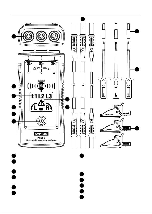
1
Input terminals for L1 (A), L2 (B), L3 (C)
2
Non-contact motor orientation
symbol and sensor indicator
3
Symbol for L1, L2, L3 indicators
4
Symbol for counter-clockwise
rotation
5
Symbol for clockwise rotation
6
“Warning symbol” for false input
voltage
a
a
a
6
Axm
L1/A
L2/B
6
L3/C
xm
6Axm
6
A
12
7
ON symbol for Non-Contact
Rotary Field Indication
and Determine the Motor
Connection
8
ON button / Backlight
9
Test leads (black, red, yellow)
10
Probe tip cap (black, red, yellow)
11
Test probe (black, red, yellow)
12
Alligator clips (black, red, yellow)
2
Page 7
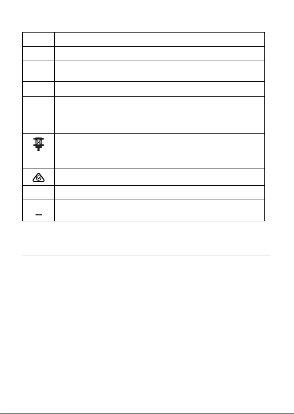
SYMBOLS
Caution! Risk of electric shock.
Caution! Refer to the explanation in this manual.
W
The equipment is protected by double insulation or reinforced
T
insulation
Earth (Ground)
J
Measurement category IV (CAT IV) is for measurement
CAT IV
performed at the source of the low-voltage installation.
Examples are electricity meters and measurement on primary
overcurrent protection device and ripple control units.
Orientation symbol for non-contact motor rotary field
indication.
Complies with European Directives.
P
Conforms to relevant Australian standards
Canadian Standards Association (NRTL/C).
)
Do not dispose of this product as unsorted municipal waste.
=
Contact a qualified recycler.
SAFETY INFORMATION
The meter complies with:
IEC/EN 61557-1/-7
IEC/EN 61010-1 3rd Edition, UL61010-1 3rd Ed. and CAN/CSA C22.2 No. 610101-12 to CAT IV 600 V, pollution degree 2
IEC/EN 61010-2-030
IEC/EN 61010-2-31 for test leads
EMC IEC/EN 61326-1
CENELEC Directives
The instruments conform to CENELEC low-voltage directive 2006/95/EC and
electromagnetic compatibility directive 2004/108/EC.
3
Page 8

W
Warning
To prevent possible electrical shock, fire, or personal injury:
• Carefully read all instructions. Read safety information before using or
servicing the tester.
• Comply with local and national safety codes. Use personal protective
equipment (approved rubber gloves, face protection, and flame resistant
clothes) to prevent shock and arc blast injury where hazardous live
conductors are exposed.
• Use the product only as specified, or the protection supplied by the
product can be compromised.
• Do not work alone.
• Consider mechanical risks and risks of rotating mechanical parts. Comply
with local and national safety codes.
• Do not use the tester or test leads if they appear damaged. Examine the
tester and test leads for damaged insulation or exposed metal. Check
test lead continuity. Replace damaged test leads before using the tester.
• Do not touch voltages >30 V AC RMS, 42 V AC peak, or 60 V DC. These
voltages pose electrical shock hazards. Keep fingers behind the finger
guards on the probes and alligator clips.
• To avoid false readings, which could lead to possible electric shock or
personal injury, check the battery and verify operation beforehand on a
known source.
• Do not exceed the Measurement Category (CAT) rating of the lowest
rated individual component of a product, probe, or accessory.
• If the tester is used in a manner not specified in the users manual, the
protection provided by the equipment may be impaired.
• Measurements can be adversely affected by impedances of additional
operating circuits connected in parallel or by transient currents.
• Do not use the PRM-6 with any of the parts removed.
• Disconnect the test leads from energized circuits and from the tester
before opening the battery cover.
• Do not use the product around explosive gas, vapor, or in damp or wet
environments.
• Have the tester serviced only by qualified service personnel.
• Only use the test lead sets provided with the tester. Alternative test
leads may not fulfill the requirements of EN 61557-7.
4
Page 9

UNPACKING AND INSPECTION
Your shipping carton should include:
1 PRM-6 Motor and Phase Rotation Tester
3 Test leads (black, red, yellow)
3 Test probes (black, red, yellow)
3 Alligator clips (black, red, yellow)
2 1.5V AAA battery (installed)
1 Users manual
1 Carrying case
If any of the items are damaged or missing, return the complete package to
the place of purchase for an exchange.
USING MOTOR AND PHASE ROTATION TESTER
Determine the Rotary Field Direction
To determine the rotary field direction:
1. Connect one end of test leads to the tester’s corresponding terminals L1,
L2, and L3.
2. Connect the alligator clips or the test probes to the other end of the test
leads.
3. Connect the alligator clips/test probes to the three mains phases.
4. L1, L2 and L3 indicators shows voltage is present.
5. The clockwise or counter-clockwise rotary indicator shows the type of
rotary field direction present.
6. If the “Warning Symbol” illuminates, either one or two of the inputs are
connected to the neutral conductor or the voltage difference between
the phases exceed 30% phase to phase or 65% between phase to
neutral.
Note:
• The PRM-6 is powered by the motor or system being tested.
• In environment with poor light condition you can switch on the
Backlight while pressing and hold button “ON” to improve visibility.
W
Warning
The rotary indicator L1, L2 and L3 lights even if the neutral conductor, N, is
connected instead of L1, L2, or L3. Refer to Figure 1 for more information
about what appears on the back of the PRM-6).
5
Page 10
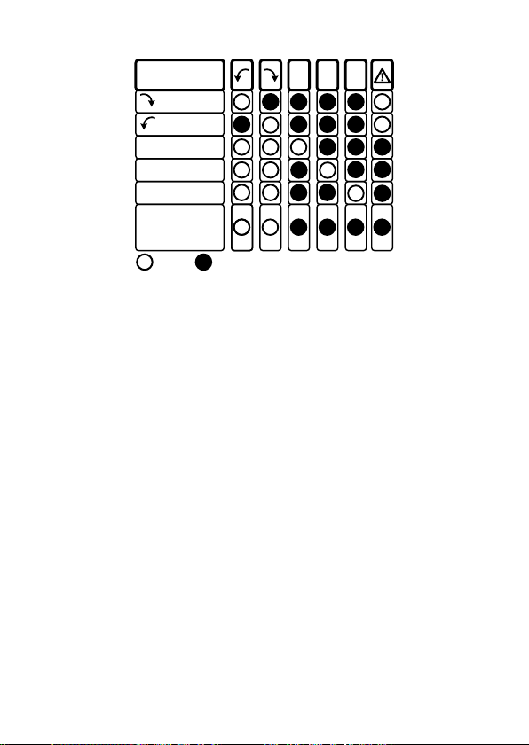
DISPLAY
CORRECT
R
L
FALSE
L R
L1AL2BL3
C
L1 MISSING
L2 MISSING
L3 MISSING
ONE INPUT
CONNECTED
TO N OR PE
OFF ON
Figure 1: Phase indication table
(also printed on the back of the PRM-6)
Non-Contact Rotary Field Indication
For non-contact rotary field indication:
1. Disconnect all test leads from the PRM-6 for safety reason.
2. Position the PRM-6 on the motor so it is parallel to the length of the
motor shaft. The sensor of the tester should be in the center of the
motor windings. The tester should be as close as possible to the motor.
See Figure 2.
3. Press and hold the ON button. The LC display shows “ON,” indicating the
PRM-6 is ready for testing.
4. Either the clockwise or counter-clockwise rotary indicator will illuminate,
showing the type of rotary field direction present.
If the LC display don’t show the “ON” symbol, while pressing the ON button,
the battery does not have a charge and needs to be replaced.
WThe Indicator will not operate with motor controlled by frequency
converters. The bottom of the PRM-6 should be oriented towards the drive
shaft. See the Orientation Symbol on the PRM-6.
If the motor was disconnected from electricity for a long time (typically one
year), the residual field / magnetization may be too weak for the tester to
measure the rotation.
6
Page 11
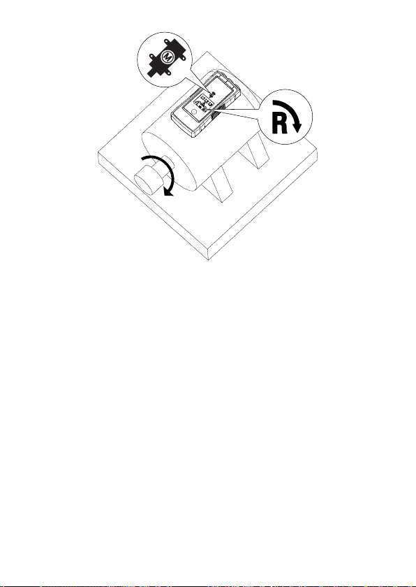
Figure 2: Motor Rotation
Determine the Motor Connection
1. Connect one end of test leads to the tester’s corresponding terminals L1,
L2, and L3.
2. Connect the alligator clips or the test probes to the other end of the test
leads.
3. Connect the alligator clips or test probes to the motor connections, L1 to
U, L2 to V, L3 to W.
4. Press the ON button. The LC display shows “ON,” indicating the PRM-6 is
ready for testing.
5. Turn the motor shaft towards the right.
6. Either the clockwise or counter-clockwise rotary indicator will illuminate,
showing the rotary field direction.
If the LC display don’t show the “ON” symbol, while pressing the ON button,
the battery does not have a charge and needs to be replaced.
Note: If you get a another indication of the rotary field direction as expected
then swap two connection from step 3 and repeat testing. Use the new order
of U (L1), V (L2) and W (L3) for further purpose
7
Page 12
Backlight
The backlight is turned on while pressing and hold button “ON” and it is
powered by the battery.
If the backlight don’t illuminate the battery does not have a charge and
needs to be replaced.
SPECIFICATIONS
3 phase indication
Indication of phase rotation
Indication of motor rotation direction
Non-contact rotary field indication
Determine the motor connection
LC display backlight
Via LCD
Via LCD
Via LCD
Via LCD
Yes
Determine Rotary Field Direction
Frequency range (fn) /
Voltage range (Ume)
Indicaton for false input voltage
Nominal test current (In in per phase)
16...60 Hz / 40...700V AC phase to phase
>60...400 Hz / 50...700V AC phase to
phase
difference of > ±30% between the
phase to phase voltages
(> ± 65% between phase to neutral
voltages)
≤ 3.5 mA
Non-Contact Rotary Field Indication
Frequency range (fn)
16 to 400 Hz
Determine the Motor Connection
Voltage range (Ume)
Frequency range (fn)
≥ 1 V AC phase to phase
2 to 400 Hz
General Specifications
Operating time
Operating temperature
Continuous
O
C to 40OC (32OF to 104OF)
0
8
Page 13
Operating altitude
Humidity (Without condensation)
Storage conditions
Power supply
Battery life
Dust/water resistance
Pollution degree
Dimensions (H x W x D)
Weight
Product Standard
Electrical safety
Overvoltage category
EMC
Agency approvals
Up to 2000 m
≤ 80% RH
O
C to 40OC (32OF to 104OF), ≤ 80% RH
0
2 x 1.5 V AAA alkaline battery
Minimum 2 years for average use
IP 40
2
137 x 65 x 33 mm (5.43 x 2.56 x 1.3 in)
170 g (0.38 lb) (battery installed)
EN 61557 -1/-7
EN 61010-1, EN 61557-7
CAT IV 600 V
Conforms to EN 61326-1
)
P
MAINTENANCE
W
Caution
To prevent damage to the PRM-6:
• Do not attempt to repair or service the PRM-6 unless qualified to do so.
• Make sure that the relevant calibration, performance test, and service
information is being used.
• Do not use abrasives or solvents. Abrasives or solvents will damage the
PRM-6 case.
Cleaning
The only maintenance the PRM-6 requires is inspection and cleaning.
Periodically wipe the case with a mild solution of detergent and water. Apply
sparingly with a soft cloth and allow to dry completely before using. Do not
use aromatic hydrocarbons, gasoline or chlorinated solvents for cleaning.
9
Page 14
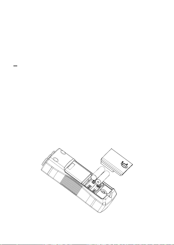
Replacing and Disposing of the Battery
W
Warning
• To avoid electric shock, disconnect the test leads from the source before
opening the PRM-6 for battery replacement.
• To avoid false readings, which could lead to possible electric shock or
personal injury, replace the battery as soon as the battery is low or
dead.
=
Note: The PRM-6 contains alkaline battery. Do not dispose of the battery
with other solid waste.
Used batteries should be disposed of by a qualified recycler or hazardous
materials handler. Contact your authorized Amprobe Service center for
recycling information.
The PRM-6 uses two 1.5 V AAA batteries (supplied). To replace the batteries,
follow these steps and refer to Figure 3:
1. Disconnect test leads from any power source.
2. Place the PRM-6 face down on a nonabrasive surface and loosen the
battery-door lock with a flat screwdriver.
3. Lift the battery cover away from the PRM-6.
4. Replace the batteries as shown in Figure 3. Observe the battery polarity
shown in the battery compartment.
5. Replace the battery cover to the lock position.
AAA
AAA
Figure 3: Replacing batteries
10
Page 15

PRM-6
Medidor de rotación de fase y
motor
Manual de usuario
4/2015, Rev A
©2015 Amprobe Test Tools.
Todos los derechos reservados. Impreso en China
Español
Page 16

Garantía limitada y limitaciones de responsabilidad
El producto Amprobe estará libre de defectos en los materiales y mano de obra durante 1
año a partir de la fecha de compra, a menos que las leyes locales exijan lo contrario. Esta
garantía no cubre fusibles, pilas descartables o daños causados por accidentes, negligencia,
abuso, alteración, contaminación o condiciones anormales de utilización o manipulación. Los
revendedores no están autorizados a extender cualquier otra garantía en representación de
Amprobe. Para recibir servicio técnico durante el período de garantía, devuelva el producto
con el comprobante de compra a un Centro de Servicio Técnico autorizado de Amprobe o a
un distribuidor de Amprobe. Consulte la sección Reparaciones para obtener más información.
ESTA GARANTÍA ES SU ÚNICO RECURSO. POR LA PRESENTE, SE DESCONOCEN TODAS LAS
OTRAS GARANTÍAS, YA SEAN EXPLÍCITAS, IMPLÍCITAS O POR LEY, INCLUIDAS LAS GARANTÍAS
IMPLÍCITAS DE ADECUACIÓN PARA UN PROPÓSITO EN PARTICULAR O COMERCIABILIDAD.
EL FABRICANTE NO SERÁ RESPONSABLE DE DAÑOS O PÉRDIDAS ESPECIALES, INDIRECTOS,
ACCIDENTALES O CONSECUENTES QUE SURJAN DE CUALQUIER CAUSA O TEORÍA. Debido a que
algunos estados o países no permiten la exclusión o limitación de una garantía implícita o de
daños accidentales o consecuentes, esta limitación de responsabilidad podría no aplicarse en su
caso.
Reparaciones
Todos los productos Amprobe devueltos para reparación en garantía o fuera de garantía
o para la calibración deberán estar acompañados de lo siguiente:su nombre, nombre de la
empresa, dirección, número de teléfono y comprobante de compra. Además, incluya una breve
descripción del producto o servicio solicitado e incluya los terminales de prueba con el medidor.
Los gastos por reparaciones o reemplazos fuera de garantía deberán enviarse en forma de
cheque, giro postal, tarjeta de crédito con fecha de vencimiento u orden de compra pagable a
Amprobe.
Reparaciones y reemplazos en garantía (todos los países)
Lea la declaración de garantía e inspeccione las pilas antes de solicitar la reparación. Durante
el período de garantía, cualquier herramienta de prueba defectuosa puede devolverse al
distribuidor de Amprobe para obtener un cambio por un producto igual o similar. Consulte la
sección "Where to Buy" (Lugares de compra) en www.Amprobe.com para obtener una lista
de los distribuidores cercanos. Además, en EE. UU. y Canadá, las unidades de reparación y
reemplazo en garantía también pueden enviarse al Centro de Servicio Técnico de Amprobe
(consulte la dirección que aparece a continuación).
Reparaciones y reemplazos fuera de garantía (EE. UU. y Canadá)
Las reparaciones fuera de garantía en EE. UU. y Canadá deberán enviarse a un Centro de
Servicio Técnico de Amprobe. Comuníquese con Amprobe o consulte en el lugar de compra para
conocer las tarifas actuales de reparación y reemplazo.
EE. UU.: Canadá:
Amprobe Amprobe
Everett, WA 98203 Mississauga, ON L4Z 1X9
Tel.: 877-AMPROBE (267-7623) Tel.: 905-890-7600
Reparaciones y reemplazos fuera de garantía (Europa)
Las unidades fuera de garantía de Europa pueden reemplazarse a través del distribuidor
Amprobe a cambio de una tarifa nominal. Consulte la sección "Where to Buy" (Lugares de
compra) en
Amprobe Europe*
Beha-Amprobe
In den Engematten 14
79286 Glottertal, Alemania
Tel.: +49 (0) 7684 8009 - 0
www.Beha-Amprobe.com
(Sólo correspondencia: ninguna reparación o reemplazo disponible en esta dirección. En el caso de países
europeos, se debe poner en contacto con su distribuidor).
www.Beha-Amprobe.com para obtener una lista de los distribuidores cercanos.
Page 17

Medidor de rotación de fase y motor PRM-6
CONTENIDO
SÍMBOLOS .......................................................................................................... 3
INFORMACIÓN DE SEGURIDAD ........................................................................ 3
DESEMBALAJE E INSPECCIÓN ........................................................................... 5
UTILIZACIÓN DEL MEDIDOR MOTOR Y ROTACIÓN DE FASE .......................... 5
Cómo determinar la dirección del campo de rotación ............................... 5
Indicación de campo de rotación sin contacto ........................................... 6
Cómo determinar la conexión del motor .................................................... 7
Retroiluminación .......................................................................................... 8
ESPECIFICACIONES ............................................................................................ 8
MANTENIMIENTO .............................................................................................. 9
Limpieza ........................................................................................................ 9
Reemplazo y desecho de las pilas ................................................................ 10
1
Page 18

Medidor de rotación de fase y motor PRM-6
9
1
61557-7
61557-7
61557-7
CAT IV 600V
CAT II 1000V
CAT IV 600V
CAT II 1000V
CAT IV 600V
CAT II 1000V
10
11
2
3
4 5
7
8
1
Terminales de entrada para L1 (A),
L2 (B) y L3 (C)
2
Indicador de sensor y símbolo de
orientación de motor sin contacto
3
Símbolo para los indicadores L1, L2
y L3
4
Símbolo de rotación hacia la
izquierda
5
Símbolo de rotación hacia la
derecha
6
"Símbolo de advertencia" para
tensión de entrada falsa
a
a
a
6
Axm
L1/A
L2/B
6
L3/C
xm
6Axm
6
A
12
7
Símbolo "ON" para indicación
de campo de rotación sin
contacto y determinación de la
conexión del motor
8
Botón "ON"/retroiluminación
9
Terminales de prueba (negro,
rojo y amarillo)
10
Tapa de la punta de la sonda
(negra, roja y amarilla)
11
Sonda de prueba (negra, roja y
amarilla)
12
Pinzas de cocodrilo (negras, rojas
y amarillas)
2
Page 19

SÍMBOLOS
¡Precaución! Riesgo de descarga eléctrica.
¡Precaución! Se reere a explicaciones de este manual.
W
Este dispositivo está protegido por un doble aislamiento o
T
aislamiento reforzado
Masa (tierra)
J
La categoría de medición IV (CAT IV) corresponde a la
CAT IV
medición realizada en la fuente de la instalación de baja
tensión. Los ejemplos son los medidores eléctricos y la
medición en dispositivos principales de protección contra
sobrecorrientes y unidades de control de onda.
Símbolo de orientación para la indicación de campo de
rotación de motor sin contacto.
Cumplimiento con las directivas europeas.
P
Cumplimiento con los estándares australianos pertinentes
Asociación de estándares canadienses (NRTL/C).
)
No deseche este producto como un residuo municipal sin
clasicación. Póngase en contacto con un organismo de
=
reciclaje calicado.
INFORMACIÓN DE SEGURIDAD
El medidor cumple con:
IEC/EN 61557-1/-7
IEC/EN 61010-1, 3era edición, UL61010-1, 3era edición y CAN/CSA C22.2 núm.
61010-1-12 a CAT IV 600 V, grado de contaminación 2
IEC/EN 61010-2-030
IEC/EN 61010-2-31 para terminales de prueba
EMC IEC/EN 61326-1
Directivas CENELEC
Los instrumentos cumplen con la directiva de baja tensión CENELEC 2006/95/
EC y la directiva de compatibilidad electromagnética 2004/108/EC.
3
Page 20

W
Advertencia
Para evitar posibles descargas eléctricas, incendios o lesiones personales:
• Lea cuidadosamente todas las instrucciones. Lea la información de
seguridad antes de utilizar o realizar el mantenimiento del medidor.
• Respete los códigos de seguridad locales y nacionales. Utilice equipos
de protección individual (guantes de goma, protección facial y ropa
resistente a la llama aprobados) para evitar lesiones por descargas y
estallidos por arco en aquellas situaciones en las que los conductores
vivos están expuestos.
• Utilice el producto sólo como se especica, o la protección suministrada
por el producto podría verse afectada.
• No trabaje solo.
• Considere los riesgos mecánicos y los riesgos de las piezas mecánicas
giratorias. Respete los códigos de seguridad locales y nacionales.
• No utilice el medidor ni los terminales de prueba si presentan daños.
Examine el medidor y los terminales de prueba para comprobar si existe
un aislamiento dañado o metales expuestos. Inspeccione la continuidad
del terminal de prueba. Reemplace los terminales de prueba dañados
antes de utilizar el medidor.
• No toque las tensiones >30 V de CA RMS, pico de 42 V de CA o 60 V
de CC. Estas tensiones representan un peligro de descarga eléctrica.
Mantenga los dedos detrás de las protecciones para los dedos en las
sondas y pinzas de cocodrilo.
• Para evitar lecturas incorrectas, que podrían derivar en posibles
descargas eléctricas o lesiones personales, inspeccione las pilas y
compruebe el funcionamiento de antemano en una fuente conocida.
• No exceda la clasicación de categoría de medición (CAT) del
componente individual de clasicación más baja de un producto, sonda
o accesorio.
• Si el medidor se usa de una manera que no esté especicada por el
manual de usuario, la protección ofrecida por el producto podría verse
afectada.
• Las mediciones pueden verse afectadas de forma adversa por
impedancias de circuitos en funcionamiento adicionales conectados en
paralelo o por corrientes de compensación.
• No utilice el medidor PRM-6 con alguna pieza extraída.
• Desconecte los terminales de prueba de los circuitos energizados y del
medidor antes de abrir la tapa de las pilas.
• No utilice el producto alrededor de gases explosivos, vapor o en
ambientes húmedos.
• Solicite la reparación del medidor sólo a personal de servicio técnico
calicado.
• Solo utilice los terminales de prueba suministrados con el medidor. Los
terminales de prueba alternativos podrían no cumplir los requisitos de
EN 61557-7.
4
Page 21

DESEMBALAJE E INSPECCIÓN
La caja de cartón de embalaje deberá incluir:
1 Medidor de rotación de fase y motor PRM-6
3 Terminales de prueba (negro, rojo y amarillo)
3 Sondas de prueba (negra, roja y amarilla)
3 Pinzas de cocodrilo (negras, rojas y amarillas)
2 Pila "AAA" de 1,5 V (ya instaladas)
1 Manual de usuario
1 Funda de transporte
Si algunos de estos elementos está dañado o no se encuentra presente,
devuelva la caja de embalaje completa al lugar de compra para obtener un
cambio.
UTILIZACIÓN DEL MEDIDOR DE ROTACIÓN DE FASE Y MOTOR
Cómo determinar la dirección del campo de rotación
Para determinar la dirección del campo de rotación:
1. Conecte un extremo de los terminales de prueba a los terminales L1, L2 y
L3 correspondientes del medidor.
2. Conecte las pinzas de cocodrilo o las sondas de prueba en el otro
extremo de los terminales de prueba.
3. Conecte las las pinzas de cocodrilo/sondas de prueba en las 3 fases de
corriente.
4. Los indicadores L1, L2 y L3 muestran que existe presente tensión.
5. El indicador de rotación hacia la derecha o izquierda muestra el tipo de
dirección de campo de rotación presente.
6. Si se enciende el “símbolo de advertencia”, una o dos de las entradas
están conectadas al conductor neutro o la diferencia de tensión entre las
fases excede el 30% de fase a fase o el 65% entre fase y neutro.
Nota:
• El medidor PRM-6 se alimenta a través del motor o sistema que se está
sometiendo a pruebas.
• En un ambiente con una condición de iluminación deciente, puede
activar la retroiluminación manteniendo presionando el botón "ON" a
n de mejorar la visibilidad.
W
Advertencia
El indicador de rotación L1, L2 y L3 se enciende incluso si el conductor
neutro "N" está conectado en lugar de L1, L2 o L3. Consulte la figura 1
para obtener más información sobre qué aparece en la parte posterior del
medidor PRM-6).
5
Page 22

DISPLAY
CORRECT
R
L
FALSE
L R
L1AL2BL3
C
L1 MISSING
L2 MISSING
L3 MISSING
ONE INPUT
CONNECTED
TO N OR PE
OFF ON
Figura 1: Tabla de indicación de fase
(también impresa en la parte posterior del medidor PRM-6)
Indicación de campo de rotación sin contacto
Para indicación de campo de rotación sin contacto:
1. Por razones de seguridad, desconecte todos los terminales de prueba del
medidor PRM-6.
2. Coloque el medidor PRM-6 en el motor de forma tal que quede paralelo
a la longitud del eje del motor. El sensor del medidor deberá estar en el
centro de los bobinados del motor. El medidor deberá estar lo más cerca
posible del motor. Consulte la gura 2.
3. Mantenga presionado el botón "ON". La pantalla LCD muestra "ON", lo
que indica que el medidor PRM-6 está listo para las pruebas.
4. Se encenderá el indicador de rotación hacia la derecha o izquierda, lo
que indica el tipo de dirección de campo de rotación presente.
Si la pantalla LCD no muestra el símbolo "ON" mientras presiona el botón
"ON", las pilas no tienen carga y es necesario reemplazarlas.
W El indicador no funcionará con un motor controlado con convertidores
de frecuencia. La parte inferior del medidor PRM-6 deberá estar orientada
hacia el eje impulsor. Consulte el símbolo de orientación en el medidor
PRM-6.
Si el motor estuvo desconectado de la electricidad durante un tiempo
extenso (generalmente 1 año), el campo residual/magnetización podría ser
demasiado débil para que el medidor pueda calcular la rotación.
6
Page 23

Figura 2: Rotación del motor
Cómo determinar la conexión del motor
1. Conecte un extremo de los terminales de prueba a los terminales L1, L2 y
L3 correspondientes del medidor.
2. Conecte las pinzas de cocodrilo o las sondas de prueba en el otro
extremo de los terminales de prueba.
3. Conecte las pinzas de cocodrilo o sondas de prueba en las condiciones
del motor (L1 a U, L2 a V, L3 a W).
4. Presione el botón "ON". La pantalla LCD muestra "ON", lo que indica
que el medidor PRM-6 está listo para las pruebas.
5. Gire el eje del motor hacia la derecha.
6. Se encenderá el indicador de rotación hacia la derecha o izquierda, lo
que indica la dirección del campo de rotación.
Si la pantalla LCD no muestra el símbolo "ON" mientras presiona el botón
"ON", las pilas no tienen carga y es necesario reemplazarlas.
Nota: Si obtiene otra indicación de rotación del campo de dirección que
la esperada, cambie las 2 conexiones desde el paso 3 y vuelva a repetir la
prueba. Utilice el orden nuevo de U (L1), V (L2) y W (L3) para otra nalidad.
7
Page 24

Retroiluminación
La retroiluminación se enciende al mantener presionado el botón "ON" y
está alimentada por las pilas.
Si la retroiluminación no se enciende, las pilas no tienen carga y es necesario
reemplazarlas.
ESPECIFICACIONES
Indicación trifásica A través de la pantalla LCD
Indicación de la rotación de fase A través de la pantalla LCD
Indicación de dirección de
rotación del motor
Indicación de campo de rotación
sin contacto
Cómo determinar la conexión
del motor
Retroiluminación de la pantalla
LCD
A través de la pantalla LCD
A través de la pantalla LCD
Sí
Cómo determinar la dirección del campo de rotación
Rango de frecuencia (fn) /
Rango de tensión (Ume)
Indicador de tensión de entrada
falsa
Corriente de prueba nominal
(por fase)
16...60 Hz / 40...700 V de CA (fase a fase)
>60...400 Hz / 50...700 V de CA (fase a
fase)
Diferencia de > ±30% entre las tensiones
de fase a fase
(> ± 65% entre las tensiones de fase a
neutro)
≤ 3,5 mA
Indicación de campo de rotación sin contacto
Rango de frecuencia (fn) De 16 a 400 Hz
Cómo determinar la conexión del motor
Rango de tensión (Ume)
Rango de frecuencia (fn) De 2 a 400 Hz
≥ 1 V de CA (fase a fase)
Especificaciones generales
Tiempo de funcionamiento Continuo
Temperatura de funcionamiento De
O
C a 40OC (de 32OF a 104OF)
8
Page 25

Altitud de funcionamiento Hasta 2000 metros
Humedad (sin condensación)
Condicionales de
almacenamiento
Fuente de alimentación 2 pilas alcalinas "AAA" de 1,5 V
Vida útil de las pilas Mínimo 2 años para uso promedio
Resistencia a polvo/agua IP 40
Grado de contaminación 2
Dimensiones (alto x ancho x
profundidad)
Peso 170 gramos (0,38 libras) (con pilas)
Estándar del producto EN 61557 -1/-7
Seguridad eléctrica EN 61010-1, EN 61557-7
Categoría de sobretensión CAT IV de 600 V
EMC Cumplimiento con EN 61326-1
Aprobación de agencias
≤ 80% (humedad relativa)
O
C a 40OC (de 32OF a 104OF), ≤ 80%
De
(humedad relativa)
137 x 65 x 33 mm (5,43" x 2,56" x 1,3")
)
P
MANTENIMIENTO
W
Precaución
Para evitar daños al medidor PRM-6:
• No intente reparar o realizar el mantenimiento de medidor PRM-6 a
menos que posea las calificaciones para hacerlo.
• Asegúrese de que se utilice la calibración, prueba de rendimiento e
información de rendimiento correctas.
• No utilice abrasivos o solventes. Los abrasivos o solventes provocarán
daños en la cubierta del medidor PRM-6.
Limpieza
El único mantenimiento que el medidor PRM-6 requiere es la inspección y
la limpieza. Limpie periódicamente la cubierta con una solución neutra de
detergente y agua. Aplique pequeñas cantidades con un paño suave y espere
a que se seque por completo antes de utilizar. No utilice hidrocarburos
aromáticos, gasolina o solvente clorinados para efectuar la limpieza.
9
Page 26

Reemplazo y desecho de las pilas
W
Advertencia
• Para evitar descargas eléctricas, desconecte los terminales de prueba de
la fuente de energía antes de abrir el medidor PRM-6 para el reemplazo
de las pilas.
• Para evitar lecturas incorrectas, que podrían causar posibles descargas
eléctricas o lesiones personales, reemplace las pilas ni bien posean una
carga baja o están agotadas por completo.
=
Nota: El medidor PRM-6 incluye pilas alcalinas. No deseche las pilas con
otros residuos sólidos.
Las pilas usadas deberán ser desechadas por un reciclador o manipulador
de materiales peligrosos calificado. Póngase en contacto con el centro de
servicio técnico autorizado de Amprobe para obtener información sobre el
reciclaje.
El medidor PRM-6 utiliza 2 pilas "AAA" de 1,5 V (suministradas). Para
reemplazar las pilas, siga estos pasos y consulte la gura 3:
1. Desconecte los terminales de prueba de cualquier fuente de energía.
2. Coloque el medidor PRM-6 hacia abajo sobre una supercie no abrasiva
y aoje el bloqueo de la tapa de las pilas con un destornillador plano.
3. Levante y extraiga la tapa de las pilas del medidor PRM-6.
4. Reemplace las pilas, tal como se muestra en la gura 3. Observe la
polaridad de las pilas, tal como se muestra en el compartimiento de las
pilas.
5. Vuelva a colocar la tapa de las pilas en la posición de bloqueo.
AAA
AAA
Figura 3: Reemplazo de las pilas
10
Page 27

PRM-6
Testeur de rotation de phase
et de moteur
Manuel de l’utilisateur
4/2015, Rev A
©2015 Amprobe Test Tools.
Tous droits réservés. Imprimé en Chine
Français
Page 28

Garantie limitée et limitation de responsabilité
Votre produit Amprobe sera exempt de défauts de matériaux et de fabrication pendant un
(1) an à compter de la date d'achat, sauf exigence contraire en vertu de la juridiction locale.
Cette garantie ne s'applique pas aux fusibles, aux piles jetables ou endommagées par accident,
à la négligence, à la mauvaise utilisation, à l'altération, à la contamination ou aux conditions
anormales d'utilisation ou de manipulation. Les revendeurs ne sont pas autorisés à prolonger
toute autre garantie au nom de Amprobe. Pour une réparation au cours de la période de
garantie, retournez le produit avec la preuve d'achat à un centre de service autorisé par
Amprobe ou à un revendeur ou un distributeur Amprobe. Voir la section Réparation pour
plus de détails. CETTE GARANTIE EST VOTRE SEUL RECOURS. TOUTES LES AUTRES GARANTIES
– QU'ELLES SOIENT EXPLICITES, IMPLICITES OU JURIDIQUES – Y COMPRIS LES GARANTIES
IMPLICITES D'ADAPTATION À UN USAGE PARTICULIER OU MARCHAND, SONT EXCLUES. LE
FABRICANT NE SERA PAS RESPONSABLE DES DOMMAGES SPECIAUX, INDIRECTS, ACCESSOIRES
OU CONSECUTIFS PROVENANT DE TOUTE CAUSE OU THEORIE. Etant donné que certains pays
ou états n'autorisent pas l'exclusion ou la limitation des garanties implicites ou des dommages
directs ou indirects, cette limitation de responsabilité peut ne pas s'appliquer à vous.
Réparation
Tout produit Amprobe retourné pour réparation sous garantie ou hors garantie ou pour
l'étalonnage doit être accompagné des documents suivants :votre nom, le nom de votre société,
votre adresse, votre numéro de téléphone et la preuve d'achat. De plus, veuillez inclure une
brève description du problème ou du service demandé et incluez les cordons de mesure avec
le compteur. Les frais de réparation ou de remplacement non garantis doivent être réglés sous
forme de chèque, mandat, carte de crédit avec date d'expiration ou bon de commande payable
à Amprobe.
Réparation et remplacement couverts par la garantie – Tous les pays
Veuillez lire la déclaration de garantie et vérifier la pile avant de demander une réparation.
Pendant la période de garantie, tout outil de vérification défectueux peut être retourné à votre
distributeur Amprobe pour un échange de produit identique ou similaire. Veuillez consulter la
section « Où acheter » sur le site www.Amprobe.com pour obtenir une liste des distributeurs
près de chez vous. En outre, aux États-Unis et au Canada, les réparations sous garantie et les
unités de remplacement peuvent également être envoyés à un centre de service Amprobe (voir
adresse ci-dessous).
Réparation et remplacement non couverts par la garantie – États-Unis et Canada
Pour les réparations non couvertes par la garantie aux États-Unis et au Canada, l'appareil doit
être envoyé à un centre de service Amprobe. Appelez Amprobe ou renseignez-vous auprès de
votre point de vente pour les tarifs de réparation et de remplacement actuels.
États-Unis : Canada :
Amprobe Amprobe
Everett, WA 98203 Mississauga (Ontario) L4Z 1X9
Tél. : 877-AMPROBE (267-7623) Tél. : 905-890-7600
Réparation et remplacement non couverts par la garantie – Europe
Les unités hors garantie européenne peuvent être remplacées par votre distributeur
Amprobe pour une somme modique. Veuillez consulter la section « Où acheter » sur le site
www.Beha-Amprobe.com pour obtenir une liste des distributeurs près de chez vous.
Amprobe Europe*
Beha-Amprobe
In den Engematten 14
79286 Glottertal, Allemagne
Tél. : +49 (0) 7684 8009 - 0
www.Beha-Amprobe.com
*
(Correspondance uniquement : aucune réparation ou remplacement à cette adresse. Clients européens,
veuillez contacter votre distributeur.)
Page 29

Testeur de rotation de phase et de moteur PRM-6
TABLE DES MATIÈRES
SYMBOLE ........................................................................................................... 3
CONSIGNES DE SÉCURITÉ ................................................................................. 3
DÉBALLAGE ET INSPECTION ............................................................................. 5
UTILISATION DU TESTEUR D'ORDRE DE PHASES ET DE ROTATION
MOTEUR ............................................................................................................. 5
Déterminer la direction du champ de rotation .......................................... 5
Indication du champ de rotation sans contact ........................................... 6
Déterminer la connexion du moteur ........................................................... 7
Rétroéclairage............................................................................................... 8
SPÉCIFICATIONS ................................................................................................. 8
ENTRETIEN ......................................................................................................... 9
Nettoyage ..................................................................................................... 9
Remplacement et mise au rebut de la pile ................................................. 10
1
Page 30

Testeur de rotation de phase et de moteur PRM-6
9
CAT IV 600V
1
CAT II 1000V
61557-7
61557-7
61557-7
CAT IV 600V
CAT II 1000V
CAT IV 600V
CAT II 1000V
10
11
2
3
4 5
7
8
1
Bornes d'entrée de L1 (A), L2 (B),
L3 (C)
2
Indicateur du capteur et symbole
d'orientation du moteur sans
contact
3
Symbole des indicateurs L1, L2, L3
4
Symbole de rotation antihoraire
5
Symbole de rotation horaire
6
« Symbole d'avertissement » pour
tension d'entrée erronée
a
a
a
6
Axm
L1/A
L2/B
6
L3/C
xm
6Axm
6
A
12
7
Symbole MARCHE pour
indication du champ de rotation
sans contact et déterminer la
connexion du moteur
8
Bouton MARCHE / Rétroéclairage
9
Câbles d'essai (noir, rouge, jaune)
10
Capuchon de la pointe de la
sonde (noir, rouge, jaune)
11
Sonde d'essai (noir, rouge, jaune)
12
Pinces crocodile (noir, rouge,
jaune)
2
Page 31

SYMBOLES
Attention! Risque de choc électrique.
Attention! Reportez-vous aux explications de ce guide.
W
Cet équipement est protégé par une isolation double ou
T
renforcée
Prise de terre
J
La catégorie de mesure IV (CAT IV) est prévue pour les mesures
CAT IV
effectuées à la source d'une installation à faible tension.
Ceci comprend par exemple les compteurs d'électricité et les
mesures sur des appareils de protection contre la surtension
primaires ainsi que les récepteurs de commandes.
Symbole d'orientation pour indication du champ de rotation
moteur sans contact.
Conforme aux directives européennes.
P
Conforme aux normes australiennes pertinentes.
Association canadienne de normalisation (NRTL/C).
)
Ne jetez pas ce produit avec les déchets municipaux non triés.
=
Contactez un recycleur qualifié.
CONSIGNES DE SÉCURITÉ
L'appareil de mesure est conforme à :
IEC/EN 61557-1/-7
IEC/EN 61010-1 3e Édition, UL61010-1 3e Éd. et CAN/CSA C22.2 No. 61010-1-
12 à CAT IV 600 V, degré de pollution 2
IEC/EN 61010-2-030
IEC/EN 61010-2-31 pour les prises de test
EMC IEC/EN 61326-1
Directives CENELEC
Les instruments sont conformes à la directive basse tension CENELEC
2006/95/CE et la directive de compatibilité électromagnétique 2004/108/CE.
3
Page 32

W
Avertissement
Pour éviter tout risque d'électrocution, de brûlure ou de blessure :
• Lisez attentivement toutes les instructions. Lisez les informations de
sécurité avant d'utiliser ou de réparer le testeur.
• Conformez-vous aux normes locales et nationales de sécurité. Utilisez
de l'équipement de protection personnelle (gants en caoutchouc
approuvés, protection faciale, vêtements ignifuges) pour éviter les
chocs et les blessures lorsque des conducteurs en fonctionnement sont
exposés.
• Utilisez le produit seulement comme indiqué, ou la protection fournie
par le produit pourrait être compromise.
• Ne travaillez pas seul.
• Prenez en compte les risques mécaniques et les risques de rotation des
pièces mécaniques. Conformez-vous aux normes locales et nationales de
sécurité.
• N'utilisez pas le testeur ou des prises de test s'ils sont endommagés.
Examinez le testeur et les prises de test pour vérifier la présence
d'isolation endommagée ou de métal exposé. Vérifiez la continuité des
prises de test. Remplacez les câbles d'essai endommagés avant d'utiliser
le testeur.
• Ne touchez pas des objets à tension > 30 V CA RMS, 42 V CA crête ou
60 V CC. Ces tensions posent des risques de choc électrique. Gardez vos
doigts derrière les protections sur les sondes et les pinces crocodile.
• Pour éviter les lectures erronées, qui peuvent entraîner une décharge
électrique ou des blessures physiques, contrôlez la pile et vérifiez à
l'avance le fonctionnement sur une source connue.
• Ne dépassez pas le catégorie de mesure (CAT) du composant à catégorie
la plus faible d'un produit, d'une sonde ou d'un accessoire.
• Si le testeur est utilisé d'une manière non spécifiée par le manuel de
l'utilisateur, la protection fournie par l'équipement peut être altérée.
• Les mesures peuvent être affectées négativement par des impédances
causées par des circuits supplémentaires connectés en parallèle ou par
des courants d'équilibrage.
• N'utilisez pas le PRM-6 avec des pièces retirées.
• Débranchez les câbles d'essai des circuits sous tension et du testeur avant
d'ouvrir le couvercle des piles.
• N'utilisez pas la produit près d'environnements à gaz explosifs, à vapeur
ou humides.
• Seul du personnel qualifié peut se charger de l'entretien du testeur.
• Utilisez uniquement les ensembles de câbles d'essai fournis avec le
testeur. D'autres câbles d'essai peuvent ne pas respecter les exigences
d'EN 61557-7.
4
Page 33

DÉBALLAGE ET INSPECTION
Votre emballage doit contenir :
1 Testeur de rotation de phase et de moteur PRM-6
3 Câbles d'essai (noir, rouge, jaune)
3 Sondes d'essai (noir, rouge, jaune)
3 Pinces crocodile (noir, rouge, jaune)
2 Pile AAA 1,5V (installée)
1 guide d'utilisation
1 Mallette de transport
Si l'un de ces éléments est manquant ou endommagé, retournez l'emballage
complet à votre point d'achat pour un échange.
UTILISATION DU TESTEUR DE ROTATION DE PHASE ET DE MOTEUR
Déterminer la direction du champ de rotation
Pour déterminer la direction du champ de rotation :
1. Branchez une extrémité des câbles d'essai aux bornes L1, L2 et L3
correspondantes du testeur.
2. Branchez les pinces crocodile ou les sondes d'essai sur l'autre extrémité
des câbles d'essai.
3. Branchez les pinces crocodile/les sondes d'essai sur les trois phases
secteur.
4. Les indicateurs L1, L2 et L3 indiquent si la tension est présente.
5. L'indicateur de rotation horaire ou antihoraire indique le type de
direction de champ de rotation présent.
6. Si le « symbole d’avertissement » s’allume, une ou deux entrées sont
raccordées au conducteur neutre ou la différence de tension entre les
phases dépasse 30 % phase à phase ou 65 % entre la phase et le neutre.
Remarque :
• Le PRM-6 est alimenté par le moteur ou le système à l'essai.
• Dans un environnement avec des conditions de faible luminosité, vous
pouvez activer le rétroéclairage en appuyant et en maintenant le
bouton « MARCHE » enfoncé pour améliorer la visibilité.
W
Avertissement
L'indicateur de rotation L1, L2 et L3 s'éclaire même si le conducteur neutre,
N, est branché au lieu de L1, L2 ou L3. Consultez la Figure 1 pour de plus
amples informations sur ce qui apparaît à l'arrière du PRM-6).
5
Page 34

DISPLAY
CORRECT
R
L
FALSE
L R
L1AL2BL3
C
L1 MISSING
L2 MISSING
L3 MISSING
ONE INPUT
CONNECTED
TO N OR PE
OFF ON
Figure 1 : Tableau d'indication des phases
(également imprimé à l'arrière du PRM-6)
Indication du champ de rotation sans contact
Pour l'indication du champ de rotation sans contact :
1. Débranchez tous les câbles d'essai du PRM-6 pour des raisons de sécurité.
2. Positionnez le PRM-6 sur le moteur afin qu'il soit parallèle à la longueur
de l'arbre du moteur. Le capteur du testeur doit être au centre du
bobinage du moteur. Le testeur doit être aussi proche que possible du
moteur. Voir Figure 2.
3. Appuyez sur le bouton MARCHE et maintenez-le enfoncé. L'écran LCD
affiche « MARCHE » pour indiquer que le PRM-6 est prêt pour les essais.
4. L'indicateur de rotation horaire ou antihoraire s'éclaire pour afficher le
type de direction de champ de rotation présent.
Si l'écran LCD n'affiche pas le symbole « MARCHE » en appuyant sur le
bouton MARCHE, la pile n'a pas de charge et doit être remplacée.
WL'indicateur ne fonctionnera pas avec le moteur contrôlé par des
convertisseurs de fréquence. Le bas du PRM-6 doit être orienté en direction
de l'arbre de transmission. Voir le symbole d'orientation sur le PRM-6.
Si le moteur a été débranché de l'alimentation électrique pendant une
longue période (généralement un an), le champ/la magnétisation résiduels
peuvent être trop faibles pour que le testeur puisse mesurer la rotation.
6
Page 35

Figure 2 : Rotation moteur
Déterminer la connexion du moteur
1. Branchez une extrémité des câbles d'essai aux bornes L1, L2 et L3
correspondantes du testeur.
2. Branchez les pinces crocodile ou les sondes d'essai sur l'autre extrémité
des câbles d'essai.
3. Connectez les pinces crocodile ou les sondes d'essai aux connexions du
moteur, L1 sur U, L2 sur V, L3 sur W.
4. Appuyez sur le bouton MARCHE. L'écran LCD affiche « MARCHE » pour
indiquer que le PRM-6 est prêt pour les essais.
5. Tournez l'arbre du moteur vers la droite.
6. L'indicateur de rotation horaire ou antihoraire s'éclaire pour afficher la
direction du champ de rotation.
Si l'écran LCD n'affiche pas le symbole « MARCHE » en appuyant sur le
bouton MARCHE, la pile n'a pas de charge et doit être remplacée.
Remarque : Si vous obtenez une autre indication que celle attendue pour la
direction du champ de rotation, échangez les deux raccordements de l'étape
3 et recommencez l'essai. Utilisez le nouvel ordre de U (L1), V (L2) et W (L3)
à d'autres fins
7
Page 36

Rétroéclairage
Le rétroéclairage est activé en appuyant et en maintenant le bouton
« MARCHE » enfoncé. Il est alimenté par la pile.
Si le rétroéclairage ne s'allume pas, la pile n'a pas de charge et doit être
remplacée.
SPÉCIFICATIONS
Indication des 3 phases
Indication de la rotation de
phase
Indication de la direction de
rotation du moteur
Indication du champ de rotation
sans contact
Déterminer la connexion du
moteur
Rétroéclairage de l'écran LCD
Par LCD
Par LCD
Par LCD
Par LCD
Oui
Déterminer la direction du champ de rotation
Plage de fréquence (fn) /
Plage de tensions (Ume)
Indication de tension d'entrée
erronée
Courant de test nominal (par
phase)
16...60 Hz / 40...700 V CA phase à phase
> 60...400 Hz / 50...700 V CA phase à
phase
différence de > ±30 % entre les tensions
de phase à phase
(> ± 65 % entre les tensions de phase à
neutre)
≤ 3,5 mA
Indication du champ de rotation sans contact
Plage de fréquence (fn)
16 à 400 Hz
Déterminer la connexion du moteur
Plage de tensions (Ume)
Plage de fréquence (fn)
≥ 1 V CA phase à phase
2 à 400 Hz
Caractéristiques générales
Durée de fonctionnement
Température d'utilisation
Continue
O
C à 40OC (32OF à 104OF)
0
8
Page 37

Altitude d'utilisation
Humidité (sans condensation)
Conditions de stockage
Alimentation
Durée de vie de la pile
Résistance à la poussière et l'eau
Degré de pollution
Dimensions (H x L x P)
Poids
Norme du produit
Sécurité électrique
Catégorie de surtension
Compatibilité électromagnétique
Approbations d'agences
Jusqu'à 2 000 m
≤ 80 % RH
O
C à 40OC (32OF à 104OF), ≤ 80 % RH
0
2 x piles alcalines AAA 1,5 V
Au moins 2 ans pour une utilisation
normale
IP 40
2
137 x 65 x 33 mm (5,43 x 2,56 x 1,3 po)
170 g (0,17 kg) (pile installée)
EN 61557 -1/-7
EN 61010-1, EN 61557-7
CAT IV 600 V
Conforme à EN 61326-1
)
P
MAINTENANCE
W
Attention
Pour éviter d'endommager le PRM-6 :
• Ne tentez pas de réparer le PRM-6 à moins d'avoir les qualifications
nécessaires.
• Vérifiez que les bons calibrage, test de performance et informations de
service sont utilisés.
• N'utilisez pas de matières abrasives ou de solvants. Les matières
abrasives et solvants peuvent endommager le boîtier du PRM-6.
Nettoyage
La seule maintenance requise par le PRM-6 est l'inspection et le nettoyage.
Essuyez régulièrement l'étui avec une solution neutre d'eau et de détergent.
Appliquer en petite quantité avec un chiffon doux et laisser sécher
complètement avant utilisation. Ne pas utiliser d'hydrocarbures aromatiques,
d'essence ou de solvants chlorés pour le nettoyage.
9
Page 38

Remplacement et mise au rebut de la pile
W
Avertissement
• Pour éviter les chocs électriques, débranchez les prises de test de la
source avant d'ouvrir le PRM-6 pour remplacer les piles.
• Pour éviter les mauvaises lectures, qui peuvent causer des chocs
électriques ou des blessures personnelles, remplacez la pile dès que
celle-ci est faible.
=
Remarque : Le PRM-6 contient des piles alcalines. Ne jetez pas la pile avec
d'autres ordures solides.
Les piles usées doivent être mises au rebut par un recycleur qualifié ou un
responsable des matériaux dangereux. Contactez votre centre de service
Amprobe agréé pour des informations sur le recyclage.
Le PRM-6 utilise deux piles AAA 1,5 V (fournies). Pour remplacer les piles,
suivez ces étapes et consultez la Figure 3 :
1. Débranchez les prises de test des sources d'alimentation.
2. Placez le PRM-6 face tournée vers le bas sur une surface non abrasive et
déverrouillez le couvercle des piles avec un tournevis plat.
3. Retirez le couvercle des piles du PRM-6.
4. Remplacez la pile comme indiqué en Figure 3. Suivez les polarités
affichées dans le compartiment de la pile.
5. Replacez le couvercle des piles en position verrouillée.
AAA
AAA
Figure 3 : Remplacement des piles
10
Page 39

PRM-6
Testador de Rotação e Fase de
Motor
Manual dos Usuários
4/2015, Rev A
©2015 Amprobe Test Tools.
Todos os direitos reservados. Impresso na China
Português
Page 40

Garantia Limitada e Limitação de Responsabilidade
Seu produto Amprobe estará livre de defeitos de material e mão de obra por um ano a partir
da data da compra, a menos que as leis locais exijam de outra forma. Esta garantia não cobre
fusíveis, pilhas descartáveis ou danos decorrentes de acidentes, negligência, mau uso, alteração,
contaminação ou condições anormais de operação ou manuseio. Os revendedores não estão
autorizados a conceder nenhuma outra garantia em nome da Amprobe. Para obter o serviço
durante o período de garantia, devolva o produto com o comprovante de compra para um
Centro de Assistência Técnica Amprobe ou a um revendedor ou distribuidor Amprobe. Consulte
a Seção de Reparo para detalhes. ESTA GARANTIA É O ÚNICO RECURSO. TODAS AS OUTRAS
GARANTIAS - SEJAM EXPRESSAS, IMPLÍCITAS OU ESTATUTÁRIAS - INCLUINDO AS GARANTIAS
DE ADEQUAÇÃO A UM DETERMINADO FIM OU DE COMERCIALIZAÇÃO, SÃO RENUNCIADAS. O
FABRICANTE NÃO SERÁ RESPONSÁVEL POR QUAISQUER DANOS OU PERDA ESPECIAL, INDIRETA,
ACIDENTAL OU CONSEQUENTE, DECORRENTE DE QUALQUER CAUSA OU TEORIA. Como alguns
estados ou países não permitem a exclusão ou limitação de uma garantia implícita ou de danos
incidentais ou consequentes, esta limitação de responsabilidade pode não se aplicar a você.
Reparo
Tudo da Amprobe devolvido para reparação de garantia ou não de garantia ou para a
calibração deve ser acompanhado dos seguintes elementos: o seu nome, o nome da empresa,
endereço, número de telefone e comprovante de compra. Além disso, inclua uma breve
descrição do problema ou o serviço solicitado e inclua os terminais de teste com o medidor.
Despesas de reparo ou substituição de não garantia devem ser enviadas em forma de um
cheque, uma ordem de pagamento, cartão de crédito com data de validade ou uma ordem de
compra a pagar para a Amprobe.
Reparos e substituição em garantia - Todos os países
Por favor, leia a declaração de garantia e verique sua bateria antes de solicitar reparo. Durante
o período de garantia, qualquer ferramenta de teste com defeito pode ser devolvida ao seu
distribuidor Amprobe para uma troca pelo mesmo produto ou similar. Por favor, verique a
seção "Onde Comprar" na www.Amprobe.com para uma lista de distribuidores perto de você.
Além disso, nos Estados Unidos e no Canadá, unidades de reparação e substituição em garantia
também podem ser enviadoas para um Centro de Serviço Amprobe (ver endereço abaixo).
Reparos e substituição fora de garantia - Estados Unidos e Canadá
Reparos fora da garantia nos Estados Unidos e no Canadá devem ser enviados para um Centro
de Serviço Amprobe. Ligue para a Amprobe ou pergunte no seu ponto de compra pelas taxas de
reparo e substituição atuais.
EUA: Canadá:
Amprobe Amprobe
Everett, WA 98203 Mississauga, ON L4Z 1X9
Tel: 877-AMPROBE (267-7623) Tel: 905-890-7600
Reparos e substituição fora de garantia - Europa
Unidades europeias fora de garantia podem ser substituídas por seu distribuidor Amprobe
por uma taxa nominal. Por favor, verique a seção "Onde Comprar"
com
para uma lista de distribuidores perto de você.
Amprobe Europa*
Beha-Amprobe
In den Engematten 14
79286 Glottertal, Alemanha
Tel.: +49 (0) 7684 8009 - 0
www.Beha-Amprobe.com
*
(Correspondência apenas - nenhum reparo ou substituição disponível neste endereço. Clientes europeus
favor entrar em contato com seu distribuidor.)
www.Beha-Amprobe.
Page 41

PRM-6 Testador de Rotação e Fase de Motor
ÍNDICE
SÍMBOLO ............................................................................................................ 3
INFORMAÇÕES DE SEGURANÇA ...................................................................... 3
DESEMBALAGEM E INSPEÇÃO ......................................................................... 5
USANDO TESTEADPR DE SEQUÊNCIA DE FASE E ROTAÇÃO DO MOTOR ..... 5
Determinar a Direção de Campo de Rotação ............................................. 5
Indicação de Campo de Rotação Sem-Contato ........................................... 6
Determinar a Conexão Motor ...................................................................... 7
Luz de Fundo ................................................................................................ 8
ESPECIFICAÇÕES ................................................................................................ 8
MANUTENÇÃO .................................................................................................. 9
Limpeza ......................................................................................................... 9
Substituição e Eliminação da Bateria .......................................................... 10
1
Page 42

PRM-6 Testador de Rotação e Fase de Motor
9
1
61557-7
61557-7
61557-7
CAT IV 600V
CAT II 1000V
CAT IV 600V
CAT II 1000V
CAT IV 600V
CAT II 1000V
10
11
2
3
4 5
7
8
1
Terminais de entrada para L1 (A),
L2 (B), (C) L3
2
Símbolo de orientação e sensor
indicador do motor sem contato
3
Símbolo para indicadores L1, L2, L3
4
Símbolo para a rotação no sentido
anti-horário
5
Símbolo para a rotação no sentido
horário
6
"Símbolo de advertência" para
tensão de entrada falsa
a
a
a
6
Axm
L1/A
L2/B
6
L3/C
xm
6Axm
6
A
12
7
Símbolo ON (Ligado) para
Indicação de Campo Rotativo
Sem Contato e Determinar a
Conexão do Motor
8
Botão ON (Liga) / Luz de Fundo
9
Pontas de prova (preta, vermelha,
amarela)
10
Ponteira da sonda (preta,
vermelha, amarela)
11
Sonda de prova (preta, vermelha,
amarela)
12
Alicates (preto, vermelho,
amarelo)
2
Page 43

SÍMBOLOS
Cuidado! Risco de choque elétrico.
Cuidado! Consulte a explicação neste manual.
W
O equipamento é protegido por duplo isolamento ou
T
isolamento reforçado.
Aterramento.
J
A categoria de medição IV (CAT IV) é para medições realizadas
CAT IV
na fonte da instalação de baixa tensão. Exemplos são
medidores de eletricidade e de medição no dispositivo de
proteção de sobrecorrente primária e unidades de controle de
ondulação.
Símbolo de orientação para indicação de campo rotativo do
motor sem-contato.
Está em conformidade com as Diretivas Europeias.
P
Conformidade com os padrões relevantes da Austrália
Associuação de Normas Canadenses (NRTL/C).
)
Não descarte este produto como resíduo urbano não
=
classicado. Contate um reciclador qualicado.
INFORMAÇÕES DE SEGURANÇA
O medidor está em conformidade com:
IEC/EN 61557-1/-7
IEC/EN 61010-1 3ª Edição, UL61010-1 3ª Ed. e CAN/CSA C22.2 N. 61010-1-12
para CAT IV 600 V, grau de poluição 2
IEC/EN 61010-2-030
IEC/EN 61010-2-31 para cabos de teste
EMC IEC/EN 61326-1
Diretivas CENELEC
Os instrumentos estão em conformidade com a diretiva de baixa tensão
CENELEC 2006/95/CE e Diretiva de Compatibilidade eletromagnética
2004/108/CE.
3
Page 44

W
Aviso
Para evitar risco de choque elétrico, incêndio ou lesão pessoal:
• Leia atentamente todas as instruções. Leia as informações sobre
segurança antes de usar ou fazer a manutenção do testador.
• Cumpra todos os códigos de segurança locais e nacionais. Use
equipamento de proteção individual (luvas de borracha aprovados,
proteção facial, e roupas resistentes a fogo) para evitar choques e
ferimentos de explosão de arco onde condutores ativos perigosos estão
expostos.
• Utilize o produto apenas como previsto, ou a proteção fornecida pelo
produto pode ser comprometida.
• Não trabalhe sozinho.
• Considere riscos mecânicos e riscos de rotação das peças mecânicas.
Cumpra todos os códigos de segurança locais e nacionais.
• Não use o testador ou pontas de prova se parecerem danicados.
Examine o testador e as pontas de teste para isolamento danicado ou
metal exposto. Verique a continuidade do cabo de teste. Substitua os
cabos de teste danicados antes de usar o testador.
• Não toque em tensões > 30 V AC RMS, 42 V AC de pico ou 60 V DC. Essas
tensões apresentam risco de choque elétrico. Mantenha os dedos atrás
da proteção de dedos nas sondas e pinças.
• Para evitar leituras falsas, que podem levar a risco de choque elétrico ou
lesão física, verique a bateria e verique a operação de antemão em
uma fonte conhecida.
• Não exceda a classicação da Categoria de Medição (CAT) do
componente individual de valor mais baixo de um produto, sonda, ou
acessório.
• Se o testador for usado de forma não especicada no manual do
usuário, a proteção fornecida pelo equipamento pode ser prejudicada.
• As medições podem ser adversamente afetadas por impedâncias
dos circuitos operacionais adicionais conectados em paralelo ou por
correntes transitórias.
• Não utilize o PRM-6 com qualquer das partes removidas.
• Desconecte os cabos de teste de circuitos energizados e do testador
antes de abrir a tampa da bateria.
• Não use o produto perto de gás explosivo, vapor ou em ambientes
úmidos ou molhados.
• Tenha o testador reparado apenas por pessoal qualicado.
• Utilize apenas os conjuntos de ponta de prova fornecidos com o
testador. Cabos de teste alternativos podem não cumprir os requisitos da
EN 61557-7.
4
Page 45

DESEMBALAGEM E INSPEÇÃO
Sua caixa de transporte deve incluir:
1 PRM-6 Testador de Rotação e Fase de Motor
3 Pontas de prova (preta, vermelha, amarela)
3 Sondas de prova (preta, vermelha, amarela)
3 Alicates (preto, vermelho, amarelo)
2 bateria de 1,5V AAA (instalada)
1 Manual do usuário
1 Maleta para transporte
Se qualquer um dos itens estiver danicado ou ausente, devolva o pacote
completo para o local de compra para troca.
USANDO O TESTADOR DE ROTAÇÃO E FASE DE MOTOR
Determinar a Direção de Campo de Rotação
Para determinar a direção de campo de rotação:
1. Conecte uma extremidade do cabo de teste a terminais correspondentes
do testador L1, L2 e L3.
2. Conecte o alicate ou as pontas de prova á outra extremidade dos cabos
de teste.
3. Conecte o alicate/ sondas de teste as três fases de alimentação.
4. os indicadores L1, L2 e L3 mostram que a tensão está presente.
5. O indicador giratório no sentido horário ou anti-horário mostra o tipo
de direção do campo rotativo presente.
6. Se o “Símbolo de Aviso” acender, ou uma ou duas entradas estão
conectadas ao condutor neutro ou a diferença de tensão entre as fases
excede 30% fase a fase ou 65% entre fase para neutro.
Nota:
• A PRM-6 é alimentado pelo motor ou sistema que está sendo testado.
• Em ambiente com más condições de luz você pode ligar a luz de fundo
enquanto pressiona e segure o botão "ON" (Liga) para melhorar a
visibilidade.
W
Aviso
O indicador rotativo L1, L2 e L3 se acende mesmo se o condutor neutro N
está ligado no lugar de L1, L2 ou L3. Consulte a Figura 1 para obter mais
informações sobre o que aparece na parte de trás do PRM-6).
5
Page 46

DISPLAY
CORRECT
R
L
FALSE
L R
L1AL2BL3
C
L1 MISSING
L2 MISSING
L3 MISSING
ONE INPUT
CONNECTED
TO N OR PE
OFF ON
Figura 1: Tabela de indicação de fase
(também impressa no verso do PRM-6)
Indicação de Campo de Rotação Sem-Contato
Para indicação de campo de rotação sem-contato:
1. Desconecte todos os cabos de teste do PRM-6 por motivo de segurança.
2. Posicione o PRM-6 no motor de modo que que paralelo ao
comprimento do eixo do motor. O sensor do testador deve estar no
centro dos enrolamentos do motor. O testador deve estar tão próximo
quanto possível do motor. Veja a Figura 2.
3. Pressione e mantenha o botão ON (Liga). O visor LC mostra "ON (Liga)",
indicando que o PRM-6 está pronto para o teste.
4. O indicador giratório no sentido horário ou anti-horário acenderá,
mostrando o tipo de direção do campo rotativo presente.
Se o visor LC não mostram o símbolo "ON (Liga)", enquanto pressiona o
botão ON (Liga), a bateria não tem carga e precisa ser substituída.
W O indicador não funciona com motor controlado por conversores de
frequência. A parte inferior do PRM-6 deve ser orientada para o eixo de
acionamento. Veja o Símbolo de Orientação no PRM-6.
Se o motor foi desligado da energia elétrica por um longo tempo
(normalmente um ano), o campo residual/magnetização pode ser muito
fraco para o testador medir a rotação.
6
Page 47

Figura 2: Rotação do Motor
Determinar a Conexão Motor
1. Conecte uma extremidade do cabo de teste a terminais correspondentes
do testador L1, L2 e L3.
2. Conecte o alicate ou as pontas de prova á outra extremidade dos cabos
de teste.
3. Conecte o alicate ou sondas de teste às conexões do motor, L1 para U, L2
para V, L3 para W.
4. Pressione o botão ON (Liga). O visor LC mostra "ON (Liga)", indicando
que o PRM-6 está pronto para o teste.
5. Gire o eixo do motor para a direita.
6. O indicador giratório no sentido horário ou anti-horário acenderá,
mostrando a direção do campo rotativo.
Se o visor LC não mostram o símbolo "ON (Liga)", enquanto pressiona o
botão ON (Liga), a bateria não tem carga e precisa ser substituída.
Nota: Se você receber outra indicação da direção do campo rotativo como
esperado então troque duas conexões a partir do passo 3 e repita o teste.
Use a nova ordem de U (L1), V (L2) e W (L3) para outra nalidade
7
Page 48

Luz de Fundo
A luz de fundo é ligada ao pressionar e segurar o botão "ON (Liga)" e é
alimentada pela bateria.
Se a luz de fundo não acender a bateria não possui uma carga e deve ser
substituída.
ESPECIFICAÇÕES
Indicação de 3 fases Via LCD
Indicação de rotação de fase Via LCD
Indicação da direção de rotação do
motor
Indicação de campo de rotação
sem-contato
Determinar a conexão do motor Via LCD
Luz de fundo do visor LC Sim
Via LCD
Determinar a Direção de Campo de Rotação
Alcance de frequência (fn) /
Faixa de tensão (Ume)
Indicação de tensão de entrada
falsa
Corrente de teste nominal (Entrada
por fase)
16...60 Hz / 40...700V AC fase a fase
>60...400 Hz / 50...700V AC fase a fase
diferença de > ± 30% entre a fase de
tensões de fase
(> ± 65% entre a fase de tensões
neutras)
≤ 3,5 mA
Indicação de Campo de Rotação Sem-Contato
Alcance de frequência(fn) 16 a 400 Hz
Determinar a Conexão Motor
Faixa de tensão (Ume)
Alcance de frequência (fn) 2 a 400 Hz
≥ 1 V AC fase a fase
Especificações Gerais
Tempo de operação Contínua
O
Temperatura operacional 0
C a 40OC (32OF a 104OF)
8
Page 49

Altitude operacional até 2000 m
Umidade (sem condensação)
Condições de armazenagem 0
Fonte de alimentação 2 x Pilhas alcalina 1,5 V AAA
Vida de bateria Mínimo 2 anos em utilização média
Resistência à poeira/água IP 40
Grau de poluição 2
Dimensões (A x L x P)
Peso 170 g (0,38 lb) (bateria instalada)
Norma do produto EN 61557 -1/-7
Segurança elétrica EN 61010-1, EN 61557-7
Categoria de sobretensão CAT IV 600 V
EMC Conforme EN 61326-1
Aprovações de agências
≤ 80% UR
O
C a 40OC (32OF a 104OF), ≤ 80% UR
137 x 65 x 33 mm (5,43 x 2,56 x 1,3
pol.)
)
P
MANUTENÇÃO
W
Cuidado
Para evitar danos ao PRM-6:
• Não tente consertar ou reparar o PRM-6, a menos que qualificado para
fazê-lo.
• Certifique-se de que a calibração relevante, teste de desempenho e
informações sobre o serviço estão sendo usados.
• Não use abrasivos ou solventes. Abrasivos ou solventes irão danificar o
gabinete do PRM-6.
Limpeza
A única manutenção que o PRM-6 exige é a inspeção e limpeza.
Periodicamente, limpe o gabinete com uma solução suave de detergente
e água. Aplique com moderação com um pano macio e deixe secar
completamente antes de usar. Não utilizar hidrocarbonetos aromáticos,
gasolina ou solventes clorados para a limpeza.
9
Page 50

Substituição e Eliminação da Bateria
W
Aviso
• Para evitar choque elétrico, desconecte os cabos de teste da fonte antes
de abrir o PRM-6 para a substituição da bateria.
• Para evitar leituras falsas, que podem levar a risco de choque elétrico
ou lesão física, substitua as baterias assim que a bateria estiver fraca ou
esgotada.
=
Nota: O PRM-6 contém bateria alcalina. Não descarte a bateria com
outros resíduos sólidos.
As baterias usadas devem ser eliminadas por um reciclador qualificado
ou manipulador de materiais perigosos. Contate o seu centro de serviço
autorizado da Amprobe para informações sobre reciclagem.
O PRM-6 usa duas pilhas AAA 1,5 V (fornecidas). Para substituir as baterias,
siga estes passos e consulte a Figura 3:
1. Desconecte os cabs de teste da fonte de energia.
2. Coloque o PRM-6 para baixo em uma superfície que não seja abrasiva e
solte o bloqueio da porta da bateria com uma chave de fenda.
3. Levante a tampa da bateria do PRM-6.
4. Substitua as baterias conforme mostrado na Figura 3. Observe a
polaridade da bateria mostrada no compartimento da bateria.
5. Recoloque a tampa da bateria na posição de bloqueio.
AAA
AAA
Figura 3: Substituindo as baterias
10
Page 51

Page 52

Visit www.Amprobe.com for
• Catalog
• Application notes
• Product specifications
• User manuals
Amprobe
®
www.Amprobe.com
info@amprobe.com
Everett, WA 98203
Tel: 877-AMPROBE (267-7623)
Amprobe® Europe
Beha-Amprobe
In den Engematten 14
79286 Glottertal, Germany
Tel.: +49 (0) 7684 8009 - 0
Please
Recycle
 Loading...