

Page 1

User’ Manual
MultiTest 2000
Release EN 1.00 of the 05/09/2002
© Copyright Amprobe 2002
Page 2

AMPROBE
MULTITEST2000
INDEX
1. SAFETY PRECAUTIONS AND PROCEDURES.......................................................................................... 1
1.1. Forwards................................................ ......................................................................................................................1
1.2. Preliminary Instruction.................... .. ... .. .. ..... .. ... .. .. ... .... ... .. ... .. .. ... .... ... .. .. ... .. .. ..... .. ... .. .. ... .............................................2
1.3. During Use............................................................................................................................. ......................................3
1.4. After Use......................................................................................................................................................................4
2. GENERAL DESCRIPTION........................................................................................................................... 5
2.1. Introduction............................................................................. .....................................................................................5
2.2. Functions.....................................................................................................................................................................5
3. PREPARATION FOR USE.................................................... ....................................................................... 7
3.1. Initial Control................................................................................................................................................................7
3.2. Power Supply..............................................................................................................................................................7
3.3. Calibration...................................................................................................................................................................9
3.4. Storage.................................................................................................................................... ....................................9
4. INSTRUMENT DESCRIPTION... ... .... ... .... ....... .... ... .... ... .... ....... .... ... .... .... ... ....... .... .... ... .... ... ........ ... .... .........11
4.1. Display Description...................................................................... ............................ ................................. .................13
4.2. Initial Screen................................................................................................................................. .............................13
4.3. Backlight function......................................................................................................................................................14
5. INITIAL SETTINGS............................... ..................................................................................................... ..15
5.1. How To Adjust The Contrast........................................................................................................................... ..........15
5.2. How To Set Date And Time ................................ ......................................................................................................15
5.3. How To Set The Language........................................ ...............................................................................................16
5.4. How To Adjust The Country......................................................................................................................................16
5.5. RESET........................................................................... ............................................................................................17
6. SAFETY TEST FUNCTIONS.......................................................................................................................19
6.1. LOWΩ: Continuity Test with 200mA Test Current...................................................................................................19
6.1.1. Calibrating the test leads ("CAL" Mode).........................................................................................................................21
6.1.2. Measurement Procedure................................................................................. .... .... .......................................................24
6.1.3. Results of "AUTO" mode................................................................................................................................................25
6.1.4. Results of "RT+" and "RT-" modes.................................................................................................................................26
6.1.5. "AUTO", RT+", "RT-" faulty cases...................................................................................................................................27
6.2. MΩ: Insula t io n r e s is t a n c e Me a s u re m e n t w i th 5 0 V , 10 0 V , 2 50 V , 5 00 V , 1 0 00 V T e st V o l t a g e...................................... .30
6.2.1. Measurement Procedure................................................................................. .... .... .......................................................30
6.2.2. Results of "MAN" mode..................................................................................................................................................34
6.2.3. Results of "TMR" mode............................................... ..... .................................................... ...........................................36
6.2.4. "MAN" and "TIMER" mode faulty cases................................................... .... .... ...............................................................38
6.3.
6.4. EARTH: Soil Resistance and Resistivity Measurements.........................................................................................44
: Phase Sequence Indicator................................................................................................................................39
6.3.1. Measurement procedure and results of " " mode............................................... .... .... ...............................................39
6.3.2. LOOP Faulty Cases.................................................................................................................................................42
6.4.1. Measurement procedure and results of "2-W"and "3-W" mode....................................................... .... ...........................45
6.4.2. Measurement procedure and results of "ρ" mode......................................................................................... .... .... ....... 48
6.4.3. "2-W", "3-W" and "ρ" faulty cases.................................................................................................................................50
7. AUX: MEASUREMENT WITH EXTERNAL PROBES.................................... .... ... .... ....... .... ... .... ... .... ... .... ..54
7.1. ENVIRONMENTAL PARAMETER AND LEAKAGE CURRENT: REAL TIME MEASUREMENT...........................55
7.2. ENVIRONMENTAL PARAMETER AND LEAKAGE CURRENT: RECORDING.....................................................59
7.2.1. AUX Basic setting: RECORDER CONFIG....................................................................................... ...............................59
7.3. SOUND LEVEL MEASUREMENT PROCEDURE ............. ....................................................... ...............................63
8. ANALYZER .................................................................................................................................................67
8.1. Basic Setting: ANALYZER CONFIG.........................................................................................................................69
8.1.1. Type of electrical system under test...............................................................................................................................69
8.1.2. How to set the fundamental frequency........................................................................................................................... 69
8.1.3. How to set the current range..........................................................................................................................................70
EN-1
Page 3

AMPROBE
MULTITEST2000
8.1.4. How to set the Clamp Type.............................................................................................................................................71
8.1.5. How to set the value of the transformer voltage ratio (TV RATIO).................................................................................71
8.1.6. How to enable/disable the password..............................................................................................................................71
8.2. Basic Setting: RECORDER CONFIG ................................................................ ............................ ...........................73
8.3.
ANALYZER FUNCTIONS.........................................................................................................................................86
8.4. "VOLTAGE" Function................................................................................................................................................88
8.4.1. Symbols.......................................................................................................................................................................... 88
8.4.2. "METER" mode...............................................................................................................................................................89
8.4.3. "HARM" mode.............................................................................. .... ...............................................................................91
8.4.4. "WAVE" mode.................................................................................................................................................................93
8.5. "CURRENT" Function...............................................................................................................................................95
8.5.1. Symbols.......................................................................................................................................................................... 95
8.5.2. “METER" mode...............................................................................................................................................................96
8.5.3. “HARM" mode.................................................................................................................................................................98
8.5.4. "WAVE" mode...............................................................................................................................................................100
8.6. "POWER" Function .................................................................................................................................................102
8.6.1. Symbols........................................................................................................................................................................ 102
8.6.2. "METER" mode.............................................................................................................................................................103
8.6.3. "WAVE" mode...............................................................................................................................................................105
8.7. "ENERGY" Function................................................................................................................................................107
8.7.1. Symbols........................................................................................................................................................................ 107
8.7.2. "METER" mode.............................................................................................................................................................108
8.8. Measuring Procedures............................................... .. ... .... ... .. ... .. .. ... .... ... .. .. ... .. .. ... .... ... .. .. ... ..................................110
8.8.1. Using the Instrument in a Single Phase System........................................................................................................... 110
8.8.2. Using the Instrument in a Three Phase System........................................................................................................... 111
9. SAVING RESULTS.................................................................................. ..................................................113
9.1. Saving Safety Test Results......................................................... ............................................................................113
9.2. Saving DisplAyed Values of ANALYZER Function ............... .................................................................................114
10. RECORDINGS...........................................................................................................................................115
10.1. Start A Recording....................................................................................................................................................115
10.2. During A Recording............................................................................................ .....................................................118
10.2.1. MENU key.....................................................................................................................................................................119
10.2.2. Rotary Switch during a recording.................................................................................................................................. 120
10.3. Stopping A Recording Or An Energy Measurement............................................ .......................... .........................120
11. INSTRUMENT'S MEMORY............................................................................... ........................................122
11.1. SAFETY TEST MEMORY..................................... ... .. .. ..... ... .. .. ... .. ..... .. .. ... .. .. ..... .. ... .. .. ... .... ... .. ... .. ...........................122
11.2. ANALYZER MEMORY............................................................................................................................................124
12. CONNECTING THE INSTRUMENT TO A PC............ ...............................................................................126
13. MAINTENANCE ........................................................................................................................................128
13.1. General Instruction................................................ ... .. .. ... .. ..... .. ... .. .. ... .... ... .. .. ... .. ..... .. .. ... .. .......................................128
13.2. Battery Replacement .................................................................................................................................... ...........128
13.3. Instrument Cleaning................................................................................................................................................129
14. TECHNICAL SPECIFICATIONS ........................................................................ ... .... ... ........ ... .... ... ...........130
14.1. Technical Features..................................................................................................................................................130
14.1.1. Safety Test functions....................................................................................................................................................130
14.1.2. ANALYZER and AUX functions....................................................................................................................................132
14.2. Standards............................................................ ............................ ............................. ...........................................134
14.2.1. General.........................................................................................................................................................................134
14.2.2. Safety Test.................................................................................................................................................................... 134
14.2.3. ANALYZER...................................................................................................................................................................134
14.2.4. AUX ..............................................................................................................................................................................134
14.3. General Specifications................................................. ... .. .. ... ..... .. .. ... .. .. ..... .. ... .. .. ... .... ... .. .. ................................. ....135
14.3.1. Mechanical Data...........................................................................................................................................................135
14.3.2. Power supply................................................................................................................................................................135
14.3.3. Display.......................................................................................................................................................................... 135
14.3.4. Memory.........................................................................................................................................................................135
14.4. ENVIRONMENT.................................................................................................................... ..................................135
14.5. ACCESSORIES ...................................... ............................. ............................ .......................................................137
EN-2
Page 4

AMPROBE
MULTITEST2000
15. SERVICE..................................................................................................................................... ..............138
15.1. WARRANTY CONDITIONS............................................ .................................................................................. ......138
15.2. SERVICE............................................................................................................ .....................................................139
16. PRACTICAL REPORTS FOR ELECTRICAL TESTS ............................................... ... .... .... ... .... ... .... ... ....140
16.1. Continuity Test On Protective Conductors .............................................................................................. ...............140
16.2. Check Of The Circuit Separation...................................................................................................................... ......143
16.3. Measurement Of Floor Insulation Resistance In Medical Rooms Cei 64-4...........................................................149
16.5. Earth Resistivity Measurement................................................................... ............................................................153
16.6. Voltage Anomalies (Voltage Sag and Surge)........................ .......................... .......................... .............................156
16.7. Voltage and current Harmonics ................... .. ... .. .. ... .. ... .... ... .. .. ... .. .. ... .. ..... .. .. ... .. .. ... .. ..... .. ... .. .. ... .............................157
16.7.1. Theory........................................................................................................................................................................... 157
16.7.2. Limit values for harmonics............................................................... .... .........................................................................160
16.7.3. Presence of harmonics: causes............................................................................... .... .... .............................................160
16.7.4. Presence of harmonics: consequences............................................... .... .... ................................................................. 161
16.8. Power and Power Factor definition.................................................................. .......................................................162
16.8.1. Conventions on powers and power factors.............................................................. .....................................................166
16.8.2. 3 Phase 3 Wire System.................................................. ..............................................................................................168
16.9. Measuring Method: outlines....................................................................................................................................170
16.9.1. Integration periods.................................................. ...................................................................................................... 170
16.9.2. Power factor calculations..............................................................................................................................................170
17. APPENDIX 1 – MESSAGES DISPLAYED................................................................................................172
18. APPENDIX 2 – RECORDABLE PARAMETERS: SYMBOLS...................................................................174
Z:\bkp\manuali\Sirius - MultiTest\Manuali\M_MultiTest2000_EN1_00.doc
EN-3
Page 5
AMPROBE
MULTITEST2000
1. SAFETY PRECAUTIONS AND PROCEDURES
1.1. FORWARDS
This instrument conforms to the safety standards EN61557 and EN 61010-1 relating to
electronic measuring instruments.
ν
WARNING:
Strictly adhere to the following instructions before and during measurements:
Do not measure voltage or current in wet or dusty places;
Do not measure in presence of gas, explosive materials or combustibles;
Do not touch the circuit under test if no measurement is being taken;
Do not touch exposed metal parts, unused terminals, circuits and so on;
Do not effect any measurement in case of unusual conditions of the instrument such as
deformation, breakage, leakage of substances, absence of display readi ng etc;
Do not use the External power supply adapter (optional code A0050) if you notice
deformation, or breakage in the case, in the wire or in the plugs;
Pay careful attention when measuring voltages exceeding 25V in particular places
(building yards, swimming pools, etc.) and 50V in ordinary places because of the risk of
electric shock;
Use only cables and accessories approved by Amprobe;
The following symbols are used in this manual:
Caution: refer to the instructions in this manual; improper use may damage the
apparatus or its components.
For your own safety as well as that of the instrument you are
recommended to follow the procedures described in this
instruction manual and carefully read all the notes preceded by
the symbol
.
Page 6

AMPROBE
Ο
1.2. PRELIMINARY INSTRUCTION
This instrument has been designed for use in environments with a pollution level 2 and
up to (and no more than) 2000 meters altitude.
It can be used for Safety Test on Installation with Over voltage Category III 300V~
(phase to earth) and for voltage and current measurements on installations with over
voltage category III 600 V~ phase-to-phase / 300 V~ phase to earth or CATII 350 V
phase to earth.
AC Voltage or Current.
Unidirectional pulsating Voltage or Current.
Rotary switch of the instrument.
MULTITEST2000
Page 7

AMPROBE
Please keep to the usual safety standards aimed at:
♦ Protecting against dangerous currents;
♦ Protecting the instrument against incorrect operations.
Only the accessories supplied with the instrument guarantee compliance with the
safety standards. Accordingly, they must be in good conditions and, if necessary, they
must be replaced with identical models.
Do not take measurements on circuits exceeding the specified current and voltage
limits.
Before connecting cables, alligator clips and clamps to the circuit under test, make sure
that the right function has been selected.
Do not take any measurements under environmental conditions beyond the limits
specified in paragraph 14.4.
Check that batteries are not weak and are installed correctly.
Before connecting test leads to the circuit under test, check that rotary switch position
is correct.
1.3. DURING USE
Please read the following recommendations carefully and instructions:
MULTITEST2000
ν
WARNING:
Before selecting any function disconnect the test leads from the circuit under test.
When the instrument is connected to the circuit under test do not touch any unused
terminal.
Avoid taking resistance measurements in the presence of external voltages; even
though the instrument is protected, a high voltage may cause malfunctions.
When measuring current, other currents located near the leads may affect the
measuring accuracy.
Non-compliance with the Warnings and/or Instructions may
damage the apparatus and/or its components or injure the
operator.
Page 8

AMPROBE
When measuring current, always position the wire in the middle of the jaws in order to
obtain the highest accuracy.
A measured value remains constant if the "HOLD" function is active. Should you notice
that the measured value remains unchanged, disable the “HOLD” function.
ν
WARNING:
1.4. AFTER USE
• After use, turn off the instrument by pressing & holding ON/OFF for a few seconds.
• Remove batteries wh en the apparatus remain s unused for long periods. Plea se follow
the storage instructions described at paragraph 14.4.
MULTITEST2000
The symbol " " shows the battery charge: When it is
completely black the batteries are full charged, while the "
symbol indicates weak batteries. When the batteries are too low
to execute a test, the instrument will show a warning message.
In this case, interrupt testing and replace batteries, following the
procedure described in paragraph 13.2. The instrument is
capable of keeping the data stored even though batteries are
not installed. The Instrument Date and Time settings aren't lost
if you change the batteries within 24hours.
"
Page 9

AMPROBE
MULTITEST2000
2. GENERAL DESCRIPTION
2.1. INTRODUCTION
Dear Customer, we thank yo u for you r patrona ge . The instrume nt you ha ve ju st purch ased
will grant you accurate and reliable measurements provided that it is used according to the
present manual’s instructions.
The instrument was designed to grant the user the utmost safety conditions thanks to a
new concept assuring double insulation and over voltage category III.
2.2. FUNCTIONS
The instrument is able to perform the following tests:
LOWΩ: Continuity Test of Protection and Equalising conductors with a test current
higher than 200mA and open circuit volt age ranging from 4V to 24V.
MΩ: Measurement of insulation resistance with DC test voltage 50V, 100V,
250V, 500V or 1000V.
: Indication of phase rotation sequence
EARTH Measurement of Earth Resistance and Resisivity using Earth rods.
AUX: Measurement and Recording of leakage current or environmental values
(temperature, humidit y, Air Speed, Luminance a nd Sound lev el).
ANALYZER: The Instrument allows the followin g operations:
Display in real time the electrical parameters of a single-phase
systems and the harmonic analysis of voltage and current.
Conduct a direct Energy measurement (without memorizing).
Memorize (by pressing the SAVE key) the sampled values of the
Parameters present at instrument input generating a "Smp" record
inside instrument memory. It will be possible to analyze the
memorized data ONLY by transferring it to a PC.
Record simultaneously (pressing the START key after a proper set
up): RMS values of voltage, current, corresponding harmonics, active,
reactive and apparent powers, power factors and cosϕ, active,
reactive and apparent energies, voltage anomalies (voltage sag and
surge) with 10ms resolution. It will be possible to analyze the
recorded data ONLY by transferring them to a PC.
Page 10

AMPROBE
MULTITEST2000
CAUTION
Please note the difference between memorize and record. These terms
will be used repeatedly in this manual. Please focus on their de finitions and
distinctions.
Page 11

AMPROBE
MULTITEST2000
3. PREPARATION FOR USE
3.1. INITIAL CONTROL
This instrument has been checked mechanically and electrically prior to shipment.
Care has been taken to ensure that the instrument reaches you under safe conditions.
You are recommended, however, to carry out a rapid check to detect any possible
damage, which might have been caused during transport. Should this be the case,
immediately contact Amprobe.
Also, check that the packagi ng contains all the parts listed und er paragraph 14.5. In case
of discrepancies contact the dealer.
In case you have to send the instrument back please follow the instructions reported in
paragraph 15.
3.2. POWER SUPPLY
The instru ment can be pow e red by:
6 batteries 1.5V AA series located in the compartment on the back of the instrument
(not included in the package). For battery life see paragraph 14. 3.1.
An external power supply adapter (optional code A0050) to be used only for
ANALYSIS and AUX functions. We recommend that you use only A0050 HT Power
Supply adapter.
For your own safety you’re not able to use the external power supply adapter during
Safety Test (LOWΩ, MΩ,
button the Instrument will show the message "ν REMOVE POWER".
The symbol
shows the battery charge: If it is completely "black" the batteries are
fully charged, while the
low to execute the test the instrument will show a warning message. In this case interrupt
,EARTH rotary Switch positions). If you press the START
symbol indicates weak batteries. When the batteries are too
Page 12

AMPROBE
MULTITEST2000
testing and replace the batteries following the procedure described in paragraph 13.2. The
instrument is capable of keeping the data sto red eve n though batte ries are not insta lle d.
The Instrument Date and Time settings aren't lost if you change the batteries within
24hours.
Page 13
AMPROBE
MULTITEST2000
CAUTION
For recordings (ANALYSIS and AUX function) ALWAYS use the external
power supply adapter (optional code A0050) even the instrument allows the
operator to perform a recording using internal batteries. If during a recording
the external power supply adapter is de-energized, the instrument will
continue the recording using the internal battery power until the batteries
are exhausted (the data stored up to the point the instrument shuts down
won’t get lost). Because of this we recommend you ALWAYS insert a new
set of batteries before a long recording.
The instru ment uses soph i sticated al gorithms to prolong the battery life. Specifically:
The instrument switches OFF the backlight Automatically after 5 seconds.
If the instrument is displaying in real time (and the external power supply adapter is not
connected), after about 5 minutes from the last key press or switch rotation the
instrument turns off automatically ("AUTOPOWER OFF" procedure).
If the instrument is recording or is measuring energy (and the external power supply is
not connected), after about 5 minutes from the last key press or switch rotation the
instrument starts a special procedure to save the batteries ("ECONOMY MODE"): the
instrument keeps recording but the display is turned off.
3.3. CALIBRATION
The instrument fulfils the technical specifications listed in this manual. The performance of
the specifications is guaranteed for one year.
3.4. STORAGE
In order to maintain the accuracy of the measurements, after a period of storage in
extreme environmental conditions, wait the necessary time for the apparatus to return to
normal operating conditions (see environmental specifi cations listed in parag rap h 14.4).
Page 14

AMPROBE
MULTITEST2000
Page 15
AMPROBE
MULTITEST2000
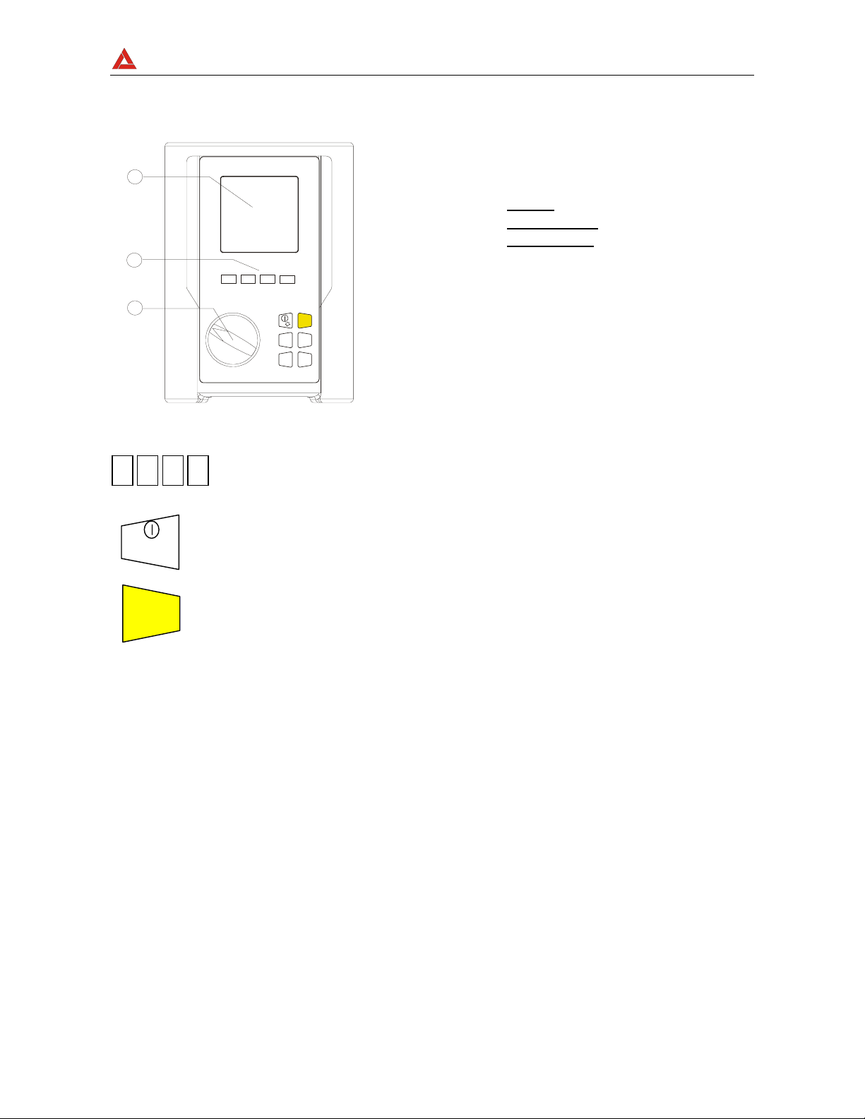
4. INSTRUMENT DESCRIPTION
LEGEND:
1
2
F1 F3F4F2
1.
Display
Function Keys
2.
3.
Rotary swit ch
F1
ON
START
3
F2 F4 F3
/
OFF
STOP
START
STOP
HOLD
SAVE
ENT ER
MENU ESC
Front panel of the Instrument
Multifunction Keys.
ON/OFF and backlight key. Press it for few seconds to switch OFF the
instrument, press it briefly to activate the backlight function.
This key starts (and stops) the measurements.
Page 16

AMPROBE
MULTITEST2000
This key saves the result displayed.
SAVE
HOLD
ENTER
This key has 2 functions: it is the confirmation key inside the
configuration menu and it freezes the displayed results using the
ANALYZER function.
MENU
This key opens the General Configuration Menu.
ESC
This key cancels modification in the configuration menus or the selected
working modes.
Page 17
AMPROBE
MULTITEST2000
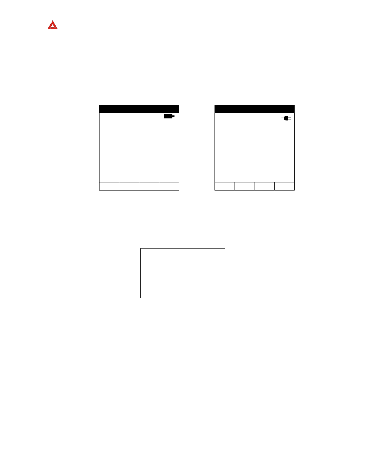
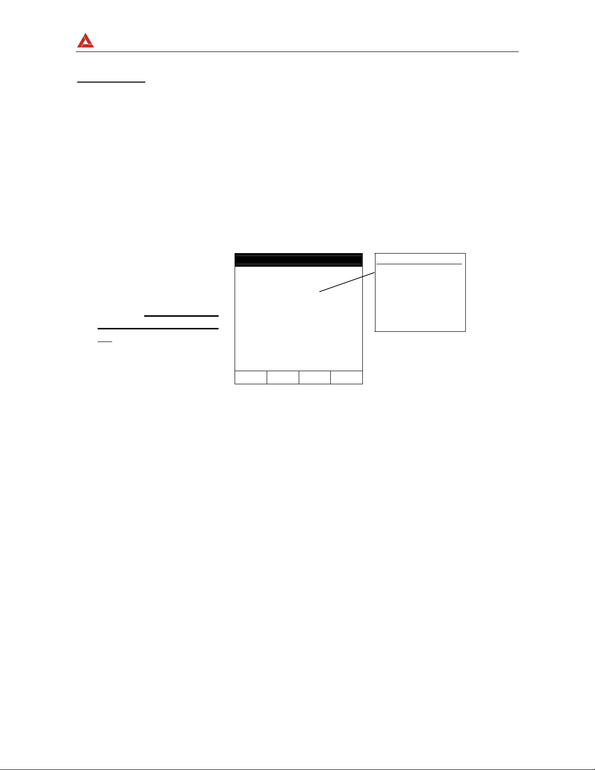
4.1. DISPLAY DESCRIPTION
The display is a graphic module with a resolution of128 x 128 pixels
The first line of the display shows date and time. If not correct, you can set the exact ones
according to the procedure described at paragraph 5.2.
On the top right corner of the display you can always see the battery indicator and, if the
external power supply adapter (optional code A0050) is connected, the corresponding
symbol.
LOWΩ 05.06.01
----Ω
R+ R-
----Ω ----Ω
---mA ---mA
AUTO 0.11Ω
FUNC CAL
27.09.00 17:35:12
SINGLE PHASE
V1 = 230.2 V
Vpk1 = 325.5 V
ThdV = 0.0 %
freq = 50.0 Hz
HARM WAVE
VOLTAGE
These symbols will be omitted in the following illustrations.
4.2. INITIAL SCREEN
When turning on the instrument by pressing ON/OFF, this screen will appear for a few
seconds:
MT 2000
AMPROBE
SN:00000000 V: X.XX
Page 18

AMPROBE
MULTITEST2000
BAUD RATE 57600
Here you can see:
• Serial number of the instrument (SN.:)
• Firmware software release (V.X.XX:)
• Transmission speed through serial RS232 (Baud Rate)
4.3. BACKLIGHT FUNCTION
When the instrument is turned on, pressing, briefly, the ON/OFF button, the backlight will
be enabled. The light will be automatically turned off after 5 seconds.
If the batteries are too low the instrument will automatically disable the backlight function.
Page 19
AMPROBE
MULTITEST2000
5. INITIAL SETTINGS
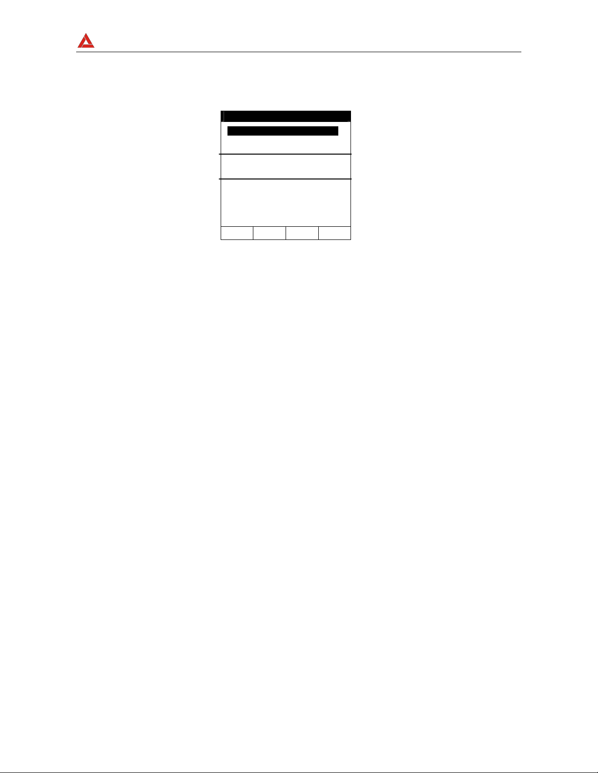
By pressing the MENU key the following screen will be displayed:
It’s not possible to enter the MENU during a recording or a Real Time Energy
measurement. Pressing this button during a recording will display the main recording
parameters (see paragraph 10.2).
5.1. HOW TO ADJUST THE CONTRAST
By pressing the multifunction keys F1 and F2, position the cursor on the CONTRAST item
and then press the ENTER key.
By pressing the multifunction keys F3 and F4, adjust the contrast (higher values
correspond to a higher contrast while lower values correspond to a lower contrast) and
press the ENTER key to SAVE the change or press ESC to quit the modification.
This setting will remain unchanged after turning off the instrument.
5.2. HOW TO SET DATE AND TIME
By pressing the multifuncti on keys F1 and F2, position the cursor on the DATE&TIME item
and then press the ENTER key.
The time is expressed as hh:mm (2 digit for hours, 2 digit for minutes) military time.
Press the ENTER key to SAVE the change or press ESC to quit the modification.
This setting will remain unchanged after turning off the instrument.
MENU GENERAL
SAFETY TEST MEMORY
ANALYZER MEMORY
RESET
ANALYZER CONFIG
RECORDER CONFIG
CONTRAST
DATE&TIME
LANGUAGE
COUNTRY
↓ ↑
Page 20

AMPROBE
MULTITEST2000
5.3. HOW TO SET THE LANGUAGE
By pressing the multifunction keys F1 and F2, position the cursor on the LANGUAGE (EN)
or LINGUA (IT) item and confirm it by pressing the ENTER key.
By pressing the multifunction keys F1 and F2, position the cursor on the desired language
and press the ENTER key to SAVE the change or press ESC to cancel the modification.
This setting will remain unchanged after turning off the instrument.
5.4. HOW TO ADJUST THE COUNTRY
By pressing the multifunction keys F1 and F2, position the cursor on the COUNTRY item
and confirm it by pressing the ENTER key. By pressing the multifunction keys F1 and F1,
select the Country among the following possibilities:
UE_m: European Countries: Distance setting in "meter" for Resistivity measurement
US_m: United States: Distance setting in "meter" for Resistivity measurement
US_ft: United States: Distance setting in "feet" for Resistivity measurement
Press the ENTER key to SAVE the change or press ESC to quit the modification.
This setting will remain unchanged after turning off the instrument.
Page 21

AMPROBE
MULTITEST2000
5.5. RESET
This option re-establishes the default settings of the instrument.
The default settings of the instrument consist of:
ANALYZER CONFIG:
Full scale of the clamps: 1000A
Transformer ratio: 1
Type of electrical equipment: 4 wires
Password: enabled
RECORDER CONFIG:
Start: Manual (the recording is started
at 00 sec mark on clock after pressing
the START/STOP key)
Stop: Manual
Integration period: 15min
Recording o f harmonics: ON
Recording of Voltage anomalies (Sag and Surge: ON
Voltage Reference for Sag and Surge detection: 230V
Upper Limit for Sag and Surge detection: 6%
Lower Limit for Sag and Surge detection: 10%
Selected vo ltages: V1
Selected voltage harmonics: THD, 01, 03, 05, 07
Selected currents: I1
Selected current harmonics: THD, 01 , 03, 05, 07
CO-GENERATION: OFF
Powers, Pf and c osϕ selected: P1
Q1i
Q1c
S1
Pf1
dpf1
Energies: Ea1
Eri1
Erc1
Page 22

AMPROBE
MULTITEST2000
The RESET command will not erase the instrument’s memory.
Page 23
AMPROBE
MULTITEST2000
6. SAFETY TEST FUNCTION S
6.1. LOWΩ: CONTINUITY TEST WITH 200mA TEST CURRENT
The measurement is taken according to EN 61557-2 and VDE 0413 part 4.
ν
WARNING:
Turn the rotary knob to the LOWΩ position.
This key allows the operator to select one of the following measuring modes:
AUTO mode (the instrument carries out two measurements with reversed
polarity and displays their average value). This mode is recommended
for the continuity test.
RT+ mode (measurement with positive polarity and the ability to set the
duration time of the test). In this case the operator can set a measuring
time long enough to permit them to move the protective conductors while
the instrument is carrying out the test so as to detect any bad
connections.
RT- mode (measurement with negative polarity and the ability to set th e
duration time of the test). In this case the operator can set a measuring
time long enough to permit him to move the protective conductors while
the instrument is carrying out the test so as to detect any bad connection.
This key permits the operator to perform a calibration (compensation for the
resistance of the cables used for the measurement).
Before carrying out the continuity test be sure that there is no
voltage at the ends of the conductor under test.
N.B.
If the resistance is lower than 5Ω (including the resistance of the calibration) the
continuity test is executed by the instrument with a test current higher than 200mA.
Page 24

AMPROBE
MULTITEST2000
If the resistance is higher than 5Ω the continuity test is executed by the instrument
with a current lower than 200mA.
We recommend that you check the calibration of the test leads before executing a
measurement according to next paragraph.
Page 25
AMPROBE
MULTITEST2000
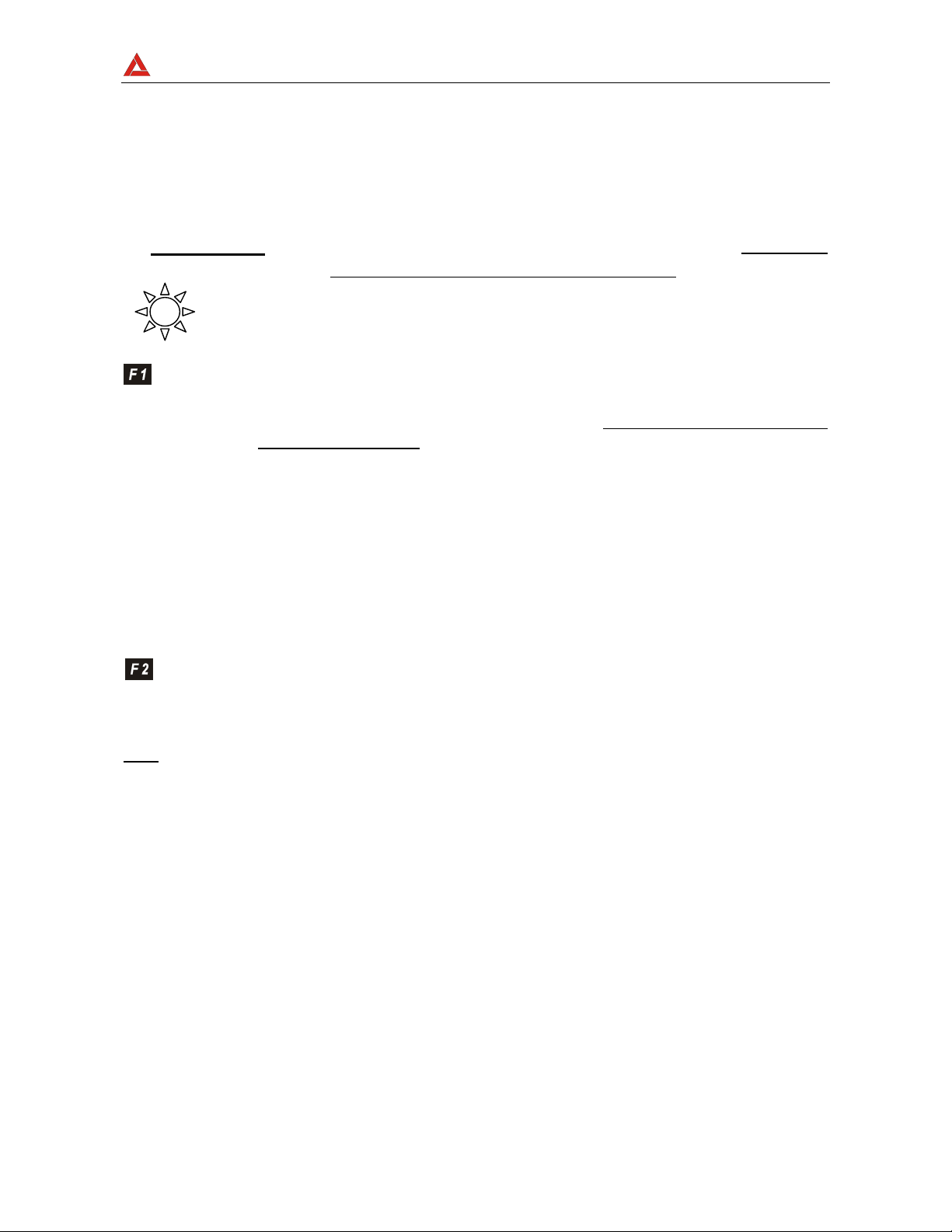
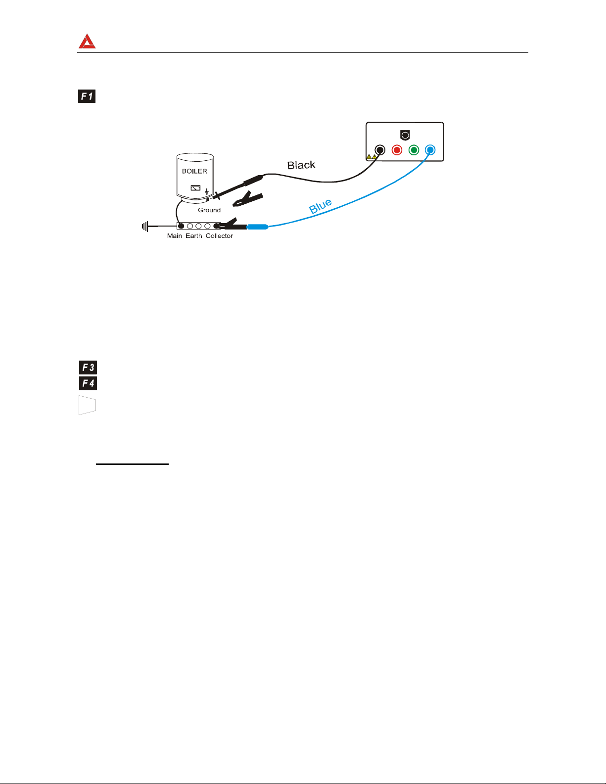
6.1.1. Calibrating the test leads ("CAL" Mode)
1. Connect the black and blue test leads to B1 and B4 input terminals
respectively.
B2 B3
B4B1
Connection of instrument terminals during calibration procedure.
2. If the test leads supplied with the instrument are not long enough for the
measurement yo u can ex tend t he blue ca ble.
3. Short-ci r c u i t the measuring cable ends making sure that the condu ctive parts of the
alligator clips make good contact with each other (see previous picture).
4. Press th e F2 key. The instrument performs the calibration.
ν
ATTENTION:
Never disconnect the test leads when the message
"MEASURING" is displayed.
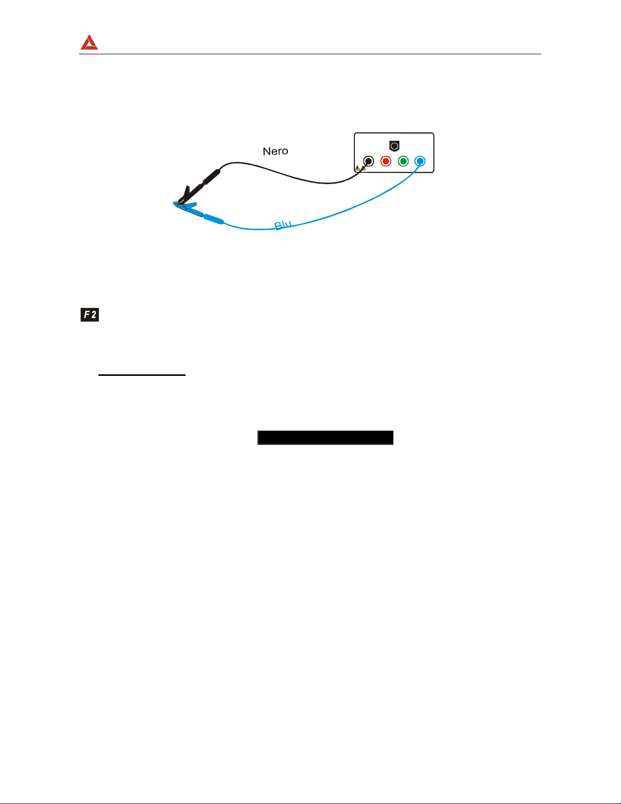
LOWΩ 05.06.01
Page 26
AMPROBE
MULTITEST2000
----Ω
R+ R-
----Ω ----Ω
---mA ---mA
AUTO 0.11Ω
FUNC CAL
A numerical value
in this field means
that the instrument
has been
calibrated; this
value remains on
the display for
any further
measurement
even though the
unit is switched off
and on again.
5. At the end of the test the result is stored and used as OFFSET (that is to say
that it is subtracted from any continuity test carried out) for all the
subsequent measurements.
Note
: The instrument performs the calibration only if the resistance of the test leads is
lower than 5Ω.
Page 27
AMPROBE
MULTITEST2000
TEST LEADS Before each measurement always assure that the
calibration is for the cables in use. During a
continuity test, if the resistance value free of
calibration (that is the resistance value less the
calibration offset value) is negative, the symbolν
is displayed. Probably the calibration resistance
value stored in the instrument memory is not for
the cables in use, therefore a new calibration must
be performed.
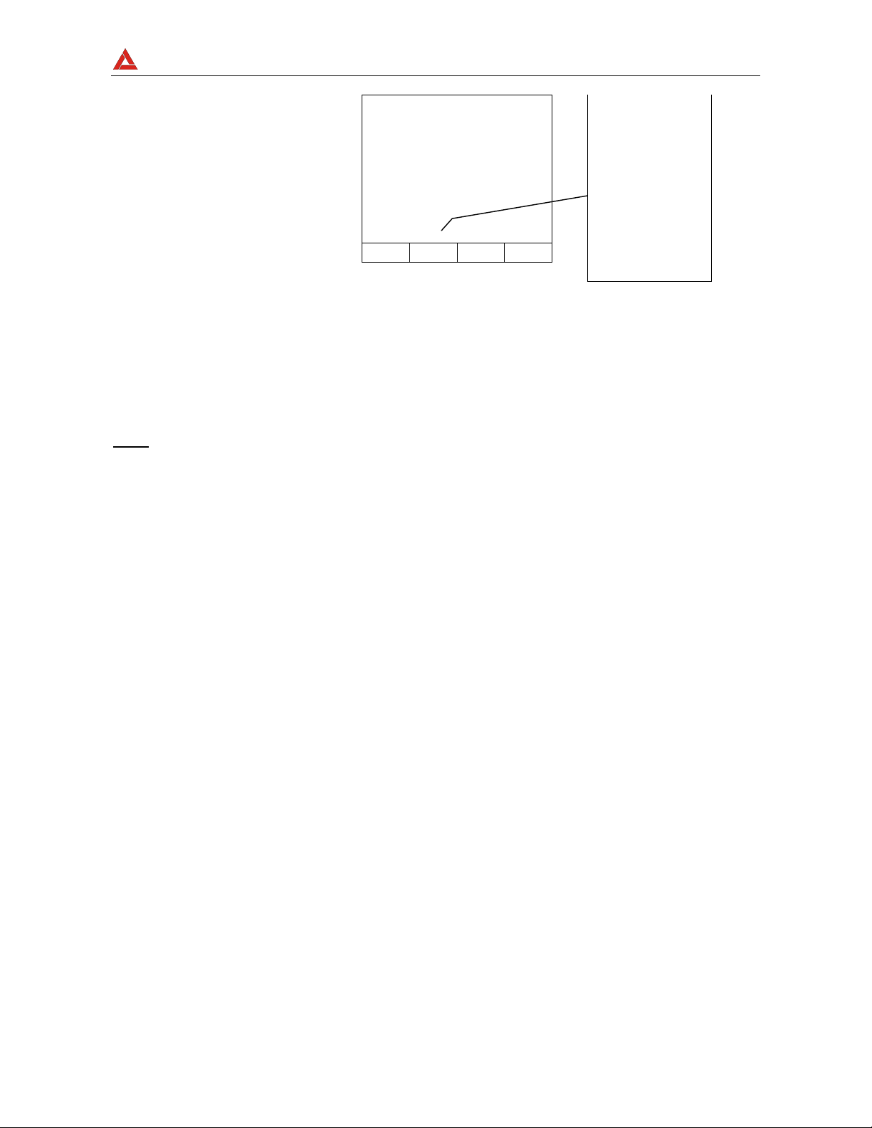
6.1.1.1. Procedure to reset test leads calibration parameters
To cancel calibration
parameters it is
necessary to perform a
calibration procedure
with a resistance of
test leads higher than
5Ω (for example with
open test leads). When
a cancellation is effected
the screen to the right
is displayed temporarily.
LOWΩ 05.06.01
ν
>
99.9
R+ R-
----Ω ----Ω
---mA ---mA
AUTO 0.11Ω
FUNC CAL
Ω
Message >99.9Ω:
means that the
instrument detected a
resistance higher
than 5Ω therefore it
will proceed with
Reset proced ure.
Page 28
AMPROBE
MULTITEST2000
6.1.2. Measurement Procedure
1. Select the desired mode using the F1 key.
2. Connect the black and blue test leads to B1 and B4 input terminals respectively
START
STOP
B2 B3
B4B1
Connection of the test leads during LOWΩ test.
3. If the cables su ppli e d with the instrument are not long enough for the measurement
you can extend the blue cable.
4. Short-circuit the test leads making sure that the conductive parts of the alligator clips
make a good contact to each other. Press the START key. If the display doesn't
show 0.00Ω repeat the test leads calibration (see paragraph 6.1.1).
5. Connect the instrument terminals to the ends of the conductor under test (see
previous picture).
6. If the mode "RT+" or "RT-" was selected use the F3, F4 keys to set the
duration of the test.
7. Press the START key. The instrument will execute the measurement. In RT+/RT-
(Timer mode) you can press START key again if you want to stop the test before the
duration set is expir ed.
ν
WARNING:
Never disconnect the test leads when the message
"Measuring" is displayed.
Page 29
AMPROBE
A
MULTITEST2000
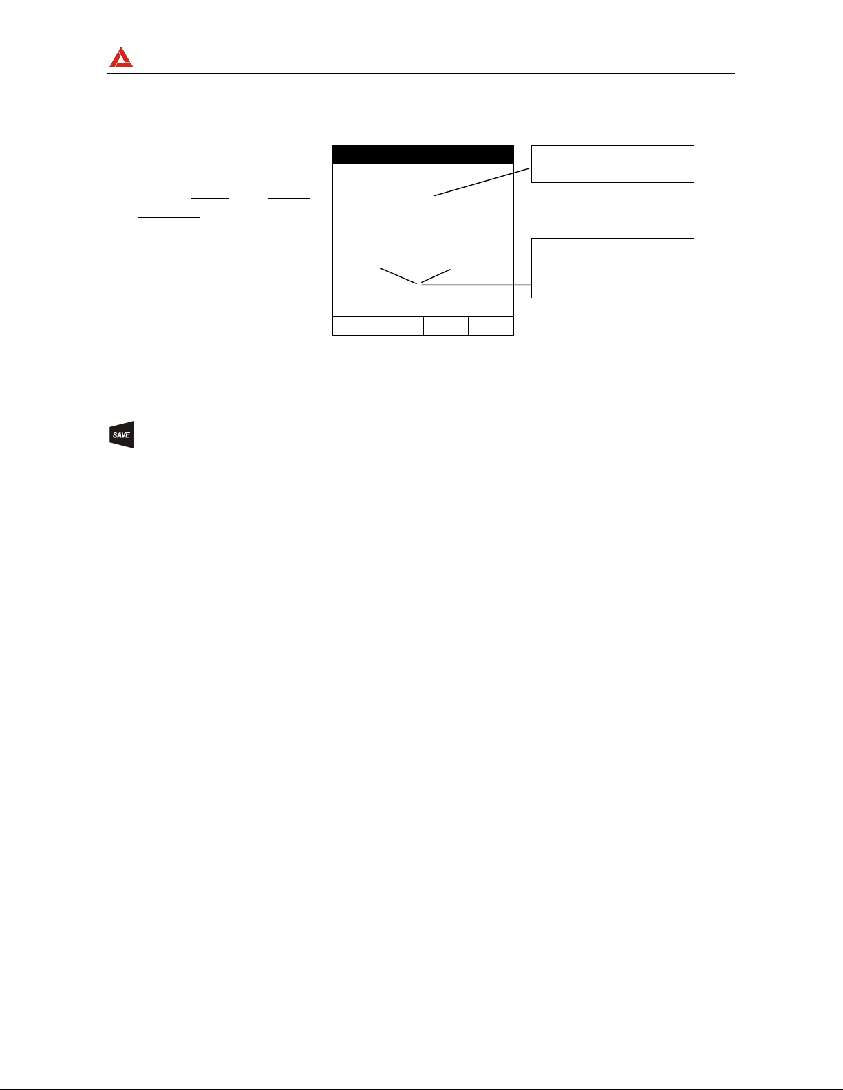
6.1.3. Results of "AUTO" mode
t the end of the test, if
the average resistance
value Ravg
than 5Ω the instrument
emits a double sound
signal indicating the
positive outcome of
the test and displays a
screen similar to the
screen to the right.
is lower
LOWΩ 05.06.01
1.05Ω
R+ R-
1.07Ω 1.03Ω
219mA 219mA
AUTO 0.11Ω
FUNC CAL
Average resistance value
(Ravg)
Resistance values and
corresponding test currents
obtained after exchanging
the polarities of test leads
The displayed result can be stored by pressing the SAVE key twice (refer to
paragraph 9.1).
Page 30
AMPROBE
MULTITEST2000
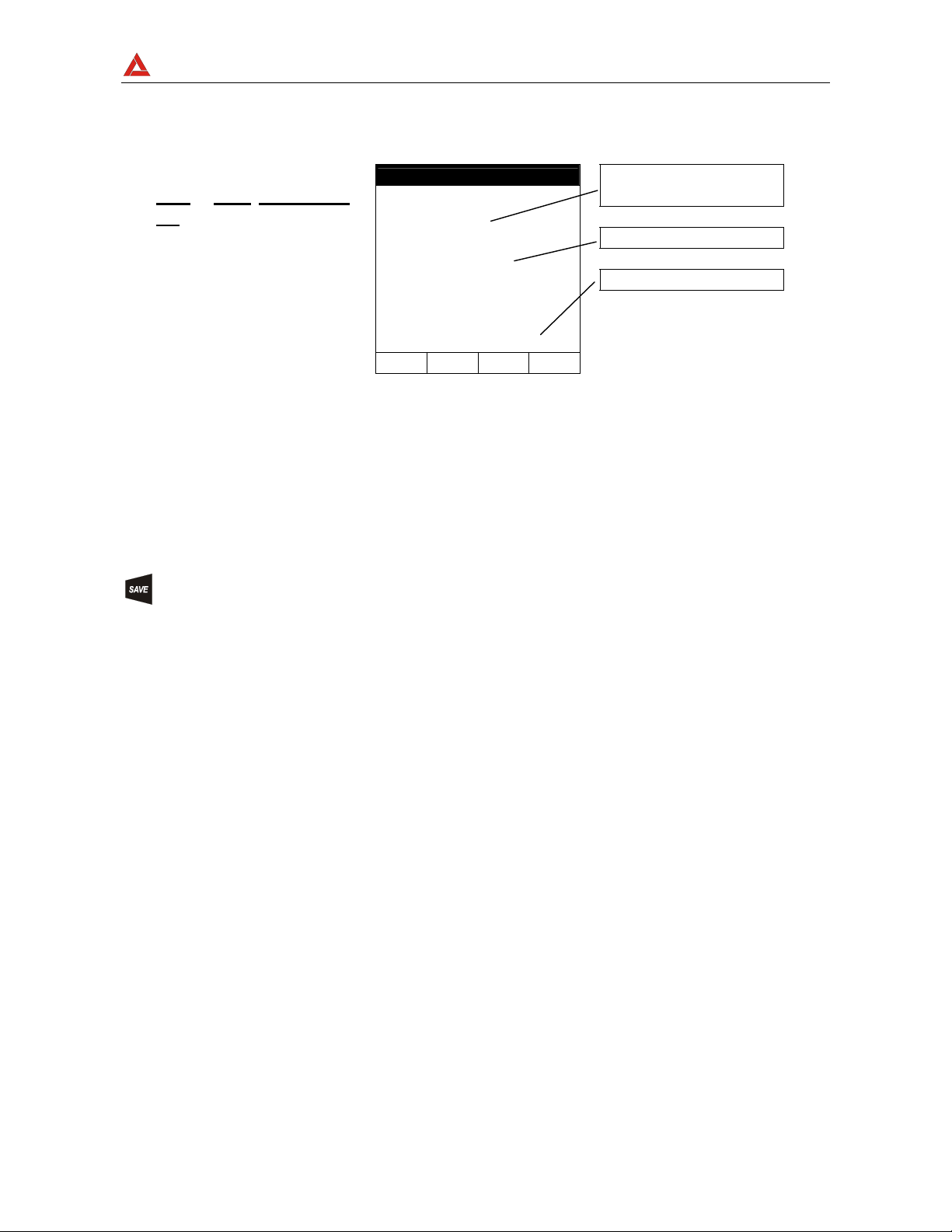
6.1.4. Results of "RT+" and "RT-" modes
If a resistance value
or RT- lower than
RT+
5Ω is detected, the
instrument emits a
double sound signal
indicating the positive
outcome of the test
displays a screen similar
to the screen to the
right.
LOWΩ 05.06.01
1.07Ω
219mA
RT+ 0.11Ω TIME: 10s
FUNC CAL
↑ ↓
Max Resistance value of
R+ or R-.
Test current
Duration of the Test
Note: We recommend the use of alligator clips and to assure the alligator clips make good
contact with the conductor under test. Indeed , in this test the instrument gives as a
final result the maximum measured value of R+ or R- and using test leads instead of
alligator clips could give you faulty results due to faulty contact between the test leads
and conductor under test
The displayed result can be stored by pressing the SAVE key twice (refer to
paragraph 9.1).
Page 31

AMPROBE
MULTITEST2000
6.1.5. "AUTO", RT+", "RT-" faulty cases
If the instrument detect
the External Power
supply adapter
connected to instrument
will show the message
displayed to the right.
LOWΩ 05.06.01
-.- -Ω
R+ R-
---Ω ---Ω
---mA ---mA
ν REMOVE POWER
AUTO 0.11Ω
FUNC CAL
Disconnect the External
Power Supply Adapter
If the terminal voltage is
higher than 15V, the
instrument does not
perform the test and
displays the screen to
the right for 5 seconds.
LOWΩ 05.06.01
R+ R-
-.--Ω -.--Ω
---mA ---mA
AUTO 0.11Ω
FUNC CAL
-.- -Ω
ν VOLT IN INPUT
ATTENTION: the test was
not performed because of
voltage at the terminal
ends.
Page 32

AMPROBE
MULTITEST2000
In the case that:
R
CALIBRATION>RMEASURED
the instrument displays
the screen to the right.
LOWΩ 05.06.01
ν 0.00Ω
R+ R-
0.00Ω 0.00Ω
219mA 219mA
CAL > RES
AUTO 0.11Ω
FUNC CAL
ATTENTION:
R
CALIBRATION >RMEASURED
THE PREVIOUS RESULTS CAN'T BE SAVED
.
If the value of
Resistance is higher
than 5Ω (but lower than
99.9Ω) the instrument
emits a long beep and
displays a screen similar
to the screen to the right
LOWΩ 05.06.01
ν 5.17Ω
R+ R-
5.17Ω 5.17Ω
209mA 209mA
AUTO 0.11Ω
FUNC CAL
Resistance value higher
than 5Ω
Test current
The displayed result can be stored pressing the SAVE key twice (refer to
paragraph 9.1).
Page 33

AMPROBE
MULTITEST2000
If the value of
Resistance is higher
than 99.9Ω the
instrument emits a long
beep and displays the
screen to the right.
LOWΩ 05.06.01
ν> 99.9Ω
R+ R-
-.--Ω -.--Ω
---mA ---mA
AUTO 0.11Ω
FUNC CAL
Resistance value higher
than 99.9Ω
ATTENTION: Value of
Resistance Out of Range
The displayed result can be stored pressing the SAVE key twice (refer to
paragraph 9.1).
Page 34

AMPROBE
6.2. MΩ: INSULATION RESISTANCE MEASUREMENT WITH 50V, 100V, 250V,
The measurements comply with IEC 61557-2 and VDE 0413 part 1.
ν
ATTENTION:
Turn the rotary knob to the MΩ position.
The F1 key allows the operator to select one of the following measuring
modes:
MAN mode (Manual mode) Recommended test.
TMR mode (Timer mode: test duration depends on the selected interval
6.2.1. Measurement Procedure
1. Select the desired mode using the F1 key.
2. Connect the test leads to the instrument input terminals B1 and B4 respectively,
MULTITEST2000
500V, 1000V TEST VOLTAGE
Before performing an insulation test make sure that the circuit
under test is not energised and all the loads are disconnected.
from 10 to 999 seconds). This test can be executed when the test
required a defined duration.
Page 35

AMPROBE
MULTITEST2000
M
I1
B2
B4B1
B3
Example: insulation measurement between phase and
earth in an electrical installation using untied cables.
3. If the cables supplied with the instrument are not long enough for the measurement
you can extend the blue cable.
4. Connect the instrument terminals to the object that is to be submitted to the
insulation test after de-energizing the circuit under test and all the relative
loads (see previous picture).
5. B y means o f F2 select the test voltage suitable for the type of test to be
performed (see Table1). The values to be selected are:
• 50V (test on telecommunication system)
• 100V
• 250V
• 500V
• 1000V
Page 36

AMPROBE
MULTITEST2000
Standard Br ief descr iption Test voltage Maximum limit value
> 0.250MΩ
> 0.500MΩ
> 1.0MΩ
> 50kΩ (se V<500V)
> 100kΩ (se V>500V)
> 230kΩ
> 1MΩ
CEI 64-8/6
CEI 64-8/4
Floor and wall insulation in civil installations
Floor and wall insulation in systems over 500V
Systems SELV or PELV
Systems up to 500V (Civil installations)
Systems over 500V
250VDC
500VDC
1000VDC
500VDC
1000VDC
EN60439 Electrical panel boards 230/400V 500VDC
EN60204 Electrical equipment of machines 500VDC
CEI 64-4 Floor insulation in medical rooms 500VDC
<1MΩ (if the floor is at least 1 year old)
<100MΩ (if the floor is at least 1year o ld)
Table1: Table reporting the test voltage and the corresponding limit values for
few Guidelines.
Rated voltage selected
for the test
50VDC
100VDC
250VDC
500VDC
1000VDC
R
= Maximum resistance
MAX
value
99.9MΩ
199.9MΩ
499MΩ
999MΩ
1999MΩ
Table2: Table of maximum resistance values which can be measured under MΩ
mode depending on the rated voltage selected.
6. If the "TMR" mode was selected use the F3, F4 keys to set the duration time of
the test:
Page 37

AMPROBE
MULTITEST2000
ν
ATTENTION:
Never disconnect the test leads from the circuit under test when
the message "MEASURING" is being displayed, as the circuit
under test may remain charged at a dangerous voltage. The
instrument has an internal "safety resistor" which is connect to
output terminal before the end of the test in order to discharge
the parasite capacities of the installation.
START
STOP
7. Press the START key.
The instrument will start the test.
MAN Mode: The test will take 4 seconds (maximum). If you keep
the START key pressed longer than 4 seconds the test
continues until the key is released.
TMR mode: The test will take the time set. If you want to stop
the test when it's running, press the START/STOP key again.
Page 38

AMPROBE
A
MULTITEST2000
6.2.2. Results of "MAN" mode
t the end of the test if
the insulation
resistance is lower
than R
and the instrument
generates the
Nominal test Voltage,
the instrument emits a
double beep,
indicating the positive
outcome of the test
(see Table2)
MAX
MΩ 05.06.01
1.07
514V 15s
MAN 500V
FUNC VNOM
MΩ
Insulation Resistance
Voltage during the Test
Duration of the Test
Test mode
Test voltage set
and displays a screen
similar to the screen to
the right.
In order to evaluate the test you must compare the result with the limits indicated in the
Guidelines (see Table1).
The displayed result can be stored pressing the SAVE key twice (according to
paragraph 9.1).
If the Insulation
resistance is higher
than R
the instrument emits a
double beep at the end
(see Table2),
MAX
MΩ 05.06.01
> 999
M
Ω
Maximum resistance value
which can be measured
(999Ω is displayed if a
rated voltage of 500V was
selected, see Table2).
Page 39

AMPROBE
of the test indicating
the positive outcome
of the test and displays
one screen similar to the
screen to the right.
MULTITEST2000
523V 15s
MAN 500V
The symbol ">" means that
the resistance value is
higher than R
MAX
.
FUNC VNOM
Test duration
The displayed result can be stored by pressing the SAVE key twice (refer to
paragraph 9.1).
Page 40

AMPROBE
MULTITEST2000
6.2.3. Results of "TMR" mode
At the end of the test if
the Insulation
resistance is lower
than R
and the instrument
generated the
Nominal test Voltage,
the instrument emits a
(see Table2)
MAX
double beep
indicating the positive
outcome of the test
MΩ 05.06.01
1.07
514V 15s
TMR 500V TIME:60s
FUNC VNOM
M
Ω
↓
Insulation Resistance
Voltage during the Test
Duration of the Test
Test mode
and displays a screen
similar to the screen to
the right.
The displayed result can be stored by pressing the SAVE key twice (according to
paragraph 9.1).
If the Insulation
resistance is higher
than R
the instrument emits a
double beep at the end
of the test indicating
(see Table2),
MAX
MΩ 05.06.01
> 999
M
Ω
Maximum resistance value
that can be measured
(999Ω is displayed if a
rated voltage of 500V was
selected, see Table2).
The symbol ">" means that
Page 41

AMPROBE
MULTITEST2000
the positive outcome
of the test and displays
a screen similar to the
screen to the right.
523V 15s
TMR 500V TIME:60s
the resistance value is
.
higher than R
MAX
FUNC VNOM
↑ ↓
Test duration
The displayed result can be stored pressing the SAVE key twice (according to
paragraph 9.1).
Page 42

AMPROBE
MULTITEST2000
6.2.4. "MAN" and "TIM ER" mode faulty cases
If the instrument
detects the External
Power supply adapter
the instrument will
show the message
displayed to the right.
MΩ 05.06.01
-.- -
---V 15s
ν REMOVE POWER
MAN 500V
FUNC VNOM
M
Ω
Disconnect the External
Power Supply Adapter
If the instrument
detects a Voltage
between the input
terminals higher than
15V, the instrument
does not perform the
test and displays the
screen to the right for
5 seconds.
MΩ 05.06.01
-.- -
---V 15s
ν VOLT IN INPUT
MAN 500V
FUNC VNOM
M
Ω
ATTENTION: the test can't be
executed. Check that the circuit is
not energized.
This result can't be saved
Page 43

AMPROBE
MULTITEST2000
If the instrument can't
generate the Nominal
Test Voltage it will
emit a long beep and
displays a screen
similar to the screen
to the right.
MΩ 05.06.01
ν 1.17 MΩ
107V 15s
MAN 500V
FUNC VNOM
Insulation Resistance
ATTENTION: the test of
resistance R
voltage value lower than the
set rated voltage. Low
insulation case. This case
occurs under low insulation
conditions or in the presence of
capacitance on the installation.
ISO
Test Duration
was taken at a
The displayed result can be stored by pressing the SAVE key twice (refer to
paragraph 9.1).
6.3.
: PHASE SEQUENCE INDICATOR
Turn the rotary knob to the
position.
6.3.1. Measurement procedure and results of "
" mode
1. Connect the Black, Red and Green connectors of the split cables to their
corresponding input terminals of the instrument B1, B2, B3.
Page 44

AMPROBE
A
MULTITEST2000
1
3
I1
B2 B3
B1
B4
Instrument connection for Phase Sequence Detection in a 400V three-phase system
2. Press the START key to execute a test.
t the end of the test
the instrument emits a
double beep
indicating that the test
has correctly
terminated and
displays the values to
the right.
LOOP 05.06.01
123
FRQ=60.0HZ V1-2=115V
V2-3=113V V3-1=114V
OK
Phase Sequence OK
Value of the Phase to Phase
Voltage
Page 45

AMPROBE
MULTITEST2000
Working mode
This result ca n be stored pressing the SAVE key twice (refer to paragraph 9.1).
Page 46

AMPROBE
MULTITEST2000
6.3.2. LOOP Faulty Cases
In the "
Phase-to-Phase voltage
is lower than 100V, the
instrument displays the
screen to the right.
" mode, if a
LOOP 05.06.01
- - -
FRQ =60.0HZ V1-2=111V
V2-3= 0 V V3-1= 0V
ν LOW VOLTAGE T
PHASE ROTATION
Phase "T2 Voltage is lower
than 100V
In the "
instrument detects two
phases connected
together it displays the
screen to the right.
" mode, if the
LOOP 05.06.01
- - -
FRQ =60.0HZ V1-2=107V
V2-3= 0 V V3-1=107V
ν PHASE DOUBLED
PHASE ROTATION
Two phases are connected
together.
THE PREVIOUS RESULTS CANNOT BE SAVED
.
Page 47

AMPROBE
MULTITEST2000
In the
voltage of one or more
phase is too low, one or
more phases has a low
voltage the instrument
will show a screen
similar to the along side
displayed.
mode, if the
LOOP 05.06.01
123
FRQ =60.0HZ V1-2=391V
V2-3= 0V V3-1= 0V
NOT CORRECT
Phase Sequence not
correct
Message “LOW Voltage
Phase T”: means that
Phase T has a low voltage
value. Similar message for
Phase R and S.
This result can be stored pressing the SAVE key twice (refer to paragraph 9.1).
Page 48

AMPROBE
6.4. EARTH: SOIL RESISTANCE AND RESISTIVITY MEASUREMENTS
Turn the rotary knob to the EARTH
The F1 key permits to select one of the following measuring modes (which
can be shown cyclically when pressing the key):
Mode "2-W" (the instrument measures the resistance between 2 points).
Mode "3-W" (the instrument measures the resistance using two auxiliary
Mode "ρ" (the instrument measures the ground resistivity).
ν
ATTENTION:
MULTITEST2000
position.
earth rods).
Never disconnect the test leads from the circuit under test when
the message "MEASURING" is displayed
Page 49

AMPROBE
MULTITEST2000
6.4.1. Measurement procedure and results of "2-W"and "3-W" mode
1. Select "2-W" or "3-W" Earth measurement mode by means of the F1 key.
2. Connect the Black, Red, Green and Blue cables to the corresponding input terminals
of the instrume nt B1, B2, B3, B4 (see possible connections in the following pictures).
1
3
N
I1
B4
B2 B3
B1
Connection for 3 point Earth resistance
measurement
I1
B2 B3
B1
1
3
N
I1
B2
B4B1
B3
1
3
N
Transf
Connection for 2 point Earth Resistance
measurement
1
3
N
B4
Connection for measuring the resistance between an extraneous conductive part and the earth system
Page 50

AMPROBE
MULTITEST2000
START
STOP
3. Press the START key. The instrument starts the test.
Page 51

AMPROBE
A
MULTITEST2000
t the end of the test
the instrument emits a
double beep indicating
that the test is
correctly terminated
and displays the values
to the right.
"3 Point" Working mode
EARTH 05.06.01
0.77
Test:04
RAVG=0.74Ω
3-W
FUNC CLR
Vd= 1V
Ω
Earth Resistance value
expressed in Ω.
Voltage value of electrical
noise
Number of Test
Average Value of Earth
Resistance calculated over
the Number of Test
displayed.
4. The instrument will show automatically the average value of the Earth resistance
calculate over the tests performed. Press F2 to RESET this value and the number of
Test.
This result can be stored by pressing the SAVE key twice (refer to paragraph 9.1).
Page 52

AMPROBE
A
MULTITEST2000
6.4.2. Measurement procedure and results of "ρ" mode
1. Select
ρ
measurement mode by means of the F1 key.
2. Select the distance d between the earth rods by means the F3 and F4 keys.
The Distance meas uri ng unit c omply with Cou ntry s ettin g (see par . 5.4).
3. Connect the 4 Bl ack, Red, Green and Blue connectors of the single cables in the
corresponding input terminals of the instrument B1, B2, B3, B4.
I1
B2 B3
B1
B4
ddd
d
Instrument connection for Earth resistivity measurement
START
STOP
4. Press the START key. The instrument starts the test.
t the end of the test
the instrument emits a
double beep
indicating that the
test is correctly
terminated and
EARTH 05.06.01
1.77
Vd= 1V
Ωm
Earth Resistivity value
expressed in Ωm.
Voltage value of electrical
noise
Page 53

AMPROBE
displays the values to
the right.
"ρ" Working mode
MULTITEST2000
Test:04
ρAVG=0.74Ω
ρ DIST= 2m
FUNC CLR ↑ ↓
Number of Test
Average Value of Earth
Resistivity calculated over the
Number of Test di splayed.
5. The instrument will show automatically the Average value of the Earth Resistivity
calculate over the tests performed. Press F2 to RESET this value and the number of
Test.
This result can be stored by pressing the SAVE key twice (refer to paragraph 9.1).
Page 54

AMPROBE
MULTITEST2000
6.4.3. "2-W", "3-W" and "ρ" faulty cases
If the instrumen t detects
the External Power
supply adapter
connected to instrument
will show the message
displayed to the right.
EARTH 05.06.01
- - -
Test:04
RAVG=0.74Ω
3-W
FUNC CLR
Vd= ---V
ν REMOVE POWER
Ω
Disconnect the External
Power Supply Adapter
If the Instrument detect
a voltage values higher
than 5V the instrument
will shows the screen
displayed to the right.
EARTH 05.06.01
ν - - -
Test:04
RAVG=0.74Ω
3-W
FUNC CLR
Vd= 230V
ν VOLT IN INPUT
Ω
Warning symbol: Voltage
noise in input.
Page 55

AMPROBE
The message "Rc
high" indicates that the
instrument can't
produce the minimum
current necessary for
measurement. Check
that the terminals are
correctly connected
and the Auxiliary earth
rod connected to B4
(blue conductor) has
not been inserted in a
pebbly or poorly
conductive ground. If
necessary pour some
water around the rod.
MULTITEST2000
EARTH 05.06.01
- - -
Test:04
RAVG=0.74Ω
3-W
FUNC CLR
Vd= 1V
ν Rc HIGH
Ω
Message "Rc": Check
Auxiliary Earth rods.
THE PREVIOUS RESULTS CANNOT BE SAVED
.
Page 56

AMPROBE
MULTITEST2000
If the Instrument
detects a Resistance
value higher than
1999Ω, the instrument
will show the screen to
the right.
EARTH 05.06.01
> 1999
Test:04
RAVG=0.74Ω
3-W
FUNC CLR
Vd= 1V
Ω
Message ">1999" means that
the resistance value is higher
than the maximum
measurable.
This result ca n be stored pressing the SAVE key twice (refer to paragraph 9.1).
If the Instrument
detects a Resistivity
value higher than
1999kΩm, the
instrument will show
the screen to the right.
EARTH 05.06.01
> 1999
Test:04
Vd= 1V
kΩm
Message ">1999" means that
the resistivity value is higher
than the maximum
measurable.
Page 57

AMPROBE
MULTITEST2000
ρAVG=0.74kΩm
ρ DIST=5m
FUNC CLR ↑ ↓
This result ca n be stored pressing the SAVE key twice (refer to paragraph 9.1).
Page 58

AMPROBE
MULTITEST2000
7. AUX: MEASUREMENT WITH EXTERNAL PROBES
Turn the rotary knob to the AUX position.
The F4 function key selects between the following functions:
Environmental Parameter & Leakage Current (mA, °C, °F, RH%, m/s, mV, Lux)
Sound Level Measurement
The "Environmental Parameter & Leakage Current" mode allows the following operations:
Display in real time the values coming from external probes or clamps.
Memorize the values displayed (pressing SAVE key).
Record (pressing the START key after a proper setting) an Input signal
coming from an External Probe or clamp among the possibilities
illustrated above. It will be possible to analyze the recorded data
ONLY by downloading it to a PC.
Please observe the difference between memorize and record: the former means that the
instrument stores in its’ memory only the actual values displayed while the latter means
that you want to store the course of the input signals during a recording time.
The "Sound Level Measurement" mode allows the following operations :
Display, in real time, the values coming from the external probe of sound
pressure level (Type 1).
Calculates, at the end of measurement, the Equivalent Level of noise
LeqT
Page 59

AMPROBE
MULTITEST2000
7.1. ENVIRONMENTAL PARAMETER AND LEAKAGE CURRENT: REAL TIME
MEASUREMENT
This working mode allows real time measurement and recording of Environmental
Parameters and Leakage current
1. Press this key to choose "AUX" mode input.
2. Pressing this function key will change the measuring unit of the instrument's
input. The following possibilities will be displayed circularly:
- - - (Instrument's input disabled)
mA (Leakage current)
°C (Celsius Temperature)
°F (Fahrenheit Temperature)
HR% (Relative humidity)
m/s (Air Speed)
mV (Voltage)
LUX (20) (Luminance: Full Scale 20Lux)
LUX (2k) (Luminance: Full Scale 2kLux)
LUX (20k) (Luminance: Full Scale 20kLux)
3. Connect the External probe or clamp to the I1 input.
Page 60

AMPROBE
MULTITEST2000
I3
B1
B2 B3 B4
Example of External probes connections
ν
ATTENTION:
While in the OFF position, some probe's output the Battery
voltage (approx 9V which is over the expected full scale). This
could influence the measurement of the instrument's inputs. So
NEVER connect the probes with the Selector placed in the OFF
position.
Page 61

AMPROBE
MULTITEST2000
PE (Protection Cunductor)
PHASE
NEUTRAL
SINGLE PHASE
LOAD OR
ELECTRICAL PLANT
PE (Protection Cunductor)
R
S
T
N
THREE PHASE
LOAD OR
ELECTRICAL PLANT
I1
B1
B2 B3 B4
Indirect Leakage Current measurement
in a single phase system
Indirect Leakage Current measurement
I1
B1
B2 B3 B4
in a three phase system
PHASE
NEUTRAL
PE (Protection C u nductor)
B1
I1
B2 B3 B4
SINGLE PHASE
LOAD OR
ELECTRICAL PLANT
DISCONNECT
ADDITIONAL
X
GROUNDING
Direct Leakage Current measurement in
a single phase system
R
S
T
N
PE (Protection Cunductor)
I1
B1
B2 B3 B4
THREE PHASE
LOAD OR
ELECTRICAL PLANT
DISCONNECT
ADDITIONAL
X
GROUNDING
Direct Leakage Current measurement in
a three phase system
4. The Instrument shows in real time the values present at the input.
Example of screen.
05.06.01 11:43:04
AUX
Example of Input Signal 1
Page 62

AMPROBE
MULTITEST2000
In1= 23°C
In1 PG+
5. Press this key to enable/disable the HOLD function (updating interruption of the
displayed data). When the HOLD function is enabled, the word HOLD is
displayed. This key is disabled during a recording. It's not possible to run a
recording if this function is enabled.
6. The displayed result can be stored by pressing the SAVE key twice (refer to
paragraph 9.1).
Page 63

AMPROBE
MULTITEST2000
7.2. ENVIRONMENTAL PARAMETER AND LEAKAGE CURRENT: RECORDING
Before starting a recording we recommend that you confirm that the real time values are
correct. Follow the measurement procedure described in paragraph 7.1.
In addition it's essential that the Instrument settings correspond to the accessories is use.
For this we recommend that you check the instrument's setting before executing an AUX
recording.
To this purpose please check the RECORDER CONFIG settings.
MENU: to enter in the MENU mode and change the instrument settings. It’s
not possible to enter the configuration MENU during a recording or an
energy measurement.
START/STOP: to record the selected parameters according to the instrument’s
settings (refer to chapter 10).
7.2.1. AUX Basic setting: RECORDER CONFIG
Place the rotary switch in the AUX position, press the MENU key, using the F1/F2 keys
select the RECORDER CONFIG item and press the ENTER Key.
MENU GENERAL
SAFETY TEST MEMORY
ANALYZER MEMORY
RESET
ANALYZER CONFIG
RECORDER CONFIG
CONTRAST
DATE&TIME
LANGUAGE
COUNTRY
↓ ↑
Page 64

AMPROBE
MULTITEST2000
It’s not possible to enter the MENU during a recording or a Real Time Energy
measurement.
This option allows you to check and eventually modify the recording parameters and the
selected parameters (up to a maximum of 3). The RECORDER CONFIG mode is divided
into 2 separate sub-pages:
st
1
page: This page allows you to set the START/ STOP mode (AUTO or
MANUAL), the START and STOP time (if AUTO mode is selected) and
the Integration Period value. Press ENTER to confirm the settings and
pass to the following page.
Press ESC to leave the Menu without modifying the existing parameters.
The page of the "RECORDER CONFIG" menu is as foll ows:
Page 65

AMPROBE
↑
MULTITEST2000
To Select MANUAL or AUTOMATIC
start/stop mode, place the cursor on
MANU or AUTO using the
multifunction key F1 or F2 and select
the desir e d mode using F3 or F4.
Use the multifunction keys F1, F2
to position the cursor on the
desired word and use the
multifunction keys F3 / F4 to modify
the value.
Press ENTER to confirm and
proceed inside the Menu the Menu
keeping the settings made.
Press ESC to leave the Menu
without modifying the existing
parameters.
MENU
RECORDER CONFIG
START
MANU
STOP
MANU
INT. PERIOD: 15min
↓
st
1
Page of the RECORDER
CONFIG MENU
+ -
Symbols Description Advised settings
START:MAN
The recording of all the selected parameters will start at 00
seconds after pressing START/STOP (see chapter 7).
☺
Page 66

AMPROBE
MULTITEST2000
STOP:MAN
START:AUTO
STOP:AUTO
INT. PERIOD
For eventual messages displayed see appendix 1 – MESSAGES DISPLAYED.
The recording of all the selected parameters will be interrupted
manually by pressing START/STOP (see chapter 9).
The recording of all the sel ected va lues wil l be start ed / int errupte d
at the set dates and times. In order to start the r ecording the user
will have to press START/STOP to set the instrument in Stand-by
mode until the start date and time previously set (see chapter 7).
The value of this parameter determines every how m any sec onds
the values of the select ed parameters will be memorised (se e
chapter 16.4.1). Available choices:
5sec,10sec,30sec,1min, 2min 5min, 10min, 15min, 30min, 60min.
☺
15min
☺
Page 67

AMPROBE
MULTITEST2000
7.3. SOUND LEVEL MEASUREMENT PROCEDURE
This working mode allows real time measurement of the Sound Pressure Level.
1. Press this key to access to "SOUND" mode.
2. Connect the Sound Level probe (class 1) to instrument using the original Serial
Optical cable (C2001) and the adapter.
F1 F3F4F2
START
STOP
HOLD
SAVE
ENTER
MEN U ESC
Connection between HT55 and the instrument
3. Set the switch on the Sound Level probe to ON position.
The noise probe HT55 is not equipped with the auto-power-off device, in
order to allow also long measurements. To maximize the battery duration
put the instrument ON only during the measurements.
START
STOP
4. Press START/STOP to run the measurement. The message "HT55 no RS232"
means that the instrument is not correctly connected with the noise probe HT55.
Please check:
ATTENTION
Page 68

AMPROBE
MULTITEST2000
- the Sound Level Probe batteries.
- if the Switch on the Sound Level Probe in the ON position.
- if the cable and the adapter are correctly connected.
During the
measurement the
instrument shows the
screen indicated to side.
The Peak value will be
available only at the end
of measurement.
SOUND 05.06.01
SPL 84.2dB
Peak ----dB
Duration 0000:00:00
MEASURING...
Sound Pressure Level
Measurement Duration
PG+
START
STOP
5. Press START/STOP to stop the measurement and display the message
"waiting for final SPL" and then the following screen will be displayed:
.
05.06.01 11:43:04
Leq 94.2dB
Peak 121.7dB
Duration 0000:00:00
SOUND
MEASURING...
Sound Pressure Level
Peak Value (dBA)
Measurement Duration
Page 69

AMPROBE
It contains:
- Duration: duration of the measurement expressed in hours : minutes : seconds
- L
- Peak: peak value of SPL.
: value of equivalent noise level during the measurement.
Eq
L
eq
6. The displayed result can be stored pressing the SAVE key twice (according to
paragraph 9.1).
MULTITEST2000
PG+
+ 01
⎡
1
10
⎢
0
t
⎢
⎣
log10
tt
[]
⋅=
∫
1
t
0/)(
⎤
2
⎥
dtptp
⎥
⎦
Page 70

AMPROBE
MULTITEST2000
7.3.1.1. SOUND LEVEL MEASUREMENT "faulty cases"
If the instrument
communicate with the
probe, the message
"HT55: NO RS232" will
be displayed.
SOUND 05.06.01
SPL ----dB
Peak ----dB
Duration 0000:00:00
ν
HT55:NO RS232
PG*
The instrument can't
communicate with Probe.
Check if the Batteries aren't
weak, the cable and the
adapter are correctly
connected.
THE PREVIOUS RESULTS CAN'T BE SAVED.
Page 71

AMPROBE
MULTITEST2000
8. ANALYZER
This function allows the following operat ions:
display in real time the electrical parameters of a single phase systems (with and
without neutral wire) and the harmonic analysis of voltage and current.
conduct a direct Energy measurement (without memorizing).
memorize (pressing SAVE key) the sampled values of the Parameters present at
instrument input generating a "Smp" record inside instrument memory. It will be
possible to analyse the memorized data ONLY by transferring it to a PC.
record simultaneously (pressing the START key after a proper setting): RMS values
of voltage, current, corresponding harmonics, active, reactive and apparent powers,
power factors and cosϕ, active, reactive and apparent energies, voltage anomalies
(voltage sag and surge) with 10ms resolution. It will be possible to analyse the
recorded data ONLY by transferring them to a PC.
It's fundamental the In strument settings correspond to th e Installation type under test and
accessories is use. For this we recommend you to check instrument's setting before
execute an ANALYSIS measurement.
Select the ANALYZER rotary switch position. By pressing the MENU key the following
screen will be displayed:
MENU GENERAL
SAFETY TEST MEMORY
ANALYZER MEMORY
RESET
ANALYZER CONFIG
RECORDER CONFIG
CONTRAST
DATE&TIME
LANGUAGE
COUNTRY
↓ ↑
Page 72

AMPROBE
MULTITEST2000
It’s not possible to enter the MENU during a recording or a Real Time Energy
measurement.
Generally to check instrument's settings you must check "ANALYZER CONFIG" and
"RECORDER CONFIG" items.
Page 73

AMPROBE
MULTITEST2000
8.1. BASIC SETTING: ANALYZER CONFIG
Place the rotary switch in the ANALYZER position, press the MENU key, using the F1/F2
keys select the ANALYZER CONFIG item and press the ENTER Key.
The following page will be displayed:
ANALYZER CONFIG
SYSTEM :SINGLE
FREQUENCY:50HZ
CURRENT RANGE:1000A
CLAMP TYPE: STD
TV RATIO:0001
PASSWORD:ON
↓
↑
+
-
This page of setting can be confirmed by pressing the ENTER key or cancelled by
pressing the ESC key.
8.1.1. Type of electrical system under test
The parameter SYSTEM is fixed to "SINGLE" value as Multitest 2000 is able only to
analyse Single Phase system.
8.1.2. How to set the fundamental frequency
Position the cursor on the corresponding word by pressing the multifunction keys F1 and
F2 and select the network frequency between the possible values 50Hz and 60Hz by
pressing the multifunction keys F3 and F4. This parameter is important ONLY if the input
voltage is not sufficient to recognise the value of the frequency (for example, only the
clamps for the current measurement are connected). In this case the instrument generates
an internal synchronism equal to the value of the set frequency.
Page 74

AMPROBE
MULTITEST2000
8.1.3. How to set the current range
The value of this parameter must be always equal to the full scale of the current
clamp used to take the measurement. In case multi-scale clamp is used, the value of this
parameter must be equal to the scale selected on the clamp.
Set the desired value by pressing the multifunction keys F3 and F4.
Page 75

AMPROBE
MULTITEST2000
8.1.4. How to set the Clamp Type
The value of this parameter must be always equal to the clamp type you are using.
Two types of clamps are available:
STD: for Standard clamps or Current Transformer
FLEX: for Flexible clamps.
Set the desired value by pressing the multifunction keys F3 and F4.
8.1.5. How to set the value of the transformer voltage ratio (TV RATIO)
The instrument can also be interfaced with step-down transformers in the equipment under
test: it can display the value of he voltages present on the primary winding of these
transformers. To do this it will be necessary to set the value of the transformers’ windings
ratio from 2:1 to 3000:1. The default is set at 1:1 for measurements of none transformer
systems.
Select “TV RATIO” in the ANALYZER CONFIG menu. Set the desired value by pressing
the multifunction keys F3 and F4.
8.1.6. How to enable/ d i s able the pass word
The instrument is provided with a protective routine to avoid the risk of being disturbed or
interrupted during a recording or an energy measurement. Once a recording or a direct
energy measurement has been started (with the option “PASSWORD” enabled), after
about 3 minutes from the last key pressure or switch rotation it won’t be po ssible to press
START/STOP to stop the recording, “PASSWORD” will be displayed and it will be
necessary to insert the password.
In order to insert the password (which is not changeable), press the multifunction keys in
the following sequence (within 10 seconds):
F1, F4, F3, F2
Page 76

AMPROBE
MULTITEST2000
If you wait more than about 10 seconds the display will return to the meter mode and the
instrument will continue recording. If you insert a wrong password the message “Password
error” will be displayed under “PASSWORD”. After a few second s the display will re turn to
meter mode and the instrument will continue recording. In order to enable/disable this
option the correct password will have to be entered. The display will return to meter mode
and START/STOP will have to be pressed again to stop the recording. You will then need
to re-enter the “ANALYZER CONFIG” menu and scroll up or down to the item
“PASSWORD: ON” using the multifunction keys F1 and F2. Then turn the password off by
pressing the multifunction keys F3 and F4.
Page 77

AMPROBE
MULTITEST2000
8.2. BASIC SETTING: RECORDER CONFIG
Place the rotary switch in the ANALYZER position, press the MENU key, using the F1/F2
keys select the RECORDER CONFIG item and press the ENTER Key.
This option allows you to check and eventually modify the recording parameters and the
selected parameters (up to a maximum of 62+Frequency). If the number of selected
values exceeds 63 the message "too many param" will be displayed. The RECORDER
CONFIG mode is divided into 4 separate sub-pages:
st
1
page: This page allows you to set the START/ STOP mode (AUTO or MANUAL),
the START and STOP time if AUTO mode is selected, the Integration
Period value, the Enabling/Disabling of Voltage Anomalies detection, the
Enabling/Disabling of Harmonics detection. Press ENTER to confirm the
settings and pass to the following page.
Press ESC to leave the Menu without modifying the existing parameters.
2nd page: This page is devoted to the settings relevant to the VOLTAGE recording.
Press ENTER to confirm the settings and pass to the following page.
Press ESC to leave this page without modifying the existing parameters.
From this page you can enter the sub-page “Harmonics” which permits to
select the voltage harmonics to be recorded.
Press ENTER to confirm the settings and leave the “Menu Harmonics".
Press ESC to leave the "Menu Harmonics" without modifying the existing
parameters.
3rd page: This page is devoted to the settings relevant to the CURRENT recording.
Press ENTER to confirm the settings and pass to the following page.
Press ESC to leave this page without modifying the existing parameters.
From this page you can enter the sub-page “Harmonics” which permits to
select the current harmonics to be recorded.
Press ENTER to confirm the settings and leave the “Menu Harmonics".
Press ESC to leave the "Menu Harmonics" without modifying the existing
parameters.
Page 78

AMPROBE
MULTITEST2000
4th page: Menu composed of two sub-pages devoted to the selection of the
POWERS and ENERGIES t o be recor ded. From this page you can enter
the sub-page “POWER” and “ENERGY” which permits to select the
parameters to be recorded.
Selecting the active powers for the recording, the corresponding active
energies will be automatically selected.
Selecting the reactive powers for the recording, the corresponding reactive
energies will be selected.
Press ENTER to leave this page confirming the modifications made.
Press ESC to leave the "Menu" without modifying the existing parameters.
The various pages of the "RECORDER CONFIG" can be schematised as follows:
Page 79

AMPROBE
↑
↑
MULTITEST2000
To Select MANUAL or AUTOMATIC
start/stop mode, place the cursor on
MANU or AUTO using the
multifunction key F1 or F2 and select
the desir e d mode using F3 or F4.
Use the multifunction keys F1, F2
to position the cursor on the
desired word and use the
multifunction keys F3 / F4 to modify
the value.
Press ENTER to confirm th is page
and proceed inside the Menu the
Menu keeping the settings made.
Press ESC to leave this page
without modifying the existing
parameters.
ENTER
+ -
MENU
RECORDER CONFIG
START
MANU
STOP
MANU
INT. PERIOD: 15min
HARM REC: ON
ANOM REC: ON
↓
st
1
Page of the RECORDER
CONFIG MENU
Use the multifunction keys
F1, F2 to position the cursor
on the desired symbol and
use the multifunction keys
F3 / F4 to select / deselect
the desired parameter (it’s
selected if marked in black).
Press ENTER to confir m and
leave the Menu keeping the
settings made.
Press ESC to leave this
page without modifying the
existing parameters.
RECORDER CONFIG
VOLTAGE:
V1
HARM. REC:Pg (ON)
Vref P-N: 230V
LIM+: 06% (243.8V)
LIM-: 10% (207.0V)
↓
+ -
Example of 2nd page with ANOM
flag enabled
Page 80

AMPROBE
MULTITEST2000
If you want to change Voltage Harm. Selection place the
cursor on the corresponding “Pg” symbol then Press F3
ENTER
RECORDER CONFIG
VOLTAGE HARMONICS
Thd DC 01 02 03 04
05 06 07 08 09 10 11
12 13 14 15 16 17 18
19 20 21 22 23 24 25
26 27 28 29 30 31 32
33 34 35 36 37 38 39
40 41 42 43 44 45 46
47 48 49
↓ ↑
Example of sub-page
"VOLTAGE HARMONICS"
+ -
Use the multifunction keys F1,
F2 to position the cursor on the
desired voltage harmonic and
use the multifunction keys F3 /
F4 to select / deselect (it’s
selected if highlighted in
black).
Press ENTER to confirm this
page.
Press ESC to leave the Menu
without modifying the existing
settings.
The instrument wil l record the
values of the selected
harmonics corresponding to
the voltages selected in one of
the two pages of the Menu
previously illustrated.
of RECORDER CONFIG MENU
From 2nd page
ENTER
Use the multifunction keys
F1, F2 to position the
cursor on the desired
word and use the
multifunction keys F3 / F4
to modify the value or
select / deselect the
desired parameter (it’s
selected if marked in
black).
Press ENTER to confirm.
Press ESC to leave the
Menu without modifying
the existing settings.
Page 81

AMPROBE
↑
↑
MULTITEST2000
RECORDER CONFIG
CURRENT:
I1
HARM. REC:Pg (ON)
If you want to change Current Harm. Selection place
Cursor on the corresponding “Pg” symbol then Press F3
ENTER
Thd DC 01 02 03 04
05 06 07 08 09 10 11
12 13 14 15 16 17 18
19 20 21 22 23 24 25
26 27 28 29 30 31 32
33 34 35 36 37 38 39
40 41 42 43 44 45 46
47 48 49
↓
Example of 3rd page
RECORDER CONFIG
CURRENT HARMONICS
↓
Example of sub-page
"CURRENT HARMONICS"
+ -
+ -
Use the multifunction keys F1,
F2 to position the cursor on the
desired current harmonic and
use the multifunction keys F3 /
F4 to select / deselect (it’s
selected if marked in black).
Press ENTER to confirm this
page.
Press ESC to leave this page
without modifying the existing
settings.
The instrument will record the
values of the selected harmonics
corresponding to the currents
selected in one of the two pages
of the Menu previously
illustrated.
Page 82

AMPROBE
MULTITEST2000
of RECORDER CONFIG MENU
From 3rd page
ENTER
RECORDER CONFIG
CO-GENERATION:ON
POWER:Pg
ENERGY:Pg
↓ ↑
Example of 4th page
+ -
ENTER
In order to select the POWER to be recorded use the
multifunction keys F1, F2 to position the cursor on the
corresponding “Pg” Symbol and then press F3
Page 83

AMPROBE
↑
MULTITEST2000
RECORDER CONFIG
P1 Q1i Q1c S1
Pf1 dPf1
↓
Example of POWER sub-page
+ -
Selecting the active powers for the recording, the corresponding active energies will be
automatically selected.
Selecting the reactive powers for the recording, the corresponding reactive energies will be
selected.
Page 84

AMPROBE
MULTITEST2000
of RECORDER CONFIG MENU
From 3rd page
ENTER
RECORDER CONFIG
CO-GENERATION:ON
POWER:Pg
ENERGY:Pg
↓ ↑
Example of 4th page
+ -
ENTER
In order to select the ENERGIES to be recorded use the
multifunction keys F1, F2 to position the cursor on the
corresponding “Pg” Symbol and then press F3
Page 85

AMPROBE
↑
MULTITEST2000
RECORDER CONFIG
Ea1 Eri1 Erc1 Es1
↓
Example of ENERGY sub-page
in single-phase mode
+ -
Selecting/deselecting the active energies for the recording, the corresponding active powers will
be automatically selected/deselected.
Selecting/deselecting the reactive energies for the recording, the corresponding reactive powers
will be selected/deselected
Selecting/deselecting the reactive energies for the recording, the corresponding reactive powers
will be selected/deselected.
Page 86

AMPROBE
MULTITEST2000
Symbols Description Advised settings
START:MAN
STOP:MAN
START:AUTO
STOP:AUTO
INT. PERIOD
HARM REC.
ANOM REC.
V1 Voltage RMS value
THD, DC, 01...49 Voltage Total Harmonic Distortion, DC Component, 01..49
Vref
(only if ANOM. REC flag
has been set ON)
LIM+, LIM-
(only if ANOM. REC flag
has been set ON)
The recording of all the selected parameters will start at 00
seconds after pressing START/STOP (see chapter 10.1).
The recording of all the selected parameters will be interrupted
manually by pressing START/STOP (see chapter 10.1).
The recording of all the selected values will be started / interrupted at
the set dates and times. In order to start the recording the user will
have to press START/STOP to set the instrument in Stand-by mode
until the start date and time previously set (see chapter 10.1).
The value of this parameter determines every how m any sec onds
the values of all the selected parameters will be memorised
(see chapter 16.8.1). Available choices:
5sec,10sec,30sec,1min,2min,5min,10min,15min,30min,60min.
ON = the instrument will record the values of the selected
voltage and current harmonics.
OFF = the instrument will not record any voltage or current
harmonic selected
ON = the Instrument will record Voltage Anomalies (voltage Sag
and Surge) (see paragraph 16.5)
OFF = the instrument will not record any voltage Sag and Surge
Harmonics respectively
RMS reference value for Voltage used in Voltage Anomalies
detection (Voltage Sag and Surge). The Reference is:
a) Voltage Phase to Neutral for Single Phase and 4 wires three
phase system
b) Voltage Phase to Phase for 3 wires three phase system
High and Low Voltage Percent threshold used in Voltage
Anomalies detection (Voltage Sag and Surge). These parameters
can be adjusted in range 3% ÷ 30% (step 1%).
Example: Three Phase System 4 wires.
Vref = 230, LIM+= 6%, LIM-=10% =>
High Lim = 243.8V, Low Lim = 207.0V
☺
☺
15min
☺
☺
☺
☺
V1
☺
THD,01,03,05,07
☺
Single phase: 230V
3 Phase system:
3 wires: 400V
4 wires 230V
☺
+6% / -10%
Page 87

AMPROBE
MULTITEST2000
The Instrument will detect a voltage Anomalies if the RMS
Voltage Values (calculated every 10ms) beyond the above
calculated thresholds (see paragraph 16.5.
☺
I1
☺
I1
THD, DC, 01..49 Current Total Harmonic Distortion, DC Component, 01..49
Current RMS value.
Harmonics respectively
THD,01,03,05,07
Page 88

AMPROBE
MULTITEST2000
ON = the inst rument is able to fac e situations of CO-GENE RATION
of electrical equipment (that is, the equipment under test is
able to generate energy besides absorbing it). Accordingly, the
CO-GENERATION
P1 Active Power
Q1i Inductive Reactive Power
Q1c Capacitive Reactive Power
S1 Apparent Power
Pf1 Power factor
dpft1
instrument will record the powers and energies both absorbed
and generated (see paragraph 16.7. 1). If thi s flag is enabled
the maximum number of parameters which can be
selected decrease to 38.
OFF = the instrument will record ONLY the powers and energies
absorbed.
cosϕ
☺
☺
P1
☺
Q1i Q1c
☺
S1
☺
Pf1 dPf1
☺
Ea1 Active energy
Eri1 Inductive reactive energy
Erc1 Capacitive reactive energy
The value of the network frequency is automati cally selected if the voltage is selected.
The symbols "i" and "c" stand for reactive powers (Q), power factors (Pf) and cosϕ (dpf) inductive and cap acit iv e respectively.
Selecting a power factor (Pf) or a cosϕ (dPf) for the recording automatically their inductive value and their capacitive value will be
recorded separately.
Ea1
☺
Eri1 Erc1
Page 89

AMPROBE
MULTITEST2000
For eventual messages displayed see appendix 1 – MESSAGES DISPLAYED.
Page 90

AMPROBE
MULTITEST2000
8.3. ANALYZER FUNCTIONS
For a simple usage, the main working mode of the ANALYZER mode can be
selected by means of F3 and F4.
"VOLTAGE" function: to be used to display voltage and corresponding
harmonics (see paragraph 8.4)
"CURRENT" function: to be used to display current and corresponding
harmonics (see paragraph 8.5)
"POWER" function: it permits to display all the parameters measurable by
the instrument: voltage, current, active, reactive and
apparent power, power factor, cosϕ and energy (see
paragraph 8.6)
"ENERGY" function: to be used to display active, reactive and apparent
power, power factor, cosϕ and energy (see paragraph
8.7)
More practically, we may schematise the right procedure of use the ANALYZER function
as follows:
1. Check and eventually modify the "ANALYZER CONFIG" settings of the instrument
2. Using F3 and F4, select the type of measurement to be taken
3. Connect the instrument to the electrical system to be tested
4. Evaluate the values of the parameters under test
5. If you want to record:
a) Decide what to record
b) Press MENU and check if the "RECORDER CONFIG" settings meet your
requirements
6. Connect the External Power Supply A0050 (optional)
7. Start the recording by pressing START/STOP.
Page 91

AMPROBE
MULTITEST2000
Page 92

AMPROBE
MULTITEST2000
8.4. "VOLTAGE" FUNCTION
This function permits you to display in real time the RMS value of AC/DC voltage,
the peak, the Thd value (see paragraph 16.6), the waveform and the harmonic
spectrum of the voltage.
8.4.1. Symbols
The VOLTAGE pos i tion has thre e w or king modes:
METER
WAVE
HARM
These modes will be described in detail in the next paragraphs.
The symbols used are described below:
Symbol Description
V1 Voltage RMS value
Vpk1 Peak value of the voltage
h01 ÷ h49 Harmonic 01 ÷ Harmonic 49.
ThdV Factor of total harmonic distortion of the voltage (see paragraph 16.6).
freq Network frequency
Tab. 1: Symbols used in the position VOLTAGE
Page 93

AMPROBE
MULTITEST2000
8.4.2. "METER" mode
In this mode the instrument shows the below screens according to the settings made as
per paragraph 8.1.
27.09.00 17:35:12
SINGLE PHASE
V1 = 230.2 V
Vpk1 = 325.5 V
ThdV = 0.0 %
freq = 50.0 Hz
HARM. WAVE
Example of screen
VOLTAGE
PG- PG+
The symbols used are described in Tab. 1.
For eventual messages displayed see appendix 1 – MESSAGES DISPLAYED.
Following keys are enabled:
F1: to pass to "HARMONIC" mode (see paragraph 8.4.3).
F2: to pass to "WAVE" mode (see paragraph 8.4.4).
F3/F4: to pass to previous/next function respectively.
SAVE: to save in the instrument memory a record of “Smp” type (see
paragraph 9.2) containing the instantaneous values of voltage and
current present on the instrument inputs. This function is disabled
during a recording.
Page 94

AMPROBE
MULTITEST2000
ENTER/HOLD: to enable/disable the HOLD function (updating interruption) of the
displayed data. All the previous functions remain however available.
When the HOLD function is enabled, the word HOLD is displayed.
When this function is enabled it’s not possible to record or take an
energy measurement. This function is disabled during a recording or
an energy measurement.
MENU: to enter in the MENU mode and change the instrument settings (see
paragraph 8.1 and 8.2). It’s not possible to enter the configuration
MENU during a recording or an energy measurement.
START/STOP: to record the selected parameters according to the instrument’s
settings (see chapter 10).
Page 95

AMPROBE
MULTITEST2000
8.4.3. "HARM" mode
Selecting the HARM mode the screen below will be displayed according to the settings
made as per paragraph 8.1. The screen show the harmonics (see paragraph 16.6) of the
voltage.
27.09.00 17:35:12
V1 = 230.2 V
h03 = 10.2 V
h03 = 4.3 %
ThdV = 11.0 %
h49
Example of screen
← →
The symbols used are described in Tab. 1.
For eventual messages displayed see appendix 1 – MESSAGES DISPLAYED.
The displayed histograms represent the harmonic content of the voltage under test. The
value of the first harmonic h01 (fundamental at 50Hz) is not represented in scale along
with the other harmonics in order to maximize the display of the latter. In case both voltage
and current are connected to the instrument inputs, eventual negative values of the
harmonics (therefore represented under the horizontal axis), indicate that such voltage
harmonics are “generated” by the load.
Following keys are enabled:
Page 96

AMPROBE
MULTITEST2000
F3, F4: to move the cursor of the selected harmonic leftwards and rightwards
respectively. At the same time the values relevant to the order no. of
the selected harmonic and to the corresponding absolute and relative
values (calculated on the basis of the fundamental) are updated.
F2: to display the page of the harmonics h01 ÷ h24 (symbol h24) or that
ESC: to return back to METER mode (see paragraph 8.4.2).
of the harmonics h25 ÷ h49 (symbol h49).
SAVE: to save in the instrument memory a record of “Smp” type (see
paragraph 9.2) and the instantaneous values of voltage and current
present on the instrument inputs. This function is disabled during a
recording.
ENTER/HOLD: to enable/disable the HOLD function (updating interruption) of the
displayed data. All the previous functions remain however available.
When the HOLD function is enabled, the word HOLD is displayed.
When this function is enabled it’s not possible to record or take an
energy measurement. This function is disabled during a recording or
an energy measurement.
MENU: to enter in the MENU mode and change the instrument settings (see
paragraph 8.1 and 8.2). It’s not possible to enter the configuration
MENU during a recording or an energy measurement.
START/STOP: to record selected parameters according to the instrument’s settings
(see chapter 10).
Page 97

AMPROBE
MULTITEST2000
8.4.4. "WAVE" mode
Selecting the WAVE mode the screen below will be displayed according to the settings
made as per paragraph 8.1. The screen show the waveform of the voltage.
27.09.00 17:35:12
V1 = 230.2 V
Vpk1 = 325.5 V
freq = 50.0 Hz
Example of screen
The symbols used are described in Tab. 1.
For eventual messages displayed see appendix 1 – MESSAGES DISPLAYED.
Following keys are enabled:
ESC: to return back to METER mode (see paragraph 8.4.2).
SAVE: to save in the instrument memory a record of “Smp” type (see
paragraph 9.2) containing the instantaneous values of voltage and
current present on the instrument inputs. This function is disabled
during a recording.
Page 98

AMPROBE
MULTITEST2000
ENTER/HOLD: to enable/disable the HOLD function (updating interruption) of the
displayed data. All the previous functions remain however available.
When the HOLD function is enabled, the word HOLD is displayed.
When this function is enabled it’s not possible to record or take an
energy measurement. This function is disabled during a recording or
an energy measurement.
MENU: to enter in the MENU mode and change the instrument settings (see
paragraph 8.1 and 8.2). It’s not possible to enter the configuration
MENU during a recording or an energy measurement.
START/STOP: to record selected parameters according to the instrument’s settings
(see chapter 10).
Page 99

AMPROBE
MULTITEST2000
8.5. "CURRENT" FUNCTION
This function permits to display in real time the RMS value of AC/DC current, the peak, the
Thdl value (see paragraph 16.6), the waveform and the harmonic spectrum of the current.
8.5.1. Symbols
The CURRENT position has three working modes:
METER
WAVE
HARM
These modes will be described in detail in the next paragraphs.
The symbols used are described below:
Symbol Description
I1 Current RMS value
Ipk1 Peak value of the current
h01 ÷ h49 Harmonic 01 ÷ harmonic 49.
ThdI Total harmonic distortion factor of the current (see paragraph 16.6).
freq Network frequency
Tab. 2: Symbols used in the position CURRENT
Page 100

AMPROBE
MULTITEST2000
8.5.2. “METER" mode
In this mode the instrument shows the below screens according to the settings made as
per paragraph 8.1.
27.09.00 17:35:12
SINGLE PHASE
I1 = 30.21 A
Ipk1 = 49.53 A
ThdI = 23.06 %
freq = 50.0 Hz
CLAMP TYPE: FLEX
HARM. WAVE
Example of screen
CURRENT
PG- PG+
The symbols used are described in Tab. 2.
For eventual messages displayed see appendix 1 – MESSAGES DISPLAYED.
Following keys are enabled:
F1: to pass to "HARMONIC" mode (see paragraph 8.5.3).
F2: to pass to "WAVE" mode (see paragraph 8.5.4).
F3/F4: to pass to previous/next function respectively.
SAVE: to save in the instrument memory a record of “Smp” type (see
paragraph 9.2) containing the instantaneous values of voltage and
current present on the instrument inputs. This function is disabled
during a recording.
 Loading...