

Page 1

User’ Manual
MultiTest 1000
Release EN 1.00 of the 17/09/2002
Copyright Amprobe 2002
Page 2
AMPROBE
MULTITEST1000
Index:
1. SAFETY PRECAUTIONS AND PROCEDURES ........................................................3
1.1. PRELIMINARY INSTRUCTIONS ......................................................................................3
1.2. DURING USE ....................................................................................................................4
1.3. AFTER USE.......................................................................................................................4
2. GENERAL DESCRIPTION ......................................................................................... 5
2.1. FUNCTIONS......................................................................................................................5
2.2. INSTRUMENT DESCRIPTION..........................................................................................6
3. PREPARATION FOR USE .........................................................................................8
3.1. INITIAL CONTROL............................................................................................................8
3.2. POWER SUPPLY..............................................................................................................8
3.3. CALIBRATION...................................................................................................................8
3.4. STORAGE .........................................................................................................................8
3.5. HOW TO SET LANGUAGE AND MEASUREMENT UNIT ................................................9
4. DESCRIPTION OF THE ROTARY SWITCH FUNCTIONS....................................... 11
4.1. LOWΩ: CONTINUITY TEST OF EARTH, PROTECTIVE AND EQUALIZING
POTENTIAL CONDUCTORS ..........................................................................................11
4.1.1. MODE "CAL" ...............................................................................................................................12
4.1.2. PROCEDURE FOR MEASURING CONTINUITY OF EQUALIZING POTENTIAL CONDUCTORS MODE "AUTO",
"R+TIMER", "R-TIMER".............................................................................................................14
4.1.3. ANOMALOUS CASES DURING "AUTO", "R+TIMER", "R-TIMER" TESTS..........................................16
4.2. MΩ: INSULATION RESISTANCE MEASUREMENT WITH TEST VOLTAGE OF 50V,
100V, 250V, 500V OR 1000V ....................................................................................18
4.2.1. PROCEDURE FOR MEASURING INSULATION RESISTANCE IN ANY MODE .............................................19
4.2.2. SPECIAL CASES WHICH MAY OCCUR DURING THE TESTS "MAN" & "TIMER" ....................................24
: PHASE SEQUENCE INDICATOR ...........................................................................25
4.3
.
4.3.1. MODE " " ................................................................................................................................26
4.3.2. ANOMALOUS CASES WHICH MAY OCCUR DURING PHASE SEQUENCE TESTS ......................................28
4.4. EARTH ρ: EARTH RESISTANCE AND RESISTIVITY MEASUREMENT.......................30
4.4.1. MEASUREMENT PROCEDURE FOR "2P" TEST MODE ........................................................................31
4.4.2. MEASUREMENT PROCEDURE FOR "3P" TEST MODE ........................................................................35
4.4.3. MEASUREMENT PROCEDURE FOR "ρ" TEST MODE ..........................................................................38
4.4.4. ANOMALOUS CASES WHICH MAY OCCUR DURING EARTH ρ TESTS ..................................................40
5. HOW TO SAVE, RECALL AND CLEAR DATA STORED IN MEMORY..................42
5.1. SAVE: "SAVE" KEY.........................................................................................................42
5.2. RECALL: "RCL" KEY.......................................................................................................43
5.3. CLEAR: "CLR" KEY.........................................................................................................44
6. RESET OF THE INSTRUMENT AND DEFAULT PARAMETERS ...........................46
6.1. RESET PROCEDURE.....................................................................................................46
6.2. DEFAULT PARAMETERS...............................................................................................46
7. INSTRUMENT CONNECTION TO A PC .................................................................. 47
8. MAINTENANCE........................................................................................................48
8.1. GENERAL........................................................................................................................48
8.2. BATTERY REPLACEMENT ............................................................................................48
8.3. INSTRUMENT CLEANING..............................................................................................48
9. TECHNICAL SPECIFICATIONS............................................................................... 49
9.1. TECHNICAL FEATURES ................................................................................................49
9.1.1. SAFETY STANDARDS ....................................................................................................................51
9.1.2. GENERAL SPECIFICATIONS ...........................................................................................................51
9.2. ENVIRONMENT ..............................................................................................................52
9.2.1. ENVIRONMENTAL WORKING CONDITIONS .......................................................................................52
9.2.2. EMC...........................................................................................................................................52
9.3. ACCESSORIES...............................................................................................................52
10. SERVICE...................................................................................................................53
10.1. WARRANTY CONDITIONS.............................................................................................53
11. PRACTICAL REPORTS FOR ELECTRICAL TESTS............................................... 54
11.1. LOWΩ: CONTINUITY MEASUREMENT ON PROTECTIVE CONDUCTORS................54
EN - 1
Page 3

AMPROBE
MULTITEST1000
11.2. INSULATION RESISTANCE MEASUREMENT OF THE ELECTRICAL INSTALLATIONS
(250VDC, 500VDC, 1000VDC)........................................................................................55
11.3. MEASUREMENT OF FLOOR INSULATION RESISTANCE IN MEDICAL ROOMS.......57
11.4. CHECK OF THE CIRCUIT SEPARATION ......................................................................58
11.5 EARTH RESISTANCE MEASUREMENT, VOLTAMPEROMETRIC METHOD ..............61
11.6 EARTH RESISTIVITY MEASUREMENT.........................................................................63
Release EN 1.00 of the 17/09/2002
EN - 2
Page 4
1. SAFETY PRECAUTIONS AND PROCEDURES
This instrument conforms to safety standards EN61557 and EN 61010-1 relating to
electronic measuring instruments.
For your own safety as well as that of the instrument you are recommended
to follow the procedures described in this instruction manual and carefully
read all the notes preceded by the symbol
Strictly adhere to the following instructions before and during measurements:
) Do not take measurements in wet environments.
) Do not take measurements in environments with explosive gas, fuels or dust.
) Keep yourself insulated from the object under test.
) Avoid any contact with exposed metal parts, ends of test leads not in use, circuits, etc.
) Do not take any measurements in the case of unusual conditions of the instrument
such as deformation, breakage, leakage of substances, absence of displayed readings
etc.
) Pay careful attention when measuring voltages exceeding 25V in particular places
(building yards, swimming pools...) and 50V in ordinary places because of the risk of
electric shock.
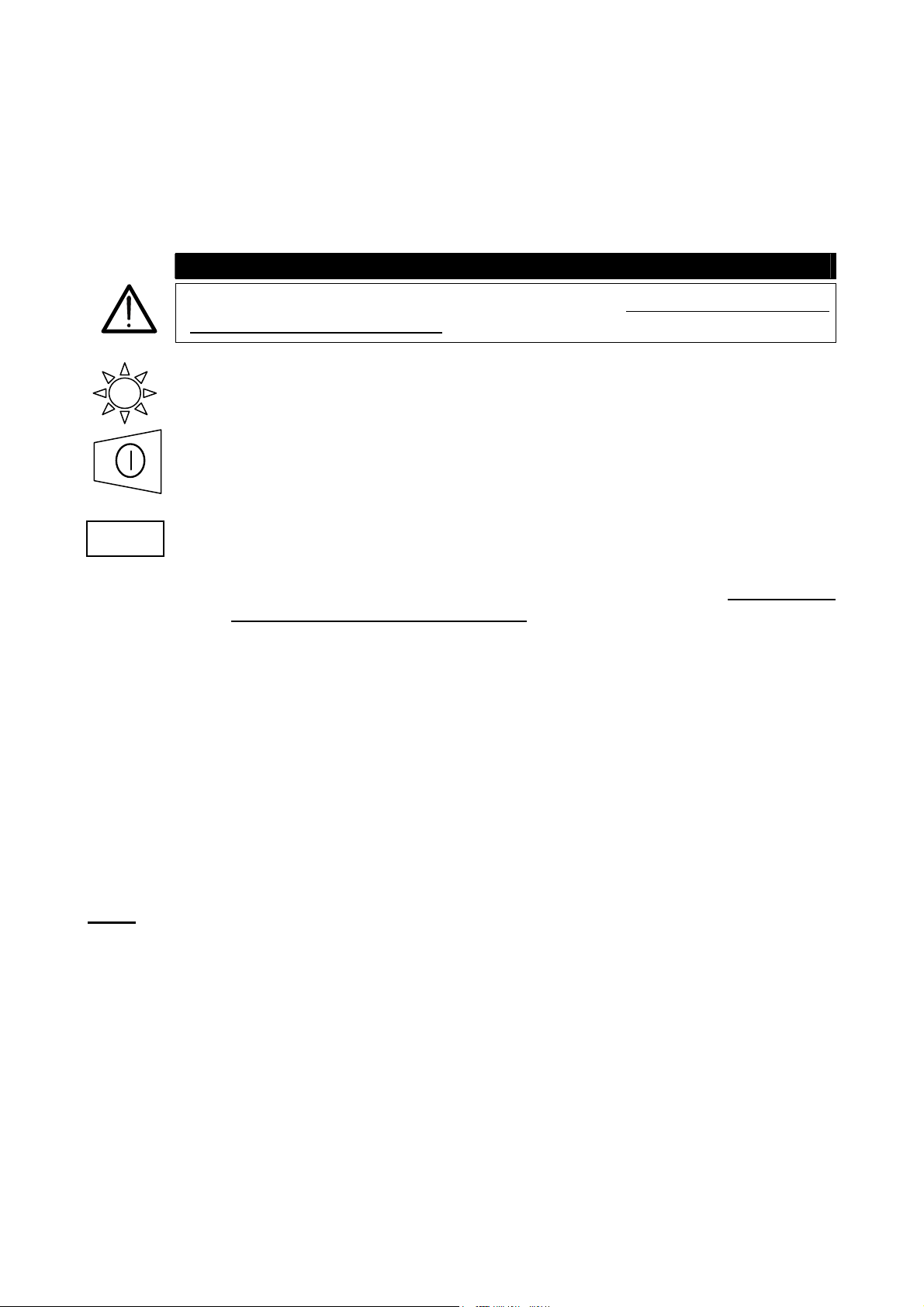
The following symbols are used in this manual:
Caution: refer to the instructions reported in this manual; improper use may
damage the apparatus or its components.
AC Voltage or Current.
Unidirectional pulsating Voltage or Current.
Rotary switch of the instrument.
WARNING
.
1.1. PRELIMINARY INSTRUCTIONS
) This instrument has been designed for use in environments with a pollution degree 2.
) It can be used for tests on electrical installations with over voltage category III up to
265V (to Earth).
) You are recommended to comply with the standard safety regulations aimed at:
9 Protecting you against dangerous currents.
9 Protecting the instrument against improper use.
) Only the leads supplied with the instrument guarantee compliance with the safety
standards. They must be in good condition and must be replaced, if necessary, with
identical models.
) Do not take measurements on circuits exceeding the specified voltage limits.
Page 5
) Do not take any measurement under environmental conditions beyond the limits
specified in this manual.
) Check that batteries have been installed correctly.
) Before connecting test leads to the circuit under test, check that the rotary switch
position is correct.
) Check that the display and rotary switch indicate the same function.
1.2. DURING USE
Carefully read the following recommendations and instructions:
WARNING
Non-compliance with the Warnings and/or Instructions may damage the
apparatus and/or its components or injure the operator
.
) Before selecting any function disconnect the test leads from the circuit under test.
) When the instrument is connected to the tested circuit never touch any test lead that is
not being used.
) Avoid taking resistance measurements in the presence of external voltages; even
though the instrument is protected, a high voltage may cause malfunctions.
WARNING
If the symbol is displayed during use interrupt testing and replace
batteries following the procedure described under paragraph 8.2. The
instrument is capable of keeping the data stored even though batteries are
not installed.
1.3. AFTER USE
) When the measurements are completed disconnect the test leads from the circuit
under test and after that switch OFF the instrument.
) Remove batteries when the apparatus remains unused for long periods of time.
Page 6

2. GENERAL DESCRIPTION
Dear Customer, we thank you for your patronage. The instrument you have just purchased
will grant you accurate and reliable measurements provided that it is used according to the
present manual’s instructions.
The instrument was designed to grant the user the utmost safety conditions thanks to a
new concept assuring double insulation and over voltage category III.
2.1. FUNCTIONS
) LOWΩ: Continuity test of earth, protective and equalizing potential conductors with
test current greater than 200mA and open circuit voltage ranging from 4V
to 24V.
) R
: Measurement of insulation resistance with DC test voltage 50V, 100V,
ISO
250V, 500V or 1000V.
)
: Indication of phase sequence.
) EARTH ρ: Measurement of earth resistance and earth resistivity.
) RS232: Rotary switch position for RS232 communications.
Page 7
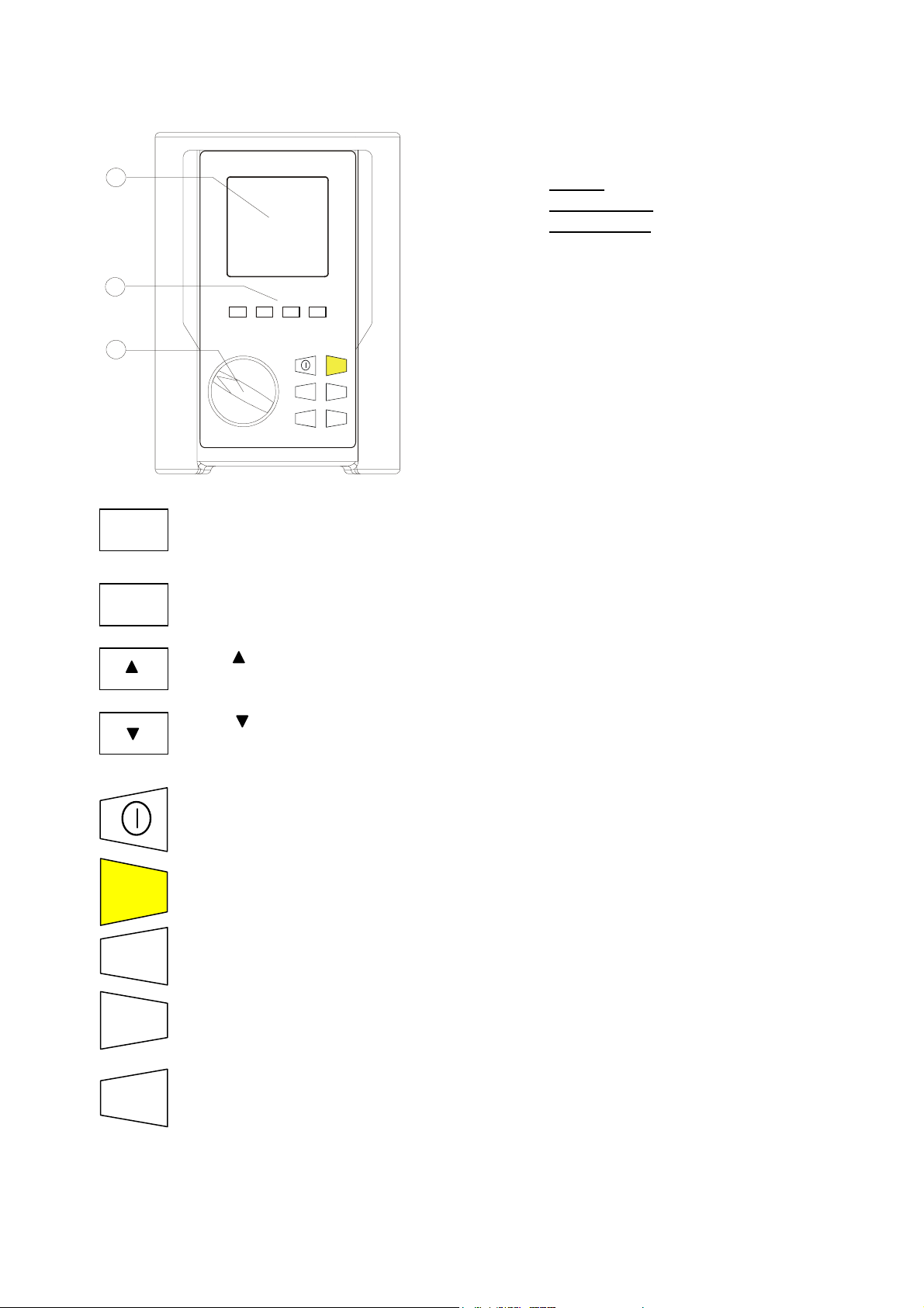
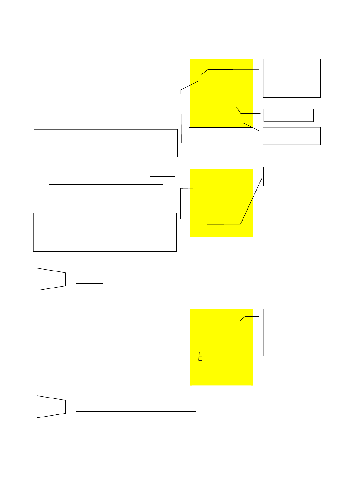
2.2. INSTRUMENT DESCRIPTION
1
2
∆
Un/I
n
FUNC
S UL
DIST
LEGEND:
1. Display
Function keys
2.
Rotary switch
3.
FUNC
START
3
Un
DIST
STOP
DISP
CLR
RCL
ESC
START
STOP
DISP
CLR
RCL
SAVE
ESC
) FUNCTION key to select measuring mode.
) U
/ DIST key for selection of rated voltage or distance depending on
n
which measurement is selected.
) key for increasing the test duration interval or to scroll the results of
the stored tests.
) key for decreasing the test duration interval or to scroll the results of
the stored tests.
) ON/OFF key. Keep it pressed a few seconds switch off the instrument.
Release when beep sounds.
) START/STOP key for start or to stop tests.
) DISPLAY key to display the stored results.
) CLEAR key to cancel the stored results.
) RECALL/ESCAPE key to recall the stored tests (RCL) and leave the
selected function or mode (ESC).
Page 8

SAVE
) SAVE key to save tests.
Page 9

3. PREPARATION FOR USE
3.1. INITIAL CONTROL
This instrument has been checked mechanically and electrically prior to shipment.
Care has been taken to ensure that the instrument reaches you under safe conditions.
However, you are recommended to perform a rapid check to detect any possible damage
that may have been caused during transport. Should this be the case, immediately contact
Amprobe.
Assure the packaging contains all the parts listed under paragraph 9.3. In case of
discrepancies contact the dealer.
In case you have to send the instrument back please follow the instructions reported in
paragraph 10.
3.2. POWER SUPPLY
Six AA batteries not included in the package supply the instrument. To replace batteries
follow the instructions in paragraph 8.2.
When batteries are low the symbol
instructions indicated in paragraph 8.2.
3.3. CALIBRATION
The instrument fulfils the technical specifications listed in this manual. The performance of
the specifications is guaranteed for one year.
3.4. STORAGE
In order to assure the accuracy of the measurements, after a period of storage in extreme
environmental conditions, wait for the instrument to return to normal operating conditions
(see environmental specifications listed in paragraph 9.2.1).
is displayed. To replace batteries follow the
Page 10
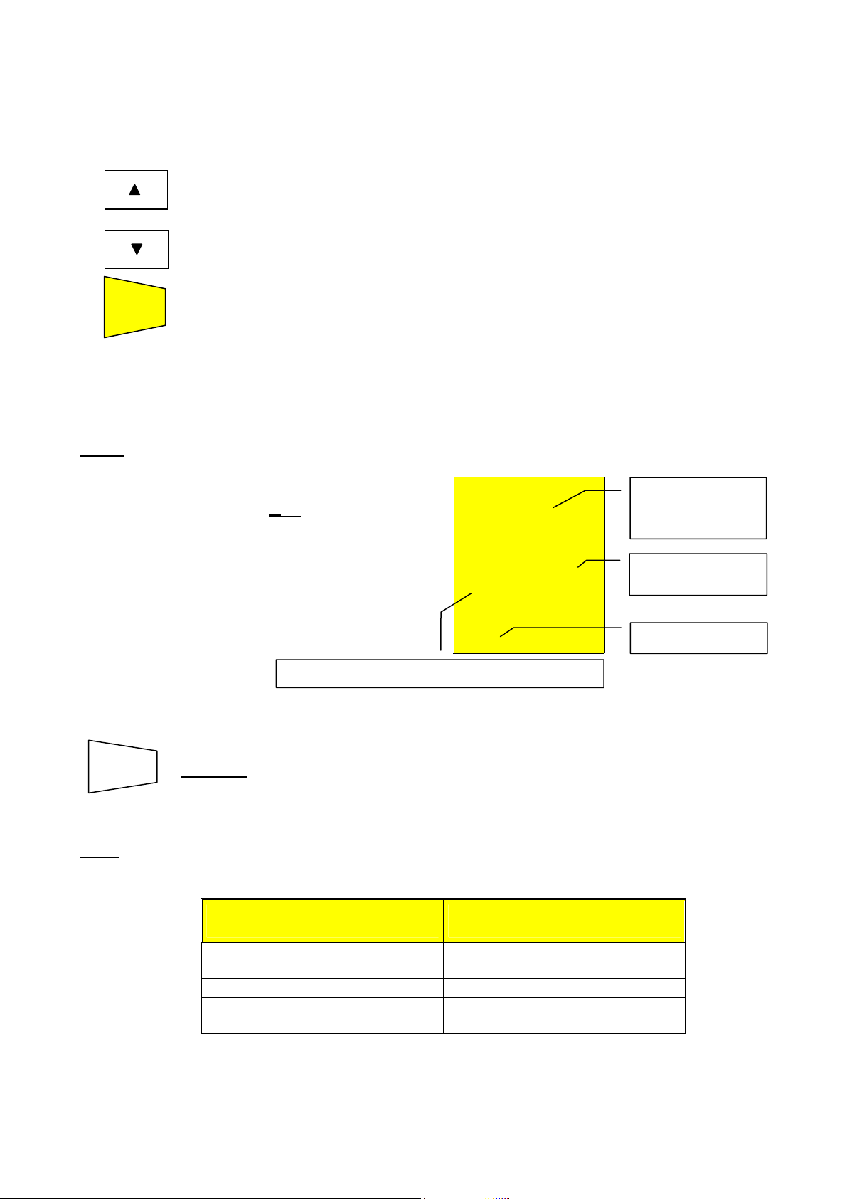
3.5. HOW TO SET LANGUAGE AND MEASUREMENT UNIT
It is possible to set the language and the distance measurement unit (in earth resistivity)
by following this procedure:
1. While pressing the FUNC button switch ON the instrument (the rotary switch position
isn't relevant).
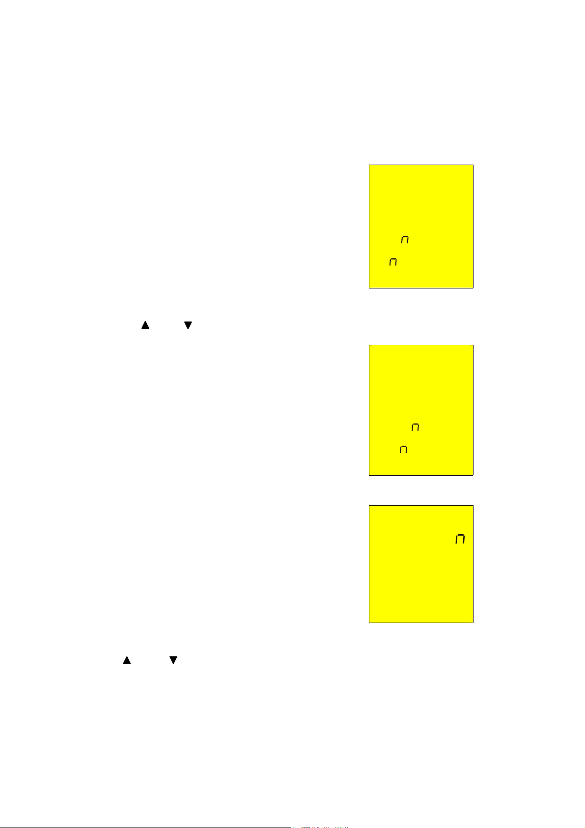
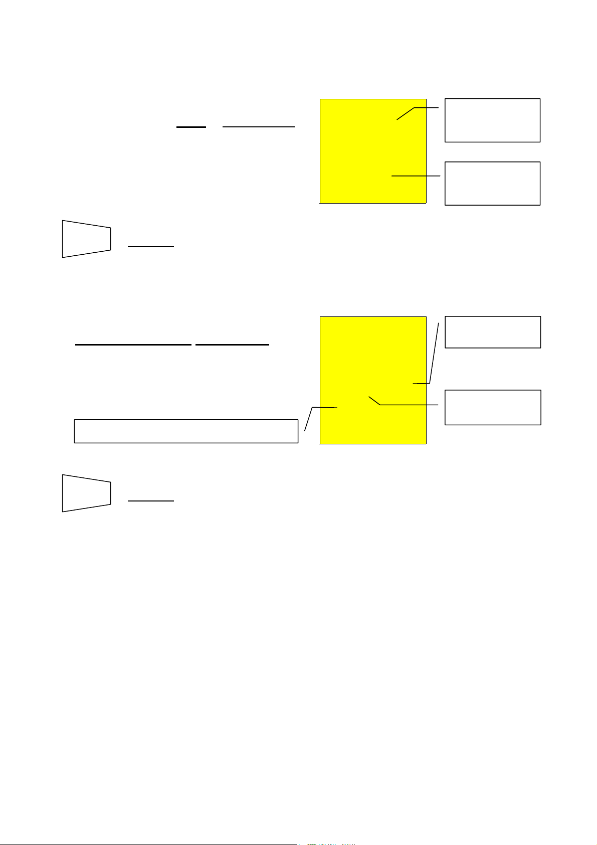
2.
)
The following screen will appear.
LA
E
3. Choose the desired language between English, Spanish, German and Italian by
pressing the and keys (appear En, ES, dE, IT).
4.
)
Push the SAVE key confirming the
choice. The instrument will display the
following screen.
)
Push ESC key leaving language
selection menu without confirming any
change.
OK
LA
E
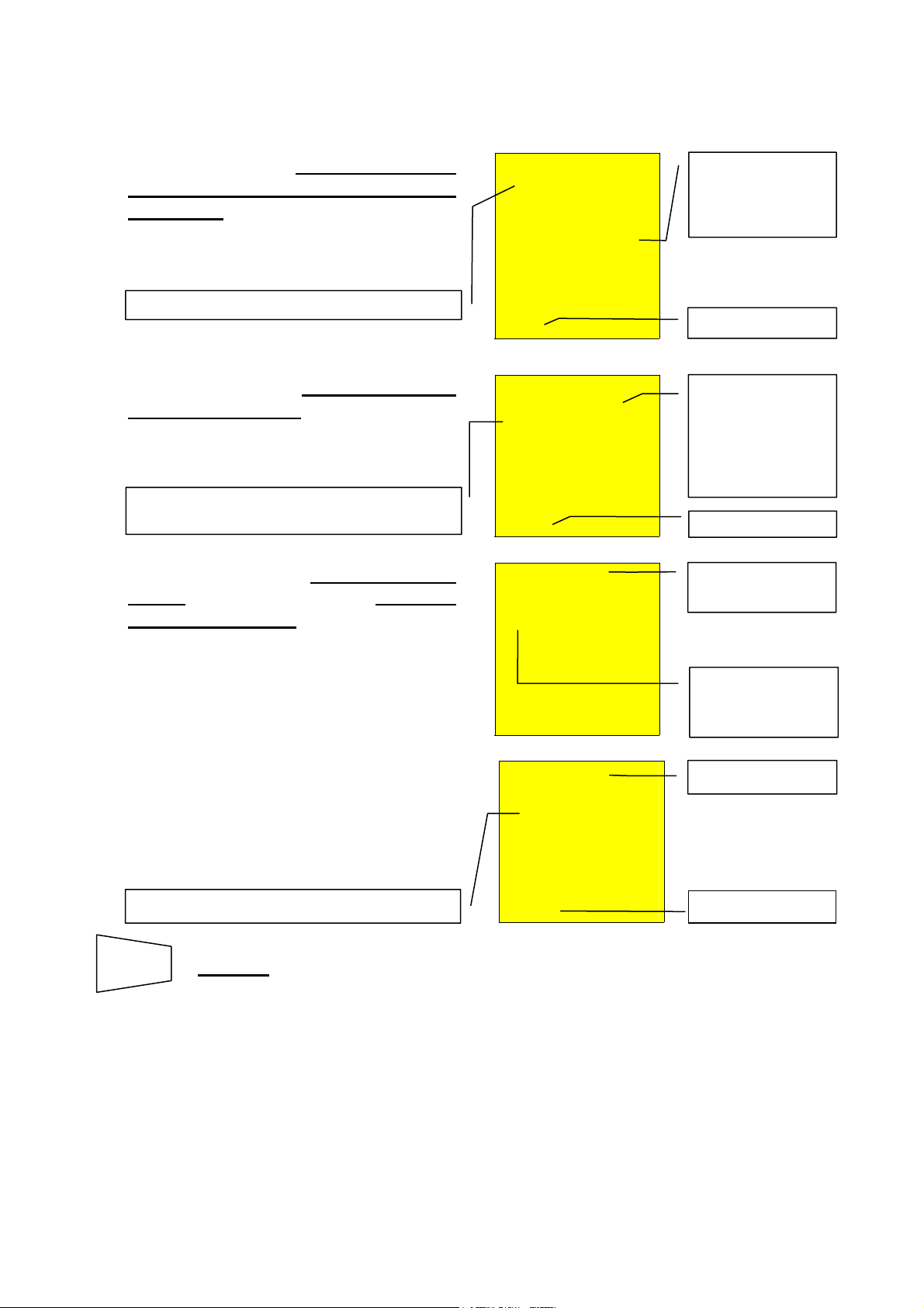
5.
)
The instrument will display the following
screen.
le
m
6. Choose the desired distance measurement unit between meter and feet that change by
pushing and keys (appear m and ft).
7.
Page 11

)
Push SAVE key confirming the choice.
The instrument will display the following
screen.
le
)
Push ESC key leaving this menu without
confirming any change.
m
OK
Page 12
4. DESCRIPTION OF THE ROTARY SWITCH FUNCTIONS
4.1. LOWΩ: CONTINUITY TEST OF EARTH RESISTIVITY, PROTECTIVE AND
EQUALIZING POTENTIAL CONDUCTORS
The measurement is performed with a test current greater than 200 mA and open circuit
voltage ranging from 4 to 24V DC according to EN 61557-2 and VDE 0413 part 4.
FUNC
Note:
If the resistance is lower than 5Ω (including the resistance of the calibration) the
Before carrying out the continuity test make sure that there is no voltage at the
ends of the conductor under test.
Turn the rotary knob to the LOWΩ position.
Switch on the instrument.
The FUNC key permits you to select one of the following measuring modes:
) AUTO mode (the instrument carries out two measurements with reversed
polarity R+ and R-, and displays their average value R
recommended for the continuity test.
) R + TIMER mode (measurement with positive polarity and the ability to
set the duration time of the test). In this case the operator can set a
measuring time long enough to permit him to move the protective
conductors while the instrument is carrying out the test to detect any bad
connection.
) R – TIMER mode (measurement with negative polarity and the ability to
set the duration time of the test). In this case the operator can set a
measuring time long enough to permit him to move the protective
conductors while the instrument is carrying out the test to detect any bad
connection.
) Mode CAL (compensation of the resistance of the cables used for the
measurement).
continuity test is performed by the instrument with a current greater than 200mA. If
the resistance is greater than 5Ω, the continuity test is performed by the
instrument using a decreasing current.
WARNING
). This mode is
avg
Page 13
A
p
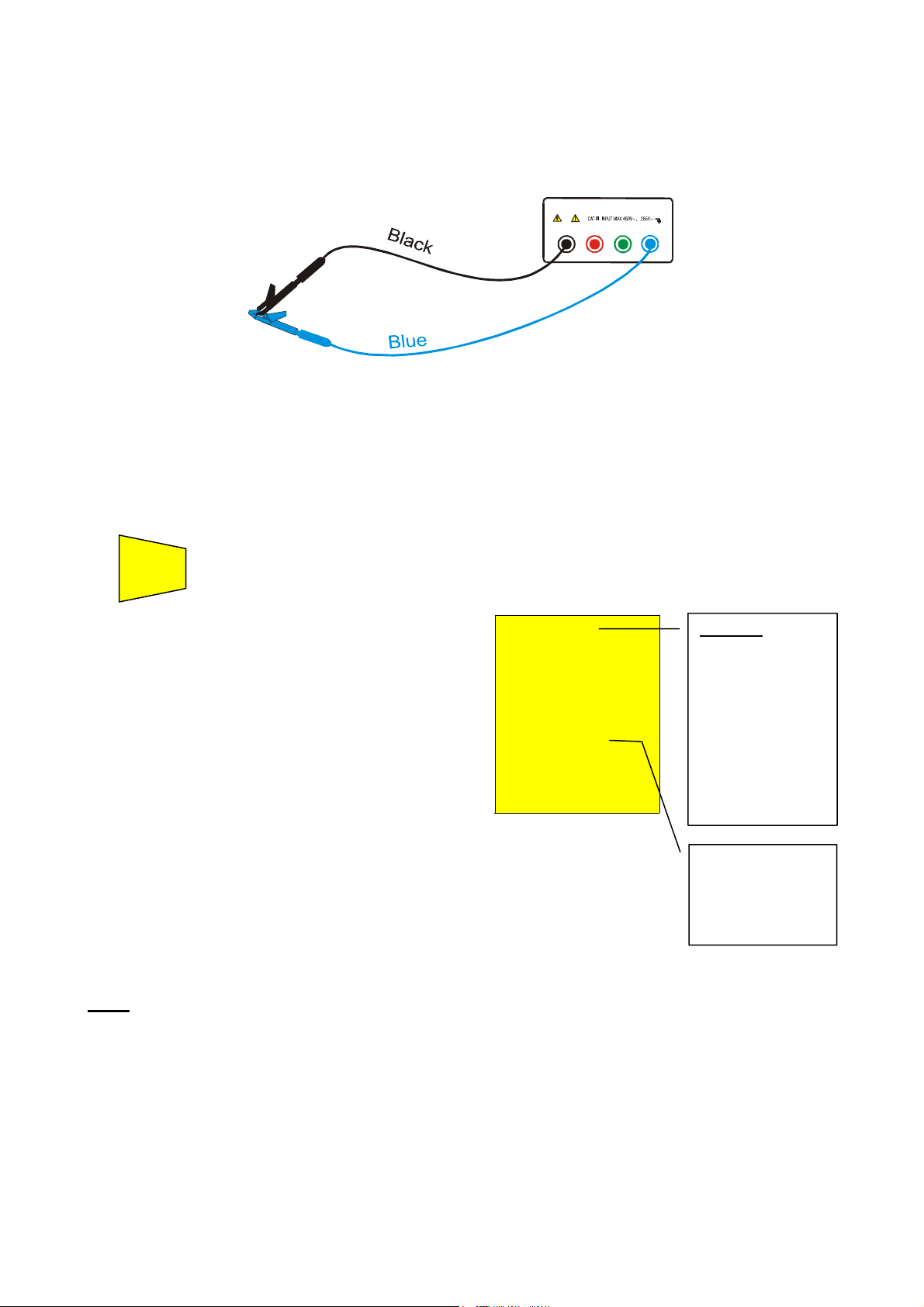
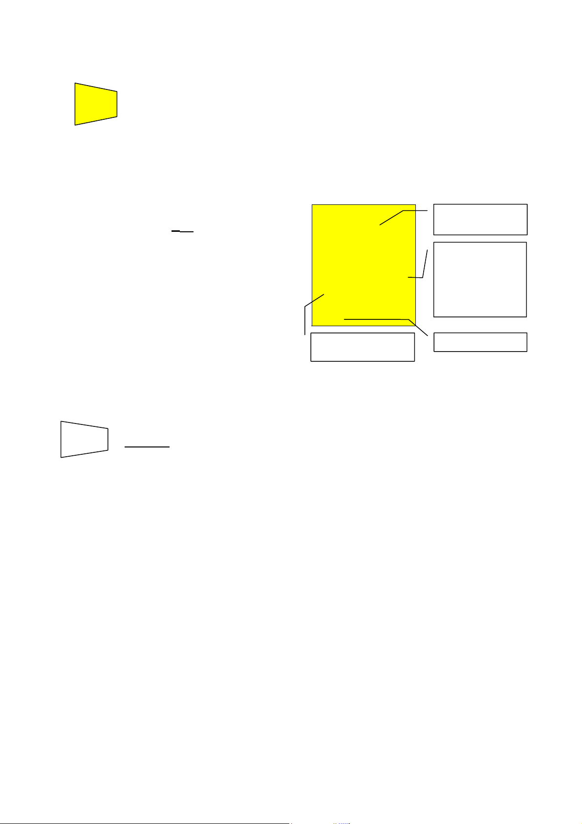
4.1.1. "CAL" Mode
1. Select the CAL mode using the FUNC key.
2. Connect the black and blue cables to the instrument input terminals T1 and T4
respectively:
B2 B3
B1
B4
Connection of instrument terminals during calibration procedure.
3. If the cables supplied with the instrument are not long enough for the measurement you can
extend the blue cable.
4. Connect the alligator clips to the cable terminals.
5. Short-circuit the measuring cable ends making sure that the conductive parts of the alligator
clips make a good contact with each other (see previous picture).
START
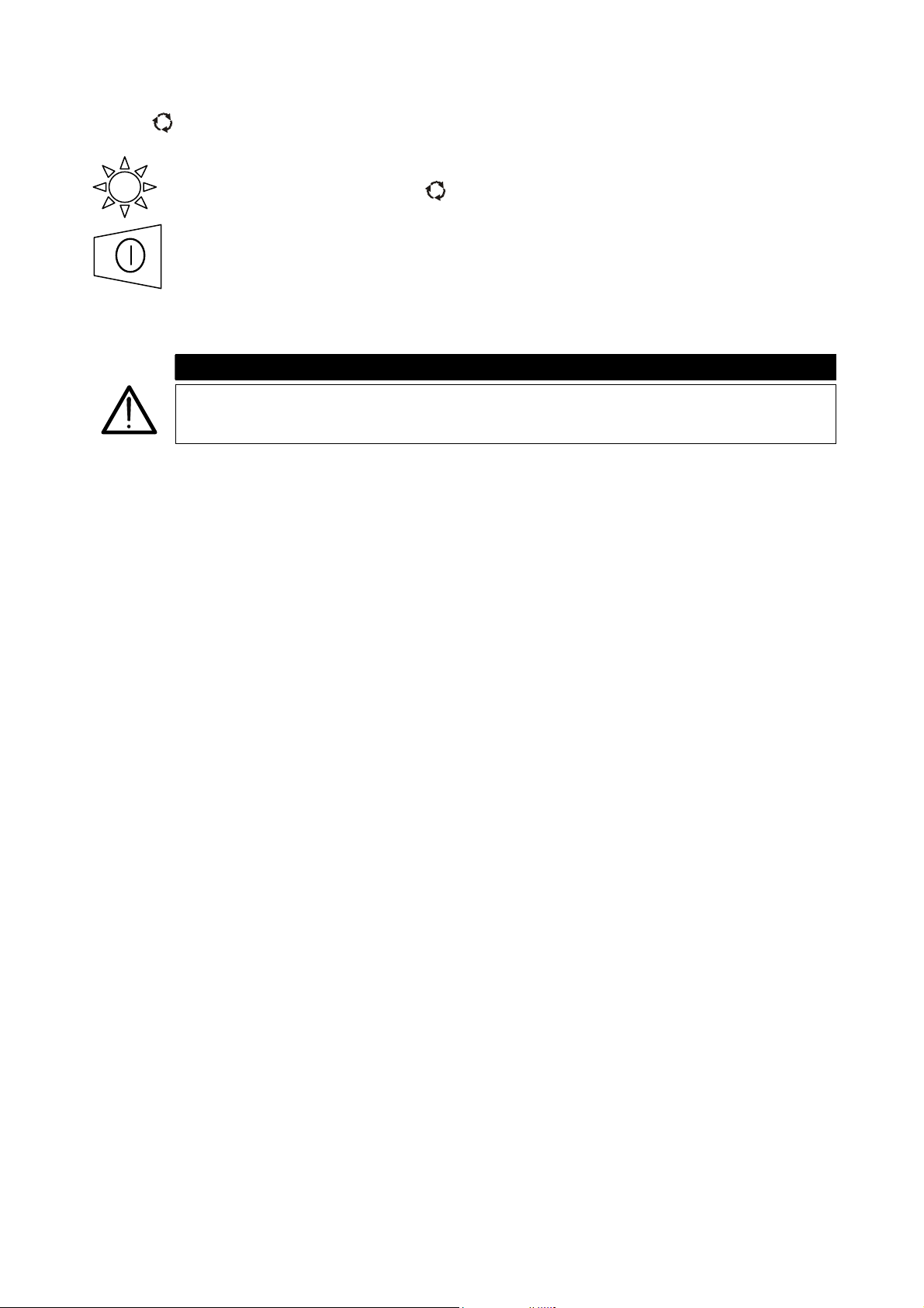
6. Press the START/STOP key. The instrument carries out the calibration.
STOP
)
t the end of the test
CAL LOWΩ
the result is stored and
used as the OFFSET
0.00
(i.e. it is subtracted
from any continuity
test performed) for all
the subsequent
measurements until a
203 mA
Ω
new calibration is
performed.
This screen is displayed for only 2 seconds
then the instrument emits a double beep
(indicating that the calibration is completed) and
displays the default screen relative to the
LOWΩ test under AUTO mode.
Message CAL:
means that the
instrument was
calibrated; this
symbol remains
on the display
for any further
measurement
even though the
unit is switched
off and on again.
Current supplied
by the instrument
during the
calibration
rocedure.
Note: The instrument effects the calibration of cables with resistance lower of 5Ω.
Page 14
Ω
CABLES USED FOR THE TEST If the cables are changed or extended be sure and
recalibrate the instrument. During a continuity
test, if the resistance value free of calibration (that
is the resistance value less the calibration offset
value) is negative, the symbols
blinking CAL are displayed (refer to 5
paragraph 4.1.3).
Never disconnect the test leads while the word “Measuring” is being
displayed.
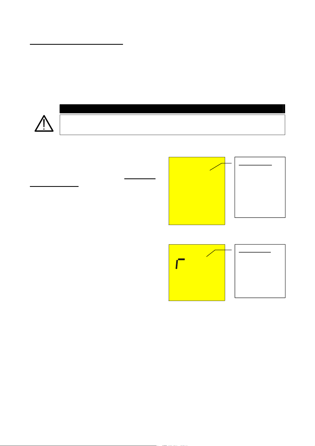
4.1.1.1. Procedure to cancel calibration parameters and cal symbol
To cancel the calibration parameters (and
the symbol CAL) it is necessary to perform a
calibration procedure with a resistance
greater than 5Ω (for example with the test
leads disconnected). When a cancellation is
completed this screen is displayed first,
followed by the screen below:
The screen alongside is displayed for 2
seconds, after which the instrument emits a
long beep and then displays the default
screen relative to the LOWΩ test under
AUTO mode without the symbol CAL.
WARNING
LOWΩ
ν> 5
cal
Measuring
LOWΩ
es
cal
ν as well as
th
screen
Message >5Ω:
means that the
instrument
detected a
resistance greater
than 5Ω therefore
it will proceed
with Reset
procedure.
Message rES:
means that the
instrument
cancelled
(RESET) the
calibration
parameter
Page 15
4.1.2. Procedure for measuring continuity of equalizing potential conductors mode
"AUTO", "R+TIMER", "R-TIMER"
1. Select the desired mode using the FUNC key.
2. Connect the black and blue cables to the instrument input terminals T1 and T4
respectively.
B2 B3
B1
B4
Connection of the instrument terminals during LOWΩ test.
3. If the cables supplied with the instrument are not long enough for the measurement you can
extend the black cable.
4. Connect two alligator clips to the cable terminals.
5. Short-circuit the measuring cable ends making sure that the conductive parts of the alligator
clips make a good contact to each other. Press the START/STOP key. If the instrument
displays a resistance value other than 0.00 repeat the instrument calibration (see
paragraph 4.1.1).
6. Connect the instrument terminals to the ends of the conductor on which the continuity test is
to be performed (see previous picture).
7. If the mode "R+TIMER" or "R-TIMER" was selected use the following keys to select
the duration time of the test:
Press this key to increase the duration time of the test (Tmax=15 seconds).
Press this key to decrease the duration time of the test (Tmin=1 second).
START
8. Press the START/STOP key. The instrument takes the measurement.
STOP
In R+/R- Timer mode
press START/STOP key again if the test is to be stopped.
WARNING
Never disconnect the test leads while the word “Measuring” is being
displayed.
Page 16
A
T
4.1.2.1. Mode "AUTO"
)
At the end of the test, if the average
resistance value Ravg
is less than 5Ω
the instrument emits a double beep
indicating the positive outcome of the
test and displays a screen similar to the
screen alongside.
SAVE
SAVING
: The test results can be stored pressing the SAVE key twice
(refer to paragraph 5.1).
4.1.2.2. Mode "R+TIMER" or “R-TIMER"
)
If during the test a resistance value
R+Timer or R–Timer less than 5Ω was
detected, the instrument (after the set
time has elapsed) emits a double beep
indicating a positive outcome of the
test & displays a screen similar to the
screen alongside.
The symbols R+ or R- are displayed.
SAVE
SAVING
: The test can be stored pressing the SAVE key twice (refer to
paragraph 5.1).
CAL LOWΩ
.07 Ω
219 mA
AUTO
CAL LOWΩ
.08 Ω
219 mA
5 s
R+
R-
IMER
Average
resistance value
Ravg.
verage test
current value
Iavg.
Duration time of
the test.
Value of the test
current I+ or I-.
Page 17
Ω
A
4.1.3. Anomalous cases during "AUTO", "R+TIMER", "R-TIMER" tests
)
In case a value of Ravg or R+ or R-
greater than or equal to 5Ω but less
than 99.9Ω was detected, at the end of
the test the instrument emits a long
beep and displays a screen similar to
the screen alongside.
ATTENTION: value of R
greater than 5
CAL LOWΩ
5.75 Ω
216 mA
5 s
AUTO
Only in the case
R+TIMER or RTIMER was
selected.
AUTO mode.
)
In AUTO mode, if a Ravg or R+ or R-
greater than 99.9Ω was detected, at
the end of the test the instrument emits
a long beep and displays the screen
alongside.
ATTENTION: value of R
high.
or R+ or R- is too
avg
CAL LOWΩ
99.9 Ω
- - - mA
AUTO
99.9Ω is the
maximum value
that can be
measured in the
LOWΩ AUTO or
R+ or R-mode.
)
In the case mode R+TIMER or RTIMER was selected and a R+ or R-
greater than 99.9Ω was detected, the
instrument emits an intermittent beep
during the test, a long beep at the
end of the test and displays the screen
alongside.
CAL LOWΩ
99.9 Ω
- - - mA 4 s
R+
TIMER
99.9Ω is the
maximum value.
ATTENTION:
value of R+ or Ris too high.
)
In case that:
R
MEASURED-RCALIBRATION
< 0Ω the
instrument displays the screen
alongside.
CAL LOWΩ
0.00 Ω
Blinking CAL.
219 mA
ATTENTION: R
MEASURED-RCALIBRATION
< 0
UTO
AUTO mode.
SAVE
SAVING
: The tests can be stored pressing the SAVE key twice (refer
to paragraph 5.1).
Page 18
A
)
If the terminal voltage is greater than
10V, the instrument does not perform
the test and displays a screen similar to
the screen alongside for 5 seconds.
fter which, the instrument displays the
screen relative to the selected test
mode LOWΩ under AUTO mode.
SAVE
THIS RESULT CANNOT BE SAVED
CAL LOWΩ
13V
VOL
AG
.
ATTENTION: the
test was not
completed
because of
voltage at the
terminal ends.
Page 19
4.2. MΩ: INSULATION RESISTANCE MEASUREMENT WITH TEST VOLTAGE
OF 50V, 100V, 250V, 500V OR 1000V
Refer to EN 61557-2 and VDE 0413 part 1.
WARNING
Before performing the insulation test make sure that the circuit under test is
not energized and all the relative loads are disconnected.
Turn the rotary knob to the MΩ position.
Switch on the instrument.
FUNC
The FUNC key permits the operator to select one of the following measuring
modes (which can be shown cyclically by pressing the FUNC key):
) MAN mode (minimum test time of 4 seconds or the key press duration of
the START/STOP key). Recommended test
.
) TIMER mode (test duration is set to the selected interval (from 10 to 999
seconds). This test can be performed in case a minimum measuring time
is required.
Page 20
4.2.1. Procedure for measuring insulation resistance in any mode
1. Select the desired mode by means of the FUNC key.
2. Connect the black and blue cables to the instrument input terminals T1 and T4
respectively.
M
B2 B 3 B4B1
Insulation between phase and earth in an electrical
installation using untied cables.
3. If the cables supplied with the instrument are not long enough for the measurement you can
extend the blue cable.
4. Connect the instrument terminals to the object that is to be submitted to the insulation
test after disconnecting the circuit under test and all the relative loads (see
previous picture).
5. By pressing the U
Un
DIST
key select the test voltage suitable for the type of
test to be carried out (see table). The values to be selected are:
n
• 50V (test on telecommunication system)
• 100V • 500V
• 250V • 1000V
Standard Brief description Test voltage Maximum limit value
> 0.250MΩ
> 0.500MΩ
> 1.0MΩ
> 50kΩ (if V<500V)
> 100kΩ (if V>500V)
> 230kΩ
> 1MΩ
CEI 64-8/6
CEI 64-8/4
Systems SELV or PELV
Systems up to 500V (Civil installations)
Systems over 500V
Floor and wall insulation in civil installations
Floor and wall insulation in systems over 500V
250VDC
500VDC
1000VDC
500VDC
1000VDC
EN60439 Electrical panel boards 230/400V 500VDC
EN60204 Electrical equipment of machines 500VDC
CEI 64-4 Floor insulation in medical rooms 500VDC
<1MΩ (if the floor is at least 1 year old)
<100MΩ (if the floor is at least 1year old)
Test voltage values and the relative maximum limit values for the most common kinds of test.
WARNING
If “Measuring” is displayed the instrument is performing the measurement.
During this phase do not disconnect the test leads, as the circuit under test
may remain charged at a dangerous voltage due to the parasite capacitance
Page 21

of the installation. Independently of the working mode selected the instrument
throws a resistance in the output terminals at the end of each test to
discharge the parasite capacitance of the circuit.
Page 22
4.2.1.1. Mode "MAN"
START
6. Press the START/STOP key.
STOP
The instrument performs the test lasting:
9 Minimum 4 seconds in case the key is pressed and released.
9 Until the key is released for all the other cases.
)
At the end of the test, in case the
resistance value R
to be lower than R
detected results
ISO
(depending on
MAX
the selected voltage see following table)
and the test is performed at the
selected rated voltage value, the
instrument emits a double beep
indicating the positive outcome of the
test displays a screen similar to the
screen alongside.
R
ISO
00 MΩ
500 V 20
s
MAN
Rated voltage value
selected for the test.
R
insulation
ISO
resistance value
Test duration.
In this case the
START/STOP
key has been
pressed for 20
seconds.
Manual mode.
.
The values of measured resistance of isolation always must be confronted with the
normative limits (see table) for being able to assert if the system is to norm.
SAVE
SAVING
: The test can be stored pressing the SAVE key twice (refer to
paragraph 5.1).
Page 23
4.2.1.2. Mode "TIMER"
6. Use the following keys to set the duration time of the test:
Press this key to increase the duration time of the test (Tmax=999 seconds).
Press this key to decrease the duration time of the test (Tmin=10 seconds).
START
7. Press the START/STOP key.
STOP
The instrument completes the measurement when the set time has elapsed.
999 seconds → Maximum value of the test duration.
10 seconds → Minimum value of the test duration.
Note:
Pressing the START/STOP key again the test gets immediately interrupted.
)
At the end of the test, in case the
resistance value R
lower than R
(depending on the
MAX
detected is
ISO
selected voltage see following table) and
the test is performed at the selected
rated voltage value, the instrument
emits a double beep indicating the
positive outcome of the test displays
one screen similar to the screen
alongside.
Rated voltage value selected for the Timer test.
R
ISO
07 MΩ
500 V 20
s
TIMER
Insulation
resistance value
R
ISO.
Duration of the
test.
Timer mode.
SAVE
SAVING
: The test can be stored pressing the SAVE key twice (refer to
paragraph 5.1).
Note
: The maximum resistance value R
on the rated voltage selected for the test. In particular:
Rated voltage selected
for the test
50VDC
100VDC
250VDC
500VDC
1000VDC
that can be measured in mode MΩ depends
MAX
R
= Maximum resistance
MAX
value
99.9MΩ
199.9MΩ
499MΩ
999MΩ
1999MΩ
Page 24

Maximum resistance values measurable under MΩ mode depend on the rated voltage selected.
Page 25
p
4.2.2. Special cases which may occur during the tests "MAN" & "TIMER"
)
In case a value of R
R
was detected (depending on the
MAX
selected voltage see following Note
table, the instrument emits a double
beep at the end of the test indicating
the positive outcome of the test and
displays a screen similar to the screen
alongside.
Maximum resistance value that can be measured
(999Ω is displayed if a rated voltage of 500V was
selected see table).
greater than
ISO
R
ISO
999 MΩ
500 V 20
s
MAN
The symbol ">"
means that the
resistance value
R
is greater
ISO
than R
Test duration
Selected mode
MAN
)
In case a test is performed at a voltage
lower than the set rated voltage, at
the end of the test the instrument emits
R
ISO
0.01 MΩ
Selected mode
MAN
a long beep and displays a screen
similar to the screen alongside.
ATTENTION: the test of resistance R
performed at a voltage value lower than the set
rated voltage. Low insulation case. This case
occurs under low insulation conditions or in the
resence of capacitance on the installation.
ISO
was
500 V 20
s
MAN
MAX
SAVE
SAVING
: The test can be stored pressing the SAVE key twice (refer to
paragraph 5.1).
)
If the terminal voltage is greater than
30V, the instrument does not perform
the test, displays the screen alongside
for 5 seconds after which, it shows the
default screen relative to the R
under selected mode.
SAVE
THIS RESULT CANNOT BE SAVED.
ISO
test
R
ISO
ν 33V
VOL
AG
ATTENTION: the
test was not
carried out.
Check that the
circuit is not
energized.
Page 26
4.3. : PHASE SEQUENCE INDICATOR
Turn the rotary knob to the
position.
Switch on the instrument.
WARNING
Never disconnect the test leads while the word “Measuring” is being
displayed.
Page 27
A
A
4.3.1. Mode " "
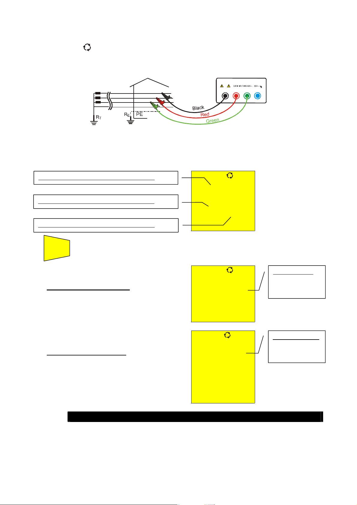
1. Connect the three black, red and green connectors of the untied cables in the corresponding
input terminals of the instrument T1, T2, T3 and the alligator clips to the free ends of the
cables.
L1
L2
L3
N
B2 B3
B1
B4
Instrument connection for phase sequence indication L1=black cable, L2=blue cable, L3=green cable
2. Connect the alligator clips to the three phases of the system under test. The instrument
displays the following screen (before pushing START/STOP key):
Voltage value between Phase1 and Phase2.
386 V
Voltage value between Phase3 and Phase1.
388V 388V
Voltage value between Phase2 and Phase3.
START
4. Press the START/STOP key to start the measurement of phase
STOP
sequence, one of the following screen will be displayed:
)
t the end of the test the instrument
displays the values alongside in case of
correct phase sequence
, which means
the black cable is connected to the
phase1=L1, the blue cable to the
phase2=L2 and green cable to the
phase3=L3.
)
t the end of the test the instrument
displays the values alongside in case of
wrong phase sequence.
123
ν
Message "123":
indicates that the
phase sequence
is correct.
Message "213":
indicates that the
phase sequence
is wrong.
213
WARNING
Page 28

SAVE
Never disconnect the test leads while the word “Measuring” is being
displayed.
SAVING
: The tests can be stored pressing the SAVE key twice (refer
to paragraph 5.1).
Page 29
p
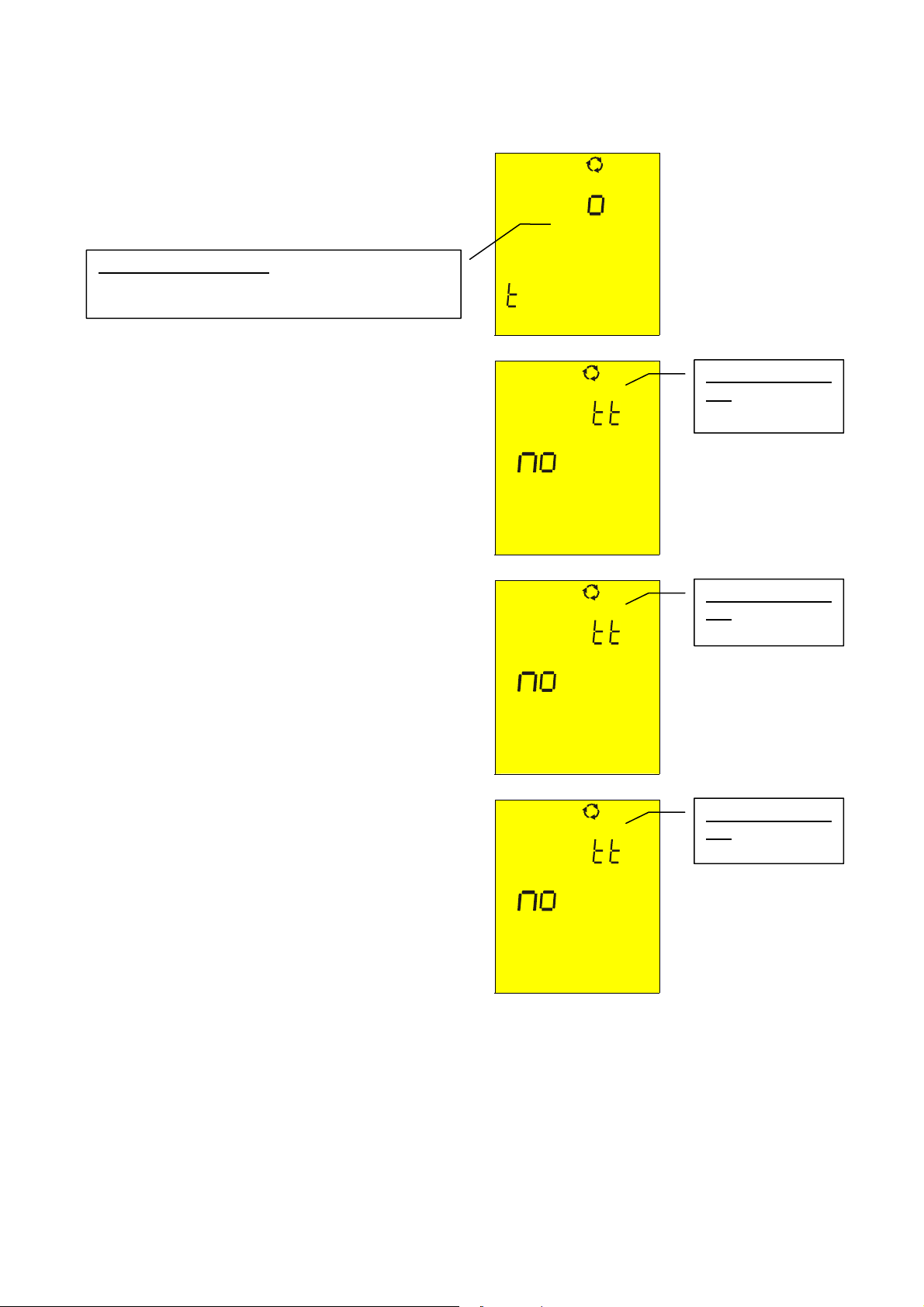
4.3.2. Anomalous cases which may occur during phase sequence tests
)
In the case that every delta voltage is
lower than 100V, the instrument does
not perform the test and displays the
screen alongside.
L
Message “Lo VOL tAG”: the instrument has at
least one low voltage. The instrument does not
perform the test.
)
If the voltage present at the T1 input is
too low, when START/STOP is pressed
the instrument displays the message
alongside.
)
If the voltage present at the T2 input is
too low, when START/STOP is pressed
the instrument displays the message
alongside.
VOL
AG
ν A
l1
ν A
Message “Att no
L1”: voltage of
phase 1 is too low
Message “Att no
L2”: voltage of
phase 2 is too low
)
If the voltage present at the T3 input is
too low, when START/STOP is pressed
the instrument displays the message
alongside.
l2
ν A
l3
Message “Att no
L3”: voltage of
hase 3 is too low
Page 30
)
If two measurement cables were
connected to the same phase
conductor, when START/STOP is
pressed the instrument displays the
message alongside.
SAVE
THE PREVIOUS RESULTS CANNOT BE SAVED
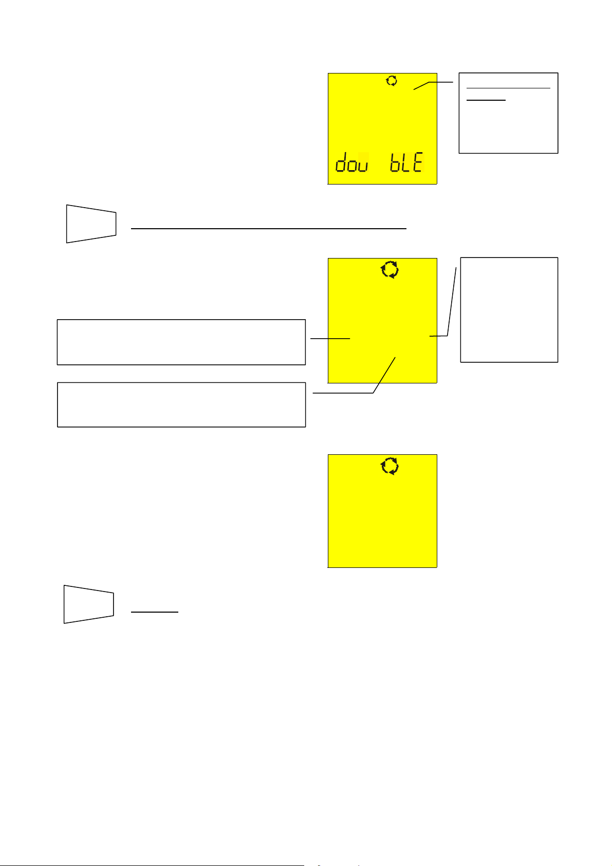
)
If one cable is not connected to the
network or one phase is absent, the
instrument displays the screen
alongside
Black cable=L1 is not connected to one phase of
the installation. Voltage between phase L3 and
phase L1 is null (L3 - L1).
ν ph
.
0 V
0 V 388
V
Message “PH
double”: two
cables are
connected to the
same phase
conductor.
Black cable= L1
is not connected
to one phase of
the installation.
Voltage between
phase L2 and
phase L3 is not
null (L2- L3).
Black cable=L1 is not connected to one phase of
the installation. Voltage between phase L1 and
phase L2 is null (L1-L2).
)
If two or more cables of the instrument
are not connected, it displays the screen
alongside.
SAVE
SAVING
: The tests can be stored pressing the SAVE key twice (refer
to paragraph 5.1).
0 V
0 V 0 V
Page 31

4.4. EARTH ρ: EARTH RESISTANCE AND RESISTIVITY MEASUREMENT
Turn the rotary knob to the EARTH ρ position.
FUNC
The resistance is measured with a 4-cable voltamperometric method, so the value
measured is not dependant on the utilized cables. For this reason this method doesn’t
need any cable calibration.
If the cables aren’t long enough, lengthen them or utilize cables longer than the standard
ones.
Switch on the instrument.
The FUNC key permits to select one of the following measuring modes
(which can be shown cyclically when pressing the key):
) Mode “2P” (the instrument measures earth resistance between 2 points).
) Mode “3P” (the instrument measures earth resistance using two auxiliary
earth rods).
) Mode “ρ“ (the instrument measures earth resistivity).
Page 32

A
play
4.4.1. Measurement procedure for "2P" test mode
1. Select "2P" earth measurement mode using the F1 key.
2. Connect the Black, Red, Green and Blue cables to the corresponding input terminals of the
instrument T1, T2, T3, T4 (see possible connections in the following picture).
3. Connect the black, and green cables to the earth plant and red and blue cables to the
auxiliary rod.
B2 B3
B4B1
2 points earth resistance measurement
START
4. Press the START/STOP key. The instrument starts the test.
STOP
)
t the end of the test the instrument
displays the values alongside.
EARTH
Resistance value
measured
0.96
Average value of earth resistance calculated over
the number of test dis
ed.
2P
0.93 Ω
WARNING
Ω
Mode “2P”.
Never disconnect the test leads while the word “Measuring” is being
displayed.
SAVE
SAVING
: The tests can be stored pressing the SAVE key twice (refer
to paragraph 5.1).
Note
: If START/STOP key was pressed and held, the instrument takes more
consecutive tests.
5. When a new value is acquired the instrument emits a short sound and calculates the
new average value.
Page 33

6. Press the DISP key to show how many measurements are in average
DISP
value calculation and the measuring mode.
7. Press CLR key if you want to cancel the medium value of the resistance
CLR
and the number of measurements that are included in the calculation.
Page 34

When the environmental conditions preclude the “3P” measurement mode, as for example
in a city center. In TT plants it is possible to measure the earth resistance with the
simplified “2P” method that gives a higher value than the “3P” mode does.
An auxiliary rod is necessary; it must have an insignificant earth resistance and must be
independent of the earth plant under test.
In the picture above, a water tube is used as the auxiliary rod. But, any metallic object
fixed to the ground could replace it.
Example: if the operator takes three consecutive measurements, the instrument displays
st
1
measurement:
main display = measured resistance value (Ex: 0.90Ω)
secondary display on the left-hand side = 001 (no. of measurements = 1
means that 1 earth measurement has been taken)
secondary display = average of the measurements taken (in case just one
measurement has been taken the medium value is equal to the measured
value, in this case 0.90Ω)
nd
2
measurement:
main display = measured resistance value (Ex: 0.96Ω)
secondary display = average of the measurements taken ((Val1+Val2)/no.
of measurements = (0.90+0.96)/2 = 0.93Ω)
3rd measurement:
main display = measured resistance value (Ex: 0.93Ω)
secondary display = average of the measurements taken ((Val1+Val2)/no.
of measurements = (0.90+0.96+0.93)/3 = 0.93Ω)
Note
: Any test with a result over 1999Ω is not inserted in the calculation of medium
value.
Example: 1
st
measurement:
main display: 1.07Ω
secondary display: 1.07Ω
2nd measurement
main display: 4.15Ω
secondary display: 2.61Ω
rd
measurement (not inserted in the medium value)
3
main display: >1999Ω
secondary display: 2.61Ω
Page 35

4.4.1.1. Earth resistance measurement from a socket
On TT installations it’s possible to take an earth measurement with a simplified method
that gives an excess value (therefore safer), using the NEUTRAL of the national Energy
Board taken directly from a socket as an auxiliary rod; if also the earth connection is
available, naturally the measurement can be taken on the socket directly, between
NEUTRAL and EARTH.
Although this test is not provided for by CEI 64.8 at present, it gives a value which many 3wires comparison tests proved to be revealing for earth resistance.
B2 B3
B4B1
Earth measurement with simplified method on panel board
WARNING
If you want to take the measurement using the neutral and the earth of a
standard wall socket, you may accidentally connect to the hot leg. In this
case the display will show the voltage, the symbol
(wrong insertion) and
won’t take any measurement even if START/STOP is pressed.
WARNING
Never disconnect the test leads while the word “Measuring” is being
displayed.
Page 36

A
A
the number of test displayed
4.4.2. Measurement procedure for "3P" test mode
The measurement is taken according to what is prescribed for CEI 64.8, IEC 781, VDE
0413, EN61557-5.
1. Select "3P" earth measurement mode using the F1 key.
2. Connect the Black, Red, Green and Blue cables to the corresponding input terminals of the
instrument T1, T2, T3, T4 (see possible connections in the following picture).
3. Connect the black, and green cables to the earth plant and red and blue cables to the
auxiliary rods.
B2
B4B1
B3
3 points earth resistance measurement
Measuring small earth plants, current probe must be positioned a distance from the earth
equipment outline corresponding to five times the diagonal of the area of the earth
equipment under test, measuring big earth plants this distance could be reduced up to one
times the diagonal.
START
4. Press the START/STOP key. The instrument starts the test.
STOP
)
t the end of the test the instrument
displays the values alongside.
EARTH
Resistance value
measured
0.96
verage value of earth resistance calculated over
.
2P
0.93 Ω
WARNING
Ω
Mode “2P”.
The display of “Measuring” means that the instrument is measuring. During
this phase never disconnect test leads.
Page 37

SAVE
SAVING
: The tests can be stored pressing the SAVE key twice (refer
to paragraph 5.1).
Page 38

Note: If the START/STOP key was pressed and held, the instrument takes more
consecutive tests.
5. When a new value is acquired the instrument emits a short sound and calculates the
new average value.
6. Press DISP key to show how many measurements are in average value
DISP
calculation and the measuring mode.
CLR
7. Press CLR key if you want to cancel the medium value of the resistance
and the number of measurements which are included in the calculation.
Example: if the operator takes three consecutive measurements, the instrument displays
st
1
measurement:
main display = measured resistance value (Ex: 0.90Ω)
secondary display on the left-hand side = 001 (no. of measurements = 1
means that 1 earth measurement has been taken)
secondary display = average of the measurements taken (in case just one
measurement has been taken the medium value is equal to the measured
value, in this case 0.90Ω)
nd
2
measurement:
main display = measured resistance value (Ex: 0.96Ω)
secondary display = average of the measurements taken ((Val1+Val2)/no.
of measurements = (0.90+0.96)/2 = 0.93Ω)
3rd measurement:
main display = measured resistance value (Ex: 0.93Ω)
secondary display = average of the measurements taken ((Val1+Val2)/no.
of measurements = (0.90+0.96+0.93)/3 = 0.93Ω)
: Any test with result over 1999Ω is not inserted in the calculation of medium value.
Note
Example: 1
st
measurement:
main display: 1,07Ω
secondary display: 1,07Ω
nd
measurement
2
main display: 4,15Ω
secondary display: 2,61Ω
rd
measurement (not inserted in the medium value)
3
main display: >1999Ω
secondary display: 2,61Ω
Page 39

4.4.3. Measurement procedure for "ρ" test mode
The earth resistivity is a very useful measurement. Its’ value can help a designer correctly
size the earth rods in an earth plant.
The measurement is taken according to what is prescribed for CEI 64.8, IEC 781, VDE
0413, EN61557-5
1. Select "ρ" earth measurement mode using the F1 key.
2. Connect the Black, Red, Green and Blue cables to the corresponding input terminals of the
instrument T1, T2, T3, T4 (see possible connections in the following picture).
3. Connect the cables to the auxiliary rods (see connections in the following picture).
B2 B3 B4B1
a
a
a
a
Earth resistivity measurement
4. To select the distance DIST between the rods. This parameter can be set
Un
DIST
from 1 to 10 meters or 3 to 30 feet.
)
At the end of the test the instrument
-ρ
displays the values alongside.
5
m
SE LE
Distance between the rods set value.
5. Press and keys to select the distance value.
6. Press ESC key to leave this menu confirming the settings.
RCL
ESC
START
STOP
Page 40

A
7. Press the START/STOP key. The instrument starts the test.
)
t the end of the test the instrument
ρ
displays the values alongside.
36.5
Earth resistivity value
Ωm
2
0.93 Ω
WARNING
Never disconnect the test leads while the word “Measuring” is being
displayed.
SAVE
SAVING
: The tests can be stored by pressing the SAVE key twice
(refer to paragraph 5.1).
Note
: If START/STOP key is pressed & held, the instrument takes more consecutive
tests.
8. When a new value is acquired the instrument emits a short sound and calculates the
new average value.
9. Press DISP key to show how many measurements are in average value
DISP
calculation and the measuring mode.
10. Press CLR key if you want to cancel the medium value of the resistance
CLR
and the no. of measurements which are included in the calculation.
Note
: Any test with result over 1999Ω is not inserted in the calculation of medium value.
Example: 1
st
measurement (D=1):
main display: 6,6Ωm
secondary display: 6,6Ωm
nd
measurement (D=1):
2
Page 41

main display: 4,15Ω
secondary display: 2,61Ω
rd
measurement (not inserted in the medium value)
3
main display: >1999Ω
secondary display: 2,61Ω
4.5. ANOMALOUS CASES WHICH MAY OCCUR DURING EARTH ρ TESTS
)
If the amperometric circuit is
interrupted, when pressing
START/STOP the instrument can’t read
- - -
the minimum current, therefore a
rC indicates a
high resistance
value.
screen similar to the one beside
appears. Make sure that the terminals
are connected correctly and that the
amperometric rod (blue conductor) has
not been driven into non-conductive
- - - c
ground. If necessary, pour water
around the rod.
SAVE
THE PREVIOUS RESULTS CANNOT BE SAVED
.
)
If the instrument measures an
interfering voltage greater than 30V
on the amperometric circuit, it
doesn’t perform the test and a screen
similar to the one beside appears.
31 V
Voltage value on the amperometric circuit
SAVE
THE PREVIOUS RESULT CANNOT BE SAVED
VOL
AG
.
Page 42

)
If the resistance measured is greater
than the full scale of the instrument,
after pressing START/STOP the
instrument performs the test and a
screen similar to the one beside
appears.
)
If the resistivity measurement is greater
than the following value
1999x6.28x(distance between the rods
selected), after pressing START/STOP
the instrument performs the test and a
screen similar to the one beside
appears.
SAVE
SAVING
: The tests can be stored pressing the SAVE key twice (refer
to paragraph 5.1).
>1999 Ω
- - -
- - -
1999 Ω
- - -
- - -
1999Ω is the full
scale of the
instrument.
1999Ω is the full
scale of the
instrument.
Page 43

5. HOW TO SAVE, RECALL AND CLEAR DATA STORED IN MEMORY
5.1. SAVE: "SAVE" KEY
If the results relative to the tests performed are to be stored you can proceed as follows:
SAVE
1. Press the SAVE key once.
)
If the memory of the instrument is not
MEM
empty it displays the screen alongside.
Number of the memory location in which the
measurement results will be stored.
3
PLA
Value of the parameter PLA related to the
measurement to be saved.
02
2. Use the & keys to increase or decrease the value of the PLA
(Place) parameter
to be related to the measurement that is to be
saved. This parameter helps the operator to classify the tests
performed.
Example: If the tests are to be carried out in a building, the operator
can associate the measurements performed in a room
with a given value of the parameter PLA. In this way
different values of the parameter PLA will correspond to
different rooms.
SAVE
3. Press the SAVE key again, the instrument emits two beeps,
confirming that the test results have been stored.
RCL
ESC
Press RCL/ESC key at any time
back to the measurement selected.
to leave the memory menu and go
Page 44

5.2. RECALL: "RCL" KEY
If you want to recall
the stored test results proceed as follows:
RCL
1. Press the RCL/ESC key.
ESC
)
If the memory of the instrument is not
empty it displays the screen alongside.
Number of the memory location in which the
measurement result was stored.
MEM
3
Pla
Value of the parameter PLA related to the
saved measurement
02
2. Use the & keys to select the memory location number to be
displayed.
3. Press the DISP key to display the test result related to the selected
DISP
memory location.
4. Use the & keys again if you want to display again the numbers of
memory locations.
RCL
ESC
Press RCL/ESC key at any time
to the measurement selected.
to leave the memory menu and go back
Page 45

5.3. CLEAR: "CLR" KEY
If you want to cancel
the stored tests results proceed as follows:
RCL
1. Press the RCL/ESC key. The instrument displays a screen like the
ESC
following:
Number of the memory location in which the
measurement result was stored.
MEM
3
Value of the parameter PLA related to the
saved measurement.
Pla
02
2. Use the & keys to select the number of the memory location.
ATTENTION: The instrument will cancel all the results stored from the memory location
selected to the last.
3. Press the DISP key to display the test result related to the memory
DISP
location selected.
CLR
4. Press CLR once. The blinking
symbol "clr" is displayed. Now you face
two possibilities:
Last location with data stored.
MEM
C i
The instrument cancels the memory cells from
n.2 to n.8, where n.2 is the one selected by
the operator while n.8 is the last test saved in
the instrument.
02
08
CLR
Press CLR again if the tests selected are to be cancelled
starting from the one selected down to the last one saved.
RCL
ESC
Page 46

Press RCL/ESC to nullify the clearing phase. The blinking
symbol "clr" disappears.
RCL
ESC
Press RCL/ESC key at any time
to the measurement selected.
to leave the memory menu and go back
Page 47

6. RESET OF THE INSTRUMENT AND DEFAULT PARAMETERS
BEFORE OF A RESET PROCEDURE DOWNLOAD THE STORED TESTS ON A PC
6.1. RESET PROCEDURE
1. Press the DISP, CLR, RCL keys and then ON/OFF key.
2.
The screen alongside is
displayed for 5 seconds, after
which the instrument emits a beep
and then displays the screen
relative to the function selected
with the rotary switch.
ATTENTION: the reset procedure will cancel all the stored tests and it will set the
default parameters in the instrument.
6.2. DEFAULT PARAMETERS
After a RESET the default parameters set on the instrument are:
es
Function Parameter RESET default parameter
Mode AUTO
LOWΩ
Calibration Offset
Mode R+/R- TIMER
TIMER is set at 1s
0
Mode MAN
R
ISO
EARTH ρ
Memory
Test voltage 500V
Mode TIMER TIMER is set at 60s
Parameter DIST DIST = 1
Parameter PLA P = 1
Memory state 0
Page 48

7. INSTRUMENT CONNECTION TO A PC
The connection between PC and instrument is created using the serial port and optical
serial cable, provided with the software package.
Before making the connection it is necessary to select the COM port used for the
transmission. To set this parameter start the software and look up the help on line.
ATTENTION
To transfer the stored data from the instrument to the PC keep to the following procedure:
FUNC
: The selected port shall NOT be shared by other devices or applications
(example mouse, modem, etc.)..
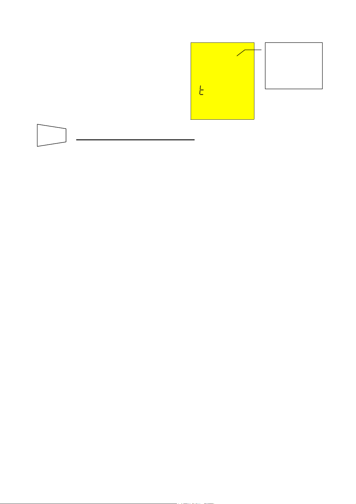
1. Turn the switch on position RS232.
2. By means of the FUNC key select the mode "SEr":
Then proceed according to the software instruction manual to transfer the
measurements performed.
)
The communication between
instrument and PC occurs.
SE
Note
: The download speed is: 9600 baud (see software instruction manual).
Page 49

8. MAINTENANCE
8.1. GENERAL
1. The instrument you have purchased is a precision instrument. Strictly follow the
instructions for use and storage reported in this manual to avoid any possible damage
or danger during use.
2. Do not use this tester under unfavorable conditions of high temperature or humidity. Do
not expose to direct sunlight.
3. Be sure to turn off the tester after use. If the instrument is not to be used for a long
period you are recommended to remove the batteries to avoid acid leakage that may
damage the internal circuits of the instrument.
8.2. BATTERY REPLACEMENT
When the symbol
Only skilled technicians can perform this operation. Before replacing batteries
make sure that all test leads have been disconnected from input terminals. The
instrument will retain the data stored even though the batteries are not
installed.
1. Switch OFF the instrument.
2. Remove all the test leads from the input terminals.
3. Unscrew the fixing screw from the battery compartment cover and remove it.
4. Remove all batteries replacing them with 6 new ones.
5. Fix the screw on the battery compartment cover.
8.3. INSTRUMENT CLEANING
Use a soft dry cloth to clean the instrument. Never use wet cloths, solvents, water, etc.
is displayed batteries are to be replaced.
WARNING
Page 50

9. TECHNICAL SPECIFICATIONS
9.1. TECHNICAL FEATURES
Accuracy is indicated as [% of reading + number of digits]. It refers to the atmospheric
conditions listed in paragraph 9.2.1.
- Continuity (LOWΩ)
Test mode
AUTO, R+TIMER, R-TIMER
Test current >200mA DC up to 5Ω (include the resistance of the calibration)
Test current resolution 1mA
Open circuit Test Voltage 6V < V0 < 12V
Measuring range (Ω) Resolution (Ω)
0,01 – 19,99 0,01
20,0 – 99,9 0,1
- Insulation resistance (R
Test voltage (V)
50
100
250
500
1000
ISO
)
Measuring range (Ω) Resolution (Ω)
0,01 - 19,99 0,01
20,0 - 49,9 0,1
50,0 - 99,9 0,1
0,01 - 19,99 0,01
20,0 - 99,9 0,1
100,0 - 199,9 0,1
0,01 - 19,99 0,01
20,0 - 199,9 0,1
200 - 249 1
250 - 499 1
0,01 - 19,99 0,01
20,0 - 199,9 0,1
200 - 499 1
500 - 999 1
0,01 - 19,99 0,01
20,0 - 199,9 0,1
200 - 999 1
1000 - 1999 1
Accuracy
±(2% rdg + 2 dgt)
Accuracy
±(2% rdg + 2 dgt)
±(5% rdg + 2 dgt)
±(2% rdg + 2 dgt)
±(5% rdg + 2 dgt)
±(2% rdg + 2 dgt)
±(5% rdg + 2 dgt)
±(2% rdg + 2 dgt)
±(5% rdg + 2 dgt)
±(2% rdg + 2 dgt)
±(5% rdg + 2 dgt)
Automatic selection of the measuring range
Open circuit voltage Rated voltage test –0% +10%
Short circuit current <6,0mA with 500V set
Rated measuring current >2,2mA with 500V on 230kΩ
1mA a 1KΩ x V
(≠ 500 V)
NOM
- AC voltage
Measuring range (V) Resolution (V) Accuracy
0 ÷ 460
1
- Earth resistance measurement with voltamperometric method
Measuring range (Ω) Resolution (Ω)
0,01 ÷ 19,99
20,0 ÷ 199,9
200 ÷ 1999
Test current <10mA 77,5Hz
Open load test voltage <20V RMS
0,01
0,1
1
±(3% rdg + 2 dgt)
Accuracy
±(5% rdg + 3 dgt)
Page 51

Page 52

- Earth resistivity ρ measurement
Measuring range (Ω) Resolution (Ωm)
0.06 ÷ 19,99 Ωm 0,01 Ωm
20.0 ÷ 199.9 Ωm 0.1 Ωm
200 ÷ 1999 Ωm 1 Ωm
2,00 ÷ 19,99 kΩm 0.01 kΩm
20.0 ÷ 125,5 kΩm (*) 0.1 kΩm
(*) with D = 10m
Test current <10mA 77,5Hz
Open load test voltage <20V RMS
Accuracy
±(5% rdg + 3 dgt)
9.1.1. Safety standards
The instrument complies with: EN 61010-1 + A2(1997)
Product norms: IEC61557-1, -2, -3, -4, -5, -6
Insulation: Class 2, double insulation
Pollution level: 2
Inside use; max height: 2000m
Overvoltage category: CAT III 460V∼ T1-T2-T3-T4 / 265V∼ to earth
9.1.2. General specifications
Mechanical features
Dimensions: 222(L) x 165(La) x 105(H)mm
Weight (batteries included): approx. 1200g
Power supply
Battery type: 6 batteries 1.5 V – LR6 – AA – AM3 – MN 1500
Low battery indication: The symbol is displayed when the battery
voltage is too low.
Battery life: About 40 hours in stand-by or
500 LowΩ tests or
250 R
tests 500V/500kΩ or
ISO
1000 Loop, phase sequence tests
300 Earth or ρ tests.
Display: LCD custom 65mmx65mm
Memory: 350 tests
Serial interface: opto-isolated RS232 to download stored data to a
PC.
Page 53

9.2. ENVIRONMENT
9.2.1. Environmental working conditions
Reference temperature: 23° ± 5°C
Working temperature: 0°C ÷ 40 °C
Relative humidity allowed: <80%
Storage temperature: -10 ÷ 60 °C
Storage humidity: <80%
9.2.2. EMC
This instrument was designed in compliance with the EMC standards in force and its
compatibility has been tested for EN61326-1 (1998) + A1 (1999).
This instrument conforms to European directive for CE standards.
This instrument complies with the requirements of the European Low Voltage
Directives 73/23/CEE and EMC 89/336/CEE, amended with 93/68/CEE.
9.3. ACCESSORIES
The accessories provided with the instrument depend on the model purchased according
to the following table. The accessory is named standard when it is sold together with the
instrument in a single package.
Standard accessories
Description Code Description Code
Set with 4 cables, 4 alligator
clips and 2 test leads
alligator clip) and 4 rods
MTL-MT1 Software and Manual
GP2-CON
Serial cable C2001 Bag with 4 cables (bananaCarrying case CC-MT1
Optional accessories
Set for carrying belt CN0050
www.amprobe.com
Page 54

10. SERVICE
10.1. WARRANTY CONDITIONS
Congratulations! Your new instrument has been quality crafted according to quality standards and
contains quality components and workmanship. It has been inspected for proper operation of all of
its functions and tested by qualified factory technicians according to the long-established standards
of our company.
Your instrument has a limited warranty against defective materials and/or workmanship for 1 year
from the date of purchase provided that, in the opinion of the factory, the instrument has not been
tampered with or taken apart.
Should your instrument fail due to defective materials, and/or workmanship during this 1
year period, a no charge repair or replacement will be made to the original purchaser. Please
have your dated bill of sale, which must identify the instrument model number and serial
number and call the number listed below:
Repair Department
ATP – Amprobe, TIF, Promax
Miramar, FL
Phone: 954-499-5400
800-327-5060
Fax: 954-499-5454
Website: www.amprobe.com
Please obtain an RMA number before returning product for repair.
Outside the U.S.A. the local representative will assist you. Above limited warranty covers repair
and replacement of instrument only and no other obligation is stated or implied.
Page 55

11. PRACTICAL REPORTS FOR ELECTRICAL TESTS
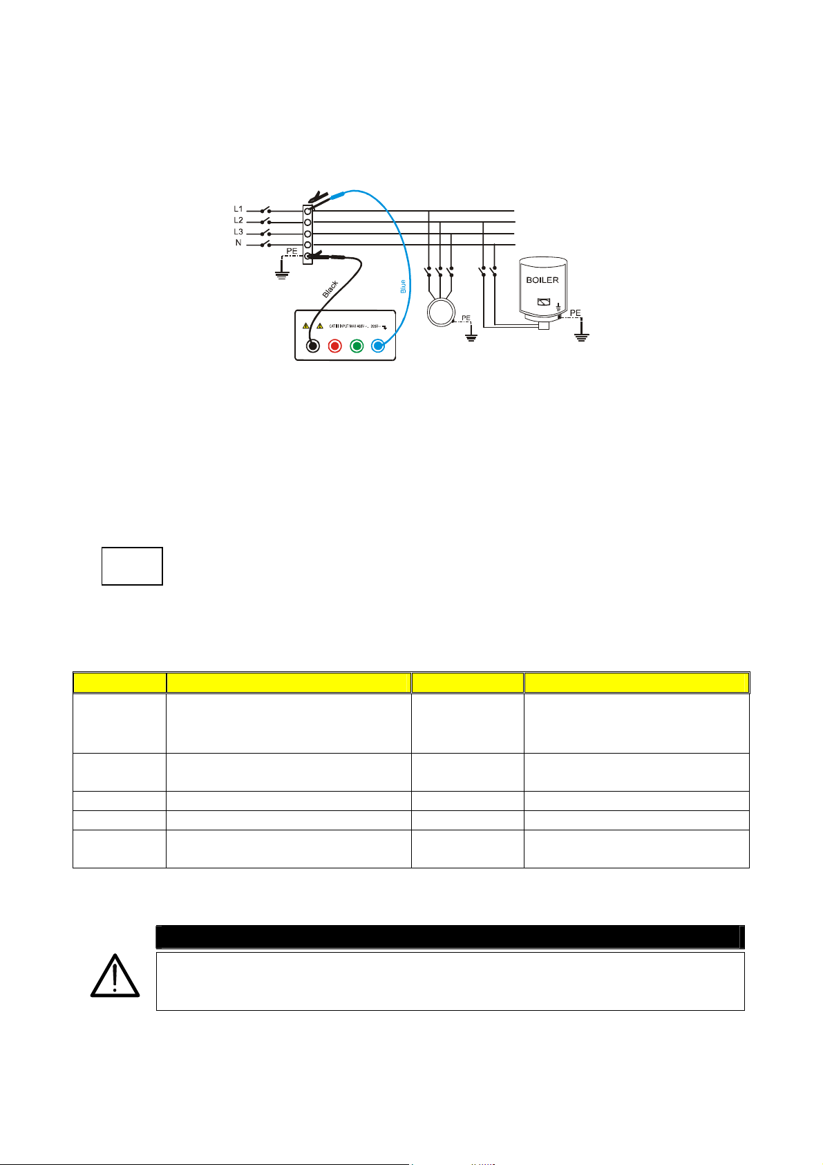
11.1. LOWΩ: CONTINUITY MEASUREMENT ON PROTECTIVE CONDUCTORS
PURPOSE OF THE TEST
Check the continuity of:
a) Protective conductors (PE), main equalizing potential conductors (EQP), secondary
equalizing potential conductors (EQS) in TT and TN-S systems.
b) Neutral conductors having functions of protective conductors (PEN) in TN-C system.
NOTE: This test is to be preceded by a visual check verifying the existence of yellow-
green protective and equalizing potential conductors as well as compliance of the
sections used with the standards’ requirements.
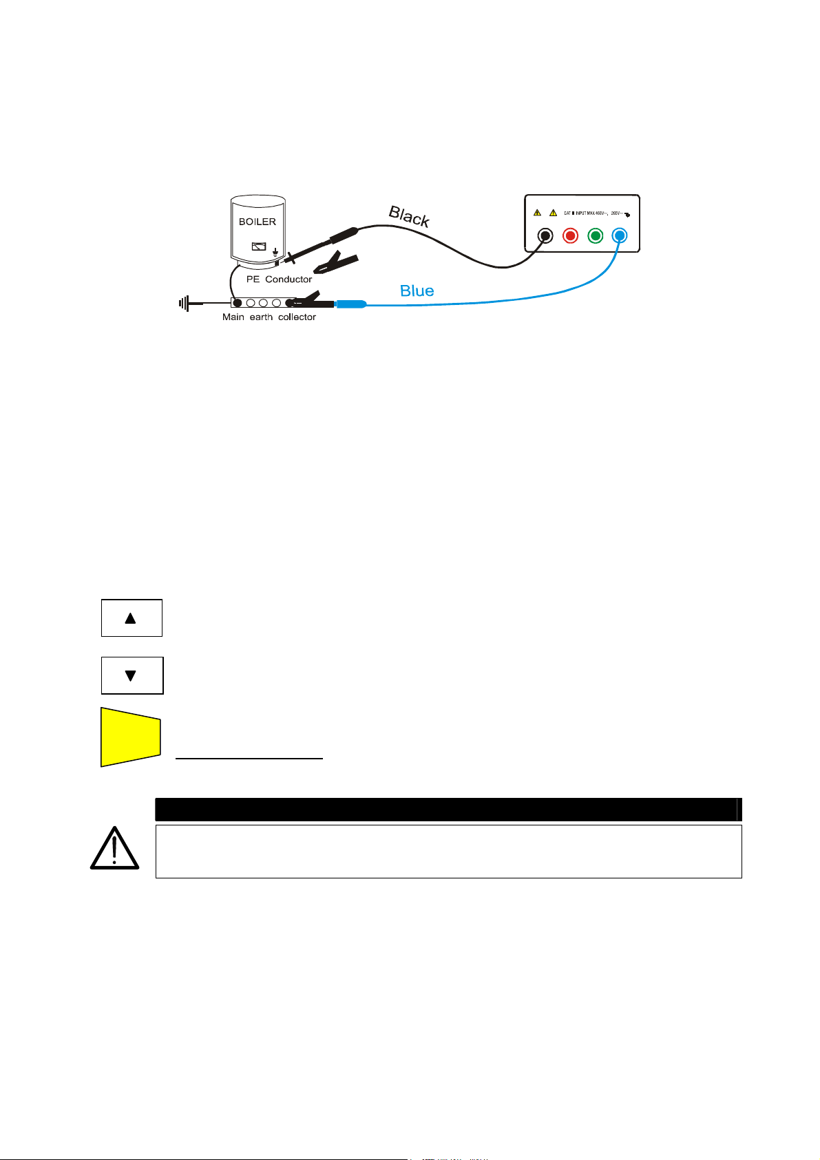
INSTALLATION PARTS TO BE CHECKED
Connect one of the
test leads to the
protective
conductor of the
FM socket and the
other to the
equalizing potential
node of the earth
installation.
Connect one of the
test leads to the
external mass (in
this case the water
pipe) and the other
to the earth
installation using
for example the
protective
conductor of the
closest FM socket.
Examples for continuity measurement on conductors
Page 56

Check the continuity among:
a) Earth poles of all the plugs and earth collector or node.
b) Earth terminals of class I instruments (Boiler etc.) and earth collector or node.
c) Main external masses (water, gas pipes etc.) and earth collector or node.
d) Auxiliary external masses to the earth terminal.
ALLOWABLE VALUES
The standards CEI 64-8/6 do not give any indication of the maximum resistance values in
order to be able to declare a positive outcome of a continuity test.
The standard CEI 64-8/6 simply requires that the instrument in use warns the operator if
the test was not carried out with a current of at least 0.2 A and an open circuit voltage
ranging from 4 V to 24 V.
The resistance values can be calculated according to the sections and lengths of the
conductors under test. If the instrument detects values of some resistance the test can be
considered as passed.
11.2. INSULATION RESISTANCE MEASUREMENT OF THE ELECTRICAL
INSTALLATIONS (250VDC, 500VDC, 1000VDC)
PURPOSE OF THE TEST
Check that the insulation resistance of the installation complies with the requirements of
standards CEI 64-8/6.
NOTE: This test is to be performed on an open circuit with all loads disconnected
.
INSTALLATION PARTS TO BE CHECKED
a) Between each active conductor and the earth (the neutral conductor is considered an
active conductor except in the case of TN-C systems where it is considered part of the
earth (PEN). During this measurement all active conductors can
be connected to each
other, in case the measurement result does not fall within the standard limits the test is
to be repeated for each single conductor.
b) Among active conductors
insulation among the active conductors when this is possible (ATTENTION)
. The standard CEI 64-8/6 recommends checking the
.
ALLOWABLE VALUES
The values of test voltage and minimum insulation resistance are reported in the following
table (CEI64-8/6 Tab. 61A):
Rated circuit voltage (V) Test voltage (V)
SELV and PELV* 250
Up to 500 V included, except for the
above circuits.
500
Over 500 V 1000
Insulation resistance (MΩ)
≥0.250
≥0.500
≥1.000
* In the new standards the terms SELV and PELV replace the old definitions "safety low
voltage" or "functional".
Page 57

Test voltage values and relative limit values for the most common kinds of test.
Page 58

11.3. MEASUREMENT OF FLOOR INSULATION RESISTANCE IN MEDICAL ROOMS
PURPOSE OF THE TEST
Check that the floor is made of material whose insulation resistance complies with the
requirements of the standards CEI 64-4 (3.05.03).
INSTALLATION PARTS TO BE CHECKED
The test shall be performed between:
a) Two electrodes whose distance to each other shall be one meter.
b) One electrode on the floor and the equalizing potential node.
EQUALIZING POTENTIAL NODE
T
Test a):
Connect one test lead of the instrument
to the equalising potential node and the
other to one of the electrodes placed
on the floor at a distance higher than
one meter away from earthed objects
.
TEST LEADS
T
Test b ):
Connect the instrument test leads to
the electrodes placed on the floor at
a reciprocal distance of one meter
.
Measurements of floor insulation resistance in medical rooms
The electrodes shall consist of a plate having a surface of 20 cm2, weight equal to approx.
1 Kg (2.2 lb), and a moisture absorbent paper (or thin cotton cloth) with the same surface
placed between the metal plate and the floor.
The insulation resistance is represented, both for the measurements indicated in "a" and
for the measurements indicated in "b", by the average of 5 or more tests performed in
different positions at a distance greater than 1 m away from earthed objects.
ALLOWABLE VALUES
The maximum values of the calculated resistance are the following:
- 1 MΩ for measurements performed on a new floor.
- 100 MΩ for the periodic tests performed after the first year from the floor construction
and for the periodic checks every 4 years.
All the values shall be registered on a protocol of the initial tests (64-4 5.1.02).
Page 59

11.4. CHECK OF THE CIRCUIT SEPARATION
PURPOSE OF THE TEST
The test, to be performed in case the protection is realized through separation (64-8/6
612.4, SELV or PELV or electrical separation), shall check that the insulation resistance
measured according to the indications below (depending on the separation type) complies
with the limits reported in the table relative to the insulation measurements.
INSTALLATION PARTS TO BE CHECKED
• SELV system (Safety Extra Low Voltage):
9 Measure the resistance between the active parts of the circuit under test (separate)
and the active parts of the other circuits.
9 Measure the resistance between the active parts of the circuit under test (separate)
and the earth.
The resistance shall not be lower than 0.25MΩ with a test voltage of 250VDC.
• PELV system (Protective Extra Low Voltage):
9 Measure the resistance between the active parts of the circuit under test (separate)
and the active parts of the other circuits.
The resistance shall not be lower than 0.25MΩ with a test voltage of 250VDC.
• Electrical separation:
9 Measure the resistance between the active parts of the circuit under test (separate)
and the active parts of the other circuits.
9 Measure the resistance between the active parts of the circuit under test (separate)
and the earth.
The resistance shall not be lower than 0.5MΩ with a test voltage of 500VDC and 1MΩ with
a test voltage of 1000VDC.
ALLOWABLE VALUES
The test result is positive when the insulation resistance indicates values greater or equal
to those indicated in the table reported in the section relative to insulation tests.
Please note that:
A SELV system is a system of category zero or very low safety voltage featured by:
independent source (ex. batteries, small generator) or safety (ex. safety transformer)
power supply, protection separation to other electrical systems (double or reinforced
insulation or a metal screen connected to the earth) and no earthed points (insulated from
the earth).
A PELV system is a system of category zero or very low safety voltage featured by:
independent source (ex. batteries, small generator) or safety (ex. safety transformer)
power supply, protection separation to other electrical systems (double or reinforced
insulation or a metal screen connected to the earth) and there are earthed points (not
insulated from the earth).
Page 60

A system with Electrical separation is featured by: insulation transformer or autonomous
source with equivalent features (ex. generator) power supply, protection separation to
other electrical systems (insulation not lower than that of the insulation transformer) and
protection separation to the earth (insulation not lower than that of the insulation.
Page 61

EXAMPLE OF CHECKING THE SEPARATION AMONG ELECTRICAL CIRCUITS
Insulation or safety transformer making
the separation among the circuits.
TEST AMONG THE ACTIVE PARTS
Connect a test lead of the instrument
to one of the two conductors of the
separate circuit and the other to one of
the conductors of a no separate circuit.
Between active parts of
the separated circuit...
...and among those
others circuits
EQUALIZING POTENTIA L NODE
TEST BETWEEN ACTIVE
PARTS AND THE EARTH
Connect a test lead of the
instrument to one of the two
conductors of the separate
circuit and the other to the
equalising potential node.
This test is to be effected
only for SELV circuits or
with electrical separation.
…and Earth installation
Measurement of separation among the installation circuits
Page 62

11.5. EARTH RESISTANCE MEASUREMENT, VOLTAMPEROMETRIC METHOD
Method for small earth plant
Let a current circulate between the earth rod and a current probe positioned at a distance
from the earth equipment outline corresponding to five times the diagonal of the area
delimiting the earth equipment. Positions the voltage probe halfway between the earth rod
and the current probe, then measure the voltage between the two.
Use several rods in parallel and moisten
the surrounding ground if the instrument
does not manage to supply the current
necessary to perform the test because
of an high earth resistance.
Re d
Green
Bl u e
Bl a c k
Earth resistance measurement for small earth plant
Method for big earth plant
Also this procedure is based on the voltamperometric method, but it’s mainly used when
it’s difficult to position the auxiliary current rod at a distance corresponding to fivefold the
diagonal of the area of the earth equipment. Position the current probe at a distance equal
to the diagonal of the area of the earth equipment. To make sure that the voltage probe is
positioned outside the area affected by the rod under test, take more measurements, first
positioning the voltage probe halfway between the rod and the current probe, and then
moving the probe both towards the earth rod and towards the current probe.
Page 63

Use several rods in parallel and moisten
the surrounding ground if the instrument
does not manage to supply the current
necessary to perform the test because
of an high earth resistance.
Re d
Green
Bl a c k
Earth resistance measurement for big earth plant
Bl u e
Page 64

11.6. EARTH RESISTIVITY MEASUREMENT
PURPOSE OF THE TEST
This test measures the resistivity value of the ground in order to define the type of rods to
be used.
EQUIPMENT PARTS TO BE TESTED
For the resistivity test admissible values do not exist. The various values measured by
positioning the rods at increasing distances “a” must be specified in a graph. According to
the resulting curve, suitable rods will be chosen. Metal parts buried in the ground, such as
pipes, cables or other rods, can affect the test results. In case of doubt take a second
measurement positioning the rods at an equal distance "a", but rotating their axis by 90°.
Black
R
Green
d
e
2
2° Measurement:
compared to the previous measurement
the rods are rotated by
90°.
90°
a
a
e
u
l
B
a
aaa
R
e
d
G
r
e
e
n
k
B
l
u
e
c
a
l
B
The resistivity value is calculated with the following formula: ρ=2πaR
where: ρ= specific resistivity of the ground
a= distance between the rods (m)
R= resistance measured by the instrument (Ω)
This measuring method defines the specific resistance up to the depth corresponding to
the approximate distance “a” between the rods. If you increase the distance “a” you can
reach deeper ground layers and check the ground homogeneity. After several ρ
measurements, at growing distances “a”, you can trace a profile like the following ones,
according to which the most suitable rod is chosen.
Page 65

)
m
Ω
(
E
ρ
d
n
u
o
r
g
e
h
t
f
o
y
t
i
v
i
t
s
i
s
e
r
c
i
f
i
1
2
3
c
e
p
S
Distance between the rods a(m)
APPROXIMATE EVALUATION OF INTENTIONAL RODS CONTRIBUTION (64-12 2.4.1)
The resistance of a rod Rd can be calculated with the following formulas (ρ = medium
resistivity of the ground).
a) Resistance of a vertical rod
L= length of the element touching the ground
b) Resistance of a horizontal rod
Rd = 2ρ / L
L= length of the element touching the ground
c) Resistance of linked elements
The resistance of a complex system with more elements in parallel is always greater
than the resistance that could result from a simple calculation of elements in parallel,
especially if those elements are close and therefore interactive. For this reason, in
case of a linked system the following formula is quicker and more effective than the
calculation of the single horizontal and vertical elements:
r= radius of the circle which circumscribes the link
Rd = ρ / L
Rd = ρ / 4r
Curve 1: as ρ decreases only in
depth, it’s possible to use only a
rod in depth.
Curve 2: as ρ decreases only
until the depth A, it’s not useful to
increase the depth of the rod
beyond A.
Curve 3: even at a superior
depth, ρ does not decrease,
therefore a ring rod must be
used.
Page 66

Copyright Amprobe 2003
Manual de Instrucciones
MultiTest 1000
Page 67

Page 68

AMPROBE
MULTITEST1000
Indice:
1. PRECAUCIONES Y MEDIDAS DE SEGURIDAD ......................................................3
1.1. INSTRUCCIONES PRELIMINARES .................................................................................3
1.2. DURANTE EL USO ...........................................................................................................4
1.3. DESPUES DEL USO.........................................................................................................4
2. DESCRIPCION GENERAL.........................................................................................5
2.1. FUNCIONES......................................................................................................................5
2.2. DESCRIPCION DEL INSTRUMENTO ..............................................................................6
3. PREPARACION PARA EL USO ................................................................................7
3.1. CONTROLES INICIALES ..................................................................................................7
3.2. ALIMENTACION DEL INSTRUMENTO ............................................................................7
3.3. CALIBRACION ..................................................................................................................7
3.4. ALMACENAMIENTO .........................................................................................................7
3.5. SELECCIÓN DE IDIOMA Y UNIDAD DE MEDIDA ...........................................................8
4. DESCRIPCION DEL CONMUTADOR DE FUNCIONES ............................................9
4.1. LOWΩ: PRUEBA CONTINUIDAD DE CONDUCTORES DE PROTEC Y EQUIP. ...........9
4.1.1. MODALIDAD "CAL".......................................................................................................................10
4.1.2. P
4.1.3. S
ROCEDIMIENTO DE MEDIDA PARA LA CONTINUIDAD DE LOS CONDUCTORES EQUIPOTENCIALES
MODALIDAD
ITUACIONES ANOMALAS EN LAS PRUEBAS "AUTO", "R+TIMER", "R-TIMER" ..............................14
"AUTO", "R+TIMER", "R-TIMER" ...........................................................................12
4.2. MΩ: MEDIDA DE LA RESISTENCIA DE AISLAMIENTO CON TENSION DE PRUEBA
DE 50V, 100V, 250V, 500V o 1000V
4.2.1. PROCEDIMIENTO DE PRUEBA DE AISLAMIENTO EN TODAS LAS MODALIDADES ...................................16
4.2.2. S
4.3.
4.3.1. MODALIDAD " "........................................................................................................................22
4.3.2. S
ITUACIONES ANOMALAS EN LAS PRUEBAS "MAN" Y "TIMER" .......................................................20
: INDICADOR DE SECUENCIA DE FASES...............................................................21
ITUACIONES ANOMALAS EN LAS PRUEBAS DE SECUENCIA DE FASES ..............................................23
.........................................................................15
4.4. EARTH ρ: MEDIDA DE LA RESISTENCIA Y RESISTIVIDAD DE TERRENO ...............25
4.4.1. PROCEDIMIENTO DE MEDIDA PARA LA MODALIDAD DE PRUEBA "2P".................................................26
4.4.2. P
4.4.3. P
ROCEDIMIENTO DE MEDIDA PARA LA MODALIDAD DE PRUEBA "3P".................................................29
ROCEDIMIENTO DE MEDIDA PARA LA MODALIDAD DE PRUEBA "ρ" ...................................................31
4.5. SITUACIONES ANOMALAS MODALIDAD EARTH ρ .....................................................33
5. COMO GUARDAR, RECUPERAR Y BORRAR DATOS GUARDADOS EN
MEMORIA.................................................................................................................35
5.1. TECLA GUARDAR: "SAVE" ............................................................................................35
5.2. TECLA RECUPERAR: "RCL"..........................................................................................36
5.3. TECLA BORRAR: "CLR" .................................................................................................37
6. RESETEADO DEL INSTRUMENTO Y DE LOS PARÁMETROS ESTANDAR........38
6.1. PROCEDIMIENTO DE RESETEADO .............................................................................38
6.2. PARAMETROS ESTANDAR ...........................................................................................38
7. CONEXIÓN DEL INSTRUMENTO A UN PC ............................................................39
8. MANTENIMIENTO ....................................................................................................40
8.1. GENERALIDADES ..........................................................................................................40
8.2. CAMBIO DE BATERIAS..................................................................................................40
8.3. LIMPIEZA DEL INSTRUMENTO .....................................................................................40
9. ESPECIFICACIONES TECNICAS............................................................................41
9.1. CARACTERISTICAS TECNICAS....................................................................................41
9.1.1. NORMAS DE SEGURIDAD ......................................................................................................42
9.1.2. CARACTERISTICAS GENERALES..........................................................................................42
9.2. AMBIENTE ......................................................................................................................43
9.2.1. CONDICIONES AMBIENTALES DE USO .............................................................................................43
9.2.2. EMC...........................................................................................................................................43
9.3. ACCESORIOS.................................................................................................................43
10. ASISTENCIA.............................................................................................................44
10.1. CONDICIONES DE GARANTIA ......................................................................................44
11. FICHAS PRACTICAS PARA LAS VERIFICACIONES ELECTRICAS.....................45
11.1. LOWΩ: MEDIDA CONTINUIDAD DE CONDUCTORES DE PROTECCION..................45
EN - 1
Page 69

AMPROBE
11.2. MEDIDA DE LA RESISTENCIA DE AISLAMIENTO DE INSTALACIÓN ELECTRICA
(250VDC, 500VDC, 1000VDC)........................................................................................46
11.3. MEDIDA DE LA RESISTENCIA DE AISLAMIENTO DE SUELOS EN LOCALES DE
USO MEDICO..................................................................................................................48
11.4. VERIFICACION DE LA SEPARACIÓN DE LOS CIRCUITOS ........................................49
11.5. MEDIDA DE LA RESISTENCIA DE TIERRA, METODO VOLTIAMPERIMETRICO.......52
11.6. MEDIDA DE LA RESISTIVIDAD DEL TERRENO...........................................................53
MULTITEST1000
Release SP 1.00 del 01/05/2003
EN - 2
Page 70

AMPROBE
MULTITEST1000
1. PRECAUCIONES Y MEDIDAS DE SEGURIDAD
El instrumento ha sido proyectado en conformidad a las directivas EN61557 y EN 61010-1
relativas a los instrumentos de medida electrónicos.
ATENCIÓN
Para su seguridad y para evitar dañar al instrumento, Le rogamos que siga
los procedimientos descritos en el presente manual y lea con particular
atención todas las notas precedidas por el símbolo ..
Antes y durante la ejecución de las medidas fíjese atentamente en las siguientes
indicaciones:
) No efectúe medidas de tensión o corriente en ambientes húmedos.
) No efectúe medidas en presencia de gas, materiales explosivos o combustibles
) Evite el contacto con el circuito en examen si se está efectuando medidas.
) Evite el contacto con partes metálicas desnudas, con terminales de medida inutilizados,
circuitos, etc.
) No efectúe alguna medida si existe alguna anomalía en el instrumento como,
deformaciones, roturas, pérdidas de sustancias, ausencia de símbolos en el
visualizador, etc.
) Preste particular atención cuando esté efectuando medidas de tensión superior a 25V en
ambientes especiales (obras, piscinas,..) y 50V en ambientes ordinarios en cuanto se
encuentre en presencia de riesgo de choques eléctricos.
En el presente manual son utilizados los siguientes símbolos:
Atención: fíjese en las instrucciones reflejadas en el manual; un uso impropio
podría causar daños al instrumento y a sus componentes.
Tensión o Corriente CA.
Tensión o Corriente pulsante unidireccional.
Conmutador del Instrumento.
1.1. INSTRUCCIONES PRELIMINARES
) Este instrumento ha sido proyectado para su uso en ambientes de polución 2
) Puede ser utilizado para comprobaciones en instalaciones eléctricas con categoría de
sobretensión 265V (a tierra).
SP - 3
Page 71

AMPROBE
) Le sugerimos que siga las reglas de seguridad orientadas a:
9 Protegerle contra corrientes peligrosas.
9 Proteja el instrumento contra un uso erróneo.
) Sólo los accesorios incluidos con el equipo garantizan las normas de seguridad.
Deben estar en buenas condiciones y si fuese necesario, sustituirlos por los modelos
originales.
) No efectúe medidas en circuitos que superen los límites de corriente y tensión
especificados.
) No efectúe medidas en condiciones ambientales fuera de los límites indicados en el
presente manual.
) Controle que las baterías estén insertadas correctamente.
) Antes de conectar las puntas de prueba al circuito en examen, controle que el
conmutador esté posicionado correctamente.
) Controle que el visualizador y el conmutador indiquen la misma función.
1.2. DURANTE EL USO
Le rogamos que lea atentamente las recomendaciones y las instrucciones siguientes:
MULTITEST1000
ATENCIÓN
La falta de observación de las Advertencias y/o Instrucciones puede dañar el
instrumento y/o sus componentes o ser fuente de peligro para el usuario.
) Antes de accionar el conmutador, quite las puntas de prueba del circuito en examen.
) Cuando el instrumento está conectado al circuito en examen no toque nunca cualquier
terminal inutilizado.
) Evite la medida de resistencia en presencia de tensiones externas; aunque el
instrumento está protegido, una tensión excesiva podría causar un mal funcionamiento
del instrumento.
ATENCIÓN
Si durante el uso aparece el símbolo suspenda la prueba y reemplace
las baterías siguiendo el procedimiento descrito en el párrafo. El instrumento
es capaz de mantener los datos guardados aunque las baterías no estén
instaladas.
1.3. DESPUÉS DEL USO
) Cuando las medidas han finalizado, apague el instrumento manteniendo pulsada la
tecla ON/OFF durante algunos segundos.
) Retire las baterías cuando el instrumento este mucho tiempo sin utilizar.
SP - 4
Page 72

AMPROBE
MULTITEST1000
2. DESCRIPCIÓN GENERAL
Le agradecemos que haya escogido un instrumento de nuestro programa de ventas. El
instrumento que acaba de adquirir, si se utiliza según lo descrito en el presente manual, le
garantizará medidas precisas y fiables.
El instrumento está realizado de modo que garantiza la máxima seguridad gracias a un
desarrollo de nueva concepción que asegura el doble aislamiento y el cumplimiento de la
categoría de sobretensión III.
2.1. FUNCIONES
) LOWΩ: Prueba de Continuidad de los Conductores de protección o equipotencial
con Corriente de Prueba superior a 200mA y tensión de vacío
comprendido entre 4V y 24V.
) R
) : Indicación de rotación de secuencia de fases
) EARTH ρ: Medida de la resistencia de tierra y de la resistividad del terreno a través
) RS232: Posición del conmutador para la posición de comunicación RS232.
: Medida de la Resistencia de Aislamiento con Tensión CC de Prueba 50V,
ISO
100V, 250V, 500V o 1000V.
de picas auxiliares.
SP - 5
Page 73

AMPROBE
2.2. DESCRIPCION DEL INSTRUMENTO
MULTITEST1000
LEYENDA:
1
2
3
FUNC
U
n
DIST
1. Visualizador
2. Teclas Función
3. Conmutador rotatorio
∆
Un/I
n
FUNC
S V UL W
DIST
START
STOP
DISP
CLR
RCL
SAVE
ESC
) Tecla FUNCION para seleccionar la modalidad de medida.
) Tecla Un / DIST para seleccionar la tensión nominal o distancia
dependiendo de la medida seleccionada.
START
STOP
DISP
CLR
RCL
ESC
) Tecla para aumentar el intervalo de duración de la prueba o para
visualizar los resultados de las medidas memorizadas.
) Tecla para disminuir el intervalo de duración de la prueba o para
visualizar los resultados de las medidas memorizadas.
) Tecla ON/OFF. Manténgala pulsada durante unos segundos para apagar
el instrumento, suéltela cuando oiga la indicación acústica
) Esta tecla Inicia (y Detiene) las medidas.
) DISPLAY tecla para hojear los resultados.
) CLEAR tecla para cancelar los resultados.
) RECALL/ESCAPE tecla visualizar las pruebas memorizadas (RCL)
Tecla para abandonar la función o modalidad (ESC).
SAVE
) Esta tecla permite la memorización de los resultados visualizados.
SP - 6
Page 74

AMPROBE
MULTITEST1000
3. PREPARACIÓN PARA EL USO
3.1. CONTROLES INICIALES
El instrumento, antes de ser expedido, ha sido controlado desde el punto de vista eléctrico
y mecánico.
Han sido tomadas todas las precauciones posibles con el fin que el instrumento pueda ser
entregado sin ningún daño.
De todas formas se aconseja controlar exhaustivamente el instrumento para comprobar
que no haya sufrido daños durante el transporte. Si se detecta alguna anomalía contacte
inmediatamente con la sociedad Amprobe.
Se aconseja además controlar que el embalaje contenga todas las partes indicadas en el
párrafo 14.5. En caso de discrepancias contacte con el distribuidor.
En caso de que fuera necesario devolver el instrumento, se ruega seguir las instrucciones
indicadas en el párrafo 10.
3.2. ALIMENTACIÓN DEL INSTRUMENTO
El instrumento se alimenta mediante seis baterías referencia AA no incluidas en el
embalaje. Para la colocación de las baterías siga las indicaciones del párrafo 8.2.
Cuando las baterías estén descargadas aparece el símbolo. . Para sustituirlas siga las
instrucciones indicadas al párrafo 8.2.
3.3. CALIBRACIÓN
El instrumento respeta las características técnicas reflejadas en el presente manual. Las
prestaciones del instrumento están garantizadas durante un año desde la fecha de
adquisición.
3.4. ALMACENAMIENTO
Para garantizar medidas precisas, después de un largo período de almacenamiento en
condiciones ambientales extremas, espere que el instrumento vuelva a las condiciones
normales (ver especificaciones ambientales listadas en el párrafo 9.2.1.)
SP - 7
Page 75

AMPROBE
3.5. SELECCIÓN DE IDIOMA Y UNIDAD DE MEDIDA
Es posible configurar el idioma y la unidad de medida (en resistividad de terreno)
siguiendo el procedimiento:
1. Mientras mantiene la tecla FUNC pulsada, encienda el instrumento ON (la posición del
conmutador no es relevante.
2.
)
El instrumento visualizará la siguiente
pantalla.
MULTITEST1000
le m
3.
)
Pulse la tecla SAVE para confirmar la
elección. El instrumento visualizará la
siguiente pantalla.
)
Pulsando la tecla ESC saldrá del menú
sin confirmar ningún cambio.
le m
OK
SP - 8
Page 76

AMPROBE
MULTITEST1000
4. DESCRIPCIÓN DEL CONMUTADOR DE FUNCIONES
4.1. LOWΩ: PRUEBA DE CONTINUIDAD DE LOS CONDUCTORES DE
PROTECCIÓN Y EQUIPOTENCIALIDAD
Las pruebas se realizan a una corriente de prueba superior a 200 mA y una tensión de
cortocircuito desde 4 a 24V DC de acuerdo a EN 61557-2 y VDE 0413 parte 4.
ATENCIÓN
Antes de realizar la prueba de Continuidad asegurarse que no haya tensión al
final del conductor que debemos analizar.
Gire el conmutador en posición LOWΩ.
FUNC
Encienda el instrumento.
Con la tecla FUNC es posible seleccionar una de las siguientes modalidades
de medida:
) Modalidad “AUTO” (el instrumento efectúa dos medidas de polaridad R+
y R-, polaridad y visualiza el valor medio R
para la prueba de continuidad.
) Modalidad “R + TIMER” (medida con polaridad positiva y con la
posibilidad de programar el tiempo de duración de la prueba). En este
caso el usuario puede programar el tiempo de medida suficientemente
largo para poder mover los conductores de protección mientras el
instrumento está ejecutando la prueba y poder localizar una eventual
conexión errónea.
) Modalidad “R - TIMER” (medida con polaridad negativa y con la
posibilidad de programar el tiempo de duración de la prueba). En este
caso el usuario puede programar el tiempo de medida suficientemente
largo para poder mover los conductores de protección mientras el
instrumento está ejecutando la prueba y poder localizar una eventual
conexión errónea.
) Modalidad “CAL” (compensación de la resistencia de los cables
utilizados para la medida).
). Modalidad aconsejada
avg
Nota La prueba de continuidad se realiza inyectando una corriente superior a 200mA
en el caso en el que la resistencia no sea superior a 5Ω (comprendida la
resistencia de los cables de medida memorizada como offset en el instrumento
después de haber realizado el procedimiento de calibración). Para valores de
resistencia superiores el instrumento realiza la prueba con una corriente inferior a
200mA.
SP - 9
Page 77

AMPROBE
pag
MULTITEST1000
4.1.1. Modalidad "CAL"
1. Seleccione la modalidad CAL usando la tecla FUNC.
2. Inserte el cable Negro y el cable Azul en los respectivos terminales de entrada T1 y T4
del instrumento
T2 T3
T1
T4
Conexión de los terminales del instrumento durante el procedimiento de calibración
3. Si, para realizar una medida, la longitud de los cables en dotación fuera insuficiente
prolongar el cable azul.
4. Conecte los cocodrilos a los terminales de los cables.
5. Cortocircuitar las terminaciones de los cables de medida teniendo cuidado que las partes
conductoras de los cocodrilos realicen un buen contacto reciproco (ver figura anterior).
START
6. Pulse la tecla START/STOP. El instrumento efectuará la calibración.
STOP
)
Al término de la prueba
CAL LOWΩ
el valor medido está
memorizado en el
0.00Ω
instrumento y lo
utilizará como
COMPENSACIÓN (es
decir será anulado en
203 mA
todas las medidas de
continuidad que se
realicen) hasta una
nueva calibración.
La pantalla visualizará en 2 segundos al
mismo tiempo que el instrumento emite una
doble señal acústica (señalando la
calibración) y visualiza la pantalla estándar
Mensaje: CAL:
significa que el
instrumento
estácalibrado;
este símbolo será
visualizado en
sucesivas
medidas aunque
el instrumento se
a
a.
Corriente
aplicada por el
instrumento
durante el
procedimiento de
calibración.
relativa a la prueba LOWΩ modo AUTO.
Nota: El instrumento realiza la calibración de los cables de medida sólo si la resistencia
de estos últimos es inferior a 5Ω.
SP - 10
Page 78

AMPROBE
r
PUNTAS DE PRUEBA Asegurarse siempre, antes de cada medida, que
la calibración se refiera a los cables utilizados en
el momento. En una medida de continuidad si el
valor de resistencia depurado de la calibración (es
decir valor de la resistencia menos el valor del
offset de la calibración) resultase negativo, se
visualizaría el símbolo . Probablemente la
calibración memorizada en el instrumento no se
refiere a los cables en uso, por lo tanto debe ser
realizada una nueva calibración. (referenciado a la
5ª pantalla del párrafo 4.1.3.).
MULTITEST1000
ATENCIÓN
No desconectar nunca los terminales de los puntos de medida cuando el
instrumento visualiza el mensaje "MEASURING"
4.1.1.1. Procedimiento para borrar los parámetros de calibración del símbolo cal
Para borrar los parámetros de calibración (y
el símbolo CAL de la pantalla) hace falta
efectuar un procedimiento de calibración
con una resistencia en las puntas de
prueba superior a 5Ω (por ejemplo con las
puntas de prueba abiertas). Cuando se
efectúa una cancelación se visualizará la
primera pantalla (ver derecha), luego
aparecerá la pantalla siguiente.
La pantalla se visualizará en 2 segundos,
transcurrido este tiempo, el instrumento
emite una señal acústica prolongada y
luego aparecerá en pantalla la prueba LOW
Ω modo AUTO.
LOWΩ
>5 Ω
cal
Measuring
LOWΩ
es
cal
Mensaje >5Ω:
significa que el
instrumento ha leido
una resistencia
superior a 5Ω po
tanto procederá a
Resetear.
Mensaje rES:
significa que el
instrumento ha
ejecutado la
cancelación
(RESET) de los
parámetros de
calibración
SP - 11
Page 79

AMPROBE
MULTITEST1000
4.1.2. Procedimiento de medida para la continuidad de los conductores
equipotenciales modalidad AUTO, R+TIMER, R-TIMER
1. Seleccione con la tecla FUNC la modalidad que interese.
2. Inserte el cable Negro y el Azul en los correspondientes terminales de entrada T1 y T4
del instrumento
T2 T3
T1
T4
Conexión de las terminales del instrumento prueba LOW Ω.
3. Si para efectuar la medida es necesario alargar la longitud de los cables incluidos es
suficiente con alargar el cable azul.
4. Conecte los cocodrilos en los terminales de los cables.
5. Cortocircuite los terminales de los cables de medida con la precaución que hagan buen
contacto entre ellos. Presione la tecla GO. Si el instrumento visualiza un valor de
resistencia superior a 0,00 repita la calibración del instrumento (ver párrafo 4.1.1).
6. Conecte los terminales del instrumento al conductor que desee comprobar (ver figura
anterior).
7. Si ha sido seleccionada la modalidad R+TIMER o R- TIMER utilice las siguientes
teclas para elegir el tiempo de duración de la prueba
Presione esta tecla para aumentar el tiempo de duración de la prueba
(Tmax=15 segundos).
START
STOP
Presione esta tecla para disminuir el tiempo de duración de la prueba
(Tmin=1 segundos).
8. Pulse la tecla START/STOP. El instrumento realizará la medida.
En modalidad R+/ R- púlsela tecla START/STOP de nuevo si se quiere
detener la prueba.
ATENCIÓN
No desconectar nunca los terminales de los puntos de medida cuando el
instrumento visualiza el mensaje "MEASURING"
SP - 12
Page 80

AMPROBE
4.1.2.1. Mode "AUTO"
MULTITEST1000
)
Al término de la prueba, en el caso en que
el valor medio de la resistencia Ravg
resulta inferior a 5 Ω, el instrumento
emite una doble señal acústica que
señala el resultado positivo de la prueba
y visualizará los siguientes valores
obtenidos.
SAVE
4.1.2.2. Modalidad "R+TIMER" o “R-TIMER"
)
Al término de la prueba, en el caso de
detectar una resistencia R+ Timer o R -
Timer inferior a 5 Ω, el instrumento, al
finalizar la prueba, emite una doble
señal acústica que señala el resultado
positivo de la prueba y visualizará los
siguientes valores obtenidos.
Los símbolos R+ or R- son visualizados
GUARDAR: La prueba se memoriza pulsando dos veces la tecla SAVE
(según lo descrito en el párrafo 5.1).
CAL LOWΩ
1.07 Ω
219 mA
AUTO
CAL LOWΩ
1.08 Ω
219 mA 5 s
R+
R-
TIMER
Valor medio de la
resistencia Ravg
Valor medio de la
corriente Iavg de
prueba
Duración del
tiempo de la
prueba
Valor de la
corriente I+ o I-
de prueba
SAVE
GUARDAR: La prueba se memoriza pulsando dos veces la tecla SAVE
(según lo descrito en el párrafo 5.1).
SP - 13
Page 81

AMPROBE
A
V
Ω
r
r
MULTITEST1000
4.1.3. Situaciones anómalas en las que se puede encontrar durante las pruebas
AUTO, R+TIMER, R- TIMER
)
En el caso en que haya detectado una
Ravg o R+ o R - superior o igual a 5
Ω pero inferior a 99,9 Ω, el
instrumento, al finalizar la prueba,
emite una señal acústica prolongada
y visualiza los valores obtenidos.
ATENCION: valor de R
)
En modalidad AUTO, si es detectada
superior a 5
avg
una Ravg o R+ o R - superior a 99,9
Ω, el instrumento, al finalizar la prueba,
emite una señal acústica prolongada
y visualizará los siguientes valores
obtenidos
ATENCION: valor de R
también alto.
)
En el caso en que haya sido
o R+ o R- es
avg
seleccionado R+ TIMER o R- TIMER y
haya sido detectada una R+ o R -
superior a 99,9 Ω, el instrumento, al
finalizar la prueba, emite una señal
acústica prolongada y visualizará los
siguientes valores obtenidos
CAL LOWΩ
5.75Ω
216mA 5s
AUTO
CAL LOWΩ
>99.9Ω
- - - mA
AUTO
CAL LOWΩ
>99.9Ω
- - - mA 4 s
R+
TIMER
Sólo si ha sido
seleccionada la
modalidad
R+TIMER o RTIMER
Modalidad AUTO
99,9Ω es el valo
máximo medible
del instrumento
en modo LOW Ω
AUTO, R+, R -.
Modalidad AUTO
99.9Ω es el valo
máximo
ATENCION: el
valor de R+ o Res también alto.
)
En el caso que:
R
MEDID
-R
CALIBRACION
< 0Ω el
instrumento visualizará la siguiente
pantalla
ATENCION: R
SAVE
MEDIDA-RCALIBRACION
GUARDAR: La prueba se memoriza pulsando dos veces la tecla SAVE
< 0
(según lo descrito en el párrafo 5.1).
)
Si la tensión presente en los terminales
es superior a 10V, el instrumento no
efectuará la prueba, y visualizará en la
pantalla después de 5 segundos, el
instrumento visualiza la pantalla de la
prueba LOW Ω modalidad AUTO.
SAVE
ESTA PRUEBA NO PUEDE SER MEMORIZADA.
CAL LOWΩ
0.00Ω
219 mA
AUTO
CAL LOWΩ
13
VOL AG
Parpadeando CAL
Modalidad AUTO
ATENCIÓN: la
prueba no ha sido
efectuada
Porque hay
tensión en puntas
de prueba.
SP - 14
Page 82

AMPROBE
4.2. MΩ: MEDIDA DE LA RESISTENCIA DE AISLAMIENTO CON TENSIÓN DE
PRUEBA DE 50V, 100V, 250V, 500V O 1000V
Referente a EN 61557-2 y VDE 0413 parte 1.
MULTITEST1000
ATENCIÓN
Antes de realizar la prueba de aislamiento asegurarse que el circuito en
examen no esté alimentado y que todas las cargas de él derivadas estén
desconectadas.
Gire el selector en posición MΩ.
FUNC
Encienda el instrumento.
La tecla FUNC permite seleccionar una de las siguientes modalidades de
medida (se presenta cíclicamente al presionar la tecla FUNC):
) Modalidad “MAN” (tiempo de prueba mínima de 4 segundos o
determinado por la duración de la presión de la tecla START/STOP).
prueba recomendada.
) Modalidad “TIMER” (duración de la prueba que depende del intervalo
seleccionado (de 10 a 999 segundos)). Esta prueba puede ser ejecutada
en el caso en que sea solicitado un tiempo mínimo de medida.
SP - 15
Page 83

AMPROBE
MULTITEST1000
4.2.1. Procedimiento de prueba de la resistencia de aislamiento en todas las
modalidades
1. Seleccione con la tecla FUNC la modalidad que interese.
2. Inserte el cable Negro y el cable Azul en los correspondientes terminales de entrada
T1 y T4 del instrumento,
M
T2 T3 T4T1
Aislamiento entre Fase y Tierra en una instalación eléctrica.
3. Si para poder realizar la medida es necesario unos cables de medida de mayor longitud,
alargue el cable azul.
4. Conecte los terminales del instrumento al punto donde se desea efectuar la prueba de
Aislamiento habiendo desconectado previamente la alimentación del circuito en
examen y todas las posibles cargas capacitativas (ver figura anterior).
U
5. Seleccione con Un la tensión de prueba adecuada al tipo de prueba
n
DIST
que se quiere efectuar (ver Tabla). Los valores seleccionables son:
• 50V (pruebas para sistemas de telecomunicaciones)
• 100V • 500V
• 250V • 1000V
Normativa Breve Descripción Tensión de
Valores Límite Admitidos
Prueba
> 0.250MΩ
> 0.500MΩ
> 1.0MΩ
> 50kΩ (si V < 500V)
> 100kΩ (si V>500V)
> 230kΩ
> 1MΩ
CEI 64-8/6
CEI 64-8/4
EN60439
EN60204
CEI 64-4
Sistemas SELV o PELV
Sistemas hasta 500V (Instal. Civiles)
Sistemas más de 500V
Aisl. Pav. y paredes Instal. Civiles
Aisl. Pav. y paredes en sistemas más de 500V
Cuadros Eléctricos 230/400V 500VDC
Equipo Eléctrico de las Máquinas 500VDC
Aislamiento pav. en Ambientes Uso Clínico 500VDC
250VDC
500VDC
1000VDC
500VDC
1000VDC
< 1MΩ (si pav. real. de 1 año)
< 100MΩ (si pav. real. de +1 año)
Valores de prueba de tensión y límites máximos relativos para los tipos de prueba más comunes.
SP - 16
Page 84

AMPROBE
Si en el visualizador del instrumento aparece el mensaje “Measuring” el
instrumento está ejecutando la medida. No desconecte nunca las puntas de
prueba durante la medida ya que el circuito en examen podría quedar
cargado a una tensión peligrosa a causa de la capacidad parásita de la
instalación. Cualquier modo de funcionamiento seleccionado en el
instrumento en la parte final de cada prueba inserta una resistencia a las
puntas de prueba de salida para efectuar la descarga de las capacidades
parásitas presentes en el circuito.
MULTITEST1000
ATENCIÓN
SP - 17
Page 85

AMPROBE
4.2.1.1. Modalidad "MAN"
START
6. Pulse la tecla START/STOP.
STOP
El instrumento efectúa la medida con una duración:
9 Mínimo 4 segundos en el caso de pulsar y soltar la tecla.
9 Siempre que la tecla no esté en todos los otros casos.
)
Al término de la prueba, en el caso en
que el valor de la resistencia RISO
resulte inferior a RMAX (que depende
de la tensión aplicada ver siguiente
Tabla 4), el instrumento, emite una
doble señal acústica que señala el
resultado positivo de la prueba y
visualizará los valores obtenidos
1.00MΩ
500 V 20 s
MAN
R
ISO
MULTITEST1000
R
Valor de la
ISO
resistencia de
aislamiento
Duración de la
prueba. En este
caso la tecla
START/STOP ha
sido
presionada
durante 20
segundos
.
Valor de la tensión nominal
seleccionada en la prueba
Modalidad Manual
Tal valor de la medida de resistencia de aislamiento siempre será conforme con los límites
normativos (ver tabla) para comprobar si el sistema es correcto.
SAVE
GUARDAR: La prueba se memoriza pulsando dos veces la tecla SAVE
(según lo descrito en el párrafo 5.1).
SP - 18
Page 86

AMPROBE
p
p
4.2.1.2. Modalidad "TIMER"
6. Use las siguientes teclas para seleccionar la duración de la prueba:
Pulse esta tecla para aumentar la duración de la prueba (Tmax=999
segundos).
Pulse esta tecla para disminuir la duración de la prueba (Tmin=10
segundos).
START
7. Pulse la tecla START/STOP .
STOP
El instrumento efectúa la medida acabando en tiempo programado.
999 segundos Valor máximo de la duración de la prueba.
10 segundos Valor mínimo de la duración de la prueba.
MULTITEST1000
Nota: Pulse una segunda vez la tecla START/STOP GO si se quiere detener la prueba en
curso.
)
Al término de la prueba, en el caso en
que el valor de la resistencia R
resulte inferior a R
(que depende de
MAX
ISO
R
ISO
2.07MΩ
Valor de la
resistencia de
aislamiento
R
ISO.
la tensión aplicada ver siguiente Tabla),
y que la prueba sea realizada al valor
de tensión seleccionado, el
instrumento, emite una doble señal
acústica que señala el resultado
500 V 20s
TIMER
Duración de la
rueba
Modalidad Timer
positivo de la prueba y visualiza los
valores obtenidos.
SAVE
GUARDAR: La prueba se memoriza pulsando dos veces la tecla SAVE
Valor de la tensión nominal seleccionada en la
rueba TIMER
(según lo descrito en el párrafo 5.1).
Nota: El valor máximo de resistencia
R
que el instrumento puede medir en la
MAX
modalidad RISO depende de la tensión nominal seleccionada para la prueba. En
particular tendremos:
Tensión Nominal Seleccionada
para la prueba
50VDC
100VDC
250VDC
500VDC
1000VDC
RMAX = VALOR MÁXIMO DE
RESISTENCIA MEDIDA
99.9MΩ
199.9MΩ
499MΩ
999MΩ
1999MΩ
Valores máximos de resistencia que el instrumento mide en modo RISO en función de la tensión
nominal seleccionada.
SP - 19
Page 87

AMPROBE
A
y
MULTITEST1000
4.2.2. Situaciones anómalas en la que se puede encontrar durante las pruebas
"MAN" & "TIMER"
)
Al término de la prueba, en el caso en
que el valor de la resistencia R
resulte superior a R
(que depende
MAX
ISO
de la tensión aplicada ver anterior Tabla
4), el instrumento, emite una doble
señal acústica que señala el
resultado positivo de la prueba y
visualizará los valores obtenidos.
Máximo valor de resistencia que puede ser medido
(999MΩ es visualizado si la tensión de 500V fue
seleccionada, ver tabla).
>999 MΩ
500 V 20 s
MAN
R
ISO
El símbolo ">"
significa que el
valor de la
resistencia R
ma
or que R
Duración de la
Modalidad
seleccionada MAN
ISO
es
)
En el caso en que haya efectuado la
prueba a una tensión inferior a la
nominal programada, el instrumento,
emite una señal acústica prolongada
y visualizará los valores obtenidos.
ATENCIÓN: la prueba de la resistencia R
sido efectuada a un valor de tensión inferior al
valor de la tensión nominal programada. Situación
que se puede averiguar en caso de bajo
aislamiento o en presencia de tensiones
SAVE
GUARDAR: La prueba se memoriza pulsando dos veces la tecla SAVE
ISO
ha
(según lo descrito en el párrafo 5.1).
)
Si la tensión presente entre los
terminales es mayor de 30V, el
instrumento no efectuará la prueba,
visualizará después de 5 segundos, en
la pantalla como en la prueba R
modalidad seleccionada.
ISO
R
ISO
0.01MΩ
500 V 20 s
MAN
R
ISO
33V
VOL
G
Modalidad
seleccionada MAN
ATENCIÓN: la
prueba no ha sido
efectuada.
Verifique que el
circuito no tenga
presencia de
tensión.
SAVE
ESTE RESULTADO NO SE PUEDE GUARDAR EN MEMORIA.
SP - 20
Page 88

AMPROBE
4.3. : INDICADOR DE SECUENCIA DE FASES
Gire el conmutador en la posición.
MULTITEST1000
Encienda el instrumento.
ATENCIÓN
No desconectar nunca los terminales de los puntos de medida cuando el
instrumento visualiza el mensaje "MEASURING"
SP - 21
Page 89

AMPROBE
MULTITEST1000
4.3.1. Modalidad " "
1. Conecte los tres cables negro, rejo y verde en las correspondientes terminales de entrada
del instrumento T1, T2, T3. Inserte los extremos de los cables libres en los cocodrilos.
L1
L2
L3
N
T2 T3
T1
T4
Conexión del instrumento para la indicación del sentido cíclico de las fases L1= cable
negro, L2= cable azul, L3= cable verde
2. Conecte los cocodrilos a las tres fases del sistema en examen. El instrumento
visualizará una pantalla del tipo: (después de pulsar la tecla START/STOP):
Valor de la tensión entre Fase1 y Fase2.
386 V
Valor de la tensión entre Fase3 y Fase1
388V 388V
Valor de la tensión entre Fase2 y Fase3
START
3. Pulse la tecla START/STOP para iniciar la prueba de la secuencia de fases,
STOP
)
El instrumento al fin de la prueba
visualiza los valores en el caso de
sentido cíclico correcto., el cable
negro es conectado a la fase1=L1, el
cable azul a la fase2=L2 y el cable
verde a la fase3=L3.
)
El instrumento al fin de la prueba
visualiza los valores en el caso de
sentido cíclico incorrecto
una de las siguientes pantalla serán visualizadas:
123
213
Mensaje 123:
significa que el
sentido cíclico es
correcto
Mensaje 213:
significa que el
sentido cíclico es
incorrecto
SAVE
ATENCIÓN
No desconectar nunca los terminales de los puntos de medida cuando el
instrumento visualiza el mensaje "MEASURING"
GUARDAR: La prueba se memoriza pulsando dos veces la tecla SAVE
(según lo descrito en el párrafo 5.1).
SP - 22
Page 90

AMPROBE
A
j
4.3.2. Situaciones anómalas que se puede encontrar durante las pruebas de
Sentido Cíclico de las Fases
MULTITEST1000
)
En el caso en que el instrumento
detecte al menos una de las tensiones
presentes entre dos de las fases en
examen sea inferior a 100V, no
efectuará la prueba y visualizará la
siguiente pantalla:
)
Si la tensión de la entrada T1 es muy
baja, cuando pulse START/STOP el
instrumento visualizará la siguiente
pantalla.
)
Si la tensión de la entrada T2 es muy
baja, cuando pulse START/STOP el
instrumento visualizará la siguiente
pantalla.
L
VOL
A
l1
A
G
Mensaje “Lo
VOL tAG”:
el instrumento
detecta una
tensión
demasiado baja
y no puede
efectuar la
prueba.
Mensaje “Att no
L1”: tensión de
fase 1 es muy
baja
Mensaje “Att no
L2”: tensión de
fase 2 es muy
baja
)
Si la tensión de la entrada T3 es muy
baja, cuando pulse START/STOP el
instrumento visualizará la siguiente
pantalla.
)
Si dos cables de medida son
conectados a un mismo conductor de
fase, cuando pulse START/STOP el
instrumento visualizará la siguiente
pantalla.
l2
A
l3
ph
Mensaje “Att no
L3”: tensión de
fase 3 es muy
baja
Mensaje “PH
double”: Dos
fases están
conectadas
untas.
SAVE
ESTE RESULTADO NO PUEDE SER MEMORIZADO.
SP - 23
Page 91

AMPROBE
)
Si un cable no está conectado a la
instalación o una fase no está presente,
el instrumento visualizará la siguiente
pantalla
Cable negro= L1 no está conectado a una fase de
la instalación. Tensión entre la fase L3 y fase L1
es nula (L3- L1).
Cable negro= L1 no está conectado a una fase de
la instalación. Tensión entre la fase L1 y fase L2
es nula (L1- L2).
)
Si dos o más cables del instrumento no
están conectados, será visualizada la
siguiente pantalla.
0 V
0 V 388
V
0 V
0 V 0 V
MULTITEST1000
Cable negro= L1
no está
conectado a una
fase de la
instalación.
Tensión entre la
fase L2 y fase L3
es nula (L2- L3).
SAVE
GUARDAR: La prueba se memoriza pulsando dos veces la tecla SAVE
(según lo descrito en el párrafo 5.1).
SP - 24
Page 92

AMPROBE
4.4. EARTH ρ: MEDIDA DE LA RESISTENCIA DE TIERRA Y DE LA RESISTIVIDAD
DEL TERRENO
Gire el conmutador en posición EARTH ρ.
MULTITEST1000
FUNC
La resistencia es medida con el método voltiamperimétrico de 4 cables, el valor medido no
dependerá de los cables utilizados. Para este fin no es necesario la calibración de los
cables.
Si los cables no son los suficientemente largos, alárguelos o utilice cables más largos que
los incluidos en dotación.
Encienda el instrumento.
La tecla FUNC permite seleccionar una de las siguientes modalidades (que
se presentan en orden cíclico):
) Modalidad “2P” (el instrumento realiza la medida de la Resistencia entre
2 puntos).
) Modalidad “3P” (el instrumento realiza la medida de la Resistencia
utilizando 2 picas auxiliares).
) Modalidad “ρ“ (el instrumento mide la resistividad del Terreno).
SP - 25
Page 93

AMPROBE
g
MULTITEST1000
4.4.1. Procedimiento de medida para la modalidad de prueba "2P"
1. Seleccione "2P" modalidad de medida de tierra usando la tecla FUNC.
2. Conecte los cables Negro, Rojo, Verde y Azul a los respectivos terminales de entrada del
instrumento T1, T2, T3, T4 (ver posibles conexiones siguientes).
3. Conecte el cable negro y verde a la tierra a comprobar y los cables rojo y azul a una pica
auxiliar.
Conexión para la medida a 2 puntos
START
STOP
)
Cuando esté acabada la prueba el
4. Pulse la tecla START/STOP. El instrumento inicia la prueba.
instrumento visualizará los valores
siguientes.
Valor Promedio calculado de la resistencia de
tierra se
ún el número de pruebas visualizadas.
T2 T3
T4T1
0.96 Ω
2P 0.93 Ω
ATENCIÓN
EARTH
Valor de la
Resistenci
a medida
Modalidad “2P”.
No desconectar nunca los terminales de los puntos de medida cuando el
instrumento visualiza el mensaje "MEASURING"
SAVE
GUARDAR: La prueba se memoriza pulsando dos veces la tecla SAVE
(según lo descrito en el párrafo 5.1).
Nota: Si la tecla START/STOP es pulsada y mantenida, el instrumento realizará más
pruebas consecutivamente.
5. Cuando un nuevo valor es obtenido por el instrumento, emite un corto sonido y calcula
un nuevo valor promedio.
DISP
6. Pulse la tecla DISP mostrará el valor promedio calculado y la modalidad
de promedio.
CLR
7. Pulse la tecla CLR si quiere cancelar el valor medio de la resistencia y el
número de mediciones incluidas en el cálculo.
SP - 26
Page 94

AMPROBE
Cuando las condiciones de trabajo impiden la realización de la modalidad de “3P” como
por ejemplo en el centro de la ciudad. En sistemas TT es posible medir la resistencia de
tierra con el método simplificado “2P” que proporciona un valor superior a la modalidad
“3P”.
Es necesario una pica auxiliar; debe tener una resistencia de tierra no significativa y debe
ser independiente del sistema de tierra en prueba.
En el dibujo anterior se utiliza una tubería de agua como pica auxiliar. Pero cualquier
objeto metálico con conexión a tierra puede ser utilizado.
Ejemplo: Si el usuario realiza tres pruebas consecutivas el instrumento visualiza
1ª medida:
visualización principal = valor de la resistencia medida (Ej: 0.90Ω)
visualización secundaria en el lado izquierdo = 001 (nº. de mediciones = 1
significa que se ha realizado 1 medida de tierra)
visualización secundaria = promedio de mediciones realizadas (en el caso
de haber realizado una sola medición el valor medio es igual al valor
medido, en este caso 0.90Ω)
2ª medición:
visualización principal = valor de la resistencia medida (Ex: 0.96Ω)
visualización secundaria = promedio de mediciones realizadas
((Val1+Val2)/ nº. de mediciones = (0.90+0.96)/2 = 0.93Ω)
3ª medición:
visualización principal = valor de la resistencia medida (Ex: 0.93Ω)
visualización secundaria = promedio de mediciones realizadas
((Val1+Val2)/ nº. de mediciones = (0.90+0.96+0.93)/3 = 0.93Ω)
MULTITEST1000
Nota Cualquier medida con resultado mayor a 1999Ω no se incluye en el cálculo del
valor medio.
Ejemplo: 1ª medición:
visualización principal: 1.07Ω
visualización secundaria: 1.07Ω
2ª medición:
visualización principal: 4.15Ω
visualización secundaria: 2.61Ω
3ª medición: (no incluida en el valor medio)
visualización principal: >1999Ω
visualización secundaria: 2.61Ω
SP - 27
Page 95

AMPROBE
MULTITEST1000
4.4.1.1. Medida de la resistencia de tierra desde una toma de corriente
En instalaciones TT es posible realizar medidas de tierra con el método simplificado que
proporciona un valor por exceso (por lo tanto más seguro), utilizando el NEUTRO de la
compañía eléctrica tomado directamente de la toma de corriente como pica auxiliar; si
está también disponible la conexión de tierra, la medición, naturalmente puede ser
realizada directamente en la toma de corriente entre NEUTRO y TIERRA.
Aunque esta prueba no está contemplada por la CEI 64.8 proporciona un valor que tras
muchas comparaciones con el método 3-wires ha demostrado ser indicativo de la
resistencia de tierra.
T2 T3
T1
T4
Medida de Tierra con el método simplificado en el cuadro eléctrico
ATENCIÓN
Si quiere realizar la medición utilizando el neutro y el tierra de una instalación
estándar, puede accidentalmente conectarlo a la fase. En este caso el
visualizador mostrará la tensión, el símbolo (conexión incorrecta) y no se
realizará aunque pulsemos START/STOP.
ATENCIÓN
No desconectar nunca los terminales de los puntos de medida cuando el
instrumento visualiza el mensaje "MEASURING"
SP - 28
Page 96

AMPROBE
p
MULTITEST1000
4.4.2. Procedimiento de medida para la modalidad de prueba "3P"
Las medidas son realizadas de acuerdo a las normas CEI 64.8, IEC 781, VDE 0413,
EN61557-5.
1. Seleccione la modalidad de medida de tierra "3P" usando la tecla FUNC.
2. Conecte el cable Negro, Rojo, Verde y Azul a los correspondientes terminales de entrada
del instrumento T1, T2, T3, T4
3. Conecte el cable negro y verde a la tierra a comprobar y los cables rojo y azul a una pica
auxiliar.
T2
T4T1
T3
Conexión para la medida a 3 puntos
Realizando mediciones de pequeños sistemas de tierra, la pica de corriente debe ser
posicionada a una distancia de la tierra en pruebas correspondiente a 5 veces la diagonal
del área del sistema de tierra en prueba, realizando mediciones en grandes sistemas la
distancia podría reducirse a una vez la diagonal.
START
STOP
)
Al finalizar la prueba el instrumento
visualizará siguiente valor.
Valor promedio de la resistencia de tierra
calculada
4. Pulse la tecla START/STOP. El instrumento inicia la prueba.
EARTH
0.96 Ω
or el número de pruebas realizada.
2P 0.93 Ω
Valor de la
Resistencia
medida
Modalidad “2P”.
ATENCIÓN
No desconectar nunca los terminales de los puntos de medida cuando el
instrumento visualiza el mensaje "MEASURING"
SAVE
GUARDAR: La prueba se memoriza pulsando dos veces la tecla SAVE
(según lo descrito en el párrafo 5.1).
SP - 29
Page 97

AMPROBE
Nota: Si la tecla START/STOP es pulsada y mantenida, el instrumento realizará más
pruebas consecutivas.
5. Cuando un nuevo valor ha sido adquirido el instrumento emite un corto sonido y
calcula el nuevo valor promedio.
MULTITEST1000
DISP
CLR
Ejemplo: Si el usuario realiza tres pruebas consecutivas el instrumento visualiza
6. Pulse la tecla DISP mostrará el valor promedio calculado y la modalidad
de promedio.
7. Pulse la tecla CLR si quiere cancelar el valor medio de la resistencia y el
número de mediciones incluidas en el cálculo.
1ª medida:
visualización principal = valor de la resistencia medida (Ej: 0.90Ω)
visualización secundaria en el lado izquierdo = 001 (nº. de mediciones = 1
significa que se ha realizado 1 medida de tierra)
visualización secundaria = promedio de mediciones realizadas (en el caso
de haber realizado una sola medición el valor medio es igual al valor
medido, en este caso 0.90Ω)
2ª medición:
visualización principal = valor de la resistencia medida (Ex: 0.96Ω)
visualización secundaria = promedio de mediciones realizadas
((Val1+Val2)/ nº. de mediciones = (0.90+0.96)/2 = 0.93Ω)
3ª medición:
visualización principal = valor de la resistencia medida (Ex: 0.93Ω)
visualización secundaria = promedio de mediciones realizadas
((Val1+Val2)/ nº. de mediciones = (0.90+0.96+0.93)/3 = 0.93Ω)
Nota Cualquier medida con resultado mayor a 1999Ω no se incluye en el cálculo del
valor medio.
Ejemplo: 1ª medición:
visualización principal: 1.07Ω
visualización secundaria: 1.07Ω
2ª medición:
visualización principal: 4.15Ω
visualización secundaria: 2.61Ω
3ª medición: (no incluida en el valor medio)
visualización principal: >1999Ω
visualización secundaria: 2.61Ω
SP - 30
Page 98

AMPROBE
4.4.3. Modalidad "ρ": procedimiento de medida
La resistividad de terreno es una medición muy útil. Su valor puede ayudar a diseñar
correctamente el sistema de Tierras.
Las medidas son realizadas de acuerdo a las normas CEI 64.8, IEC 781, VDE 0413,
EN61557-5
1. Seleccione la modalidad de medida de tierra "ρ" usando la tecla FUNC.
2. Conecte el cable Negro, Rojo, Verde y Azul a los correspondientes terminales de entrada
del instrumento T1, T2, T3, T4.
3. Conecte los cables a las picas auxiliares.
T2 T3 T4T1
MULTITEST1000
a
Medida de la resistividad de tierra
U
4. Para seleccionar la distancia DIST entre picas. Este parámetro puede
)
n
DIST
Al finalizar la prueba el instrumento
visualizará la siguiente pantalla.
programarse desde 1 a 10 metros o 3 a 30 pies.
a
-ρ
a
a
5 m
Distancia de la programación del valor entre picas.
SE LE
5. Pulse las teclas y para seleccionar la distancia.
RCL
ESC
START
7. Pulse la tecla START/STOP. El instrumento inicia la prueba.
STOP
6. Pulse la tecla ESC para abandonar este menú confirmando los cambios.
SP - 31
Page 99

AMPROBE
MULTITEST1000
)
Al finalizar la prueba el instrumento
visualizará la siguiente pantalla.
ρ
36.5 Ωm
Valor de la Resistividad de tierra
2 0.93 Ω
ATENCIÓN
No desconectar nunca los terminales de los puntos de medida cuando el
instrumento visualiza el mensaje "MEASURING"
SAVE
Nota: Si la tecla START/STOP es pulsada y mantenida, el instrumento realizará más
GUARDAR: La prueba se memoriza pulsando dos veces la tecla SAVE
(según lo descrito en el párrafo 5.1).
pruebas consecutivamente.
8. Cuando un nuevo valor es obtenido por el instrumento, emite un corto sonido y calcula
un nuevo valor promedio.
DISP
CLR
Nota: Cada prueba con resultado superior a 1999Ω no es insertado en el cálculo del
Ejemplo: 1ª medición: (D=1):
9. Pulse la tecla DISP mostrará el valor promedio calculado y la modalidad
de promedio.
10. Pulse la tecla CLR si quiere cancelar el valor medio de la resistencia y el
número de mediciones incluidas en el cálculo.
valor medio.
visualización principal: 6,6Ωm
visualización secundaria: 6,6Ωm
2ª medición (D=1):
visualización principal: 4,15Ω
visualización secundaria: 2,61Ω
3ª medición: (no incluida en el valor medio)
visualización principal: >1999Ω
visualización secundaria: 2,61Ω
SP - 32
Page 100

AMPROBE
r
r
4.5. SITUACIONES ANOMALAS MODALIDAD EARTH ρ
)
Si el sistema amperimétrico está
cortado, cuando pulsamos
START/STOP el instrumento no puede
medir la corriente mínima, por tanto
aparecerá una pantalla como la
siguiente. Asegúrese que los
terminales estén conectados
correctamente y que la pica de
corriente (conductor azul) no ha sido
colocada en terreno no conductivo. Si
es necesario, eche agua alrededor de
la pica.
---
- - - c
MULTITEST1000
rC indica un valo
alto de
resistencia.
SAVE
)
Si el instrumento mide una tensión de
interferencia superior a 30V en el
circuito amperimétrico, no realiza la
prueba y aparece la siguiente pantalla.
Tensión en el circuito amperimétrico
SAVE
)
Si la resistencia medida es superior a
la escala del instrumento, después de
pulsar START/STOP el instrumento
realiza la prueba y aparece la siguiente
pantalla.
ESTE RESULTADO NO PUEDE SER MEMORIZADO.
ESTE RESULTADO NO PUEDE SER MEMORIZADO.
31 V
VOL AG
>1999Ω
--- ---
1999Ω es el valo
máximo de
escala medible
del instrumento.
SP - 33
 Loading...