

Page 1

MEGATEST 5000
5000 V MEGOHMMETER
Model#: AMB-5 KVD
Owner’s Manual
Page 2

Page 3

1. ACCIDENT PREVENTION AND SAFETY MEASURES.................................................................................................... 2
1.1 D
1.2 A
URING USE ....................................................................................................................................................................... 2
FTER USE.......................................................................................................................................................................... 3
2 OVERVIEW............................................................................................................................................................................... 4
2.1 P
2.2 M
2.3 W
2.4 P
URPOSE OF THE DEVICE ..................................................................................................................................................... 5
EASURING PRINCIPLE ....................................................................................................................................................... 5
HAT IS INSULATION RESISTANCE ...................................................................................................................................... 5
OSSIBLE FIELDS OF APPLICATION ....................................................................................................................................... 5
2.4.1 Other possible fields of employment....................................................................................................................... 6
2.5 USE OF THE GUARD ............................................................................................................................................................. 6
2.6 N
OTES ON INSULATION MEASUREMENTS.............................................................................................................................. 7
3 PREPARING THE INSTRUMENT FOR USE....................................................................................................................... 8
3.1 I
3.2 P
3.3 S
NITIAL CHECKS .................................................................................................................................................................. 8
OWER SUPPLY FOR THE INSTRUMENT ................................................................................................................................. 8
TORAGE ............................................................................................................................................................................ 8
4 WORKING INSTRUCTIONS.................................................................................................................................................. 9
4.1 D
4.2 D
4.3 K
4.4 S
ESCRIPTION OF THE INSTRUMENT ...................................................................................................................................... 9
ISPLAY ........................................................................................................................................................................... 10
EYBOARD ....................................................................................................................................................................... 11
UMMARY OF THE MEASURING MODES .............................................................................................................................. 12
4.4.1 Factory-set configurations.................................................................................................................................... 13
4.4.2 Previously memorised configurations................................................................................................................... 14
4.4.3 Extemporaneous instrument configuration........................................................................................................... 14
4.5 I
NSTRUMENT CONFIGURATION AND MEASUREMENT PERFORMANCE ................................................................................... 15
4.5.1 Measurement preparation selection...................................................................................................................... 15
4.5.2 MAN Mode............................................................................................................................................................ 15
4.5.3 AUTO Mode.......................................................................................................................................................... 15
4.5.4 TIMER Mode ........................................................................................................................................................ 16
4.5.5 PROGR Mode ....................................................................................................................................................... 16
4.5.6 Measurement of polarization index....................................................................................................................... 17
4.6 E
XAMPLES OF INSULATION MEASUREMENT........................................................................................................................ 19
4.6.1 Measuring the insulation of the windings of an electrical machine...................................................................... 19
4.6.2 Measuring on a power plant................................................................................................................................. 20
4.6.3 Checking the efficiency of an insulator................................................................................................................. 20
4.6.4 Estimating the insulating strength ........................................................................................................................ 21
4.7 S
4.8 R
AVING THE MEASUREMENTS WHICH WERE PERFORMED .................................................................................................... 22
ECALLING MEMORISED MEASUREMENTS.......................................................................................................................... 22
4.9 PRINTING OUT MEMORISED MEASUREMENTS ................................................................................................... 22
4.10 DELETING MEMORISED MEMORIES..................................................................................................................................... 23
4.11 R
4.12 E
4.13 U
ESTORING THE INITIAL CONFIGURATION .......................................................................................................................... 23
RROR CODE DESCRIPTION ................................................................................................................................................ 23
SE OF THE SERIAL PORT................................................................................................................................................... 24
4.13.1 Reading and downloading the results of the measurements on a computer.......................................................... 24
5 MAINTENANCE..................................................................................................................................................................... 25
5.1 R
5.2 C
EPLACING THE BATTERIES............................................................................................................................................... 25
LEANING THE INSTRUMENT ............................................................................................................................................. 25
6 TECHNICAL SPECIFICATIONS......................................................................................................................................... 26
6.1 TECHNICAL FEATURES ...................................................................................................................................................... 26
6.1.1 Measuring the insulation. ..................................................................................................................................... 26
6.1.2 Current which can be delivered............................................................................................................................ 26
6.1.3 Voltage measurement............................................................................................................................................ 26
6.1.4 Safety .................................................................................................................................................................... 26
6.2 G
ENERAL FEATURES ......................................................................................................................................................... 27
6.2.1 Electric features.................................................................................................................................................... 27
6.2.2 Safety .................................................................................................................................................................... 27
6.2.3 Mechanical features.............................................................................................................................................. 27
6.2.4 Power supply ........................................................................................................................................................ 27
6.2.5 Display.................................................................................................................................................................. 27
6.3 A
MBIENT CONDITIONS ...................................................................................................................................................... 27
6.3.1 Ambient conditions of use ..................................................................................................................................... 27
6.3.2 EMC...................................................................................................................................................................... 27
6.4 S
6.5 R
TANDARD EQUIPMENT ..................................................................................................................................................... 28
EPLACEMENT PARTS ....................................................................................................................................................... 28
7 WARRANTY CONDITIONS ................................................................................................................................................. 29
-1-
Page 4

1. Accident prevention and safety measures
Please read and understand these instructions BEFORE using the AMB-5KV-D.
This instrument can generate dangerously high voltages.
Only specialised personnel, well trained about electricity and its effects must use it.
When testing, the following is important:
• DO NOT TAKE MEASUREMENTS IN AN EXPLOSIVE ATMOSPHERE. i.e. GAS,
FUELS OR DUST.
• Do not take measurements in wet environments
• Do not touch exposed metal parts; i.e. alligator clips, ends of test leads, circuits, etc.,
while taking measurements
• Prevent any accidental contact of yourself or others with the measuring voltage.
• Make sure the test voltage does not damage any component unable to withstand it.
The following symbols have been used in this manual:
o
p
t
Warning: comply with the instructions in the manual. Any improper use could
damage the instrument, the equipment being tested or cause personnel
injury.
Danger High Voltage.
Instrument with double insulation.
1.1 During use
Following are two general guidelines for setting up the tests. These must be integrated
from time to time with a detailed analysis depending on the actual circumstances.
While measuring on equipment:
- Seal off the testing area and do not allow other people to approach it. If
necessary, put up a sign.
- Have enough room available, plus properly insulated tables or supports.
- Take note of which parts could be live should there be defective insulation.
- Keep the area and the measuring cables clean from dust, oil or other foreign
matter.
- On a routine basis, check for any abrasion or breakage on the measuring
cables.
- Never exceed the maximum testing voltage for which the tested device was built
and/or rated.
-2-
Page 5

When measuring insulation:
- Cut power off from the installation before preparing for the tests.
- Seal off the testing area and do not allow other people to approach it throughout
the duration of the tests.
- Seal off the installation being tested, disconnecting those branches of it which
are not involved in the test.
- When measuring a section, make sure the test leads are at least 1 “ (25 mm)
apart in order to avoid discharges or unwanted coupling.
- Isolate areas not involved, so unwanted voltages do not reach them.
- Take note of which parts could be live should there be defective insulation.
- Never exceed the maximum insulation voltage the installation was built for.
- Disconnect from the installation any equipment (transformers, bells, intercom
systems, antenna systems, pumps, timers, lights…) which might be damaged by
the measuring or might make it less reliable.
Danger due to capacitance. Measuring over a very large installation or on
condensers can lead to a dangerous accumulation of power. Always wait for
p
the voltage to go back to zero before disconnecting the instrument.
WARNING
1.2 After use
• Once measuring has been completed, press the OFF key to turn the instrument off.
• If you expect not to use the instrument for a long period of time, take the batteries out.
-3-
Page 6

2 Overview
Thank you for purchasing one of our instruments, we are a leading company in the field of
electrical measuring equipment.
Amprobe has been in the marketplace for over 50 years, and intends to satisfy our
customers’ requirements by providing increasingly reliable and innovative products.
The AMB-5KV-D “MEGATEST 5000” is for demanding and professional customers who
are looking for increasingly accurate INSULATION measurements.
It provides flexible measuring, easy programming and accuracy. It can measure up to
5000V while keeping control of every factor involved (insulation resistance, voltage and
measuring time).
This instrument has been made according to the strictest rules on safety, using top quality
material and technical methods.
No effort has been spared to create a product that can adapt to changing standards and
regulations in the field of insulation measurement. That is why this instrument will be in the
forefront for years to come.
This manual contains all the information needed to use the instrument correctly. It also
points out the dangers due to its improper use, specifying the precautions to be taken in
order to ensure the safety of the user, the instrument and the equipment being tested.
-4-
Page 7

2.1 Purpose of the device
This instrument can be used to measure the insulation of installations, equipment,
insulating material and so on.
Testing must be performed with no other voltage present, and after having disconnected
the parts not being measured or which are unable to withstand the testing voltage.
This instrument is also able to measure the voltage present before the test, to display it
and to inhibit starting up of the measurement in case the tested element should be live.
The pre-set measures are, in most cases, sufficient for using the instrument without any
additional programming, employing the settings that were prepared at the factory.
2.2 Measuring principle
The instrument applies the requested voltage to the object being tested (material or
equipment or installation), measures the circulating current and calculates the relevant
insulation resistance.
While measuring, the instrument simultaneously detects and displays the resistance,
making it possible to calculate its variation through time.
In certain situations (e.g. very large electrical installations or measures on condensers),
there can be a stray capacity parallel to the resistance to be measured. This stray capacity
is due to the presence of conductors running next to each other, and can sometimes be
quite high. In such a case, the value of the resistance displayed can start out from a very
low value and reach - in no short time - the real value of the insulation resistance.
In this case, therefore, the measurement is deemed to have been completed only when
the displayed resistance value stabilises at less than a certain tolerance (normally 10%).
2.3 What is insulation resistance
We are used to thinking of insulation as a total inhibition of the passage of electrical
current. This approximation is valid in most cases.
However, when we have to measure an insulation resistance, this approximation no longer
holds true: we can imagine an inhibition that is not total, but simply very great.
Insulation is known to depend on the physical features of the material involved and on its
dimension, and from an electrical point of view appears as a resistance, of course of a
very high value. The higher the resistance the better the insulation.
Every kind of material has its maximum permissible voltage, depending on its thickness.
When this value is exceeded, the insulation may be perforated (discharge). This voltage
value is called insulating strength, and its value is always related to the thickness of the
material. When measuring insulation, one must never exceed the maximum permissible
voltage (insulating strength x thickness of the material) since it can lead to deterioration of
the material (perforation).
2.4 Possible fields of application
This instrument is most frequently used to make sure the insulation of electrical
installations or equipment complies with the relevant regulations.
Measurements taken in the "PROGR" mode make it possible to increase the voltage
slowly. This way the efficiency of an insulator can be checked out, the insulation
resistance should stay more or less the same even when the voltage is increased. Should
the resistance diminish as the voltage is increased, this will mean that the insulator is not a
good quality one. Continuing the test might lead to an electric discharge and the
perforation of the material.
-5-
Page 8
When the meter is in its "TIMER" mode, set a duration of 10’ to determine the efficiency of
an insulator at a certain voltage. During the test, insulation resistance may diminish,
remain steady or increase. Diminishing resistance means insulation is not good. On the
contrary, the more the resistance increases the better the insulation.
This instrument can also be used in a laboratory, and without regard for legal regulations,
in order to establish the efficiency of electronic equipment, installations or boards. This
kind of use, however, requires further technical skills so as not to damage the device being
tested.
2.4.1 Other possible fields of employment
In the field of automobiles, this instrument can be used to check the efficiency of the
battery ignition, spark plug cables or spark plugs without having to dismantle parts in
difficult locations.
Sparking promptness measurement in heating plants: a spark is generated in order to start
combustion in gas and Diesel fuel systems. As time passes, the spark generator - just like
the spark plug in a car - loses its efficiency and spark generation becomes increasingly
difficult.
A diagnosis can be performed by measuring the insulation of the electrode that launches
the spark. If insulation is poor, then it will be necessary to replace the electrode. If the
insulation is good, then it will be necessary to check the generator creating it.
Measuring insulation efficiency for manufacturers of transformers or electric motors.
The quality of the insulation can be monitored in order to take countermeasures in case of
deterioration, before the quality goes below the acceptable level.
2.5 Use of the guard
In certain cases, surface currents may falsify the measurement.
Application of a voltage to an insulator that you want to measure can create two different
currents: one flowing inside the specimen, the other moving across its surface. They are
parallel. If you want to measure only the resistance due to the current flowing inside the
specimen (which is the meaningful resistance), you will have to use another wire to absorb
the surface current (see figure).
(+) (-)
GUARD
Measurement current
Surface leak current
Since the voltage between the GUARD and (-) is very low, only those currents indicated
above will circulate.
-6-
Page 9
2.6 Notes on insulation measurements
Measurement of such a high resistance as insulation resistance is very critical, since the
currents involved are minute, even lower than those circulating inside our nervous system.
When performing measurements, in order to avoid making mistakes take the following
precautions:
• Keep the measuring cables suspended in the air, or at most resting on one point only.
• The area surrounding the measuring equipment and the equipment being tested must
be free of any object.
• Nobody must circulate near the cables or the resistance being measured.
• The operator must not move and, especially, must not move his/her arms.
These precautions are especially important when measuring resistances higher than
50GΩ.
Such precautions are required because any kind of movement leads to capacity variations
that introduce themselves parallel to the resistance being measured. Each capacity
variation implies a variation of the electrical charge; if the capacities are very small, then
the relevant currents will interfere with the equally small ones circulating in the test
specimen.
We advise you always to use the Guard terminal.
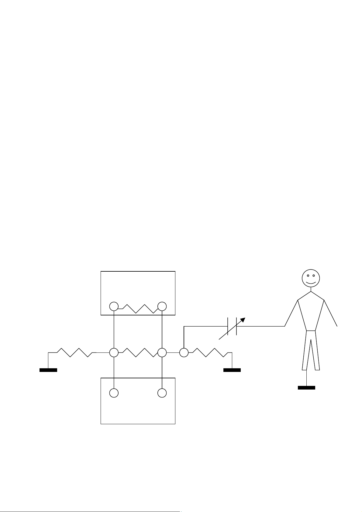
Even the presence of air currents can affect the results of the measurement.
The diagram below shows the stray resistance due to air conduction and the stray
capacitance, Sc, present between the operator and the measuring circuit.
RESISTANCE
BEING MEASURED
Sc
INSTRUMENT
-7-
Page 10

3 Preparing the instrument for use
3.1 Initial checks
Before being shipped, the instrument is checked from an electrical and a mechanical point
of view.
Every precaution has been taken so the instrument can be delivered without damage.
However the user is advised to look the instrument over quickly in order to check for any
damage during shipment. In case of any fault, contact the forwarding agent at once.
We also suggest making sure that the package contains every part listed under heading
6.4. In case of any discrepancy, contact the dealer.
Should it be necessary to return the instrument, please follow the instructions under the
heading 7.
3.2 Power supply for the instrument
The instrument is fed by 4 each, 1.5 volt, “D” size alkaline batteries (not included)
Endurance with new batteries is as follows:
250 measurements V = 5000 V Rx = 5 MΩ (minimum) t = 1 min.
450 measurements V = 500 V Rx = 500 kΩ (minimum) t = 1 min.
Before measuring, make sure that the "low battery” indicator is not lit (chap. 4.2, symbol
4).
When the "low battery” indicator is lit, measurements can still be performed, but with very
low resistance, it might not be possible to reach the rated voltage, and the measurement
would not be valid.
3.3 Storage
If the instrument has been kept in a cold environment and the measurement must be
performed in a warm place, the sharp change in temperature would make humidity
condense and this would falsify the measurement.
In this case, 15 min. must be allowed for the instrument to stabilise its temperature and
allow the condensation to evaporate.
-8-
Page 11

4 Working instructions
4.1 Description of the instrument
Legend:
1. Instrument ON/OFF switch.
2. Negative high voltage jack.
3. GUARD jack.
4. Positive high voltage jack.
5. An example of measurement connection using the GUARD.
6. Measuring range graph.
7. Display.
8. An example of measurement connection without using the GUARD.
9. Keyboard.
10. Serial port connector RS 232.
Note:
On the front of the instrument, under the handle, there is a “purge” knob.
This knob can be opened to vent the case to assist in the opening of the case
following a high altitude flight.
-9-
Page 12

4.2 Display
Legend:
1. "Measuring underway" indicators. When flashing: voltage delivery; when fixed ON:
circuit discharge.
2. "Measured value" indicator or indication of the current parameter memory number.
3. Unit of measure.
4. "Low Battery” indicator.
5. "Current measuring mode" indicator.
6. "Current RS 232 connection" indicator.
7. "Printing underway" indicator.
8. Remote control performance indicator.
9. "AUTO measure mode" indicator (lit during measuring).
10. Voltage indicator:
• Before measuring, this displays the voltage at the test leads.
• While measuring, the delivered voltage is displayed.
11. Measuring time indicator in TIMER or PROGR. mode.
12. Indicator of the polarity of the voltage being read.
13. This indicates the voltage parameter V2.
14. This indicates the voltage parameter V1.
15. This indicates the time parameter T1.
16. This indicates the time parameter T2.
17. Bar graph.
-10-
Page 13

4.3 Keyboard
Legend:
1. Decrease key This modifies the voltage or time setting.
This displays the locations of the measurement models.
2. Increase key This displays the saved performed measurements.
3. Confirmation or end of current operation.
4. Choosing the mode (MAN / AUTO / TIMER / PROGR) or deletion procedure.
5. Recalling stored measurements.
6. Saving the measurement parameters, the measurements that were performed and
printing out the measurements in the memory (from the displayed number to the last
one).
7. Starting up or stopping the measurement.
8. Turning the instrument on after automatic turn-off.
}
-11-
Page 14

4.4 Summary of the measuring modes
The instrument was designed for simple programming, so as to cut down the time needed
to prepare measuring.
The instrument is equipped with 25 memory locations (parameters – P) for storing the
various ways of measuring:
Configuration Factory setting Modifiable
P01 - P19 Yes yes
P20 - P25 Yes no
Each configuration can be reached both by the increase and by the diminish key, as these
work in a circular fashion: decreasing from P01 leads to P25, increasing from P25 leads to
P01. This makes it possible to reach the location of interest as soon as possible.
The purpose of the pre-set configurations is to allow performance of measures without
wasting time in setting up.
The purpose of the non-modifiable configurations is that of making the most common
insulation measurement types constantly available.
Description of the measuring parameters
• Voltage V2: Final voltage value wanted for test performance.
• Time T2: Duration time for voltage V2.
• Voltage V1: Starting voltage during measuring (only in PROGR mode).
• Time T1: The time for the output voltage to rise from the voltage value V1 to
the value V2 (only in PROGR mode).
This instrument is designed for use in a simple and intuitive manner, and provides the
following possibilities:
- Direct use of the factory-set configurations for the most frequent cases.
- Direct use of previously set configurations.
- Extemporaneous configurations when the measurement is not included among
those already present.
-12-
Page 15

4.4.1 Factory-set configurations
Following are the keyboard sequences for obtaining the configurations, with the instrument
at rest, starting from programme P01
P n. Keyboard sequence Parameters Kind of
test
P25 once the Diminish key, twice the Start key 500 1’ (minute) Timer
P24 twice the Diminish key, twice the Start key 1000 1’ (minute) Timer
P23 3 times the Diminish key, twice the Start key 2500 1’ (minute) Timer
P22 4 times the Diminish key, twice the Start key 5000 1’ (minute) Timer
P21 5 times the Diminish key, twice the Start key 5000 2’ (minutes) Timer
P20 6 times the Diminish key, twice the Start key 2500 10’ (minutes) Timer
P5-19 N times the Increase key, twice the Start key 500 Manual
P04 3 times the Increase key, twice the Start key 5000 Manual
P03 twice the Increase key, twice the Start key 2500 Manual
P02 once the Increase key, twice the Start key 1000 Manual
P01 Twice the Start key 500 Manual
-13-
Page 16

4.4.2 Previously memorised configurations
When performing the same measurements on the same kind of equipment, a measuring
configuration can be memorised for each usual situation, for example:
• P01 Measuring on A-type product.
• P02 Measuring on B-type product.
• P03 Measuring on C-type product.
The measuring configurations can also be divided up into groups used by different
operators. E.g.:
• P01 - P05 Measurements usually performed by operator 1
• P06 - P10 Measurements usually performed by operator 2
• P11 - P15 Measurements usually performed by operator 3
In each case, all that is required is for the operator to use the arrow keys to go to the
desired configuration and then to press Start to begin measuring.
4.4.3 Extemporaneous instrument configuration
Select a configuration and modify it as described under Section 4.5, Instrument
Configuration and Measurement Performance, then use the Start key to run it. If the
modified configuration is not saved, it will stay active only until a new selection is made or
the instrument is turned off.
-14-
Page 17

4.5 Instrument configuration and measurement performance
Following is a description of the parameters and way the values are set.
4.5.1 Measurement preparation selection
To prepare the measurement, press the increase or decrease key to run through the
memories until reaching the location you intend to introduce the configuration into.
4.5.2 MAN Mode
KEY OPERATION
Memorisation is possible only from cell P01 to cell P19.
NOTICE
MAN
Ø × Reach the memory cell you are interested in.
ModE Press the MODE key repeatedly to display the MAN measuring mode.
SeT The V2 parameter indicator is flashing.
Ø × Set the V2 voltage value you want (testing voltage). The top secondary
display (item 10 par. 4.2) will show the value you are setting.
SeT Exit the programming phase. The flashing measuring mode advises you that
you can save the settings.
SavE Saving the parameters in the location first selected (if requested).
StarT “Go?” prompt displayed, PRESS START again and HOLD DOWN UNTIL
READING STABILISES.
4.5.3 AUTO Mode
KEY OPERATION
AUTO
Ø × Reach the memory cell you are interested in.
ModE Press the MODE key repeatedly to display the AUTO measuring mode.
SeT The V2 parameter indicator is flashing.
Ø × Set the V2 voltage value you want (testing voltage). The top secondary
display (item 10 par. 4.2) will show the value you are setting.
SeT Exit the programming phase. The flashing measuring mode advises you that
you can save the settings.
SavE Saving the parameters in the location first selected (if requested).
StarT “Go ?” prompt displayed, PRESS START again to start measuring.
-15-
Page 18

4.5.4 TIMER Mode
KEY OPERATION
TIMER
Ø × Reach the memory cell you are interested in.
ModE Press the MODE key repeatedly to display the TIMER measuring mode.
SeT The V2 parameter indicator is flashing.
Ø × Set the V2 voltage value you want (testing voltage). The top secondary (item
10 par. 4.2) will display the value you are setting.
SeT The T2 parameter indicator is flashing.
Ø × Set the T2 time value (duration of the measurement). The bottom secondary
display (item 11 par. 4.2) will show the value you are setting. The shortest
time that can be set is 15” (seconds).
SeT Exit the programming phase. The flashing measuring mode advises you that
you can save the settings.
SavE Saving the parameters in the location first selected (if requested).
StarT “Go ?” prompt displayed, PRESS START again to start measuring.
4.5.5 PROGR Mode
KEY OPERATION
PROGR
Ø × Reach the memory cell you are interested in.
ModE Press the MODE key repeatedly to display the PROGR measuring mode.
SeT The V2 parameter indicator is flashing.
Ø × Set the V2 voltage value you want (testing voltage). The top secondary
display (item 10 par. 4.2) will show the value you are setting.
SeT The T2 parameter indicator is flashing.
Ø × Set the T2 time value (duration of the measurement). The bottom secondary
display (item 11 par. 4.2) will show the value you are setting. The shortest
time that can be set is 15” (seconds).
SeT The V1 parameter indicator is flashing.
-16-
Page 19

Ø × Set the V1 voltage value you want (testing start voltage). The top secondary
display (item 10 par. 4.2) will show the value you are setting.
NOTE: The value of V1 CANNOT be greater than that of V2.
SeT The T1 parameter indicator is flashing.
Ø × Set the T1 time value (duration of the rising voltage ramp from value V1 to
value V2). The bottom secondary display (item 11 par. 4.2) will show the
value you are setting. The shortest time that can be set is 15” (seconds).
SeT Exit the programming phase. The flashing measuring mode advises you that
you can save the settings.
SavE Saving the parameters in the location first selected (if requested).
StarT “Go ?” prompt displayed, PRESS START again to start measuring.
4.5.6 Measurement of polarization index
PI
MEGA
EST
T
5000
Insulator
It’s common knowledge that a good insulator, if subject to voltage, shows a gradual
resistance increase over a period of time. Vice versa, a resistance decrease indicates bad
quality of the insulator (or presence of dirt affecting the measurement).
The polarization index is defined as the ratio between the resistance value measured after
10 minutes and the resistance value measured after 1 minute from application of the test
voltage. Therefore it’s an important indicator of the insulator quality. Indicative information
about the insulator features, but not so accurate as the polarization index, are provided by
the ratio between the resistance value measured after 60 seconds and the resistance
value measured after 30 seconds. Already after one minute it’s possible to verify if the
resistance value has considerably increased (as hoped) or, on the contrary, it’s unchanged
or, still worse, it has decreased.
-17-
Page 20

This measuring method, based on resistance ratios, gives a dimensionless result,
independent on a series of factors such us equipment size, temperature or environmental
conditions.
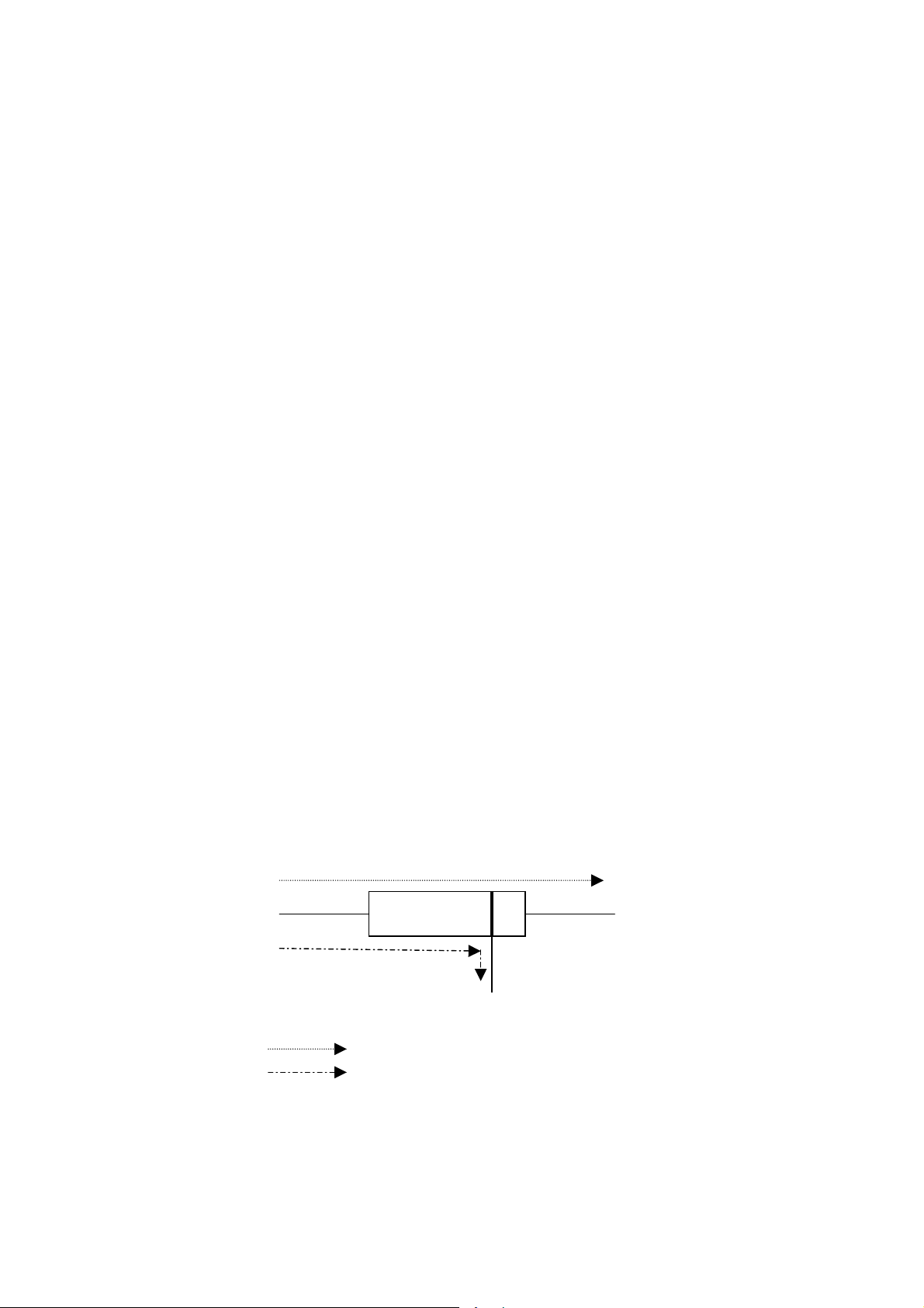
Insulator status 60/30 sec ratio Polarization index
10/1 min ratio
dangerous ─── less than 1
questionable
good
excellent more than 1.6 more than 4
Tab. 1: Insulator status as revealed by the polarization index.
The measurement of the polarization index of a dielectric can be taken by manufacturers
of electrical equipment to test, for example, materials to be used for the production of
supports for conductors, components and devices, insulation of motor coils.
KEY OPERATION
1.0 ÷ 1.25 1.0 ÷ 2
1.4 ÷ 1.6 2 ÷ 4
Ø × Reach the memory cell P20. PI is displayed.
SeT The V2 parameter indicator is flashing.
Ø × Set the desired V2 voltage value (test voltage) between 100 and 5000V. The
top secondary display will show the value you are setting.
SeT The T2 parameter indicator is flashing.
SeT Leave the programming phase. The flashing measuring mode TIMER
advises that you can save the settings.
SavE Save the parameters in the location previously selected (if requested).
StarT The message “go?” is displayed.
StarT The measurement is started.
• The test can be interrupted at any time (provided that at least 75 seconds have passed
from starting).
• At the end of the measurement the PI value is displayed. Press MODE to display the
last resistance value measured.
• Press SAVE to store the measured values.
• It’s possible to recall the measured values. Press SET/EXIT to run over the PI values,
the resistance values and the measuring parameters.
-18-
Page 21

4.6 Examples of insulation measurement
Connect the terminals of the insulation you want to measure to the high voltage jacks.
Connect the Guard to a suitable point near the negative terminal (ref. "Use of the
GUARD" – heading 2.5).
o
p
4.6.1 Measuring the insulation of the windings of an electrical machine
Comply with the instructions in the manual, especially refer to chapter 1.
"Accident prevention and safety measures". Improper use could lead to
damage to the instrument or to the equipment being tested.
WHILE MEASURING DO NOT TOUCH THE CONNECTIONS OF THE TEST
LEADS.
The instrument is equipped with a discharge circuit for the capacities
connected to the measuring terminals. When measuring has been completed,
therefore, DO NOT DISCONNECT THE TEST LEADS UNTIL THE
"MEASUREMENT UNDERWAY" SYMBOLS HAVE DISAPPEARED
WARNING
.
MEGA EST
T
5000
This measurement can be employed by manufacturers and repair engineers of electric
motors or transformers in order to check out the efficiency of the product and its
compliance with specific regulations.
• Connect the instrument between the frame (on a paint-free part) and the windings
(connect these to each other if they are separated) of the motor.
• Pre-set configurations can be used, for example choosing P25 with the up or down
arrows, one can set a measurement at 500 V for 1’ (minute).
• Should you intend to perform tests using other parameters, choose the appropriate
settings (ref. Section 4.5)
-19-
Page 22

• Press START, wait until the measuring is over and make sure the value measured is
consistent with what you requested.
• If necessary, save the measurement you performed by pressing the SAVE key (ref.
chapter 4.7).
4.6.2 Measuring on a power plant
Technicians and repair engineers may use this instrument in order to check out the
efficiency of the system and its compliance with specific regulations.
• Connect the instrument between each cable to be tested and the ground.
• Pre-set configurations can be used. For example, use the up or down arrow keys to
select P25: this will set a measurement of 500 V for 1’ (minute).
• Should you intend to perform tests using other parameters, choose the appropriate
settings (ref. chapter 4.5).
• Press START, wait until the measuring is over and make sure the value measured is
consistent with what you requested.
• If necessary, save the measurement you performed by pressing the SAVE key (ref.
chapter 4.7).
4.6.3 Checking the efficiency of an insulator
MEGA
EST
T
5000
Insulating
Material
-20-
Page 23

This measurement can be employed by manufacturers of electrical equipment to check
materials, such as supports for conductors, components and equipment.
• Connect the test leads to the material being tested, placing them at the distance to be
verified and making sure there is proper contact.
• Pre-set configurations can be used. For example, use the up or down arrow keys to
select P20: this will set a measurement of 2500 V for 10’.
• Should you intend to perform tests using other parameters, choose the appropriate
settings (ref. chapter 4.5).
• Press START, wait until the measuring is over and make sure the value measured is
consistent with what you requested.
• If necessary, save the measurement you performed by pressing the SAVE key (ref.
chapter 4.7).
4.6.4 Estimating the insulating strength
MEGA
EST
T
5000
Insulating
Material
This measurement can be employed by manufacturers of electrical equipment to check
materials for example for making supports for conductors, components and equipment.
• Connect the test leads to the material being tested, placing them at the distance to be
verified and making sure there is proper contact.
• Pre-set configurations can be used. For example, use the up or down arrow keys to
select P21: this will set a measurement of 5000 V for 2’ (minutes) with a ramp increase.
• Should you intend to perform tests using other parameters, choose the appropriate
settings (ref. chapter 4.5).
• Press START and observe the value of the resistance during the test.
• Stop the test manually (STOP key) as soon as the resistance starts to diminish or as
soon as there is a discharge. The voltage reached before stopping the test is the
maximum applicable voltage, and a reasonable safety margin should be kept
compared to it.
• If necessary, save the measurement you performed by pressing the SAVE key (ref.
chapter 4.7).
• If you want, you can proceed to test the efficiency of the insulator.
-21-
Page 24

4.7 Saving the measurements which were performed
Once measurement has been finished, you can press the SAVE key to save the
performed measurement with all the parameters employed during testing.
The top secondary display (item 10 par. 4.2) shows for three seconds the number of the
memory location where the measurement was memorised. Up to 200 measurements can
be memorised.
4.8 Recalling memorised measurements
KEY OPERATION
Recall With the instrument in waiting condition (i.e. when there are no current
operations), press Recall to read all stored measurements. The last one to
be performed will be the first to be displayed. The number of the
measurement is shown on the top secondary display (item 10 par. 4.2).
Ø × These allow you to run through all the measurements stored in memory (with
an overall total of 200 measurements).
SeT This displays all the parameters the measurement was performed with on the
relevant displays.
Recall This shuts down the memory recall mode and goes back to the waiting
condition.
4.9 PRINTING OUT MEMORISED MEASUREMENTS
Note
: Connect the instrument to your PC using the RS 232 serial cable provided. (see
Section 4.13)
KEY OPERATION
Recall With the instrument in waiting condition (i.e. when there are no current
operations), press Recall to enter the measurement display mode.
Ø × Reach the memorised measurement you want to start printing from. The
number of the measurement is shown on the top secondary display (item 10
par. 4.2).
PrinT Start printing out the measurements, from the displayed one to the last one.
To interrupt printing, keep SET/EXIT pressed
Recall This shuts down the memory recall mode and goes back to the waiting
condition.
until printing stops.
-22-
Page 25

4.10 Deleting memorised memories
KEY OPERATION
Recall With the instrument in waiting condition (i.e. when there are no current
operations), press Recall to enter the measurement display mode.
Ø × This reaches the memory location you want to start deleting with. The
number of the measurement is shown on the top secondary display (item 10
par. 4.2).
CleaR The initials "clr" are displayed on the bottom secondary display (item 11 par.
4.2). To cancel deletion press SET/EXIT.
CleaR Confirm deletion command: every location is deleted from the one
displayed to very last one. Once the operation is over, the location
previous to the one where deletion was started will be displayed. If deletion
starts from location No. 001, the instrument will go automatically back to its
waiting condition.
Recall Exit from the memory mode if you did not exit it already during deletion (see
previous item).
4.11 Restoring the initial configuration
To clear the memory of the instrument completely, proceed as follows:
• Turn the instrument off.
• Keep the MODE/CLR key pressed while turning the instrument back on.
• After a few seconds, the message "rES" will appear on the main display confirming that
resetting has taken place.
• Let the MODE/CLR key go.
This operation clears the entire memory of measurements and restores the initial condition
of the measuring configuration (ref. chapter 4.4.1).
4.12 Error code description
Should there be an error, one of the following messages will appear on the display:
Er0: the memory of performed measurements is full.
Er1: the circuit being measured was not discharged correctly within the maximum time.
op
When the message Er1 is present, discharge the system manually,
WITHOUT TOUCHING ANY LIVE PART. Then check for any break in
the connections.
CAUTION
-23-
Page 26

4.13 Use of the serial port
Connect the instrument to the serial port of your PC using the 9 pin RS 232 serial cable
provided.
In case your PC has a 25-pin connector simply use a standard 9 pin to 25 pin adapter (not
provided)
4.13.1 Reading and downloading the results of the measurements on a computer
If the “SUPERLINK” software has previously been installed, simply turn the instrument on
and start up the “SUPERLINK” Program on the computer.
To install the “SUPERLINK” software refer to the instructions on the floppy disk or CD.
Refer to the “Help” menu on the “SUPERLINK” for information on software use.
-24-
Page 27

5 Maintenance
5.1 Replacing the batteries
• Before opening the lid of the battery compartment, disconnect the
test leads from the instrument.
op
When the "low battery” indicator (chap. 4.2, symbol 4) appears on the instrument, replace
the batteries.
Measurements can still be performed with the "low battery” indicator lit, but on very low
resistance, the rated voltage might not be achieved; in this case, the results would no
longer be valid.
- Finish any measurement you may be performing.
- Wait for the output voltage to finish discharging.
- Turn the instrument off.
- Disconnect the test leads.
- Use a screwdriver or coin to remove the 4 screws on the battery compartment door,
located on the bottom of the instrument.
- Use 4 each, 1.5-volt, “D” size alkaline batteries.
- Always use fresh batteries to replace the used ones, and replace all the batteries at
the same time (no partial replacement).
• Always make sure the system has finished discharging before
disconnecting the test leads or opening the battery compartment.
CAUTION
5.2 Cleaning the instrument
Clean the instrument regularly in order to remove any dust or other residue, which could
conduct current or falsify the results of the measurements.
To clean the instrument, use a soft and dry cloth, which can be lightly dipped in alcohol.
Never use damp cloths, solvents, water, etc.
-25-
Page 28

6 Technical specifications
6.1 Technical features
Accuracy is shown in terms of [% of the reading + number of digits]. It refers to the
following ambient conditions: temperature 73°F +/- 2° (23 °C +/- 1°) with relative humidity
< 75%.
6.1.1 Measuring the insulation.
Range
100 .. <500 V 500 .. <1000 V 1000 .. 2500 V 2500 .. 5000 V
100 K - 500 K
500 K - 50 G
50 G - 100 G
100 G - 250 G - - -
±(20% + 10dgt) ±(20% + 10dgt) ±(20% + 10dgt) ±(20% + 10dgt)
±(5% + 1dgt) ±(5% + 1dgt) ±(5% + 1dgt) ±(5% + 1dgt)
±(20% + 10dgt) ±(5% + 1dgt) ±(5% + 1dgt) ±(5% + 1dgt)
±(20% + 10dgt) ±(5% + 1dgt) ±(5% + 1dgt)
250 G - 500 G - - - - - -
Minimum resistance resolution: 1%
Voltage indication resolution: 1.22 V
6.1.2 Current which can be delivered
Voltage setting Max current
Accuracy
±(20% + 10dgt) ±(5% + 1dgt)
100 - 500 V 3.00 mA
1000 - 5000 V 1.40 mA
The output current is automatically limited.
6.1.3 Voltage measurement
Voltage range Resolution Accuracy
0 - 500 V 1,22V
500 - 5000 V 1,22V
±(10%+10 dgt)
±(10%+ 5 dgt)
The limits shown here are valid both for DC of any polarity and for AC.
Discharge time at 5000V: <1.5s x µF.
6.1.4 Safety
Instrument according to standard: EN 61010-1
Insulation: Class 2, Double insulation
Pollution level: 2
Indoors use; max altitude: 6,562 feet (2000 m)
Over-voltage category: CAT III 600V
Serial port insulation: 25 mm. (max. 5000 V)
-26-
Page 29

6.2 General features
6.2.1 Electric features
Measuring method: voltamperometric system
Parameter memory: 20 different parameters
Stored measurements: 200 measurements with their parameters and results
RS232: DIN 9 pin
6.2.2 Safety
The measurement is stopped when there is voltage at the test leads that could
damage the instrument.
Discharge of the remaining voltage at the end of the measurement or when the
instrument has been turned off.
6.2.3 Mechanical features
Size: 290(L) x 340(W) x 145(H) mm
11.5(L) x 13(W) x 5.75(H) inches
Weight 8.8 Lbs. (4 Kg)
6.2.4 Power supply
Battery Type: 4 each, 1.5 volt, “D” size alkaline
"Low Battery" indication: “Battery” symbol appears on the display
Endurance: 250 meas. V = 5000 V Rx = 5 MΩ t = 1 min
450 meas. V = 500 V Rx = 500kΩ t = 1 min
Automatic Turn Off Turns off after 10 minutes without use.
6.2.5 Display
Features: LCD 1 unit 3 dgt., 2 units 4 dgt., bargraph 32
Updating speed: max. 2 sec. depends on the value of the
segments + other symbols.
resistance being measured and on the stray
capacitance present in parallel. During the first 15
sec. the resistance value is shown as “- - -“).
6.3 Ambient conditions
6.3.1 Ambient conditions of use
Temperature of reference: 73° F +/- 1° (23°C +/- 1°)
Operating Temperature: 41 - 104° F (5 - 40°C)
Permitted relative humidity: < 80%
Storage temperature: 14 –140° F (-10 - 60 °C)
Storage humidity < 70%
Noise level: < 40 dB
6.3.2 EMC
This instrument has been designed to comply with current EMC standards and
electromagnetic compatibility has been tested under:
EN 50081-1, EN 50082-1
This instrument complies with the requirements of the European Directive on low
voltage 72/23/EEC and with the EMC 89/336/EEC directive, modified under
93/68/EEC.
-27-
Page 30

6.4 Standard equipment
The package contains:
• The instrument received
• Three test leads provided with a safety boot and an alligator clip
• Instruction manual
• Serial cable for computer connection
• CD-ROM with “SUPERLINK” software for downloading/reading measurements
6.5 Replacement parts
Part Description
Carrying Case MT5-CC
Download Cable GP-RS232
Test Leads Set (complete set of 3) MT5-LEADS
Part #
-28-
Page 31

7 Warranty conditions
Congratulations! You are now the owner of an AMPROBE
Instrument. It has been quality crafted according to
quality standards and contains quality components and
workmanship. This instrument has been inspected for
proper operation of all of its functions. It has been
tested by qualified factory technicians according to the
long -established standards of AMPROBE INSTRUMENT.
Your AMPROBE instrument has a limited warranty against
defective materials and/or workmanship for one year from
the date of purchase provided that, in the opinion of
the factory, the instrument has not been tampered with
or taken apart.
Should your instrument fail due to defective materials,
and/or workmanship during this one-year period, please
have your dated bill of sale which must identify the
instrument model number and serial number and call the
number listed below:
Service Division
AMPROBE INSTRUMENT
Miami, Florida 33150
Tel: 800-327-5060
Outside the U.S.A. the local Amprobe representative will
assist you. Above limited warranty covers repair and
replacement of instrument only and no other obligation
is stated or implied.
7.1 After-sales service
If the instrument fails to operate, check battery, test
leads, etc and replace as necessary. If the instrument
still malfunctions, please call the phone number listed
below:
---------------------------Service Division
AMPROBE INSTRUMENT
Miami, Florida 33150
Tel: 800-327-5060
Outside the U.S.A. the local Amprobe representative will
assist you.
-29-
Page 32

Miami, FL 33150
(305) 423-7500
(800) 327-5060
 Loading...