

Page 1
MEGATEST 1000
MEGOHMMETER
Model #: AMB-6D
Owner’s Manual
Page 2

1. OVERVIEW............................................................................................................................................................ 2
1.1 INITIAL INSPECTION .................................................................................................................................. 2
1.2 POWER SUPPLY ...........................................................................................................................................2
1.3 CALIBRATION.............................................................................................................................................. 2
1.4 STORAGE....................................................................................................................................................... 2
2. SAFETY PRECAUTIONS AND PROCEDURES...............................................................................................3
2.1 PRIOR TO USE .............................................................................................................................................3
2.3 DURING USE................................................................................................................................................. 4
2.4 AFTER USE.................................................................................................................................................... 4
3. INSTRUMENT DESCRIPTION........................................................................................................................... 5
3.1 ROTARY SWITCH POSITIONS ............................................................................................................................ 5
3.2 DEFINITION OF KEYS ........................................................................................................................................ 6
4. CALIBRATION PROCEDURE............................................................................................................................ 7
4.1 CANCELLATION OF CALIBRATION PARAMETERS............................................................................. 8
5. SWITCH POSITION FUNCTIONS:.................................................................................................................... 9
5.1 “LOWΩ” POSITION ...................................................................................................................................... 9
5.1.1 CONTINUITY TEST: ................................................................................................................................... 9
5.1.2 "AUTO", "R+", "R-", "R+TIMER", "R-TIMER" MODES: ...................................................................... 10
5.2 “MΩ” POSITION.......................................................................................................................................... 14
5.2.1 INSULATION RESISTANCE:................................................................................................................ 14
5.2.2 “MAN”, “AUTO”, “TIMER” MODES ...................................................................................................14
5.3 HOW TO SAVE, RECALL AND CLEAR TEST DATA ............................................................................21
5.3.1 SAVE........................................................................................................................................................ 21
5.3.2 RECALL....................................................................................................................................................22
5.3.3 CLEAR...................................................................................................................................................... 23
5.4 RESET PROCEDURE .................................................................................................................................. 24
5.5 DEFAULT PARAMETERS..........................................................................................................................24
5.5.1 DEFAULT PARAMETERS LOWΩ........................................................................................................... 24
5.5.2 DEFAULT PARAMETERS MΩ................................................................................................................ 24
5.5.3 MEMORY DEFAULT PARAMETERS......................................................................................................24
6. PRACTICAL EXAMPLES OF ELECTRICAL TESTS................................................................................... 25
6.1 LOW CONTINUITY MEASUREMENT ..................................................................................................... 25
6.2 INSTALLATION RESISTANCE.................................................................................................................26
6.3 CHECKING THE CIRCUIT SEPARATION............................................................................................... 30
6.4 MEASUREMENT OF FLOOR INSULATION RESISTANCE IN MEDICAL ROOMS CEI 64-4............ 32
7. CONNECTING INSTRUMENT TO PC ............................................................................................................ 34
8. PRINTING OF DATA ON SERIAL PRINTER (OPTIONAL) ....................................................................... 35
9. MAINTENANCE.................................................................................................................................................. 36
9.1 GENERAL ....................................................................................................................................................36
9.2 BATTERY REPLACEMENT....................................................................................................................... 36
9.3 INSTRUMENT CLEANING........................................................................................................................ 36
10. TECHNICAL SPECIFICATIONS................................................................................................................. 37
11. WARRANTY AND SERVICE CONDITIONS.............................................................................................40
1
Page 3

1. OVERVIEW
Thank you for purchasing the MEGATEST 1000, Model AMB-6D, from Amprobe. We
have been in the marketplace for over 50 years and are a leader in the field of electrical
measurement.
We intend to satisfy our customers’ requirements by continuing to provide increasingly
reliable and innovative products.
This instrument was designed to provide the user with the utmost safety features thanks to
a new concept assuring double insulation and over voltage category III classification.
1.1 INITIAL INSPECTION
This instrument has been checked mechanically and electrically prior to shipment and
every care has been taken to ensure that the instrument reaches you in the proper
working order.
It is recommended, however, that you carry out a quick check of the instrument to detect
any possible damage that may have occurred during transport. If any damage is observed
please contact your dealer immediately.
Check also that the packaging contains all the parts listed under paragraph 10.1. If there
are any discrepancies please contact the dealer.
In case you have to send the instrument back please follow the instructions reported in
paragraph 11.
1.2 POWER SUPPLY
The AMB-6D is powered by six each, 1.5 Volt, “AA” alkaline batteries (not included).
For battery life information see paragraph 10.
When batteries are low the “battery symbol” is displayed.
To replace batteries follow the instructions in paragraph 9.2.
1.3 CALIBRATION
This instrument fulfils the technical specifications listed in this manual. The performance to
these specifications is guaranteed for one year. Annual re-calibration is recommended.
1.4 STORAGE
In order to ensure the accuracy of the measurements, after a period of storage in extreme
environmental conditions, wait for the time necessary so that the instrument is back to
normal measuring conditions (see environmental specifications listed in Section 10).
2
Page 4

2. SAFETY PRECAUTIONS AND PROCEDURES
2.1 PRIOR TO USE
Please read and understand the following instructions BEFORE
instrument can generate dangerously high voltages.
using the AMB-6D. This
o WARNING: For your own safety, as well as the instrument and equipment
you are testing, it is recommended that you follow the
procedures described in this instruction manual and carefully
read all the notes preceded by the symbol
Strictly follow these instructions before and during measurements:
Do not take measurements in environments with explosive gas, fuels or dust.
Do not take measurements in wet environments.
Do not touch exposed metal parts; i.e. alligator clips, ends of test leads, circuits, etc.,
while taking measurements.
.
Prevent any accidental contact of others with the measuring voltage.
Make sure the test voltage does not damage any component unable to withstand it.
Do not take any measurement in case of unusual conditions with the instrument such
as deformation, breakage, leakage of substances, absence of display reading etc.
The AMB-6D can be used for tests on electrical installations with over voltage category
III up to 250V (to Earth).
You are recommended to comply with the standard safety regulations aimed at:
Protecting you against dangerous currents.
Protecting the instrument against improper use.
Use only the test leads supplied with the instrument. They must be in good condition
and if they require replacement, they must be identical to those supplied with the
instrument (See Replacement Parts, paragraph 10.2)
Do not take measurements on circuits exceeding the specified voltage limits.
Do not take any measurement under environmental conditions beyond the limits
specified in Section 10.
Check that batteries have been installed correctly.
Before connecting test leads to the circuit under test, check to be sure that the rotary
switch is in the correct position.
Check that LCD and rotary switch indicate the same function.
3
Page 5
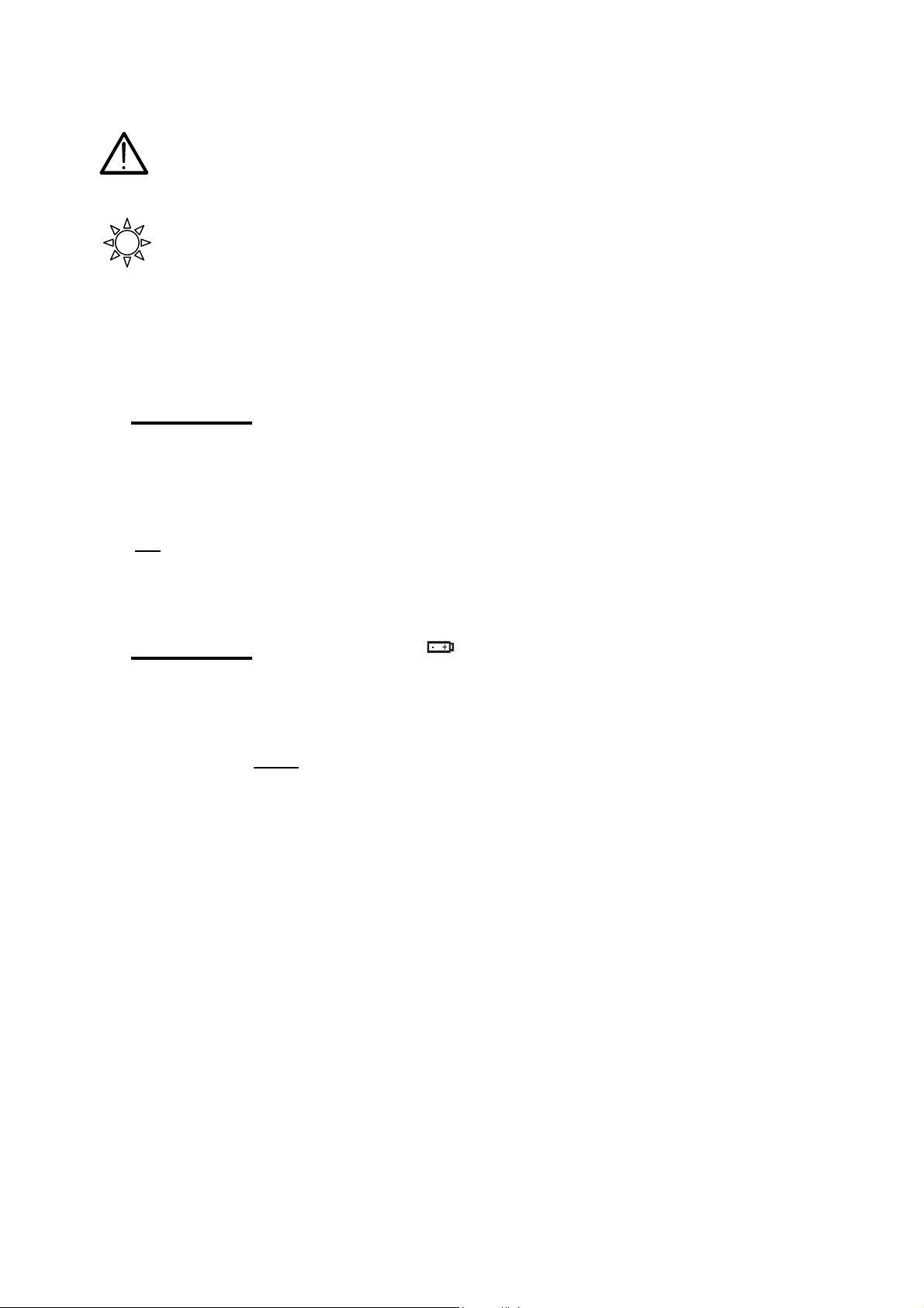
The following symbols are used in this manual:
Caution: refer to the instructions reported in this manual; improper use may
damage the apparatus or its components.
Rotary switch of the instrument.
2.3 DURING USE
Carefully read the following recommendations and instructions:
o WARNING: Non compliance with the Warnings and/or Instructions may
damage the instrument and/or its components or injure the
operator.
Before selecting any function disconnect the test leads from the circuit under test.
When the instrument is connected to the tested circuit never touch any test lead which
is not
being used.
Avoid taking resistance measurements in the presence of external voltages; even
though the instrument is protected, high voltage may cause malfunctions.
o WARNING: If the symbol is displayed during use interrupt testing and
replace batteries following the procedure described under
paragraph 9.2.
Note: The instrument is capable of keeping the data stored even
though batteries are not installed.
2.4 AFTER USE
After the measurements are completed turn the rotary switch to the “OFF” position.
Remove batteries if the instrument is to remain unused for long periods of time.
4
Page 6
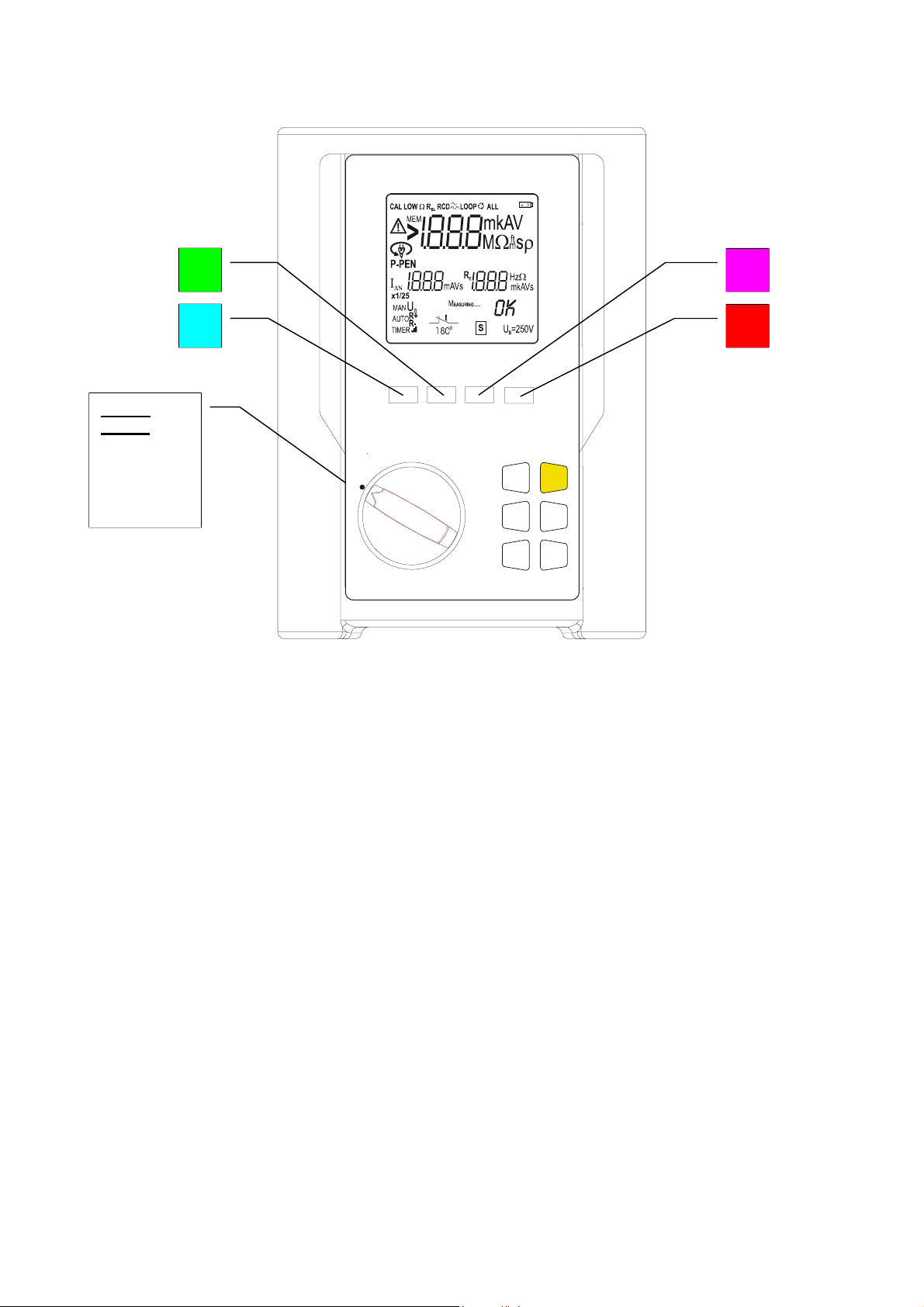
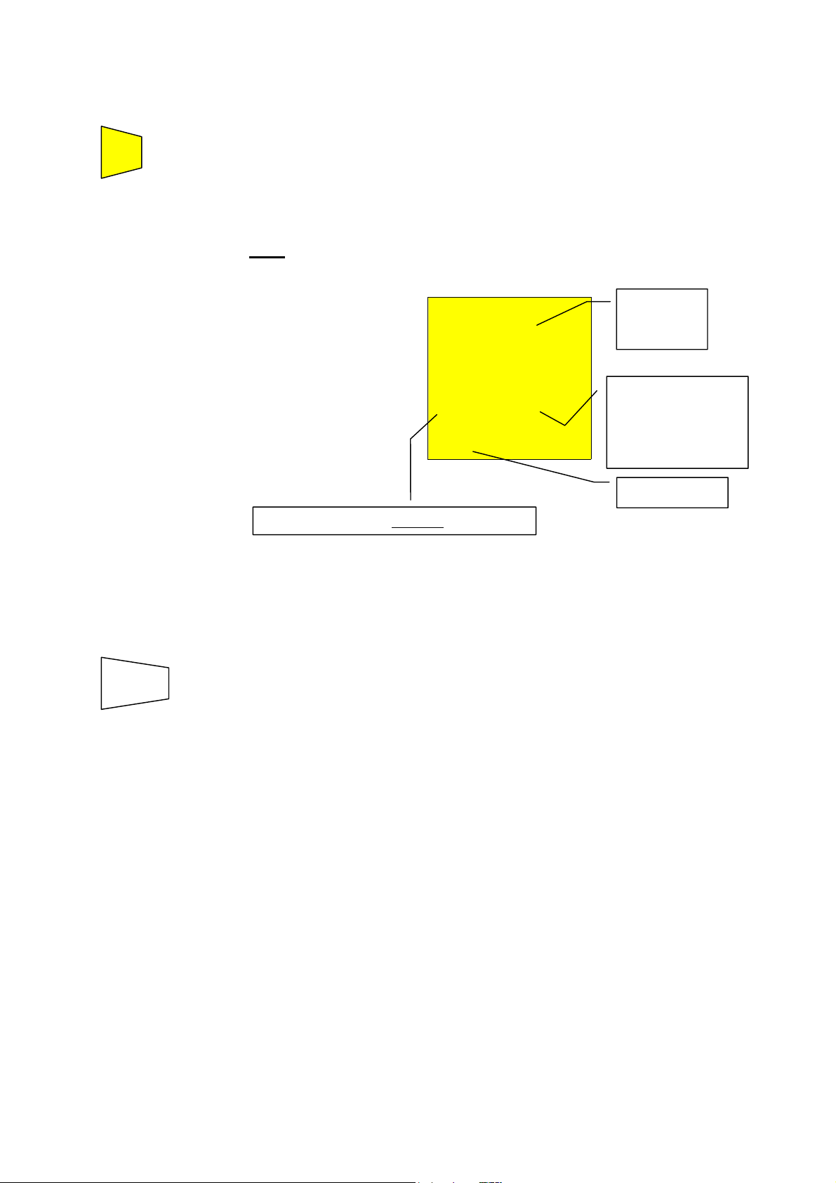
3. INSTRUMENT DESCRIPTION
Rotary
switch:
Selects the
instrument
function
2
1
OFF
DISPLAY
CLEAR
RECALL
GO
ESC
SAVE
3
4
Front panel of the Instrument
3.1 Rotary Switch Positions
LOWΩ: Continuity test of earth, protective and equalising potential conductors with test
current higher than 200 mA and open circuit voltage ranging from 4V to 24V.
MΩ: Measurement of insulation resistance with DC test voltage 50V, 100V, 250V,
500V or 1000V.
RS232 To transfer stored data or print via a PC.
5
Page 7
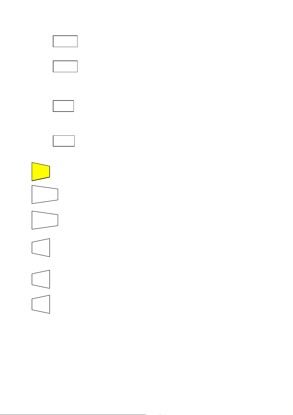
3.2 Definition of Keys
#1 Multifunction key to select measuring mode.
#2 Key for selection the rated voltage during test of insulation
#3 Key used to increase the test duration interval or to scroll the
#4 Key used to decrease the test duration interval or to scroll the
GO
GO
ESC
SAVE
RCL
DISP
CLR
FUNC
U
n
resistance.
▲
results of the stored tests.
▼
results of the stored tests.
Key to start or stop tests.
Key to quit the function or selected mode.
Key to save tests.
Key to recall the stored tests.
Key to displays test results at selected memory locations
Key to cancel the stored tests.
6
Page 8
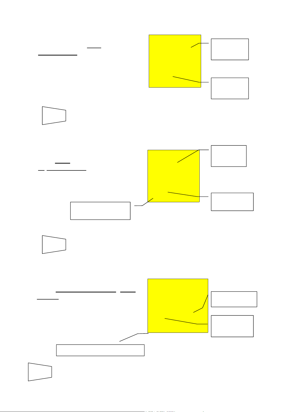
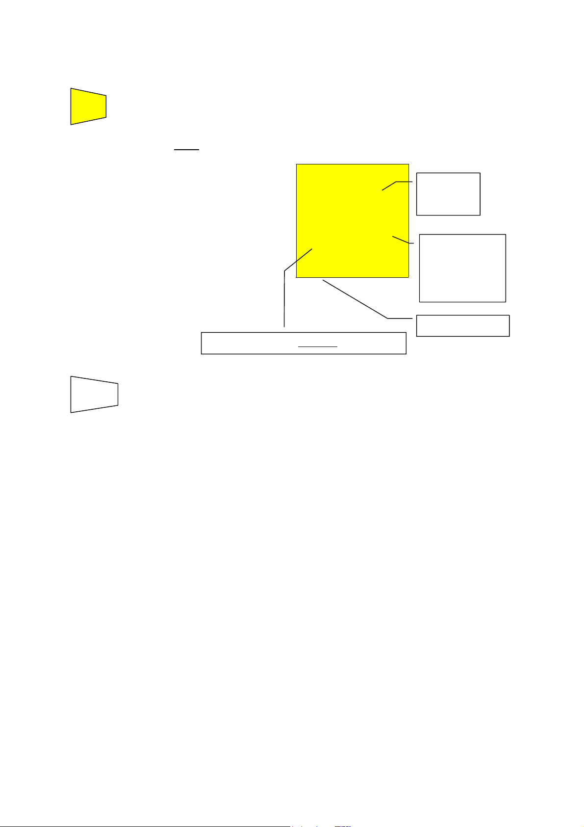
4. CALIBRATION PROCEDURE
A
r
t
p
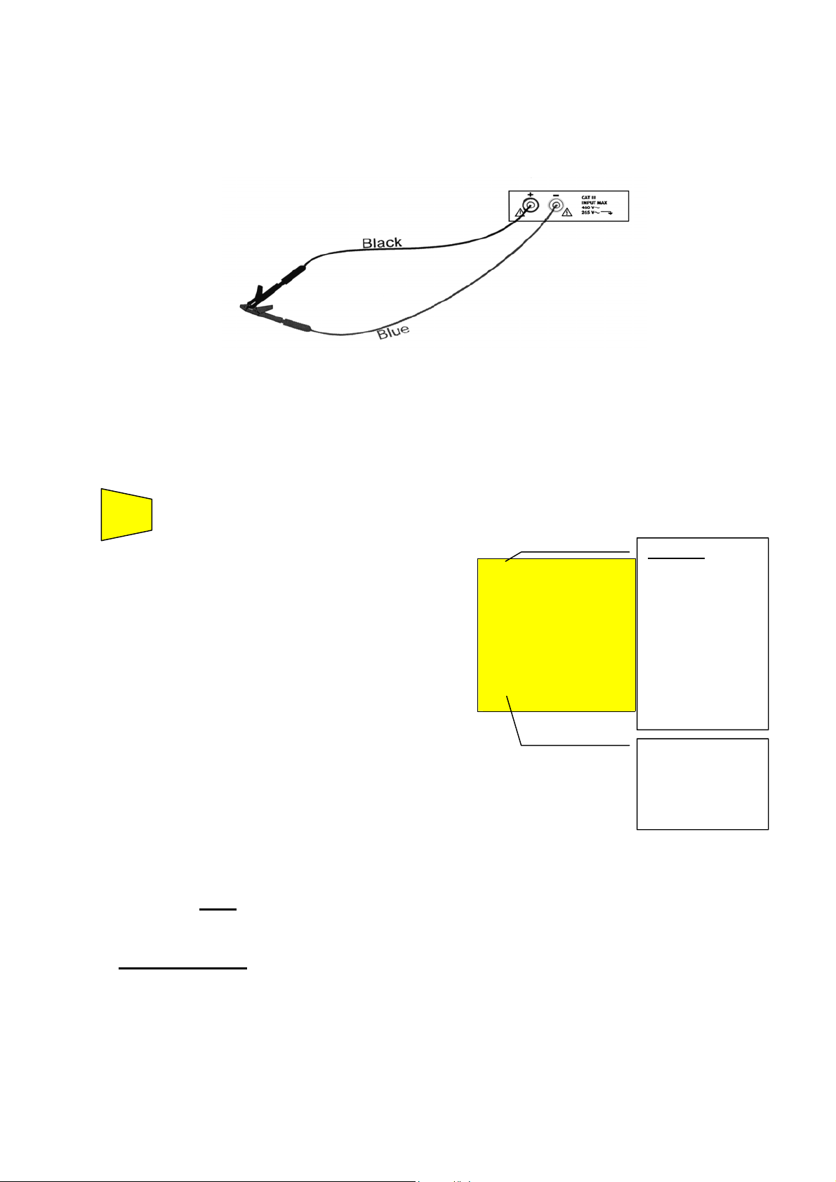
1. Select mode CAL by means of the FUNC key.
2. Connect the black and blue cables to the instrument input terminals P and N
respectively:
Connection of instrument terminals during calibration procedure.
3. Connect the alligator clips to the test leads.
4. Short-circuit the test leads by joining the alligator clips together, making sure there is good
contact between them. (See figure above).
6. Press the GO key. The instrument carries out the calibration.
GO
Note
t the end of the test the
result is stored and used as
an OFFSET (that is to say
that it is subtracted from
any continuity test
carried out) for all the
subsequent measurements
until a new calibration is
carried out.
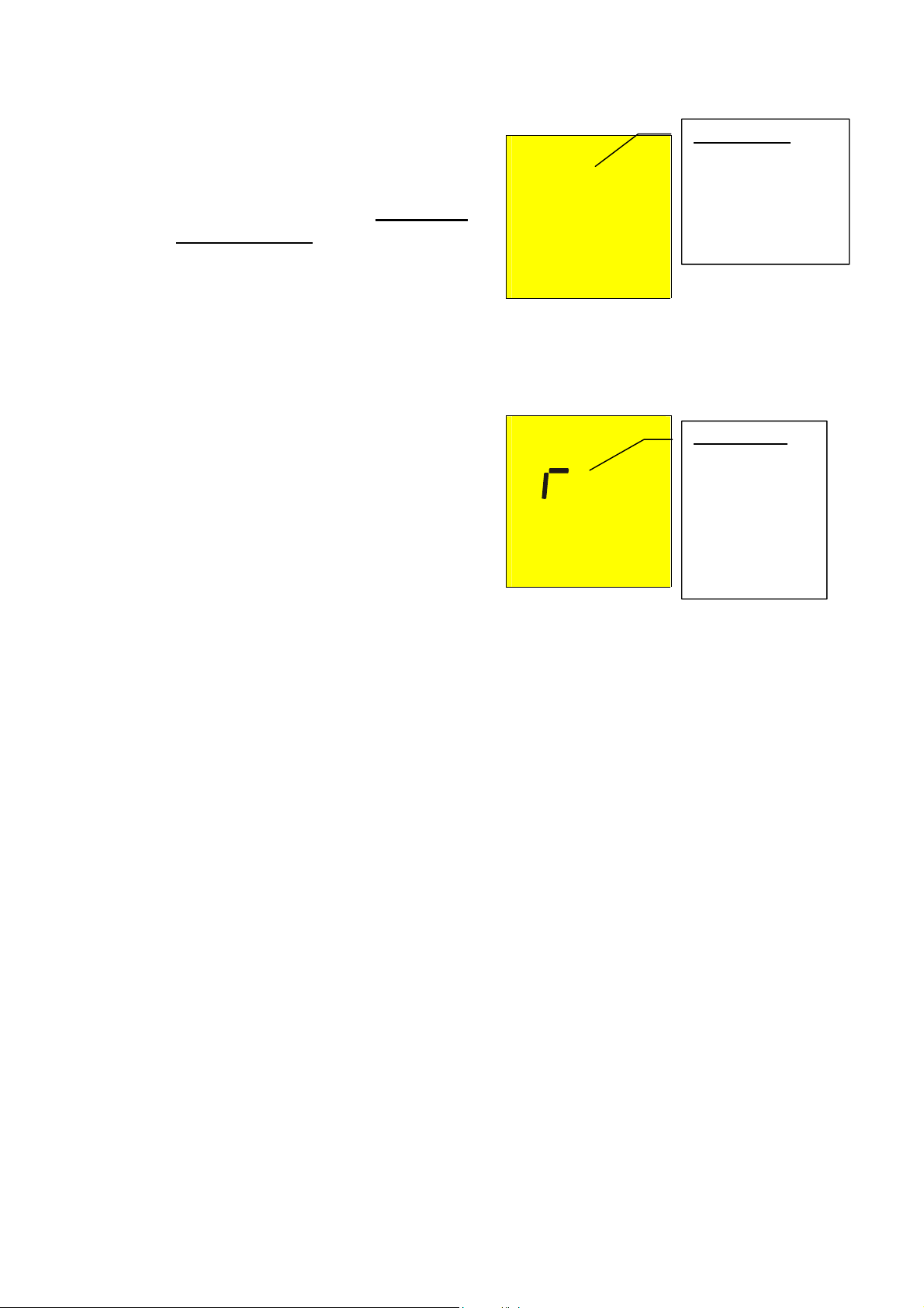
This screen is displayed for only 2 seconds then
the instrument emits a double sound signal
(indicating that the calibration is completed) and
displays the default screen relative to the LOWΩ test
under AUTO mode.
: The instrument compensates for resistance of the cables when the
resistance is lower than 5Ω.
CAL LOWΩ
0.00 Ω
203 mA
Message CAL:
means that the
instrument was
calibrated; this
symbol remains
on the display
for any furthe
measurement
even though the
unit is switched
off and on again.
Current supplied
by the instrumen
during the
calibration
rocedure.
o ATTENTION: The display of “Measuring” means that the instrument is
measuring and voltage is present. Never touch or disconnect
test leads during this phase.
7
Page 9
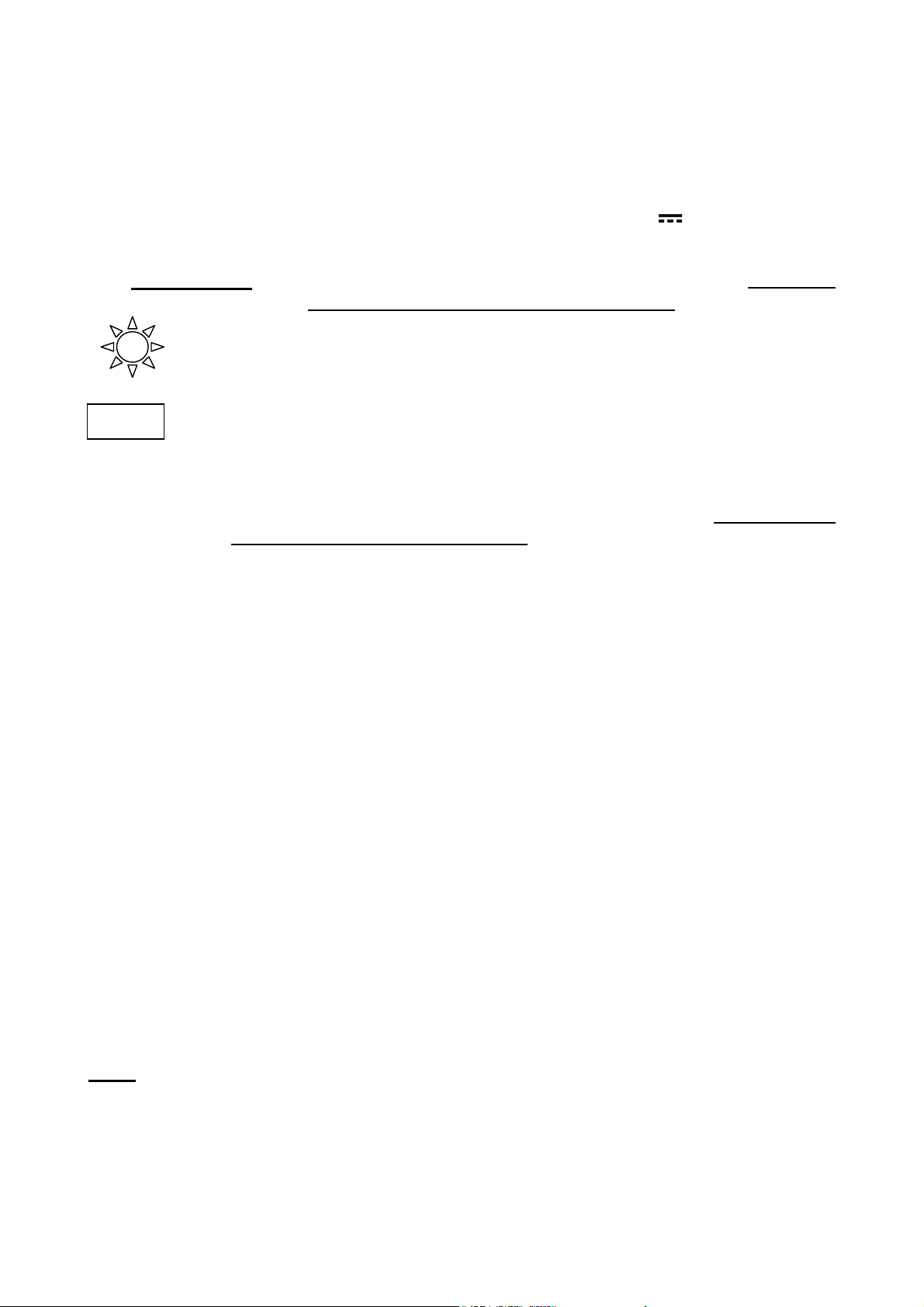
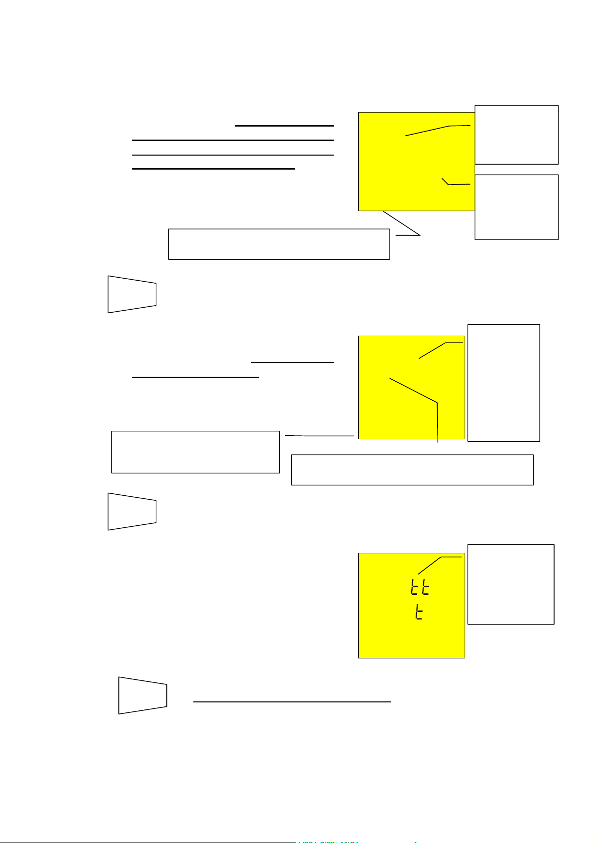
4.1 CANCELLATION OF CALIBRATION PARAMETERS
To cancel calibration parameters
(and the symbol CAL) it is
necessary to recalibrate the
instrument with a resistance
higher than 5Ω (for example with
disconnected test leads). When a
cancellation is made the screen
on the right is displayed first,
followed by the screen below:
The screen on the right is
displayed for 2 seconds, after
which the instrument emits a long
sound signal and then displays
the default screen relative to the
LOWΩ test under AUTO mode.
LOWΩ
o> 5 Ω
cal
Measuring
LOWΩ
es
cal
Message >5Ω:
means that the
instrument detected
a resistance higher
than 5Ω therefore it
will proceed with
Reset procedure.
Message rES:
means that the
instrument
cancelled the
calibration
parameter
(RESET) of the
calibration
parameters
8
Page 10
5. SWITCH POSITION FUNCTIONS:
5.1 “LOWΩ” POSITION
5.1.1 CONTINUITY TEST:
Continuity test of earth, protective and equalizing potential conductors with a test current
higher than 200 mA and open circuit voltage ranging from 4v TO 24v
o WARNING: Before carrying out the continuity test make sure that there is no
voltage at the ends of the conductor under test.
Turn the switch on LOWΩ position.
FUNC
Note:
If the resistance is lower than 16Ω (including the resistance of the calibration
results) the continuity test is made by the instrument with a current higher than
200mA. If the resistance is higher than 16Ω the continuity test is made by the
instrument using a current of 40mA.
The key FUNC permits to select one of the following measuring modes
(which can be shown cyclically when pressing this key):
Mode “AUTO” (the instrument carries out two measurements with
reversed polarity and displays their average value). This mode is
recommended for the continuity test.
Mode “R +” (measurement with positive polarity, black cable connected
to positive polarity and blue cable connected to negative polarity). This
mode can be used to evaluate the galvanic effect occurring at the ends
of the installation cable terminals (they are usually made of galvanised
iron) during the continuity test.
Mode “ R -“ (measurement with negative polarity, black cable connected
to negative polarity and blue cable connected to positive polarity). This
mode can be used to evaluate the galvanic effect occurring at the ends
of the installation cable terminals (they are usually made of galvanised
iron) during the continuity test reversing polarity with respect to the
previous mode (R+).
Mode “R + TIMER (measurement with positive polarity and possibility of
setting the duration time of the test). In this case the operator can set a
measuring time long enough to permit him to move the protective
conductors while the instrument is carrying out the test so detecting any
bad connection.
Mode “R - TIMER” (measurement with negative polarity and possibility of
setting the duration time of the test). In this case the operator can set a
measuring time long enough to permit him to move the protective
conductors while the instrument is carrying out the test so detecting any
bad connection.
Mode “CAL” (compensation of the resistance of the cables used for the
measurement).
9
Page 11
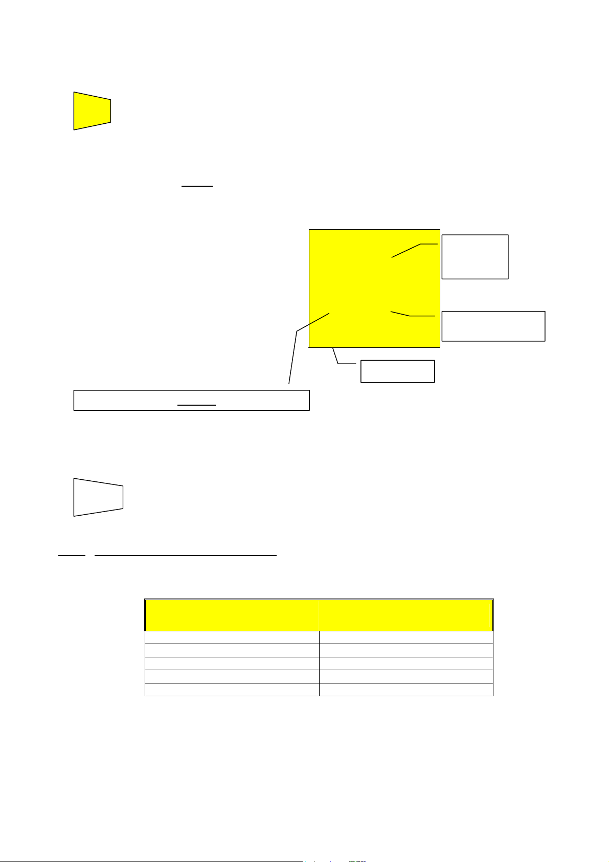
5.1.2 "AUTO", "R+", "R-", "R+TIMER", "R-TIMER" MODES:
1. Select the desired mode by means of the FUNC key.
2. Connect the black and blue cables to the instrument input terminals P and N
respectively.
Connection of the instrument terminals during LOWΩ test.
3. Connect two alligator clips to the test leads.
4. Short-circuit the measuring cable ends making sure that the conductive parts of the clips
make a good contact to each other. (See section 3.1.1) Press the GO key. If the
instrument displays a resistance value other than 0.00 repeat the instrument
calibration (see paragraph 4).
6. Connect the instrument terminals to the ends of the conductor on which the continuity test is
to be carried out (see previous picture).
7. If the mode "R+TIMER" or "R-TIMER" was selected use the following keys to select
the duration time of the test:
▲
▼
8. Press the GO key. The instrument effects the measurement.
GO
press this key to increase the duration time of the test (Tmax=15 seconds).
press this key to decrease the duration time of the test (Tmin=3 seconds).
In R+/R- Timer mode
press GO key again if the test is to be stopped.
o WARNING: The display of “Measuring” means that the instrument is
measuring and voltage is present. Never touch or disconnect
test leads during this phase.
10
Page 12
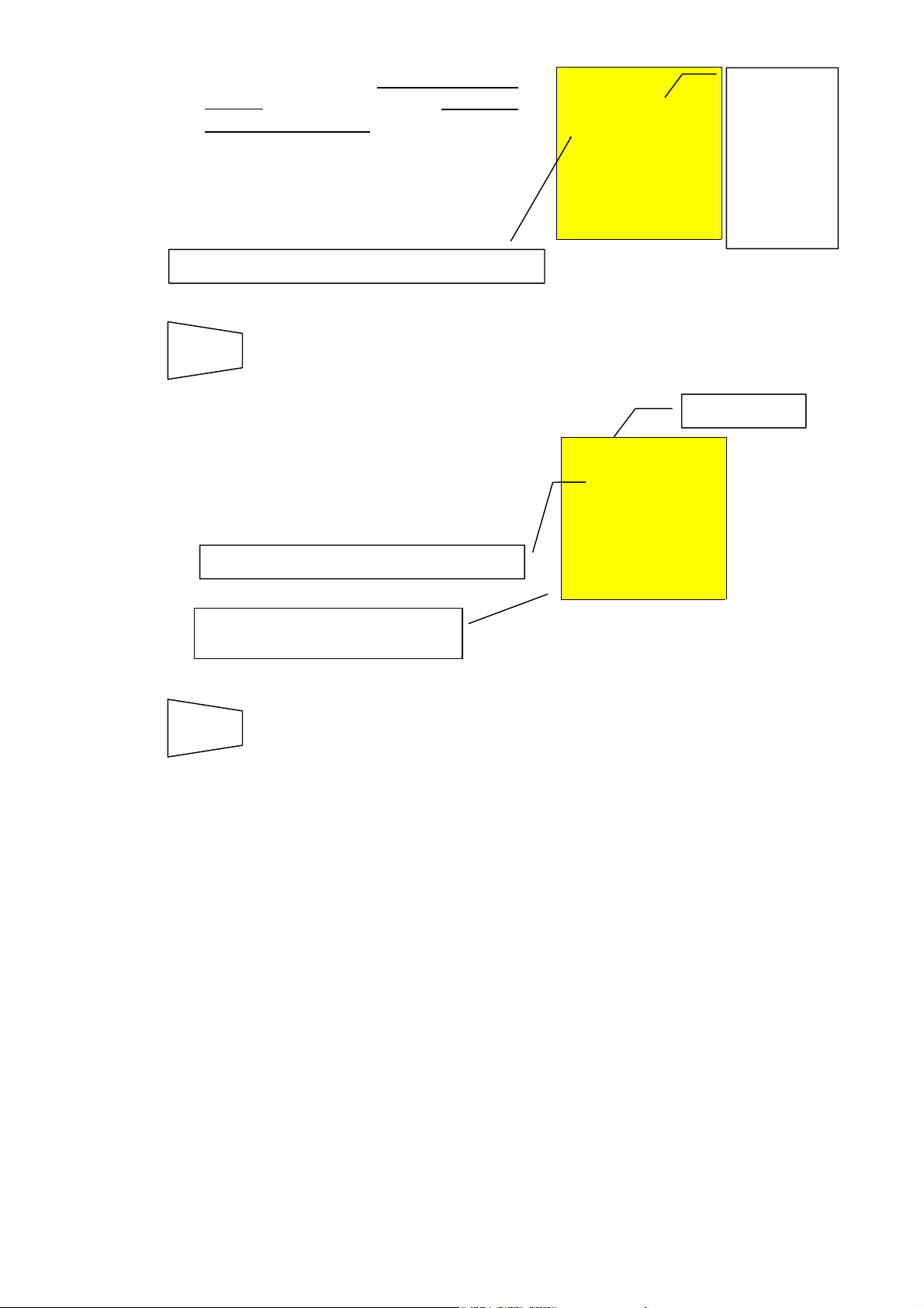
5.1.2.1 "AUTO" MODE
t
r
t
T
At the end of the test, if the average
resistance value Ravg results to be
lower than 5Ω
double sound signal indicating the
positive outcome of the test and
displays one screen similar to the
screen alongside.
SAVE
5.1.2.2 "R+" or “R-" MODE
At the end of the test if a resistance
value R+ or
R- lower than 5Ω was detected, the
instrument emits a double sound
signal indicating the positive
outcome of the test and displays
one screen similar to the screen
alongside.
SAVE
5.1.2.3 "R+TIMER" or “R-TIMER" MODE
At the end of the test if a resistance
value R+Timer or R–Timer lower
than 5Ω was detected, the instrument
(after the set time has elapsed) emits
a double sound signal indicating
the positive outcome of the test
displays one screen similar to the
screen alongside.
SAVE
The symbols R+ or R- are displayed.
The test can be stored by pressing the SAVE key twice (see paragraph 0).
the instrument emits a
The test can be stored pressing the SAVE key twice (according to
paragraph 0).
Either the symbol R+ or
the symbol R
The test can be stored pressing the SAVE key twice (according to
paragraph 0).
-.
CAL LOWΩ
1.07 Ω
219 mA
AUTO
CAL LOWΩ
1.07 Ω
219 mA
R+
R-
CAL LOWΩ
1.08 Ω
219 mA 5 s
R+
R-
IMER
Average
resistance
value Ravg.
Average tes
current value
Iavg.
Resistance
value R+ o
R-.
Value of tes
current I+ or I-.
Duration time of
the test.
Value of the
test current I+
or I-.
11
Page 13
5.1.2.4 ANOMALOUS CASES:
r
Ω
r
r
Anomalous cases which can occur during the following "AUTO", "R+", "R-", "R+TIMER",
"R-TIMER"
In case a value of Ravg or R+ or R-
higher than or equal to 5Ω but
lower than 99.9Ω (9.99Ω in
R+TIMER and R-TIMER) was
detected, at the end of the test the
instrument emits a long sound
signal displays one screen similar to
the screen alongside.
SAVE
In case one of the following modes
AUTO, R+, R- and a Ravg or R+ or
R- higher than 99.9Ω was selected,
at the end of the test the instrument
emits a long sound signal and
displays the screen alongside.
Selected mode (in the picture the
mode AUTO is indicated as
example).
SAVE
If the terminal voltage is higher than
10V, the instrument does not carry
out the test and displays the screen
alongside for 5 seconds after which,
the instrument displays the screen
relative to the precedent selected test
mode LOWΩ under AUTO mode.
Selected mode (in the picture the mode AUTO
is indicated as example).
The tests can be stored pressing the SAVE key twice (according to
paragraph 0).
ATTENTION: value of R
hi
gh.
The tests can be stored pressing the SAVE key twice (according to
paragraph 0).
CAL LOWΩ
o 5.75 Ω
216 mA 5s
AUTO
CAL LOWΩ
o> 99.9 Ω
- - - mA
AUTO
or R+ or R- is too
avg
CAL LOWΩ
o A
VOL AG
ATTENTION:
average value
of Ravg highe
than 5Ω.
Only in case
the mode
R+TIMER o
R-TIMER was
selected.
99.9Ω is the
maximum
value which
can be
measured in
the LOW
AUTO o
R+ or Rmode.
ATTENTION:
the test was
not made
Due to voltage
at the terminal
ends.
THIS RESULT CANNOT BE SAVED
SAVE
12
Page 14
A
In case the mode R+TIMER or RTIMER was selected and a R+ or R-
higher than 9.99Ω was detected, the
instrument emits an intermittent
sound signal during the test, a
long sound signal at the end of the
test and displays the screen
alongside.
ATTENTION: value of R+ or R- is too high.
SAVE
In case that:
R
MEASURED-RCALIBRATION
instrument displays the screen
alongside.
ATTENTION: R
Selected mode: (in this case
AUTO).
The tests can be stored pressing the SAVE key twice (see
paragraph 0).
< 0Ω the
MEASURED-RCALIBRATION
< 0 .
CAL LOWΩ
o> 9.99 Ω
TIMER
CAL LOWΩ
UTO
- - - mA 4 s
R+
o 0.00 Ω
219 mA
9.99Ω is the
maximum
value which
can be
measured in
LOWΩ,
R+TIMER
or R-TIME
mode.
blinking CAL.
R
SAVE
The tests can be stored pressing the SAVE key twice (according to
paragraph 0).
13
Page 15
5.2 “MΩ” POSITION
5.2.1 INSULATION RESISTANCE:
INSULATION RESISTANCE MEASUREMENT WITH TEST VOLTAGE OF 50V, 100V,
250V, 500V OR 1000V
o ATTENTION: Before making the insulation test make sure that the circuit
under test is not energised and all the relative loads are
disconnected.
Turn the switch on MΩ position.
FUNC
5.2.2 “MAN”, “AUTO”, “TIMER” MODES
The key FUNC permits to select one of the following measuring modes
(which can be shown cyclically when pressing the key):
Mode “MAN” (maximum test time of 10 seconds or set by the pressing
duration on the GO key). Recommended test.
Mode “AUTO” (the test ends when the measured value gets stable). This
test can be effected in case the installation has some capacities which
are to be charged in order to evaluate the real insulation resistance.
Mode “TIMER” (test duration depending on the selected interval (from 10
to 999 seconds). This test can be effected in case a minimum measuring
time is required.
Procedure to measure the insulation resistance valid for modes "MAN", "AUTO", "TIMER"
1. Select the desired mode by means of the FUNC key.
2. Connect the black and blue cables to the instrument input terminals P and N
respectively,
Example for the use of the instrument to check
insulation between phase and earth in an electrical
installation using untied cables.
Connection of the instrument terminals for MΩ test.
14
Page 16

3. Connect the test leads to the object which is to be tested after deactivating the
circuit to be tested and all the relative loads (see previous picture).
4. By means of U
5. If the mode "TIMER" was selected use the following keys to set the duration time of
U
n
the test:
▲
▼
carried out. The values to be selected are:
• 50V (test on telecommunications systems)
• 100V
• 250V
• 500V
• 1000V
press this key to increase the duration time of the test (Tmax=999 seconds).
press this key to decrease the duration time of the test (Tmin=10 seconds).
select the test voltage suitable for the type of test to be
n
o ATTENTION: If “Measuring” is displayed the instrument is taking the
measurement. During this phase do not disconnect the test
leads as the circuit under test may remain charged at a
dangerous voltage due to the parasite capacities of the
installation. Independently of the working mode selected the
instrument throws a resistance in the output terminals at the
end of each test to discharge the parasite capacities of the
circuit.
15
Page 17
5.2.2.1 "MAN" MODE
GO
At the end of the test, in case the
resistance value MΩ detected
results to be lower than R
(depending on the selected voltage
see following Table 4) and the test is
effected at the selected rated
voltage value, the instrument emits a
double sound signal indicating the
positive outcome of the test
displays one screen similar to the
screen alongside.
The values of measured resistance of isolation always must be confronted with the
normative limits (see Errore. L'origine riferimento non è stata trovata.) for being able to
assert if the system is to norm.
SAVE
Press the GO key.
The instrument effects the test lasting:
Maximum 10 seconds in case the key is pressed and released
within 5 seconds.
Until the key is released for all the other cases.
Note
: Press the GO key again if the test is to be stopped
Insulation
resistance
value R
ISO.
MAX
R
ISO
1.00 MΩ
500 V 20 s
MAN
Rated voltage value selected for the test.
The test can be stored pressing the SAVE key twice (according to
paragraph 0).
Test duration.
In this case the GO
key has been
pressed for 20
seconds.
Manual mode.
16
Page 18
5.2.2.2 "AUTO" MODE
r
GO
At the end of the test, in case the
resistance value MΩ detected
results to be lower than R
(depending on the selected voltage
see following Table 3), the test is
effected at the selected rated
voltage value and a stable value of
the resistance is detected, the
instrument emits a double sound
signal indicating the positive
outcome of the test displays one
screen similar to the screen
alongside.
SAVE
Press the GO key. The instrument effects the measurement ending
when the measured value gets stable.
Note
: Press the GO key again if the test is to be stopped
Rated voltage value selected for the test.
The test can be stored pressing the SAVE key twice (according to
paragraph 0).
MAX
R
ISO
1.18 MΩ
500 V 18 s
AUTO
Insulation
resistance
value R
Test duration.
In this case the
measurement
got stable afte
18 seconds.
Automatic mode.
ISO.
17
Page 19
5.2.2.3 "TIMER" MODE
GO
Press the GO key. The instrument effects the measurement ending
when the set time has elapsed.
999 seconds → Maximum value of the test duration.
10 seconds → Minimum value of the test duration.
Note:
Pressing the GO key again the test gets immediately
interrupted.
At the end of the test, in case the
resistance value MΩ detected
results to be lower than R
MAX
(depending on the selected voltage
R
ISO
2.07 MΩ
Insulation
resistance
value R
ISO.
see following Table 1) and the test is
effected at the selected rated
voltage value, the instrument emits a
double sound signal indicating the
positive outcome of the test
displays one screen similar to the
500 V 20 s
TIMER
Timer mode.
Duration of the set
test.
screen alongside.
Rated voltage value selected for the Timer test.
The values of measured resistance of isolation always must be confronted with the
normative limits for being able to assert if the system is to norm.
SAVE
The test can be stored pressing the SAVE key twice (according to
paragraph 0).
Note
The maximum resistance value R
which can be measured in mode MΩ
MAX
depends on the rated voltage selected for the test. In particular:
Rated voltage selected
for the test
50VDC
100VDC
250VDC
500VDC
1000VDC
R
= Maximum resistance
MAX
value
99.9MΩ
199.9MΩ
499MΩ
999MΩ
1999MΩ
Table1: Table of maximum resistance values which can be measured under MΩ
mode depending on the rated voltage selected.
18
Page 20
5.2.2.4 ANOMALOUS CASES:
f
f
Ω
Anomalous cases which may occur during the insulation tests "MAN", "AUTO", "TIMER"
The symbol ">" means that the resistance value R
In case a value of MΩ higher than
R
was detected (depending on the
MAX
selected voltage see following Note
Table, the instrument emits a double
sound signal at the end of the test
indicating the positive outcome of
the test and displays one screen
similar to the screen alongside.
Selected mode (MAN is indicated in the
picture).
is higher than R
ISO
.
MAX
R
ISO
> 999 MΩ
500 V 20 s
MAN
Test duration.
Maximum
resistance
value which
can be
measured
(999Ω is
displayed i
a rated
voltage o
500V was
selected
see Table).
The test can be stored pressing the SAVE key twice (according to
SAVE
paragraph 0).
In case a test is taken at a voltage
R
ISO
lower than the set rated voltage, at
the end of the test the instrument
o0.01 MΩ
emits a long sound signal and
displays one screen similar to the
screen alongside.
ATTENTION: the test of resistance M
voltage value lower than the set rated voltage. Low
insulation case. This case occurs under low insulation
conditions or in the presence of capacity on the
installation.
was taken at a
500 V 20 s
MAN
Selected mode (MAN is
indicated in the picture).
The tests can be stored pressing the SAVE key twice (according to
SAVE
paragraph 0).
19
Page 21
If the terminal voltage is higher than
30V, the instrument will not take the
test, displays the screen alongside for
5 seconds after which, it shows the
default screen relative to the MΩ test
under AUTO mode.
R
ISO
o A
VOL AG
ATTENTION:
the test was not
carried out.
Check that the
circuit is not
energised.
SAVE
SAVE
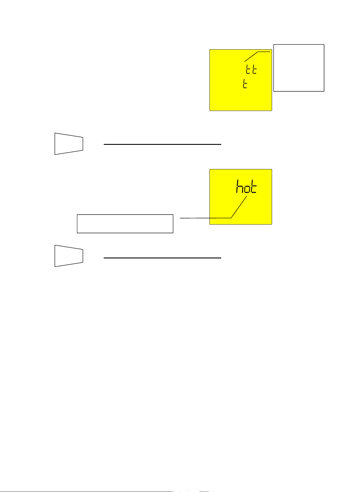
If the instrument gets overheated,
tests cannot be carried out and the
message alongside is displayed. Wait
until the initial screen is back in order
to proceed with measurements.
Message “hot”:
the instrument got overheated.
THIS RESULT CANNOT BE SAVED.
THIS RESULT CANNOT BE SAVED.
R
ISO
o
20
Page 22
5.3 HOW TO SAVE, RECALL AND CLEAR TEST DATA
the
easurement results
stored
easurement to be saved
5.3.1 SAVE
If the results relative to the tests effected are to be stored you can proceed as follows:
1. Press the SAVE key once.
SAVE
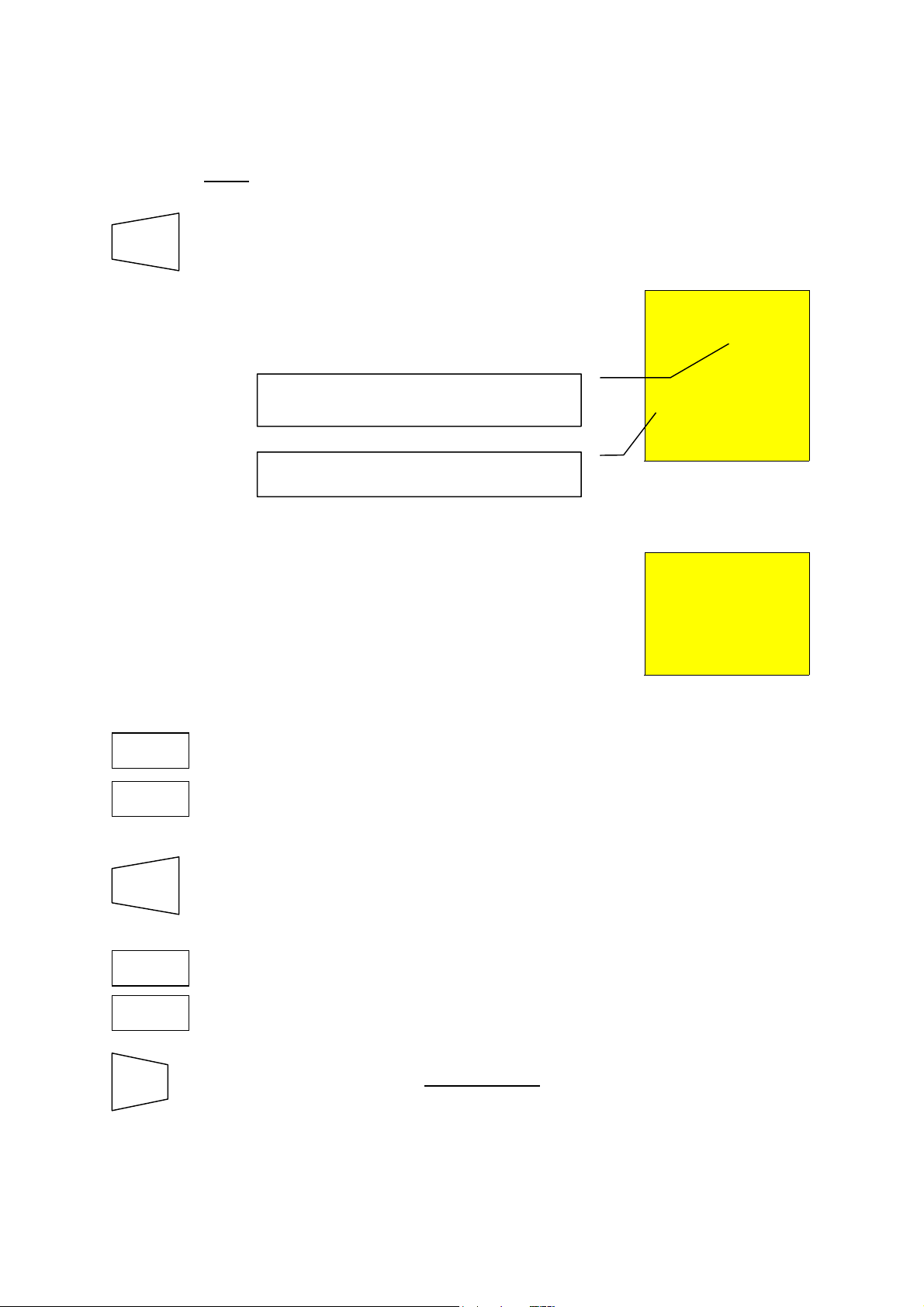
If the memory of the instrument is not
empty it displays the screen to the
right.
Number of the memory location in which
m
Value of the parameter P related to the
m
If the test cannot be saved the
instrument displays the screen on the
right.
will be
.
.
MEM
3
P02
MEM
o
2. Use the keys ▼, ▲ to increase or decrease the value of the parameter
3. Press the SAVE key again, the instrument emits two sound signals,
▼
▲
SAVE
ESC
P to be related to the measurement which is to be saved. This
parameter helps the operator to classify the tests effected.
Example: if the tests are to be carried out in a building, the operator
can associate the measurements effected in a room with
a given value of the parameter P. In this way different
value of the parameter P will correspond to different
rooms.
confirming that the test results have been stored.
Press the ESC key in any moment
management mode and go back to the selected measuring function.
you want to quit the memory
21
Page 23
5.3.2 RECALL
saved measurement
If you want to recall the stored test results proceed as follows:
1. Press the RCL key.
RCL
If the memory of the instrument is not
empty it displays the screen
alongside.
Number of the memory location in which
the measurement results were stored.
Value of the parameter P related to the
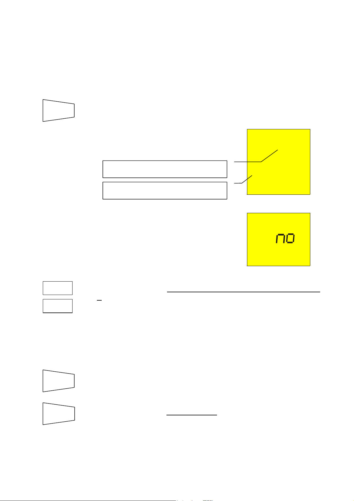
If the memory of the instrument is
empty it displays the screen
alongside.
.
MEM
3
P02
Riso
o
no rcl
2. Use the keys ▼, ▲ to select the memory location number to be
3. Press the DISP key to display the test result related to the selected
4. Use the keys ▼, ▲ again if you want to display again the numbers of
▼
▲
DISP
▼
▲
ESC
displayed.
memory location.
memory locations.
Press the ESC key at any point
management mode and go back to the selected measuring function.
you want to quit the memory
22
Page 24
5.3.3 CLEAR
the
easurement results were stored
saved measurement
If you want to cancel the stored tests results proceed as follows:
1. Press the RCL key. The instrument displays a screen like the
RCL
following:
MEM
Number of the memory location in which
m
Value of the parameter P related to the
.
2. Use the keys ▼, ▲ to select the number of the memory location.
3. Press the DISP key to display the test result related to the memory
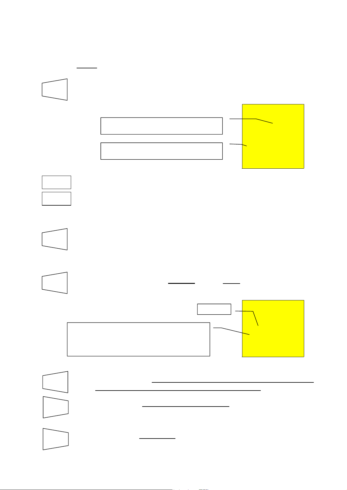
4. Press CLR once. The blinking
▼
▲
DISP
CLR
ATTENTION: the instrument will cancel all the results stored from the
memory location selected to the last memory location
full.
location selected. In case that a few results were stored in the memory
location (Ex: RCD test under AUTO mode) it is necessary to press
DISP more than once to display them.
face two possibilities:
.
P02
symbol "clr" is displayed. Now you
Blinking.
MEM
3
clr
The instrument cancels the memory cells from n.2
to n.8, where n.2 is the one selected by the
operator while n.8 is the last test saved in the
instrument.
p 08
CLR
ESC
ESC
Press CLR again if the tests selected are to be cancelled starting
from the one selected down to the last one saved.
Press ESC to nullify the clearing phase. The blinking symbol "clr"
disappears.
Press the ESC key at any point
mode and return to the selected measurement function.
if you want to quit the memory management
23
Page 25
Example: 97 tests have been stored in the instrument.
If you want to cancel the tests from 43rd to 97
- Press RCL.
- Select with keys ▼, ▲ the memory location 43.
- Press CLR. You can see CLR blinking on the primary display, 43 on the
left secondary display and 97 on the righ secondary display.
- Press CLR. The tests from 43 to 97 has cancelled.
th
, you proceed as follows:
5.4 RESET PROCEDURE
Reset of the INSTRUMENT and default parameters
Press DISP, CLR, RCL at the same time the rotary switch is turned on.
The screen nearby is displayed
for 5 seconds, after which the
instrument emits a sound signal
and then displays the screen
relative to the function selected
with the rotary switch.
rES
ATTENTION: the reset procedure will erase all the stored tests and it will set the default
parameters in the instrument.
Before conducting a reset procedure, download the stored tests on a PC.
5.5 DEFAULT PARAMETERS
Ω
5.5.1 DEFAULT PARAMETERS LOW
Parameter Reset default parameter
Mode AUTO
Calibration Offset 0 (CAL off)
Mode R+/R- TIMER Timer 3s
5.5.2 DEFAULT PARAMETERS MΩ
Parameter Reset default parameter
Mode MAN
Test voltage 500V
Mode TIMER Timer 60s
5.5.3 MEMORY DEFAULT PARAMETERS
Parameter Reset default parameter
Parameter P P = 1
Memory state 1(empty)
24
Page 26
6. PRACTICAL EXAMPLES OF ELECTRICAL TESTS
r
t
r
r
r
r
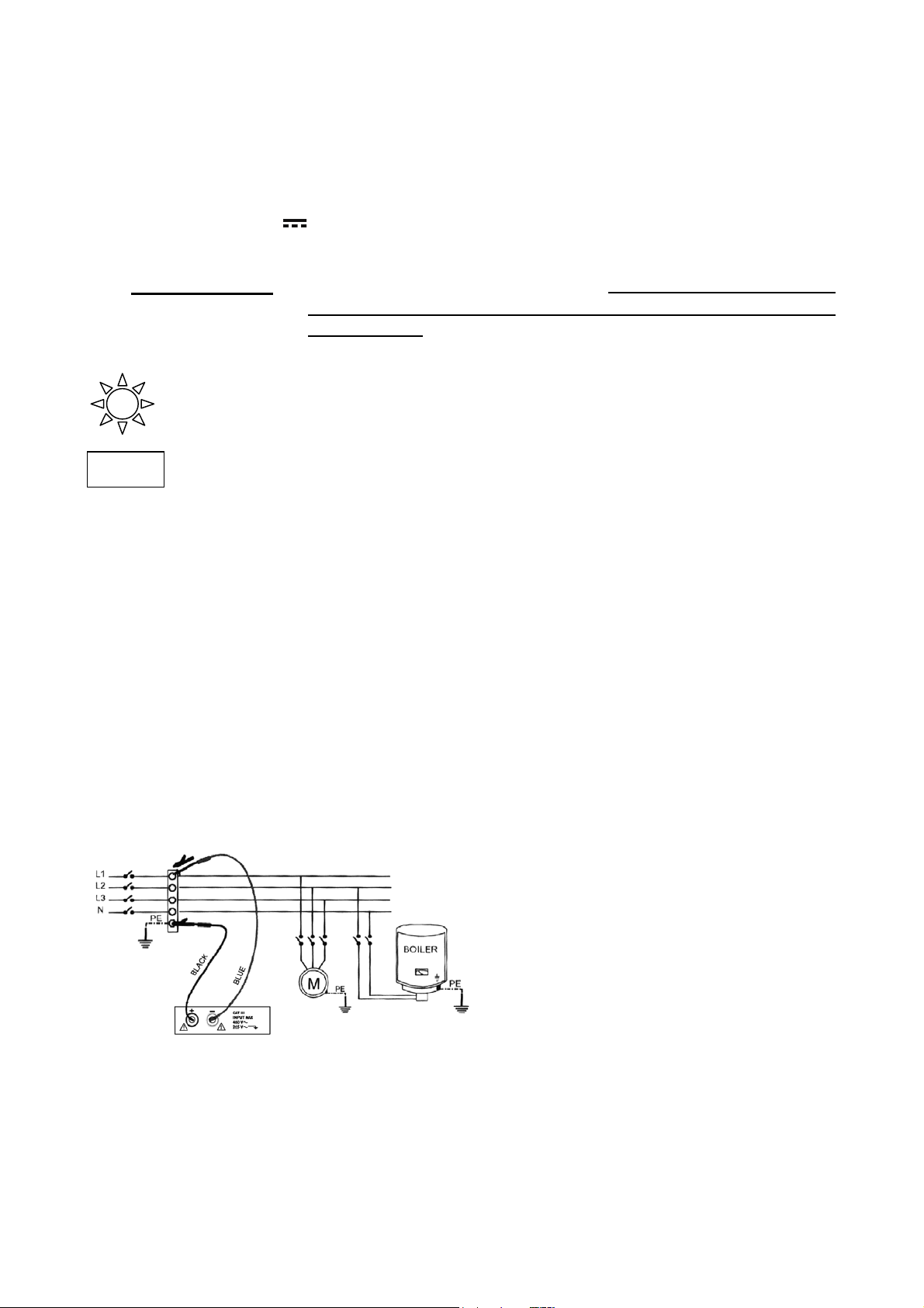
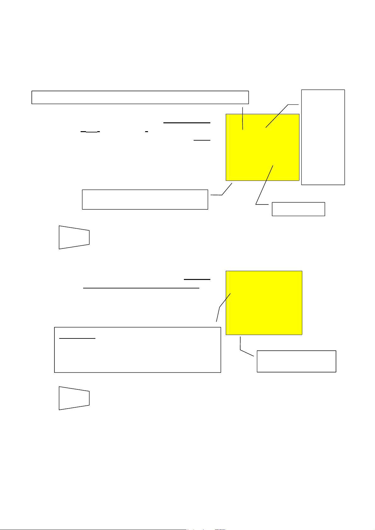
6.1 LOW CONTINUITY MEASUREMENT
CONTINUITY MEASUREMENT ON PROTECTIVE CONDUCTORS
PURPOSE OF THE TEST
Check the continuity of: protective conductors (PE), main equalising potential
conductors (EQP), secondary equalising potential
conductors (EQS) in TT and TN-S systems.
neutral conductors having functions of protective
conductors (PEN) in TN-C system.
NOTE: This test is to be preceded by a visual check verifying the existence of yellow-
green protective and equalising potential conductors as well as compliance of
the sections used with the standards’ requirements.
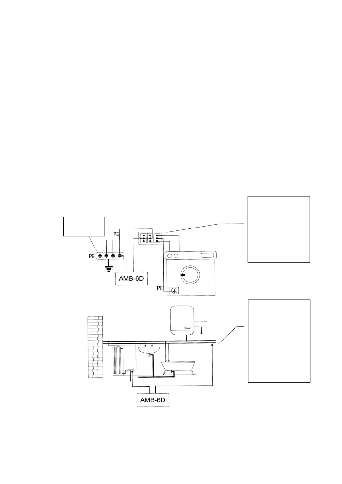
INSTALLATION PARTS TO BE CHECKED.
Equalising
potential node
Connect one of the
test leads to the
protective conducto
of the FM socke
and the other to the
equalising potential
node of the earth
installation.
Connect one of the
test lead to the
external mass (in
this case the wate
pipe) and the othe
to the earth
installation using fo
example the
protective conducto
of the closest FM
socket.
Examples for continuity measurement on conductors
25
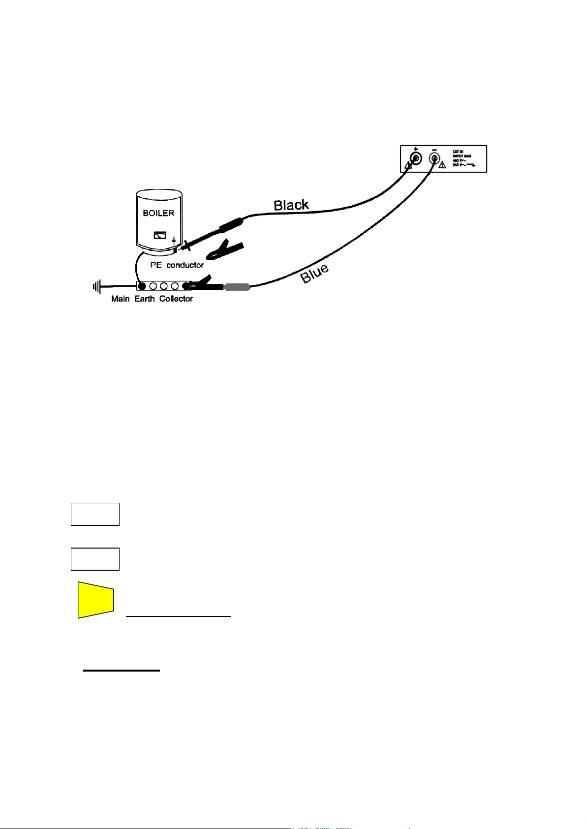
Page 27

Check the continuity among:
a) earth poles of all the plugs and earth collector or node.
b) earth terminals of class I instruments (Boiler etc.) and earth collector or node.
c) main external masses (water, gas pipes etc.) and earth collector or node.
d) auxiliary external masses to the earth terminal.
ALLOWABLE VALUES
The standards CEI 64-8/6 do not give any indication on the maximum resistance values
which cannot be overcome, in order to be able to declare the positive outcome of the
continuity test.
The standard CEI 64-8/6 simply requires that the instrument in use warns the operator if
the test was not carried out with a current of at least 0.2 A and an open circuit
voltage ranging from 4 V to 24 V.
The resistance values can be calculated according to the sections and lengths of the
conductors under test, anyway if the instrument detects values of some ohm the test
can be considered as passed.
6.2 INSTALLATION RESISTANCE
INSTALLATION RESISTANCE MEASUREMENT OF ELECTRICAL INSTALLATIONS
(250VDC, 500VDC, 1000VDC)
PURPOSE OF THE TEST
Check that the insulation resistance of the installation complies with the requirements
of standards CEI 64-8/6.
NOTE: This test is to be made on an open circuit with any load disconnected.
INSTALLATION PARTS TO BE CHECKED
a) Between each active conductor and the earth (the neutral conductor is considered
an active conductor except in the case of TN-C systems where it is considered
part of the earth (PEN).
During this measurement all active conductors can
case the measurement result does not fall within the standard limits the test is to be
repeated for each single conductor.
b) Among active conductors
The standard CEI 64-8/6 recommends to check the insulation among the active
conductors when this is possible (ATTENTION)
.
be connected to each other, in
.
26
Page 28
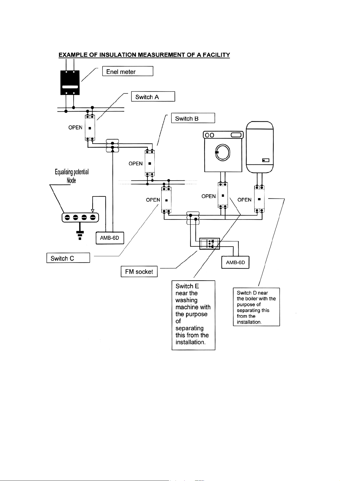
Insulation measurements in a facility.
A procedure indicating how to take the insulation resistance measurement of a facility is
reported in the following table:
27
Page 29
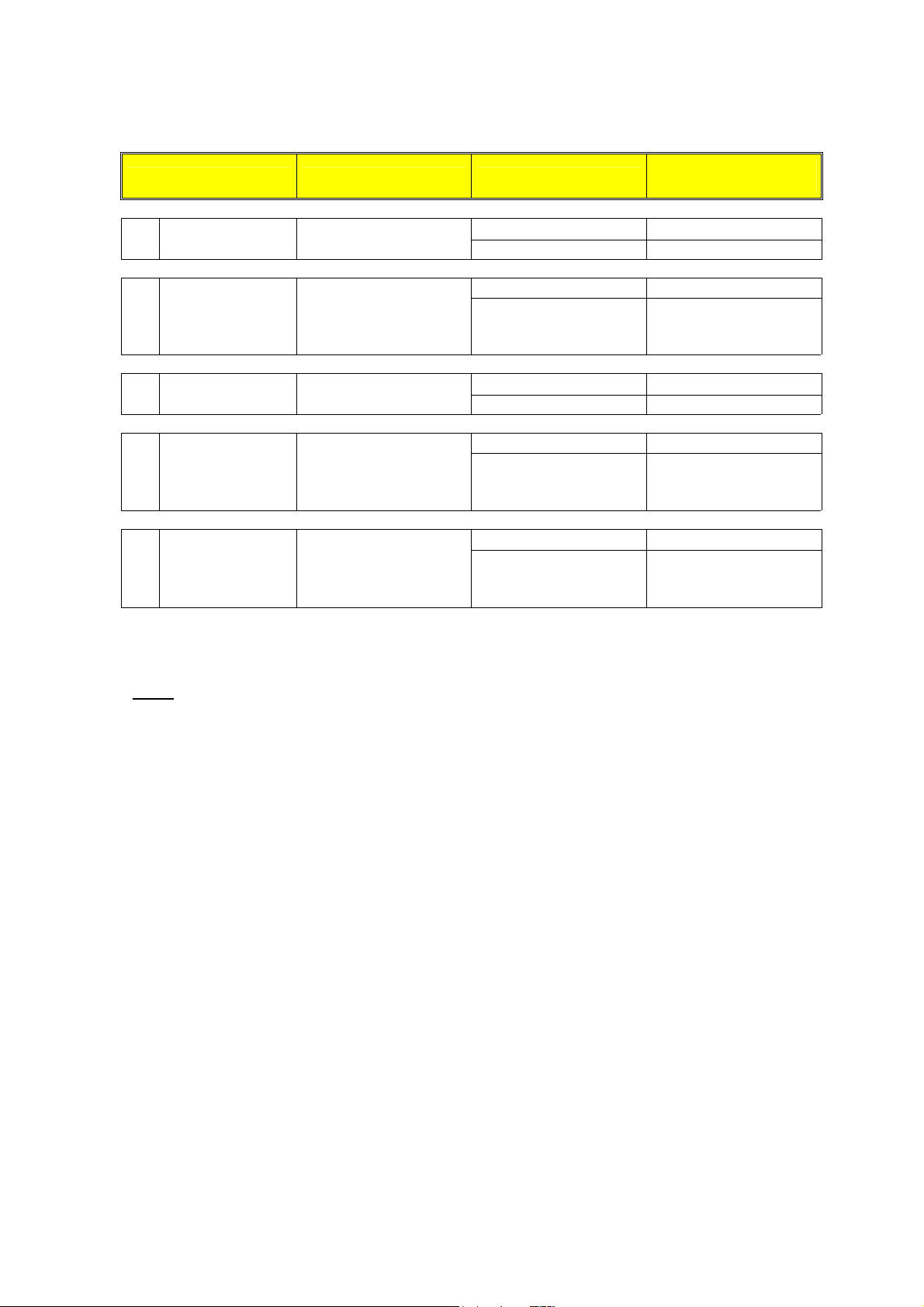
Procedure for insulation resistance measurement referring to the previous picture:
Switch situation Point under test Measurement result
Turn the switch A,
1
2
3
4
5
l D and E off
Turn the switch B
off
Turn the switch C
off
Take the measurement
on switch A
Take the measurement
on switch A
Take the measurement
on switch B
Take the measurement
on switch B
Take the measurement
on switch C
Se R ≥ R
Se R< R
Se R ≥ R
Se R< R
Se R ≥ R
Se R< R
Se R ≥ R
Se R< R
Se R ≥ R
Se R< R
LIMITE
LIMITE
LIMITE
LIMITE
LIMITE
LIMITE
LIMITE
LIMITE
LIMITE
LIMITE
Judgement of an
installation
☺ OK (end of the test)
Proceed 2
Proceed 3
INSTALLATION
NOT COMPLYING
WITH STANDARDS
☺ OK (end of the test)
Proceed 4
Proceed 5
INSTALLATION
NOT COMPLYING
WITH STANDARDS
☺ OK (end of the test)
INSTALLATION
NOT COMPLYING
WITH STANDARDS
Table1: Table with procedure steps for insulation measurement referred to the
installation reported in Errore. L'origine riferimento non è stata trovata.
Note The switches D and E are those installed near the load having the purpose of
separating it from the installation. In case the above said RCDs do not exist it is
necessary to disconnect the users from the before making the insulation resistance
test.
ATTENTION:
If the installation includes electronic devices, disconnect them from the installation and
in case this is impossible only the test "a" is to be effected, that is to say between
active conductors (which in this case SHALL be connected together) and the earth.
28
Page 30
ALLOWABLE VALUES
The values of test voltage and minimum insulation resistance are reported in the
following table (CEI64-8/6 Tab. 61A):
Rated circuit voltage
(V)
SELV and PELV* 250 ###0.250
Up to 500 V included, except for the
above circuits.
Over 500 V 1000 ###1.000
* In the new standards the terms SELV and PELV replace the old definitions
"safety low voltage" or "functional".
Table2: Table summarising the test voltage values and relative limit values for
the most common kinds of test.
NOTE:
If the circuit is quite large the conductors running side by side make up a capacity
which is to be charged by the instrument in order to carry out a correct
measurement; in this case it is recommended to keep the GO key pressed (in case
a test is made under manual mode) until the result gets stable.
ATTENTION: When you take measurements among active conductors it is
essential to disconnect all the users (alarm lamps, intercom transformers, boilers
etc) otherwise the instrument will measure their resistance instead of the installation
insulation. Moreover any insulation resistance test among active conductors could
damage them.
The indication "> 1999MΩ" or “o.r.” (out of range) warns that the insulation resistance
measured by the instrument is higher than the maximum resistance limit (see technical
specifications); this result is obviously far higher than the minimum limits of the above
table therefore if during a test this symbol is displayed the insulation of that point is to be
considered in compliance with standards.
Test voltage
(V)
500 ###0.500
Insulation resistance
(M###)
29
Page 31

6.3 CHECKING THE CIRCUIT SEPARATION
PURPOSE OF THE TEST
The test, to be made in case the protection is realised through separation (64-8/6 612.4,
SELV or PELV or electrical separation), shall check that the insulation resistance
measured according to the indications below (depending on the separation type)
complies with the limits reported in the table relative to the insulation measurements.
INSTALLATION PARTS TO BE CHECKED
• SELV system (Safety Extra Low Voltage):
measure the resistance between the active parts of the circuit under test
(separate) and the active parts of the other circuits.
measure the resistance between the active parts of the circuit under test
(separate) and the earth.
The resistance shall not be lower than 0.25MΩ with a test voltage of 250VDC.
• PELV system (Protective Extra Low Voltage):
measure the resistance between the active parts of the circuit under test
(separate) and the active parts of the other circuits.
The resistance shall not be lower than 0.25MΩ with a test voltage of 250VDC.
• Electrical separation:
measure the resistance between the active parts of the circuit under test
(separate) and the active parts of the other circuits.
measure the resistance between the active parts of the circuit under test
(separate) and the earth.
The resistance shall not be lower than 0.5MΩ with a test voltage of 500VDC and
1MΩ with a test voltage of 1000VDC.
30
Page 32

r
r
t
r
t
EXAMPLE OF CHECKING THE SEPARATION AMONG ELECTRICAL CIRCUITS
Transformer
TEST AMONG
THE ACTIVE
PARTS.
Connect a test
lead of the
instrument to
Between the active
parts of the
separated circui
and among those
other circuits
one of the two
conductors of the
secondary circui
and the othe
test lead to one
of the conductors
of a primary
circuit.
Equalizing
potential
Earth
TEST
BETWEEN
THE ACTIVE
PARTS AND
THE EARTH.
Connect a test
lead of the
instrument to
one of the two
conductors of the
secondary circuit
and the othe
one to the
equalizing
potential node.
This test is to be
made only on
SELV circuits o
with electrical
separation.
31
Page 33

ALLOWABLE VALUES
The test result is positive when the insulation resistance indicates values higher or
equal to those indicated in the table reported in the section relative to insulation tests.
Notes:
• SELV system: is a system of category zero or very low safety voltage featured by:
• PELV
• Electrical separation
Power supply: autonomous source (ex. batteries, small generator) or safety (ex.
safety transformer).
Protection separation to other electrical systems (double or reinforced insulation or
a metal screen connected to the earth).
There are no earth points (insulated from the earth).
system: is a system of category zero or very low safety voltage featured by:
Power supply: autonomous source (ex. batteries, small generator) or safety (ex.
safety transformer).
Protection separation to other electrical systems (double or reinforced insulation or
a metal screen connected to the earth).
There are earthed points (not insulated from the earth).
: is a system featured by:
Power supply: insulation transformer or autonomous source with equivalent
features (ex. generator).
Protection separation to other electrical systems (insulation not lower than that of
the insulation transformer).
Protection separation to the earth (insulation not lower than that of the insulation
transformer).
6.4 MEASUREMENT OF FLOOR INSULATION RESISTANCE IN
MEDICAL ROOMS CEI 64-4
PURPOSE OF THE TEST
Check that the floor is made of material whose insulation resistance complies with the
requirements of the standards CEI 64-4 (3.05.03).
INSTALLATION PARTS TO BE CHECKED
The test shall be taken between:
a) Two electrodes whose distance to each other shall be one meter.
b) One electrode on the floor and the equalising potential node.
32
Page 34

Test b) :
Connect the
instrument test
leads to the
electrodes placed
on the floor at a
reciprocal
distance of one
meter
Equalizing potential node
Test b):
Connect one test lead
of the instrument to the
equalizing potential
node and the other to
one of the electrodes
placed on the floor at
distance higher than
one-meter way from
earthen objects.
Measurements of floor insulation resistance in medical rooms
The electrodes shall consist of a plate having a surface of 3 square inches (20 cm
weight equal to approx. 2.2 lbs. (1 Kg) , and a humid absorbing paper (or humid thin
cotton cloth) with the same surface placed between the metal plate and the floor.
The insulation resistance is represented, both for the measurements indicated in "a"
and for the measurements indicated in "b", by the average of 5 or more tests taken
in different positions at a distance higher than 1 m away from earthed objects.
ALLOWABLE VALUES
The maximum values of the calculated resistance are the following:
- 1 M# for measurements taken on a ## new floor.
- 100 M# for the periodical tests taken ## after the first year
as from the floor
realisation and for the periodical check every 4 years.
All the values shall be registered on a protocol of the initial tests (64-4 5.1.02) and, for
the periodical controls, on the register of periodical tests (64-4 5.2.02).
33
2)
,
Page 35

7. CONNECTING INSTRUMENT TO PC
The connection between PC and instrument is realised through the serial port and optical
serial cable, provided with the software package "SUPERLINK".
Before making the connection it is necessary to select the COM port used for the
transmission. To set this parameter, start "SUPERLINK" and look in the help menu.
o ATTENTION: The selected port shall NOT be shared by other devices or
applications (example mouse, modem, etc.).
To transfer the stored data from the instrument to the PC keep to the following procedure:
1. Turn the switch on position RS232.
FUNC
2. By means of the FUNC key select the mode "Ser":
Then proceed according to the software instruction manual to transfer
the measurements effected.
The communication between
instrument and PC occurs by means
of the SUPERLINK software.
Transmission speed to be set in the
software (see Options, System
parameters): 9600 baud.
SEr
34
Page 36

f
8. PRINTING OF DATA ON SERIAL PRINTER (OPTIONAL)
( NOT AVAILABLE through Amprobe)
The connection between printer and instrument is realised through the serial port and
optical serial cable, provided with the printer (optional). Available
To transfer the stored data from the instrument to the printer keep to the following
procedure:
1. Turn the switch on RS232 position.
FUNC
2. By means of the FUNC key select the modes "Prn ALL n" or "Prn n1
n2", to respectively display the following screens:
Prn
ALL n
Press GO to start printing of all
the stored test results.
Press ESC to stop printing
immediately.
Prn
All 125
n1=13 indicates the memory cell which will be printed
as the first one.
Note
Transmission speed to be set on the printer: 4800 baud (see manual enclosed to
the printer).
Prn
n=125 indicates the maximum number o
stored measurements.
n1 n2
Press GO to start printing
of the test results from
number n1 to number n2
inside the memory ordered
under the increasing value
of the parameter P.
Press ESC to stop printing
immediately.
n2=25 indicates the memory
cell which will be printed as
the last one.
Prn
13
25
35
Page 37

9. MAINTENANCE
9.1 GENERAL
1. The tester you have purchased is a precision instrument. Strictly follow the instructions
for use and storage reported in this manual to avoid any possible damage or danger
during use.
2. Do not use this tester under unfavourable conditions of high temperature or humidity.
3. Do not expose to direct sunlight.
4. If the instrument is not to be used for a long period please remove the batteries to
avoid acid leakage which may damage the internal circuits of the instrument.
9.2 BATTERY REPLACEMENT
When the symbol
NOTE
: The instrument is capable of keeping the data stored
even though batteries are not installed.
is displayed batteries are to be replaced.
o ATTENTION: Before replacing batteries make sure that all test leads have been
disconnected from input terminals.
1. Switch OFF the instrument.
2. Remove all the test leads from the input terminals.
3. Unscrew the screw from the battery compartment cover and remove it.
4. Remove all batteries replacing them with 6 new ones of the same type (1.5V AA
alkaline) observing the polarity signs.
5. Replace the battery compartment cover.
9.3 INSTRUMENT CLEANING
Use a soft dry cloth to clean the instrument. Never use wet cloths, solvents, water, etc.
36
Page 38

10. TECHNICAL SPECIFICATIONS
TECHNICAL FEATURES
Accuracy is indicated as [% of reading + number of digits]. It refers to the following
atmospheric conditions: a temperature of 23°C ± 5°C with a relative humidity < 75%.
Continuity
Test mode
AUTO, R+, R-
R+TIMER
R-TIMER
Measuring range
(Ω)
0.01 – 19.99 0.01
20.0 – 99.9 0.1
0.01 – 9.99 0.01
Test current >200mA DC up to 16Ω (incluse the resistance of the calibration)
40mA DC from 16Ω to 99.9Ω
Test current resolution 1mA
Open circuit Test Voltage 9V
Insulation resistance
Test voltage
(Ω)
50
100
250
500
1000
Measuring range
(MΩ)
0.01 – 19.99 0.01
20.0 – 49.9 0.1
50.0 – 99.9 0.1
0.01 – 19.99 0.01
20.0 – 99.9 0.1
100.0 – 199.9 0.1
0.01 – 19.99 0.01
20.0 – 199.9 0.1
200 - 249 1
250 - 499 1
0.01 – 19.99 0.01
20.0 – 199.9 0.1
200 - 499 1
500 - 999 1
0.01 – 19.99 0.01
20.0 – 199.9 0.1
200 - 999 1
1000 - 1999 1
Automatic selection of the measuring range
Open circuit voltage 1,1 x Rated voltage test
Short circuit current <3,0mA - 500V
<2,0mA - 50V, 100V, 250V, 1000V
Rated measuring current 2,17 mA - 500V/230kΩ
1mA - 1000V/1MΩ
If the instrument measures a voltage higher than 30V, the instrument will not take a
measurement.
Safety standards
Insulation: Class 2, double insulation
Over voltage category: CAT III
Resolution
(Ω)
Resolution
(Ω)
Accuracy
±(2% Reading + 2 digit)
±(2% Reading + 2 digit)
Accuracy
±(2% Reading + 2 digit)
±(5% Reading + 2 digit)
±(2% Reading + 2 digit)
±(5% Reading + 2 digit)
±(2% Reading + 2 digit)
±(5% Reading + 2 digit)
±(2% Reading + 2 digit)
±(5% Reading + 2 digit)
±(2% Reading + 2 digit)
±(5% Reading + 2 digit)
37
Page 39

General specifications
Mechanical features
Dimensions: 222(L) x 162(La) x 57(H)mm
Weight (batteries included): approx. 1000g
Power supply
Battery type: 6 each 1.5V “AA” batteries
Low battery indication: The symbol
voltage is too low.
Battery life: About 40 hours in stand-by or
500 LowΩ tests or
250 MΩ tests 500V/500kΩ or
1000 LOOP or RCD or PHASE SEQUENCE
Automatic Turn Off Turns off after 5 minutes without use.
Display
Features: LCD custom.
Memory: 350 tests
Interface optical RS232 to print or to download the tests
Environment
Environmental working conditions
Reference temperature: 73° F (23°C)
Working temperature: 14 -140°F (-10 - 50 °C)
Relative humidity allowed: <80%
Storage temperature: 68 - 140°F (-20 - 60 °C)
Storage humidity: <70%
EMC
This instrument was designed in compliance with the EMC standards in force and its
compatibility was tested relating to:
Radiated emissions: EN55011
Immunity: EN50140, EN 61000
Electrostatic discharges: EN61000-4-2
R.F. field: EN50140
Fast transient: EN61000-4-4
is displayed when the battery
This instrument complies with the requirements of the European Low Voltage
Directives 72/23/CEE and CEM 89/336/CEE, amended with 93/68/CEE.
38
Page 40

STANDARD EQUIPMENT
The package contains:
• The instrument
• Carrying Case
• Owner’s Manual
• Test Leads Set (includes: two leads with alligator clips and one test probe)
• Optical Download Cable
• CD-ROM with “SUPERLINK” software for downloading/reading measurements
REPLACEMENT PARTS
Part Description
Carrying Case GP-2CC
Optical Download Cable C-2000
Test Leads Set (complete set w/ cables, alligator clips & probe) MT1-LEADS
Part #
39
Page 41

11. WARRANTY AND SERVICE CONDITIONS
LIMITED WARRANTY
Congratulations! You are now the owner of an AMPROBE
instrument. It has been quality crafted according to
quality standards and contains quality components and
workmanship. This instrument has been inspected for
proper operation of all of its functions. It has been
tested by qualified factory technicians according to the
long -established standards of AMPROBE INSTRUMENT.
Your AMPROBE instrument has a limited warranty against
defective materials and/or workmanship for one year from
the date of purchase provided that, in the opinion of
the factory, the instrument has not been tampered with
or taken apart.
Should your instrument fail due to defective materials,
and/or workmanship during the two-year period, please
have your dated bill of sale which must identify the
instrument model number and serial number and call the
number listed below:
Service Division
AMPROBE INSTRUMENT
Miami, Florida 33150
Tel: 800-327-5060
Outside the U.S.A. the local Amprobe representative will
assist you. Above limited warranty covers repair and
replacement of instrument only and no other obligation
is stated or implied.
SERVICE
If the instrument fails to operate, check battery, test
leads, etc and replace as necessary. If the instrument
still malfunctions, please call the phone number listed
below:
---------------------------Service Division
AMPROBE INSTRUMENT
Miami, Florida 33150
Tel: 800-327-5060
Outside the U.S.A. the local Amprobe representative will Assist you.
40
Page 42

Miami, FL 33150
(305) 423-7500
(800) 327-5060
Page 43

Copyright Amprobe 2003
Manual de Instrucciones
MultiTest 1000
Page 44

Page 45

AMPROBE
MULTITEST1000
Indice:
1. PRECAUCIONES Y MEDIDAS DE SEGURIDAD ......................................................3
1.1. INSTRUCCIONES PRELIMINARES .................................................................................3
1.2. DURANTE EL USO ...........................................................................................................4
1.3. DESPUES DEL USO.........................................................................................................4
2. DESCRIPCION GENERAL.........................................................................................5
2.1. FUNCIONES......................................................................................................................5
2.2. DESCRIPCION DEL INSTRUMENTO ..............................................................................6
3. PREPARACION PARA EL USO ................................................................................7
3.1. CONTROLES INICIALES..................................................................................................7
3.2. ALIMENTACION DEL INSTRUMENTO ............................................................................7
3.3. CALIBRACION ..................................................................................................................7
3.4. ALMACENAMIENTO .........................................................................................................7
3.5. SELECCIÓN DE IDIOMA Y UNIDAD DE MEDIDA ...........................................................8
4. DESCRIPCION DEL CONMUTADOR DE FUNCIONES............................................9
4.1. LOWΩ: PRUEBA CONTINUIDAD DE CONDUCTORES DE PROTEC Y EQUIP. ...........9
4.1.1. MODALIDAD "CAL".......................................................................................................................10
4.1.2. P
4.1.3. S
ROCEDIMIENTO DE MEDIDA PARA LA CONTINUIDAD DE LOS CONDUCTORES EQUIPOTENCIALES
MODALIDAD
ITUACIONES ANOMALAS EN LAS PRUEBAS "AUTO", "R+TIMER", "R-TIMER" ..............................14
"AUTO", "R+TIMER", "R-TIMER" ...........................................................................12
4.2. MΩ: MEDIDA DE LA RESISTENCIA DE AISLAMIENTO CON TENSION DE PRUEBA
DE 50V, 100V, 250V, 500V o 1000V
4.2.1. PROCEDIMIENTO DE PRUEBA DE AISLAMIENTO EN TODAS LAS MODALIDADES ...................................16
4.2.2. S
4.3.
4.3.1. MODALIDAD " "........................................................................................................................22
4.3.2. S
ITUACIONES ANOMALAS EN LAS PRUEBAS "MAN" Y "TIMER" .......................................................20
: INDICADOR DE SECUENCIA DE FASES...............................................................21
ITUACIONES ANOMALAS EN LAS PRUEBAS DE SECUENCIA DE FASES ..............................................23
.........................................................................15
4.4. EARTH ρ: MEDIDA DE LA RESISTENCIA Y RESISTIVIDAD DE TERRENO ...............25
4.4.1. PROCEDIMIENTO DE MEDIDA PARA LA MODALIDAD DE PRUEBA "2P".................................................26
4.4.2. P
4.4.3. P
ROCEDIMIENTO DE MEDIDA PARA LA MODALIDAD DE PRUEBA "3P".................................................29
ROCEDIMIENTO DE MEDIDA PARA LA MODALIDAD DE PRUEBA "ρ" ...................................................31
4.5. SITUACIONES ANOMALAS MODALIDAD EARTH ρ.....................................................33
5. COMO GUARDAR, RECUPERAR Y BORRAR DATOS GUARDADOS EN
MEMORIA.................................................................................................................35
5.1. TECLA GUARDAR: "SAVE" ............................................................................................35
5.2. TECLA RECUPERAR: "RCL" ..........................................................................................36
5.3. TECLA BORRAR: "CLR" .................................................................................................37
6. RESETEADO DEL INSTRUMENTO Y DE LOS PARÁMETROS ESTANDAR........38
6.1. PROCEDIMIENTO DE RESETEADO .............................................................................38
6.2. PARAMETROS ESTANDAR ...........................................................................................38
7. CONEXIÓN DEL INSTRUMENTO A UN PC............................................................39
8. MANTENIMIENTO....................................................................................................40
8.1. GENERALIDADES ..........................................................................................................40
8.2. CAMBIO DE BATERIAS..................................................................................................40
8.3. LIMPIEZA DEL INSTRUMENTO .....................................................................................40
9. ESPECIFICACIONES TECNICAS............................................................................41
9.1. CARACTERISTICAS TECNICAS....................................................................................41
9.1.1. NORMAS DE SEGURIDAD ......................................................................................................42
9.1.2. CARACTERISTICAS GENERALES..........................................................................................42
9.2. AMBIENTE ......................................................................................................................43
9.2.1. CONDICIONES AMBIENTALES DE USO .............................................................................................43
9.2.2. EMC...........................................................................................................................................43
9.3. ACCESORIOS.................................................................................................................43
10. ASISTENCIA.............................................................................................................44
10.1. CONDICIONES DE GARANTIA......................................................................................44
11. FICHAS PRACTICAS PARA LAS VERIFICACIONES ELECTRICAS.....................45
11.1. LOWΩ: MEDIDA CONTINUIDAD DE CONDUCTORES DE PROTECCION..................45
EN - 1
Page 46

AMPROBE
11.2. MEDIDA DE LA RESISTENCIA DE AISLAMIENTO DE INSTALACIÓN ELECTRICA
(250VDC, 500VDC, 1000VDC)........................................................................................46
11.3. MEDIDA DE LA RESISTENCIA DE AISLAMIENTO DE SUELOS EN LOCALES DE
USO MEDICO..................................................................................................................48
11.4. VERIFICACION DE LA SEPARACIÓN DE LOS CIRCUITOS ........................................49
11.5. MEDIDA DE LA RESISTENCIA DE TIERRA, METODO VOLTIAMPERIMETRICO.......52
11.6. MEDIDA DE LA RESISTIVIDAD DEL TERRENO...........................................................53
MULTITEST1000
Release SP 1.00 del 01/05/2003
EN - 2
Page 47
AMPROBE
MULTITEST1000
1. PRECAUCIONES Y MEDIDAS DE SEGURIDAD
El instrumento ha sido proyectado en conformidad a las directivas EN61557 y EN 61010-1
relativas a los instrumentos de medida electrónicos.
ATENCIÓN
Para su seguridad y para evitar dañar al instrumento, Le rogamos que siga
los procedimientos descritos en el presente manual y lea con particular
atención todas las notas precedidas por el símbolo ..
Antes y durante la ejecución de las medidas fíjese atentamente en las siguientes
indicaciones:
) No efectúe medidas de tensión o corriente en ambientes húmedos.
) No efectúe medidas en presencia de gas, materiales explosivos o combustibles
) Evite el contacto con el circuito en examen si se está efectuando medidas.
) Evite el contacto con partes metálicas desnudas, con terminales de medida inutilizados,
circuitos, etc.
) No efectúe alguna medida si existe alguna anomalía en el instrumento como,
deformaciones, roturas, pérdidas de sustancias, ausencia de símbolos en el
visualizador, etc.
) Preste particular atención cuando esté efectuando medidas de tensión superior a 25V en
ambientes especiales (obras, piscinas,..) y 50V en ambientes ordinarios en cuanto se
encuentre en presencia de riesgo de choques eléctricos.
En el presente manual son utilizados los siguientes símbolos:
Atención: fíjese en las instrucciones reflejadas en el manual; un uso impropio
podría causar daños al instrumento y a sus componentes.
Tensión o Corriente CA.
Tensión o Corriente pulsante unidireccional.
Conmutador del Instrumento.
1.1. INSTRUCCIONES PRELIMINARES
) Este instrumento ha sido proyectado para su uso en ambientes de polución 2
) Puede ser utilizado para comprobaciones en instalaciones eléctricas con categoría de
sobretensión 265V (a tierra).
SP - 3
Page 48

AMPROBE
) Le sugerimos que siga las reglas de seguridad orientadas a:
9 Protegerle contra corrientes peligrosas.
9 Proteja el instrumento contra un uso erróneo.
) Sólo los accesorios incluidos con el equipo garantizan las normas de seguridad.
Deben estar en buenas condiciones y si fuese necesario, sustituirlos por los modelos
originales.
) No efectúe medidas en circuitos que superen los límites de corriente y tensión
especificados.
) No efectúe medidas en condiciones ambientales fuera de los límites indicados en el
presente manual.
) Controle que las baterías estén insertadas correctamente.
) Antes de conectar las puntas de prueba al circuito en examen, controle que el
conmutador esté posicionado correctamente.
) Controle que el visualizador y el conmutador indiquen la misma función.
1.2. DURANTE EL USO
Le rogamos que lea atentamente las recomendaciones y las instrucciones siguientes:
MULTITEST1000
ATENCIÓN
La falta de observación de las Advertencias y/o Instrucciones puede dañar el
instrumento y/o sus componentes o ser fuente de peligro para el usuario.
) Antes de accionar el conmutador, quite las puntas de prueba del circuito en examen.
) Cuando el instrumento está conectado al circuito en examen no toque nunca cualquier
terminal inutilizado.
) Evite la medida de resistencia en presencia de tensiones externas; aunque el
instrumento está protegido, una tensión excesiva podría causar un mal funcionamiento
del instrumento.
ATENCIÓN
Si durante el uso aparece el símbolo suspenda la prueba y reemplace
las baterías siguiendo el procedimiento descrito en el párrafo. El instrumento
es capaz de mantener los datos guardados aunque las baterías no estén
instaladas.
1.3. DESPUÉS DEL USO
) Cuando las medidas han finalizado, apague el instrumento manteniendo pulsada la
tecla ON/OFF durante algunos segundos.
) Retire las baterías cuando el instrumento este mucho tiempo sin utilizar.
SP - 4
Page 49

AMPROBE
MULTITEST1000
2. DESCRIPCIÓN GENERAL
Le agradecemos que haya escogido un instrumento de nuestro programa de ventas. El
instrumento que acaba de adquirir, si se utiliza según lo descrito en el presente manual, le
garantizará medidas precisas y fiables.
El instrumento está realizado de modo que garantiza la máxima seguridad gracias a un
desarrollo de nueva concepción que asegura el doble aislamiento y el cumplimiento de la
categoría de sobretensión III.
2.1. FUNCIONES
) LOWΩ: Prueba de Continuidad de los Conductores de protección o equipotencial
con Corriente de Prueba superior a 200mA y tensión de vacío
comprendido entre 4V y 24V.
) R
) : Indicación de rotación de secuencia de fases
) EARTH ρ: Medida de la resistencia de tierra y de la resistividad del terreno a través
) RS232: Posición del conmutador para la posición de comunicación RS232.
: Medida de la Resistencia de Aislamiento con Tensión CC de Prueba 50V,
ISO
100V, 250V, 500V o 1000V.
de picas auxiliares.
SP - 5
Page 50

AMPROBE
2.2. DESCRIPCION DEL INSTRUMENTO
MULTITEST1000
LEYENDA:
1
2
3
FUNC
U
n
DIST
1. Visualizador
2. Teclas Función
3. Conmutador rotatorio
∆
Un/I
n
FUNC
S V UL W
DIST
START
STOP
DISP
CLR
RCL
SAVE
ESC
) Tecla FUNCION para seleccionar la modalidad de medida.
) Tecla Un / DIST para seleccionar la tensión nominal o distancia
dependiendo de la medida seleccionada.
START
STOP
DISP
CLR
RCL
ESC
) Tecla para aumentar el intervalo de duración de la prueba o para
visualizar los resultados de las medidas memorizadas.
) Tecla para disminuir el intervalo de duración de la prueba o para
visualizar los resultados de las medidas memorizadas.
) Tecla ON/OFF. Manténgala pulsada durante unos segundos para apagar
el instrumento, suéltela cuando oiga la indicación acústica
) Esta tecla Inicia (y Detiene) las medidas.
) DISPLAY tecla para hojear los resultados.
) CLEAR tecla para cancelar los resultados.
) RECALL/ESCAPE tecla visualizar las pruebas memorizadas (RCL)
Tecla para abandonar la función o modalidad (ESC).
SAVE
) Esta tecla permite la memorización de los resultados visualizados.
SP - 6
Page 51

AMPROBE
MULTITEST1000
3. PREPARACIÓN PARA EL USO
3.1. CONTROLES INICIALES
El instrumento, antes de ser expedido, ha sido controlado desde el punto de vista eléctrico
y mecánico.
Han sido tomadas todas las precauciones posibles con el fin que el instrumento pueda ser
entregado sin ningún daño.
De todas formas se aconseja controlar exhaustivamente el instrumento para comprobar
que no haya sufrido daños durante el transporte. Si se detecta alguna anomalía contacte
inmediatamente con la sociedad Amprobe.
Se aconseja además controlar que el embalaje contenga todas las partes indicadas en el
párrafo 14.5. En caso de discrepancias contacte con el distribuidor.
En caso de que fuera necesario devolver el instrumento, se ruega seguir las instrucciones
indicadas en el párrafo 10.
3.2. ALIMENTACIÓN DEL INSTRUMENTO
El instrumento se alimenta mediante seis baterías referencia AA no incluidas en el
embalaje. Para la colocación de las baterías siga las indicaciones del párrafo 8.2.
Cuando las baterías estén descargadas aparece el símbolo. . Para sustituirlas siga las
instrucciones indicadas al párrafo 8.2.
3.3. CALIBRACIÓN
El instrumento respeta las características técnicas reflejadas en el presente manual. Las
prestaciones del instrumento están garantizadas durante un año desde la fecha de
adquisición.
3.4. ALMACENAMIENTO
Para garantizar medidas precisas, después de un largo período de almacenamiento en
condiciones ambientales extremas, espere que el instrumento vuelva a las condiciones
normales (ver especificaciones ambientales listadas en el párrafo 9.2.1.)
SP - 7
Page 52

AMPROBE
3.5. SELECCIÓN DE IDIOMA Y UNIDAD DE MEDIDA
Es posible configurar el idioma y la unidad de medida (en resistividad de terreno)
siguiendo el procedimiento:
1. Mientras mantiene la tecla FUNC pulsada, encienda el instrumento ON (la posición del
conmutador no es relevante.
2.
)
El instrumento visualizará la siguiente
pantalla.
MULTITEST1000
le m
3.
)
Pulse la tecla SAVE para confirmar la
elección. El instrumento visualizará la
siguiente pantalla.
)
Pulsando la tecla ESC saldrá del menú
sin confirmar ningún cambio.
le m
OK
SP - 8
Page 53

AMPROBE
MULTITEST1000
4. DESCRIPCIÓN DEL CONMUTADOR DE FUNCIONES
4.1. LOWΩ: PRUEBA DE CONTINUIDAD DE LOS CONDUCTORES DE
PROTECCIÓN Y EQUIPOTENCIALIDAD
Las pruebas se realizan a una corriente de prueba superior a 200 mA y una tensión de
cortocircuito desde 4 a 24V DC de acuerdo a EN 61557-2 y VDE 0413 parte 4.
ATENCIÓN
Antes de realizar la prueba de Continuidad asegurarse que no haya tensión al
final del conductor que debemos analizar.
Gire el conmutador en posición LOWΩ.
FUNC
Encienda el instrumento.
Con la tecla FUNC es posible seleccionar una de las siguientes modalidades
de medida:
) Modalidad “AUTO” (el instrumento efectúa dos medidas de polaridad R+
y R-, polaridad y visualiza el valor medio R
para la prueba de continuidad.
) Modalidad “R + TIMER” (medida con polaridad positiva y con la
posibilidad de programar el tiempo de duración de la prueba). En este
caso el usuario puede programar el tiempo de medida suficientemente
largo para poder mover los conductores de protección mientras el
instrumento está ejecutando la prueba y poder localizar una eventual
conexión errónea.
) Modalidad “R - TIMER” (medida con polaridad negativa y con la
posibilidad de programar el tiempo de duración de la prueba). En este
caso el usuario puede programar el tiempo de medida suficientemente
largo para poder mover los conductores de protección mientras el
instrumento está ejecutando la prueba y poder localizar una eventual
conexión errónea.
) Modalidad “CAL” (compensación de la resistencia de los cables
utilizados para la medida).
). Modalidad aconsejada
avg
Nota La prueba de continuidad se realiza inyectando una corriente superior a 200mA
en el caso en el que la resistencia no sea superior a 5Ω (comprendida la
resistencia de los cables de medida memorizada como offset en el instrumento
después de haber realizado el procedimiento de calibración). Para valores de
resistencia superiores el instrumento realiza la prueba con una corriente inferior a
200mA.
SP - 9
Page 54

AMPROBE
pag
MULTITEST1000
4.1.1. Modalidad "CAL"
1. Seleccione la modalidad CAL usando la tecla FUNC.
2. Inserte el cable Negro y el cable Azul en los respectivos terminales de entrada T1 y T4
del instrumento
T2 T3
T1
T4
Conexión de los terminales del instrumento durante el procedimiento de calibración
3. Si, para realizar una medida, la longitud de los cables en dotación fuera insuficiente
prolongar el cable azul.
4. Conecte los cocodrilos a los terminales de los cables.
5. Cortocircuitar las terminaciones de los cables de medida teniendo cuidado que las partes
conductoras de los cocodrilos realicen un buen contacto reciproco (ver figura anterior).
START
6. Pulse la tecla START/STOP. El instrumento efectuará la calibración.
STOP
)
Al término de la prueba
CAL LOWΩ
el valor medido está
memorizado en el
0.00Ω
instrumento y lo
utilizará como
COMPENSACIÓN (es
decir será anulado en
203 mA
todas las medidas de
continuidad que se
realicen) hasta una
nueva calibración.
La pantalla visualizará en 2 segundos al
mismo tiempo que el instrumento emite una
doble señal acústica (señalando la
calibración) y visualiza la pantalla estándar
Mensaje: CAL:
significa que el
instrumento
estácalibrado;
este símbolo será
visualizado en
sucesivas
medidas aunque
el instrumento se
a
a.
Corriente
aplicada por el
instrumento
durante el
procedimiento de
calibración.
relativa a la prueba LOWΩ modo AUTO.
Nota: El instrumento realiza la calibración de los cables de medida sólo si la resistencia
de estos últimos es inferior a 5Ω.
SP - 10
Page 55

AMPROBE
r
PUNTAS DE PRUEBA Asegurarse siempre, antes de cada medida, que
la calibración se refiera a los cables utilizados en
el momento. En una medida de continuidad si el
valor de resistencia depurado de la calibración (es
decir valor de la resistencia menos el valor del
offset de la calibración) resultase negativo, se
visualizaría el símbolo . Probablemente la
calibración memorizada en el instrumento no se
refiere a los cables en uso, por lo tanto debe ser
realizada una nueva calibración. (referenciado a la
5ª pantalla del párrafo 4.1.3.).
MULTITEST1000
ATENCIÓN
No desconectar nunca los terminales de los puntos de medida cuando el
instrumento visualiza el mensaje "MEASURING"
4.1.1.1. Procedimiento para borrar los parámetros de calibración del símbolo cal
Para borrar los parámetros de calibración (y
el símbolo CAL de la pantalla) hace falta
efectuar un procedimiento de calibración
con una resistencia en las puntas de
prueba superior a 5Ω (por ejemplo con las
puntas de prueba abiertas). Cuando se
efectúa una cancelación se visualizará la
primera pantalla (ver derecha), luego
aparecerá la pantalla siguiente.
La pantalla se visualizará en 2 segundos,
transcurrido este tiempo, el instrumento
emite una señal acústica prolongada y
luego aparecerá en pantalla la prueba LOW
Ω modo AUTO.
LOWΩ
>5 Ω
cal
Measuring
LOWΩ
es
cal
Mensaje >5Ω:
significa que el
instrumento ha leido
una resistencia
superior a 5Ω po
tanto procederá a
Resetear.
Mensaje rES:
significa que el
instrumento ha
ejecutado la
cancelación
(RESET) de los
parámetros de
calibración
SP - 11
Page 56

AMPROBE
MULTITEST1000
4.1.2. Procedimiento de medida para la continuidad de los conductores
equipotenciales modalidad AUTO, R+TIMER, R-TIMER
1. Seleccione con la tecla FUNC la modalidad que interese.
2. Inserte el cable Negro y el Azul en los correspondientes terminales de entrada T1 y T4
del instrumento
T2 T3
T1
T4
Conexión de las terminales del instrumento prueba LOW Ω.
3. Si para efectuar la medida es necesario alargar la longitud de los cables incluidos es
suficiente con alargar el cable azul.
4. Conecte los cocodrilos en los terminales de los cables.
5. Cortocircuite los terminales de los cables de medida con la precaución que hagan buen
contacto entre ellos. Presione la tecla GO. Si el instrumento visualiza un valor de
resistencia superior a 0,00 repita la calibración del instrumento (ver párrafo 4.1.1).
6. Conecte los terminales del instrumento al conductor que desee comprobar (ver figura
anterior).
7. Si ha sido seleccionada la modalidad R+TIMER o R- TIMER utilice las siguientes
teclas para elegir el tiempo de duración de la prueba
Presione esta tecla para aumentar el tiempo de duración de la prueba
(Tmax=15 segundos).
START
STOP
Presione esta tecla para disminuir el tiempo de duración de la prueba
(Tmin=1 segundos).
8. Pulse la tecla START/STOP. El instrumento realizará la medida.
En modalidad R+/ R- púlsela tecla START/STOP de nuevo si se quiere
detener la prueba.
ATENCIÓN
No desconectar nunca los terminales de los puntos de medida cuando el
instrumento visualiza el mensaje "MEASURING"
SP - 12
Page 57

AMPROBE
4.1.2.1. Mode "AUTO"
MULTITEST1000
)
Al término de la prueba, en el caso en que
el valor medio de la resistencia Ravg
resulta inferior a 5 Ω, el instrumento
emite una doble señal acústica que
señala el resultado positivo de la prueba
y visualizará los siguientes valores
obtenidos.
SAVE
4.1.2.2. Modalidad "R+TIMER" o “R-TIMER"
)
Al término de la prueba, en el caso de
detectar una resistencia R+ Timer o R -
Timer inferior a 5 Ω, el instrumento, al
finalizar la prueba, emite una doble
señal acústica que señala el resultado
positivo de la prueba y visualizará los
siguientes valores obtenidos.
Los símbolos R+ or R- son visualizados
GUARDAR: La prueba se memoriza pulsando dos veces la tecla SAVE
(según lo descrito en el párrafo 5.1).
CAL LOWΩ
1.07 Ω
219 mA
AUTO
CAL LOWΩ
1.08 Ω
219 mA 5 s
R+
R-
TIMER
Valor medio de la
resistencia Ravg
Valor medio de la
corriente Iavg de
prueba
Duración del
tiempo de la
prueba
Valor de la
corriente I+ o I-
de prueba
SAVE
GUARDAR: La prueba se memoriza pulsando dos veces la tecla SAVE
(según lo descrito en el párrafo 5.1).
SP - 13
Page 58

AMPROBE
A
V
Ω
r
r
MULTITEST1000
4.1.3. Situaciones anómalas en las que se puede encontrar durante las pruebas
AUTO, R+TIMER, R- TIMER
)
En el caso en que haya detectado una
Ravg o R+ o R - superior o igual a 5
Ω pero inferior a 99,9 Ω, el
instrumento, al finalizar la prueba,
emite una señal acústica prolongada
y visualiza los valores obtenidos.
ATENCION: valor de R
)
En modalidad AUTO, si es detectada
superior a 5
avg
una Ravg o R+ o R - superior a 99,9
Ω, el instrumento, al finalizar la prueba,
emite una señal acústica prolongada
y visualizará los siguientes valores
obtenidos
ATENCION: valor de R
también alto.
)
En el caso en que haya sido
o R+ o R- es
avg
seleccionado R+ TIMER o R- TIMER y
haya sido detectada una R+ o R -
superior a 99,9 Ω, el instrumento, al
finalizar la prueba, emite una señal
acústica prolongada y visualizará los
siguientes valores obtenidos
CAL LOWΩ
5.75Ω
216mA 5s
AUTO
CAL LOWΩ
>99.9Ω
- - - mA
AUTO
CAL LOWΩ
>99.9Ω
- - - mA 4 s
R+
TIMER
Sólo si ha sido
seleccionada la
modalidad
R+TIMER o RTIMER
Modalidad AUTO
99,9Ω es el valo
máximo medible
del instrumento
en modo LOW Ω
AUTO, R+, R -.
Modalidad AUTO
99.9Ω es el valo
máximo
ATENCION: el
valor de R+ o Res también alto.
)
En el caso que:
R
MEDID
-R
CALIBRACION
< 0Ω el
instrumento visualizará la siguiente
pantalla
ATENCION: R
SAVE
MEDIDA-RCALIBRACION
GUARDAR: La prueba se memoriza pulsando dos veces la tecla SAVE
< 0
(según lo descrito en el párrafo 5.1).
)
Si la tensión presente en los terminales
es superior a 10V, el instrumento no
efectuará la prueba, y visualizará en la
pantalla después de 5 segundos, el
instrumento visualiza la pantalla de la
prueba LOW Ω modalidad AUTO.
SAVE
ESTA PRUEBA NO PUEDE SER MEMORIZADA.
CAL LOWΩ
0.00Ω
219 mA
AUTO
CAL LOWΩ
13
VOL AG
Parpadeando CAL
Modalidad AUTO
ATENCIÓN: la
prueba no ha sido
efectuada
Porque hay
tensión en puntas
de prueba.
SP - 14
Page 59

AMPROBE
4.2. MΩ: MEDIDA DE LA RESISTENCIA DE AISLAMIENTO CON TENSIÓN DE
PRUEBA DE 50V, 100V, 250V, 500V O 1000V
Referente a EN 61557-2 y VDE 0413 parte 1.
MULTITEST1000
ATENCIÓN
Antes de realizar la prueba de aislamiento asegurarse que el circuito en
examen no esté alimentado y que todas las cargas de él derivadas estén
desconectadas.
Gire el selector en posición MΩ.
FUNC
Encienda el instrumento.
La tecla FUNC permite seleccionar una de las siguientes modalidades de
medida (se presenta cíclicamente al presionar la tecla FUNC):
) Modalidad “MAN” (tiempo de prueba mínima de 4 segundos o
determinado por la duración de la presión de la tecla START/STOP).
prueba recomendada.
) Modalidad “TIMER” (duración de la prueba que depende del intervalo
seleccionado (de 10 a 999 segundos)). Esta prueba puede ser ejecutada
en el caso en que sea solicitado un tiempo mínimo de medida.
SP - 15
Page 60

AMPROBE
MULTITEST1000
4.2.1. Procedimiento de prueba de la resistencia de aislamiento en todas las
modalidades
1. Seleccione con la tecla FUNC la modalidad que interese.
2. Inserte el cable Negro y el cable Azul en los correspondientes terminales de entrada
T1 y T4 del instrumento,
M
T2 T3 T4T1
Aislamiento entre Fase y Tierra en una instalación eléctrica.
3. Si para poder realizar la medida es necesario unos cables de medida de mayor longitud,
alargue el cable azul.
4. Conecte los terminales del instrumento al punto donde se desea efectuar la prueba de
Aislamiento habiendo desconectado previamente la alimentación del circuito en
examen y todas las posibles cargas capacitativas (ver figura anterior).
U
5. Seleccione con Un la tensión de prueba adecuada al tipo de prueba
n
DIST
que se quiere efectuar (ver Tabla). Los valores seleccionables son:
• 50V (pruebas para sistemas de telecomunicaciones)
• 100V • 500V
• 250V • 1000V
Normativa Breve Descripción Tensión de
Valores Límite Admitidos
Prueba
> 0.250MΩ
> 0.500MΩ
> 1.0MΩ
> 50kΩ (si V < 500V)
> 100kΩ (si V>500V)
> 230kΩ
> 1MΩ
CEI 64-8/6
CEI 64-8/4
EN60439
EN60204
CEI 64-4
Sistemas SELV o PELV
Sistemas hasta 500V (Instal. Civiles)
Sistemas más de 500V
Aisl. Pav. y paredes Instal. Civiles
Aisl. Pav. y paredes en sistemas más de 500V
Cuadros Eléctricos 230/400V 500VDC
Equipo Eléctrico de las Máquinas 500VDC
Aislamiento pav. en Ambientes Uso Clínico 500VDC
250VDC
500VDC
1000VDC
500VDC
1000VDC
< 1MΩ (si pav. real. de 1 año)
< 100MΩ (si pav. real. de +1 año)
Valores de prueba de tensión y límites máximos relativos para los tipos de prueba más comunes.
SP - 16
Page 61

AMPROBE
Si en el visualizador del instrumento aparece el mensaje “Measuring” el
instrumento está ejecutando la medida. No desconecte nunca las puntas de
prueba durante la medida ya que el circuito en examen podría quedar
cargado a una tensión peligrosa a causa de la capacidad parásita de la
instalación. Cualquier modo de funcionamiento seleccionado en el
instrumento en la parte final de cada prueba inserta una resistencia a las
puntas de prueba de salida para efectuar la descarga de las capacidades
parásitas presentes en el circuito.
MULTITEST1000
ATENCIÓN
SP - 17
Page 62

AMPROBE
4.2.1.1. Modalidad "MAN"
START
6. Pulse la tecla START/STOP.
STOP
El instrumento efectúa la medida con una duración:
9 Mínimo 4 segundos en el caso de pulsar y soltar la tecla.
9 Siempre que la tecla no esté en todos los otros casos.
)
Al término de la prueba, en el caso en
que el valor de la resistencia RISO
resulte inferior a RMAX (que depende
de la tensión aplicada ver siguiente
Tabla 4), el instrumento, emite una
doble señal acústica que señala el
resultado positivo de la prueba y
visualizará los valores obtenidos
1.00MΩ
500 V 20 s
MAN
R
ISO
MULTITEST1000
R
Valor de la
ISO
resistencia de
aislamiento
Duración de la
prueba. En este
caso la tecla
START/STOP ha
sido
presionada
durante 20
segundos
.
Valor de la tensión nominal
seleccionada en la prueba
Modalidad Manual
Tal valor de la medida de resistencia de aislamiento siempre será conforme con los límites
normativos (ver tabla) para comprobar si el sistema es correcto.
SAVE
GUARDAR: La prueba se memoriza pulsando dos veces la tecla SAVE
(según lo descrito en el párrafo 5.1).
SP - 18
Page 63
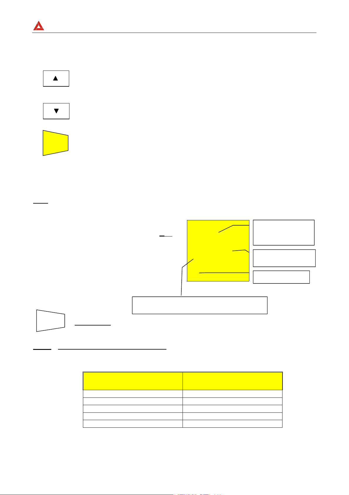
AMPROBE
p
p
4.2.1.2. Modalidad "TIMER"
6. Use las siguientes teclas para seleccionar la duración de la prueba:
Pulse esta tecla para aumentar la duración de la prueba (Tmax=999
segundos).
Pulse esta tecla para disminuir la duración de la prueba (Tmin=10
segundos).
START
7. Pulse la tecla START/STOP .
STOP
El instrumento efectúa la medida acabando en tiempo programado.
999 segundos Valor máximo de la duración de la prueba.
10 segundos Valor mínimo de la duración de la prueba.
MULTITEST1000
Nota: Pulse una segunda vez la tecla START/STOP GO si se quiere detener la prueba en
curso.
)
Al término de la prueba, en el caso en
que el valor de la resistencia R
resulte inferior a R
(que depende de
MAX
ISO
R
ISO
2.07MΩ
Valor de la
resistencia de
aislamiento
R
ISO.
la tensión aplicada ver siguiente Tabla),
y que la prueba sea realizada al valor
de tensión seleccionado, el
instrumento, emite una doble señal
acústica que señala el resultado
500 V 20s
TIMER
Duración de la
rueba
Modalidad Timer
positivo de la prueba y visualiza los
valores obtenidos.
SAVE
GUARDAR: La prueba se memoriza pulsando dos veces la tecla SAVE
Valor de la tensión nominal seleccionada en la
rueba TIMER
(según lo descrito en el párrafo 5.1).
Nota: El valor máximo de resistencia
R
que el instrumento puede medir en la
MAX
modalidad RISO depende de la tensión nominal seleccionada para la prueba. En
particular tendremos:
Tensión Nominal Seleccionada
para la prueba
50VDC
100VDC
250VDC
500VDC
1000VDC
RMAX = VALOR MÁXIMO DE
RESISTENCIA MEDIDA
99.9MΩ
199.9MΩ
499MΩ
999MΩ
1999MΩ
Valores máximos de resistencia que el instrumento mide en modo RISO en función de la tensión
nominal seleccionada.
SP - 19
Page 64

AMPROBE
y
MULTITEST1000
4.2.2. Situaciones anómalas en la que se puede encontrar durante las pruebas
"MAN" & "TIMER"
)
Al término de la prueba, en el caso en
que el valor de la resistencia R
resulte superior a R
(que depende
MAX
ISO
de la tensión aplicada ver anterior Tabla
4), el instrumento, emite una doble
señal acústica que señala el
resultado positivo de la prueba y
visualizará los valores obtenidos.
Máximo valor de resistencia que puede ser medido
(999MΩ es visualizado si la tensión de 500V fue
seleccionada, ver tabla).
>999 MΩ
500 V 20 s
MAN
R
ISO
El símbolo ">"
significa que el
valor de la
resistencia R
ma
or que R
Duración de la
Modalidad
seleccionada MAN
ISO
es
)
En el caso en que haya efectuado la
prueba a una tensión inferior a la
nominal programada, el instrumento,
emite una señal acústica prolongada
y visualizará los valores obtenidos.
ATENCIÓN: la prueba de la resistencia R
sido efectuada a un valor de tensión inferior al
valor de la tensión nominal programada. Situación
que se puede averiguar en caso de bajo
aislamiento o en presencia de tensiones
SAVE
GUARDAR: La prueba se memoriza pulsando dos veces la tecla SAVE
ISO
ha
(según lo descrito en el párrafo 5.1).
)
Si la tensión presente entre los
terminales es mayor de 30V, el
instrumento no efectuará la prueba,
visualizará después de 5 segundos, en
la pantalla como en la prueba R
modalidad seleccionada.
ISO
R
ISO
0.01MΩ
500 V 20 s
MAN
R
ISO
33V
VOL AG
Modalidad
seleccionada MAN
ATENCIÓN: la
prueba no ha sido
efectuada.
Verifique que el
circuito no tenga
presencia de
tensión.
SAVE
ESTE RESULTADO NO SE PUEDE GUARDAR EN MEMORIA.
SP - 20
Page 65

AMPROBE
4.3. : INDICADOR DE SECUENCIA DE FASES
Gire el conmutador en la posición.
MULTITEST1000
Encienda el instrumento.
ATENCIÓN
No desconectar nunca los terminales de los puntos de medida cuando el
instrumento visualiza el mensaje "MEASURING"
SP - 21
Page 66

AMPROBE
MULTITEST1000
4.3.1. Modalidad " "
1. Conecte los tres cables negro, rejo y verde en las correspondientes terminales de entrada
del instrumento T1, T2, T3. Inserte los extremos de los cables libres en los cocodrilos.
L1
L2
L3
N
T2 T3
T1
T4
Conexión del instrumento para la indicación del sentido cíclico de las fases L1= cable
negro, L2= cable azul, L3= cable verde
2. Conecte los cocodrilos a las tres fases del sistema en examen. El instrumento
visualizará una pantalla del tipo: (después de pulsar la tecla START/STOP):
Valor de la tensión entre Fase1 y Fase2.
386 V
Valor de la tensión entre Fase3 y Fase1
388V 388V
Valor de la tensión entre Fase2 y Fase3
START
3. Pulse la tecla START/STOP para iniciar la prueba de la secuencia de fases,
STOP
)
El instrumento al fin de la prueba
visualiza los valores en el caso de
sentido cíclico correcto., el cable
negro es conectado a la fase1=L1, el
cable azul a la fase2=L2 y el cable
verde a la fase3=L3.
)
El instrumento al fin de la prueba
visualiza los valores en el caso de
sentido cíclico incorrecto
una de las siguientes pantalla serán visualizadas:
123
213
Mensaje 123:
significa que el
sentido cíclico es
correcto
Mensaje 213:
significa que el
sentido cíclico es
incorrecto
SAVE
ATENCIÓN
No desconectar nunca los terminales de los puntos de medida cuando el
instrumento visualiza el mensaje "MEASURING"
GUARDAR: La prueba se memoriza pulsando dos veces la tecla SAVE
(según lo descrito en el párrafo 5.1).
SP - 22
Page 67

AMPROBE
A
j
4.3.2. Situaciones anómalas que se puede encontrar durante las pruebas de
Sentido Cíclico de las Fases
MULTITEST1000
)
En el caso en que el instrumento
detecte al menos una de las tensiones
presentes entre dos de las fases en
examen sea inferior a 100V, no
efectuará la prueba y visualizará la
siguiente pantalla:
)
Si la tensión de la entrada T1 es muy
baja, cuando pulse START/STOP el
instrumento visualizará la siguiente
pantalla.
)
Si la tensión de la entrada T2 es muy
baja, cuando pulse START/STOP el
instrumento visualizará la siguiente
pantalla.
L
VOL
A
l1
A
G
Mensaje “Lo
VOL tAG”:
el instrumento
detecta una
tensión
demasiado baja
y no puede
efectuar la
prueba.
Mensaje “Att no
L1”: tensión de
fase 1 es muy
baja
Mensaje “Att no
L2”: tensión de
fase 2 es muy
baja
)
Si la tensión de la entrada T3 es muy
baja, cuando pulse START/STOP el
instrumento visualizará la siguiente
pantalla.
)
Si dos cables de medida son
conectados a un mismo conductor de
fase, cuando pulse START/STOP el
instrumento visualizará la siguiente
pantalla.
l2
A
l3
ph
Mensaje “Att no
L3”: tensión de
fase 3 es muy
baja
Mensaje “PH
double”: Dos
fases están
conectadas
untas.
SAVE
ESTE RESULTADO NO PUEDE SER MEMORIZADO.
SP - 23
Page 68

AMPROBE
)
Si un cable no está conectado a la
instalación o una fase no está presente,
el instrumento visualizará la siguiente
pantalla
Cable negro= L1 no está conectado a una fase de
la instalación. Tensión entre la fase L3 y fase L1
es nula (L3- L1).
Cable negro= L1 no está conectado a una fase de
la instalación. Tensión entre la fase L1 y fase L2
es nula (L1- L2).
)
Si dos o más cables del instrumento no
están conectados, será visualizada la
siguiente pantalla.
0 V
0 V 388
V
0 V
0 V 0 V
MULTITEST1000
Cable negro= L1
no está
conectado a una
fase de la
instalación.
Tensión entre la
fase L2 y fase L3
es nula (L2- L3).
SAVE
GUARDAR: La prueba se memoriza pulsando dos veces la tecla SAVE
(según lo descrito en el párrafo 5.1).
SP - 24
Page 69

AMPROBE
4.4. EARTH ρ: MEDIDA DE LA RESISTENCIA DE TIERRA Y DE LA RESISTIVIDAD
DEL TERRENO
Gire el conmutador en posición EARTH ρ.
MULTITEST1000
FUNC
La resistencia es medida con el método voltiamperimétrico de 4 cables, el valor medido no
dependerá de los cables utilizados. Para este fin no es necesario la calibración de los
cables.
Si los cables no son los suficientemente largos, alárguelos o utilice cables más largos que
los incluidos en dotación.
Encienda el instrumento.
La tecla FUNC permite seleccionar una de las siguientes modalidades (que
se presentan en orden cíclico):
) Modalidad “2P” (el instrumento realiza la medida de la Resistencia entre
2 puntos).
) Modalidad “3P” (el instrumento realiza la medida de la Resistencia
utilizando 2 picas auxiliares).
) Modalidad “ρ“ (el instrumento mide la resistividad del Terreno).
SP - 25
Page 70

AMPROBE
g
MULTITEST1000
4.4.1. Procedimiento de medida para la modalidad de prueba "2P"
1. Seleccione "2P" modalidad de medida de tierra usando la tecla FUNC.
2. Conecte los cables Negro, Rojo, Verde y Azul a los respectivos terminales de entrada del
instrumento T1, T2, T3, T4 (ver posibles conexiones siguientes).
3. Conecte el cable negro y verde a la tierra a comprobar y los cables rojo y azul a una pica
auxiliar.
Conexión para la medida a 2 puntos
START
STOP
)
Cuando esté acabada la prueba el
4. Pulse la tecla START/STOP. El instrumento inicia la prueba.
instrumento visualizará los valores
siguientes.
Valor Promedio calculado de la resistencia de
tierra se
ún el número de pruebas visualizadas.
T2 T3
T4T1
0.96 Ω
2P 0.93 Ω
ATENCIÓN
EARTH
Valor de la
Resistenci
a medida
Modalidad “2P”.
No desconectar nunca los terminales de los puntos de medida cuando el
instrumento visualiza el mensaje "MEASURING"
SAVE
GUARDAR: La prueba se memoriza pulsando dos veces la tecla SAVE
(según lo descrito en el párrafo 5.1).
Nota: Si la tecla START/STOP es pulsada y mantenida, el instrumento realizará más
pruebas consecutivamente.
5. Cuando un nuevo valor es obtenido por el instrumento, emite un corto sonido y calcula
un nuevo valor promedio.
DISP
6. Pulse la tecla DISP mostrará el valor promedio calculado y la modalidad
de promedio.
CLR
7. Pulse la tecla CLR si quiere cancelar el valor medio de la resistencia y el
número de mediciones incluidas en el cálculo.
SP - 26
Page 71

AMPROBE
Cuando las condiciones de trabajo impiden la realización de la modalidad de “3P” como
por ejemplo en el centro de la ciudad. En sistemas TT es posible medir la resistencia de
tierra con el método simplificado “2P” que proporciona un valor superior a la modalidad
“3P”.
Es necesario una pica auxiliar; debe tener una resistencia de tierra no significativa y debe
ser independiente del sistema de tierra en prueba.
En el dibujo anterior se utiliza una tubería de agua como pica auxiliar. Pero cualquier
objeto metálico con conexión a tierra puede ser utilizado.
Ejemplo: Si el usuario realiza tres pruebas consecutivas el instrumento visualiza
1ª medida:
visualización principal = valor de la resistencia medida (Ej: 0.90Ω)
visualización secundaria en el lado izquierdo = 001 (nº. de mediciones = 1
significa que se ha realizado 1 medida de tierra)
visualización secundaria = promedio de mediciones realizadas (en el caso
de haber realizado una sola medición el valor medio es igual al valor
medido, en este caso 0.90Ω)
2ª medición:
visualización principal = valor de la resistencia medida (Ex: 0.96Ω)
visualización secundaria = promedio de mediciones realizadas
((Val1+Val2)/ nº. de mediciones = (0.90+0.96)/2 = 0.93Ω)
3ª medición:
visualización principal = valor de la resistencia medida (Ex: 0.93Ω)
visualización secundaria = promedio de mediciones realizadas
((Val1+Val2)/ nº. de mediciones = (0.90+0.96+0.93)/3 = 0.93Ω)
MULTITEST1000
Nota Cualquier medida con resultado mayor a 1999Ω no se incluye en el cálculo del
valor medio.
Ejemplo: 1ª medición:
visualización principal: 1.07Ω
visualización secundaria: 1.07Ω
2ª medición:
visualización principal: 4.15Ω
visualización secundaria: 2.61Ω
3ª medición: (no incluida en el valor medio)
visualización principal: >1999Ω
visualización secundaria: 2.61Ω
SP - 27
Page 72

AMPROBE
MULTITEST1000
4.4.1.1. Medida de la resistencia de tierra desde una toma de corriente
En instalaciones TT es posible realizar medidas de tierra con el método simplificado que
proporciona un valor por exceso (por lo tanto más seguro), utilizando el NEUTRO de la
compañía eléctrica tomado directamente de la toma de corriente como pica auxiliar; si
está también disponible la conexión de tierra, la medición, naturalmente puede ser
realizada directamente en la toma de corriente entre NEUTRO y TIERRA.
Aunque esta prueba no está contemplada por la CEI 64.8 proporciona un valor que tras
muchas comparaciones con el método 3-wires ha demostrado ser indicativo de la
resistencia de tierra.
T2 T3
T1
T4
Medida de Tierra con el método simplificado en el cuadro eléctrico
ATENCIÓN
Si quiere realizar la medición utilizando el neutro y el tierra de una instalación
estándar, puede accidentalmente conectarlo a la fase. En este caso el
visualizador mostrará la tensión, el símbolo (conexión incorrecta) y no se
realizará aunque pulsemos START/STOP.
ATENCIÓN
No desconectar nunca los terminales de los puntos de medida cuando el
instrumento visualiza el mensaje "MEASURING"
SP - 28
Page 73

AMPROBE
p
MULTITEST1000
4.4.2. Procedimiento de medida para la modalidad de prueba "3P"
Las medidas son realizadas de acuerdo a las normas CEI 64.8, IEC 781, VDE 0413,
EN61557-5.
1. Seleccione la modalidad de medida de tierra "3P" usando la tecla FUNC.
2. Conecte el cable Negro, Rojo, Verde y Azul a los correspondientes terminales de entrada
del instrumento T1, T2, T3, T4
3. Conecte el cable negro y verde a la tierra a comprobar y los cables rojo y azul a una pica
auxiliar.
T2
T4T1
T3
Conexión para la medida a 3 puntos
Realizando mediciones de pequeños sistemas de tierra, la pica de corriente debe ser
posicionada a una distancia de la tierra en pruebas correspondiente a 5 veces la diagonal
del área del sistema de tierra en prueba, realizando mediciones en grandes sistemas la
distancia podría reducirse a una vez la diagonal.
START
STOP
)
Al finalizar la prueba el instrumento
visualizará siguiente valor.
Valor promedio de la resistencia de tierra
calculada
4. Pulse la tecla START/STOP. El instrumento inicia la prueba.
EARTH
0.96 Ω
or el número de pruebas realizada.
2P 0.93 Ω
Valor de la
Resistencia
medida
Modalidad “2P”.
ATENCIÓN
No desconectar nunca los terminales de los puntos de medida cuando el
instrumento visualiza el mensaje "MEASURING"
SAVE
GUARDAR: La prueba se memoriza pulsando dos veces la tecla SAVE
(según lo descrito en el párrafo 5.1).
SP - 29
Page 74

AMPROBE
Nota: Si la tecla START/STOP es pulsada y mantenida, el instrumento realizará más
pruebas consecutivas.
5. Cuando un nuevo valor ha sido adquirido el instrumento emite un corto sonido y
calcula el nuevo valor promedio.
MULTITEST1000
DISP
CLR
Ejemplo: Si el usuario realiza tres pruebas consecutivas el instrumento visualiza
6. Pulse la tecla DISP mostrará el valor promedio calculado y la modalidad
de promedio.
7. Pulse la tecla CLR si quiere cancelar el valor medio de la resistencia y el
número de mediciones incluidas en el cálculo.
1ª medida:
visualización principal = valor de la resistencia medida (Ej: 0.90Ω)
visualización secundaria en el lado izquierdo = 001 (nº. de mediciones = 1
significa que se ha realizado 1 medida de tierra)
visualización secundaria = promedio de mediciones realizadas (en el caso
de haber realizado una sola medición el valor medio es igual al valor
medido, en este caso 0.90Ω)
2ª medición:
visualización principal = valor de la resistencia medida (Ex: 0.96Ω)
visualización secundaria = promedio de mediciones realizadas
((Val1+Val2)/ nº. de mediciones = (0.90+0.96)/2 = 0.93Ω)
3ª medición:
visualización principal = valor de la resistencia medida (Ex: 0.93Ω)
visualización secundaria = promedio de mediciones realizadas
((Val1+Val2)/ nº. de mediciones = (0.90+0.96+0.93)/3 = 0.93Ω)
Nota Cualquier medida con resultado mayor a 1999Ω no se incluye en el cálculo del
valor medio.
Ejemplo: 1ª medición:
visualización principal: 1.07Ω
visualización secundaria: 1.07Ω
2ª medición:
visualización principal: 4.15Ω
visualización secundaria: 2.61Ω
3ª medición: (no incluida en el valor medio)
visualización principal: >1999Ω
visualización secundaria: 2.61Ω
SP - 30
Page 75

AMPROBE
4.4.3. Modalidad "ρ": procedimiento de medida
La resistividad de terreno es una medición muy útil. Su valor puede ayudar a diseñar
correctamente el sistema de Tierras.
Las medidas son realizadas de acuerdo a las normas CEI 64.8, IEC 781, VDE 0413,
EN61557-5
1. Seleccione la modalidad de medida de tierra "ρ" usando la tecla FUNC.
2. Conecte el cable Negro, Rojo, Verde y Azul a los correspondientes terminales de entrada
del instrumento T1, T2, T3, T4.
3. Conecte los cables a las picas auxiliares.
T2 T3 T4T1
MULTITEST1000
a
a
Medida de la resistividad de tierra
U
4. Para seleccionar la distancia DIST entre picas. Este parámetro puede
)
n
DIST
Al finalizar la prueba el instrumento
visualizará la siguiente pantalla.
programarse desde 1 a 10 metros o 3 a 30 pies.
-ρ
a
a
5 m
Distancia de la programación del valor entre picas.
SE LE
5. Pulse las teclas y para seleccionar la distancia.
RCL
ESC
START
7. Pulse la tecla START/STOP. El instrumento inicia la prueba.
STOP
6. Pulse la tecla ESC para abandonar este menú confirmando los cambios.
SP - 31
Page 76

AMPROBE
MULTITEST1000
)
Al finalizar la prueba el instrumento
visualizará la siguiente pantalla.
ρ
36.5 Ωm
Valor de la Resistividad de tierra
2 0.93 Ω
ATENCIÓN
No desconectar nunca los terminales de los puntos de medida cuando el
instrumento visualiza el mensaje "MEASURING"
SAVE
Nota: Si la tecla START/STOP es pulsada y mantenida, el instrumento realizará más
GUARDAR: La prueba se memoriza pulsando dos veces la tecla SAVE
(según lo descrito en el párrafo 5.1).
pruebas consecutivamente.
8. Cuando un nuevo valor es obtenido por el instrumento, emite un corto sonido y calcula
un nuevo valor promedio.
DISP
CLR
Nota: Cada prueba con resultado superior a 1999Ω no es insertado en el cálculo del
Ejemplo: 1ª medición: (D=1):
9. Pulse la tecla DISP mostrará el valor promedio calculado y la modalidad
de promedio.
10. Pulse la tecla CLR si quiere cancelar el valor medio de la resistencia y el
número de mediciones incluidas en el cálculo.
valor medio.
visualización principal: 6,6Ωm
visualización secundaria: 6,6Ωm
2ª medición (D=1):
visualización principal: 4,15Ω
visualización secundaria: 2,61Ω
3ª medición: (no incluida en el valor medio)
visualización principal: >1999Ω
visualización secundaria: 2,61Ω
SP - 32
Page 77

AMPROBE
r
r
4.5. SITUACIONES ANOMALAS MODALIDAD EARTH ρ
)
Si el sistema amperimétrico está
cortado, cuando pulsamos
START/STOP el instrumento no puede
medir la corriente mínima, por tanto
aparecerá una pantalla como la
siguiente. Asegúrese que los
terminales estén conectados
correctamente y que la pica de
corriente (conductor azul) no ha sido
colocada en terreno no conductivo. Si
es necesario, eche agua alrededor de
la pica.
---
- - - c
MULTITEST1000
rC indica un valo
alto de
resistencia.
SAVE
)
Si el instrumento mide una tensión de
interferencia superior a 30V en el
circuito amperimétrico, no realiza la
prueba y aparece la siguiente pantalla.
Tensión en el circuito amperimétrico
SAVE
)
Si la resistencia medida es superior a
la escala del instrumento, después de
pulsar START/STOP el instrumento
realiza la prueba y aparece la siguiente
pantalla.
ESTE RESULTADO NO PUEDE SER MEMORIZADO.
ESTE RESULTADO NO PUEDE SER MEMORIZADO.
31 V
VOL AG
>1999Ω
--- ---
1999Ω es el valo
máximo de
escala medible
del instrumento.
SP - 33
Page 78
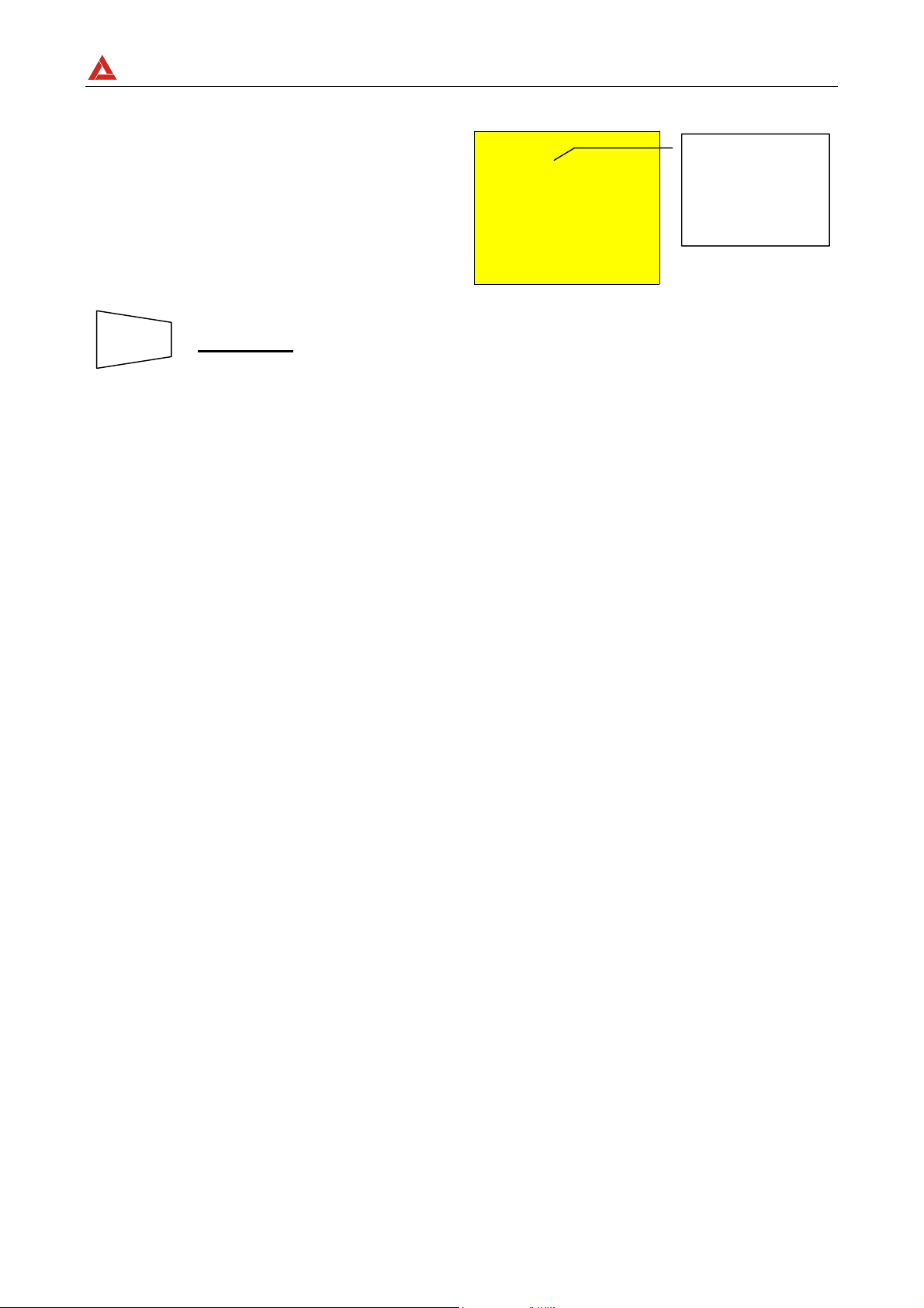
AMPROBE
r
)
Si la medida de la resistividad es mayor
que el siguiente valor 1999x6.28x
(distancia entre picas seleccionada),
después de pulsar START/STOP el
instrumento realiza la prueba y aparece
la siguiente pantalla.
>12.55
3- - - m
k
Ωm
Ω
MULTITEST1000
12.55KΩm es el
margen superio
del instrumento
con distancia=
3m.
SAVE
GUARDAR: La prueba se memoriza pulsando dos veces la tecla SAVE
(según lo descrito en el párrafo 5.1).
SP - 34
Page 79

AMPROBE
MULTITEST1000
5. COMO GUARDAR, RECUPERAR Y BORRAR DATOS GUARDADOS
EN MEMORIA
5.1. TECLA GUARDAR: "SAVE"
Si los resultados relativos a las pruebas realizadas van a ser guardados debe proceder
como se indica a continuación:
SAVE
1. Pulse la tecla SAVE una vez.
)
Si la memoria del instrumento no está
vacía visualiza la siguiente pantalla.
MEM
3
Número de memoria en el cual el resultado de
la medición será guardado.
Valor del parámetro PLA relacionado con la
medición a guardar.
2. Utilice las teclas y para aumentar o disminuir el valor del
parámetro PLA (Posición) relacionada a la medición guardar. Este
parámetro ayuda al usuario a clasificar las pruebas realizadas.
Ejemplo: Si las pruebas se van a llevar a cabo en un edificio, el
usuario puede asociar las mediciones realizadas en una
sala con un valor dado de parámetro de posición PLA. De
esta forma valores diferentes del parámetro PLA
corresponderán a diferentes salas.
PLA 02
SAVE
RCL
ESC
3. Pulse la tecla SAVE de nuevo, el instrumento emite dos pitidos,
confirmando que el resultado ha sido guardado.
Pulse la tecla RCL/ESC en cualquier momento para salir del menú
memoria y volver a la medición seleccionada.
SP - 35
Page 80

AMPROBE
5.2. TECLA RECUPERAR: "RCL"
Si se quieren consultar los resultados relativos a las pruebas efectuadas y memorizadas
proceda del siguiente modo
MULTITEST1000
RCL
ESC
DISP
1. Pulse la tecla RCL/ESC
)
Si la memoria del instrumento no está
vacía se visualizará la siguiente
pantalla.
Número de la posición de memoria en el que
será memorizada la medida.
MEM
3
Pla 02
Valor del parámetro PLA que será asociado
2. Utilice las teclas W y V para seleccionar el número de memória que se
quiere visualizar.
3. Pulse la tecla DISP mostrará el valor promedio calculado y la modalidad
de promedio.
4. Utilice las teclas y para seleccionar el número de localización de
memoria a visualizar.
RCL
ESC
Pulse la tecla RCL/ESC en cualquier momento para salir del menú
memoria y volver a la medición seleccionada.
SP - 36
Page 81

AMPROBE
q
5.3. BORRAR: TECLA “CLR”.
Si se quieren borrar los resultados relativos de algunas pruebas efectuadas y
memorizadas proceda del siguiente modo:
MULTITEST1000
RCL
ESC
1. Pulse la tecla RCL/ESC. El instrumento visualizará la siguiente pantalla:
Número de la posición de memoria en el que
será memorizada la medida.
Valor del parámetro PLA que será asociado
con la medida
2. Use las teclas y para seleccionar la localización del número de
memoria.
ue seráguardada.
MEM
3
Pla 02
ATENCIÓN
El instrumento cancelará todos los resultados guardados desde la
localización de memoria seleccionada hasta la última.
DISP
CLR
RCL
ESC
3. Pulse la tecla DISP mostrará el valor promedio calculado y la modalidad
de promedio.
4. Pulse CLR una vez. Se visualizará el símbolo "clr" parpadeando.
Ahora hay dos posibilidades:
Última localización con datos guardados.
MEM
Cl
El instrumento cancela las memorias desde la
CLR
RCL
ESC
n.2 hasta n.8, donde n.2 es la seleccionada
por el usuario mientras n.8 es la última prueba
guardada en el instrumento.
Pulse CLR de nuevo si se quiere cancelar las pruebas
desde la seleccionada hasta la última guardada.
Pulse RCL/ESC para anular la cancelación. El símbolo "clr"
parpadeando desaparece.
Pulse la tecla RCL/ESC en cualquier momento para salir del menú
memoria y volver a la medición seleccionada.
02 08
SP - 37
Page 82

AMPROBE
MULTITEST1000
6. RESETEADO DEL INSTRUMENTO Y DE LOS PARÁMETROS
ESTÁNDAR
ANTES DE EFECTUAR UN RESETEADO DEL INSTRUMENTO GUARDE TODOS LOS
DATOS RELATIVOS A LAS MEDIDAS EFECTUADAS DESCARGÁNDOLOS EN EL
PC.
6.1. PROCEDIMIENTO DE RESETEADO
1. Pulse las teclas DISP, CLR, RCL y la tecla ON/OFF.
2.
Se visualizará en 5 segundos la
siguiente pantalla, el instrumento
emitirá una señal acústica y
visualiza la pantalla
correspondiente a la función
seleccionada.
es
ATENCIÓN
cuando se ejecute el procedimiento de Reseteado son borrados todos los
datos residentes en memoria.
6.2. PARÁMETROS ESTÁNDAR
Después del RESET los parámetros por defecto programado en el instrumento serán:
Función Parámetro RESET parámetro x defecto
Modalidad AUTO
LOWΩ
R
ISO
EARTH ρ
Memoria
Calibración Offset
Modalidad R+/R- TIMER
Modalidad MAN
Tensión de prueba 500V
Modalidad TIMER TIMER es programado a 60s
Parámetro DIST DIST = 1
Parámetro PLA P = 1
Estado Memoria 0
TIMER es programado a 1s
0
SP - 38
Page 83
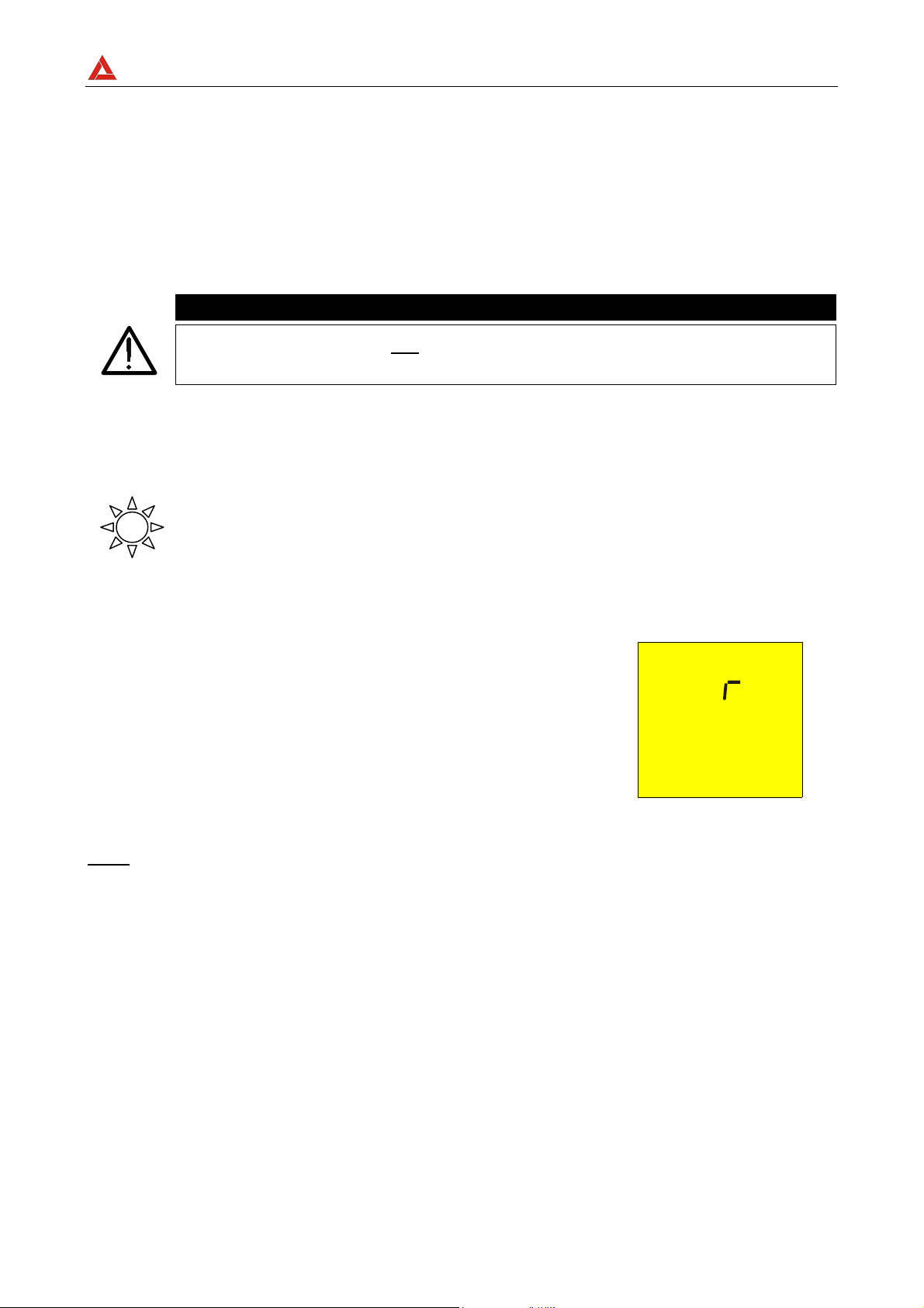
AMPROBE
MULTITEST1000
7. CONEXIÓN DEL INSTRUMENTO A UN PC
La conexión entre un PC y el instrumento se realiza mediante una conexión al puerto serie
mediante el paquete de software.
Antes de efectuar la conexión es necesario que seleccione el puerto COM utilizado para la
transmisión. Para ajustar este parámetro inicie el software y consulte “la ayuda” en línea
del programa
ATENCIÓN
El puerto seleccionado NO debe contener otros dispositivos o aplicaciones
(ej. ratón, módem, etcétera).
Para transmitir los datos memorizados del instrumento al PC siga el siguiente
procedimiento:
1. Gire el Conmutador en posición RS232.
Proceda como indica la ayuda del programa de gestión para la
transmisión de las medidas efectuadas.
)
La comunicación se producirá entre el
instrumento y el PC
SE
Nota: La velocidad de descarga es de: 9600 baud (ver instrucciones del manual del
software).
SP - 39
Page 84

AMPROBE
MULTITEST1000
8. MANTENIMIENTO
8.1. GENERALIDADES
1. El instrumento que Usted ha adquirido es un instrumento de precisión. Durante el uso
y el almacenamiento respete las recomendaciones enumeradas en este manual para
evitar posibles daños o peligros durante el uso.
2. No utilice el instrumento en entornos caracterizados por elevadas tasas de humedad o
temperatura. No lo exponga directamente a la luz del sol.
Apague siempre el instrumento después del uso. Si prevé no utilizarlo por un largo
periodo de tiempo quite las baterías para evitar derrame de líquidos que puedan
perjudicar los circuitos internos del instrumento.
8.2. CAMBIO DE BATERIAS
Cuando el símbolo es visualizado deberá reemplazar las baterías.
ATENCIÓN
Sólo técnicos cualificados pueden efectuar esta operación. Antes de efectuar
esta operación asegúrese de haber desconectado todos los cables de los
terminales de entrada. . El instrumento es capaz de mantener los datos
guardados aunque las baterías no estén instaladas.
1. Apague el instrumento con la tecla ON/OFF.
2. Desconecte los cables de los terminales de entrada.
3. Destornille los tornillos de fijación de la tapa de baterías y saque dicha tapa.
4. Reemplace las baterías con 6 nuevas del mismo tipo
1. Coloque de nuevo la tapa, fíjela con los tornillos.
8.3. LIMPIEZA DEL INSTRUMENTO
Para la limpieza del instrumento utilice un paño suave y seco. Nunca use paños húmedos,
disolventes, agua, etc.
SP - 40
Page 85

AMPROBE
MULTITEST1000
9. ESPECÍFICACIONES TÉCNICAS
9.1. CARACTERÍSTICAS TÉCNICAS
La precisión está indicada como [% de la lectura ± número de cifras]. Está referida a las
siguientes condiciones atmosféricas listadas en el párrafo 9.2.1.
- Continuidad (LOWΩ)
Modalidad de prueba
AUTO, R+TIMER, R-TIMER
Corriente de prueba > 200mA CC para R≤5Ω (incluida la calibración
Resolución medida de la corriente 1mA
Tensión en vacío 6V < V
Rango de Medida (Ω) Resolución (Ω)
0,01 – 19,99 0,01
20,0 – 99,9 0,1
< 12V
0
Precisión
±(2% lec + 2 dgt)
- Resistencia de Aislamiento (R
Tensión de prueba (V)
50
100
250
500
1000
Selección Automática del rango de medida
Tensión de vacío Tensión de Prueba nominal
Corriente de cortocircuito <6,0mA a 500V programado
Corriente de medida nominal >2,2mA a 500V sobre 230kΩ
)
ISO
Rango de Medida (Ω) Resolución (Ω)
0,01 - 19,99 0,01
20,0 - 49,9 0,1
50,0 - 99,9 0,1
0,01 - 19,99 0,01
20,0 - 99,9 0,1
100,0 - 199,9 0,1
0,01 - 19,99 0,01
20,0 - 199,9 0,1
200 - 249 1
250 - 499 1
0,01 - 19,99 0,01
20,0 - 199,9 0,1
200 - 499 1
500 - 999 1
0,01 - 19,99 0,01
20,0 - 199,9 0,1
200 - 999 1
1000 - 1999 1
1mA a 1KΩ x V
(≠ 500 V)
NOM
Precisión
±(2% lec + 2 dgt)
±(5% lec + 2 dgt)
±(2% lec + 2 dgt)
±(5% lec + 2 dgt)
±(2% lec + 2 dgt)
±(5% lec + 2 dgt)
±(2% lec + 2 dgt)
±(5% lec + 2 dgt)
±(2% lec + 2 dgt)
±(5% lec + 2 dgt)
–0% +10%
- Tensión AC
Rango de Medida (V) Resolución (V) Precisión
0 ÷ 460
1
- Medida de la resistencia de Tierra con el método voltiamperimétrico
Rango de Medida (Ω) Resolución (Ω)
0,01 ÷ 19,99
20,0 ÷ 199,9
200 ÷ 1999
Corriente de prueba <10mA 77,5Hz
Tensión en vacío <20V RMS
0,01
0,1
1
SP - 41
±(3% lec + 2 dgt)
Precisión
±(5% lec + 3 dgt)
Page 86

AMPROBE
- Medida de resistividad ρ
Rango de Medida (Ω) Resolución (Ωm)
0.06 ÷ 19,99 Ωm 0,01 Ωm
20.0 ÷ 199.9 Ωm0.1 Ωm
200 ÷ 1999 Ωm1 Ωm
2,00 ÷ 19,99 kΩm 0.01 kΩm
20.0 ÷ 125,5 kΩm (*) 0.1 kΩm
(*) con D = 10m
Corriente de prueba <10mA 77,5Hz
Tensión en vacío <20V RMS
MULTITEST1000
Precisión
±(5% lec + 3 dgt)
9.1.1. Normas de seguridad
El instrumento es conforme a las normas: EN 61010-1 + A2(1997)
Normas de Producción: IEC61557-1, -2, -4, -6
Aislamiento: Clase 2, doble aislamiento
Nivel de Polución: 2
Uso en interiores; altitud max: 2000m
Categoría de sobretensión: CAT III 460V∼ T1-T2-T3-T4 / 265V∼ a tierra
9.1.2. Características generales
Características generales
Dimensiones: 222(L) x 165(La) x 105(H)mm
Peso (baterías incluidas): aprox. 1200g
Alimentación
Tipo baterías: 6 baterías 1.5 V – LR6 – AA – AM3 – MN 1500
Indicación de baterías descargadas: En el visualizador aparece el símbolo
cuando la tensión de las baterías es demasiado
baja
Duración baterías: Cerca de 40 horas en espera (stand-by) o
500 horas en LOWΩ o
250 medidas RISO a 500V/500KΩ o
1000, prueba secuencia de fases
300 Tierra o prueba ρ.
Visualizador: LCD custom 65mmx65mm
Memoria: 350 pruebas
Interfaz: optoaisladas RS232 para descargar datos
archivados al PC.
SP - 42
Page 87

AMPROBE
9.2. AMBIENTE
9.2.1. Condiciones ambientales de uso
Temperatura de referencia: 23° ± 5°C
Temperatura de uso: 0°C ÷ 40 °C
Humedad relativa admitida: <80%
Temperatura de almacenamiento: -10 ÷ 60 °C
Humedad de almacenamiento: <80%
9.2.2. EMC
Este instrumento está proyectado conforme las normas EMC en vigor y la compatibilidad
han sido comprobadas relativamente para EN61326-1 (1998) + A1 (1999).
Este instrumento es conforme a las directivas Europeas estándar para CE.
Este instrumento es conforme a los requisitos de la Directiva europea sobre baja
tensión 72/23/CEE y de la directiva CEM 89/336/CEE, modificado con las 93/68/CEE.
9.3. ACCESORIOS
Los accesorios proporcionados con el instrumento dependen del modelo adquirido de
acuerdo a la siguiente tabla. Se denomina accesorio estándar cuando es vendido
conjuntamente con el instrumento.
MULTITEST1000
Accesorios Estándar
Descripción Código
Conjunto con 4 cables (2m), 4 cocodrilos, 2 puntas de prueba MTL-MT1
Conjunto con 4 cables (banana-cocodrilo) y 4 picas de tierra GP2-CON
Programa de gestión –Software- www.amprobe.com
Cable RS232 - Optico C2001
Bolsa de transporte CC-MT1
Accesorios opcionales
Descripción Código
Conjunto correa de transporte CN0050
SP - 43
Page 88

AMPROBE
MULTITEST1000
10. ASISTENCIA
10.1. CONDICIONES DE GARANTÍA
¡Felicidades! Su nuevo instrumento ha sido fabricado de acuerdo a los estándares de
calidad y contiene componentes de calidad. Ha sido verificado su correcto funcionamiento
en todas sus funciones y comprobado por técnicos cualificados de acuerdo a los
estándares establecidos por nuestra empresa.
Su instrumento tiene una garantía limitada contra materiales defectuoso o de fabricación
de un año desde la fecha de adquisición si en opinión de fabrica el instrumento no ha sido
manipulado.
Si su instrumento se avería debido a materiales defectuosos o de montaje durante
este periodo de un año, se reparará sin cargo o se reemplazará al usuario. Por favor,
tenga a mano su factura con la fecha de compra la cual debe identificar el modelo y
número de serie del instrumento y llame al número abajo indicado:
Departamento de Reparaciones
ATP – Amprobe, TIF, Promax
Miramar, FL
Phone: 954-499-5400
800-327-5060
Fax: 954-499-5454
Website: www.amprobe.com
Por favor obtenga el número RMA antes de devolvernos el producto para su
reparación.
Fuera de U.S.A. el representante local le prestará asistencia. Los límites de garantía
anteriormente indicados cubren solo la reparación y sustitución del instrumento sin
ninguna otra obligación implícita.
SP - 44
Page 89
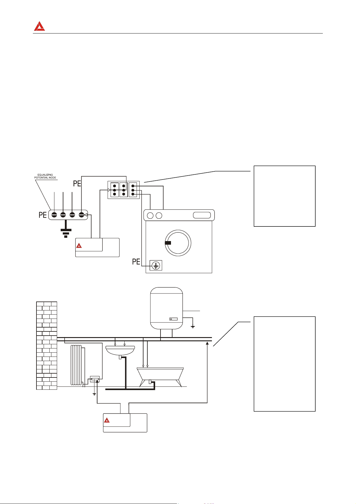
AMPROBE
r
MULTITEST1000
11. FICHAS PRÁCTICAS PARA LAS VERIFICACIONES ELÉCTRICAS
11.1. LOWΩ: MEDIDA DE LA CONTINUIDAD DE LOS CONDUCTORES DE
PROTECCIÓN
OBJETIVO DE LA PRUEBA
Verificar la continuidad de:
a) conductores de protección (PE), conductores equipotenciales principales (EQP),
conductores equipotenciales secundarios (EQS) en los sistemas TT y TN-S.
b) conductores de neutro con funciones de conductores de protección (PEN) en el
sistema TN-C.
NOTA: Esta prueba instrumental va obviamente precedida por un examen visual que
verifique la existencia de los conductores de protección y equipotenciales de color
amarillo-verde y que las secciones utilizadas estén conformes a lo prescrito por
las Normas.
PARTES DE LA INSTALACIÓN A VERIFICAR
Conecte una de las
puntas de prueba
al conductor de
protección de la
toma y el otro al
nodo equipotencial
de la instalación de
tierra.
AMPROBE
Conecte una de las
puntas de prueba a
la masa extraña
(en este caso es el
tubo del agua) y el
otro a la instalación
de tierra el
conductor de
protección
presente po
ejemplo utilizando
en la toma FM más
cercana.
AMPROBE
Ejemplos de medidas de continuidad de los conductores
SP - 45
Page 90

AMPROBE
Verifique la continuidad entre:
a) Polos de tierra de todas las tomas de corriente y colector o nodo de tierra.
b) Bornes de tierra de los aparatos de clase I (calentadores, etc.) y colectores o nodo
de tierra.
c) Masas extrañas principales (tubos de agua, gas, etc.) y colector o nodo de tierra.
d) Masas extrañas suplementarias entre ellas y respecto al borne de tierra.
VALORES ADMISIBLES
Las Normas CEI 64-8/6 no da indicaciones sobre los valores máximos de resistencia que
no deben ser superados para poder declarar positivo el resultado de la prueba de
continuidad.
La CEI 64-8/6 solicita sencillamente al instrumento de medida que indique al operador si
la prueba no ha sido efectuada con una corriente de al menos 0,2 A. y una tensión de
vacío comprendida entre 4 V y 24 V.
Los valores de resistencia se pueden calcular en base a las secciones y a lo largo de los
conductores en examen, en cada modo normalmente si se detectan con el instrumento
valores alrededor de algunos ohmios la prueba se puede considerar superada.
MULTITEST1000
11.2. MEDIDA DE LA RESISTENCIA DE AISLAMIENTO DE LA INSTALACIÓN
ELÉCTRICA (250VCC, 500VCC, 1000VCC)
OBJETIVO DE LA PRUEBA
Verificar que la resistencia de aislamiento de la instalación esté conforme a lo previsto de
las Normas CEI 64-8/6.
NOTA: Esta prueba instrumental debe ser efectuada con el circuito en examen NO
alimentado y con las eventuales cargas desconectadas.
PARTES DE LA INSTALACIÓN A VERIFICAR
a) entre cada conductor activo y el tierra (el conductor de neutro está considerado un
conductor activo excepto en el caso de sistemas de alimentación de tipo TN-C dónde es
considerado parte del tierra (PEN)).
Durante esta medida todos los conductores activos pueden ser conectados entre ellos, en
caso de que el resultado de la medida no entre en los límites normativos hace falta repetir
separadamente la prueba para cada conductor individual.
b) Entre conductores activos.
La norma CEI 64-8/6 recomienda también verificar el aislamiento entre los conductores
activos cuando eso sea posible (ATENCIÓN).
VALORES ADMISIBLES
Los valores de la tensión de medida y de la resistencia mínima de aislamiento puede ser
obtenido de la tabla (CEI64-8/6 Tab. 61A):
SP - 46
Page 91

AMPROBE
MULTITEST1000
Resistencia de
Aislamiento
Tensión nominal del circuito (V)
Tensión de
prueba (V)
(MΩ)
SELV Y PELV * 250
Hasta 500 V comprendidos, excluidos los
circuitos sobre
Más de 500 V
* Los términos SELV y PELV reemplazan en la nueva redacción de la normativa las antiguas definiciones
"Baja tensión de seguridad o funcional."
500
1000
≥0.250
≥0.500
≥1.000
Tabla sinóptica de los valores de las tensiones de prueba y relativos valores límite admitidos para las
tipologías de prueba más común.
SP - 47
Page 92

AMPROBE
MULTITEST1000
11.3. MEDIDA DE LA RESISTENCIA DE AISLAMIENTO DE LOS SUELOS EN
LOCALES DE USO MÉDICO
OBJETIVO DE LA PRUEBA
Verificar que el suelo sea realizado con materiales cuya resistencia de aislamiento esté
conforme a lo previsto de las normas CEI 64-4 (3.05.03).
PARTES DE LA INSTALACIÓN A VERIFICAR
La medida debe ser efectuada entre:
a) Dos electrodos colocados de modo que la distancia entre sus bordes sea de un
metro.
b) Un electrodo puesto sobre el suelo y el nodo equipotencial.
Prueba a):
Conecte una punta de
prueba del instrumento
sobre el nodo
equipotencial y el otro
sobre uno de los dos
electrodos prueba
posicionado sobre el
suelo a una distancia
superior a un metro del
objeto conectado a
tierra.
AMPROBE
Prueba b):
Conecte las puntas de
prueba del instrumento
sobre los electrodos de
prueba posicionando
sobre el suelo a una
distancia reciproca de un
metro entre los bordes.
Medidas de la resistencia de aislamiento de los suelos en locales de uso médico
Los electrodos deben ser constituidos de una plancha teniendo una superficie de apoyo
de 20 cm2, de peso igual a 1 Kg (10N), y de un papel secante húmedo (o paño de algodón
humedecido) de igual superficie entre la plancha metálica y el suelo.
La resistencia de aislamiento es representada, sea para las medidas indicadas en "a" sea
para las medidas indicadas en "b", de la media de 5 o más pruebas efectuadas en
muchas posiciones a distancia superiores a 1 m de objetos unidos a tierra.
VALORES ADMISIBLES
Los valores máximos de la resistencia tan calculada son las siguientes:
- 1 MΩ para medidas efectuadas sobre un suelo nuevo.
- 100 MΩ para las verificaciones periódicas efectuadas sucesivamente al primer año de
la realización del suelo y para la verificación periódica cada cuatro años.
Todos los valores obtenidos deben ser registrados sobre protocolo de las verificaciones
iniciales (64-4 5.1.02).
SP - 48
Page 93

AMPROBE
11.4. VERIFICACIÓN DE LA SEPARACIÓN DE LOS CIRCUITOS
Objetivo de la prueba
La prueba, a efectuar en el caso en que la protección se active a través de separación (
64-8/6 612.4, SELV o PELV o Separación Eléctrica), tiene que verificar que la resistencia
de aislamiento medida sea descrita como a continuación (según el tipo de separación) es
conforme a los límites indicados en la tabla relativa a las medidas de aislamiento.
PARTES DE LA INSTALACIÓN A VERIFICAR
• Sistema SELV (Safety Extra Low Voltage):
9 medir la resistencia entre las partes activas del circuito en prueba (separado) y
las partes activas de los otros circuitos.
9 medir la resistencia entre las partes activas del circuito en prueba (separado) y
tierra.
La resistencia debe resultar no inferior a 0,25MΩ con una tensión de prueba de
500VCC.
• Sistema PELV (Protective Extra Low Voltage):
9 medir la resistencia entre las partes activas del circuito en prueba (separado) y
las partes activas de los otros circuitos.
La resistencia debe resultar non inferior a 0,25MΩ con una tensión de prueba de
250VCC.
MULTITEST1000
• Separación Eléctrica:
9 medir la resistencia entre las partes activas del circuito en prueba (separado) y
las partes activas de los otros circuitos.
9 medir la resistencia entre las partes activas del circuito en prueba (separado) y
tierra.
La resistencia debe resultar no inferior a 0,5MΩ con una tensión de prueba de 500VCC y
1MΩ con tensión de prueba de 1000VCC.
VALORES ADMISIBLES
La prueba tiene resultado positivo cuando la resistencia de aislamiento presenta valores
superiores o iguales a los indicados en la tabla indicada en la sección relativa a las
pruebas de aislamiento.
Observaciones:
• Sistema SELV: es un sistema de categoría cero o sistema a bajísima tensión de
seguridad caracterizado por:
9 Alimentación: fuente autónoma (ej. Baterías, pequeños grupos electrógenos) o de
seguridad (ej. transformadores de seguridad).
9 Separación de protección respecto a otros sistemas eléctricos (doble aislamiento o
reforzado o bien un apantallamiento metálico unido a tierra).
9 No presenta puntos derivados a tierra (aislado por tierra).
• Sistema PELV: es un sistema de categoría cero o sistema a bajísima tensión de
protección caracterizado por:
9 Alimentación: fuente autónoma (ej. Baterías, pequeños grupos electrógenos) o de
seguridad (ej. transformadores de seguridad).
SP - 49
Page 94

AMPROBE
9 Separación de protección respecto a otros sistemas eléctricos (doble aislamiento o
reforzado o bien un apantallamiento metálico unido a tierra).
9 Presenta puntos derivados a tierra (aislado por tierra).
• Separación Eléctrica: es un sistema caracterizado por:
9 Alimentación: transformador separador o fuente autónoma con características
equivalentes (ej. grupo motores generadores).
9 Presenta una separación de protección respecto a otros sistemas eléctricos
(aislamiento no inferior al del transformador separador).
Presenta una separación de protección respecto a tierra (aislamiento no inferior al del
transformador separador).
MULTITEST1000
SP - 50
Page 95

AMPROBE
r
MULTITEST1000
EJEMPLO DE VERIFICACIÓN DE SEPARACIONES ENTRE CIRCUITOS ELÉCTRICOS
Transformador de aislamiento o de
seguridad que efectúa la separación
entre los circuitos.
Between the active
parts of the
separated circuit...
Prueba entre las
partes activas.
...And among those
other circuits
conecte una
punta de prueba
del instrumento
sobre uno de los
dos conductores
del circuito
separado y el
otro sobre uno de
los conductores
de un circuito no
separado.
...Earth
installation
AMPROBE
Medidas de separación entre circuitos en una instalación
Prueba entre las
partes activas y
tierra.
Conecte una
punta de prueba
del instrumento
sobre un de los
dos conductores
del circuito
separado y el
otro sobre el
nudo
equipotencial
Esta prueba sólo
debe se
efectuada para
circuitos SELV o
con separación
eléctrica.
SP - 51
Page 96

AMPROBE
V
V
11.5. MEDIDA DE LA RESISTENCIA DE TIERRA, MÉTODO VOLTIAMPERIMÉTRICO
Técnica para dispersores de tierra de pequeñas dimensiones
Se hace circular una corriente entre el dispersor de tierra en examen y una sonda de
corriente posicionada a una distancia del contorno de la instalación de tierra igual a 5
veces la diagonal del área que delimita la instalación de tierra. Posicione la sonda de
tensión la más cercana a la mitad entre el dispersor de tierra y la sonda de corriente, y
medir la tensión entre los dos.
MULTITEST1000
Rojo
erde
Azul
Negro
Medida de resistencia de tierra de pequeñas dimensiones
Técnica para dispersores de tierra de elevadas dimensiones
Esta técnica está siempre basada en el método voltiamperimétrico pero se utiliza en caso
de que resulte dificultoso posicionar la conexión con tierra auxiliar de corriente a una
distancia igual a 5 veces la diagonal del área de la instalación de tierra. Posicione la
sonda de corriente a una distancia igual a una vez la diagonal de la instalación de tierra.
Para verificar que la sonda de tensión esté situada fuera de las zonas de influencia del
dispersor con tierra en prueba efectuar más medidas partiendo con la sonda de tensión
situada en el punto intermedio entre el dispersor y la sonda de corriente y sucesivamente
desplazando la sonda sea hacia el dispersor de tierra que hacia la sonda de corriente.
Rojo
erde
Negro
Medida de resistencia de tierra de elevada dimensiones
Azul
SP - 52
Utilizar más picas en paralelo y
mojar el terreno circunstante en
caso de que el instrumento no
logre inyectar la corriente
necesaria para efectuar la prueba
a causa de una elevada
resistencia del terreno.
Page 97

AMPROBE
V
MULTITEST1000
11.6. MEDIDA DE LA RESISTIVIDAD DEL TERRENO
OBJETIVO DE LA PRUEBA
Analizar el valor de la resistividad del terreno para definir, en fase de proyecto, la tipología
de los dispersores de tierra a utilizar en la instalación.
EQUIPAMIENTO PARA LA PRUEBA
Para la medida de resistividad no existe valores admisibles, los varios valores obtenidos
utilizando distancias entre las picas “a” crecientes tienen que ser reconducidos en un
gráfico por el que luego, en función de la curva conseguida, se establece el tipo de
dispersor a utilizar. Ya que el resultado de medida puede ser falseado por partes
metálicas enterradas como cañerías, cables, en caso de duda efectuar una segunda
medida con igual distancia "a", pero con el eje de las picas a 90°.
90°
Negro
erde
a
Rojo
Azul
a
a
a
N
e
g
r
aa
R
j
s
o
o
V
A
e
z
r
d
u
l
e
2° Medida:
Las picas se giran 90° con
respecto de la medida
anterior.
El valor de la resistividad es dado de la siguiente relación: ρ=2πaR
donde: ρ= Resistividad especifica del terreno
a= Distancia de las picas (m)
R= Resistencia medida por el instrumento (Ω)
El método de medida permite de obtener la resistividad especifica hasta la profundidad
correspondiente cerca de la distancia “a“ entre dos picas. Usted si aumenta “a “puede ser
obtenido capas de terreno más profundo, por tanto es posible controlar la homogeneidad
del terreno. Por varias medidas de ρ, con “a“ creciente, se puede trazar un perfil como los
siguientes del que es posible establecer el uso de la conexión con tierra más idónea.
SP - 53
Page 98

AMPROBE
)
m
Ω
(
E
ρ
d
n
u
o
r
g
e
h
t
f
o
y
t
i
v
i
t
s
i
s
e
r
c
i
f
i
c
e
p
S
Distance between the rods a(m)
1
2
3
MULTITEST1000
Curva 1: ya que ρ sólo
disminuye en profundidad es
posible sólo utilizar un dispersor
en profundidad.
Curva 2: ya que ρ diminuye sólo
hasta la profundidad A, el
aumento de la profundidad de
los otros dispersores A no
comporta ninguna ventaja.
Curva 3: con el aumento de la
profundidad no se obtiene
ninguna disminución de ρ. Por
tanto el tipo de dispersor a
utilizar es el dispersor de anillo.
VALORACIÓN APROXIMADA DE LOS DISPERSORES (64-12 2.4.1)
En primer lugar la resistencia de una conexión con tierra Rd puede ser calculada con las
siguientes fórmulas (ρ resistividad media del terreno).
a) Resistencia de un dispersor vertical
Rd = ρ / L
L= longitud del elemento de contacto con el terreno
b) Resistencia de un dispersor horizontal
Rd = 2ρ / L
L= longitud del elemento de contacto con el terreno
c) Resistencia de un sistema de elementos enmallados
Como es conocido la resistencia de un sistema complejo con más elementos en
paralelo es cada vez más elevada de la que resultaría de un simple cálculo de
elementos en paralelo. Eso es más verdadero cuanto más cercanos, y por lo tanto
interactivos, resulten los elementos. Por este motivo el uso de la fórmula
subexpuesto en la hipótesis de un sistema enmallado es más rápido y eficaz del
cálculo de los individuales elementos horizontales y verticales:
Rd = ρ / 4r
r = radio del círculo que circunscribe la malla
SP - 54
Page 99

Page 100

Miramar, FL
Phone: 954-499-5400
Fax: 954-499-5454
www.amprobe.com
 Loading...