

Page 1

MAN02
MAN15
MAN30
Manometer
Users Manual
• Mode d’emploi
• Bedienungshandbuch
• Manual d’Uso
• Manual de uso
Page 2

MAN02
MAN15
MAN30
Manometer
Users Manual
MAN02_15_30 Rev001
© 2009 Amprobe Test Tools.
All rights reserved.
English
Page 3

Limited Warranty and Limitation of Liability
Your Amprob e produc t will be free from d efect s in materi al and work manship f or 1 year fro m the
date of purchase. T his warran ty doe s not cover fuses, d ispos able bat teries o r damage fr om accide nt,
neglec t, misuse, alt eration, contamin ation, o r abnorma l conditio ns of ope ration or ha ndling.
Resell ers are no t authoriz ed to exte nd any oth er warrant y on Amprobe’s be half. To obtain s ervic e
during th e warrant y perio d, return t he produ ct with p roof of pur chase to an a uthorize d Amprob e
Test Tools Ser vice Center or to an A mprob e dealer or d istrib utor. See Rep air Sec tion for de tails.
THIS WAR RANT Y IS YOUR ONLY REMEDY. ALL OTHER WA RRAN TIES - WHE THER EX PRESS , IMPLIE D
OR STAUTORY - I NCLUDING IMPLI ED WARRA NTIES O F FITNES S FOR A PARTI CULA R PURPO SE OR
MERCHA NTABILI TY, ARE HERE BY DISCL AIMED. MANUFAC TURER SH ALL NOT BE L IABLE F OR ANY
SPECIA L, IND IRECT, INC IDENTAL O R CONSEQU ENTIA L DAMAGES OR LO SSES, A RISING F ROM ANY
CAUSE O R THEORY. Since s ome sta tes or coun tries do not allow the e xclusion o r limitat ion of an
implied warrant y or of incid ental or co nsequ ential dam ages, t his limit ation of liab ility may n ot apply
to you.
Repair
All test t ools ret urned for w arrant y or non- warrant y repair or f or calibra tion shou ld be acco mpanied
by the foll owing: you r name, com pany’s na me, addr ess, te lephon e number, an d proof of pu rchase.
Additio nally, plea se includ e a brief de script ion of the pr oblem or th e serv ice reque sted an d include
the tes t leads wi th the mete r. Non-war ranty re pair or rep laceme nt charge s should b e remitt ed in the
form of a check, a mon ey order, cre dit card w ith expir ation date , or a purch ase orde r made paya ble
to Ampro be® Test Tools .
In-Warranty Repairs and Repla cement – A ll Count ries
Please r ead the war ranty st atement and chec k your bat tery before req uestin g repair. Duri ng the
warrant y perio d any defec tive test tool ca n be return ed to your A mprobe ® Test Tools dis tributo r
for an exch ange for t he same or li ke produc t. Plea se check t he “Whe re to Buy” se ction o n www.
amprob e.com for a li st of dis tributo rs near you . Additio nally, in the U nited Sta tes and Ca nada In Warrant y repair an d replace ment uni ts can als o be sent to a A mprob e® Test Tools Se rvice C enter (se e
addre ss below).
Non-Warranty Repair s and Repl acement – US and Ca nada
Non- warrant y repair s in the Unite d States a nd Canad a should b e sent to a Am probe® Tes t Tools
Serv ice Cente r. Call Ampro be® Test Tools o r inquire a t your poin t of purcha se for curr ent repai r and
replacement rates.
In USA In Cana da
Amprobe Test Tools Amprobe Test Tools
Everet t, WA 982 03 Mississauga, ON L4Z 1X 9
Tel: 877-AMPROBE (26 7-7623) Tel: 905-890-7600
Non-Warranty Repair s and Repl acement – Europe
Europea n non-wa rranty u nits can b e replac ed by your Am probe ® Test Tools dis tributo r for a nomina l
charge. P lease ch eck the “W here to Bu y” sec tion on ww w.amprobe.co m for a list of d istrib utors ne ar
you.
Europe an Corre spond ence Add ress*
Amprobe
In den Engemat ten 14
79286 Glotter tal, Germany
Tel.: +49 (0) 7684 8009 - 0
*(Corres ponde nce only – no r epair or re placem ent availab le from thi s addres s. Europ ean cust omers
please c ontac t your dis tributo r.)
®
Test Tools Euro pe
3
Page 4
HOLD DIF
DAT A LOGGER
REC
MAX MIN BAT
inH O psi mbar bar mmH2O
2
MANOMETER
1
2
3
4
5
6
7
8
9
1 1
1 0
1 2
1 3
HOLD DIF
DAT A LOGGER
REC
MAX MIN BAT
inH O psi mbar bar mmH2O
2
MANOMETER
1
2
3
4
5
6
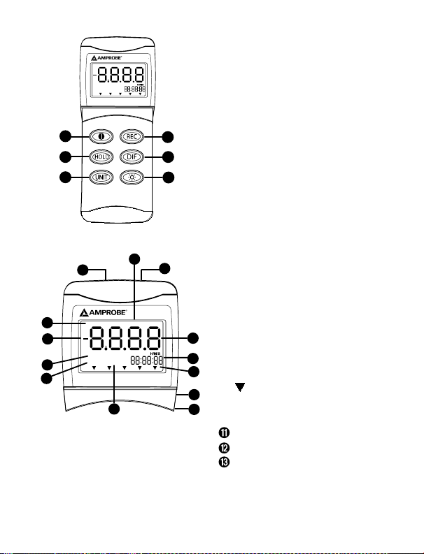
Indicator
➊ ON/OFF Pushbutton
Record pushbutton
➋
Data Hold pushbutton
➌
Differential pushbutton
➍
Unit Selector pushbutton
➎
Backlight pushbutton
➏
Primary data screen displays pressure value
➊
“-” Minus pressure display
➋
MAX MIN pressure recorded
➌
REC starts recording mode and displays
➍
max./min. pressure recorded
➎DC power input jack
USB output port (USB cable not included)
➏
H/M/S 88:88:88 displays time in Hour/
➐
Minute/Second
Pressure unit indication
➑
BAT Low battery indicator
➒
DIF Differential pressure mode
➓
“+” Positive pressure connection input
“-” Negative pressure connection input
Data Hold freezes pressure reading
4
Page 5

MAN02 / MAN15 / MAN30 Manometer
CONTENTS
INTRODUCTION ...................................................................................................................................2
FEATURES .............................................................................................................................................2
STANDARD ACCESSORIES ...................................................................................................................2
QUICK START .......................................................................................................................................3
AUTO POWER OFF ...............................................................................................................................3
OPERATION MODE ..............................................................................................................................3
CALIBRATION MODE ...........................................................................................................................4
Calibration point reference ...........................................................................................................5
MANUAL ZERO SETTING .....................................................................................................................5
TROUBLE SHOOTING ...........................................................................................................................5
Replacing The Battery ...................................................................................................................6
USB PC INTERFACE CAPABILITIES .......................................................................................................6
Download Suite Software installation .........................................................................................6
Operation .......................................................................................................................................6
MAINTENANCE ....................................................................................................................................7
Cleaning .........................................................................................................................................7
SPECIFICATIONS ...................................................................................................................................7
Operating Conditions ....................................................................................................................7
1
Page 6

Congratulations on your purchase of the Amprobe MAN02 MAN15 MAN30 manometers.
These instruments are portable, battery operated pressure measuring device. They are ideal
for HVAC/R technicians measuring pressure level, Medical equipment, Computer peripherals,
pneumatic controls.
INTRODUCTION
The meter will display all LCD segments when it is first turned on for approx. 3 seconds. •
The LCD is divided into two distinct sections : One large (primary) top screen and one smaller •
right bottom screen (relative Clock). The two display areas will constantly update with the
pressure measurements.
FEATURES
The meter measures:
Gauge pressure - • a measurement of pressure that is referred to ambient pressure.
Differential pressure • - a measurement of difference of two pressures .
5 selectable units of measure: in H2o, psi, mbar, bar, mmH2o. (For MAN02)•
11 selectable units of measure: bar, mmHg, ozin2, Kgcm2, psi, inH2O, kpa, ftH2O, inHg, •
cmH2O, mbar (For MAN15 and MAN30)Standard Accessories.
Please check that the tubing is not leaking or damaged before use.•
STANDARD ACCESSORIES
The package contains:
Manometer•
One 9V Battery•
Users manual•
2 connection hoses 4mm(ID) x 6mm(OD) x 500mm•
Carrying Case•
2
Page 7

QUICK START
Unscrew battery compartment on the rear of the instrument and insert the battery. Replace
cover and secure with screw.
Press 1. � to switch the instrument on.
Press 2.
three seconds.
Press 3.
Press 4.
Press 5.
press again to display MIN value of the recording session; and press again to return to real
time recording mode.
The Instrument records only the Max and the Min values for each session. To record all
values for a recording session, use the Download Suite Software.
Press
Note: Clock feature available with gauge pressure only, not differential. The instrument will
automatically switch off after 20 minutes unless sleep mode is disabled.
Press 6. to turn ON the back-light. It automatically switches off after 30 seconds.
AUTO POWER OFF
(Sleep mode function)
This instrument will turn off automatically in approx. 20 minutes after power-on if there are
no key activations. For recording or operating over longer periods of time, you can disable the
sleep mode by pressing � and
An “n” will appear in the middle of the screen at which time you can release the button. (See
Fig. 1) The disable sleep mode will be invalid after power off.
OPERATION MODE
(See Fig. 18.)
Turns instrument on and off.1.
Press momentarily and relative clock starts in the lower right screen.2.
REC is displayed in the middle left of screen (Fig.2).The other functions are locked out except
Power and Backlight.
Press momentarily again and the unit cycles through MAX (Fig. 3) and MIN (Fig.4) and back
to current pressure reading; the record mode is displayed on the LCD.
Press and hold for 3 seconds to turn off the record function and return to normal mode.
Press momentarily to freeze the pressure reading (Fig. 5).3.
Press momentarily, 4. DIF appears on top of the LCD and the display indicates the relative zero
(relative zero causes the value of the display to show as “0.0”) - only the amount of pressure
change will be indicated. Press momentarily again and the unit returns to the normal mode
of pressure differential (see Fig.6).
to select unit of pressure measurement required. For zeroing, press for
for differential pressure measurement.
to freeze the reading on the display. Press again to cancel feature.
to start a recording; press again to display MAX value of the recording session;
and hold for 3 seconds to turn clock feature off.
simultaneously before powering on.
3
Page 8

Differential Pressure: a measurement of the difference between two pressures, i.e. use
differential pressure sensor to measure gauge pressure by leaving one process connection open
to atmosphere and connecting the second sensor port to your system.
Press momentarily and the units will cycle through 5. “InH2o”,”psi”, “mbar”, “ 5.
bar”,“mmH2o” which are indicated on the bottom of the display. (For MAN02)
Press momentarily and the units will cycle through bar, mmHg, ozin2, Kgcm2, psi, inH2O, kpa, 6.
ftH2O, inHg, cmH2O, mbar which are indicated on the bottom of the display (See fig.7 & 8).
(For MAN15 and MAN30)
Press momentarily and the backlight illuminates for approx. 30 seconds, then turns off 7.
automatically.
Press momentarily to decrease the figure when calibration is being performed.
CALIBRATION MODE
Calibration mode is only applicable for a standard manometer calibrator or any qualified meter
calibration facility for annual calibration.
First, manually set the display to zero (no pressure applied to the connector ), refer to the 1.
manual zero procedure.
Turn the meter off.2.
Press 3. � &
to the calibration mode, make sure the units setting on “PSI” to start positive (+) pressure
calibration.
The meter has defaulted as 1.6 psi (for MAN02); 12.00 psi (for MAN15); 24.00 psi (for MAN30) 4.
calibration point, the adjustable pressure range is from 1.5 to 1.7 (for MAN02); 11.70 to
12.30 (for MAN15); 23.40 to 24.60 (for MAN30). If calibration pressure source is not 12.00
psi, increase by pressing
required.
Save the calibration point by pressing 5.
in 2 seconds (See Fig. 10). The meter auto-skips to the negative pressure (-) point for next
calibration mode.
Follow the same procedure as step 4 for the negative pressure calibration point.6.
The LCD now displays” -12.00 “ and small”CA” (See Fig.11 ). Perform the necessary calibration
figure. Refer to your pressure standard if needed.
Again save the calibration point by pressing 7.
and then press
the normal mode (See Fig. 12 ).
If you can’t save by pressing
•Thecalibrationpressuresourcecouldbereferredtothefollowingtable.
•ifyouenteredtherightpositivepressure(+)ornegativepressure(-).
simultaneously, “CA” appears on the display, (See Fig. 9 ) the meter enters
key, or decrease by pressing L key to set calibration point as
key, “SA” and small “CA” appears on the display
;”End”and “CA” appear in another 2 seconds. The meter turns back to
key, i.e. no “SA” appeared, please check the followings:
key, “SA” and “CA” appears in 2 seconds
4
Page 9

If you want to skip positive (+) calibration when in the calibration mode, press key to
skip to negative (-) calibration point.
Calibration point reference
Model Psi Range Calibration point (+/-) Recommended (+/-)
MAN02 0~+/-2 1.6 1.5 t ~ 1.7
MAN15 0~+/-15 12.00 11.70 ~ 12.30
MAN30 0~+/-30 24.00 23.40 ~ 24.60
MANUAL ZERO SETTING
When you set the display to zero( no pressure applied to the connector), press the
for 2 seconds. The meter should display “- 0 .000” from right to left (See Fig.13). Then, the LCD
display shows normal mode.
TROUBLE SHOOTING
Cannot Power on.
Check the battery connections. Replace the battery or attach Optional AC adaptor.
Low BAT indication.
Replace the battery when LCD displays BAT.
No Display.
Make sure the battery is functional.•
check if sleep mode is active. Refer to disable sleep mode on page.6 to turn it off. •
check if the tubing is connected to the meter tightly.•
Err.1.
For the pressure value exceeding the maximum range, “ Err.1” appears on the display (See Fig.
14). Do not exceed rated over pressure range of manometer. Sensor may be damaged.
Err.2.
For the measurement pressure less than minimum range, “Err. 2” will appear (See Fig. 15).
Err.3.
For a differential pressure value larger than maximum display, “Err.3” appears on the display
(See Fig.16 ).
Err.4.
When you set zero, make sure you have disconnected the tubing. If you see an “Err.4” appear
on the display, it means the manometer is damaged (See Fig.17)
Note. Err.4 Will be also appear If the tubing is connected during zero set.
key
5
Page 10

E1OL or E2UL.
When you see these errors while operating computer software, it means pressure source is less
or over than the range of the instrument.
Replace your 9-volt battery when:
The • BAT icon appears on the right of the screen.
The meter will not power on.•
Use of the back-light causes the • BAT icon to appear.
Replacing The Battery
Even if the battery was recently replaced, check its voltage level if you get no response from
your instrument.
To replace the battery:
Remove the tubing from the instrument.1.
Lay the instrument face-down on a clean, flat surface.2.
Remove battery cover.3.
Remove battery from instruments that you do not plan to use for a month or more.
Do not leave battery in instrument.
USB PC INTERFACE CAPABILITIES
The USB cable and the Download Suite software are required to transfer data to a PC. The USB
port is located on the right side of the instrument. The USB Cable is not included. It can be
purchased separately as an optional accessory.
Download Suite Software installation
Insert the Download Suite CD into the CD-ROM drive.
To install the software, follow the on-screen instructions.
Operation
To open the program, double-click the Download Suite icon.
To transfer data to a PC, follow the on-screen instructions.
6
Page 11

MAINTENANCE
The meter is calibrated in house before shipping. When properly maintained, the meter will
maintain its accuracy as specified.
Cleaning
Use a damp cloth and mild soap to clean the case of the MAN15 Manometer, do not use harsh
detergents or abrasives as these may mar the finish or damage the unit’s case with an adverse
chemical reaction.
SPECIFICATIONS
Operating Conditions
Compensated temperature range: 0~50 °C (32~122 °F)•
Operating temperature range: 0~50 °C (32~122 °F)•
Storage temperature range: -20~60 °C (-4~140 °F)•
Operating Humidity Max. 80% RH•
Power Supply : 9 volt battery
Exceeding Maximum pressure will cause permanent sensor damage.
Range: 0 ~ ±2 psi (MAN02)
0 ~ ±15 psi (MAN15)
0 ~ ±30 psi (MAN30)
Power Supply :
Conversion & Resolution
1 psi = Resolution
inch of H₂O
psi 0.0145 0.001
mbar 1 0.1
bar 0.001 0.001
mm of H₂O
0.401 0.01
10.2 1
7
Page 12

1 psi = Resolution
bar 0.068948 0.001
mmHg 51.715073 0.5
ozin2 16.000844 0.2
Kgcm2 0.070309 0.001
psi 1 0.01
inH2O 27.679904 0.3
kpa 6.894757 0.1
ftH2O 2.306659 0.02
inHg 2.036021 0.01
cmH2O 70.306955 1
mbar 68.94757 1
Accuracy: ±0.3% of full scale at ±25°C (77°F)
Repeatability: ±0.2%~0.5% of full scale
Linearity / Hysteresis: ±0.29% to 1% of full scale
Combined accuracy: ±1.0% of full scale
Dimension: 72 x 182 x 30mm
Unit Weight: Approx. 220 (o.485lb) (with battery)
Response Time: 0.5 seconds
Format: Baud rate: 2400 bit/sec
Data bit: 8, Stop bit: 1
Parity: none
8
Page 13

Fig. 1
REC
:
:
H/M/S
DIF
Fig. 2
Fig. 3
Fig. 10
Fig. 4
Fig. 7
Fig. 5
Fig. 8
Fig. 11
Fig. 6
Fig. 9
Fig. 12
9
Page 14

Fig. 13
HOLD DIF
DAT A LOGGER
REC
MAX MIN BAT
inH O psi mbar bar mmH2O
2
MANOMETER
1
2
3
4
5
6
Fig. 14
Fig. 16 Fig. 17
Fig. 15
Fig. 18
10
Page 15

 Loading...