

Page 1
Page 2

Page 3

LT-10
LT-10-EUR
Lamp Tester
Users Manual
7/2013, 6000765 A
©2013 Amprobe Test Tools.
All rights reserved. Printed in China
English
Page 4

Limited Warranty and Limitation of Liability
Your Amprobe product will be free from defects in material and workmanship for one year from
the date of purchase unless local laws require otherwise. This warranty does not cover fuses,
disposable batteries or damage from accident, neglect, misuse, alteration, contamination, or
abnormal conditions of operation or handling. Resellers are not authorized to extend any other
warranty on the behalf of Amprobe. To obtain service during the warranty period, return the
product with proof of purchase to an authorized Amprobe Service Center or to an Amprobe
dealer or distributor. See Repair Section for details. THIS WARRANTY IS YOUR ONLY REMEDY.
ALL OTHER WARRANTIES - WHETHER EXPRESS, IMPLIED OR STATUTORY - INCLUDING IMPLIED
WARRANTIES OF FITNESS FOR A PARTICULAR PURPOSE OR MERCHANTABILITY, ARE HEREBY
DISCLAIMED. MANUFACTURER SHALL NOT BE LIABLE FOR ANY SPECIAL, INDIRECT, INCIDENTAL
OR CONSEQUENTIAL DAMAGES OR LOSSES, ARISING FROM ANY CAUSE OR THEORY. Since
some states or countries do not allow the exclusion or limitation of an implied warranty or of
incidental or consequential damages, this limitation of liability may not apply to you.
Repair
All Amprobe returned for warranty or non-warranty repair or for calibration should be
accompanied by the following: your name, company’s name, address, telephone number, and
proof of purchase. Additionally, please include a brief description of the problem or the service
requested and include the test leads with the meter. Non-warranty repair or replacement
charges should be remitted in the form of a check, a money order, credit card with expiration
date, or a purchase order made payable to Amprobe.
In-warranty Repairs and Replacement – All Countries
Please read the warranty statement and check your battery before requesting repair. During
the warranty period, any defective test tool can be returned to your Amprobe distributor for
an exchange for the same or like product. Please check the “Where to Buy” section on www.
Amprobe.com for a list of distributors near you. Additionally, in the United States and Canada,
in-warranty repair and replacement units can also be sent to an Amprobe Service Center (see
address below).
Non-warranty Repairs and Replacement – United States and Canada
Non-warranty repairs in the United States and Canada should be sent to an Amprobe Service
Center. Call Amprobe or inquire at your point of purchase for current repair and replacement rates.
USA: Canada:
Amprobe Amprobe
Everett, WA 98203 Mississauga, ON L4Z 1X9
Tel: 877-AMPROBE (267-7623) Tel: 905-890-7600
Non-warranty Repairs and Replacement – Europe
European non-warranty units can be replaced by your Amprobe distributor for a nominal
charge. Please check the “Where to Buy” section on www.Amprobe.eu for a list of
distributors near you.
Amprobe Europe*
Beha-Amprobe
In den Engematten 14
79286 Glottertal, Germany
Tel.: +49 (0) 7684 8009 - 0
www.Amprobe.eu
*(Correspondence only – no repair or replacement available from this address. European customers please
contact your distributor.)
Page 5

LT-10 / LT-10-EUR Lamp Tester
CONTENTS
SYMBOL ......................................................................................................... 3
SAFETY INFORMATION ................................................................................. 3
UNPACKING AND INSPECTION ..................................................................... 4
FEATURE .........................................................................................................4
OPERATING THE LAMP TESTER ....................................................................5
Attaching and Removing the Antenna ................................................... 6
Attaching and Removing the Adaptor .................................................... 7
LAMP TEST ................................................................................................ 7
Testing Fluorescent Lamps ....................................................................... 8
Using Sodium Lamp Antenna .................................................................. 9
VolTect™ Non-contact Voltage Detection .............................................. 10
Voltage Detection with Antenna ............................................................ 11
Voltage Detection with Probe ................................................................. 12
Pin Test ...................................................................................................... 13
DETAILED SPECIFICATIONS ........................................................................... 14
MAINTENANCE .............................................................................................. 15
TROUBLESHOOTING ...................................................................................... 16
BATTERY REPLACEMENT ............................................................................... 17
1
Page 6
LT-10 / LT-10-EUR Lamp Tester
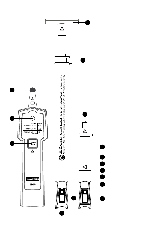
1
2
4
5
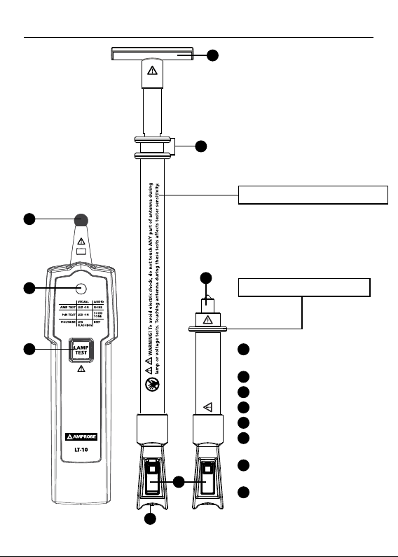
Fluorescent lamp test antenna
8
Sodium Lamp Antenna
3
1
Test probe
(CAT III 300 V, CAT II 600 V)
2
LED indicator
3
For lamp test only!
LAMP TEST button
Do not use with live voltage.
4
Adaptor plate
5
Finger guard
6
Locking switch for
antenna connection
Antenna connection
7
6
to test probe
Sodium lamp antenna
8
7
2
Page 7
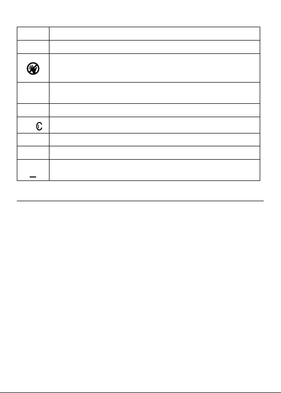
SYMBOLS
Caution! Risk of electric shock.
W
Caution! Refer to the explanation in this manual.
To avoid electric shock, do not touch ANY part of antenna during lamp or voltage tests. Touching antenna during these tests
affects tester sensitivity.
The equipment is protected by double insulation or reinforced
T
insulation.
N
Battery.
Canadian Standards Association (NRTL/C)
)
P
Complies with European Directives.
;
Conforms to relevant Australian standards.
Do not dispose this product as unsorted municipal waste.
=
Contact aqualified recycler.
SAFETY INFORMATION
The meter complies with:
IEC/EN 61010-1 3rd Ed., UL61010-1 2nd Ed. and CAN/CSA C22.2 No. 61010-1-
04 + CSA Update No.1: 2008 to CAT II 300 V, CAT I 600 V, pollution degree 2.
EMC IEC/EN 61326-1
“This product has been tested to the requirements of CAN/CSA-C22.2
No.61010-1, second edition, including Amendment 1, or a later version of
the same standard incorporating the same level of testing requirements.”
Measurement category lll (CAT III) is for equipment intended to form part of
a building wiring installation. Such equipment includes socket receptacles,
fuse panels, and some mains installation control equipment.
Measurement Category II (CAT II) is for measurements performed on
circuits directly connected to low voltage; for example, measurements on
household appliances, portable tools and similar equipment.
CENELEC Directives
The instruments conform to CENELEC low voltage directive 2006/95/EC and
electromagnetic compatibility directive 2004/108/EC
3
Page 8

For Use by Competent Persons
Anyone using this instrument should be knowledgeable and trained about
the risks involved with light fixtures and electrical connections. They
must understand the importance of taking safety precautions and testing
the instrument before and after use to ensure that it is in good working
condition.
W
Warning: Read Before Using
To avoid possible electric shock or personal injury:
• If the tester is used in a manner not specified by the manufacturer,
protection provided by the tester may be impaired.
• For indoor use only. Do not use the tester in rain, snow, damp or wet
locations. Do not use the tester around explosive gas or vapor. Do not
insert or remove the battery in an explosive or flammable environment.
• Comply with local and national safety requirements.
• Use proper protective equipment as required by local or national
authorities.
UNPACKING AND INSPECTION
Your shipping carton should include:
1 LT-10 Lamp Tester
1 Fluorescent lamp antenna
1 Sodium lamp antenna
1 Adaptor plate
1 Carrying case
1 9V alkaline battery
1 Users manual
If any of these items are damaged or missing, return the complete package
to the place of purchase for an exchange.
FEATURES
The Amprobe LT-10 Lamp Tester is a pocket-sized tool designed to
troubleshoot fluorescent lamps prior to installation or removal and verify
presence of voltage of electrical systems.
Three easy steps to troubleshoot lamps:
1. Check if fluorescent (electroluminescent) light bulb is damaged with
LAMP TEST and PIN TEST functions.
4
Page 9

2. Verify if voltage is present at the ballast with VolTect™ non-contact
voltage detection.
3. If light bulb passes the test in step 1 and the voltage is present in step 2,
but the lamp is not working, then replace the ballast.
Features:
• Tests fluorescent (electroluminescent) lights
• Built-in VolTect™ non-contact voltage detection
• Lamp and filament test to check fluorescent and sodium light bulbs
• Simple one-handed, single button operation
• Ultra-compact design for portability
• 48” removable, fully retractable antenna included to test lights and
voltage without a ladder
• Compatible with light bulbs:
- Fluorescent T2, T4, T5, T8, T9, T10, T12 light bulbs
- Fluorescent energy saving light bulbs
- Low pressure sodium vapour bulbs
- High prossure sodium vapour bulbs
- Neon bulbs
- Mercury vapour bulbs
- Halogen metal vapour bulbs
• Insulated antenna sleeve and tip provided to safely extend and
retract during use
• Does not work with LED and incandescent (standard) light bulbs
• Replacement parts: Antenna LT-10-ANT (Item No. 4357839)
OPERATING THE TESTER
The test probe and antennas emit a high frequency voltage (approximately 3
kV) to ionize the light fixtures in order to diagnose a failure.
W Precautions:
• To avoid electric shock, do not touch ANY part of antenna during lamp
or voltage tests. Touching antenna during these tests affects tester
sensitivity.
• When LAMP TEST button is pressed, be alert. Do not touch test probe
or antenna. Discharge can cause electric shock or personal injury.
• Do not attempt to overreach. Make sure you have proper footing and
balance at all times.
5
Page 10
• Do not allow lamp test probe or antenna to touch energized wires.
• To avoid damages to antenna and personal injury, do not attempt to
bend or use the antenna as a crowbar.
• Do not operate the instrument if the case or the battery door is open.
• Do not use if the instrument appears damaged or doesn’t operate
properly. If in doubt, have the instrument serviced.
• The non-contact voltage function is always on. Test on a known live
source within the rated ac voltage range of the product, both before
and after use to ensure the instrument is in good working condition.
Test Functions and Indications:
Test
Lamp test
Pin test
Non-contact voltage detection
Indication
Visual Audio
LED on None
LED on Solid tone
LED flashing Modulated beep
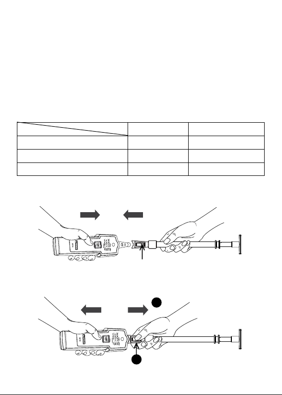
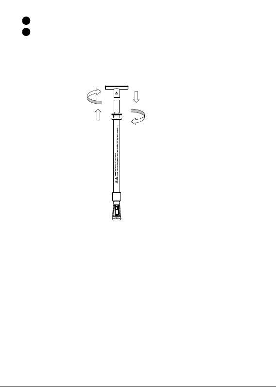
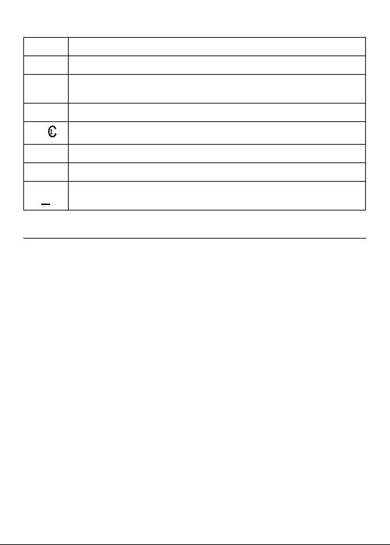
Attaching the Antenna
Make sure the switch is securely locked onto the probe before use.
Figure 1: Attaching the antenna
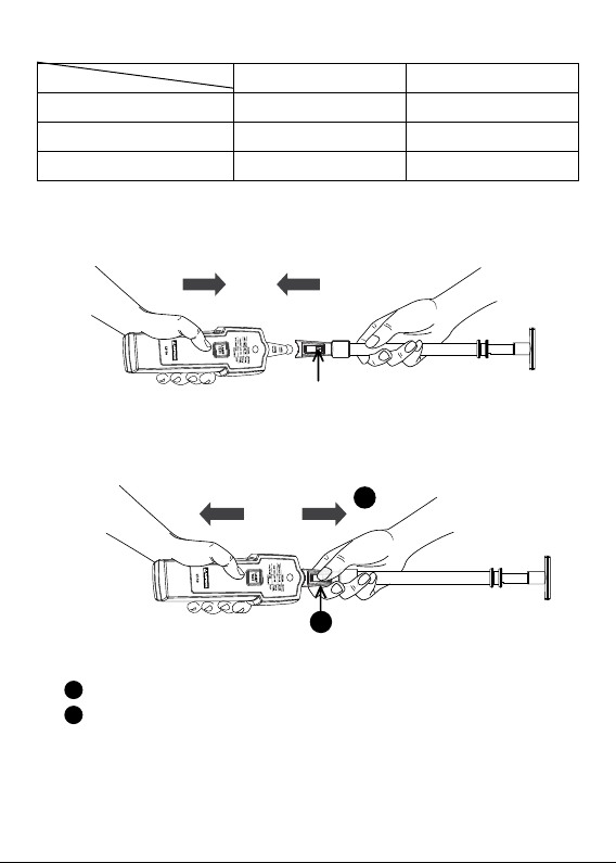
Removing the Antenna
Figure 2: Removing the antenna
Switch
2
1
6
Page 11
1
Press and hold down the switch to unlock.
Remove the antenna from the probe.
2
Removing the antenna in a manner not specified in this manual may cause
damages to the instrument and protection provided by the instrument may
be impaired.
Attaching and Removing the Adapter Plate
Attaching adaptor plate
(clockwise)
Removing adaptor plate
(counterclockwise)
Figure 3: Attaching and
removing the adapter plate
LAMP TEST
Non-contact voltage detection is always on. When the probe or the antenna
is close to energized wires, LED flashes and beeps. Non-contact voltage
detection will be disabled when LAMP TEST button is pressed.
W
Verify lamp test function on a known lamp and/or on the identical
•
lamp model both before and after use to ensure the instrument is in
good working condition.
•
On a very few particular linear fluorescent types, testing against the
glass surface of the lamp may not respond. Testing on the lamp socket
pin via the instrument’s probe (direct metal-to-metal contact) shall
allow good lamp response from a working lamp.
For better results, do the following while testing:
• Press and hold down LAMP TEST button for one second and release it
for one second.
7
Page 12
• Operating time: one second ON, one second OFF for maximum five
cycles and wait for 1 minute before taking another measurement.
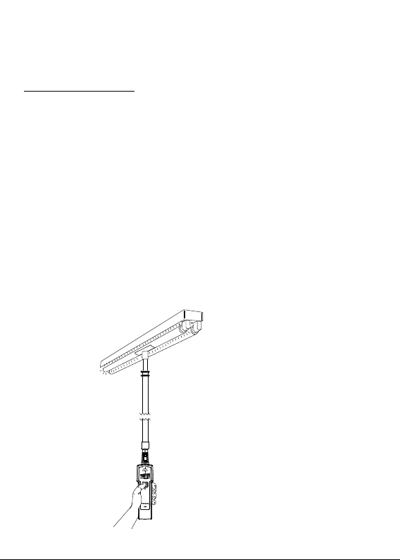
Testing Fluorescent Lamps
Lamp test with antenna
1. Attach the antenna to the test probe and make sure the switch is locked
and secured.
2. Pull the antenna to the desired length up to 48”.
3. Touch the surface of the light bulb with the tip of the antenna.
• To boost the test signal, install the adapter plate.
4. Press and hold down the LAMP TEST button
Do not touch the live parts with the antenna.
• The fluorescent bulb is good if lit during lamp test
• The fluorescent bulb is bad if not lit during lamp test
• If the fluorescent bulb is lit during the lamp test, but does not
function when installed in the light fixture, the spiral wound
filament, the starter or the ballast may be faulty.
To avoid electric shock, do not touch ANY part of antenna
during lamp or voltage tests. Touching antenna during these tests
affects tester sensitivity.
Figure 4: Lamp test against glass
surface in light fixture with the
antenna
8
Page 13
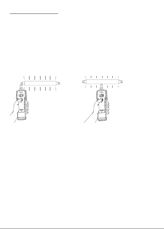
Lamp test with the probe
1. Touch the surface of the light bulb or the lamp socket with the probe.
Do not touch energized parts with the probe.
Do not touch the lamp socket during test. This could lead to faulty
test results and cause electric shock.
2. Press and hold down the LAMP TEST button.
• The fluorescent bulb is good if lit during lamp test
• The fluorescent bulb is bad if not lit during lamp test
• If the fluorescent bulb is lit during the lamp test, but does not
function when installed in the light fixture, the spiral wound
filament, the starter or the ballast may be faulty.
Do not touch the live parts with the probe.
Figure 5: Lamp test
against socket with
the probe
Figure 6: Lamp test
against glass surface
with the probe
Using Sodium Lamp Antenna
Install the sodium lamp test antenna onto the Lamp Tester and make sure
the switch is locked and secured. Verify lamp test function on a known lamp
and/or on the identical lamp model both before and after use to ensure the
instrument is in good working condition.
Note: The level of lamp response/illumination from one lamp type to
another or from one brand to another may vary.
Do not touch the live parts with the lamp test probe. Keep the fingers
behind the hand guard while TEST button is pressed.
Sodium lamp antenna tests:
• Low pressure sodium vapour bulbs
• High prossure sodium vapour bulbs
• Neon bulbs
• Mercury vapour bulbs
• Halogen metal vapour bulbs
9
Page 14

1. Touch the one of the socket pin with the tip of the sodium lamp test
antenna.
2. Press and hold down the LAMP TEST button
• The bulbs is good if glowing.
• If the bulb does not glow, repeat lamp test with touching the other
socket pin.
Note: If the bulb glows with either of socket pins during lamp test, the
lamp is good. In some cases, only part of the bulb will glow, the other part
should glow when testing the other socket pin.
VolTect™ Non-contact Voltage Detection
Amprobe LT-10 Lamp Tester is NOT equipped with a probe tip to be inserted
into the slot of the receptacle contact. Testing voltage that way will not be
reliable.
The LT-10 can only be used for detecting hot wires in outlets when the
wiring is exposed.
With some cables, such as extension cords, hot and neutral wires might be
twisted. In order to reliably test voltage, move the tester along the cable for
some distance (typically a few inches). The tester will only indicate voltage
in places where the hot wire of the twisted wires is closer to the tester. It
will NOT indicate voltage in other places of the cable.
W
WARNING!
• To avoid electric shock, do not touch ANY part of antenna during lamp
or voltage tests. Touching antenna during these tests affects tester
sensitivity.
• If the instrument is used in a manner not specified by the manufacturer,
protection provided by the tester may be impaired.
• Test on a known energized source within the rated ac voltage range of
the instrument both before and after use to ensure the instrument is in
good working condition.
• The non-contact voltage detection function is always on. When the
probe or antenna is close to energized wires, LED flashes and beeps.
Non-contact voltage detection will be disabled when the LAMP TEST
button is pressed.
10
Page 15

• When using the instrument, if LED indicator does not glow or
the instrument does not beep, voltage could still be present. The
instrument indicates active voltage in the presence of electrostatic
fields of sufficient strength generated from the source voltage. If the
field strength is low, the instrument may not provide indication of live
voltage. Lack of an indication occurs if the instrument is unable to sense
the presence of voltage which may be influenced by several factors
including, but not limited to:
- Shielded wire/cables
- Thickness and type of insulation
- Distance from the voltage source
- Fully-isolated users that prevent an effective ground
- Receptacles in recessed sockets or differences in socket design
- Condition of the instrument and batteries
• Do not use if the instrument appears damaged or if it doesn’t operate
properly. Closely examine the tip of the probe for cracks or breakage
before use. If in doubt, have the instrument serviced.
• Do not use the instrument to test voltage higher than the rated voltage
as marked on the instrument.
• Use caution with voltages above 30 V ac as a shock hazard may exist.
• Comply with local and national safety requirements.
• Use proper protective equipment as required by local or national
authorities.
The non-contact voltage (NCV) test can be used to check whether the
ballast is functional by verifying the presence of ac voltages at the input
and output of the ballast, or the energized parts of the light fixture. The
light fixture must be turned on before verifying the presence of ac voltage
with the instrument.
Voltage Detection with Antenna
Do not touch the energized bare parts with the antenna. Test on
energized insulated parts or insulated wires only.
1. Turn the light fixture’s power on.
2. Use the antenna to quickly check the presence of ac voltage to the light
fixture.
• If the LED flashes red and beeps (modulated), there is ac voltage
present.
11
Page 16
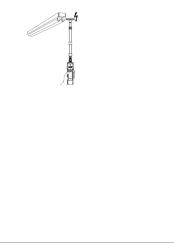
Figure 7: Voltage detection
with antenna
Voltage Detection with Probe
Do not touch the energized bare parts with the probe. Test on
energized insulated parts or insulated wires only.
To avoid electric shock, do not touch ANY part of antenna during lamp
or voltage tests. Touching antenna during these tests affects tester
sensitivity.
1. Turn the light fixture’s power on.
2. Use the probe to detect the presence of ac voltage on the wires at
input of the ballast.
• If the tester’s LED flashes red and beeps, there is ac voltage present.
3. Use the probe to detect the presence of ac voltage on the wires at
output of the ballast.
• If the tester’s LED flashes red and beeps, there is ac voltage present.
The lamp may be faulty.
• If LED and beeper do not activate during voltage detection at the
ballast output wires, the ballast may be faulty.
12
Page 17
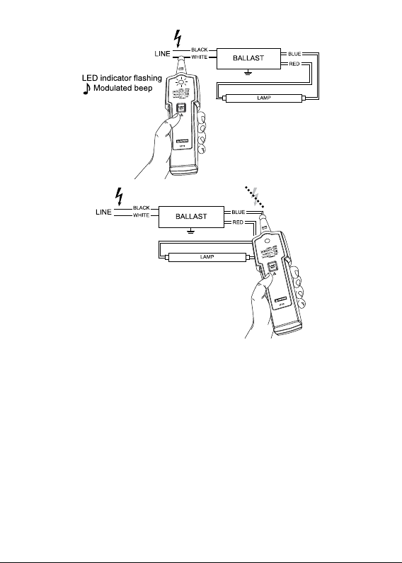
Figure 8: Voltage detection
at ballast input wires
Figure 9: Voltage detection at ballast
output wires
Pin Test
The pin test (filament test) can be used on dual pin fluorescent lamps that
have a filament under the metal cap. The filament is used to excite the gas
inside the tube and turn it on. The lamp will not function correctly if the
filament is broken.
Turn the power off to the light fixture before removing the lamp from
the fixture.
1. Pin test is always on. Plug the lamp pins into the pin test slots on the
back of the tester.
• If the tester does not beep and LED indicator is not on, the filament
is broken. Replace the lamp.
• If the tester beeps and LED indicator is on, the filament is functional.
The pins are good.
13
Page 18
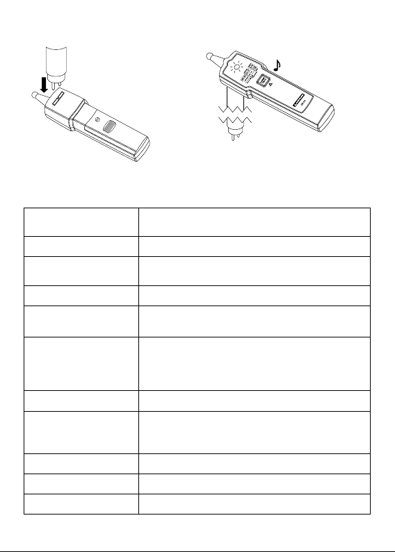
2. Repeat step 1 with the other end of the lamp.
Figure 10: Plug
the lamp into the
pin test slots
Figure 11: Pin test indications
DETAILED SPECIFICATIONS
Test voltage
(with new battery)
Field strength
Maximum antenna
length
Filament test
Non-contact voltage
detection
Non-contact voltage
sensitivity (with probe)
Drop proof
Operating time
Operating temperature
Storage temperature
Operating altitude
Approximately 3 kV / 280 kHz
Approximately 100 μV/m at 260 - 300 kHz
121.92cm (48”)
T2, T4, T5, T8, T9, T10, T12
AC 90 V to AC 600 V, 50/60 Hz
CAT III 300 V, CAT II 600 V
LED illuminates and beeps at approximately 3 mm
(0.12 in) distance from a wire carrying 120 Vac
LED illuminates and beeps at approximately 5 mm
(0.2 in) distance from a wire carrying 230 Vac
1 meter
One second ON, one second OFF for maximum
five cycles and wait for 1 minute before making
another measurement
O
-10
C to +50OC (14OF to 122OF) ≤85% RH
O
-10
C to +50OC (14OF to 122OF) ≤85% RH
Up to 2000 meters
LED indicator ON
Solid continuous beep
14
Page 19

Battery
Battery life
Dimensions
(L x W x H)
Weight
Safety compliance
EMC compliance
Certification
1 x 9V lithium or alkaline battery only,
6LR61/6LF22/MN1604 or equivalent
500 tests (alkaline typically)
Approximately 170 x 40 x 24 mm
(6.69 x 1.57 x 0.94 in)
Approximately 80 g (0.18 lb) with battery
installed
IEC 61010-1, UL 61010-1
CAN/CSA-C22.2 No. 61010-1-2004
IEC 61326-1
CSA and CE
MAINTENANCE AND REPAIR
If the instrument fails to operate, check the battery and replace as
necessary.
Do the following:
1. Replace the battery if the tester does not work.
2. If antenna is not working, check the antenna connection. Make sure the
antenna is locked and secured.
3. Review the users manual to better understand how the tester operates.
Except for the replacement of the battery, repair of the tester should
be performed only by an authorized service center or by other qualified
instrument service personnel.
The front panel and carrying case can be cleaned with a mild solution of
detergent and water. Apply sparingly with a soft cloth and allow to dry
completely before using. Do not use aromatic hydrocarbons, gasoline or
chlorinated solvents for cleaning.
15
Page 20

TROUBLESHOOTING
Lamp tester doesn’t work:
Problem: Possible low or dead battery
Action: Check and/or replace battery
Low lamp tester response:
Problem:
1. Possible low battery
2. Bad contact between the probe/antenna and the lamp tester
Action:
1. Check and/or replace battery
2. Test the area on the lamp where the probe/antenna can make good
contact against lamp glass surface or the lamp socket
Antenna doesn’t work:
Problem:
1. Possible low battery
2. Bad contact between the antenna and the lamp under test
3. Bad connection contact between the probe and antenna
Action:
1. Check and/or replace battery
2. Test the area on the lamp where the antenna can make good contact
against lamp glass surface or the lamp socket
3. Check and re-install the antenna. Make sure the antenna is securely
locked onto the probe. If the antenna is still not working, the
antenna may be damaged. Contact a service center for repair or
antenna replacement
Sodium lamp antenna doesn’t work:
Problem:
1. Possible low battery
2. Bad contact between the probe and the lamp socket
NOTE: The insulated probe may not work on socket of energy saving
lamp.
Action:
1. Check and/or replace battery
2. Test the glass tube on the lamp with the probe.
16
Page 21
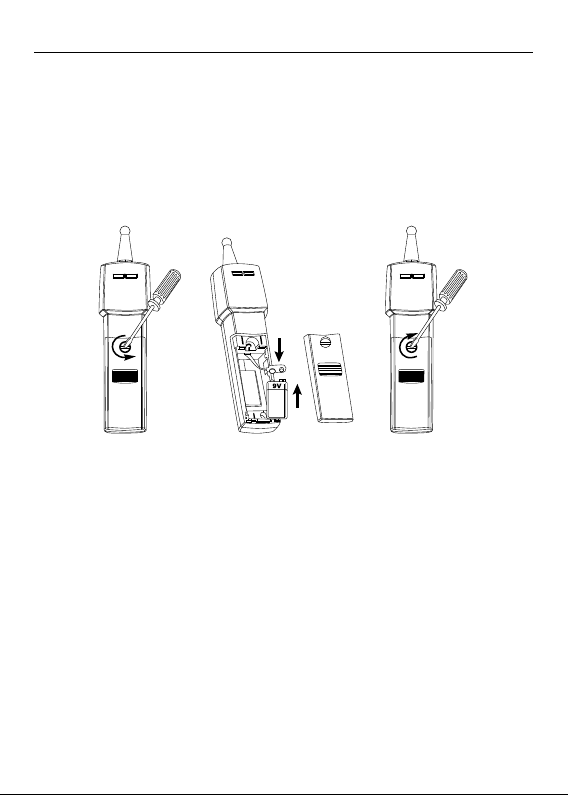
BATTERY REPLACEMENT
Replacing BATTERY follow below steps:
1. On the battery case, turn the screw to “open” position by using a flat
screw driver. Then open the battery cover.
2. Remove battery and replace it with one 9V alkaline or lithium battery
only (6LF22, 6LR61, MN1604 or equivalent). Pay attention to the
polarity signs.
3. Put the battery cover back on and refasten the screw.
1. 2. 3.
Figure 12: Replacing battery
17
Page 22

Page 23

LT-10
LT-10-EUR
Testeur de lampes
Guide d'utilisation
4/2013, 4265801 B
© 2013 Amprobe Test Tools.
Tous droits réservés. Imprimé en Chine
Français
Page 24

Garantie limitée et limitation de responsabilité
Votre produit Amprobe sera exempt de défauts de matériaux et de fabrication pendant un an
à compter de la date d'achat, sauf exigence contraire en vertu de la juridiction locale. Cette
garantie ne s'applique pas aux fusibles, aux piles jetables ou endommagées par accident, à
la négligence, à la mauvaise utilisation, à l'altération, à la contamination ou aux conditions
anormales d'utilisation ou de manipulation. Les revendeurs ne sont pas autorisés à prolonger
toute autre garantie au nom de Amprobe. Pour une réparation au cours de la période de
garantie, retournez le produit avec la preuve d'achat à un centre de service autorisé par
Amprobe ou à un revendeur ou un distributeur Amprobe. Voir la section Réparation pour plus de
détails. CETTE GARANTIE EST VOTRE SEUL RECOURS. TOUTES LES AUTRES GARANTIES – QU'ELLES
SOIENT EXPLICITES, IMPLICITES OU JURIDIQUES – Y COMPRIS LES GARANTIES IMPLICITES
D'ADAPTATION À UN USAGE PARTICULIER OU MARCHAND, SONT EXCLUES. LE FABRICANT NE
SERA PAS RESPONSABLE DES DOMMAGES SPÉCIAUX, INDIRECTS, ACCESSOIRES OU CONSECUTIFS
PROVENANT DE TOUTE CAUSE OU THÉORIE. Etant donné que certains pays ou états n'autorisent
pas l'exclusion ou la limitation des garanties implicites ou des dommages directs ou indirects,
cette limitation de responsabilité peut ne pas s'appliquer à vous.
Réparation
Tout produit Amprobe retourné pour réparation sous garantie ou hors garantie ou pour
l'étalonnage doit être accompagné des documents suivants : votre nom, nom de société,
adresse, numéro de téléphone, et preuve d'achat. De plus, veuillez inclure une brève
description du problème ou du service demandé et incluez les cordons de vérification avec le
compteur. Les frais de réparation ou de remplacement non garantis doivent être réglés sous
forme de chèque, mandat, carte de crédit avec date d'expiration ou bon de commande payable
à Amprobe.
Réparation et remplacement couverts par la garantie – Tous les pays
Veuillez lire la déclaration de garantie et vérifier la pile avant de demander une réparation. Pendant
la période de garantie, tout outil de vérification défectueux peut être retourné à votre distributeur
Amprobe pour un échange de produit identique ou similaire. Veuillez consulter la section « Où
acheter » au www.Amprobe.com pour obtenir une liste des distributeurs près de chez vous. En
outre, aux États-Unis et au Canada, les réparation sous garantie et les unités de remplacement
peuvent également être envoyés à un centre de service Amprobe (voir adresse ci-dessous).
Réparation et remplacement non couverts par la garantie – États-Unis et Canada
Les réparation non couverts par la garantie aux États-Unis et au Canada doivent être envoyés à un
centre de service Amprobe. Appelez Amprobe ou renseignez-vous auprès de votre point de vente
pour les tarifs de réparation et de remplacement actuels.
États-Unis : Canada :
Amprobe Amprobe
Everett, WA 98203 Mississauga (Ontario) L4Z 1X9
Tél. : 877-AMPROBE (267-7623) Tél. : 905-890-7600
Réparation et remplacement non couverts par la garantie – Europe
Les unités hors garantie européennes peuvent être remplacées par votre distributeur
Amprobe pour une somme modique. Veuillez consulter la section « Où acheter » au www.
Amprobe.eu pour obtenir une liste des distributeurs près de chez vous.
Amprobe Europe*
Beha-Amprobe
In den Engematten 14
79286 Glottertal, Allemagne
Tél. : +49 (0) 7684 8009 - 0
www.Amprobe.eu
*
(Correspondance uniquement : aucune réparation ou remplacement à cette adresse. Clients européens,
veuillez contacter votre distributeur.)
Page 25

Testeur de lampes LT-10 / LT-10-EUR
TABLE DES MATIÈRES
SYMBOLE ....................................................................................................... 3
CONSIGNES DE SÉCURITÉ ............................................................................. 3
DÉBALLAGE ET INSPECTION ......................................................................... 4
CARACTÉRISTIQUES ...................................................................................... 4
UTILISATION DU TESTEUR DE LAMPES ........................................................ 5
Montage et démontage de l'antenne ..................................................... 6
Montage et démontage de l'adaptateur ................................................ 6
Testeur de lampes ..................................................................................... 7
Détection de tension sans contact VolTect™ .......................................... 9
Test de broche ...........................................................................................12
CARACTÉRISTIQUES DÉTAILLÉES ..................................................................12
ENTRETIEN ..................................................................................................... 13
DÉPANNAGE .................................................................................................. 14
REMPLACEMENT DE LA PILE ......................................................................... 15
Page 26
Testeur de lampes LT-10 / LT-10-EUR
4
5
1
6
8
1
2
For lamp test only!
Do not use with live voltage.
3
4
5
6
7
Sonde de vérification
(CAT III 300 V, CAT II 600 V)
Indicateur DEL
Bouton LAMP TEST
Plaque adaptatrice
Protège-doigts
Interrupteur de
verrouillage pour le
raccordement d'antenne
Raccordement d'antenne
à la sonde de vérification
2
3
7
Page 27
SYMBOLES
Attention! Risque de choc électrique.
W
Attention! Reportez-vous aux explications de ce guide.
Cet équipement est protégé par une isolation double ou
T
renforcée.
N
Pile.
)
Association canadienne de normalisation (NRTL/C)
P
Conforme aux directives européennes.
;
Conforme aux normes australiennes.
Ne jetez pas ce produit avec les déchets municipaux non triés.
=
Contactez un recycleur qualifié.
CONSIGNES DE SÉCURITÉ
L'appareil de mesure est conforme à :
IEC/EN 61010-1 3e Ed., UL61010-1 2e Ed. et CAN/CSA C22.2 No. 61010-1-04 +
CSA mise à jour No.1 : 2008 à CAT II 300 V, CAT I 600 V, degré de pollution 2.
EMC IEC/EN 61326-1
« Ce produit a été testé conformément aux exigences de la norme CAN/
CSA-C22.2 No.61010-1, deuxième édition, y compris l'amendement 1, ou
une version ultérieure de la norme en incorporant le même niveau de
prescriptions d'essai. »
La catégorie de mesure II (CAT II) correspond aux mesures réalisées sur les
circuits directement raccordés en basse tension; par exemple, des mesures
sur des appareils ménagers, des outils portatifs et appareils similaires.
La catégorie de mesure I (CAT I) est réservée aux mesures exécutées sur les
circuits qui ne sont pas connectés directement au secteur.
Directives CENELEC
Les instruments sont conformes à la directive basse tension CENELEC
2006/95/CE et la directive de compatibilité électromagnétique 2004/108/CE.
Pour utilisation par des personnes compétentes
Toute personne qui utilise cet instrument devrait être bien informée
et formée sur les risques encourus avec les luminaires et les connexions
électriques. Elles doivent comprendre l'importance de prendre les
précautions de sécurité et de tester l'instrument avant et après chaque
utilisation pour s'assurer qu'il est en bon état de fonctionnement.
3
Page 28

W
Avertissement : Lire avant utilisation
Pour éviter tout risque d'électrocution ou de blessure :
• Si le testeur est utilisé d'une manière non spécifiée par le fabricant, la
protection fournie par le testeur peut être altérée.
• Pour usage intérieur seulement. Ne pas utiliser le testeur sous la pluie,
la neige, et dans les endroits humides ou mouillés. Ne pas utiliser le
testeur proximité de gaz explosifs ou de vapeur. Ne pas insérer ou
retirer la pile dans un environnement explosif ou inflammable.
• Conformez-vous aux exigences de sécurité locales et nationales.
• Utilisez un équipement de protection tel que requis par les autorités
locales ou nationales.
DÉBALLAGE ET INSPECTION
Votre emballage doit contenir :
1 testeur de lampes LT-10
1 antenne amovible
1 plaque adaptatrice
1 mallette de transport
1 pile alcaline 9V
1 guide d'utilisation
Si l'un de ces éléments est manquant ou endommagé, retourner l'emballage
complet à votre point d'achat pour un échange.
CARACTÉRISTIQUES
Le testeur de lampes Amprobe LT-10 est un outil de poche conçu pour
dépanner les lampes fluorescentes et de vérifier la présence de tension dans
les installations électriques.
Trois étapes simples pour dépanner des lampes :
1. Vérifiez si l'ampoule fluorescente (électroluminescente) est
endommagée à l'aide des fonctions de test des lampes et des broches
2. Vérifiez si la tension est présente au niveau du ballast à l'aide de la
fonction de détection de tension sans contact VolTech
3. Si ampoule passe le test de l'étape 1 et la tension est présente à l'étape
2, mais la lampe ne fonctionne pas, remplacez le ballast
• Teste les ampoules fluorescentes (électroluminescentes)
™.
4
Page 29

• Détection de tension sans contact VolTech™ intégré
• Teste la lampe et le filament pour vérifier les ampoules fluorescentes
• Utilisation simple d'une seule main, un seul bouton
• Conception ultra-compacte pour la portabilité
• 48’’ amovibles, antenne entièrement rétractable inclus pour tester les
lampes et la tension sans échelle
• Compatible avec toutes les ampoules fluorescentes
(électroluminescentes) :
- T2, T4, T5, T8, T9, T10, T12
- Ampoules à économie d'énergie fluorescentes
• Manchon d'antenne isolé et conseils fournis pour déployer et rétracter
en toute sécurité lors de l'utilisation
• Ne fonctionne pas avec les DEL et les ampoules à incandescence (standard)
• Pièces de rechange : Antenne LT-10-ANT (No. 4357839)
UTILISATION DU TESTEUR
La sonde d'essai / l'antenne émet une tension à haute fréquence (environ 3
kV) pour ioniser les luminaires afin de diagnostiquer la panne.
W Précautions:
• Lorsque le bouton LAMP TEST est pressée, soyez vigilant. Ne touchez
pas la sonde de test ou l'antenne. La décharge peut provoquer un choc
électrique ou des blessures corporelles.
• N'essayez pas d'aller trop loin. Assurez-vous d'avoir un bon équilibre en
tout temps.
• Ne laissez pas la sonde de test ou l'antenne à toucher des fils sous
tension.
• Pour éviter des dommages à l'antenne et des blessures corporelles, ne
pas essayer de plier ou d'utiliser l'antenne comme un pied de biche.
• Ne pas faire fonctionner l'appareil avec le boîtier ou le couvercle de la
pile ouvert.
• Ne pas utiliser si l'instrument semble endommagé ou ne fonctionne pas
correctement. En cas de doute, faites réparer l'instrument.
• La fonction de tension sans contact est toujours activée. Faites un essai
sur une source connue dans la plage nominale de tension alternative
du produit, à la fois avant et après utilisation pour s'assurer que
l'instrument est en bon état de fonctionnement.
5
Page 30
Fonctions de test et indications :
Test
Test de lampes DEL allumée Aucun
Test de broche DEL allumée Tonalité continue
Tension sans contact LED clignote Modulation sonore
Installation de l'antenne
Assurez-vous que l'interrupteur est bien verrouillé sur la sonde avant
utilisation.
Indication
Visuel Audio
Retrait de l'antenne
Interrupteur
Figure 1 : Installation de l'antenne
2
Figure 2 : Retrait de l'antenne
1
Appuyez le bouton et maintenez-le enfoncé pour déverrouiller.
2
Retirez l'antenne de la sonde.
Le retrait de l'antenne d'une manière non spécifiée dans ce guide
pourrait causer des dommages à l'instrument, et la protection fournie par
l'instrument peut être altrérée.
1
6
Page 31

Montage et démontage de l'adaptateur
Montage de la plaque
adaptatrice
Démontage de la plaque
adaptatrice
Figure 3 : Montage et
démontage de l'adaptateur
Testeur de lampes
La détection de tension sans contact est toujours activée. Lorsque la sonde
de l'antenne est proche de fils sous tension, la DEL clignote et émet un
signal sonore. La détection de tension sans contact sera désactivé lorsque le
bouton LAMP TEST est enfoncé.
Pour un meilleur résultat, procédez comme suit lors des tests :
• Appuyez et maintenez enfoncé le bouton LAMP TEST pendant une
seconde et relâchez-le pendant une seconde.
• Cycle de fonctionnement : une seconde ALLUMÉ, une seconde ÉTEINT
pour un maximum de cinq cycles, puis délai d’attente de 1 minute avant
prise d’une nouvelle mesure.
Test de lampe avec la l’antenne
1. Fixez l'antenne à la l’antenne de test et assurez-vous que l'interrupteur
est fermé et verrouillé.
2. Déployez l'antenne à la longueur désirée ou complètement.
3. Touchez la surface de l'ampoule avec la pointe de l'antenne.
• Pour amplifier le signal de test, installez la plaque adaptatrice.
4. Appuyez le bouton LAMP TEST et maintenez-le enfoncé.
Ne pas toucher les parties sous tension avec l'antenne.
• La lampe fluorescente est en bon état si elle s'allume pendant le test
• La lampe fluorescente est en mauvais état si elle ne s'allume pas
pendant le test
7
Page 32

• Si la lampe fluorescente s'allume pendant le test, mais ne fonctionne
pas lorsqu'elle est installée dans le luminaire, le filament en spirale,
le démarreur ou le ballast est défectueux.
Ne touchez pas la l’antenne pendant le test.
Figure 4 : Testez le tube de verre
de la lampe dans le luminaire
avec l'antenne
Test de lampe avec sonde
1. Touchez la surface de l'ampoule ou la douille de lampe avec la sonde.
Ne pas toucher les parties sous tension avec la sonde.
Ne touchez pas la douille de lampe pendant le test. Cela pourrait
conduire à des résultats erronés et provoquer un choc électrique.
2. Appuyez le bouton LAMP TEST et maintenez-le enfoncé.
• La lampe fluorescente est en bon état si elle s'allume pendant le test
• La lampe fluorescente est en mauvais état si elle ne s'allume pas
pendant le test
• Si la lampe fluorescente s'allume pendant le test, mais ne fonctionne
pas lorsqu'elle est installée dans le luminaire, le filament en spirale,
le démarreur ou le ballast est défectueux.
Ne pas toucher les parties sous tension avec sonde.
8
Page 33

Figure 5 : Testez la
douille de la lampe
avec la sonde
Figure 6 : Testez le
tube de verre de la
lampe avec la sonde
Détection de tension sans contact VolTech™
W
AVERTISSEMENT!
• Si l'instrument est utilisé d'une manière non spécifiée par le fabricant,
la protection fournie par le testeur peut être altérée.
• Faites un essai sur une source sous tension connue dans la plage
nominale de tension alternative de l'instrument, à la fois avant et
après utilisation pour s'assurer que l'instrument est en bon état de
fonctionnement.
• La fonction de détection de tension sans contact est toujours activée.
Lorsque la sonde de l'antenne est proche de fils sous tension, la DEL
clignote et émet un signal sonore. La détection de tension sans contact
sera désactivé lorsque le bouton LAMP TEST est enfoncé.
• Lorsque vous utilisez l'appareil, si l'indicateur DEL ne s'allume pas
ou l'instrument n'émet pas de son, la tension pourrait être encore
présente. L'instrument indique une tension active en présence de
champs électrostatique ou de force suffisante générée par la tension de
source. Si l'intensité du champ est faible, l'appareil peut ne pas fournir
une indication de tension active. L'absence d'une indication se produit
si l'instrument n'est pas en mesure de détecter la présence d'une
tension qui peut être influencée par plusieurs facteurs, y compris, mais
sans s'y limiter :
- Un câble blindé
- L'épaisseur et le type d'isolation
- La distance de la source de tension
- Un utilisateur entièrement isolé qui empêche la terre
- Les prises à embases, en retrait ou des différences dans la conception prise
- L'état de l'appareil et des piles
9
Page 34

• Ne pas utiliser si l'instrument semble endommagé ou ne fonctionne pas
correctement. Examiner de près la pointe de la sonde pour des fissures
ou un bris avant l'utilisation. En cas de doute, faites réparer l'instrument.
• Ne pas utiliser l'instrument pour tester une tension supérieure à la
tension nominale comme indiqué sur l'instrument.
• Faire attention avec les tensions supérieures à 30 V CA, car un risque
d'électrocution peut exister.
• Conformez-vous aux exigences de sécurité locales et nationales.
• Utilisez un équipement de protection tel que requis par les autorités
locales ou nationales.
Le test de tension sans contact (TSC) peut être utilisé pour vérifier si le
ballast est fonctionnel en vérifiant la présence de tensions de courant
alternatif à l'entrée et à la sortie du ballast, ou les parties sous tension du
luminaire. Le luminaire doit être activé avant de vérifier la présence de
tension alternative avec l'instrument.
Détection de tension avec l'antenne
Ne pas toucher les parties sous tension avec l'antenne.
1. Allumer l'alimentation du luminaire.
2. Utiliser l'antenne pour vérifier rapidement la présence d'une tension
alternative dans le luminaire.
• Si le voyant DEL clignote rouge et émet un signal sonore (modulé),
une tension alternative est présente.
Figure 7 : Détection de tension
avec l'antenne
10
Page 35

Détection de tension avec la sonde
Ne pas toucher les parties sous tension avec la sonde.
1. Allumer l'alimentation du luminaire.
2. Utiliser la sonde pour détecter la présence d'une tension alternative sur
les fils à l'entrée du ballast.
• Si le voyant DEL du testeur clignote en rouge et émet un signal
sonore, iune tension alternative est présente.
3. Utiliser la sonde pour détecter la présence d'une tension alternative sur
les fils à l'entrée du ballast.
• Si le voyant DEL du testeur clignote en rouge et émet un signal
sonore, iune tension alternative est présente. La lampe peut être
défectueuse.
• Si le voyant et le signal sonore ne s'activent pas lors de la détection
de tension dans les fils de sortie de ballast, le ballast est défectueux.
Figure 8 : Détection de
tension sur les fils à l'entrée
du ballast
Figure 9 : Détection de tension sur les
fils à la sortie du ballast
11
Page 36

Test de broche
Le test de la broche (test du filament) peut être utilisé sur des lampes
fluorescentes à double broche ayant un filament sous la capsule métallique.
Le filament est utilisée pour activer le gaz dans le tube et le mettre en
marche. La lampe ne fonctionnera pas correctement si le filament est cassé.
Coupez l'alimentation de la lampe avant de retirer la lampe du
luminaire.
1. Le test de la broche est toujours actif. Branchez les broches de la lampe
dans les fentes de test à l'arrière du testeur.
• Si le testeur n'émet pas de son et le voyant DEL n'est pas allumé, le
filament est cassé. Remplacez la lampe.
• Si le testeur émet un son et le voyant DEL est pas allumé, le filament
fonctionne. Les broches sont en bon état.
2. Répéter l'étape 1 avec l'autre extrémité de la lampe.
LED indicator ON
Figure 10 :
Branchez la lampe
dans les fentes
de test
Figure 11 : Indications du test de
broche
Solid continuous beep
CARACTÉRISTIQUES DÉTAILLÉES
Test de tension
(avec une pile neuve)
Intensité du champ Environ 100 μV/m à 260 - 300 kHz
Longueur maximale de
l'antenne
Test du filament T2, T4, T5, T8, T9, T10, T12
Détection de tension
sans contact
Environ 3 kV / 280 kHz
121,92 cm (48’’)
90 V CA à 600 V CA, 50/60 Hz
CAT III 300 V, CAT II 600 V
12
Page 37

La DEL s'allume et émet un signal sonore à
environ 3 mm (0,12 po) de distance d'un fil
Sensibilité de tension
sans contact (avec sonde)
transportant 120 V CA
La DEL s'allume et émet un signal sonore à
environ 5 mm (0,2 po) de distance d'un fil
transportant 230 V CA
Chute de preuve 1 mètre
une seconde ALLUMÉ, une seconde ÉTEINT
Cycle de fonctionnement
pour un maximum de cinq cycles, puis délai
d’attente de 1 minute avant prise d’une
nouvelle mesure.
O
Température d'utilisation -10
Température de stockage -10
C à +50OC (14OF à 122OF) ≤85 % RH
O
C à +50OC (14OF à 122OF) ≤85 % RH
Altitude d'utilisation Jusqu'à 2 000 mètres
Pile
1 pile 9V au lithium ou alcaline uniquement,
6LR61/6LF22/MN1604 ou équivalent
Durée de vie de la pile 500 tests (typique pour une pile alkaline)
Dimensions
(L x L x H)
Environ 170 x 40 x 24 mm
(6,69 x 1,57 x 0,94 po)
Poids Environ 80 g (0,18 lb) avec la batterie
Normes de sécurité
IEC 61010-1, UL 61010-1
CAN/CSA-C22.2 No. 61010-1-2004
Conformité CEM IEC 61326-1
Certification CSA et CE
ENTRETIEN ET RÉPARATION
Si l'appareil ne fonctionne pas, vérifiez la pile et remplacez-la si nécessaire.
Procédez comme suit :
1. Remplacez la pile si le testeur ne fonctionne pas.
2. Si l'antenne ne fonctionne pas, vérifiez le branchement de l'antenne.
Assurez-vous que l'antenne est enclenchée et verrouillée.
3. Consultez le guide d'utilisation pour mieux comprendre comment
l'appareil fonctionne.
13
Page 38

Sauf pour le remplacement de la pile, la réparation du testeur doit être
effectuée uniquement par un centre de service ou un technicien autorisé.
La face avant et la mallette de transport peuvent être nettoyées avec un
détergent doux et de l'eau. Appliquer en petite quantité avec un chiffon
doux et laisser sécher complètement avant utilisation. Ne pas utiliser
d'hydrocarbures aromatiques, d'essence ou de solvants chlorés pour le
nettoyage.
DÉPANNAGE
Le testeur de lampes ne fonctionne pas
Problème : Possibilité de pile faible ou morte
Mesure : Vérifiez ou remplacez la pile
Faible réponse du testeur de lampes
Problème :
1. Possibilité de pile faible
2. Mauvais contact entre la sonde/antenne et le testeur de lampes
Mesure :
1. Vérifiez ou remplacez la pile
2. Testez la zone de la lampe où l'antenne ou la sonde peut avoir un bon
contact avec la surface du verre de la lampe ou de la douille de lampe
L'antenne ne fonctionne pas
Problème :
1. Possibilité de pile faible
2. Mauvais contact entre l'antenne et la lampe testée
3. Mauvais contact entre la sonde et l'antenne
Mesure :
1. Vérifiez ou remplacez la pile
2. Testez la zone de la lampe où l'antenne peut avoir un bon contact avec
la surface du verre de la lampe ou de la douille de lampe
3. Vérifiez et installez de nouveau l'antenne Assurez-vous que l'antenne
est bien verrouillé sur la sonde. Si l'antenne ne fonctionne toujours pas,
elle pourrait être endommagée. Contactez un centre de service pour
réparation ou remplacement de l'antenne
14
Page 39

La sonde ne fonctionne pas ou pas bien contre la douille de la lampe
Problème :
1. Possibilité de pile faible
2. Mauvais contact entre la sondeet la douille de lampe
NOTA : La sonde isolée peut ne pas fonctionner sur la douille d'une lampe
à économie d'énergie.
Mesure :
1. Vérifiez ou remplacez la pile
2. Testez le tube de verre de la lampe avec la sonde.
REMPLACEMENT DE LA PILE
Suivez les étapes ci-dessous pour remplacer la PILE :
1. Sur le boîtier de la pile, tournez la vis jusqu'à la position « ouvert » à
l'aide d'un tournevis plat. Ensuite, ouvrez le couvercle de la pile.
2. Retirez la pile et remplacez-la exclusivement par une pile de 9V alcaline
ou au lithium (6LF22, 6LR61, MN1604 ou équivalent).Veillez à respecter
les indicateurs de polarités.
3. Mettez le couvercle de la pile en place et serrez la vis.
1. 2. 3.
Figure 12 : Remplacement de la pile
15
Page 40

Page 41

LT-10
LT-10-EUR
Leuchtmittelprüfer
Bedienungsanleitung
4/2013, 4265801 B
© 2013 Amprobe® Test Tools.
Sämtliche Rechte vorbehalten. In China gedruckt.
Deutsch
Page 42

Eingeschränkte Garantie und Haftungseinschränkungen
Innerhalb eines Jahres ab Kaufdatum oder innerhalb des gesetzlich vorgeschriebenen
Mindestzeitraums garantieren wir, dass Ihr Amprobe-Produkt keinerlei Material- und Herstellungsfehler
aufweist. Sicherungen, Trockenbatterien sowie Schäden durch Unfall, Fahrlässigkeit, Missbrauch,
Manipulation, Kontamination sowie anomale Nutzung und Einsatzbedingungen werden nicht durch
die Garantie abgedeckt. Händler sind nicht berechtigt, jegliche Erweiterungen der Garantie im Namen
von Amprobe in Aussicht zu stellen. Um Serviceleistungen während der Garantiezeit in Anspruch zu
nehmen, übergeben Sie das Produkt mitsamt Kaufbeleg einem autorisierten Amprobe-Servicecenter
oder einem Amprobe-Händler oder -Distributor. Details dazu finden Sie im Reparatur-Abschnitt.
Sämtliche Ansprüche Ihrerseits ergeben sich aus dieser Garantie. Sämtliche sonstigen Gewährleistungen
oder Garantien, ob ausdrücklich, implizit oder satzungsgemäß, sowie Gewährleistungen der Eignung
für einen bestimmten Zweck oder Handelstauglichkeit werden hiermit abgelehnt. Der Hersteller
haftet nicht für spezielle, indirekte, beiläufige oder Folgeschäden sowie für Verluste, die auf andere
Weise eintreten. In bestimmten Staaten oder Ländern sind Ausschlüsse oder Einschränkungen
impliziter Gewährleistungen oder beiläufiger oder Folgeschäden nicht zulässig; daher müssen diese
Haftungseinschränkungen nicht zwingend auf Sie zutreffen.
Reparatur
Sämtliche innerhalb oder außerhalb der Garantiezeit zur Reparatur oder Kalibrierung eingereichten
Geräte sollten mit folgenden Angaben begleitet werden: Ihr Name, Name Ihres Unternehmens, Anschrift,
Telefonnummer und Kaufbeleg. Zusätzlich fügen Sie bitte eine Kurzbeschreibung des Problems oder der
gewünschten Dienstleistung bei, vergessen Sie auch die Messleitungen des Gerätes nicht. Gebühren für
Reparaturen oder Austausch außerhalb der Garantiezeit sollten per Scheck, Überweisung, Kreditkarte
(mit Angabe des Ablaufdatums) oder per Auftrag zugunsten Amprobes beglichen werden.
Reparatur und Austausch innerhalb der Garantiezeit – Alle Länder
Bitte lesen Sie die Garantiebedingungen und prüfen Sie den Zustand der Batterie, bevor Sie
Reparaturleistungen in Anspruch nehmen. Innerhalb der Garantiezeit können sämtliche defekten
Prüfwerkzeuge zum Austausch gegen ein gleiches oder gleichartiges Produkt an Ihren Amprobe-Distributor
zurückgegeben werden. Eine Liste mit Distributoren in Ihrer Nähe finden Sie im Bezugsquellen-Bereich
(„Where to Buy“) bei www.Amprobe.com. In den USA und in Kanada können Geräte zum Austausch oder
zur Reparatur auch an das Amprobe-Servicecenter (Anschrift weiter unten) eingesandt werden.
Reparatur und Austausch außerhalb der Garantiezeit – USA und Kanada
Außerhalb der Garantiezeit sollten Geräte in den USA und in Kanada zur Reparatur an ein AmprobeServicecenter gesandt werden. Informationen zu aktuellen Reparatur- und Austauschgebühren erhalten
Sie von Ihrem Händler oder telefonisch von Amprobe.
USA: Kanada:
Amprobe Amprobe
Everett, WA 98203 Mississauga, ON L4Z 1X9
Tel.: 877-AMPROBE (267-7623) Tel.: 905-890-7600
Reparatur und Austausch außerhalb der Garantiezeit – Europa
In Europa können Geräte außerhalb der Garantiezeit gegen eine geringe Gebühr von Ihrem
Amprobe-Distributor ausgetauscht werden. Eine Liste mit Distributoren in Ihrer Nähe finden Sie
im Bezugsquellen-Bereich („Where to Buy“) bei www.Amprobe.eu.
Amprobe Europe*
Beha-Amprobe
In den Engematten 14
79286 Glottertal, Deutschland
Tel.: +49 (0) 7684 8009 - 0
www.Amprobe.eu
*(Nur Korrespondenz – weder Reparatur noch Austausch über diese Adresse. Europäische Kunden wenden sich
bitte an ihren Distributor.)
Page 43

LT-10 / LT-10-EUR-Leuchtmittelprüfer
Inhalt
Symbole ......................................................................................................... 3
Sicherheitshinweise ...................................................................................... 3
Auspacken und prüfen ................................................................................. 4
Merkmale ....................................................................................................... 4
Leuchtmittelprüfer bedienen ....................................................................... 5
Antenne anschließen und trennen .......................................................... 6
Adapter anbringen und trennen ............................................................. 6
Leuchtmittelprüfung ................................................................................ 7
Berührungslose VolTect™-Spannungsprüfung ....................................... 9
Kontaktprüfung........................................................................................ 12
Detaillierte Spezifikationen ......................................................................... 12
Instandhaltung .............................................................................................. 13
Problemlösung .............................................................................................. 14
Batteriewechsel ............................................................................................. 15
Page 44

LT-10 / LT-10-EUR-Leuchtmittelprüfer
4
5
1
2
8
3
Prüfsonde
1
(CAT III 300 V, CAT II 600 V)
LED-Anzeige
2
3
LAMP TEST-Taste
4
Adapterplatte
5
Fingerschutz
Antennenanschluss-
6
Freigabetaste
7
Antennenanschluss, zur
Prüfsonde
6
For lamp test only!
Do not use with live voltage.
7
Page 45

SYMBOLE
Achtung! Stromschlaggefahr.
W
Achtung! Erläuterung in dieser Anleitung beachten.
Doppelte oder verstärkte Geräteisolierung.
T
N
Batterie.
)
Canadian Standards Association (NRTL/C)
P
Erfüllt europäische Vorgaben.
;
Erfüllt zutreffende australische Vorgaben.
Entsorgen Sie das Gerät nicht mit dem regulären Hausmüll.
=
Wenden Sie sich an ein qualifiziertes Recyclingunternehmen.
SICHERHEITSHINWEISE
Das Messgerät entspricht folgenden Vorgaben:
IEC/EN 61010-1, 3. Ausgabe, UL61010-1, 2. Ausgabe, CAN/CSA-C22.2, Nr.
61010-1-04 + CSA-Aktualisierung Nr. 1: 2008 zu CAT II 300 V, CAT I 600 V,
Verunreinigungsgrad 2. EMV IEC/EN 61326-1
„Dieses Produkt wurde gemäß Anforderungen der CAN/CSA-C22.2, Nr.
61010-1, zweite Ausgabe einschließlich Ergänzung 1 oder einer aktuelleren
Ausgabe derselben Vorgabe mit identischen Prüfanforderungen getestet.“
Die Messungskategorie II (CAT II) gilt für Messungen an Schaltungen, die
direkt mit Niederspannung verbunden sind; beispielsweise Messungen an
Haushaltsgeräten, tragbaren Werkzeugen und ähnlicher Ausrüstung.
Bewertungskategorie I (CAT I) gilt für an nicht direkt mit dem Stromnetz
verbundenen Schaltkreisen durchgeführte Messungen.
Das Instrument
erfüllt die CENELEC-Niederspannungsdirektive 2006/95/EC und die Direktive
zur elektromagnetischen Verträglichkeit 2004/108/EC.
Zur Verwendung durch sachkundige Personen
Dieses Instrument sollte von sachkundigen Personen genutzt werden, die
hinsichtlich der mit Beleuchtungskörpern und elektrischen Verbindungen
verbundenen Risiken geschult wurden und die mit der Wichtigkeit
der Einhaltung von Sicherheitsvorkehrungen sowie der Prüfung des
Instrumentes vor und nach dem Einsatz zur Gewährleistung seines
einwandfreien Zustands vertraut gemacht wurden.
3
Page 46

W
Warnung: Vor Gebrauch lesen
Damit es nicht zu Stromschlägen und Verletzungen kommt:
• Falls das Prüfgerät auf eine nicht vom Hersteller vorgegebene Weise
eingesetzt wird, können die Schutzmechanismen des Prüfgerätes
beeinträchtigt werden.
• Nur zum Einsatz in Innenräumen. Benutzen Sie das Prüfgerät nicht im
Regen, nicht im Schnee, nicht an feuchten oder nassen Stellen. Nutzen
Sie das Prüfgerät nicht in der Nähe von explosiven Gasen, Dämpfen
und Stäuben. Wechseln Sie die Batterie nicht in explosions- oder
brandgefährdeter Umgebung.
• Halten Sie örtliche und landesweite Sicherheitsvorgaben ein.
• Verwenden Sie die von örtlichen oder landesweiten Behörden
vorgegebene Schutzausrüstung.
AUSPACKEN UND PRÜFEN
Folgendes sollte im Lieferumfang enthalten sein:
1 LT-10-Leuchtmittelprüfer
1 trennbare Antenne
1 Adapterplatte
1 Transporttasche
1 Alkalibatterie 9 V
1 Bedienungsanleitung
Falls etwas fehlen oder beschädigt sein sollte, lassen Sie bitte das komplette
Paket von Ihrem Händler gegen ein einwandfreies austauschen.
MERKMALE
Der Amprobe LT-10-Leuchtmittelprüfer ist ein handliches Werkzeug
zur Fehlerbehebung bei Fluoreszenzleuchten und zum Nachweis von
Spannungen in elektrischen Systemen.
Die Prüfung von Leuchtmitteln erfolgt mit drei einfachen Schritten:
1. Prüfung auf Beschädigungen von Fluoreszenz-/
Elektrolumineszenzleuchtmitteln per- Leuchtmittel- und
Kontaktprüfung
2. Prüfung auf anliegende Spannung am Vorschaltgerät per
berührungsloser VolTect
3. Austausch des Vorschaltgerätes, sofern das Leuchtmittel bei Schritt 1
erfolgreich geprüft, bei Schritt 2 eine Spannung anlag, das Leuchtmittel
jedoch nicht funktioniert.
™-Spannungsprüfung.
4
Page 47

• Prüfung von Fluoreszenz-/Elektrolumineszenzleuchtmitteln
• Integrierte berührungslose VolTect™-Spannungsprüfung
• Leuchten- und Filamenttest zur Überprüfung von
Fluoreszenzleuchtmitteln
• Einfache Einhandbedienung mit nur einer Taste
• Ultrakompakte, portable Ausführung
• 1,2 m lange, trennbare, vollständig einziehbare Antenne zum Prüfen
von Leuchtmitteln und Spannungen ohne Leiter
• Mit sämtlichen Fluoreszenz-/Elektrolumineszenzleuchtmitteln
kompatibel:
- T2, T4, T5, T8, T9, T10, T12
- Fluoreszenz-Energiesparleuchten
• Isolierte Antennenummantelung und -spitze zum sicheren Ein- und
Ausfahren bei der Anwendung
• Kann nicht zur Prüfung von LED- und Glühfadenleuchtmitteln
(herkömmliche Glühbirnen) eingesetzt werden
• Ersatzteile: Antenne LT-10-ANT (Art.-Nr. 4357839)
PRÜFGERÄT BEDIENEN
Die Prüfsonde/Antenne gibt eine Hochspannung (etwa 3 kV) zur Ionisierung
der Leuchtmittel zur Fehlerdiagnose ab.
W Sicherheitsvorkehrungen:
• Lassen Sie höchste Aufmerksamkeit walten, wenn die LAMP TEST-Taste
gedrückt wird. Prüfsonde oder Antenne nicht berühren. Elektrische
Entladung kann Stromschläge und Verletzungen verursachen.
• Nicht die Balance verlieren. Stets auf gute Balance und einen sicheren
Stand achten.
• Unter Spannung stehende Leiter nicht mit Prüfsonde oder Antenne
berühren.
• Damit es nicht zu Beschädigungen der Antenne und zu Verletzungen
kommt, Antenne niemals verbiegen oder als Hebel missbrauchen.
• Instrument nicht mit geöffnetem Gehäuse oder geöffnetem
Batteriefach benutzen.
• Instrument nicht benutzen, falls sichtbare Beschädigungen oder
Fehlfunktionen vorliegen. Instrument im Zweifelsfall überprüfen und
reparieren lassen.
• Die berührungslose Spannungsprüfungsfunktion ist grundsätzlich
aktiv. Prüfen Sie das Instrument vor und nach dem Einsatz mit
einer bekannten Spannungsquelle innerhalb des angegebenen
Wechselspannungsbereiches des Produktes auf einwandfreie Funktion.
5
Page 48

Prüffunktionen und Anzeigen:
Prüfung
Leuchtmittelprüfung LED ein –
Kontaktprüfung LED ein Dauerton
Spannung,
berührungslos
Antenne anbringen
Vergewissern Sie sich vor dem Einsatz, dass die Freigabetaste richtig an der
Sonde einrastet ist.
Signalisierung
Optisch Akustisch
LED blinkt Moduliertes
Tonsignal
Abbildung 1: Antenne anbringen
Antenne abnehmen
Taste
2
Abbildung 2: Antenne abnehmen
1
Halten Sie die Taste zum Lösen der Verbindung gedrückt.
2
Trennen Sie die Antenne von der Sonde.
Falls die Antenne nicht wie in dieser Anleitung beschrieben
abgenommen wird, kann das Instrument beschädigt werden, es kann zu
Beeinträchtigungen der Schutzmechanismen kommen.
1
6
Page 49

Adapter anbringen und abnehmen
Adapterplatte anbringen
Adapterplatte
abnehmen
Abbildung 3: Adapter anbringen
und abnehmen
Leuchtmittelprüfung
Die berührungslose Spannungsprüfung ist grundsätzlich aktiv. Die LED
blinkt und ein Tonsignal erklingt, wenn Sonde oder Antenne in die Nähe
von spannungsführenden Leitern gebracht werden. Die berührungslose
Spannungsprüfung wird beim Drücken der LAMP TEST-Taste abgeschaltet.
Beste Resultate erzielen Sie auf folgende Weise:
• Halten Sie die LAMP TEST-Taste eine Sekunde lang gedrückt, lassen Sie
sie anschließend eine Sekunde lang los.
• Betriebszeit : Eine Sekunde ein, eine Sekunde aus bei maximal fünf
Zyklen; 1 Minute vor Durchführung einer erneuten Messung warten
Leuchtmittelprüfung mit der Antenne
1. Bringen Sie die Antenne an der Prüfsonde an, vergewissern Sie sich,
dass die Freigabetaste richtig einrastet ist.
2. Ziehen Sie die Antenne auf die gewünschte oder ihre volle Länge aus.
3. Berühren Sie das Leuchtmittel mit der Antennenspitze.
• Zur Verstärkung des Prüfsignals installieren Sie die Adapterplatte.
4. Halten Sie die LAMP TEST-Taste gedrückt.
Berühren Sie keine Teile mit der Antenne, die unter Spannung stehen.
• Die Fluoreszenzleuchte ist in Ordnung, wenn sie während der
Prüfung aufleuchtet.
• Die Fluoreszenzleuchte ist fehlerhaft, wenn sie während der Prüfung
nicht aufleuchtet.
7
Page 50

• Falls die Fluoreszenzleuchte während der Prüfung aufleuchtet,
jedoch nicht leuchtet, wenn sie in der Fassung sitzt, können
Heizwendel, Starter oder Vorschaltgerät defekt sein.
Antenne bei der Prüfung nicht berühren.
Abbildung 4: Antenne zum
Prüfen des Leuchtmittels in der
Fassung an das Glas anlegen
Leuchtmittelprüfung mit der Sonde
1. Berühren Sie das Leuchtmittel oder die Leuchtmittelfassung mit der
Sonde.
Berühren Sie keine spannungsführenden Teile mit der Sonde.
Leuchtmittelfassung während der Prüfung nicht berühren.
Andernfalls kann es zu Verfälschungen der Prüfergebnisse und
Stromschlägen kommen.
2. Halten Sie die LAMP TEST-Taste gedrückt.
• Die Fluoreszenzleuchte ist in Ordnung, wenn sie während der
Prüfung aufleuchtet.
• Die Fluoreszenzleuchte ist fehlerhaft, wenn sie während der Prüfung
nicht aufleuchtet.
• Falls die Fluoreszenzleuchte während der Prüfung aufleuchtet,
jedoch nicht leuchtet, wenn sie in der Fassung sitzt, können
Heizwendel, Starter oder Vorschaltgerät defekt sein.
Berühren Sie keine Teile mit der Sonde, die unter Spannung stehen.
8
Page 51

Abbildung 5:
Leuchtmittel mit
der Sonde am
Sockel prüfen
Abbildung 6:
Leuchtmittel mit
der Sonde am Glas
prüfen
Berührungslose VolTech™-Spannungsprüfung
W
WARNUNG!
• Falls das Instrument auf eine nicht vom Hersteller vorgegebene Weise
eingesetzt wird, können die Schutzmechanismen des Prüfgerätes
beeinträchtigt werden.
• Prüfen Sie das Instrument vor und nach dem Einsatz mit einer
bekannten Spannungsquelle innerhalb des angegebenen
Wechselspannungsbereiches des Produktes auf einwandfreie Funktion.
• Die berührungslose Spannungsprüfungsfunktion ist grundsätzlich aktiv.
Die LED blinkt und ein Tonsignal erklingt, wenn Sonde oder Antenne
in die Nähe von spannungsführenden Leitern gebracht werden. Die
berührungslose Spannungsprüfung wird beim Drücken der LAMP TESTTaste abgeschaltet.
• Auch wenn die LED des Instruments nicht aufleuchten sollte und kein
Tonsignal ausgegeben wird, kann dennoch eine Spannung anlegen. Das
Instrument zeigt eine aktive Spannung bei Vorhandensein eines von
der Spannungsquelle erzeugten elektrostatischen Feldes genügender
Stärke an. Bei geringer Feldstärke zeigt das Instrument eventuell keine
anliegende Spannung an. Es wird keine Spannung angezeigt, falls
diese nicht vom Instrument erkannt wird; dies kann unter anderem an
folgenden Faktoren liegen oder von diesen begünstigt werden:
- Geschirmte Leiter
- Art und Stärke der Isolierung
- Entfernung von der Spannungsquelle
Vollständige Isolierung des Anwenders, die eine effektive Erdung verhindert
-
-
Anschlüsse in vertieften Fassungen oder unterschiedliche Fassungsausführungen
- Zustand von Instrument und Batterien
9
Page 52

• Benutzen Sie das Instrument nicht, falls sichtbare Beschädigungen oder
Fehlfunktionen vorliegen. Überprüfen Sie die Spitze der Sonde vor dem
Einsatz sorgfältig auf Risse und andere Beschädigungen. Instrument im
Zweifelsfall überprüfen und reparieren lassen.
• Verwenden Sie das Instrument nicht zum Prüfen von Spannungen,
welche die am Instrument angegebenen Höchstspannungen
überschreiten.
• Gehen Sie bei der Prüfung von Spannungen über 30 V mit besonderer
Vorsicht vor, da Stromschlaggefahr bestehen kann.
• Halten Sie örtliche und landesweite Sicherheitsvorgaben ein.
• Verwenden Sie die von örtlichen oder landesweiten Behörden
vorgegebene Schutzausrüstung.
Die berührungslose Spannungsprüfung kann zur Funktionsprüfung des
Vorschaltgerätes eingesetzt werden. Dabei wird das Vorhandensein von
Wechselspannungen an Eingang und Ausgang des Vorschaltgerätes oder an
spannungsführenden Teilen der Leuchtmittelfassung geprüft. Das Leuchtmittel
muss vor der Prüfung auf Anliegen von Wechselspannung eingeschaltet werden.
Spannungsprüfung mit der Antenne
Berühren Sie keine spannungsführenden Teile mit der Antenne.
1. Schalten Sie das Leuchtmittel ein.
2. Setzen Sie die Antenne zur Schnellprüfung des Vorhandenseins von
Wechselspannung an der Leuchtenfassung ein.
• Wenn die LED rot blinkt und ein moduliertes Tonsignal zu hören ist,
liegt Wechselspannung an.
Abbildung 7: Spannungsprüfung
mit der Antenne
10
Page 53

Spannungsprüfung mit der Sonde
Berühren Sie keine spannungsführenden Teile mit der Sonde.
1. Schalten Sie das Leuchtmittel ein.
2. Verwenden Sie die Sonde zur Erkennung von Wechselspannung in den
Leitern am Eingang des Vorschaltgerätes.
• Wenn die LED des Prüfgerätes rot blinkt und ein Tonsignal zu hören
ist, liegt Wechselspannung an.
3. Verwenden Sie die Sonde zur Erkennung von Wechselspannung in den
Leitern am Ausgang des Vorschaltgerätes.
• Wenn die LED des Prüfgerätes rot blinkt und ein Tonsignal zu hören
ist, liegt Wechselspannung an. Eventuell ist das Leuchtmittel selbst
defekt.
• Falls die LED bei der Prüfung des Vorschaltgerätausgangs nicht
aufleuchtet und kein Tonsignal zu hören ist, liegt eventuell ein
Defekt des Vorschaltgerätes vor.
Abbildung 8:
Spannungsprüfung an
den Vorschaltgerät-
Eingangsleitern
Abbildung 9: Spannungsprüfung an den
Vorschaltgerät-Ausgangsleitern
11
Page 54

Kontaktprüfung
Die Kontaktprüfung (Heizdrahtprüfung) kann bei zweipoligen
Fluoreszenzleuchten mit Heizdraht unter der Metallkappe angewandt werden.
Der Heizdraht regt das Gas im Inneren der Röhre an und lässt es aufleuchten.
Bei defektem Heizdraht funktioniert das Leuchtmittel nicht richtig.
Schalten Sie die Stromversorgung der Leuchtmittelfassung ab, bevor Sie
das Leuchtmittel aus der Fassung nehmen.
1. Die Kontaktprüfung ist grundsätzlich aktiv. Setzen Sie die
Leuchtmittelkontakte in die Kontaktprüfschlitze an der Rückseite des
Prüfgerätes ein.
• Falls kein Signalton erklingt und die LED nicht aufleuchtet, ist der
Heizdraht defekt. Tauschen Sie das Leuchtmittel aus.
• Wenn ein Tonsignal erklingt und die LED aufleuchtet, ist der
Heizdraht intakt. Die Kontakte sind in Ordnung.
2. Wiederholen Sie Schritt 1 am anderen Ende des Leuchtmittels.
Abbildung 10:
Leuchtmittelkontakte in
die Kontaktprüfschlitze
einsetzen
Abbildung 11: KontaktprüfungSignalisierung
LED indicator ON
Solid continuous beep
Detaillierte Spezifikationen
Prüfspannung
(mit neuwertiger Batterie
Feldstärke etwa 100 μV/m bei 260 – 300 kHz
Maximale
Antennenlänge
Heizdrahtprüfung T2, T4, T5, T8, T9, T10, T12
Berührungslose
Spannungsprüfung
etwa 3 kV/280 kHz
121,92 cm
90 – 600 V Wechselspannung, 50/60 Hz
CAT III 300 V, CAT II 600 V
12
Page 55

Berührungslose
Spannungsprüfung,
Empfindlichkeit (mit
Sonde)
Sturzfestigkeit 1 m
Betriebszeit
Betriebstemperatur -10 bis +50 °C, ≤ 85% RH
Lagerungstemperatur -10 bis +50 °C, ≤ 85% RH
Einsatzhöhe Bis 2000 m
Batterie
Batterielaufzeit 500 Prüfungen (typisch, bei Alkalibatterien)
Abmessungen
(L x B x H)
Gewicht etwa 80 g (mit Batterie)
Einhaltung von
Sicherheitsvorgaben
Einhaltung von EMV-
Vorgaben
Zertifizierung CSA und CE
LED- und Tonsignalisierung bei etwa 3 mm
Abstand zu einem Leiter, an dem 120 V
Wechselspannung anliegen
LED- und Tonsignalisierung bei etwa 5 mm
Abstand zu einem Leiter, an dem 230 V
Wechselspannung anliegen
Eine Sekunde ein, eine Sekunde aus
bei maximal fünf Zyklen; 1 Minute vor
Durchführung einer erneuten Messung warten
Nur eine 9-V-Lithium- oder Alkalibatterie,
6LR61/6LF22/MN1604 oder gleichwertig
etwa 170 × 40 × 24 mm
(6,69 x 1,57 x 0,94 Zoll)
IEC 61010-1, UL 61010-1
CAN/CSA-C22.2 Nr. 61010-1-2004
IEC 61326-1
Wartung und Reparatur
Falls das Instrument nicht arbeiten sollte, prüfen Sie zuerst die Batterie und
wechseln diese bei Bedarf aus.
Unternehmen Sie Folgendes:
1. Wechseln Sie die Batterie aus, falls das Prüfgerät nicht funktionieren
sollte.
2. Sollte die Antenne nicht funktionieren, prüfen Sie den
Antennenanschluss. Vergewissern Sie sich, dass die Antenne richtig
einrastet ist.
3. Lesen Sie in der Bedienungsanleitung nach, machen Sie sich gründlich
mit der Funktionsweise des Prüfgerätes vertraut.
13
Page 56

Mit Ausnahme des Batteriewechsels sollten sämtliche Reparaturen
des Gerätes ausschließlich durch autorisierte Servicecenter oder durch
gleichwertig qualifiziertes Fachpersonal ausgeführt werden.
Frontblende und Transporttasche können Sie mit Wasser und etwas mildem
Reinigungsmittel säubern. Sparsam mit einem weichen Tuch anwenden,
vor dem nächsten Einsatz gründlich trocknen lassen. Keine aromatischen
Kohlenwasserstoffe, Benzin oder chlorhaltige Lösungsmittel zur Reinigung
verwenden.
Problemlösung
Der Leuchtmittelprüfer funktioniert nicht
Problem: Batterie eventuell schwach oder komplett entladen
Abhilfe: Batterie prüfen, gegebenenfalls auswechseln
Leuchtmittelprüfer reagiert träge
Problem:
1. Batterie eventuell schwach
2. Schlechter Kontakt zwischen Sonde/Antenne und Prüfgerät
Abhilfe:
1. Batterie prüfen, gegebenenfalls auswechseln
2. Stelle am Leuchtmittel ermitteln, an der sich mit Sonde/Antenne ein
guter Kontakt zum Glas oder zur Fassung des Leuchtmittels herstellen
lässt
Antenne funktioniert nicht
Problem:
1. Batterie eventuell schwach
2. Schlechter Kontakt zwischen Antenne und Leuchtmittel bei der Prüfung
3. Schlechte Verbindung von Sonde und Antenne
Abhilfe:
1. Batterie prüfen, gegebenenfalls auswechseln
2. Stelle am Leuchtmittel ermitteln, an der sich mit der Antenne ein guter
Kontakt zum Glas oder zur Fassung des Leuchtmittels herstellen lässt
3. Antenne prüfen und erneut anbringen. Vergewissern Sie sich vor
dem Einsatz, dass die Antenne richtig an der Sonde einrastet ist.
Sollte die Antenne nach wie vor nicht funktionieren, ist die Antenne
möglicherweise beschädigt. Lassen Sie die Antenne von einem
Servicecenter reparieren oder austauschen.
14
Page 57

Die Sonde funktioniert nicht oder nur schlecht an der Leuchtmittelfassung
Problem:
1. Batterie eventuell schwach
2. Schlechter Kontakt zwischen Sonde und Leuchtmittelfassung
HINWEIS: An der Fassung von Energiesparlampen funktioniert die isolierte
Abhilfe:
1. Batterie prüfen, gegebenenfalls auswechseln
2. Legen Sie die Sonde an das Glas des Leuchtmittels an.
Sonde eventuell nicht.
Batteriewechsel
Tauschen Sie die Batterie mit folgenden Schritten aus:
1. Drehen Sie die Schraube am Batteriefachdeckel mit einem
Schlitzschraubendreher in die „Offen“-Position. Öffnen Sie dann das
Batteriefach.
2. Entfernen Sie die Batterie und ersetzen sie durch nur eine 9-V-Alkalioder Lithiumbatterie (6LF22, 6LR61, MN1604 oder gleichwertig). Achten
Sie auf die Kennzeichnungen zur Polarität.
3. Setzen Sie den Batteriefachdeckel wieder auf, ziehen Sie die Schraube
an.
1.
Abbildung 12: Batterie auswechseln
2. 3.
15
Page 58

Page 59

LT-10
LT-10-EUR
Tester per lampade
Manuale di istruzioni
4/2013, 4265801 B
©2013 Amprobe Test Tools.
Tutti i diritti riservati. Stampato in Cina
Italiano
Page 60

Garanzia limitata e limitazione di responsabilità
Il vostro prodotto Amprobe sarà libero da difetti nei materiali e nella manodopera per un anno
dalla data di acquisto a meno che le leggi locali non prevedano condizioni diverse. Questa
garanzia non copre fusibili, batterie ricaricabili o danni dovuti a incidenti, negligenza, cattivo
uso, modifiche, contaminazione o condizioni anomale di utilizzo o gestione. I rivenditori non
sono autorizzati a estendere nessuna garanzia per conto di Amprobe. Per ottenere assistenza
durante il periodo di garanzia, restituire il prodotto insieme alla prova d'acquisto a un centro
di assistenza autorizzato Amprobe o a un rivenditore o distributore Amprobe. Per i dettagli,
vedere la sezione sulle riparazioni. QUESTA GARANZIA È IL VOSTRO UNICO RIMEDIO. TUTTE LE
ALTRE GARANZIE, SIANO ESSE ESPRESSE, IMPLICITE O PER LEGGE, INCLUSE QUELLE INPLICITE
DI ADEGUATEZZA PER UNO SCOPO PARTICOLARE O PER LA COMMERCIABILITÀ, SONO QUI
ESCLUSE. IL PRODUTTORE NON PUÒ ESSERE RITENUTO RESPONSABILE DI EVENTUALI DANNI
SPECIALI, INDIRETTI, ACCIDENTALI O CONSEQUENZIALI O DI PERDITE DERIVANTI DA QUALSIASI
CAUSA O TEORIA. Poiché alcuni paesi o stati non consentono l'esclusione o la limitazione di
una garanzia implicita o di danni accidentali o consequenziali, tale limitazione di responsabilità
potrebbe non essere applicabile in tutti i casi.
Riparazione
Tutti i prodotti Amprobe restituiti per la riparazione in garanzia o non in garanzia o per la
taratura, devono essere accompagnati da quanto segue: il nome del cliente, il nome della società,
l'indirizzo, il numero di telefono e la prova d'acquisto. Inoltre, è necessario includere una breve
descrizione del problema o del servizio richiesto e includere i contatti di prova e il contatore. La
riparazione non in garanzia o i costi di sostituzione devono essere corrisposti in forma di assegno,
vaglia, carta di credito con data di scadenza o con ordine d'acquisto pagabile ad Amprobe.
Riparazioni e sostituzioni in garanzia - Tutti i paesi
Leggere le dichiarazioni di garanzia e controllare la batteria prima di richiedere una riparazione.
Durante il periodo di garanzia, tutti gli strumenti di prova difettosi possono essere restituiti al
proprio distributore Amprobe per essere cambiati con un prodotto uguale o simile. Controllare
la sezione "Where to buy" (Dove acquistare) sul sito www.Amprobe.com per visionare l'elenco
dei distributori più vicini. Inoltre, negli USA e in Canada, è possibile inviare i prodotti per le
riparazioni in garanzia e la sostituzione anche presso un centro di assistenza Amprobe (vedere
indirizzo in basso).
Riparazioni e sostituzioni non coperte da garanzia - USA e Canada
Per le riparazioni non coperte da garanzia negli USA e in Canada è necessario inviare i prodotti
presso un centro di assistenza Amprobe. Chiamare Amprobe oppure il proprio punto d'acquisto per
conoscere le attuali tariffe di riparazione e sostituzione.
USA: Canada:
Amprobe Amprobe
Everett, WA 98203 Mississauga, ON L4Z 1X9
Tel: 877-AMPROBE (267-7623) Tel: 905-890-7600
Riparazioni e sostituzioni non coperte da garanzia - Europa
Le unità non coperte da garanzia in Europa possono essere sostituite dal proprio
distributore a fronte di un costo nominale. Controllare la sezione "Where to buy" (Dove
acquistare) sul sito www.Amprobe.eu per visionare l'elenco dei distributori più vicini.
Amprobe Europe*
Beha-Amprobe
In den Engematten 14
79286 Glottertal, Germania
Tel.: +49 (0) 7684 8009 - 0
www.Amprobe.eu
*
(Solo corrispondenza – nessuna riparazione o sostituzione disponibile attraverso questo indirizzo. I clienti
europei devono contattare il proprio distributore).
Page 61

Tester per lampade LT-10 / LT-10-EUR
INDICE
SIMBOLO ........................................................................................................ 3
INFORMAZIONI SULLA SICUREZZA .............................................................. 3
ESTRAZIONE DALL'IMBALLO E ISPEZIONE ................................................... 4
CARATTERISTICHE ......................................................................................... 4
UTILIZZO DEL TESTER PER LAMPADE ........................................................... 5
Fissaggio e rimozione dell'antenna ......................................................... 6
Fissaggio e rimozione dell'adattatore ..................................................... 6
Test lampada ............................................................................................. 7
VolTect™ rilevazione della tensione senza contatto ............................. 9
Test dei pin ................................................................................................ 12
SPECIFICHE DETTAGLIATE ............................................................................. 12
MANUTENZIONE ........................................................................................... 13
RISOLUZIONE DEI PROBLEMI ........................................................................ 14
SOSTITUZIONE DELLA BATTERIA ..................................................................15
Page 62

Tester per lampade LT-10 / LT-10-EUR
4
5
1
2
8
3
Sonda di prova
1
(CAT III 300 V, CAT II 600 V)
2
Indicatore LED
3
Pulsante LAMP TEST (test
lampada)
Piastra adattatore
4
Protezione per dita
5
Interruttore di blocco per
6
connessione antenna
Connessione antenna per
7
sonda di prova
6
For lamp test only!
Do not use with live voltage.
7
Page 63

SIMBOLI
Attenzione! Rischio di folgorazione.
Attenzione! Fare riferimento alle spiegazioni contenute nel
W
manuale.
L'apparecchio è protetto da un doppio isolamento o da isola-
T
mento rinforzato.
N
Batteria.
)
Canadian Standards Association (NRTL/C)
P
Conforme alle direttive europee.
;
Conforme alle normative australiane pertinenti.
Non smaltire questo prodotto nella raccolta indifferenziata
=
comunale. Contattare un ente qualificato addetto al riciclaggio.
INFORMAZIONI SULLA SICUREZZA
Il contatore è conforme a:
IEC/EN 61010-1 3a Ed., UL61010-1 2a Ed. e CAN/CSA C22.2 No. 61010-1-04
+ CSA Aggiornamento No.1: 2008 a CAT II 300 V, CAT I 600 V, grado di
inquinamento 2. EMC IEC/EN 61326-1
"Questo prodotto è stato collaudato in base ai requisiti di CAN/CSA-C22.2
No.61010-1, seconda edizione, incluso emendamento 1, o una versione successiva
della stessa norma che includa lo stesso livello di requisiti di collaudo."
La categoria di misurazione II (CAT II) è per le misurazioni effettuate su
circuiti direttamente collegati alla bassa tensione, ad esempio le misurazioni
di elettrodomestici, di strumenti portatili ed apparecchi simili.
La Categoria di misurazione I (CAT I) è per misurazioni effettuate su circuiti
non direttamente collegati alla rete.
Direttive CENELEC
Gli strumenti sono conformi alla direttiva sulla bassa tensione CENELEC
2006/95/CE e alla direttiva sulla compatibilità elettromagnetica 2004/108/CE
Per l'uso da parte di persone competenti
Coloro che utilizzano questo strumento devono essere competenti e devono
conoscere i rischi relativi agli apparecchi di illuminazione e ai collegamenti
elettrici. Devono comprendere l'importanza del rispetto delle precauzioni di
sicurezza e del collaudo dello strumento prima e dopo l'uso, per garantire
che sia in condizioni di funzionamento ottimali.
3
Page 64

W
Avviso: Leggere prima dell'uso
Per evitare eventuali folgorazioni o incidenti alla persona:
• Se il tester è usato in modo non specificato dal produttore, la
protezione fornita dallo stesso potrebbe essere compromessa.
• Solo per uso in ambienti interni. Non usare il tester sotto la pioggia,
la neve o in luoghi umidi. Non usare il tester accanto a gas o vapori
esplosivi. Non inserire o togliere la batteria in ambienti esplosivi o
infiammabili.
• Conforme ai requisiti di sicurezza locali e nazionali.
• Usare attrezzature di protezione adeguate, in base ai requisiti delle
autorità locali o nazionali.
ESTRAZIONE DALL'IMBALLO E ISPEZIONE
Il cartone di spedizione deve includere:
1 tester per lampade LT-10
1 antenna staccabile
1 piastra adattatore
1 custodia per il trasporto
1 batteria alcalina 9 V
1 manuale di istruzioni
Qualora uno o più di questi elementi fossero danneggiati o mancanti,
restituire il pacchetto completo presso il punto di acquisto per una
sostituzione.
CARATTERISTICHE
Il tester per lampada Amprobe LT-10 è un utensile tascabile per risolvere i
problemi di lampade fluorescenti e verificare la presenza di tensione nei
sistemi elettrici.
Per risolvere i problemi con le lampade, bastano tre semplici operazioni:
1. Controllare se la lampadina fluorescente (elettroluminescente) è
danneggiata usando le funzioni Lamp-test (test lampada) e pin-check
(test pin).
2. Verificare se è presente tensione sul regolatore di corrente con il
rilevamento di tensione senza contatto VolTect
3. Se la lampadina supera il test nella fase 1 e la tensione è presente nella
fase 2 ma la lampada non funziona, sostituire il regolatore di corrente
4
™.
Page 65

• Effettua test su lampade fluorescenti (elettroluminescenti)
• Rilevazione della tensione senza contatto integrata VolTect™
• Test di lampada e filamento per controllare le lampadine fluorescenti
• Utilizzo semplice, con un solo pulsante, basta una sola mano
• Struttura portatile ultracompatta
• 48” rimovibili, antenna completamente ritraibile inclusa per testare
lampade e tensione senza usare scale
• Compatibile con tutte le lampadine fluorescenti (elettroluminescenti):
- T2, T4, T5, T8, T9, T10, T12
- Lampadine fluorescenti a risparmio energetico
• Guaina isolante per antenna e punta fornite per estendere e ritrarre in
sicurezza la stessa durante l'uso
• Non funziona con lampadine a LED e lampadine incandescenti
(standard)
• Parti sostitutive: Antenna LT-10-ANT (Articolo n ° 4357839)
UTILIZZO DEL TESTER
La sonda di prova/antenna emette una tensione ad alta frequenza (circa 3
kV) per ionizzare gli impianti di illuminazione e diagnosticare il guasto.
W Attenzione:
• Quando viene premuto il pulsante LAMP TEST (Test lampada) fare
attenzione. Non toccare la sonda di prova o l'antenna. Le scariche
possono causare folgorazioni o infortuni.
• Non tentare di sporgersi eccessivamente. Assicurarsi di avere una buona
stabilità ed equilibrio in ogni momento.
• Non toccare con la sonda di prova o con l'antenna cavi in tensione.
• Per evitare danni all'antenna e infortuni, non tentare di piegare o usare
l'antenna come leva.
• Non usare lo strumento con l'alloggiamento o il vano batteria aperto.
• Non usare lo strumento se appare danneggiato o se non funziona
correttamente. In caso di dubbi, portare lo strumento in manutenzione.
• La funzione di tensione senza contatto è sempre attiva. Testare su una
sorgente attiva conosciuta entro l'intervallo di tensione CA previsto
del prodotto, prima e dopo l'uso, per accertarsi che lo strumento sia in
buone condizioni operative.
5
Page 66

Funzioni di prova e indicazioni:
Test
Test lampada LED acceso Nessuno
Test dei pin LED acceso Segnale acustico fisso
Tensione senza contatto LED lampeggiante Bip modulato
Fissaggio dell'antenna
Accertarsi che l'interruttore sia bloccato in sicurezza sulla sonda prima
dell'uso.
Indicazione
Visiva Audio
Figura 1: Fissaggio dell'antenna
Rimozione dell'antenna
Interruttore
2
Figura 2: Rimozione dell'antenna
1
Per sbloccare, tenere premuto l'interruttore.
2
Togliere l'antenna dalla sonda.
Se l'antenna viene tolta in modo non specificato nel presente manuale, si
possono causare danni allo strumento e la protezione fornita da esso può
essere compromessa.
1
6
Page 67

Fissaggio e rimozione dell'adattatore
Fissaggio della piastra
adattatore
Rimozione della piastra
adattatore
Figura 3: Fissaggio e rimozione
dell'adattatore
Test lampada
La rilevazione di tensione senza contatto è sempre attiva. Se la sonda o
l'antenna è vicina ai cavi in tensione, il LED lampeggia ed emette segnali
acustici. La rilevazione di tensione senza contatto sarà disattivata premendo
il pulsante LAMP TEST (Test lampada).
Per ottenere migliori risultati, durante il test, attenersi a quanto segue:
• Tenere premuto il pulsante LAMP TEST (Test lampada) per un secondo e
rilasciarlo per un secondo.
• Tempo di funzionamento: un secondo ON, un secondo OFF per un
massimo di cinque cicli e attendere 1 minuto prima di effettuare
un’altra misurazione
Test lampada con la l’antenna
1. Fissare l'antenna alla l’antenna di prova e accertarsi che l'interruttore
sia fissato e bloccato.
2. Tirare l'antenna alla lunghezza desiderata o stenderla completamente.
3. Toccare la superficie della lampadina con la punta dell'antenna.
• Per potenziare il segnale di prova, installare la piastra adattatore.
4. Tenere premuto il pulsante LAMP TEST (Test lampada)
Non toccare le parti attive con l'antenna.
• Se la lampada fluorescente si accede durante il test, va bene.
• Se la lampada fluorescente non si accede durante il test, non va
bene.
7
Page 68

• Se la lampada fluorescente si accende durante il test della lampada
ma non funziona quando è installata nell'impianto di illuminazione,
potrebbe essere guasto il filamento avvolto a spirale, lo starter o il
regolatore di corrente.
Non toccare la l’antenna durante il test.
Figura 4: Test della
lampada sulla superficie di
vetro dell'apparecchio di
illuminazione con l'antenna
Test lampada con sonda
1. Toccare la superficie della lampadina o l'attacco con la sonda.
Non toccare le parti in tensione con la sonda.
Non toccare l'attacco della lampada durante il test. Ciò potrebbe
avere come conseguenza risultati non corretti del test e provocare
folgorazioni.
2. Tenere premuto il pulsante LAMP TEST (Test lampada).
• Se la lampada fluorescente si accende durante il test, va bene.
• Se la lampada fluorescente non si accede durante il test, non va
bene.
• Se la lampada fluorescente si accende durante il test della lampada,
ma non funziona quando è installata nell'impianto di illuminazione,
potrebbe essere guasto il filamento avvolto a spirale, lo starter o il
regolatore di corrente.
Non toccare le parti attive con sonda.
8
Page 69

Figura 5: Test della
lampada contro la
presa con la sonda
Figura 6: Test della
lampada contro la
superficie di vetro
con la sonda
VolTech™ rilevazione della tensione senza contatto
W
AVVISO!
• Se lo strumento è usato in modo non specificato dal produttore, la
protezione fornita dallo stesso potrebbe essere compromessa.
• Testare su una sorgente in tensione conosciuta entro l'intervallo di
tensione CA previsto dello strumento, prima e dopo l'uso, per accertarsi
che sia in buone condizioni operative.
• La funzione di rilevazione della tensione senza contatto è sempre
attiva. Quando la sonda o l'antenna è vicina ai cavi in tensione, il
LED lampeggia ed emette segnali acustici. La rilevazione di tensione
senza contatto sarà disattivata premendo il pulsante LAMP TEST (Test
lampada).
• Quando si usa lo strumento, anche se l'indicatore LED non si illumina o
lo strumento non emette alcun segnale acustico, la tensione potrebbe
comunque essere presente. Lo strumento indica una tensione attiva
in presenza di campi elettrostatici di sufficiente potenza generati
dalla tensione sorgente. Se la potenza di campo è bassa, lo strumento
potrebbe non offrire l'indicazione della tensione corrente. Si verifica la
mancanza di indicazione se lo strumento non è in grado di rilevare la
presenza della tensione che può essere influenzata da diversi fattori,
quali, a mero titolo esemplificativo:
- Cavi/fili schermati
- Spessore e tipo di isolante
- Distanza dalla fonte di tensione
Utenti completamente isolati che prevengono una efficace messa a terra
-
- Prese interne o differenze nella struttura delle prese
- Condizione dello strumento e delle batterie
9
Page 70

• Non usare lo strumento se appare danneggiato o non funziona
correttamente. Esaminare attentamente la punta della sonda per
verificare che non ci siano crepe o rotture prima dell'uso. In caso di
dubbi, portare lo strumento in manutenzione.
• Non usare lo strumento per testare tensioni superiori a quelle previste e
indicate sullo strumento.
• Fare attenzione con le tensioni superiori a 30 V in quanto potrebbero
verificarsi pericoli di folgorazione.
• Conforme ai requisiti di sicurezza locali e nazionali.
• Usare attrezzature di protezione adeguate, in base ai requisiti delle
autorità locali o nazionali.
Il test di tensione senza contatto (NCV) può essere usato per controllare se
il regolatore di corrente è funzionante, verificando la presenza di tensioni
CA all'ingresso e all'uscita dello stesso, oppure nelle parti in tensione
dell'impianto di illuminazione. L'apparecchio di illuminazione deve essere
acceso prima di verificare la presenza di tensione CA nello strumento.
Rilevazione della tensione con l'antenna
Non toccare le parti in tensione con l'antenna.
1. Accendere l'apparecchio di illuminazione.
2. Usare l'antenna per controllare rapidamente la presenza di tensione CA
nell'apparecchio di illuminazione.
• Se il LED lampeggia di luce rossa ed emette un segnale acustico
(modulato) la tensione CA è presente.
Figura 7: Rilevazione della
tensione con l'antenna
10
Page 71

Rilevazione della tensione con la sonda
Non toccare le parti in tensione con la sonda.
1. Accendere l'apparecchio di illuminazione.
2. Usare la sonda per rilevare la presenza di tensione CA sui cavi
all'ingresso del regolatore di corrente.
• Se il LED del tester lampeggia di luce rossa ed emette un segnale
acustico la tensione CA è presente.
3. Usare la sonda per rilevare la presenza di tensione CA sui cavi all'uscita
del regolatore di corrente.
• Se il LED del tester lampeggia di luce rossa ed emette un segnale
acustico la tensione CA è presente. La lampada potrebbe essere guasta.
• Se LED e segnalatore acustico non si attivano durante la rilevazione
della tensione sui fili di uscita del regolatore di corrente,
quest'ultimo potrebbe essere guasto.
Figura 8: Rilevazione della
tensione sui fili di ingresso
del regolatore di corrente
Figura 9: Rilevazione della tensione sui
fili di uscita del regolatore di corrente
11
Page 72

Test dei pin
Il test dei pin (test dei filamenti) può essere usato sulle lampade fluorescenti
a due pin con filamento presente sotto il cappuccio metallico. Il filamento
è usato per eccitare il gas che si trova all'interno del tubo e accenderlo. La
lampada non funzionerà correttamente se il filamento è rotto.
Spegnere l'apparecchio di illuminazione prima di togliere la lampada
dall'attacco.
1. Il test dei pin è sempre attivo. Inserire i pin della lampada nelle relative
scanalature sul retro del tester.
• Se il tester non emette segnali acustici e il LED indicatore non è
acceso, il filamento è rotto. Sostituire la lampada.
• Se il tester emette un segnale acustico e il LED è acceso, il filamento
è funzionante. I pin sono in buone condizioni.
2. Ripetere la fase 1 con l'altra estremità della lampada.
LED indicator ON
Figura 10:
Inserimento della
lampada sulle
scanalature di
prova dei pin
Figura 11: Indicazioni di prova dei
pin
Solid continuous beep
SPECIFICHE DETTAGLIATE
Tensione test
(con la nuova batteria)
Potenza del campo Circa 100 μV/m at 260 - 300 kHz
Lunghezza massima
dell'antenna
Test dei filamenti T2, T4, T5, T8, T9, T10, T12
Rilevazione della
tensione senza contatto
Circa 3 kV / 280 kHz
48” (121,92 cm)
Da CA 90 V a CA 600 V, 50/60 Hz
CAT III 300 V, CAT II 600 V
12
Page 73

Il LED si illumina e sono emessi segnali acustici
Sensibilità tensione
senza contatto
(con sonda)
a circa 3 mm (0,12") di distanza da un filo che
conduce 120 VCA
Il LED si illumina e sono emessi segnali acustici
a circa 5 mm (0,2") di distanza da un filo che
conduce 230 VCA
Prova di caduta 1 metro
un secondo ON, un secondo OFF per un
Tempo di funzionamento
massimo di cinque cicli e attendere 1 minuto
prima di effettuare un’altra misurazione
O
Temperatura d'esercizio -10
Temperatura di
stoccaggio
C - +50OC (14OF - 122OF) ≤85% RH
O
C - +50OC (14OF - 122OF) ≤85% RH
-10
Altitudine d'esercizio Fino a 2000 metri
Batteria
Solo 1 batteria da 9 V al litio o alcalina,
6LR61/6LF22/MN1604 o equivalente
Durata batteria 500 test (batteria alcalina standard)
Dimensioni
(L x L x H)
Circa 170 x 40 x 24 mm
(6,69 x 1,57 x 0,94 pollici)
Peso Circa 80 g (0,18 libbre) con batteria installata
Conformità di sicurezza
IEC 61010-1, UL 61010-1
CAN/CSA-C22.2 N. 61010-1-2004
Conformità EMC IEC 61326-1
Certificazione CSA e CE
MANUTENZIONE E RIPARAZIONE
Se lo strumento non funziona, controllare la batteria e sostituirla, se
necessario.
Effettuare quanto segue:
1. Sostituire la batteria se il tester non funziona
2. Se l'antenna non funziona, controllarne la connessione. Accertarsi che
l'antenna sia bloccata e ben salda.
3. Guardare con attenzione il manuale di istruzioni per comprendere
meglio come funziona il tester.
13
Page 74

A parte la sostituzione della batteria, la riparazione del tester deve essere
effettuata solo da un centro di assistenza autorizzato o da altro personale
di assistenza qualificato.
Il pannello frontale e la custodia possono essere puliti con una soluzione
delicata di detergente e acqua. Applicare morigeratamente con un panno
soffice e lasciare asciugare completamente prima dell'uso. Per la pulizia,
non usare idrocarburi aromatici, benzina o solventi a base di cloro.
RISOLUZIONE DEI PROBLEMI
Il tester per lampade non funziona
Problema: Possibile batteria parzialmente o completamente scarica
Azione: Controllare e/o sostituire la batteria
Bassa risposta del tester per lampade
Problema:
1. Possibile batteria parzialmente scarica
2. Contatto difettoso tra la sonda/antenna e il tester per lampade
Azione:
1. Controllare e/o sostituire la batteria
2. Testare l'area sulla lampada dove la sonda/antenna può effettuare un
buon contatto contro la superficie di vetro della lampada o l'attacco
della lampada
L'antenna non funziona
Problema:
1. Possibile batteria parzialmente scarica
2. Contatto difettoso tra l'antenna e la lampada sottoposta a test
3. Contatto di collegamento difettoso tra la sonda e l'antenna
Azione:
1. Controllare e/o sostituire la batteria
2. Testare l'area della lampada dove l'antenna può effettuare un buon
contatto contro la superficie di vetro della lampada o l'attacco della
stessa
3. Verificare e reinstallare l'antenna. Accertarsi che l'antenna sia bloccata
in sicurezza sulla sonda. Se l'antenna continua a non funzionare,
potrebbe essere danneggiata. Contattare un centro di assistenza per
ottenere la riparazione o la sostituzione dell'antenna.
14
Page 75

La sonda non funziona o non funziona bene con la presa della lampada
Problema:
1. Possibile batteria parzialmente scarica
2. Contatto difettoso tra la sonda e la presa della lampada
NOTA: La sonda isolata potrebbe non funzionare sulle prese delle lampade
a risparmio energetico.
Azione:
1. Controllare e/o sostituire la batteria
2. Testare il tubo di vetro sulla lampada con la sonda.
SOSTITUZIONE DELLA BATTERIA
Sostituire la BATTERIA seguendo le istruzioni in basso:
1. Sul vano batteria, ruotare la vite in posizione "aperta" usando un
cacciavite a testa piatta. Quindi aprire il coperchio.
2. Rimuovere la batteria e sostituirla solo con una da 9 V al litio o alcalina
(6LF22, 6LR61, MN1604 o equivalente). Fare attenzione ai simboli
relativi alla polarità.
3. Inserire il coperchio della batteria e fissare nuovamente la vite.
1. 2. 3.
Figura 12: Sostituzione della batteria
15
Page 76

Page 77

LT-10
LT-10-EUR
Medidor de lámparas
Manual de instrucciones
4/2013, 4265801 B
©2013 Amprobe Test Tools.
Todos los derechos reservados. Impreso en China
EspaÒol
Page 78

Garantía limitada y limitación de la garantía
Su producto Amprobe estará libre de defectos en los materiales y de fabricación durante
un año a partir de la fecha de compra a menos que la normativa vigente en su país estipule
algo diferente. Esta garantía no cubre fusibles, baterías o pilas desechables o dañadas ni
daños debidos a accidentes, negligencias, mal uso, alteraciones, contaminación o condiciones
inadecuadas de funcionamiento o utilización. Los proveedores no están autorizados a ampliar la
garantía en nombre de Amprobe. Para hacer uso del servicio de reparaciones durante el periodo
de garantía, devuelva el producto con la prueba de compra a un servicio técnico autorizado
de Amprobe o a un proveedor o distribuidor. Consulte la Sección de Reparaciones para más
información. ESTA GARANTÍA NO ES EL ÚNICO MÉTODO DEL QUE DISPONE PARA SOLUCIONAR
PROBLEMAS. EL RESTO DE GARANTÍAS (YA SEA DIRECTA, IMPLÍCITA U OBLIGATORIA),
INCLUYENDO LAS GARANTÍAS IMPLÍCITAS DE CAPACIDAD PARA UN PRÓPOSITO PARTICULAR
O DE COMERCIALIZACIÓN, ESTÁN EXCLUIDAS. EL FABRICANTE NO SERÁ RESPONSABLE DE LOS
DAÑOS O PÉRDIDAS ESPECIALES, INDIRECTOS, ACCIDENTALES O SECUNDARIOS, PROVOCADOS
POR CUALQUIER CAUSA O TEORÍA. Debido a que algunos estados y países no permiten la
exclusión ni la limitación de una garantía implícita o de daños accidentales o secundarios, esta
limitación de la garantía es posible que no pueda aplicarse en su caso.
Reparaciones
Todos los productos Amprobe que sean devueltos para ser reparados o calibrados, ya sea con
garantía o sin ella, deberán estar acompañados de lo siguiente: su nombre, el nombre de
la empresa, dirección, número de teléfono y prueba de compra. Asimismo, le rogamos que
incluya una breve descripción del problema o de la reparación solicitada y unas mediciones
realizadas con el medidor. Los costes de las reparaciones o recambios sin garantía deberán
remitirse en forma de comprobante, orden de transferencia, tarjeta de crédito con fecha de
expiración u orden de compra mediante la cual pueda abonar la cantidad a Amprobe.
Reparaciones y recambios con garantía: todos los países
Lea la declaración de garantía y compruebe que su pila funcione antes de solicitar una
reparación. Durante el periodo de garantía, cualquier herramienta de medida defectuosa podrá
ser devuelta a su distribuidor Amprobe para cambiarla por el mismo producto o uno similar.
Consulte la sección "Dónde comprar" en www.Amprobe.com para ver una lista de distribuidores
más cercanos. Asimismo, en los Estados Unidos y en Canadá, las reparaciones y los repuestos
con garantía podrán ser enviados a un servicio técnico autorizado de Amprobe (consulte las
direcciones que aparecen más abajo).
Reparaciones y recambios sin garantía: Estados Unidos y Canadá
Las reparaciones sin garantía realizadas en Estados Unidos y Canadá deberán solicitarse a un
servicio técnico autorizado de Amprobe. Llame por teléfono a Amprobe o pregunte en su punto
de venta para solicitar información sobre precios de reparaciones y recambios.
Estados Unidos: Canadá:
Amprobe Amprobe
Everett, WA 98203 Mississauga, ON L4Z 1X9
Tfno.: 877-AMPROBE (267-7623) Tfno.: 905-890-7600
Reparaciones y recambios sin garantía: Europa
Las unidades sin garantía en Europa podrán ser reemplazadas por su distribuidor Amprobe
con un coste nominal. Consulte la sección "Dónde comprar" en www.Amprobe.eu para ver
una lista de distribuidores más cercanos.
Amprobe Europe*
Beha-Amprobe
In den Engematten 14
79286 Glottertal, Alemania
Tfno.: +49 (0) 7684 8009 - 0
www.Amprobe.eu
*
(Sólo correspondencia: en esta dirección no están disponibles las reparaciones ni los recambios. Los
clientes europeos deberán contactar con su distribuidor.)
Page 79

LT-10 / LT-10-EUR Medidor de lámparas
CONTENIDO
SÍMBOLOS ...................................................................................................... 3
INFORMACIÓN DE SEGURIDAD .................................................................... 3
DESEMBALAJE Y REVISIÓN ........................................................................... 4
CARACTERÍSTICAS ......................................................................................... 4
FUNCIONAMIENTO DEL MEDIDOR DE LÁMPARAS ..................................... 5
Colocar y retirar la antena ....................................................................... 6
Colocar y retirar el adaptador ................................................................. 6
Lamp test (medición de lámparas) .......................................................... 7
Detección de voltaje sin contacto VolTect™ ........................................... 9
Pin test (medición mediante las clavijas) ................................................. 12
ESPECIFICACIONES DETALLADAS ................................................................. 12
MANTENIMIENTO .......................................................................................... 13
RESOLUCIÓN DE PROBLEMAS ...................................................................... 14
SUSTITUIR LA PILA ........................................................................................ 15
Page 80

LT-10 / LT-10-EUR Medidor de lámparas
4
5
1
2
8
3
Sonda de medición
1
(CAT III 300 V, CAT II 600 V)
Indicador LED
2
For lamp test only!
Do not use with live voltage.
3
Botón LAMP TEST
(medición de lámparas)
Placa del adaptador
4
Protección para los dedos
5
Interruptor de bloqueo
6
para la conexión de la
6
antena
Conexión de la antena a
7
la sonda de medición
7
Page 81

SÍMBOLOS
¡Precaución! Riesgo de descarga eléctrica.
W
¡Precaución! Consulte la explicación en este manual.
El equipo está protegido por un doble aislamiento o un aisla-
T
miento reforzado.
N
Pila.
)
Canadian Standards Association (Asociación Canadiense de
Normalización, NRTL/C)
P
Cumple con la normativa europea.
;
Está conforme con la normativa relevante en Australia.
No deseche este producto sin que sea tratado de forma
separada del resto de desechos. Consulte a las autoridades para
=
reciclarlo.
INFORMACIÓN DE SEGURIDAD
El medidor cumple con la siguiente normativa:
IEC/EN 61010-1 3.ª Ed., UL61010-1 2.ª Ed. y CAN/CSA C22.2 N.º 61010-1-04
+ CSA Actualización N.º1: 2008 para CAT II 300 V, CAT I 600 V, grado de
polución 2. EMC IEC/EN 61326-1
"Este producto ha sido probado de acuerdo a los requisitos de la normativa
CAN/CSA-C22.2 N.º 61010-1, segunda edición, incluyendo la Amenda 1 o la
versión más reciente de la misma normativa que incorpora el mismo nivel de
requisitos sobre medidores."
La capacidad de medida II (CAT II) se refiere a las mediciones realizadas en
circuitos conectados directamente a bajo voltaje; por ejemplo, mediciones
en electrodomésticos, herramientas portátiles y equipos similares.
La Categoria de Medición I (CAT I) es para mediciones realizadas en circuitos
que no están conectados directamente a la red eléctrica.
Directivas CENELEC
Los instrumentos están conformes a la directiva de bajo voltaje 2006/95/EC y
la directiva de compatibilidad electromagnética 2004/108/EC de CENELEC .
Deberá ser utilizado por personas cualificadas
Cualquier persona que utilice este instrumento deberá tener los
conocimientos y haber recibido la formación sobre los riesgos relacionados
con los aparatos luminosos y las conexiones eléctricas. Deberá comprender
la importancia de tomar medidas de seguridad y probar el instrumento
antes y después de utilizarlo para garantizar unas buenas condiciones de
funcionamiento.
3
Page 82

W
Advertencia: lea antes de utilizarlo
Para evitar posibles descargas eléctricas o daños personales:
• Si el medidor se utiliza de una manera no especificada por el fabricante,
podrá dañar la protección proporcionada por el medidor.
• Utilícelo únicamente en interiores. No utilice el medidor en lugares
donde pueda estar expuesto a la lluvia, la nieve, la humedad o lugares
que puedan mojarse. No utilice el medidor cerca de vapor o gas
explosivo. No introduzca ni retire la pila en un entorno que contenga
sustancias inflamables o explosivas.
• Cumpla la normativa vigente en su país y región sobre requisitos de
seguridad.
• Utilice un equipo protector como requieren las autoridades locales o
nacionales.
DESEMBALAJE Y REVISIÓN
Su caja de embalaje deberá contener:
1 Medidor de lámparas LT-10
1 Antena desmontable
1 Placa del adaptador
1 Maletín de transporte
1 Pila alcalina de 9V
1 Manual de instrucciones
Si alguno de estos componentes está dañado o no está incluido, devuelva el
embalaje completo al lugar donde lo compró para que se lo cambien.
CARACTERÍSTICAS
El medidor de lámparas Amprobe LT-10 es una herramienta de tamaño de
bolsillo diseñada para solucionar problemas de lámparas fluorescentes y
comprobar la presencia de voltaje en sistemas eléctricos.
Tres pasos sencillos para solucionar problemas de lámparas:
1. Compruebe si la bombilla fluorescente (electroluminiscente) está
dañada con las funciones Medición de lámparas o Comprobación
mediante las clavijas.
2. Compruebe si el voltaje está presente en el balasto con la detección de
voltaje sin contacto de VolTect
3. Si la bombilla pasa el test de medida en el paso 1 y el voltaje está
presente en el paso 2 pero la lámpara no funciona, reemplace el balasto
™.
4
Page 83

• Medición de luces fluorescentes (electroluminiscentes)
• Detección de voltaje sin contacto VolTect™ integrada
• Medición de lámparas y filamentos para comprobar bombillas
fluorescentes
• Funcionamiento sencillo con una sola mano y un solo botón
• Diseño ultracompacto para transportarlo
• 48” desmontables, antena totalmente retráctil incluida para medir luces
y voltaje sin necesidad de una escalera
• Compatible con todas las bombillas fluorescentes (electroluminiscentes):
- T2, T4, T5, T8, T9, T10, T12
- Bombillas fluorescentes que ahorran energía
• Funda y punta de antena aislante incluida para extenderla y retraerla
con seguridad durante su uso
• No funciona con bombillas LED ni incandescentes (estándar)
• Partes reemplazables: Antena LT-10-ANT (Artículo No. 4357839)
CÓMO UTILIZAR EL MEDIDOR
La sonda/antena de medida emite un voltaje de alta frecuencia (aprox. 3 kV)
para ionizar los aparatos luminosos con el fin de hacer un diagnóstico de los
fallos.
W Precauciones:
• Cuando pulse el botón de Medición de lámparas (LAMP TEST) , esté
atento. No toque la sonda o antena de medida. Una descarga podría
provocar una electrocución o daños personales.
• No intente adoptar una postura forzada. Asegúrese de que coloca los
pies en una posición adecuada y equilibrada en todo momento.
• No permita que la sonda o antena de medida entre en contacto con
cables con corriente.
• Para evitar daños en la antena y lesiones, no intente doblar ni utilizar la
antena como palanca.
• No utilice el instrumento con la carcasa o el compartimento de las pilas
abiertos.
• No utilice el instrumento si muestra signos de daños o si no funciona
correctamente. Si tuviera alguna duda, lleve a reparar el instrumento.
• La función de voltaje sin contacto siempre está activada. Mida en
una fuente con corriente conocida el rango del voltaje nominal de
CA del producto, antes y después de utilizarlo para garantizar que el
instrumento esté en buenas condiciones de funcionamiento.
5
Page 84

Funciones de medida e indicaciones:
Medición
Lamp test
(medición de lámparas)
Pin test (medición
mediante las clavijas)
Non-contact voltage
(voltaje sin contacto)
Colocar la antena
Asegúrese de que el interruptor esté bien bloqueado en la sonda antes de su
uso.
Indicación
Visual Audio
LED on (LED
encendido)
LED on (LED
encendido)
LED parpadeando Pitido modulado
Sin sonido
Tono continuo
Retirar la antena
Interruptor
Imagen 1: Colocar la antena
2
Imagen 2: Retirar la antena
1
Mantenga pulsado (hacia abajo) el interruptor para desbloquearlo.
2
Retire la antena de la sonda.
Si retira la antena de una forma que no se especifique en este manual
podría provocar daños en el instrumento y la protección proporcionada por
el instrumento podría resultar dañada.
1
6
Page 85

Colocar y retirar el adaptador
Colocar la placa del adaptador
Retirar la placa del
adaptador
Imagen 3: Colocar y retirar el
adaptador
Lamp test (medición de lámparas)
La detección de voltaje sin contacto siempre está activada. Cuando la sonda
o la antena esté cerca de cables con corriente, el indicador LED parpadeará
y sonará un pitido. La detección de voltaje sin contacto se desactivará
cuando se pulse el botón LAMP TEST (medición de lámparas).
Para conseguir un mejor resultado, realice lo siguiente cuando esté midiendo:
• Mantenga pulsado (hacia abajo) el botón LAMP TEST (medición de
lámparas) durante un segundo y suéltelo durante un segundo.
• Tiempos de funcionamiento: un segundo ENCENDIDO y un SEGUNDO
apagado durante cinco ciclos como máximo y esperar durante 1 minuto
antes de realizar otra medición
Medición de lámparas con la antena
1. Coloque la antena en la sonda de medida y asegúrese de que el
interruptor esté bien bloqueado.
2. Tire de la antena hasta la longitud deseada o hasta que esté
completamente extendida.
3. Toque la superficie de la bombilla con la punta de la antena.
• Para aumentar la señal de medida, instale la placa del adaptador.
4. Mantenga pulsado (hacia abajo) el botón LAMP TEST (medición de
No toque las partes con corriente con la antena.
lámparas).
• La lámpara fluorescente está en buen estado si se enciende durante
la medición de la lámpara.
• La lámpara fluorescente está en mal estado si no se enciende durante
la medición de la lámpara.
7
Page 86

• Si la lámpara fluorescente se enciende durante la medición de la
lámpara pero no funciona cuando se instala en el aparato luminoso,
el filamento en espiral de la bobina, el arrancador o el balasto
pueden estar defectuosos.
No toque la antena durante la medición.
Imagen 4: Medir la lámpara
en la superficie de cristal del
aparato luminoso con la antena
Medición de lámparas con la sonda
1.
Toque la superficie de la bombilla o el casquillo de la lámpara con la sonda.
No toque las partes con corriente con la sonda.
No toque el casquillo de la lámpara durante la medición. Si lo hace,
podría provocar que los resultados de la medición no fueran precisos y
también podría provocar una descarga eléctrica.
2.
Mantenga pulsado (hacia abajo) el botón LAMP TEST (medición de lámparas).
• La lámpara fluorescente está en buen estado si se enciende durante
la medición de la lámpara.
• La lámpara fluorescente está en mal estado si no se enciende durante
la medición de la lámpara.
• Si la lámpara fluorescente se enciende durante la medición de la
lámpara pero no funciona cuando se instala en el aparato luminoso,
el filamento en espiral de la bobina, el arrancador o el balasto
pueden estar defectuosos.
No toque las partes con corriente con la sonda.
8
Page 87

Imagen 5: Medir
la lámpara en el
casquillo con la
sonda
Imagen 6: Medir
la lámpara en la
superficie de cristal
con la sonda
Detección de voltaje sin contacto VolTect™
W
Advertencia:
• Si el instrumento se utiliza de una manera no especificada por el
fabricante, podrá dañar la protección proporcionada por el medidor.
• Mida en una fuente con corriente conocida el rango del voltaje nominal
de CA del instrumento, antes y después de utilizarlo para garantizar
que el instrumento esté en buenas condiciones de funcionamiento.
• La función de detección de voltaje sin contacto siempre está activada.
Cuando la sonda o la antena esté cerca de cables con corriente, el
indicador LED parpadeará y sonará un pitido. La detección de voltaje
sin contacto se desactivará cuando se pulse el botón LAMP TEST
(medición de lámparas).
• Cuando esté utilizando el instrumento, si el indicador LED no se
enciende o el instrumento no emite ningún pitido, es posible que el
voltaje siga estando presente. El instrumento indica el voltaje activo
en la presencia de campos electrostáticos de suficiente potencia
generada a partir de la tensión de entrada. Si la potencia del campo
es baja, es posible que el instrumento no pueda indicar el voltaje. No
indicará nada si el instrumento no es capaz de captar la presencia de
voltaje debido a la posibilidad de estar influenciado por varios factores
incluyendo los siguientes (aunque no son los únicos que pueden influir):
- Cables blindados
- Grosor y tipo de aislamiento
- Distancia desde la fuente de corriente
- Usuarios totalmente aislados que evitan una toma de tierra eficaz
Tomas de corriente en tomas empotradas o diferencias en el diseño de las tomas
-
- Estado del instrumento y de las pilas
9
Page 88

• No utilice el instrumento si muestra signos de daños o si no funciona
correctamente. Examine detenidamente la punta de la sonda por si
tuviera grietas o estuviera rota. Si tuviera alguna duda, lleve a reparar
el instrumento.
• No utilice el instrumento para medir un voltaje superior al voltaje
nominal que se indica en el instrumento.
• Tenga cuidado con voltajes superiores a 30 V de CA ya que podría
provocar un riesgo eléctrico.
• Cumpla la normativa vigente en su país y región sobre requisitos de
seguridad.
• Utilice un equipo protector como requieren las autoridades locales o
nacionales.
La medición del voltaje sin contacto (VSC) se puede utilizar para comprobar
si el balasto funciona verificando la presencia de voltajes de CA en la
entrada y la salida del balasto o en las partes con corriente de los aparatos
luminosos. Deberá encender el aparato luminoso antes de verificar la
presencia del voltaje de CA con el instrumento.
Detección del voltaje con la antena
No toque las partes con corriente con la antena.
1. Encienda el aparato luminoso.
2. Utilice la antena para comprobar rápidamente la presencia de voltaje
de CA del aparato luminoso.
• Si el indicador LED parpadea en rojo y emite un pitido (modulado),
hay presencia de voltaje de CA.
Imagen 7: Detección del voltaje
con la antena
10
Page 89

Detección del voltaje con la sonda
No toque las partes con corriente con la sonda.
1. Encienda el aparato luminoso.
2. Utilice la sonda para detectar la presencia de voltaje de CA en los cables
de la entrada del balasto.
• Si el indicador LED del medidor parpadea en rojo y emite un pitido,
hay presencia de voltaje de CA.
3. Utilice la sonda para detectar la presencia de voltaje de CA en los cables
de la entrada del balasto.
• Si el indicador LED del medidor parpadea en rojo y emite un
pitido, hay presencia de voltaje de CA. Puede que la lámpara esté
defectuosa.
• Si no se ilumina el indicador LED ni suena un pitido durante la
detección de voltaje en los cables de salida del balasto, es posible
que el balasto esté defectuoso.
Imagen 8: Detección del
voltaje en los cables de
entrada del balasto
Imagen 9: Detección del voltaje en los
cables de salida del balasto
11
Page 90

Pin test (medición mediante las clavijas)
La medición mediante las clavijas (medición del filamento) se puede utilizar
en lámparas fluorescentes de dos clavijas que tienen un filamento debajo
de la tapa de metal. El filamento se utiliza para excitar el gas que hay en el
interior del tubo y encenderlo. La lámpara no funcionará correctamente si
el filamento está roto.
Apague el aparato luminoso antes de retirar la lámpara del aparato.
1. La medición mediante las clavijas (pin test) siempre está activada.
Enchufe las clavijas de la lámpara en las ranuras de medición mediante
clavijas en la parte trasera del medidor.
• Si el medidor no emite ningún pitido y el indicador LED no se
enciende, el filamento está roto. Reemplace la lámpara.
• Si el medidor emite un pitido y el indicador LED se enciende, el
filamento funciona. Las clavijas están en buen estado.
2. Repita el paso 1 en el otro extremo de la lámpara.
Imagen 10: Enchufe la
lámpara en las ranuras
para la medición
mediante las clavijas
Imagen 11: Indicaciones de la
medición mediante las clavijas
LED indicator ON
Solid continuous beep
ESPECIFICACIONES DETALLADAS
Medición del voltaje
(con una pila nueva)
Fuerza del campo Aproximadamente 100 μV/m a 260 - 300 kHz
Longitud máxima de la
antena
Medición del filamento T2, T4, T5, T8, T9, T10, T12
Detección de voltaje sin
contacto
Aproximadamente 3 kV / 280 kHz
48” (121,92 cm)
90 V de CA a 600 V de CA, 50/60 Hz
CAT III 300 V, CAT II 600 V
12
Page 91

El indicador LED se ilumina y emite un pitido
a aproximadamente 3 mm (0,12 pulgadas) de
Sensibilidad al voltaje sin
contacto (con sonda)
distancia a un cable que tenga 120 V de CA
El indicador LED se ilumina y emite un pitido
a aproximadamente 5 mm (0,2 pulgadas) de
distancia a un cable que tenga 230 V de CA
Resistencia a caídas 1 metro
un segundo ENCENDIDO y un SEGUNDO
Tiempos de
funcionamiento
apagado durante cinco ciclos como máximo
y esperar durante 1 minuto antes de realizar
otra medición
Temperatura de
funcionamiento
Temperatura de
almacenamiento
Altitud de
funcionamiento
Pila
Vida útil de la pila
Dimensiones
(L x A x F)
Peso
Cumplimiento de la
normativa de seguridad
O
C a +50OC (14OF a 122OF) ≤85% RH
-10
O
C a +50OC (14OF a 122OF) ≤85% RH
-10
Hasta 2000 metros
Solo 1 pila de litio o alcalina de 9 V,
6LR61/6LF22/MN1604 o equivalente
500 mediciones (normalmente, con pilas
alcalinas)
Aproximadamente 170 x 40 x 24 mm
(6,69 x 1,57 x 0,94 pulgadas)
Aproximadamente 80 g (0,18 libras) con la pila
instalada
IEC 61010-1, UL 61010-1
CAN/CSA-C22.2 N.º 61010-1-2004
Cumplimiento de la
CEM (Compatibilidad
IEC 61326-1
Electromagnética)
Certificación CSA y CE
MANTENIMIENTO Y REPARACIONES
Si el instrumento no funciona, compruebe la pila y sustitúyala si fuera
necesario.
Realice lo siguiente:
1. Sustituya la pila si el medidor no funciona.
2. Si la antena no funciona, compruebe la conexión de la antena.
Asegúrese de que la antena esté bien bloqueada.
13
Page 92

3. Revise el manual de instrucciones para comprender mejor cómo
funciona el medidor.
Excepto para la sustitución de la pila, las reparaciones del medidor las
podrá llevar a cabo únicamente un centro de asistencia técnica autorizado o
personal cualificado que tenga conocimientos sobre el instrumento.
Podrá limpiar el panel frontal y el maletín de transporte con una solución
de detergente suave y agua. Aplíquelo en pequeñas cantidades con un
paño suave y deje que se seque completamente antes de utilizarlo. No
utilice hidrocarburos aromáticos, gasolina o disolventes clorados para
limpiarlo.
RESOLUCIÓN DE PROBLEMAS
El medidor de lámparas no funciona
Problema: Es posible que la pila esté baja de carga o gastada.
Acción: Compruebe y/o sustituya la pila
Baja respuesta del medidor de lámparas
Problema:
1. El posible que la pila esté baja de carga
2. Mal contacto entre la sonda/antena y el medidor de lámparas
Acción:
1. Compruebe y/o sustituya la pila
2. Compruebe la zona de la lámpara donde la sonda/antena pueda hacer
un buen contacto con la superficie de cristal de la lámpara o el casquillo
de la lámpara
La antena no funciona
Problema:
1. El posible que la pila esté baja de carga
2. Mal contacto entre la antena y el medidor cuando se realiza la medición
3. Mala conexión entre la sonda y la antena
Acción:
1. Compruebe y/o sustituya la pila
2. Compruebe la zona de la lámpara donde la antena pueda hacer un
buen contacto con la superficie de cristal de la lámpara o el casquillo de
la lámpara
3. Compruebe y vuelva a instalar la antena Asegúrese de que la antena
esté bien bloqueada en la sonda Si la antena sigue sin funcionar, es
14
Page 93

posible que esté dañada Consulte a un servicio técnico autorizado para
que repare o sustituya la antena
La sonda no funciona o funciona correctamente con el casquillo de la
lámpara
Problema:
1. El posible que la pila esté baja de carga
2. Mal contacto entre la sonda y el casquillo de la lámpara
NOTA: La sonda aislante puede que no funcione en el casquillo de una
lámpara que ahorra energía
Acción:
1. Compruebe y/o sustituya la pila
2. Compruebe el tubo de cristal de la lámpara con la sonda
SUSTITUCIÓN DE LA PILA
Sustituya la PILA siguiendo los siguientes pasos:
1. En la tapa de la pila, gire el tornillo para que quede en la posición de
"apertura" utilizando un destornillador plano. Después, abra la tapa de
la pila.
2. Quite la pila y cámbiela únicamente por otra pila alcalina o de litio de
9 V (6LF22, 6LR61, MN1604 o equivalente). Preste atención a los signos
de polaridad.
3. Coloque la tapa de la pila de nuevo y vuelva a apretar el tornillo.
1. 2. 3.
Imagen 12: Sustituir la pila
15
Page 94

Page 95

LT-10
LT-10-EUR
Lamptestare
Användarhandbok
4/2013, 4265801 B
©2013 Amprobe Test Tools.
Alla rättigheter förbehålles. Tryckt i Kina
Svenska
Page 96

Begränsad garanti och ansvarsbegränsning
Din Amprobe-produkt är garanterad att vara fri från fel i material och utförande under ett år från
inköpsdatum om inte lokala lagar stipulerar annat. Denna garanti omfattar inte säkringar och
engångsbatterier eller skador orsakade av olycka, försummelse, felaktig användning, ändring,
nedsmutsning eller användning och hantering under onormala förhållanden. Återförsäljare har
inte rätt att utöka garantin å Amprobes vägnar. För att erhålla service under garantiperioden, skall
inköpskvitto uppvisas och produkten lämnas in hos ett av Amprobe auktoriserat servicecenter eller
någon av Amprobes återförsäljare eller distributörer. Se avsnittet reparationer för detaljer. DENNA
GARANTI ÄR DEN ENDA HJÄLP VI ERBJUDER. ALLA ANDRA GARANTIER- VARE SIG UTRYCKLIGA
, UNDERFÖRSTÅDDA ELLER ALLMÄNT KÄNDA - INKLUSIVE UNDERFÖRSTÅDDA GARANTIER OM
LÄMPLIGHET FÖR ETT SPECIELLT SYFTE ELLER GARANTIER OM SÄLJBARHET, ÄR HÄRIGENOM
FRÅNSAGDA. TILLVERKAREN SKA INTE HÅLLAS ANSVARIG FÖR NÅGON SPECIELL INDIREKT ELLER
DIREKT SKADA ELLER FÖRLUST SOM UPPSTÅR, OAVSETT ORSAK ELLER TEORI OM ORSAK. Vissa stater
eller länder tillåter inte undantag eller begränsningar i en underförstådd garanti eller undantag för
tillfälliga skador eller följdskador, varför ovanstående ansvarsbegränsningar kanske inte gäller dig.
Reparationer
Alla Amprobe som lämnas in för garanti- eller icke-garantireparationer ska åtföljas av följande:
ditt namn, företagets namn, adress, telefonnummer och inköpskvitto. Inkludera dessutom
vänligen en kort beskrivning över problemet eller den tjänst som önskas utförd och bifoga
även testsladdarna med mätaren. Reparationer eller utbyte av delar som inte omfattas av
garantin ska inlämnas med check, postanvisning, kreditkort med utgångsdatum eller en
inköpsorder utställd på Amprobe.
Garantireparationer och utbyte av delar – Alla länder
Vänligen läs garantiinformationen och kontrollera batterierna före begäran om reparation görs.
Under garantiperioden kan trasigt testverktyg returneras till din försäljare av Amprobe för utbyte
mot likadan eller likvärdig produkt. Vänligen se "Inköpsställen" på www.Amprobe.com för en lista
över återförsäljare nära dig. Dessutom kan, i Förenta Staterna och Kanada, garantireparationer och
utbytesdelar också skickas till Amprobes servicecenter (se adressen här nedanför).
Reparationer och utbyte av delar som inte omfattas av garantin – Förenta Staterna och Kanada
Reparationer och utbyte av delar som inte omfattas av garantin ska skickas till Amprobe servicecenter.
Ring till Amprobe eller gör en förfrågan på inköpsstället om aktuella reparations- och utbyteskostnader.
USA: Kanada:
Amprobe® Amprobe
Everett, WA 98203 Mississauga, ON L4Z 1X9
Tel: 877-AMPROBE (267-7623) Tel: 905-890-7600
Reparationer och utbyte av delar som inte omfattas av garantin – Europa
Europeiska enheter som inte omfattas av garantin kan bytas ut av din återförsäljare av
Amprobe mot en nominell avgift. Vänligen se "Inköpsställen" på www.Amprobe.eu för en
lista över återförsäljare nära dig.
Amprobe Europa*
Beha-Amprobe
In den Engematten 14
79286 Glottertal, Tyskland
Tel.: +49 (0) 7684 8009 - 0
www.Amprobe.eu
*(Endast korrespondens - inga reparationer eller utbyten är tillgängliga från denna adress. Europeiska
kunder kontaktar vänligen sin återförsäljare.)
Page 97

LT-10 / LT-10-EUR Lamptestare
INNEHÅLL
SYMBOLER ..................................................................................................... 3
SÄKERHETSINFORMATION ........................................................................... 3
UPPACKNING OCH INSPEKTION ................................................................... 4
FUNKTIONER .................................................................................................. 4
ANVÄNDA LAMPTESTAREN ..........................................................................5
Sätta fast och ta bort antennen .............................................................. 6
Sätta fast och ta bort adaptern ............................................................... 6
Lamptest.................................................................................................... 7
Beröringsfri VolTect™ spänningsdetektor .............................................. 9
Stifttest ...................................................................................................... 12
DETALJERADE SPECIFIKATIONER .................................................................. 12
UNDERHÅLL ................................................................................................... 13
FELSÖKNING .................................................................................................. 14
BYTA BATTERI ................................................................................................ 15
Page 98

LT-10 / LT-10-EUR Lamptestare
1
4
5
2
8
3
Mätsond
1
(CAT III 300 V, CAT II 600 V)
2
LED-indikator
3
LAMPTEST knapp
4
Adapterplatta
5
Fingerskydd
Låsswitch för
6
antennanslutning
Antennanslutning till
7
mätsond
6
For lamp test only!
Do not use with live voltage.
7
Page 99

SYMBOLER
Försiktighet! Risk för elektrisk chock.
W
Försiktighet! Se förklaringen i denna handbok.
Utrustningen skyddas av dubbel eller förstärkt isolering.
T
N
Batteri.
Canadian Standards Association (NRTL/C)
)
P
Överensstämmer med Europeiska direktiv.
;
Uppfyller relevanta standarder för Australien.
Släng inte produkten som osorterade kommunala sopor.
=
Kontakta ett kvalificerat återvinningsföretag.
SÄKERHETSINFORMATION
Mätaren uppfyller:
IEC/EN 61010-1 3:e utgåvan, UL61010-1 2:a utgåvan och CAN/CSA C22.2
Nr. 61010-1-04 + CSA Uppdatering Nr.1: 2008 till CAT II 300 V, CAT I 600 V,
föroreningsgrad 2. EMC IEC/EN 61326-1
"Denna produkt har testats gentemot kraven för CAN/CSA-C22.2 No.610101, andra utgåvan, inklusive tillägg 1 eller senare version av densamma
standard som innehåller samma nivå av testkrav."
Mätning kategori II (CAT II) för mätningar som utförs på kretsar direkt
anslutna till lågspänning, t.ex. mätningar på hushållsapparater, bärbara
verktyg och liknande utrustning.
Mätningskategori I (CAT I) är för mätningar som utförs på kretsar som inte
är direkt anslutna till elnätet.
Direktiv uppställda av CENELEC
Instrumentet uppfyller de av CENELEC uppställda direktiven för lågspänning
2006/95/EC och direktivet för elektromagnetisk kompatibilitet 2004/108/EC
Att användas av kunniga personer
Alla som använder detta instrument ska vara kunniga och utbildade om
riskerna som medföljer belysningsarmaturer och elektriska anslutningar.
De måste förstå vikten av att vidta säkerhetsåtgärder och att testa
instrumenten före och efter användning för att tillse att det är i gott skick.
3
Page 100

W
Varning: Läs före användande
För att undvika möjlig risk för elektrisk chock och personskada:
• Om testaren används på ett sätt som inte specificerats av tillverkaren
kan skyddet som uppnås av testaren försämras.
• Endast för användning inomhus. Använd inte testaren i förhållanden
med regn, snö, fukt eller väta. Använd inte testaren i närheten av
explosiv gas eller ånga. Sätt inte i eller ta bort batteriet i en omgivning
som är explosiv eller brandfarlig.
• Följ de lokala och nationella säkerhetsföreskrifterna.
• Använd lämplig skyddsutrustning enligt vad som krävs av lokala och
nationella myndigheter.
UPPACKNING OCH INSPEKTION
Kartongen ska innehålla:
1 LT-10 Lamptestare
1 Löstagbar antenn
1 Adapterplatta
1 Bärväska
1 9V alkaliskt batteri
1 Användarhandbok
Om något av dessa föremål är skadade eller saknas, returnera det
kompletta paketet till inköpsstället för utbyte.
FUNKTIONER
Amprobe LT-10 Lamptestare är ett verktyg i fickstorlek som är designat för
att felsöka fluorescerande lampor och verifiera förekomsten av spänning i
elektriska system.
Tre enkla steg för att felsöka lampor:
1. Kontrollera om den fluorescerande (elektroluminescenta)
glödlampan är skadad med hjälp av funktionerna lamptest och
stiftkontrollfunktionerna.
2. Verifiera att det finns spänning på ballasten med den beröringsfria
VolTect
™ spänningsdetektorn.
4
 Loading...