

Page 1

HD160C
Heavy-Duty True-rms
Digital Multimeter
User Manual
• Mode d’emploi
• Manual d’Uso
• Bedienungshandbuch
• Manual de uso
• Anvandärhanbok
Page 2

Page 3

HD160C
Heavy-Duty True-rms Digital Multimeter
User Manual
• Mode d’emploi
• Manual d’Uso
• Bedienungshandbuch
• Manual de uso
• Anvandärhanbok
PN 2670829
March 2007
© 2007 Amprobe Test Tools.
All rights reserved. Printed in Taiwan.
Page 4

Limited Warranty and Limitation of Liability
Your Amprobe product will be free from defects in material and workmanship for 1 year from the date of purchase. This warranty does not cover
fuses, disposable batteries or damage from accident, neglect, misuse, alteration, contamination, or abnormal conditions of operation or handling.
Resellers are not authorized to extend any other warranty on Amprobe’s behalf. To obtain service during the warranty period, return the product
with proof of purchase to an authorized Amprobe Test Tools Service Center or to an Amprobe dealer or distributor. See Repair Section for details. THIS
WARRANTY IS YOUR ONLY REMEDY. ALL OTHER WARRANTIES - WHETHER EXPRESS, IMPLIED OR STAUTORY - INCLUDING IMPLIED WARRANTIES OF
FITNESS FOR A PARTICULAR PURPOSE OR MERCHANTABILITY, ARE HEREBY DISCLAIMED. MANUFACTURER SHALL NOT BE LIABLE FOR ANY SPECIAL,
INDIRECT, INCIDENTAL OR CONSEQUENTIAL DAMAGES OR LOSSES, ARISING FROM ANY CAUSE OR THEORY. Since some states or countries do not
allow the exclusion or limitation of an implied warranty or of incidental or consequential damages, this limitation of liability may not apply to you.
Limitation de garantie et de responsabilité
Amprobe garantit l’absence de vices de matériaux et de fabrication de ce produit dans des conditions normales d’utilisation et d’entretien pendant une
période d’un an prenant effet à la date d’achat. Cette garantie ne s’applique pas aux fusibles, aux piles jetables ni à tout produit mal utilisé, modifié,
contaminé, négligé ou endommagé par accident ou soumis à des conditions anormales d’utilisation et de manipulation. Les distributeurs agréés
par Amprobe ne sont pas autorisés à appliquer une garantie plus étendue au nom de Amprobe. Pour bénéficier de la garantie, renvoyez le produit
accompagné d’un justificatif d’achat auprès d’un centre de services agréé par Amprobe Test ou du distributeur ou du revendeur Amprobe. Voir la section
Réparation ci-dessus pour tous les détails. LA PRESENTE GARANTIE EST LE SEUL ET EXCLUSIF RECOURS TOUTES AUTRES GARANTIES, EXPLICITES, IMPLICITES
OU STATUTAIRES, NOTAMMENT LE CAS ECHEANT LES GARANTIES DE QUALITE MARCHANDE OU D’ADAPTATION A UN OBJECTIF PARTICULIER SONT
EXCLUES PAR LES PRESENTES. LE FABRICANT NE SERA EN AUCUN CAS TENU RESPONSABLE DE DOMMAGES PARTICULIERS, INDIRECTS, ACCIDENTELS
OU CONSECUTIFS, NI D’AUCUNS DEGATS OU PERTES DE DONNEES, SUR UNE BASE CONTRACTUELLE, EXTRA-CONTRACTUELLE OU AUTRE. Etant donné
que certains pays ou états n’admettent pas les limitations d’une condition de garantie implicite, ou l’exclusion ou la limitation de dégâts accidentels ou
consécutifs, les limitations et les exclusions de cette garantie ne s’appliquent pas obligatoirement à chaque acheteur.
Garanzia limitata e restrizioni di responsabilità
Questo prodotto Amprobe sarà esente da difetti di materiale e fabbricazione per 1 anno a decorrere dalla data di acquisto. Sono esclusi da questa
garanzia i fusibili, le pile monouso e i danni causati da incidenti, negligenza, uso improprio, alterazione, contaminazione o condizioni anomale
di funzionamento o manipolazione. I rivenditori non sono autorizzati a offrire alcun’altra garanzia a nome della Amprobe. Per richiedere un
intervento durante il periodo di garanzia, restituire il prodotto, allegando la ricevuta di acquisto, a un centro di assistenza autorizzato Amprobe
Test Tools oppure a un rivenditore o distributore Amprobe locale. Per ulteriori informazioni vedere la sezione Riparazioni. QUESTA GARANZIA È IL
SOLO RICORSO A DISPOSIZIONE DELL’ACQUIRENTE, E SOSTITUISCE QUALSIASI ALTRA GARANZIA, ESPRESSA, IMPLICITA O PREVISTA DALLA LEGGE,
COMPRESA, MA NON A TITOLO ESCLUSIVO, QUALSIASI GARANZIA IMPLICITA DI COMMERCIABILITÀ O DI IDONEITÀ PER SCOPI PARTICOLARI. IL
PRODUTTORE NON SARÀ RESPONSABILE DI DANNI O PERDITE SPECIALI, INDIRETTI O ACCIDENTALI, DERIVANTI DA QUALSIASI CAUSA O TEORIA.
Poiché alcuni stati o Paesi non permettono l’esclusione o la limitazione di una garanzia implicita o di danni accidentali o indiretti, questa
limitazione di responsabilità potrebbe non applicarsi all’acquirente.
Beschränkte Gewährleistung und Haftungsbeschränkung
Es wird gewährleistet, dass dieses Amprobe-Produkt für die Dauer von einem Jahr ab dem Kaufdatum frei von Material- und Fertigungsdefekten
ist. Diese Gewährleistung erstreckt sich nicht auf Sicherungen, Einwegbatterien oder Schäden durch Unfälle, Nachlässigkeit, Missbrauch,
Änderungen oder abnormale Betriebsbedingungen bzw. unsachgemäße Handhabung. Die Verkaufsstellen sind nicht dazu berechtigt, diese
Gewährleistung im Namen von Amprobe zu erweitern. Um während der Gewährleistungsperiode Serviceleistungen zu beanspruchen, das
Produkt mit Kaufnachweis an ein autorisiertes Amprobe Test Tools Service-Center oder an einen Amprobe-Fachhändler/-Distributor einsenden.
Einzelheiten siehe Abschnitt „Reparatur“ oben. DIESE GEWÄHRLEISTUNG STELLT DEN EINZIGEN UND ALLEINIGEN RECHTSANSPRUCH
AUF SCHADENERSATZ DAR. ALLE ANDEREN GEWÄHRLEISTUNGEN - VERTRAGLICH GEREGELTE ODER GESETZLICHE VORGESCHRIEBENE EINSCHLIESSLICH DER GESETZLICHEN GEWÄHRLEISTUNG DER MARKTFÄHIGKEIT UND DER EIGNUNG FÜR EINEN BESTIMMTEN ZWECK, WERDEN
ABGELEHNT DER HERSTELLER ÜBERNIMMT KEINE HAFTUNG FÜR SPEZIELLE, INDIREKTE, NEBEN- ODER FOLGESCHÄDEN ODER VERLUSTE, DIE AUF
BELIEBIGER URSACHE ODER RECHTSTHEORIE BERUHEN. Weil einige Staaten oder Länder den Ausschluss oder die Einschränkung einer implizierten
Gewährleistung sowie von Begleit- oder Folgeschäden nicht zulassen, ist diese Gewährleistungsbeschränkung möglicherweise für Sie nicht gültig.
Garantía limitada y Limitación de responsabilidad
Su producto Amprobe estará libre de defectos de material y mano de obra durante 1 año a partir de la fecha de adquisición. Esta garantía no cubre
fusibles, baterías descartables o daños que sean consecuencia de accidentes, negligencia, uso indebido, alteración, contaminación o condiciones
anormales de operación o manipulación. Los revendedores no están autorizados a extender ninguna otra garantía en nombre de Amprobe. Para obtener
servicio durante el período de garantía, regrese el producto con una prueba de compra a un centro de servicio autorizado por Amprobe de equipos
de comprobación o a un concesionario o distribuidor de Amprobe. Consulte la sección Reparación que aparece más arriba para obtener detalles. ESTA
GARANTÍA CONSTITUYE SU ÚNICO RESARCIMIENTO. TODAS LAS DEMÁS GARANTÍAS, TANTO EXPRESAS, IMPLÍCITAS O ESTATUTARIAS, INCLUYENDO
LAS GARANTÍAS IMPLÍCITAS DE ADECUACIÓN PARA UN PROPÓSITO DETERMINADO O COMERCIABILIDAD, QUEDAN POR LA PRESENTE DESCONOCIDAS.
EL FABRICANTE NO DEBERÁ SER CONSIDERADO RESPONSABLE DE NINGÚN DAÑO O PÉRDIDA TANTO ESPECIALES, INDIRECTOS, CONTINGENTES O
RESULTANTES QUE SURJAN DE CUALQUIER CAUSA O TEORÍA. Debido a que ciertos estados o países no permiten la exclusión o limitación de una garantía
implícita o de los daños contingentes o resultantes, esta limitación de responsabilidad puede no regir para usted.
Begränsad garanti och inskränkning av ansvar
Denna Amprobe produkt garanteras vara fri från felaktigheter i material och utförande i ett år från inköpsdatum. Denna garanti innefattar
inte säkringar och engångsbatterier, och inte heller skador som uppkommer som en följd av olyckshändelser, försummelse, felaktig användning,
ändring, nedsmutsning eller onormala förhållanden eller onormal hantering. Återförsäljare har inte rätt att lämna några ytterligare garantier
å Metermans vägnar. Om du behöver service under garantiperioden ska produkten, tillsammans med inköpsbevis, skickas in till ett auktoriserat
Amprobe Test Tools Service Center eller till en återförsäljare eller distributör för Amprobe. Avsnittet Reparation innehåller uppgifter om detta.
DENNA GARANTI UTGÖR DIN ENDA GOTTGÖRELSE. ALLA ANDRA GARANTIER – VARE SIG DESSA ÄR UTTRYCKLIGA, UNDERFÖRSTÅDDA ELLER
LAGSTADGADE – INKLUSIVE UNDERFÖRSTÅDDA GARANTIER AVSEENDE LÄMPLIGHETEN FÖR ETT VISST SYFTE ELLER SÄLJBARHET, DEMENTERAS
HÄRMED. TILLVERKAREN ÄR EJ ANSVARIG FÖR NÅGRA SPECIELLA SKADOR, INDIREKTA SKADOR, OFÖRUTSEDDA SKADOR ELLER FÖLJDSKADOR
ELLER FÖRLUSTER, OAVSETT OM DE INTRÄFFAR PÅ GRUND AV GARANTIBROTT ELLER OM DE BASERAS PÅ KONTRAKT. Vissa stater eller länder
tillåter inte undantag eller begränsningar av underförstådda garantier eller tillfälliga skador eller följdskador, så denna ansvarsbegränsning gäller
eventuelltinte dig.
Page 5

HD160C
Heavy-Duty True-rms Digital Multimeter
User Manual
English
Page 6
HD160C
OFF
2 A
mA
A
V
V
Hz
F
C
REL
MIN MAX
AVG
RANGEHOLD
A
HD160C
V
A
Temp
COM
2A MAX
FUSED
MAX
1500V
1000V
IV
CAT
1000 V
Hz
1
2
3
4
5
6
7
8
9
10
11
12
13
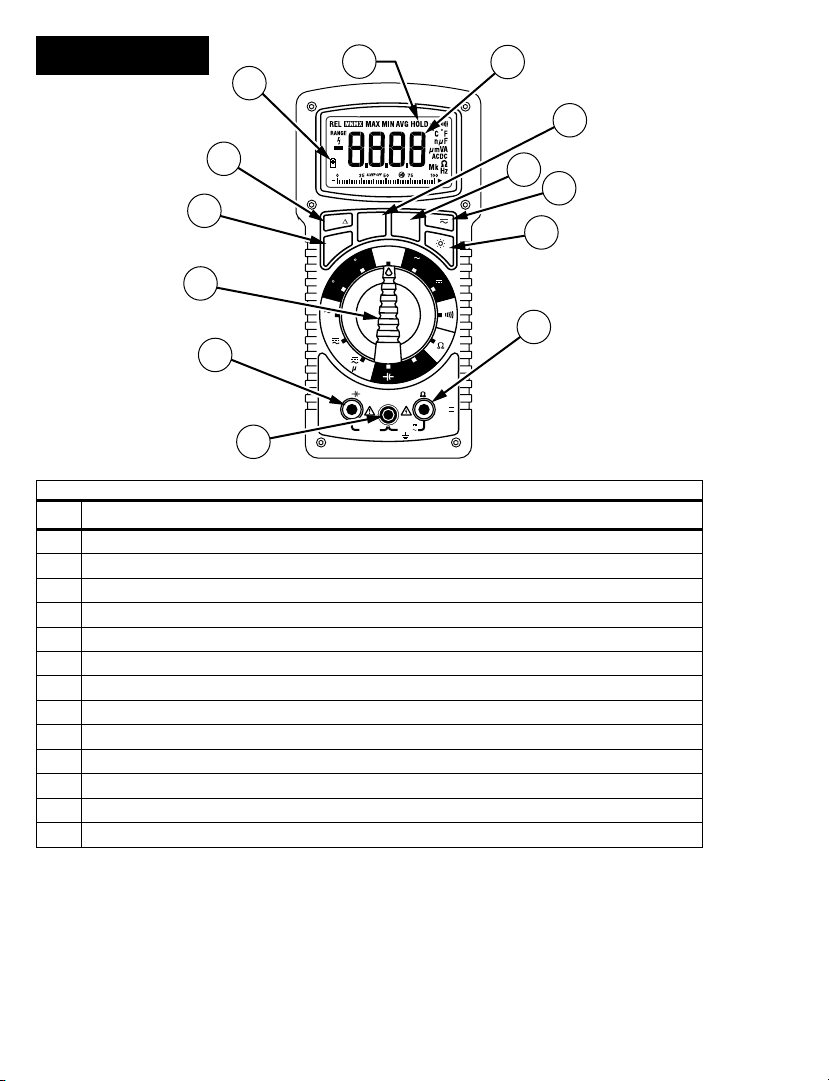
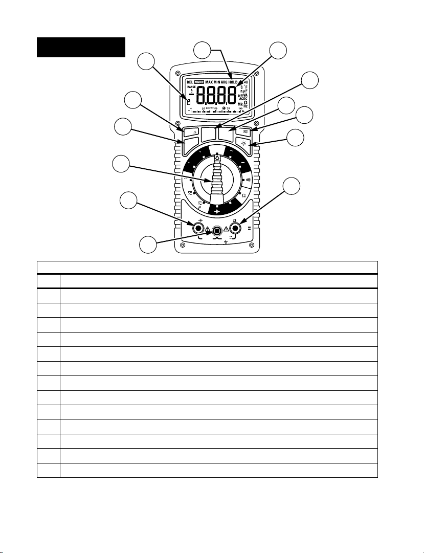
# Description
1 COM Input - common or low input for all measurements
2 Current and Capacitance Input
3 Function/Range Selector Switch
4 MIN MAX AVG Button
5 RELative Button
6 Low Battery Indicator
7 Hold Indicator
8 4-Digit LCD with measurement indicators
9 Data HOLD Button
10 RANGE Lock Button
11 AC DC Selection Button for Current Ranges
12 Backlight Button
13 Temperature, Volts, Ohms, and Frequency Input
Page 7

HD160C
Contents
Symbols .........................................................................................................................................2
Introduction ..................................................................................................................................2
Warnings and Precautions ...........................................................................................................2
Unpacking and Contents .............................................................................................................3
Display Symbols and Audible Symbols ........................................................................................4
Overload Condition ......................................................................................................................4
Incorrect Input Warning ..............................................................................................................4
Dangerous Voltage Warning .......................................................................................................4
Audible Feedback .........................................................................................................................4
Analog Bargraph ..........................................................................................................................5
Disable Beeper and Auto-Power Off ..........................................................................................5
Measuring Procedures .................................................................................................................5
Measuring DC Voltage (See Figure 1) ......................................................................................... 5
Measuring AC Voltage - True rms (See Figure 2) ........................................................................6
True rms AC Measurements .........................................................................................................6
Measuring DC Current (See Figure 3) .........................................................................................7
Measuring AC Current - True rms (See Figure 4) ........................................................................7
Continuity Test (See Figure 5) ......................................................................................................8
Resistance Measurement (See Figure 6) .....................................................................................8
Measuring Capacitance (See Figure 7) ........................................................................................9
Measuring Frequency (See Figure 8) ...........................................................................................9
Measuring Temperature (See Figure 9) ......................................................................................9
Button Functions ........................................................................................................................ 10
RANGE.......................................................................................................................................10
HOLD .........................................................................................................................................10
REL (Relative Measurements) .................................................................................................10
MIN MAX AVG ..........................................................................................................................11
Auto-Power Off ..........................................................................................................................11
Safety Test Leads ........................................................................................................................11
Specifications ..............................................................................................................................12
General Specifications..............................................................................................................12
Electrical Specifications ............................................................................................................12
DC Volts ............................................................................................................................12
AC Volts True rms ............................................................................................................13
DC Current .......................................................................................................................13
AC Current True rms ........................................................................................................ 13
Resistance .........................................................................................................................13
Continuity Test .................................................................................................................13
Capacitance ...................................................................................................................... 13
Temperature .................................................................................................................... 13
Frequency ......................................................................................................................... 13
Optional Accessories ................................................................................................................13
Maintenance and Repair ...........................................................................................................14
Battery/Fuse Replacement (Figure 10) ......................................................................................14
Repair Information .....................................................................................................................15
Heavy-Duty True-rms Digital Multimeter
1
Page 8
Symbols
Battery
B
Double insulated
Direct Current
Alternating Current
Fuse
Conforms to relevant Australian
standards.
Do not dispose of this product as unsorted municipal waste. Contact
Amprobe or a qualified recycler for disposal.
Refer to the manual
Dangerous Voltage
Earth Ground
Audible tone
Complies with EU directives
Canadian Standards Association.
®
[Note: Canadian and US.]
Introduction
The Amprobe digital multimeter HD160C is a heavy-duty 4-digit, autoranging, AC-coupled
True rms measuring instrument that measures voltage, current, resistance, continuity, as
well as capacitance, frequency and temperature. It also offers Range Lock, Data Hold,
Relative Measurement, Auto Min Max Measurement, a bright backlight, and Auto Power
Off to save battery life. The instrument is completely o-ring sealed to pass strict IP-67
ratings for moisture and dust proof. The HD160C also has internal components shock mounted for drop proof capability. The HD160C meets the highest safety rating of CAT IV
1000 V (1500V DC max).
Warnings and Precautions
This instrument is EN61010-1 certified for Cat IV, 1000 V ac/1500 V dc and lower
installations. Based on EN61010-1 transient requirements, this product should
only be used in installations where transients do not exceed 12,000 volts (a 1.2
µS/50 µS pulse).
• All inputs are protected against overload conditions up to the limits of each
function's stated input protection (see specifications). Never exceed these
limits or the ratings marked on the instrument itself.
• Exercise extreme caution when: measuring voltage >20 V, current >10 mA, ac
power line with inductive loads, ac power line during electrical storms. High
voltages can be lethal and high voltage transients may occur at any time.
• Operator injury or damage to the multimeter may occur during current
measurements if the fuse blows in a circuit with open circuit voltage 1000 V
ac/1500 V dc.
2
Page 9

• Always inspect your DMM, test leads and accessories for signs of damage or
abnormality before use. If an abnormal condition exists (broken or damaged
test leads, cracked case, display not reading, etc.), do not use. All internal
battery and fuse covers are integral to the EN61010-1 Cat IV safety rating and
must be in place to avoid potential shock hazards.
• When testing for voltage or current, make sure these ranges function correctly.
Take a reading of a known voltage or current first.
• Never ground yourself when taking measurements. Do not touch exposed
metal pipes, outlets, fixtures, etc., which might be at ground potential. Keep
your body isolated from ground and never touch exposed wiring, connections,
test probe tips, or any live circuit conductors. Do not use the Flex-Strap to
attach the meter to your body.
• Always measure current in series with the load – NEVER connect the
multimeter ACROSS a voltage source. Check fuse first.
• Never replace a fuse with one of a different rating.
• Do not operate instrument in an explosive atmosphere (flammable gases,
fumes, vapor, dust.)
• Do not use this or any piece of test equipment without proper training
• CRT SERVICE SAFETY REMINDER: A potential danger exists when measuring
voltages in the horizontal output and damper stages of CRT equipment. (High
voltage transients greater than 8000 V). Refer to your CRT service manual for
proper servicing instructions.
Unpacking and Contents
Your shipping carton should include the HD160C multimeter, a holster with Magna-Grip,
one test lead set with alligator clips(one black, one red), one temperature adaptor, one
Type K thermocouple probe, one 9 V battery (installed), a hex wrench (held inside holster)
and this manual. If any of the items are damaged or missing, immediately return the
complete package to the place of purchase for an exchange. The holster/tilt stand provides
additional protection of the meter from accidental falls and provides greater ease of
use. Both test lead probes can be attached to the holster for storage. One probe can be
attached for measurement, holding the meter with probe in one hand and the second
probe in the other hand.
3
Page 10

Display Symbols and Audible Symbols
Dangerous voltage warning (also double beep tone). Indicates input
voltages higher than 30 V ac or 60 V dc.
Low-battery voltage
B
- Negative polarity indicator
Overload Condition
Input Overload (highest range in autoranging) is indicated by “OL or -OL” and a
continuous tone. Remove test leads from the measurement setup as the input is beyond
the range of the meter.
Display Overload (input exceeds the selected range while range is locked) is also indicated
by “OL or -OL”. Select the next higher range until a value is displayed, or return to
autoranging. If overload still exists in the highest range, remove test leads from the
measurement setup as input is beyond the range of the meter.
Note: In both instances, overload indication is normal in the ohms and continuity ranges
(no sound) when the leads are not connected to anything or when the measured value is
higher than the selected resistance range.
Incorrect Input Warning
The meter displays a function error code “Err” when a test lead is placed in the A input
jack and the Selector switch is not set to a current or capacitance range. (If the meter is
connected to a voltage source with leads connected for current, very high current could
result). All current ranges are protected with a fast acting fuse.
Dangerous Voltage Warning
Displayed voltage warning and double-beep warning when input voltages are greater than
30 V ac/60 V dc, .
Audible Feedback
The meter emits a single beep when a parameter is changed, a “valid” front panel button
is pushed, or Auto Min Max values are updated. A double beep indicates a dangerous input
voltage (>30 V ac or 60 V dc).
The meter emits a continuous tone in the case of input overload, for continuity
measurement when resistance is <40Ω, and for current measurements, when the A input is
used and the current
exceeds 2 A.
4
Page 11

Analog Bargraph
The 41 segment analog bargraph indicates the percentage of the range the displayed
measurement relates to. The zero segment is lit when the instrument is turned on. Each
segment after that equals 2.5 % of range. The 400 mA, 40 MΩ, and Capacitance ranges are
limited to 16 segments.
Example: a 500 mV input in the 1 V range (50 %) is represented by 21 segments (50).
400mA (of a theoretical 1000 mA range) = 16 segments (40 %).
Disable Beeper and Auto-Power Off
You can disable the beeper and Auto Power Off by pressing and holding the REL button
while turning the meter ON.
Measuring Procedures
• Turn instrument on by turning function/range switch away from OFF and
selecting the parameter you want to measure.
• This instrument is autoranging on all ranges. It automatically selects the range
that gives the best resolution for the measured value. A range can be locked
through menu selection (see Button Functions, later in this manual). You
can tell which range you are in by the position of the decimal point and the
measurement unit displayed.
• When connecting or disconnecting test leads to a circuit, always turn off power
to device or circuit being tested and discharge all capacitors.
• Strictly observe the max input limits.
• Do not change functions while test leads are connected to circuit.
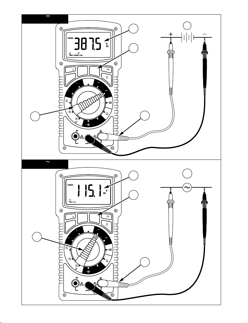
Measuring DC Voltage (See Figure 1)
1. Set the Function Switch to .
2. If
RANGE is displayed, press the RANGE button to enable auto ranging.
3. Connect the test leads: Red to
4. Connect the test leads to the circuit test points.
5. Read the display, and, if necessary, correct any overload (OL) conditions.
Temp VΩHz, Black to COM
5
Page 12
Measuring AC Voltage - True rms (See Figure 2)
5.0
4.0
3.0
2.5
1.0
2%
0%
5%
4%
3%
100%806040200
Wave form,Crest Factor
Additional correction from 1.5 to 5.0
Input RMS, Percentage of Full-Scale
1. Set the Function Switch to .
2. If
RANGE is displayed, press the RANGE button to enable auto ranging.
3. Connect the test leads: Red to
4. Connect the test leads to the circuit test points.
5. Read the display, and, if necessary, correct any overload (OL) conditions.
Temp VΩHz, Black to COM
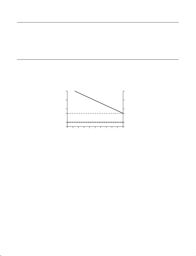
True rms AC Measurements
Model HD160C is an ac-coupled True rms measuring meter. It measures the True rms value
of distorted AC voltage or current signals. The Crest Factor handling capability is shown in
Table 1. The Crest Factor is the Peak Voltage divided by the rms voltage.
Table 1 - Crest Factor Handling Capability
Note: To accurately measure a DC voltage with an AC component, measure the AC
component first with selector switch set to . Note the measurement and range used.
Switch to , activate Range Lock (see Button Functions later in this manual) and select a
range equal to or higher then the range used previously. Note the measurement. The
result is the measured AC Voltage on top of the measured DC component. (Max input is
1500 V dc or 1000 V ac).
6
Page 13

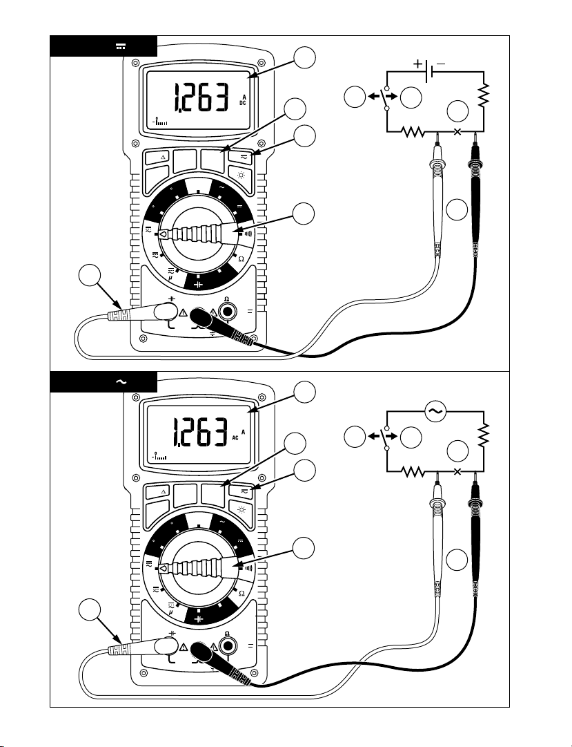
Measuring DC Current (See Figure 3)
1. Set the Function Switch to a current function, µA, mA, or 2A.
2. If AC is displayed, press the
3. If the 2A function is not selected and
to enable auto ranging.
4. Connect the test leads: Red to
5. Turn off power to the circuit being measured.
6. Open the circuit (-X-) in which current is to be measured (voltage between this
point and ground must not exceed 1500 V dc).
7. Securely connect test leads in series with the load.
8. Turn on power to the circuit being measured.
9. Read the display, and, if necessary, correct any overload (OL or -OL) conditions.
A button to turn on DC.
RANGE is displayed, press the RANGE button
A, Black to COM.
Measuring AC Current - True rms (See Figure 4)
1. Set the Function Switch to a current function, µA, mA, or 2A.
2. If DC is displayed, press the
3. If the 2A function is not selected and
to enable auto ranging.
4. Connect the test leads: Red to
5. Turn off power to the circuit being measured.
6. Open the circuit (-X-) in which current is to be measured (voltage between this
point and ground must not exceed 1000 V ac).
7. Securely connect test leads in series with the load.
8. Turn on power to the circuit being measured.
9. Read the display, and, if necessary, correct any overload (OL) conditions.
A button to turn on AC.
RANGE is displayed, press the RANGE button
A, Black to COM.
7
Page 14

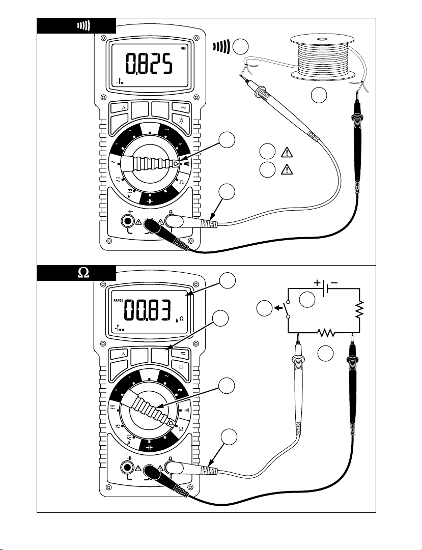
Continuity Test (See Figure 5)
1. Set the Function Switch to .
2. Connect the test leads: Red to
3. Turn off power to the circuit being measured.
4. Discharge any capacitors that may influence the reading.
5. Connect the test leads across the resistance.
6. Listen for the tone that indicates continuity (< 40
When measuring continuity the meter emits a continuous tone when the resistance value
falls below 40Ω.
Temp VΩHz, Black to COM.
Ω).
Resistance Measurement (See Figure 6)
1. Set the Function Switch to Ω.
2. If
RANGE is displayed, press the RANGE button to enable auto ranging.
3. Connect the test leads. Red to
4. Turn off power to the circuit being measured. Never measure resistance across a
voltage source or on a powered circuit.
5. Discharge any capacitors that may influence the reading.
6. Connect the test leads across the resistance.
7. Read the display. If OL appears on the highest range, the resistance is too large to
be measured.
Temp VΩHz, Black to COM.
Note: When measuring very low resistances, use Relative Measurement to eliminate the
test lead resistance (see Button Functions later in this manual).
8
Page 15

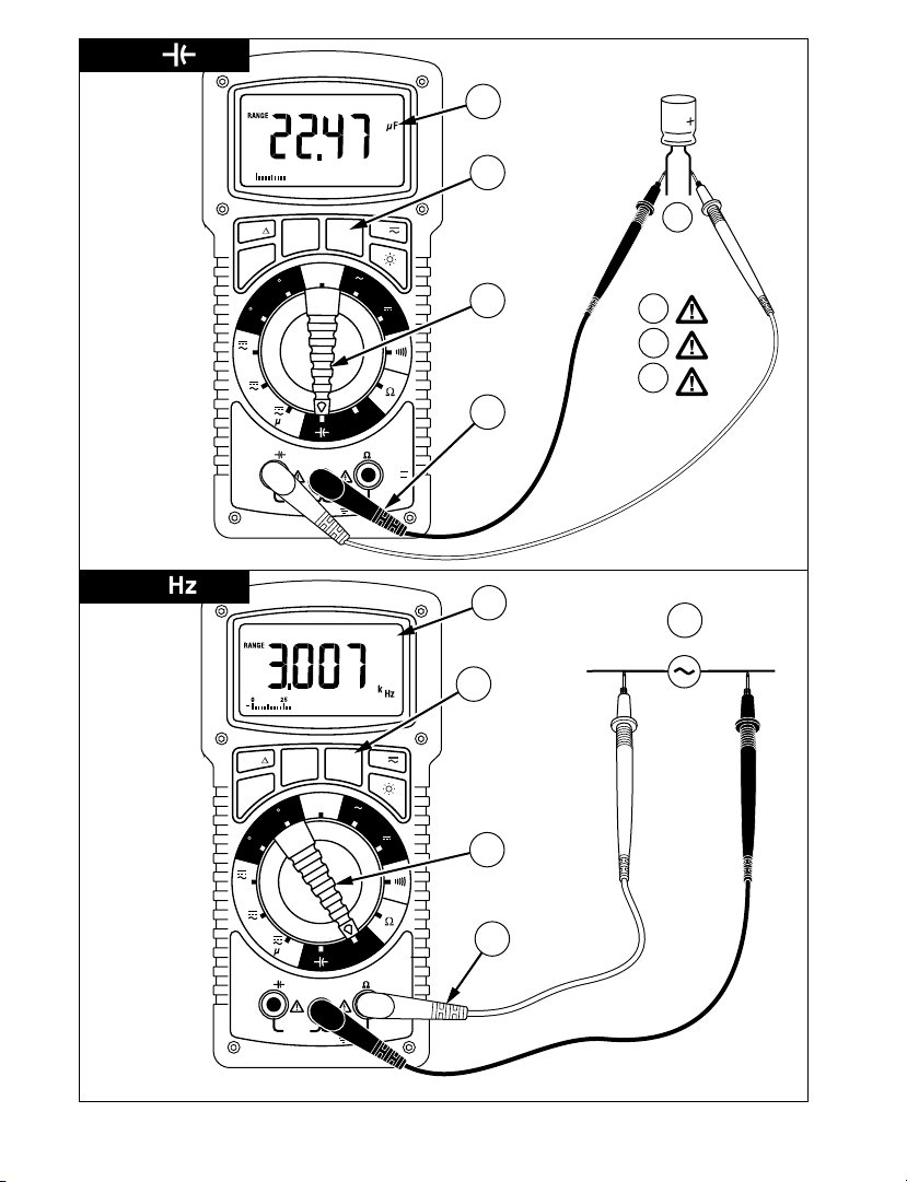
Measuring Capacitance (See Figure 7)
1. Set the Function Switch to the function.
2. If
RANGE is displayed, press the RANGE button to enable auto ranging.
3. Connect the test leads: Red to
4. Turn off power to the circuit being measured.
5. Discharge the capacitor using a 100 k
6. Free at least one end of the capacitor from the circuit.
7. Connect the test leads across the capacitor. When measuring an electrolytic
capacitor match the test lead polarity to the polarity of the capacitor.
8. Read the display.
COM, Black to A.
Ω resistor.
Measuring Frequency (See Figure 8)
1. Set the Function Switch to Hz.
2. If
RANGE is displayed, press the RANGE button to enable auto ranging.
3. Connect the test leads: Red to
4. Connect the test leads to the signal source.
5. Read the display.
Temp VΩHz, Black to COM.
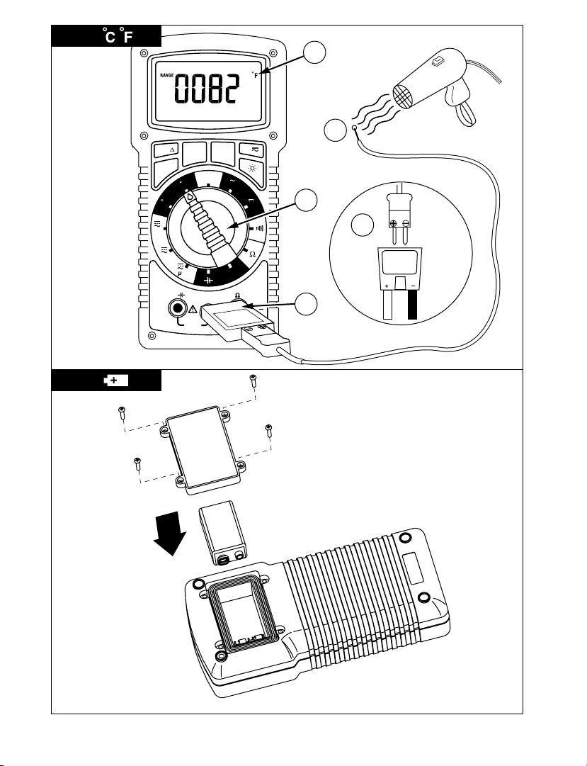
Measuring Temperature (See Figure 9)
1. Set the Function Switch to °C or °F.
2. Connect the K-type thermocouple to a TEMP adapter (TA-1A); match the polarity
of the adapter to the polarity of the thermocouple.
3. Connect the TEMP adapter to the
Note: The HD160C is compatible with all K-type thermocouples. The K-type bead
thermocouple supplied with the meter is not intended for contact with liquids or
electrical circuits.
4. Expose the thermocouple to the temperature to be measured.
5. Read the display.
Temp VΩHz and COM inputs.
9
Page 16
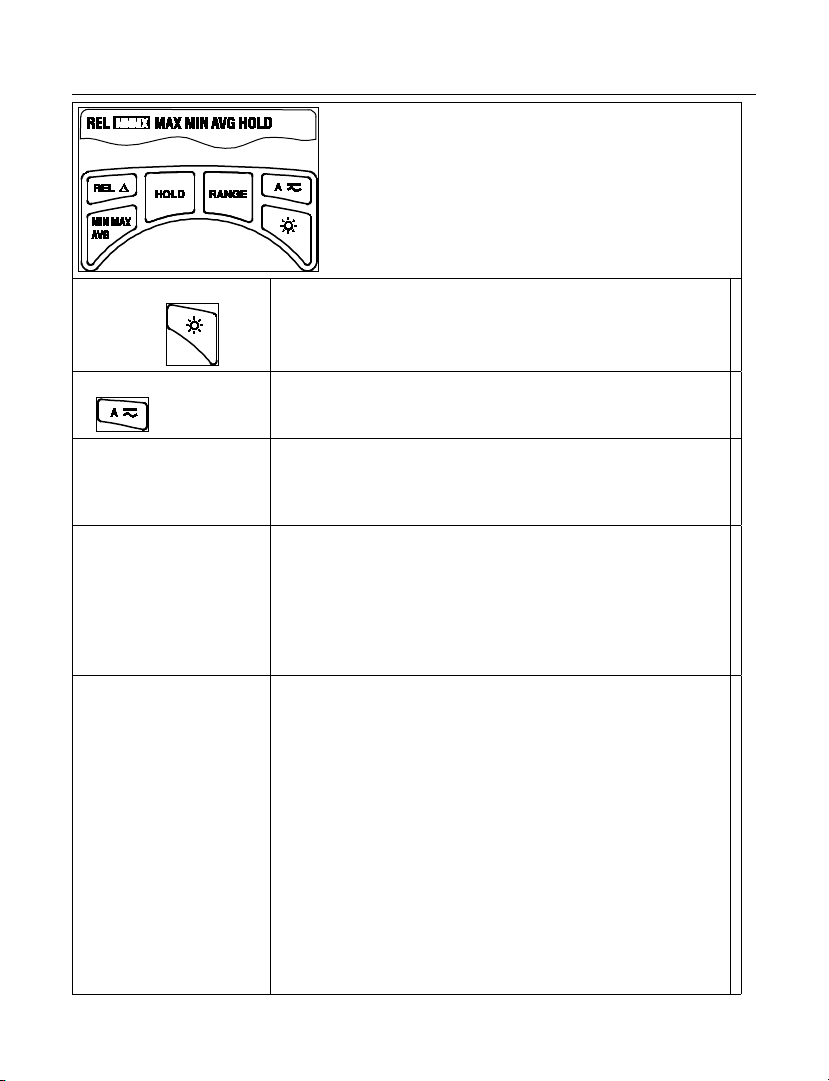
Button Functions
Display Backlight
Button
AC DC Mode
RANGE
HOLD
REL
(Relative Measurements)
Model HD160C has Digi-GloTM backlighting, one of the best
backlights available in the industry. This button turns the
backlight on and off. To conserve battery life, backlight will
automatically turn off after approximately 60 seconds.
Each press alternately selects the AC or DC mode for the
current function. The selected mode appears on the display
above the button.
Locks the currently displayed range. Each subsequent push
of the button moves to a higher range. From highest range,
the meter returns to the lowest range. The meter functions
in the 4000 count mode when range is locked.
Freezes the reading present on the LCD at the moment
the button is pressed. To use this button feature set up the
meter for the type of measurement and range desired.
Connect the test leads to the circuit/component to be
measured, then press Hold. The LCD reading will freeze and
display “HOLD.” You may now remove the test leads and
the reading will not change until you press Hold again.
The Relative mode displays the difference between the
actual reading and a reference value. It may be used with
any function or range; however, the range must be set
manually. To make a relative measurement first establish
a reference value by measuring a value and then pressing
the REL button after the reading has stabilized. This stores
the measured value as the reference and sets the display
to zero. The meter subtracts the reference value from
subsequent measurements and displays this difference as
the relative value. Measurement values greater than the
reference value will be positive and values less than the
reference value will be negative. To exit the Relative Mode,
Press and hold the REL button for 2 seconds. Select the
proper Range using the RANGE button before enabling the
REL feature. This function will not autorange.
10
Page 17

The MIN MAX AVG feature reads and updates the display
to show the maximum, minimum, or average value
measured after you press the MIN MAX AVG button.
Pressing the MIN MAX AVG button for less than 1 second
will put the meter into a mode of displaying the maximum,
MIN MAX AVG
Button Display Value Displayed
MNMX MAX Maximum value after feature activated
< 1 second MNMX MIN Minimum value after feature activated
< 1 second MNMX AVG Average value after feature is activated
< 1 second MNMX Actual reading, min max being recorded.
> 2 seconds
Exit MIN MAX
AVG
minimum, average, or actual readings. Each time the
button is pressed, the meter will cycle to the next display
mode as shown in the table below. Press the MIN MAX AVG
button for more than 2 seconds to disable this feature.
Select the proper Range using the RANGE button before
enabling the MIN MAX AVG feature.
This function will not autorange.
Normal measurement, actual reading
Auto-Power Off
In order to save battery life, your multimeter powers down automatically after
approximately 30 minutes of inactivity. You can turn it back on by turning the function
selector switch to OFF and back to a measuring function. The instrument does not power
down while in Max MIN AVG mode. You can disable Auto Power Off by pressing and
holding the MAX MIN AVG button while turning the meter ON.
Safety Test Leads
The test leads provided with your HD160C meter have shrouded banana plugs to eliminate
the possibility of shock if the plugs accidentally pull out of the meter while making a
measurement. Each set of test leads includes a pair of threaded alligator clips for secure
attachment to the probe tips. Replacement part number for Safety test leads is TL1500.
11
Page 18

Specifications
General Specifications
Display: 4 digit LCD, 9999 counts, with
annunciators, menu features and 41 segment
bargraph.
Polarity Indication: Automatic
Input overload indication: OL, -OL.
Low Battery Indication: B; less than 50 hours
battery life remain, accuracy is no longer
guaranteed
Display Update Rate: 2/sec, nominal; 20/sec for
bargraph.
Oper. Temp. 0 °C to +50 °C @ 0 to 75 % R.H.
Storage Temp: -20 °C to 60 °C @ 0 to 80 % RH,
battery removed
Altitude: 2000 meters - indoor/outdoor use
Temperature coefficient: 0.1 x (spec. accuracy)/
°C (0 °C to 18 °C and 28 °C to 50 °C)
Fuse: F 2 A/1500 V fuse (8 mm x 65 mm),
I.R. 30 kA – Amprobe p/n FP700
Power: Standard 9-volt battery, NEDA 1604, JIS
006P, IEC 6F22
Auto Power-Down: Meter powers down after
approximately 30 minutes of inactivity. Not in
Min/Max function.
Battery Life (typical): 150 hours, alkaline.
Backlight usage consumes extra power and will
decrease battery life significantly. Backlight
auto-off after approx. 60 seconds.
Dimensions, without holster (H x W x D): 200
x102 x59 mm (7.9 in x 4. 0 in x 2.3 in)
Weight (incl. battery): 642 g (22 oz)
Accessories: Heavy Duty Test leads with
threaded alligator clips, battery (installed),
hex wrench (inside holster), Holster with
Magne-Grip strap, Type K thermocouple probe
(TP255A), Temperature Adaptor (TA-1A) and
User Manual.
Case material: Reinforced, high-impact, fire
retardant thermoplastic
Safety: Meets EN 61010-1 Cat IV -1500 V dc or
1000 V ac. Class II. EN 60529:IP67
EMC: Meets EN 61326-1
EMC: This product complies with
requirements of the following European
Community Directives: 89/336/EEC
(Electromagnetic Compatibility) and 73/23/EEC
(Low Voltage) as amended by 93/68/EEC (CE
Marking). However, electrical noise or intense
electromagnetic fields in the vicinity of the
equipment may disturb the measurement
circuit. Measuring instruments will also respond
to unwanted signals that may be present within
the measurement circuit. Users should exercise
care and take appropriate precautions to avoid
misleading results when making measurements
in the presence of electronic interference.
Electrical Specifications
Accuracy at 23 °C ± 5 °C, <75 % RH, guaranteed
for one year.
DC Volts
Ranges: 1000 mV, 10 V, 100 V, 1500 V
Resolution: 0.1 mV in 1000 mV range:
Accuracy: ±(0.1 % rdg + 5 dgt)
Input Impedance: 10 MΩ
CMRR: >120 dB up to 1500 V dc
NMRR: >60 dB at 50 or 60 Hz
OL Protection: 1500 V dc or 1000 V ac rms.
Transient protection: 12 kV impulse (1.2
µS/50 µS) based on EN 61010-1:2001 impulse
requirement for at CAT IV 1000 V/1500V dc
product. This product should not be used in
installations where transients exceed 12 kV.
AC Volts True rms
Ranges: 1000 mV, 10 V, 100 V, 1000 V
Resolution: 0.1 mV in 1000 mV range
Accuracy:
1000 mV (45 Hz to 400 Hz)
±(1.2 % rdg + 10 dgt)
10 V, 100 V (45 Hz to 500 Hz)
±(1.2 % rdg + 10 dgt)
10 V, 100 V (500 Hz to 2 kHz)
±(2.0 % rdg + 10 dgt)
1000 V (45 Hz to 1 kHz)
±(2.0 % rdg + 10 dgt)
Input Impedance: 10 MΩ
Conversion type: True rms, ac coupled 5 % to
100 % of range
Crest factor: ≤ 3
OL Protection: 1500 V dc or 1000 V ac rms
Transient protection: 12 kV impulse (1.2
µS/50 µS) based on EN 61010-1:2001 impulse
requirement for at CAT IV 1000 V product. This
product should not be used in installations
where transients exceed 12 kV
12
Page 19

DC Current
Ranges: 100 µA, 1000 µA, 10mA, 100mA,
400mA, 2A (Auto/Manual ranging)
Resolution: 0.01µA in 100 µA range
Accuracy:
100 µA range; ± (0.5% rdg + 10 dgts)
1000 µA to 400 mA ranges: ± (0.5% rdg + 5
dgts)
2 A ±(1.5% rdg + 10 dgts)range
Input protection: 2 A/1500 V fast blow ceramic
fuse 8×65 mm on A input , FP700
Burden voltage: µA range of 1 mV/1 µA, mA
range of 10 mV/1 mA, 2A range of 500 mV/1A,
500 mV max. (2 V max. on 1000 µA, 100 mA,
400 mA, 2 A ranges)
AC Current True rms
Ranges: 100 µA, 1000 µA, 10 mA, 100 mA,
400 mA, 2 A
Resolution: 0.01 µA in 100 µA range
Accuracy( 45 Hz to 1kHz):
100 µA to 100 mA: ± (1.5 % + 10 dgts)
400 mA: ± (2.0 % + 10 dgts)
2 A: ± (2.5 % + 20 dgts)
Voltage burden: see DC Current
Conversion type: True rms ac coupled 10 to
100% of range
Crest factor: ≤ 3
OL protection: see DC Current.
Resistance
Ranges:1000 Ω, 10 kΩ, 100 kΩ, 1000 kΩ,
10 MΩ, 40 MΩ
Resolution: 0.1 Ω in 1000 Ω range
Accuracy:
1000 Ω to 1000 KΩ ranges: ±(0.5 % rdg
+8 dgts);
10 MΩ range: ± (1.0 % rdg +10 dgts)
40 MΩ range: ± (2.0 % rdg +10 dgts)
Overload protection, all ranges: 1500 V dc
or 1000 V ac rms
Continuity Test
Audible indication: Less than 40 Ω
Response time: 100 ms
Overload protection:1500 V dc or 1000 V ac rms
Capacitance
Ranges: 40 ηF, 400 ηF, 4 µF, 40 µF, 400 uF (3999
counts) ( Auto/Manual ranging )
Resolution: 0.01 ηF
Accuracy: ±(3.0% rdg +10dgts) on 40 ηF, 400 µF
ranges
±(3.0% rdg +5dgts) on 400 ηF to 40 µF ranges
Test voltange: < 1 V
Test Frequency: 1.3 Hz on 40 ηF to 40 µF ranges;
0.7 Hz on 400 µF range
Overload protection: 1500 V dc or 1000 V ac rms
Temperature
Ranges: -20 °C ~ 1300 °C (-4° F ~ 2372 °F) 3999
counts
Resolution: 1 °C, 1 °F
Accuracy: ±(2.0% rdg +4 °C) -20 °C ~ 10 °C
±(1.0% rdg +3 °C)10 °C ~ 200 °C
±(2.0% rdg + 2 °C) 200 °C ~ 1300 °C
±(2.0% rdg + 8 °F) -4 °F ~ 50 °F
±(1.0% rdg + 6 °F) 50° F ~ 400 °F
±(2.0% rdg +4 °F)400 °F ~2372 °F
Overload protection: 1500 V dc or 1000 V ac rms
Frequency
Ranges: 100Hz, 1000Hz, 10kHz, 100kHz,
1000kHz, 10MHz
Resolution: 0.01 Hz on 100 Hz range
Accuracy: ±(0.1% rdg + 5 dgts)
Sensitivity:
3 Hz to 1 MHz: >2.5 V ac rms;
1MHz to 10MHz: >2.5V ac rms, <5V ac rms
Minimum input range:
100 Hz range >3 Hz;
1000 Hz range >30 Hz
Minimum pulse width: > 25 ns
Duty cycle limits: > 30 % and < 70 %
Overload protection: 1500 V dc or 1000 V ac rms
Optional Accessories
TL1500 Test Leads with Alligator Clips
CT235A 1000 A ac/dc Clamp
CT237A 200 A ac/dc Current Clamp
CT238A 20 A ac/dc Current Clamp
VC221B Padded Vinyl Case. Fits meter & holster.
DC205C Deluxe Hard-Shell Carry Case
DC207C Large Deluxe Hard-Shell Carry Case
with extra space for accessories
HV231-10A High Voltage Probe
FP 700 Replacement Fuse, 2 A/1500 V
TA-1A K-type thermocouple, temperature
adapter.
13
Page 20

Maintenance and Repair
If there appears to be a malfunction during the operation of the meter, the following steps
should be performed in order to isolate the cause of the problem:
1. Check the battery.
2. Review the operating instructions for possible mistakes in operating procedure.
3. Inspect and test the test leads for a broken or intermittent connection.
4. Inspect and test the fuses. See Battery/Fuse Replacement for additional
information.
Except for the replacement of the battery or fuse, or test probes, repair of the multimeter
should be performed only by a Factory Authorized Service Center or by other qualified
instrument service personnel. The front panel and case can be cleaned with a mild solution
of detergent and water. Apply sparingly with a soft cloth and allow to dry completely
before using. Do not use aromatic hydrocarbons or chlorinated solvents for cleaning.
Battery/Fuse Replacement (Figure 10)
Warning
To prevent electrical shock or meter damage, disconnect the meter’s test leads from any
circuit and the meter then turn the meter off before removing the rear case cover.
PRECAUTIONS
• The hex head case screws each have a washer and gasket integral to the meter’s
water/dust-proof integrity. Upon opening, be sure these are retained and replaced
when closing.
• Prying the rear case cover off with a knife or screwdriver is not recommended as this
may damage the case rim flanging and/or gasket thereby destroying the water/dustproof integrity.
• The fuse cover is integral to the EN 61010-1 Cat IV safety rating and must be replaced
to avoid potential shock hazards.
• Battery or fuse replacement should be performed in a clean environment and with
appropriate care taken to avoid contaminating the meter’s interior components.
• There are no user serviceable parts or components on the circuit boards. Disassembly
beyond the instructions list below for battery and/or fuse replacement will void all
warranties.
BATTERY REPLACEMENT
Disconnect the test leads, turn off the meter and remove the holster. Remove the 4 hex head
battery cover screws from the rear case cover using the 2 mm hex wrench as Shown in Figure
10. Replace the battery with a NEDA type1604 or equivalent 9V alkaline battery. Make sure the
battery compartment seal is in good condition and properly aligned before replacing the
cover and screws.
FUSE REPLACEMENT
The fuse is located under the protective cover. Disconnect the test leads, turn off the meter
and remove the holster. Remove the six hex head screws in the face plate using the 2 mm hex
wrench mounted in holster. Remove the rear case cover carefully and place the front of the
14
Page 21

meter face down on a clean padded surface. Lift off cover and carefully remove the fuse by
gently prying under the fuse. Pry out the large fuse by placing a small flat screwdriver under the
fuse’s center using the circuit board edge toward the bottom of the meter as a fulcrum. Do NOT
use the gasket as a fulcrum point as this could permanently disfigure the gasket.
Warning
Use only the same size and type fuse specified. Use of higher amperage or lower voltage or different type fuses could result in
shock, injury and/or damage to the meter. Replacement fuse is:
2 A/1500 V fast blow ceramic size 8 x 65 mm. Amprobe p/n: FP700.
CLOSING THE BATTERY COMPARTMENT
After fuse replacement, replace the fuse cover and the rear case cover; be careful not to
bend or pinch the case rim gasket. Re-install the six hex-head screws with a gasket and
washer and tighten securely with an even amount of torque on each. Do NOT over tighten
as this may strip case threading. Turn on the meter and test operation. If working normally
replace the holster.
Repair Information
All test tools returned for warranty or non-warranty repair or for calibration should be accompanied
by the following: your name, company’s name, address, telephone number, and proof of purchase.
Additionally, please include a brief description of the problem or the service requested and include
the test leads with the meter. Non-warranty repair or replacement charges should be remitted in the
form of a check, a money order, credit card with expiration date, or a purchase order made payable to
Amprobe Test Tools.
In-Warranty Repairs and Replacement – All Countries
Please read the warranty statement and check your battery before requesting repair. During the
warranty period any defective test tool can be returned to your Amprobe Test Tools distributor for an
exchange for the same or like product. Please check the “Where to Buy” section on www.amprobe.com
for a list of distributors near you. Additionally, in the United States and Canada In-Warranty repair and
replacement units can also be sent to an Amprobe Test Tools Service Center (see below for address).
Non-Warranty Repairs and Replacement – US and Canada
Non-warranty repairs in the United States and Canada should be sent to an Amprobe Test Tools
Service Center. Call Amprobe Test Tools or inquire at your point of purchase for current repair and
replacement rates.
In USA In Canada
Amprobe Test Tools Amprobe Test Tools
Everett, WA 98203 Mississauga, ON L4Z 1X9
Tel: 877-AMPROBE (267-7623) Tel: 905-890-7600
Non-Warranty Repairs and Replacement – Europe
European non-warranty units can be replaced by your Amprobe Test Tools distributor for
a nominal charge. Please check the “Where to Buy” section on www.amprobe.com for a list
of distributors near you.
European Correspondence Address*
Amprobe
P.O. Box 1186
5602 BD Eindhoven
Test Tools Europe
The Netherlands
*(Correspondence only – no repair or replacement available from this address. European customers
please contact your distributor.)
15
Page 22
1
2
V
OFF
2 A
mA
A
V
V
Hz
F
C
REL
MIN MAX
AVG
RANGEHOLD
A
HD160C
V
A
Temp
COM
2A MAX
FUSED
MAX
1500V
1000V
IV
CAT
1000 V
Hz
OFF
2 A
mA
A
V
V
Hz
F
C
REL
MIN MAX
AVG
RANGEHOLD
A
HD160C
V
A
Temp
COM
2A MAX
FUSED
MAX
1500V
1000V
IV
CAT
1000 V
Hz
4
V
4
3
3
2
5
2
5
1
1
16
Page 23
3
4
A
A
OFF
2 A
mA
A
V
V
Hz
F
C
REL
MIN MAX
AVG
RANGEHOLD
A
HD160C
V
A
Temp
COM
2A MAX
FUSED
MAX
1500V
1000V
IV
CAT
1000 V
Hz
OFF
2 A
mA
A
V
V
Hz
F
C
REL
MIN MAX
AVG
RANGEHOLD
A
HD160C
V
A
Temp
COM
2A MAX
FUSED
MAX
1500V
1000V
IV
CAT
1000 V
Hz
5
8
5
7
4
8
6
7
9
2
3
1
5
1
4
9
2
3
17
Page 24
5
6
OFF
2 A
mA
A
V
V
Hz
F
C
REL
MIN MAX
AVG
RANGEHOLD
A
HD160C
V
A
Temp
COM
2A MAX
FUSED
MAX
1500V
1000V
IV
CAT
1000 V
Hz
OFF
2 A
mA
A
V
V
Hz
F
C
REL
MIN MAX
AVG
RANGEHOLD
A
HD160C
V
A
Temp
COM
2A MAX
FUSED
MAX
1500V
1000V
IV
CAT
1000 V
Hz
5
3
4
6
1
2
4
6
5
7
3
2
1
18
Page 25
7
8
OFF
2 A
mA
A
V
V
Hz
F
C
REL
MIN MAX
AVG
RANGEHOLD
A
HD160C
V
A
Temp
COM
2A MAX
FUSED
MAX
1500V
1000V
IV
CAT
1000 V
Hz
OFF
2 A
mA
A
V
V
Hz
F
C
REL
MIN MAX
AVG
RANGEHOLD
A
HD160C
V
A
Temp
COM
2A MAX
FUSED
MAX
1500V
1000V
IV
CAT
1000 V
Hz
5
6
7
4
4
5
3
2
1
1
2
8
3
19
Page 26
9
10
OFF
2 A
mA
A
V
V
Hz
F
C
REL
MIN MAX
AVG
RANGEHOLD
A
HD160C
V
A
Temp
COM
2A MAX
FUSED
MAX
1500V
1000V
IV
CAT
1000 V
Hz
K
1
5
4
3
2
20
Page 27

Page 28

Page 29

HD160C
Heavy-Duty True-rms
Digital Multimeter
Mode d’emploi
Francais
Page 30
HD160C
OFF
2 A
mA
A
V
V
Hz
F
C
REL
MIN MAX
AVG
RANGEHOLD
A
HD160C
V
A
Temp
COM
2A MAX
FUSED
MAX
1500V
1000V
IV
CAT
1000 V
Hz
1
2
3
4
5
6
7
8
9
10
11
12
13
# Description
1 Entrée COM – entrée faible ou commune de toutes les mesures
2 Entrée de capacité et de courant
3 Sélecteur de gamme/fonction
4 Touche MIN MAX MOY
5 Touche RELative
6 Indicateur de pile faible
7 Indicateur de maintien d’affichage
8 Ecran LCD à 4 chiffres avec indicateurs de mesure
9 Touche de maintien d’affichage
10 Verrouillage de gamme
11 Touche de sélection c.a./c.c. pour les gammes de courant
12 Touche de rétroéclairage
13 Entrée de température, volts, ohms et fréquence
Page 31

HD160C
Table des matières
Symboles ................................................................................................................................... 2
Introduction .............................................................................................................................. 2
Mises en garde et précautions ................................................................................................ 2
Déballage et vérification du contenu ..................................................................................... 3
Symboles d’affichage et symboles sonores ............................................................................. 4
Conditions de surcharge .......................................................................................................... 4
Signalement des entrées incorrectes ...................................................................................... 4
Signalement des tensions dangereuses .................................................................................. 4
Notification sonore .................................................................................................................. 4
Affichage incrémental analogique ......................................................................................... 5
Inactivation de l’avertisseur et mise en veille automatique .................................................. 5
Techniques de mesure .............................................................................................................. 5
Mesure de tension continue (voir Figure 1) ........................................................................... 5
Mesure efficace vraie (TRMS) d’une tension alternative (voir Figure 2) ............................... 6
Mesures efficaces vraies de courants alternatifs .................................................................... 6
Mesure de courant continu (voir Figure 3) ............................................................................. 7
Mesure efficace vraie (TRMS) d’un courant alternatif (voir Figure 4) .................................. 7
Test de continuité (voir Figure 5) ............................................................................................ 8
Mesure de résistance (voir Figure 6) ....................................................................................... 8
Mesure de capacité (voir Figure 7) .......................................................................................... 9
Mesure de fréquence (voir Figure 8) ....................................................................................... 9
Mesure de température (voir Figure 9) .................................................................................. 9
Fonctions des touches ............................................................................................................ 10
RANGE................................................................................................................................... 10
HOLD ..................................................................................................................................... 10
Mesures relatives (REL) ........................................................................................................ 10
MIN MAX AVG ...................................................................................................................... 11
Arrêt automatique ................................................................................................................. 11
Cordons de test de sécurité ................................................................................................... 11
Spécifications .......................................................................................................................... 12
Caractéristiques générales ................................................................................................... 12
Caractéristiques électriques ................................................................................................. 12
Volts c.c. ....................................................................................................................... 12
Mesure de tension c.a. (TRMS) ................................................................................... 13
Courant c.c. .................................................................................................................. 13
Mesure de courant c.a. (TRMS) ................................................................................... 13
Résistance ..................................................................................................................... 13
Test de continuité ........................................................................................................ 13
Capacité ....................................................................................................................... 13
Température ................................................................................................................ 13
Fréquence .................................................................................................................... 13
Accessoires en option ........................................................................................................... 13
Entretien et réparation .......................................................................................................... 14
Changement de la pile / des fusibles (voir Figure 10) .......................................................... 14
Informations sur les réparations ...........................................................................................15
Heavy-Duty True-rms Digital Multimeter
1
Page 32

Symboles
Batterie
B
Double isolation
Courant continu
Courant alternatif
Fusible
Conforme aux normes
australiennes pertinentes.
Ne pas mettre ce produit au rebut avec les déchets ménagers. Contacter
Amprobe ou un centre de recyclage qualifié pour sa mise au rebut.
Se reporter au mode d’emploi
Tension dangereuse
Prise de terre
Signal sonore
Conforme aux directives de l’UE
Association canadienne de
normalisation. [Remarque :
®
Canada
et Etats-Unis.]
Introduction
Le multimètre numérique TRMS HD160C d’Amprobe est un appareil de mesures efficaces
vraies couplées en courant alternatif à grand rendement, avec mode de gamme automatique,
4 chiffres de résolution. Il mesure la tension, le courant, la résistance, la continuité ainsi que
la capacité, la fréquence et la température. Il propose également le verrouillage de gamme,
le maintien des données affichées, la mesure relative, les mesures automatiques Min Max, un
écran lumineux rétroéclairé et la mise en veille automatique pour économiser la charge de la
pile. L’instrument est hermétiquement protégé par un joint torique selon les normes rigoureuses
IP-67 contre l’infiltration de l’humidité et des poussières. Les composants internes du HD160C
possèdent en outre une monture anti-vibration pour protéger l’appareil en cas de chute. Le
HD160C est compatible avec les normes de sécurité très strictes CAT IV 1000 V (1500V c.c. max.).
Mises en garde et précautions
Cet instrument est certifié EN61010-1 pour les installations Cat IV, 1000 V
c.a./1500 V c.c. et inférieures. Conformément aux caractéristiques de transitoires
EN61010-1, cet appareil ne doit être utilisé que si les transitoires dans les
installations ne dépassent pas 12 000 volts (une impulsion de 1,2 µS/50 µS).
• Toutes les entrées sont protégées contre les conditions de surcharge jusqu’aux
seuils de protection d’entrée déclarés de chaque fonction (voir Spécifications).
Ne jamais dépasser ces limites ou les valeurs nominales indiquées sur
l’instrument proprement dit.
• Faire preuve d’extrême prudence en : mesurant les tensions > 20 V, les
courants > 10 mA, les lignes d’alimentation secteur à charges inductives,
les lignes d’alimentation secteur pendant les orages électriques. Les hautes
tensions peuvent être mortelles et des transitoires à tension élevée peuvent se
produire à tout moment.
• L’opérateur risque d’être blessé et le multimètre d’être endommagé pendant
les mesures de courant si le fusible saute dans un circuit avec une tension en
circuit ouvert de 1000 V c.a./1500 V c.c.
2
Page 33

• Toujours inspecter le multimètre numérique, les cordons de mesure et les
accessoires pour détecter tout dommage ou anomalie avant l’emploi. Ne
pas utiliser l’instrument en présence d’une condition anormale (cordons de
mesure endommagés ou brisés, boîtier fissuré, affichage sans mesure, etc.).
Les capots internes de pile et de fusible font partie intégrante de la norme
de sécurité EN61010-1 Cat IV ; ils doivent être en place pour éviter les chocs
électriques potentiels.
• S’assurer que ces gammes fonctionnent correctement en testant les tensions
et les courants. Relever d’abord une mesure de courant ou de tension
connue.
• Ne jamais se relier à la terre en prenant des mesures. Ne pas toucher les
tuyaux métalliques exposés, les prises, les accessoires fixes, etc. qui peuvent
avoir un potentiel à la terre. Le corps de l’utilisateur doit être isolé de la
terre et ne jamais toucher les fils exposés, les branchements, les extrémités
des sondes ni aucun conducteur de circuit sous tension. Ne pas utiliser la
sangle flexible pour s’attacher l’appareil au corps.
• Toujours mesurer le courant en série avec la charge – ne JAMAIS connecter
le multimètre AUX BORNES d'une source de tension. Vérifier d’abord le
fusible.
• Ne jamais installer un fusible de calibre différent.
• Ne pas utiliser l'appareil dans une atmosphère explosible (gaz inflammables,
émanations, vapeurs ou poussières).
• Ne pas utiliser cet appareil ni aucun autre module de test sans avoir reçu la
formation adéquate.
• RAPPEL DE SECURITE SUR LE SERVICE DES TUBES CATHODIQUES : La mesure
de tensions dans les systèmes d’amortisseurs et le balayage horizontal des
équipements à tubes cathodiques pose un danger potentiel. (Transitoires de
tension élevée supérieurs à 8000 V). Reportez-vous au manuel de service des
tubes cathodiques pour les instructions d’intervention appropriées.
Déballage et vérification du contenu
Votre carton de livraison doit contenir le multimètre HD160C, un étui muni d’une sangle
Magna-Grip, un jeu de cordons de mesure avec pinces crocodiles (un noir, un rouge), un
adaptateur de température, une sonde thermocouple de type K, une pile 9 V (installée),
un clé hexagonale (maintenue dans l’étui) et ce manuel. Si l’un de ces éléments est
endommagé ou manquant, renvoyez immédiatement le contenu complet de l’emballage
au lieu d’achat pour l’échanger. La béquille ou l’étui protège l’appareil contre une chute
accidentelle et facilite son utilisation. Les deux sondes de test se fixent à l’étui pour leur
rangement. Une sonde peut être fixée pour les mesures, l’opérateur tenant l’appareil avec
la sonde d’une main et la deuxième sonde de l’autre.
3
Page 34

Symboles d’affichage et symboles sonores
Signalement de tension dangereuse (aussi tonalité à deux bips sonores).
Indique des tensions d’entrée supérieures à 30 V c.a. ou 60 V c.c.
Tension de pile faible
B
Indicateur de polarité négative
-
Conditions de surcharge
Une surcharge en entrée (gamme la plus élevée en mode automatique) est indiquée par
« OL » ou « -OL » et une tonalité continue. Retirez les cordons de mesure de l’installation
de mesure car l’entrée dépasse le calibre du multimètre.
L’affichage de la surcharge (l’entrée dépasse la gamme sélectionnée pendant le
verrouillage de gamme) est également indiqué par « OL » ou « -OL ». Sélectionnez la
gamme immédiatement supérieure jusqu’à l’apparition d’une valeur, ou revenez au mode
de gamme automatique. Si la surcharge persiste dans la gamme la plus élevée, retirez
les cordons de mesure de la configuration de mesure car l’entrée dépasse le calibre du
multimètre.
Remarque :
des résistances et de continuité (aucun son) lorsque les cordons ne sont connectés à aucun
élément ou lorsque la valeur mesurée est supérieure à la gamme de résistance sélectionnée.
Dans les deux cas, l’indication d’une surcharge est normale dans les gammes
Signalement des entrées incorrectes
Le multimètre affiche un code d’erreur de fonction « Err » lorsqu’un cordon de mesure est
introduit dans la prise d’entrée A si le sélecteur n’est pas réglé sur une gamme de capacité
ou de courant. (Une intensité très élevée risque de se produire si le multimètre est connecté
à une source de tension à l’aide des cordons placés pour une lecture de courant). Toutes les
gammes de courant sont protégées par un fusible instantané.
Signalement des tensions dangereuses
Signalement visuel de la tension et signalement à double tonalité si les tensions d’entrée
sont supérieures à 30 V c.a./60 V c.c., .
Notification sonore
Le multimètre émet une seule tonalité lorsqu’un paramètre est modifié, qu’une touche
« valable » de la face avant est activée ou que les valeurs Auto Min Max sont mises à jour.
Une double tonalité indique une tension d’entrée dangereuse (> 30 V c.a. ou 60 V c.c.).
Le multimètre émet une tonalité continue dans le cas d’une surcharge d’entrée, pour les
mesures de continuité lorsque la résistance est < 40
l’entrée A est utilisée et que le courant dépasse 2 A.
Ω, et pour les mesures de courant si
4
Page 35

Affichage incrémental analogique
Le graphe incrémental analogique à 41 segments indique à quel pourcentage de la gamme
la mesure affichée est apparentée. Le segment zéro est éclairé lorsque l’instrument est mis
sous tension. Chaque segment consécutif est égal à 2,5 % de la gamme. Les gammes de
capacité, 400 mA et 40 MΩ sont limitées à 16 segments.
Exemple : Une entrée de 500 mV dans la gamme 1 V (50 %) est représentée par 21
segments (50). 400 mA (d’une gamme théorique de 1000 mA) = 16 segments (40 %).
Inactivation de l’avertisseur et mise en veille automatique
Pour désactiver l’avertisseur et la mise en veille automatique, maintenez la touche REL
enfoncée tout en activant le multimètre.
Techniques de mesure
• Mettez l’instrument sous tension en éloignant le sélecteur de fonction/gamme de
la position OFF et en sélectionnant le paramètre à mesurer.
• Cet instrument établit automatiquement la gamme sur toutes les gammes. Il
sélectionne automatiquement la gamme qui fournit la meilleure résolution
pour la valeur mesurée. Une gamme peut être verrouillée à partir du menu
(voir Fonctions des touches plus loin dans ce manuel). Pour identifier la gamme
actuellement utilisée, repérez-vous à partir de la position du point décimal et de
l’unité de mesure affichée.
• En branchant ou en débranchant les cordons de mesure à un circuit, mettez
toujours l’appareil ou le circuit testé hors tension et déchargez tous les
condensateurs.
• Respectez rigoureusement les limites d’entrée maximales.
• Ne changez pas de fonctions alors que les cordons de mesure sont branchés au
circuit.
Mesure de tension continue (voir Figure 1)
1. Réglez le sélecteur de fonction sur .
2. Si le mot
de gamme automatique.
3. Branchez les cordons de test : Rouge à
4. Branchez les cordons de mesure aux points de test du circuit.
5. Lisez l’affichage et corrigez le cas échéant toute surcharge (OL).
RANGE apparaît, appuyez sur la touche RANGE pour activer le mode
Temp VΩHz, noir à COM.
5
Page 36

Mesure efficace vraie (TRMS) d’une tension alternative (voir Figure 2)
5.0
4.0
3.0
2.5
1.0
2%
0%
5%
4%
3%
100%806040200
Forme d'onde, Facteur Crête
Correction supplém. de 1.5 à 5.0
Entrée effective, % pleine échelle
1. Réglez le sélecteur de fonction sur .
2. Si le mot
de gamme automatique.
3. Branchez les cordons de test : Rouge à
4. Branchez les cordons de mesure aux points de test du circuit.
5. Lisez l’affichage et corrigez le cas échéant toute surcharge (OL).
RANGE apparaît, appuyez sur la touche RANGE pour activer le mode
Temp VΩHz, noir à COM.
Mesures efficaces vraies de courants alternatifs
Le modèle HD160C est un appareil de mesure efficace vraie couplé en courant alternatif. Il
mesure la valeur efficace vraie des signaux de courant et de tension alternatifs déformés.
La gestion du facteur de crête est indiquée dans le tableau 1. Le facteur de crête est la
tension maximum divisée par la tension efficace.
Tableau 1 – Gestion du facteur de crête
Remarque :
mesurez en premier la composante c.a. avec le sélecteur réglé sur . Notez la mesure et la
gamme utilisées. Basculez sur , activez le verrouillage de gamme (voir la section Fonctions
des touches plus loin dans ce manuel) et sélectionnez une gamme égale ou supérieure à
la gamme utilisée précédemment. Notez la mesure. Le résultat obtenu est la tension
alternative mesurée au-dessus de la composante c.c. mesurée. (Entrée max de 1500 V c.c. ou
de 1000 V c.a..)
Pour mesurer avec précision une tension continue avec une composante c.a.,
6
Page 37

Mesure de courant continu (voir Figure 3)
1. Réglez le sélecteur de fonction sur une mesure de courant µA, mA ou 2A.
2. Si le mot AC apparaît, appuyez sur la touche
3. Si
RANGE apparaît alors que la fonction 2A n’est pas sélectionnée, appuyez sur
la touche RANGE pour activer le mode de gamme automatique.
4. Branchez les cordons de test : Rouge à
5. Mettez hors tension le circuit à mesurer.
6. Coupez le circuit (-X-) sur lequel le courant doit être mesuré (la tension entre ce
point et la terre ne doit pas dépasser 1500 V c.c.).
7. Branchez solidement les cordons de mesure en série avec la charge.
8. Mettez sous tension le circuit à mesurer.
9. Lisez l’affichage et corrigez le cas échéant toute surcharge (OL).
A pour activer le mode DC.
A, noir à COM.
Mesure efficace vraie (TRMS) d’un courant alternatif (voir Figure 4)
1. Réglez le sélecteur de fonction sur une mesure de courant µA, mA ou 2A.
2. Si le mot DC apparaît, appuyez sur la touche
3. Si
RANGE apparaît alors que la fonction 2A n’est pas sélectionnée, appuyez sur
la touche RANGE pour activer le mode de gamme automatique.
4. Branchez les cordons de test : Rouge à
5. Mettez hors tension le circuit à mesurer.
6. Coupez le circuit (-X-) sur lequel le courant doit être mesuré (la tension entre ce
point et la terre ne doit pas dépasser 1000 V c.a.).
7. Branchez solidement les cordons de mesure en série avec la charge.
8. Mettez sous tension le circuit à mesurer.
9. Lisez l’affichage et corrigez le cas échéant toute surcharge (OL).
A pour activer le mode c.a..
A, noir à COM.
7
Page 38

Test de continuité (voir Figure 5)
1. Réglez le sélecteur de fonction sur .
2. Branchez les cordons de test : Rouge à
3. Mettez hors tension le circuit à mesurer.
4. Déchargez les condensateurs susceptibles d’influencer la lecture.
5. Branchez les sondes de test aux bornes de la résistance.
6. Notez la tonalité qui indique la continuité (< 40
En mesurant la continuité (aussi pour les diodes en court-circuit) le multimètre émet une
tonalité continue lorsque la résistance mesurée tombe en dessous de 40 Ω.
Temp VΩHz, noir à COM.
Ω).
Mesure de résistance (voir Figure 6)
1. Réglez le sélecteur de fonction sur Ω.
2. Si le mot
de gamme automatique.
3. Branchez les cordons de test. Rouge à
4. Mettez hors tension le circuit à mesurer. Ne mesurez jamais la résistance aux
bornes d’une source de tension sur un circuit alimenté.
5. Déchargez les condensateurs susceptibles d’influencer la lecture.
6. Branchez les sondes de test aux bornes de la résistance.
7. Lisez l’affichage. Si OL apparaît sur la gamme la plus élevée, la résistance est trop
grande pour être mesurée.
RANGE apparaît, appuyez sur la touche RANGE pour activer le mode
Temp VΩHz, noir à COM.
Remarque : Pour mesurer de très faibles résistances, utilisez la mesure relative pour
éliminer la résistance des cordons de test (voir Fonctions des touches plus loin dans ce
manuel).
8
Page 39

Mesure de capacité (voir Figure 7)
1. Réglez le sélecteur de fonction sur .
2. Si le mot
de gamme automatique.
3. Branchez les cordons de test : Rouge à
4. Mettez hors tension le circuit à mesurer.
5. Déchargez le condensateur dans une résistance de 100 k
6. Libérez du circuit au moins une extrémité du condensateur.
7. Reliez les cordons de mesure aux bornes du condensateur. Pour mesurer un
condensateur électrolytique, alignez la polarité du cordon de test sur celle du
condensateur.
8. Lisez l'affichage.
RANGE apparaît, appuyez sur la touche RANGE pour activer le mode
COM, noir à A.
Ω.
Mesure de fréquence (voir Figure 8)
1. Réglez le sélecteur de fonction sur Hz.
2. Si le mot
de gamme automatique.
3. Branchez les cordons de test : Rouge à
4. Branchez les cordons de mesure à la source du signal.
5. Lisez l’affichage.
RANGE apparaît, appuyez sur la touche RANGE pour activer le mode
Temp VΩHz, noir à COM.
Mesure de température (voir Figure 9)
1. Réglez le sélecteur de fonction sur °C ou °F.
2. Branchez le thermocouple de type K à un adaptateur TEMP (TA-1A) ; alignez la
polarité de l’adaptateur sur celle du thermocouple.
3. Branchez l’adaptateur TEMP aux entrées
Remarque : Le HD160C est compatible avec tous les thermocouples de type K. Le
thermocouple de type K à boule fourni avec le multimètre n’est pas conçu pour
entrer en contact avec l’eau ou les circuits électriques.
4. Exposez le thermocouple à la température à mesurer.
5. Lisez l’affichage.
Temp VΩHz et COM.
9
Page 40

Fonctions des touches
Touche de
rétroéclairage
Le modèle HD160C est équipé du rétroéclairage Digi-GloTM,
l’un des meilleurs systèmes de rétroéclairage commercialisé.
Cette touche active ou désactive le rétroéclairage.
Pour préserver la charge de la pile, le rétroéclairage est
automatiquement désactivé après environ 60 secondes.
Mode c.a. / c.c.
RANGE
HOLD
Mesures relatives (REL)
Chaque pression sélectionne alternativement le mode c.a.
ou c.c. pour la fonction de mesure de courant. Le mode
sélectionné apparaît sur l’écran au-dessus de la touche.
Verrouille la gamme actuellement affichée. Chaque
pression consécutive de cette touche permet de passer à
une gamme supérieure. Après avoir atteint la gamme la
plus élevée, le multimètre revient sur la gamme la plus
faible. Le multimètre fonctionne dans le mode de 4000
comptes lorsqu’une gamme est verrouillée.
Gèle la mesure affichée sur l’écran LCD lorsque cette
touche est activée. Pour utiliser cette fonction, configurez
le multimètre pour le type de mesure et la gamme
souhaités. Branchez les cordons de mesure au circuit/
composant à mesurer et appuyez sur Hold. La mesure
affichée sur l’écran LCD est figée et « HOLD » apparaît.
Vous pouvez maintenant retirer les cordons ; la mesure
reste affichée tant que la touche Hold n’est pas réactivée.
Le mode relatif affiche la différence entre la valeur mesurée
et une valeur de référence. Il peut être utilisé avec n’importe
quelle fonction ou gamme ; la gamme doit toutefois être
réglée manuellement. Pour effectuer une mesure relative,
établissez une valeur de référence en mesurant une valeur puis
en appuyant sur le bouton REL une fois la valeur stabilisée.
La valeur mesurée est alors enregistrée comme référence et
l’affichage est mis à zéro. Le multimètre soustrait la valeur de
référence des mesures subséquentes et affiche cette différence
comme valeur relative. Les valeurs relevées supérieures à la
valeur de référence sont positives et les valeurs inférieures à
la valeur de référence sont négatives. Pour quitter le mode
relatif, maintenez le bouton REL enfoncé pendant 2 secondes.
Sélectionnez la gamme appropriée en utilisant la touche
RANGE avant d’activer la fonction REL. Cette fonction ne
permet pas le mode de gamme automatique.
10
Page 41

La fonction MIN MAX AVG lit et met à jour l’affichage
pour indiquer la valeur maximum, minimum ou moyenne
mesurée lorsque la touche MIN MAX AVG est activée.
Si vous maintenez enfoncée la touche MIN MAX AVG
pendant moins d’une seconde, le multimètre est mis dans
un mode d’affichage présentant les valeurs maximum,
minimum, moyennes ou brutes. Chaque pression de cette
touche permet de passer au mode d’affichage suivant
MIN MAX AVG
Touche Afficheur Valeur affichée
MNMX MAX Valeur maximum une fois la fonction activée
< 1 seconde MNMX MIN Valeur minimum une fois la fonction activée
< 1 seconde MNMX AVG Valeur moyenne une fois la fonction activée
< 1 seconde MNMX Valeur mesurée, valeur min max enregistrée
> 2 secondes
Quitter
MIN MAX AVG
conformément au tableau ci-dessous. Appuyez sur la
touche MIN MAX AVG pendant plus de 2 secondes pour
désactiver cette fonction.
Sélectionnez la gamme appropriée en utilisant la touche
RANGE avant d’activer la fonction MIN MAX AVG.
Cette fonction ne permet pas le mode de gamme
automatique.
Mesure normale, valeur mesurée
Arrêt automatique
Pour économiser la charge de la pile, le multimètre s’éteint automatiquement après une
trentaine de minutes d’inactivité. Vous pouvez le remettre en marche en éloignant le
sélecteur de fonction de la position OFF pour choisir une fonction de mesure. L’instrument
ne s’éteint pas en mode MAX MIN AVG. Pour désactiver l’arrêt automatique, maintenez la
touche MAX MIN AVG enfoncée tout en activant
le multimètre.
Cordons de test de sécurité
Les cordons de mesure inclus au multimètre HD160C sont munis de fiches bananes gainées
pour éliminer le risque de choc électrique en cas de retrait accidentel des fiches du
multimètre pendant la mesure. Chaque jeu de cordons de mesure comprend une paire de
pinces crocodiles filetées pour assurer leur fixation aux pointes de sonde. Le numéro de
référence des cordons de test de sécurité est TL1500.
11
Page 42

Spécifications
Caractéristiques générales
Affichage : Ecran LCD à 4 chiffres, comptes 9999,
avec indicateurs, fonctions de menu et graphe
incrémental à 41 segments.
Indication de polarité : Automatique
Indication de surcharge d’entrée : OL ou -OL
Témoin de décharge de la pile :
la pile est inférieure < 50 heures, la précision n’est
plus garantie
Fréquence de rafraîchissement de l’affichage : 2/sec,
nominal ; 20/s pour le graphe incrémental.
Température de fonctionnement 0 °C à +50 °C entre
0 et 75 % H.R.
Température d’entreposage : -20 °C à 60 °C entre
0 à 80 % HR, pile désinstallée
Altitude : 2000 mètres - utilisation intérieure/
extérieure aux locaux
Coefficient thermique : 0,1 x (précision spéc.)/°C
(0 ° à 18 °C et 28° à 50 °C)
Fusible : Fusible F 2 A/1500 V (8 mm x 65 mm),
I.R. 30 kA – Amprobe Réf. FP700
Alimentation : Pile standard de 9 volts, NEDA 1604,
JIS 006P, CEI 6F22
Mise en veille automatique : Le multimètre s’éteint
après environ 30 mn d’inactivité. Sauf dans la
fonction Min/Max.
Durée de vie (standard) 150 heures, alcaline.
L’utilisation du rétroéclairage consomme davantage
d’énergie et diminue sensiblement la durée de la
pile. Le rétroéclairage s’éteint automatiquement
après 60 secondes environ.
Dimensions sans étui (H x l x L) : 200 x 102 x 59 mm
(7,9 x 4,0 x 2,3 pouces)
Poids (avec pile) : 642 g (22 oz)
Accessoires : Cordons de mesure à grand rendement
avec pinces crocodiles filetées, pile (installée), clé
hexagonale (dans l’étui), étui avec sangle MagneGrip, sonde thermocouple de type K (TP255A),
adaptateur de température (TA-1A) et mode
d’emploi.
Matériau du boîtier : Thermoplastique renforcé à
fort impact, ignifuge
Sécurité : Conforme à EN 61010-1 Cat IV – 1500 V c.c.
ou 1000 V c.a. Classe II. EN 60529:IP67
CEM : Conforme à EN 61326-1
CEM : Ce produit est conforme aux exigences des
directives suivantes de la Communauté européenne :
89/ 336/ CEE (Compatibilité électromagnétique) et
73/ 23/ CEE (Basse tension) modifiée par 93/ 68/ CEE
(marquage CE). Toutefois, le bruit électrique ou les
champs électromagnétiques intenses à proximité
de l’équipement sont susceptibles de perturber le
circuit de mesure. Les appareils de mesure réagissent
B; si l’autonomie de
également aux signaux indésirables parfois présents
dans le circuit de mesure. Les utilisateurs doivent
faire preuve de prudence et prendre les mesures
nécessaires pour éviter les erreurs de mesure en
présence de parasites électromagnétiques.
Caractéristiques électriques
Précision à 23 °C ± 5 °C, < 75 % HR, garantie un an.
Volts c.c.
Gammes : 1000 mV, 10 V,100 V, 1500 V
Résolution : 0,1 mV dans la gamme 1000 mV
Précision : ± (0,1 % du résultat +5 chiffres)
Impédance d’entrée : 10 M
CMRR : > 120 dB jusqu’à 1500 V c.c.
NMRR : > 60 dB à 50 Hz ou 60 Hz
Protection contre les surcharges (OL) : 1500 V c.c. ou
1000 V c.a. eff.
Protection contre les transitoires : Impulsion de 12 kV
(1,2
µS/50 µS) selon les caractéristiques d’impulsion
EN 61010-1:2001 pour les appareils CAT IV 1000 V/
1500 V c.c. Cet appareil ne doit pas être utilisé dans
les installations où les transitoires dépassent 12 kV.
Mesure de tension c.a. (TRMS)
Gammes : 1000 mV, 10 V, 100 V, 1000 V
Résolution : 0,1 mV dans la gamme 1000 mV
Précision :
1000 mV (45 Hz à 400 Hz)
± (1,2 % du résultat +10 chiffres)
10 V, 100 V (45 Hz à 500 Hz)
± (1,2 % du résultat +10 chiffres)
10 V, 100 V (500 Hz à 2 kHz)
± (2,0 % du résultat +10 chiffres)
1000 V (45 Hz à 1 kHz)
± (2,0 % du résultat +10 chiffres)
Impédance d’entrée : 10 M
Type de conversion : Mesure eff. vraie couplée en c.a.
spécifiée entre 5 % et 100 % de la gamme
Facteur de crête :
Protection contre les surcharges (OL) : 1500 V c.c. ou
1000 V c.a. eff.
Protection contre les transitoires : Impulsion de 12 kV
(1,2 µS/50 µS) selon les caractéristiques d’impulsion
EN 61010-1:2001 pour les appareils CAT IV 1000
V. Cet appareil ne doit pas être utilisé dans les
installations où les transitoires dépassent 12 kV.
Courant c.c.
Gammes : 100
2 A (mode de gamme automatique/manuel)
Résolution : 0,01
Précision :
Gamme 100 µA ; ± (0,5 % du résultat +10 chiffres)
Gammes 1000 µA à 400 mA : ± (0,5 % lecture
+5 chiffres)
Gamme 2 A ± (1,5 % du résultat +10 chiffres)
µA, 1000 µA, 10 mA, 100 mA, 400 mA,
µA dans la gamme 100 µA
Ω
Ω
≤ 3
12
Page 43

Protection d’entrée : Fusible instantané à élément
céramique 2 A/1500 V 8 × 65 mm sur l’entrée A,
FP700
Tension de charge : Gamme
µA, gamme mA de 10 mV/1 mA, gamme 2A de 500
mV/1A, 500 mV max. (2 V max. sur les gammes 1000
µA, 100 mA, 400 mA, 2 A)
Mesure de courant c.a. (TRMS)
Gammes : 100
400 mA, 2 A
Résolution : 0,01
Précision (de 45 Hz à 1 kHz) :
100 µA à 100 mA : ± (1,5 % +10 chiffres)
400 mA : ± (2,0 % +10 chiffres)
2 A : ± (2,5 % +20 chiffres)
Tension de charge : voir Courant c.c.
Type de conversion : Mesure eff. vraie couplée en c.a.
spécifiée entre 10 % et 100 % de la gamme
Facteur de crête :
Protection OL : voir Courant c.c.
Résistance
Gammes : 1000
10 MΩ, 40 MΩ
Résolution : 0,1
Précision :
Gammes 1000 Ω à 1000 KΩ : ± (0,5 % du résultat
+8 chiffres) ;
Gamme 10 MΩ : ± (1,0 % du résultat +10 chiffres)
Gamme 40 MΩ : ± (2,0 % du résultat +10 chiffres)
Protection contre les surcharges, toutes gammes :
1500 V c.c. ou 1000 V c.a. eff.
Test de continuité
Indication sonore : Résistance inférieure à 40
Temps de réponse : 100 ms
Protection contre les surcharges : 1500 V c.c. ou
1000 V c.a. eff.
Capacité
Gammes : 40
(3999 comptes) (mode de gamme automatique/
manuel)
Résolution : 0,01
Précision : ± (3,0 % du résultat +10 chiffres) sur les
gammes 40 ηF, 400 µF
± (3,0 % du résultat +5 chiffres) sur les gammes
400 ηF à 40 µF
Tension de test : < 1 V
Fréquence de test : 1,3 Hz sur les gammes 40
40
µF ; 0,7 Hz sur la gamme 400 µF
Protection contre les surcharges : 1500 V c.c. ou
1000 V c.a. eff.
Température
Gammes : -20 °C à 1300 °C, (-4 °F à 2372 °F)
3999 comptes
µA, 1000 µA, 10 mA, 100 mA,
µA dans la gamme 100 µA
≤ 3
Ω, 10 kΩ, 100 kΩ, 1000 kΩ,
Ω dans la gamme 1000 Ω
ηF, 400 ηF, 4 µF, 40 µF, 400 µF
ηF
µA range de 1 mV/1
Ω
ηF à
Résolution : 1 ºC ; 1 ºF
Précision : ± (2,0 % du résultat +4 °C) -20 °C à 10 °C
± (1,0 % du résultat +3 °C) 10 °C à 200 °C
± (2,0 % du résultat +2 °C) 200 °C à 1300 °C
± (2,0 % du résultat +8 °F) -4 °F à 50 °F
± (1,0 % du résultat +6 °F) 50 °F à 400 °F
± (2,0 % du résultat +4 °F) 400 °F à 2372 °F
Protection contre les surcharges : 1500 V c.c. ou
1000 V c.a. eff.
Fréquence
Gammes : 100 Hz, 1000 Hz, 10 kHz, 100 kHz,
1000 kHz, 10 MHz
Résolution : 0,01 Hz sur la gamme 100 Hz
Précision : ± (0,1 % du résultat +5 chiffres)
Sensibilité :
3 Hz à 1 MHz : > 2,5 V c.a. eff. ;
1 MHz à 10 MHz : > 2,5 V c.a. eff, < 5 V c.a. eff.
Gamme d’entrée minimum :
Gamme 100 Hz > 3 Hz ;
Gamme 1000 Hz > 30 Hz
Largeur d’impulsion minimum : > 25 ns
Limites du rapport cyclique : > 30 % et < 70 %
Protection contre les surcharges : 1500 V c.c. ou
1000 V c.a. eff.
Accessoires en option
Cordons de mesure TL1500 avec pinces crocodiles
Pince ampèremétrique CT235A 1000 A c.a./c.c.
Pince ampèremétrique CT237A 200 A c.a./c.c.
Pince ampèremétrique CT238A 20 A c.a./c.c.
Sacoche rembourrée en vinyle VC221B. Contient le
multimètre et l’étui.
Mallette de transport rigide de luxe DC205C
Grande mallette de transport rigide de luxe DC207C
avec rangements d’accessoires supplémentaires
Sonde haute tension HV231-10A
Fusible de rechange FP 700, 2 A/1500 V
Thermocouple de type K, adaptateur de
température TA-1A.
13
Page 44

Entretien et réparation
Si une anomalie est suspectée pendant le fonctionnement du multimètre, procédez comme suit
pour isoler la cause du problème :
1. Vérifiez la pile.
2. Consultez les consignes d’utilisation pour vérifier les erreurs possibles lors de l’utilisation.
3. Inspectez et testez les cordons de mesure pour détecter un branchement intermittent
ou brisé.
4. Inspectez et testez les fusibles. Reportez-vous à Changement de la pile/des fusibles pour
plus d’informations.
Les interventions sur le multimètre, à l’exception du changement de la pile, des fusibles ou des
sondes de test, doivent être effectuées en usine par un centre de service agréé ou par un autre
personnel de réparation qualifié. La face avant et le boîtier peuvent être nettoyés à l’aide d’une
solution légère à base d’eau et de détergent. Appliquez cette solution avec modération en
utilisant un tissu doux et laissez bien sécher avant l’utilisation. N’utilisez pas de solvants à base
de chlore ou d’hydrocarbures aromatiques pour le nettoyage.
Changement de la pile / des fusibles (voir Figure 10)
Pour éviter les chocs électriques ou l’endommagement du multimètre, débrancher les
cordons de mesure du circuit et du multimètre et mettre l’appareil hors tension avant
de retirer la face dorsale du boîtier.
PRECAUTIONS
• Chaque vis à tête hexagonale est munie d’une rondelle et d’un joint solidaires du
multimètre pour l’étanchéité à l’eau et aux poussières. Conservez ces éléments après
l’ouverture du capot et n'oubliez pas de les replacer à la fermeture.
• L’ouverture de la face dorsale du boîtier à l'aide d’un couteau ou d’un tournevis n’est
pas recommandée car cela risque d’endommager le joint et/ou le flasque sur le rebord
du boîtier en détruisant l’étanchéité aux liquides et aux poussières.
• Le capot de fusible fait partie intégrante de la norme de sécurité EN61010-1 Cat IV ; il
doit être remis en place pour éviter les chocs électriques potentiels.
• Les fusibles ou la pile doivent être remplacés dans un environnement propre et avec
soin pour ne pas contaminer les composants internes du multimètre.
• Les cartes à circuits imprimés ne contiennent aucune pièce ou composant réparables.
Tout démontage en dehors des instructions fournies ci-dessous sur le changement de
la pile ou des fusibles annule toutes les garanties.
CHANGEMENT DE LA PILE
Débranchez les cordons de mesure, éteignez le multimètre et retirez l’étui. Retirez les 4 vis à tête
hexagonale de la face dorsale en utilisant la clé hexagonale de 2 mm conformément à la figure
10. Installez une pile alcaline de 9 V type NEDA 1604 ou équivalent. Vérifiez l’étanchéité du
logement de pile et l’alignement du joint avant de remettre les vis et le capot en place.
CHANGEMENT DE FUSIBLE
Le fusible est situé sous le capot de protection. Débranchez les cordons de mesure, éteignez le
multimètre et retirez l’étui. Retirez les six vis à tête hexagonale de la plaque frontale en utilisant
la clé hexagonale de 2 mm montée dans l’étui. Retirez avec soin le capot arrière du boîtier et
posez la face avant du multimètre sur une surface matelassée et propre. Soulevez le capot et
retirez soigneusement le fusible en le soulevant délicatement par dessous. Extrayez le gros
fusible en positionnant un petit tournevis plat sous le centre du fusible en utilisant le bord de
la carte CI vers le fond du multimètre en point d’appui. N’utilisez PAS le joint étanche en point
d’appui car cela risque de fausser définitivement le joint.
Avertissement
14
Page 45

Avertissement
Utiliser uniquement un fusible de même type et de même calibre que celui spécifié. L’utilisation
d’une intensité supérieure ou d’une tension inférieure ou de différents types de fusibles peut
provoquer des chocs électriques, des blessures et/ou l’endommagement du multimètre. Le
fusible de rechange est :
un (petit) fusible instantané en céramique de 2 A/1500 V de 8 x 65 mm. Réf. Amprobe FP700.
FERMETURE DU LOGEMENT DE PILE
Après le changement du fusible, replacez soigneusement le capot de fusible et la face dorsale
en veillant à ne pas plier ou coincer le joint sur le rebord du boîtier. Réinstallez les six vis à tête
hexagonale avec un joint et une rondelle et appliquez un couple de serrage uniforme sur
chaque vis. Ne serrez PAS excessivement pour ne pas fausser le filetage du boîtier. Mettez le
multimètre sous tension et testez son fonctionnement. Si l’appareil fonctionne correctement,
remettez-le dans son étui.
Informations sur les réparations
Tous les appareils qui sont envoyés pour réparation ou calibrage dans le cadre de la garantie
ou en dehors de la garantie doivent être accompagnés de ce qui suit: Nom du client, nom de la
firme, adresse, numéro de téléphone et preuve d’achat. Prière de joindre en outre à l’appareil
de mesure une brève description du problème ou de la maintenance désirée ainsi que les lignes
de mesure. Les frais pour les réparations en dehors de la garantie ou pour le remplacement
d’instruments doivent être payés par chèque, virement bancaire, carte de crédit (numéro de
carte de crédit avec date d’expiration) ou une commande doit être formulée au bénéfice de
Amprobe Test Tools.
Réparations ou remplacement sous garantie – tous les pays.
Veuillez lire la déclaration de garantie subséquente et contrôler la pile avant de demander
des réparations. Pendant la période de garantie, tous les appareils défectueux peuvent être
renvoyés à un distributeur Amprobe Test Tools pour remplacement par un appareil identique ou
un produit similaire. Un répertoire des distributeurs agréés se trouve dans la section « Where to
Buy » (points de vente) sur le site web www.amprobe.com. De plus, aux USA et au Canada, les
appareils peuvent être envoyés à un centre de service après-vente Amprobe Test Tools (adresse
voir plus loin) pour réparation ou remplacement.
Réparations ou remplacement en dehors de la garantie - USA et Canada
Pour les réparations en dehors de la garantie aux Etats-Unis et au Canada, les appareils sont
envoyés à un centre de service après-vente Amprobe Test Tools. Vous pouvez obtenir des
renseignements sur les prix de réparation et de remplacement actuellement en vigueur auprès
de Amprobe Test Tools ou du point de vente.
Aux USA : Au Canada :
Amprobe Test Tools Amprobe Test Tools
Everett, WA 98203 Mississauga, ON L4Z 1X9
Tél.: 877-AMPROBE (267-7623) Tél.: 905-890-7600
Réparations ou remplacement en dehors de la garantie - Europe
Les appareils hors garantie peuvent être remplacés contre paiement par le distributeur Amprobe
Test Tools compétent. Un répertoire des distributeurs agréés se trouve dans la section « Where
to Buy » (points de vente) sur le site web www.amprobe.com.
Adresse de correspondance pour l’Europe*
Amprobe Test Tools Europe
P. O. Box 1186
5602 BD Eindhoven
Pays-Bas
*(Uniquement correspondance – pas de réparations, pas de remplacement à cette adresse. Les
clients en Europe s’adressent au distributeur compétent.)
15
Page 46

1
2
V
OFF
2 A
mA
A
V
V
Hz
F
C
REL
MIN MAX
AVG
RANGEHOLD
A
HD160C
V
A
Temp
COM
2A MAX
FUSED
MAX
1500V
1000V
IV
CAT
1000 V
Hz
OFF
2 A
mA
A
V
V
Hz
F
C
REL
MIN MAX
AVG
RANGEHOLD
A
HD160C
V
A
Temp
COM
2A MAX
FUSED
MAX
1500V
1000V
IV
CAT
1000 V
Hz
4
V
4
3
3
2
5
2
5
1
1
16
Page 47

3
4
A
A
OFF
2 A
mA
A
V
V
Hz
F
C
REL
MIN MAX
AVG
RANGEHOLD
A
HD160C
V
A
Temp
COM
2A MAX
FUSED
MAX
1500V
1000V
IV
CAT
1000 V
Hz
OFF
2 A
mA
A
V
V
Hz
F
C
REL
MIN MAX
AVG
RANGEHOLD
A
HD160C
V
A
Temp
COM
2A MAX
FUSED
MAX
1500V
1000V
IV
CAT
1000 V
Hz
5
8
5
7
4
8
6
7
9
2
3
1
5
1
4
9
2
3
17
Page 48

5
6
OFF
2 A
mA
A
V
V
Hz
F
C
REL
MIN MAX
AVG
RANGEHOLD
A
HD160C
V
A
Temp
COM
2A MAX
FUSED
MAX
1500V
1000V
IV
CAT
1000 V
Hz
OFF
2 A
mA
A
V
V
Hz
F
C
REL
MIN MAX
AVG
RANGEHOLD
A
HD160C
V
A
Temp
COM
2A MAX
FUSED
MAX
1500V
1000V
IV
CAT
1000 V
Hz
5
3
4
6
1
2
4
6
5
7
3
2
1
18
Page 49

7
8
OFF
2 A
mA
A
V
V
Hz
F
C
REL
MIN MAX
AVG
RANGEHOLD
A
HD160C
V
A
Temp
COM
2A MAX
FUSED
MAX
1500V
1000V
IV
CAT
1000 V
Hz
OFF
2 A
mA
A
V
V
Hz
F
C
REL
MIN MAX
AVG
RANGEHOLD
A
HD160C
V
A
Temp
COM
2A MAX
FUSED
MAX
1500V
1000V
IV
CAT
1000 V
Hz
5
6
7
4
4
5
3
2
1
1
2
8
3
19
Page 50

9
10
OFF
2 A
mA
A
V
V
Hz
F
C
REL
MIN MAX
AVG
RANGEHOLD
A
HD160C
V
A
Temp
COM
2A MAX
FUSED
MAX
1500V
1000V
IV
CAT
1000 V
Hz
K
1
5
4
3
2
20
Page 51

Page 52

Page 53

HD160C
Heavy-Duty True-rms
Digital Multimeter
Bedienungshandbuch
Deutsch
Page 54

HD160C
OFF
2 A
mA
A
V
V
Hz
F
C
REL
MIN MAX
AVG
RANGEHOLD
A
HD160C
V
A
Temp
COM
2A MAX
FUSED
MAX
1500V
1000V
IV
CAT
1000 V
Hz
1
2
3
4
5
6
7
8
9
10
11
12
13
# Beschreibung
1 COM-Eingang - gemeinsamer oder Tiefpegel-Eingang für alle Messungen
2 Strom- und Kapazitätseingang
3 Funktions-/Bereichsauswahlschalter
4 MIN MAX AVG-Taste (Niedrigst-, Höchst- und Mittelwert)
5 REL-Taste (Relativ)
6 Anzeige für schwache Batterie
7 Hold-Anzeiger
8 4 Stellen LCD mit Messanzeiger
9 HOLD-Taste (Datenhaltemodus)
10 RANGE-Taste (Bereichsfixierung)
11 AC/DC-Auswahltaste für Strombereiche
12 Hintergrundbeleuchtungstaste
13 Temperatur-, Volt-, Ohm- und Frequenz-Eingang
24
Page 55

HD160C
Inhalt
Symbole ....................................................................................................................................2
Einführung ................................................................................................................................2
Warnungen und Sicherheitshinweise .....................................................................................2
Auspacken und Inhalt ..............................................................................................................3
Anzeigesymbole und akustische Symbole ..............................................................................4
Überlastbedingung ..................................................................................................................4
Warnung „inkorrekter Eingang“ ............................................................................................4
Warnung „gefährliche Spannung“ .........................................................................................4
Akustischer Alarm ....................................................................................................................4
Analoge Balkenanzeige ...........................................................................................................5
Piepser und automatische Ausschaltung deaktivieren ..........................................................5
Messverfahren ..........................................................................................................................5
Messen von Gleichspannung (siehe Abbildung 1) .................................................................5
Messen von Wechselspannung - Echteffektivwert (siehe Abbildung 2) ............................... 6
Echteffektivwertmessungen (True rms) ..................................................................................6
Messen von Gleichstrom (siehe Abbildung 3) ........................................................................7
Messen von Wechselstrom - Echteffektivwert (siehe Abbildung 4) ...................................... 7
Durchgangsprüfung (siehe Abbildung 5) ...............................................................................8
Widerstandsmessung (siehe Abbildung 6) .............................................................................8
Messen von Kapazität (siehe Abbildung 7) ............................................................................9
Messen von Frequenz (siehe Abbildung 8) .............................................................................9
Messen von Temperatur (siehe Abbildung 9) .........................................................................9
Tastenfunktionen ...................................................................................................................10
RANGE...................................................................................................................................10
HOLD .....................................................................................................................................10
REL (relative Messungen) .....................................................................................................10
MIN MAX AVG ......................................................................................................................11
Automatische Ausschaltung ..................................................................................................11
Sicherheitsmessleitungen ......................................................................................................11
Spezifikationen ......................................................................................................................12
Allgemeine Spezifikationen ................................................................................................12
Elektrische Spezifikationen .................................................................................................12
DC Volt .........................................................................................................................12
AC Volt Effektivwert ...................................................................................................13
DC Strom ......................................................................................................................13
AC Strom Effektivwert ................................................................................................13
Widerstand ..................................................................................................................13
Durchgangsprüfung ....................................................................................................13
Kapazität ......................................................................................................................13
Temperatur ..................................................................................................................13
Frequenz ......................................................................................................................13
Optionales Zubehör .............................................................................................................13
Wartung und Reparatur ........................................................................................................14
Wechseln von Batterie und Sicherung (siehe Abbildung 10) .............................................. 14
Reparaturinformationen .......................................................................................................15
Heavy-Duty True-rms Digital Multimeter
1
Page 56

Symbole
B
Batterie
Schutzisoliert
Gleichstrom (Direct Current,
DC)
Wechselstrom (Alternating
Current, AC)
Sicherung
Übereinstimmung mit den
relevanten australischen
Normen
Dieses Produkt nicht im unsortierten Kommunalabfall entsorgen. Für
Entsorgung mit Amprobe oder einer befähigten Recycling-Einrichtung
Kontakt aufnehmen.
Im Handbuch nachlesen
Gefährliche Spannung
Erde, Masse
Akustischer Alarm
Übereinstimmung mit EUVorschriften
Canadian Standards Association.
®
[Hinweis: Kanada und USA]
Einführung
Das Amprobe Digitalmultimeter HD160C ist ein hochfestes wechselstromgekoppeltes
4 Stellen Echteffektivwert-Messgerät mit automatischer Bereichswahl, das Spannung,
Stromstärke, Widerstand und Durchgang sowie auch Kapazität, Frequenz und Temperatur
misst. Das Gerät bietet auch Bereichsfixierung, Datenhaltemodus, relative Messung,
automatische Min-Max-Messung, hellen Hintergrund und automatische Ausschaltung,
um Batteriestrom zu sparen. Das Messgerät ist vollständig mit O-Ringen abgedichtet
und erfüllt dadurch IP-67-Anforderungen für Feuchtigkeits- und Staubbeständigkeit. Das
HD160C hat seine internen Komponenten stoßfest montiert für Fallbeständigkeit. Das
HD160C erfüllt die höchsten Sicherheitsanforderungen von CAT IV 1000 V (1500 V DC max.).
Warnungen und Sicherheitshinweise
Dieses Gerät ist zertifiziert gemäß EN61010-1 für Cat IV, 1000 V
Wechselspannung/1500 V Gleichspannung und niedrigere Installationen. Dieses
Produkt sollte gemäß EN61010-1 Störgrößenanforderungen ausschließlich in
Installationen verwendet werden, in denen Störgrößen 12.000 Volt (ein 1,2 µS/50
µS Impuls) nicht übersteigen.
• Alle Eingänge sind gegen Überlastbedingungen bis zu den Grenzwerten
des Nenneingangsschutzes der einzelnen Funktionen geschützt (siehe
Spezifikationen). Diese Grenzwerte bzw. die am Messgerät vermerkten
Nennwerte niemals überschreiten.
• Äußerste Vorsicht walten lassen: beim Messen von Spannung > 20 V,
Stromstärke > 10 mA, Wechselspannungsleitungen mit Induktivlasten,
Wechselspannungsleitungen während Gewittern. Hochspannungen können
lebensgefährlich sein und Hochspannungsspitzen können jederzeit auftreten.
• Bedienerverletzung oder Beschädigung des Multimeters kann während
2
Page 57

Strommessungen auftreten, wenn die Sicherung durchbrennt und im offenen
Stromkreis Spannungen von 1000 V Wechselspannung/1500 V Gleichspannung
auftreten.
• Das DMM, die Messleitungen und jegliches Zubehör vor Gebrauch stets
auf Zeichen von Beschädigung oder Abnormalität untersuchen. Wenn eine
abnormale Bedingung existiert (unterbrochene oder anderweitig beschädigte
Messleitungen, geborstenes Gehäuse, Anzeige zeigt nicht an usw.), das Gerät
nicht verwenden. Alle interne Batterie- und Sicherungsabdeckungen sind
Komponenten der EN61010-1 Cat IV Sicherheit und müssen vorhanden sein,
um mögliche Stromschlaggefahr zu vermeiden.
• Beim Prüfen auf Spannung oder Stromstärke sicherstellen, dass diese Bereiche
korrekt funktionieren. Zuerst eine Messung einer bekannten Spannung oder
Stromstärke durchführen.
• Sich selbst isolieren, wenn Messungen durchgeführt werden. Keine
exponierten Metallrohre, Steckdosen, Vorrichtungen usw. berühren, die
u. U. Erdungspotential aufweisen. Den eigenen Körper erdfrei halten und
niemals exponierte Drähte, Anschlüsse, Prüfspitzen/Messleitungen oder
stromführende Stromkreisleiter berühren. Das Messgerät nicht mit dem FlexStrap am eigenen Körper anbringen.
• Strommessung immer in Serie mit der Last - das Multimeter NIEMALS über
eine Spannungsquelle anschließen. Zuerst die Sicherung prüfen.
• Niemals eine Sicherung durch eine Sicherung anderer Nennlast ersetzen.
• Das Gerät nicht in explosiver Umgebung betreiben (entzündliche Gase/
Dämpfe/Dunst/Staub).
• Weder dieses Gerät noch andere Prüfausrüstung ohne angemessene
Ausbildung verwenden.
• HINWEIS ZUR SERVICESICHERHEIT BEI KATHODENSTRAHLRÖHREN:
Eine potentielle Gefahr existiert beim Messen von Spannungen in den
Horizontalablenkungs- und Schalterdioden-Stufen von Geräten mit
Kathodenstrahlröhren. (Hochspannungsspitzen größer als 8000 V). Für
geeignete Serviceanweisungen im Servicehandbuch zur Kathodenstrahlröhre
nachschlagen.
Auspacken und Inhalt
Der Verpackungskarton sollte Folgendes enthalten: das HD160C Multimeter, ein Holster
mit Magne-Grip-Aufhänger, ein Messleitungssatz mit Krokodilklemmen (1 schwarz, 1 rot),
ein Temperaturadapter, eine Typ-K-Thermoelementsonde, eine 9 V Batterie (installiert), ein
Sechskantschlüssel (im Holster untergebracht) sowie dieses Handbuch. Wenn einer dieser
Artikel beschädigt ist oder fehlt, unverzüglich die gesamte Sendung für einen Austausch an
die Verkaufsstelle zurücksenden. Das Holster/der Neigefuß bietet zusätzlichen Schutz für
das Messgerät gegen versehentlichen Fall und höheren Bedienkomfort. Beiden Prüfspitzen
können zur Aufbewahrung am Holster angebracht werden. Für Messungen kann eine
Prüfspitze angebracht werden; das Messgerät mit Prüfspitze wird dann in einer Hand
gehalten und die zweite Prüfspitze in der anderen Hand.
3
Page 58

Anzeigesymbole und akustische Symbole
Warnung „gefährliche Spannung“ (zudem Doppelpiepston). Zeigt
Eingangsspannungen größer 30 V Wechselspannung oder 60 V
Gleichspannung an.
Niedrige Batteriespannung
B
Anzeiger für negative Polarität
-
Überlastbedingung
Eingangsüberlast (höchster Bereich bei automatischer Bereichswahl) wird durch OL oder
-OL und einen Dauerton angezeigt. Die Messleitungen von der Messanordnung entfernen,
da der Eingang außerhalb des Bereichs des Messgeräts liegt.
Anzeigeüberlast (Eingang übersteigt den ausgewählten Bereich, während
Bereichsfixierung aktiviert ist) wird ebenfalls durch OL oder -OL angezeigt. Den nächst
höheren Bereich auswählen, bis ein Wert angezeigt wird, oder zu automatischer
Bereichswahl zurückkehren. Wenn nach wie vor Überlast im höchsten Bereich existiert, die
Messleitungen von der Messanordnung entfernen, da der Eingang außerhalb des Bereichs
des Messgeräts liegt.
Hinweis: In beiden Fällen ist die Überlastanzeige in den Ohm- und Durchgangsbereichen
normal (kein Ton), wenn die Messleitungen nicht angeschlossen sind, oder wenn der
gemessene Wert höher liegt als der ausgewählte Widerstandsbereich.
Warnung „inkorrekter Eingang“
Das Messgerät zeigt einen Funktionsfehlercode „Err“ an, wenn eine Messleitung in
die A-Eingangsbuchse eingesteckt ist und der Auswahlschalter ist auf einen Stromoder Kapazitätsbereich geschaltet. (Wenn das Messgerät an eine Spannungsquelle
angeschlossen wird und die Leiter für Strommessung angeschlossen sind, können sehr hohe
Stromstärken auftreten.) Alle Strombereiche sind mit einer flinken Sicherung geschützt.
Warnung „gefährliche Spannung“
Die Warnung besteht aus angezeigter Spannung und Doppelpiepston, wenn
Eingangsspannungen größer als 30 V Wechselspannung bzw. 60 V Gleichspannung ()
vorhanden sind.
Akustischer Alarm
Das Messgerät gibt einen Einzelpiepston aus, wenn ein Parameter verändert wird, auf
der Vorderseite eine gültige Taste gerückt wird oder Auto-Min-Max-Werte aktualisiert
werden. Ein Doppelpiepston zeigt eine gefährliche Eingangsspannung (größer 30 V
Wechselspannung oder 60 V Gleichspannung) an.
Das Messgerät gibt einen Dauerton aus, wenn Eingangsüberlastung auftritt, für
Durchgangsmessungen, wenn der Widerstand < 40
der A-Eingang verwendet wird und der Strom 2 A übersteigt.
Ω ist, und für Strommessungen, wenn
4
Page 59

Analoge Balkenanzeige
Die 41 Segmente aufweisende analoge Balkenanzeige zeigt den Prozentanteil des Bereichs
an, auf den sich die angezeigte Messung bezieht. Das Nullsegment wird aktiviert, wenn
das Messgerät eingeschaltet wird. Jedes Segment danach entspricht 2,5 % des Bereichs. Die
Bereiche 400 mA, 40 MΩ und die Kapazitätsbereiche sind auf 16 Segmente begrenzt.
Beispiel: ein 500 mV Eingang im 1 V Bereich (50 %) wird durch 21 Segmente (50 %)
repräsentiert. 400 mA (eines theoretischen 1000 mA Bereichs) = 16 Segments (40 %).
Piepser und automatische Ausschaltung deaktivieren
Um den Piepser und die automatische Ausschaltung zu deaktivieren, die Taste REL drücken
und gedrückt halten, während das Messgerät eingeschaltet wird.
Messverfahren
• Das Messgerät durch Drehen des Funktions-/Bereichsschalters in eine andere
Position als OFF einschalten und den zu messenden Parameter auswählen.
• Das Messgerät verwendet automatische Bereichwahl auf allen Bereichen. Das
Messgerät wählt automatisch den Bereich aus, der die beste Auflösung für den
gemessenen Wert erzielt. Ein Bereich kann über Menüauswahl fixiert werden
(siehe Tastenfunktionen, weiter hinten in diesem Handbuch). Der aktuelle Bereich
kann durch die Position des Dezimalpunkts und die angezeigte Messeinheit
festgestellt werden.
• Beim Anschließen von Messleitungen an einen Stromkreis oder beim Trennen
davon stets die Stromversorgung zum zu prüfenden Gerät oder Stromkreis
ausschalten und alle Kondensatoren entladen.
• Die maximalen Eingangsgrenzwerte genau befolgen.
• Die Funktion nicht wechseln, wenn Messleitungen an Stromkreisen
angeschlossen sind.
Messen von Gleichspannung (siehe Abbildung 1)
1. Den Funktionsschalter auf einstellen.
2. Falls
3. Die Messleitungen anschließen: Rot an
4. Die Messleitungen an die Prüfpunkte des Stromkreises anschließen.
5. Die Anzeige ablesen und nötigenfalls jegliche Überlastbedingungen (OL)
RANGE angezeigt wird, die Taste RANGE drücken, um die automatische
Bereichswahl zu aktivieren.
Temp VΩHz, Schwarz an COM.
korrigieren.
5
Page 60

Messen von Wechselspannung - Echteffektivwert (siehe Abbildung 2)
5,0
4,0
3,0
2,5
1,0
2 %
0 %
5 %
4 %
3 %
100 %806040200
Wellenform, Crest Factor
Zusätzliche Korrektur von 1,5 bis 5,0
Effektiv-Wert Eingang, % vom Endbereich
1. Den Funktionsschalter auf einstellen.
2. Falls
3. Die Messleitungen anschließen: Rot an
4. Die Messleitungen an die Prüfpunkte des Stromkreises anschließen.
5. Die Anzeige ablesen und nötigenfalls jegliche Überlastbedingungen (OL)
RANGE angezeigt wird, die Taste RANGE drücken, um die automatische
Bereichswahl zu aktivieren.
Temp VΩHz, Schwarz an COM.
korrigieren.
Echteffektivwertmessungen (True rms)
Das Modell HD160C ist ein wechselstromgekoppeltes Effektivwert-Messgerät. Es misst den
Echteffektivwert verzerrter Wechselspannung oder von Stromsignalen. Die SpitzenfaktorBehandlung ist in Tabelle 1 ersichtlich. Der Spitzenfaktor ist die Spitzenspannung dividiert
durch die Effektivwertspannung.
Hinweis: Um eine Gleichspannung mit einer Wechselspannungskomponente genau zu
messen, zuerst die Wechselspannungskomponente mit den Auswahlschalter auf messen.
Den Messwert und den verwendeten Bereich notieren. Auf schalten, Bereichsfixierung
aktivieren (siehe Tastenfunktionen, weiter hinten in diesem Handbuch) und einen
Bereich auswählen, der gleich oder höher ist als der zuvor verwendete Bereich. Den
Messwert notieren Das Ergebnis ist die gemessene Wechselspannung über der gemessenen
Gleichspannungskomponente. (Maximaleingang ist 1500 V Gleichspannung oder
1000 V Wechselspannung.)
Tabelle 1 - Spitzenfaktor-Behandlung
6
Page 61

Messen von Gleichstrom (siehe Abbildung 3)
1. Den Funktionsschalter auf eine Stromfunktion schalten: µA, mA oder 2A.
2. Falls AC angezeigt wird, die
3. Falls die Funktion 2A nicht ausgewählt ist und
RANGE drücken, um die automatische Bereichswahl zu aktivieren.
4. Die Messleitungen anschließen: Rot an
5. Die Stromversorgung des zu messenden Schaltkreises ausschalten.
6. Den Stromkreis (-X-) öffnen, dessen Stromstärke gemessen werden soll (Spannung
zwischen diesem Punkt und Erde darf 1500 V Gleichspannung nicht übersteigen).
7. Messleitungen gesichert in Serie mit der Last anschließen.
8. Die Stromversorgung des zu messenden Schaltkreises einschalten.
9. Die Anzeige ablesen und nötigenfalls jegliche Überlastbedingungen
(OL oder -OL) korrigieren.
A Taste drücken, um DC zu aktivieren.
RANGE angezeigt wird, die Taste
A, Schwarz an COM.
Messen von Wechselstrom - Echteffektivwert (siehe Abbildung 4)
1. Den Funktionsschalter auf eine Stromfunktion schalten: µA, mA oder 2A.
2. Falls DC angezeigt wird, die
3. Falls die Funktion 2A nicht ausgewählt ist und
RANGE drücken, um die automatische Bereichswahl zu aktivieren.
4. Die Messleitungen anschließen: Rot an
5. Die Stromversorgung des zu messenden Schaltkreises ausschalten.
6. Den Stromkreis (-X-) öffnen, dessen Stromstärke gemessen werden soll
(Spannung zwischen diesem Punkt und Erde darf 1000 V Wechselspannung nicht
übersteigen).
7. Messleitungen gesichert in Serie mit der Last anschließen.
8. Die Stromversorgung des zu messenden Schaltkreises einschalten.
9. Die Anzeige ablesen und nötigenfalls jegliche Überlastbedingungen (OL)
korrigieren.
A Taste drücken, um AC zu aktivieren.
RANGE angezeigt wird, die Taste
A, Schwarz an COM.
7
Page 62

Durchgangsprüfung (siehe Abbildung 5)
1. Den Funktionsschalter auf einstellen.
2. Die Messleitungen anschließen: Rot an
3. Die Stromversorgung des zu messenden Schaltkreises ausschalten.
4. Alle Kondensatoren entladen, die die Messung beeinflussen könnten.
5. Die Messleitungen über dem Widerstand anlegen.
6. Auf den Ton achten, der Durchgang (< 40
Beim Messen von Durchgang gibt das Messgerät einen Dauerton aus, wenn der
Widerstandswert unter 40 Ω abfällt.
Temp VΩHz, Schwarz an COM.
Ω) anzeigt.
Widerstandsmessung (siehe Abbildung 6)
1. Den Funktionsschalter auf Ω schalten.
2. Falls
3. Die Messleitungen anschließen. Rot an
4. Die Stromversorgung des zu messenden Schaltkreises ausschalten. Strom niemals
5. Alle Kondensatoren entladen, die die Messung beeinflussen könnten.
6. Die Messleitungen über dem Widerstand anlegen.
7. Die Anzeige ablesen. Wenn im höchsten Bereich OL erscheint, ist der Widerstand
RANGE angezeigt wird, die Taste RANGE drücken, um die automatische
Bereichswahl zu aktivieren.
Temp VΩHz, Schwarz an COM.
über eine Spannungsquelle oder in einem stromführenden Stromkreis messen.
zu hoch, um gemessen zu werden.
Hinweis: Wenn sehr geringe Widerstände gemessen werden, relative Messung
verwenden, um den Messleitungswiderstand zu eliminieren (siehe Tastenfunktionen,
weiter hinten in diesem Handbuch).
8
Page 63

Messen von Kapazität (siehe Abbildung 7)
1. Den Funktionsschalter auf die Funktion schalten.
2. Falls
3. Die Messleitungen anschließen: Rot an
4. Die Stromversorgung des zu messenden Schaltkreises ausschalten.
5. Den Kondensator mit einem 100 k
6. Mindestens ein Ende des Kondensators vom Schaltkreis lösen.
7. Die Messleitungen über dem Kondensator anlegen. Beim Messen eines elektrolytischen
8. Die Anzeige ablesen.
RANGE angezeigt wird, die Taste RANGE drücken, um die automatische Bereichswahl
zu aktivieren.
COM, Schwarz an A
Ω Widerstand entladen.
Kondensators die Polarität der Messleitung an die Polarität des Kondensators anpassen.
Messen von Frequenz (siehe Abbildung 8)
1. Den Funktionsschalter auf Hz stellen.
2. Falls
3. Die Messleitungen anschließen: Rot an
4. Die Messleitungen an die Signalquelle anschließen.
5. Die Anzeige ablesen.
RANGE angezeigt wird, die Taste RANGE drücken, um die automatische Bereichswahl
zu aktivieren.
Temp VΩHz, Schwarz an COM.
Messen von Temperatur (siehe Abbildung 9)
1. Den Funktionsschalter auf °C oder °F schalten.
2. Das Typ-K-Thermoelement an einen TEMP-Adapter (TA-1A) anschließen. Die Polarität des
Adapters an die Polarität des Thermoelements anpassen.
3. Den TEMP-Adapter an die Eingänge
Hinweis: Das HD160C ist mit allen Typ-K-Thermoelementen kompatibel. Das im
Lieferumfang des Messgeräts enthaltene Typ-K-Knopfthermoelement ist nicht für den
Kontakt mit Flüssigkeiten oder elektrischen Stromkreisen vorgesehen.
4. Das Thermoelement der zu messenden Temperatur aussetzen.
5. Die Anzeige ablesen.
Temp VΩHz und COM anschließen.
Page 64

Tastenfunktionen
Taste Hintergrundbeleuchtung
AC DC ModeDC
RANGE
HOLD
REL
(relative Messungen)
Das Modell HD160C ist mit der branchenweit führenden Digi-GloTMHintergrundbeleuchtung ausgestattet. Diese Taste schaltet die
Hintergrundbeleuchtung ein bzw. aus. Um Batteriestrom zu sparen,
wird die Hintergrundbeleuchtung nach 60 Sekunden Inaktivität
automatisch ausgeschaltet.
Jedes Drücken schaltet zwischen Wechselstrommodus (AC) und
Gleichstrommodus (DC) für die derzeitige Funktion um. Der ausgewählte
Modus erscheint auf der Anzeige oberhalb der Taste.
Fixiert den derzeit angezeigten Bereich. Jedes nachfolgende Drücken der
Taste schalten auf einen höheren Bereich. Nach dem höchsten Bereich
kehrt das Messgerät zum niedrigsten Bereich zurück. Das Messgerät
funktioniert im 4000-Zählermodus, wenn der Bereich fixiert ist.
Der Datenhaltemodus friert den derzeit auf der LCD vorhandenen Messwert
zum Zeitpunkt des Tastendrucks ein. Um diese Tastenfunktion zu verwenden,
das Messgerät für den gewünschten Typ von Messung und den gewünschten
Bereich einrichten. Die Messleitungen an den zu messenden Stromkreis
bzw. die zu messende Komponente anschließen und dann die Taste HOLD
drücken. Der LCD-Messwert wird eingefroren und HOLD wird eingeblendet.
Die Messleitungen können jetzt entfernt werden und der Messwert
verändert sich nicht, bis HOLD erneut gedrückt wird.
Der Relativ-Modus zeigt den Unterschied zwischen der tatsächlichen
Messung und einem Referenzwert an. Dieser Modus kann mit jeder
Funktion oder jedem Bereich verwendet werden; der Bereich muss jedoch
manuell eingestellt werden. Zum Durchführen von relativen Messungen
einen Referenzwert erstellen, indem ein Wert gemessen und dann die
REL-Taste gedrückt wird, nachdem sich die Messanzeige stabilisiert
hat. Hierdurch wird der gemessene Wert als Referenz gespeichert,
und die Anzeige wird auf Null gesetzt. Das Messgerät subtrahiert den
Referenzwert von den nachfolgenden Messungen und zeigt diese
Differenz als den relativen Wert an. Die Messwerte, die größer als
der Referenzwert sind, werden als positive Werte angezeigt, und die
Messwerte, die kleiner als der Referenzwert sind, werden als negative
Werte angezeigt. Zum Beenden des Relativ-Modus die REL-Taste zwei
Sekunden lang gedrückt halten. Vor Aktivierung der REL-Funktion mit
der Taste RANGE den korrekten Bereich auswählen. Diese Funktion
unterstützt automatische Bereichwahl nicht.
10
Page 65

Die Funktion MIN MAX AVG misst und aktualisiert die Anzeige, um den
Niedrigst-, Höchst- und Mittelwert der betreffenden Messfunktion zu
erfassen, nachdem die Taste MIN MAX AVG betätigt wurde. Wenn die
Taste MIN MAX AVG weniger als eine Sekunde lang gedrückt wird, wird
das Messgerät in einen Modus geschaltet, in dem die Niedrigst-, Höchst-
MIN MAX AVG
Taste Anzeige Angezeigter Wert
< 1 Sekunde MNMX MIN Niedrigstwert nach aktivierter Funktion
< 1 Sekunde MNMX AVG Mittelwert nach aktivierter Funktion
< 1 Sekunde MNMX Tatsächlicher Messwert, Min/Max wird gespeichert
> 2 Sekunden Exit MIN MAX AVG Normale Messung, tatsächlicher Messwert
und Mittelwerte angezeigt werden. Bei jedem Drücken der Taste wird
das Messgerät in den nächsten Anzeigemodus geschaltet (siehe Tabelle
unten). Um diese Funktion zu beenden, die Taste MIN MAX AVG länger
als 2 Sekunden drücken.
Vor Aktivierung der MIN MAX AVG-Funktion mit der Taste RANGE den
korrekten Bereich auswählen.
Diese Funktion unterstützt automatische Bereichwahl nicht.
M MAX
Höchstwert nach aktivierter Funktion
Automatische Ausschaltung
Um Batteriestrom zu sparen, schaltet sich das Multimeter nach ungefähr 30 Minuten
Inaktivität automatisch aus. Das Gerät kann durch Drehen des Funktionsauswahlschalters
auf OFF und dann auf eine Messfunktion wieder eingeschaltet werden. Das Messgerät
schaltet sich nicht aus, wenn der
MAX MIN AVG-Modus aktiviert ist. Um die automatische Ausschaltung zu deaktivieren, die
Taste MAX MIN AVG drücken und gedrückt halten, während das Messgerät eingeschaltet
wird.
Sicherheitsmessleitungen
Die mit dem HD160C Messgerät gelieferten Messleitungen verfügen über
Sicherheitsbananenstecker zur Vermeidung von Stromschlag, falls die Stecker während
einer Messung versehentlich aus dem Messgerät ausgezogen werden. Jeder Satz von
Messleitungen enthält ein Paar Gewinde-Krokodilklemmen für sichere Anbringung der
Prüfspitzen. Ersatzteilenummer für Sicherheitsmessleitungen: TL1500.
11
Page 66

Spezifikationen
Allgemeine Spezifikationen
Anzeige: 4 Stellen LCD, 9999 Zählwerte, mit
Anzeigern, Menüfunktionen und Balkenanzeige
mit 41 Segmenten.
Polaritätsanzeige: Automatisch
Eingangsüberlastanzeige: OL, -OL.
Anzeige für schwache Batterie: B; Anzeige < 50
Stunden Batteriebetrieb verbleiben, Genauigkeit
nicht länger gewährleistet
Anzeigeaktualisierungsrate: 2/s, nominal; 20/s für
Balkenanzeige.
Betriebstemp. 0 °C bis +50 °C bei 0 bis 75 % RH
Lagertemperatur: -20 °C bis 60 °C bei 0 bis 80 % RH,
Batterie entfernt
Höhenlage: 2000 m - in Gebäuden/im Freien
Temperaturkoeffizient: 0,1 x (spez. Genauigkeit)/°C
(0 °C bis 18 °C und 28°C bis 50 °C)
Sicherung: F 2 A/1500 V Sicherung (8 mm x 65 mm),
I.R. 30 kA – Amprobe p/n FP700
Stromversorgung: Standard-9-V-Batterie, NEDA 1604,
JIS 006P, IEC 6F22.
Automatische Ausschaltung: Messgerät schaltet sich
nach ungefähr 30 Minuten Inaktivität automatisch
aus. Nicht in Min/Max-Funktion.
Batterielebensdauer (typisch): 150 Stunden,
Alkalibatterie. Hintergrundbeleuchtung
verbraucht zusätzlich Strom und reduziert
die Batterielebensdauer erheblich. Die
Hintergrundbeleuchtung wird nach 60 Sekunden
automatisch ausgeschaltet.
Abmessungen, ohne Holster (H x B x L):
200 x 102 x 59 mm
Gewicht (inkl. Batterie): 642 g
Zubehör: Hochfeste Messleitungen mit
Gewinde-Krokodilklemmen, Batterie (installiert),
Sechskantschlüssel (im Holster), Holster mit MagneGrip-Aufhänger, Typ-K-Thermoelementsonde
(TP255A), Temperaturadapter (TA-1A) und
Bedienungshandbuch.
Gehäusematerial: Verstärktes, stoßfestes,
flammenhemmendes Thermoplast
Sicherheit: Erfüllt EN 61010-1 Cat IV - 1500 V DC bzw.
1000 V AC. Klasse II. EN 60529:IP67
EMV: Erfüllt EN 61326-1
EMV: Dieses Produkt erfüllt die Anforderungen
der folgenden EU-Richtlinien: 89/ 336/ EEC
(Elektromagnetische Verträglichkeit) und 73/ 23/
EEC (Niederspannung) mit dem Zusatz 93/ 68/ EEC
(CE-Kennzeichnung). Doch elektrisches Rauschen
oder intensive elektromagnetische Felder in der
Nähe des Geräts können den Messschaltkreis stören.
Messgeräte reagieren auch auf unerwünschte
Impulse/Signale, die unter Umständen im
Messschaltkreis vorkommen. Die Benutzer müssen
die nötige Sorgfalt walten lassen und geeignete
Vorkehrungen treffen, um irreführende Ergebnisse
bei Messungen bei Vorhandensein elektrischer
Störeinflüsse zu vermeiden.
Elektrische Spezifikationen
Genauigkeit bei 23 °C ± 5 °C, < 75 % relative
Luftfeuchtigkeit, gewährleistet für 1 Jahr.
DC Volt
Bereiche: 1000 mV, 10 V, 100 V, 1500 V
Auflösung: 0,1 mV in 1000 mV Bereich
Genauigkeit: ± (0,1 % MW +5 Stellen)
Eingangsimpedanz: 10 MΩ
CMRR: > 120 dB bis 1500 V DC
NMRR: > 60 dB bei 50 Hz oder 60 Hz
Überlastschutz: 1500 V DC oder 1000 V AC eff.
Überspannungsschutz: 12 kV Impuls (1,2 µS/50 µS)
gemäß EN 61010-1:2001 Impulsanforderung für
CAT IV 1000 V/1500 V DC Produkt. Dieses Produkt
sollte nicht in Installationen verwendet werden, in
denen Überspannungen 12 kV übersteigen.
AC Volt Effektivwert
Bereiche: 1000 mV, 10 V, 100 V, 1000 V
Auflösung: 0,1 mV in 1000 mV Bereich
Genauigkeit:
1000 mV (45 Hz bis 400 Hz)
± (1,2 % MW +10 Stellen)
10 V, 100 V (45 Hz bis 500 Hz)
± (1,2 % MW +10 Stellen)
10 V, 100 V (500 Hz bis 2 kHz)
± (2,0 % MW +10 Stellen)
1000 V (45 Hz bis 1 kHz)
± (2,0 % MW +10 Stellen)
Eingangsimpedanz: 10 MΩ
Konvertierungstyp: Echteffektivwert,
wechselstromgekoppelt 5 % bis 100 % des Bereichs
Spitzenfaktor: ≤ 3
Überlastschutz: 1500 V DC oder 1000 V AC eff.
Überspannungsschutz: 12 kV Impuls (1,2 µS/50 µS)
gemäß EN 61010-1:2001 Impulsanforderung für
CAT IV 1000 V Produkt. Dieses Produkt sollte nicht
in Installationen verwendet werden, in denen
Überspannungen 12 kV übersteigen.
DC Strom
Bereiche: 100 µA, 1000 µA, 10 mA, 100 mA, 400 mA,
12
Page 67

2 A (Bereichswahl automatisch/manuell)
Auflösung: 0,01
Genauigkeit:
100 µA-Bereich; ± (0,5 % MW +10 Stellen)
1000 µA bis 400 m A Bereiche: ± (0,5 % MW
+5 Stellen)
2 A ± (1,5 % MW +10 Stellen) Bereich
Eingangsschutz: 2 A/1500 V flinke Keramiksicherung,
8×65 mm auf A-Eingang, FP700
Bürdenspannung: µA Bereich von 1 mV/1 µA, mA
Bereich von 10 mV/1 mA, 2A Bereich von 500 mV/1A,
500 mV max. (2 V max. auf 1000 µA, 100 mA, 400
mA, 2 A Bereiche)
AC Strom Effektivwert
Bereiche: 100 µA, 1000 µA, 10 mA, 100 mA,
400 mA, 2 A
Auflösung: 0,01 µA in 100 µA Bereich
Genauigkeit (45 Hz bis 1 kHz):
100 µA bis 100 mA: ± ( 1,5 % MW +10 Stellen)
400 mA: ± (2,0 % +10 Stellen)
2 A: ± (2,5 % +20 Stellen)
Spannungsbürde: siehe DC Strom
Konvertierungstyp: Echteffektivwert,
wechselstromgekoppelt 10 % bis 100 % des Bereichs
Spitzenfaktor: ≤ 3
Überlastschutz: siehe DC Strom.
Widerstand
Bereiche: 1000 Ω, 10 kΩ, 100 kΩ, 1000 kΩ,
10 MΩ, 40 MΩ
Auflösung: 0.1 Ω in 1000 Ω Bereich
Genauigkeit:
1000 Ω bis 1000 KΩ Bereiche: ± (0,5 % MW
+8 Stellen);
10 MΩ Bereich: ± (1,0 % MW +10 Stellen)
40 MΩ Bereich: ± (2,0 % MW +10 Stellen)
Überlastschutz, alle Bereiche: 1500 V DC
oder 1000 V AC eff.
Durchgangsprüfung
Akustische Anzeige: Weniger als 40 Ω
Ansprechzeit: 100 ms
Überlastschutz: 1500 V DC oder 1000 V AC eff.
Kapazität
Bereiche: 40 ηF, 400 ηF, 4 µF, 40 µF, 400 µF
(3999 Zählwerte) (Bereichswahl automatisch/
manuell)
Auflösung: 0,01 ηF
Genauigkeit: ± (3,0 % MW +10 Stellen) auf 40 ηF,
µF Bereichen
400
µA in 100 µA Bereich
± (3,0 % MW +5 Stellen) auf 400 ηF bis 40 µF
Bereichen
Prüfspannung: < 1 V
Prüffrequenz: 1,3 Hz auf 40 ηF bis 40 µF Bereichen;
0,7 Hz auf 400
Überlastschutz: 1500 V DC oder 1000 V AC eff.
Temperatur
Bereiche: -20 °C ~ 1300 °C (-4° F ~ 2372 °F)
3999 Zählwerte
Auflösung: 1 °C, 1 °F
Genauigkeit: ± (2,0 % MW +4 °C) -20 °C ~ 10 °C
± (1,0 % MW +3 °C)10 °C ~ 200 °C
± (2,0 % MW +2 °C) 200 °C ~ 1300 °C
± (2,0 % MW +8 °F) -4 °F ~ 50 °F
± (1,0 % MW +6 °F) 50° F ~ 400 °F
± (2,0 % MW +4 °F) 400 °F ~ 2372 °F
Überlastschutz: 1500 V DC oder 1000 V AC eff.
Frequenz
Bereiche: 100 Hz, 1000 Hz, 10 kHz, 100 kHz,
1000 kHz, 10 MHz
Auflösung: 0,01 Hz auf 100 Hz Bereich
Genauigkeit: ± (0,1 % MW +5 Stellen)
Frequenzempfindlichkeit:
3 Hz bis 1 MHz: > 2,5 V AC eff.
1 MHz bis 10 MHz: > 2,5 V AC eff., < 5 V AC eff.
Mindesteingangsbereich:
100 Hz Bereich > 3 Hz;
1000 Hz Bereich > 30 Hz
Mindest-Impulsbreite: > 25 ns
Tastgradgrenzwerte: > 30 % und < 70 %
Überlastschutz: 1500 V DC oder 1000 V AC eff.
Optionales Zubehör
TL1500 Messleitungen mit Krokodilklemmen
CT235A 1000 A AC/DC Klemme
CT237A 200 A AC/DC Stromzange
CT238A 20 A AC/DC Stromzange
VC221B Gepolstertes Vinyletui Für Messgerät
und Holster.
DC205C Deluxe Hartschalenkoffer
DC207C Großer Deluxe Hartschalenkoffer mit Platz
für Zubehör
HV231-10A Hochspannungssonde
FP 700 Ersatzsicherung, 2 A/1500 V
TA-1A K-Typ-Thermoelement, Temperaturadapter
µF Bereich
13
Page 68

Wartung und Reparatur
Wenn ein Fehlverhalten während des Betriebs des Messgeräts vermutet wird, sollten die folgenden
Schritte durchgeführt werden, um die Ursache des Problems genau zu bestimmen:
1. Die Batterien prüfen.
2. Die Bedienungsanleitungen studieren, um mögliche Fehler bei der Bedienung zu erkennen.
3. Die Prüfspitzen auf unterbrochene oder intermittierend aussetzende Verbindung
untersuchen und testen.
4. Die Sicherungen untersuchen und testen. Für weitere Informationen siehe den Abschnitt
über das Wechseln von Batterie und Sicherung.
Reparaturen am Multimeter müssen ausschließlich durch werkseitig autorisiertes Servicepersonal oder
Messgerät-Fachpersonal durchgeführt werden, davon ausgenommen sind lediglich das Wechseln von
Batterien und Sicherungen. Die Vorderseite und das Gehäuse können mit einer milden Lösung von
Reinigungsmittel und Wasser gereinigt werden. Die Lösung spärlich mit einem weichen Tuch anwenden
und das Gerät vor Gebrauch vollständig trocknen lassen. Keine aromatischen Kohlenwasserstoffe oder
Chlorlösungsmittel zur Reinigung verwenden.
WECHSELN VON BATTERIE UND SICHERUNG (SIEHE ABBILDUNG 10)
Zur Vermeidung von Stromschlag bzw. Messgerätbeschädigung die Messleitungen des
Messgeräts von allen Stromkreisen und dem Messgerät trennen und dann vor Abnehmen
der hinteren Gehäuseabdeckung das Messgerät ausschalten.
SICHERHEITSHINWEISE
• Alle Sechskant-Gehäuseschrauben sind zur Gewährleistung der Staub-/Wasserbeständigkeit
des Messgeräts mit Scheiben und Dichtungen ausgestattet. Beim Öffnen darauf achten,
dass diese Scheiben und Dichtungen bewahrt bleiben und beim Schließen wieder
eingesetzt werden.
• Herausdrücken der hinteren Gehäuseabdeckung mit einem Messer oder Schraubendreher
wird nicht empfohlen, das dies den Gehäuserand und/oder die Dichtung beschädigen und die
Staub-/Wasserbeständigkeit des Messgeräts beeinträchtigen kann.
• Die Sicherungsabdeckung ist eine Komponente der EN 61010-1 Cat IV Sicherheit und muss
wieder angebracht werden, um mögliche Stromschlaggefahr zu vermeiden.
• Das Wechseln von Batterien oder Sicherungen muss in einer sauberen Umgebung und
mit angemessenen Vorkehrungen zur Vermeidung von Verunreinigung der inneren
Komponenten des Messgeräts erfolgen.
• Das Gerät enthält keine kundenseitig zu wartenden Teile oder Komponenten auf den
Platinen. Zerlegung über das unten in der Anleitung zum Wechseln von Batterien oder
Sicherungen beschriebene Maß hinaus macht alle Gewährleistungen nichtig.
WECHSELN DER BATTERIE
Die Messleitungen abnehmen, das Messgerät ausschalten und das Holster entfernen. Die vier Sechskant-
Batterieabdeckungsschrauben an der hinteren Gehäuseabdeckung gemäß Abbildung 10 mit dem im
Holster angebrachten 2-mm-Sechskantschlüssel abschrauben. Die Batterie durch eine NEDA Typ 1604
oder eine gleichwertige 9 V Alkalibatterie ersetzen. Sicherstellen, dass die Batteriefachdichtung in
gutem Zustand und ordnungsgemäß ausgerichtet ist, bevor die Abdeckung und die Schrauben wieder
angebracht werden.
WECHSELN DER SICHERUNG
Die Sicherung befindet sich unter der Schutzabdeckung. Die Messleitungen abnehmen, das Messgerät
ausschalten und das Holster entfernen. Die sechs Sechskantschrauben an der Vorderseite mit dem
im Holster angebrachten 2-mm-Sechskantschlüssel entfernen. Die hintere Gehäuseabdeckung
sorgfältig entfernen und das Messgerät mit der Vorderseite nach unten auf eine saubere gepolsterte
Fläche stellen. Die Abdeckung anheben und die Sicherung mit leichtem Druck von unten behutsam
herausdrücken. Zum Herausdrücken der großen Sicherung einen kleinen, flachen Schraubendreher in
der Mitte unter der Sicherung ansetzen und die Platinenkante gegen die Unterseite des Messgeräts als
Hebelpunkt verwenden. NIEMALS die Dichtung als Hebelpunkt verwenden, da diese dadurch permanent
beschädigt werden könnte.
Warnung
14
Page 69

Warnung
Nur Sicherungen der spezifizierte Größe und des spezifizierten Typs verwenden. Die Verwendung
von Sicherungen mit höherem Ampere-Nennwert oder niedrigerem Spannungsnennwert oder eines
anderen Typs kann zu Stromschlag, Verletzung und/oder Beschädigung des Messgeräts führen.
2 A/1500 V flinke Keramiksicherung 8 × 65 mm. Amprobe Teilenummer: FP700.
SCHLIESSEN DES BATTERIEFACHS
Nach Auswechslung der Sicherung die Sicherungsabdeckung wieder anbringen, dann die hintere
Gehäuseabdeckung aufsetzen und darauf achten, dass die Gehäuseranddichtung nicht verbogen
oder eingeklemmt wird. Die sechs Sechskantschrauben mit je einer Dichtung und Scheibe installieren
und bei allen Schrauben mit gleicher Drehkraft festziehen. NICHT übermäßig anziehen, da dadurch
das Gehäusegewinde abgerissen werden könnte. Das Messgerät einschalten und prüfen, ob es
funktionsfähig ist. Falls es funktioniert, das Holster wieder anbringen.
Reparaturinformationen
Zu allen Geräten, die zur Reparatur oder Kalibrierung im Rahmen der Garantie oder außerhalb der
Garantie eingesendet werden, muss folgendes beigelegt werden: Name des Kunden, Firmenname,
Adresse, Telefonnummer und Kaufbeleg. Zusätzlich bitte dem Messgerät eine kurze Beschreibung
des Problems oder der gewünschten Wartung sowie die Messleitungen beilegen. Die Gebühren
für Reparaturen außerhalb der Garantie oder für den Ersatz von Instrumenten müssen per Scheck,
Geldanweisung, Kreditkarte (Kreditkartennummer mit Ablaufdatum) beglichen werden oder es muss
ein Bestellauftrag an Amprobe Test Tools ausgestellt werden.
Garantiereparaturen oder -austausch - alle Länder
Bitte die nachfolgende Garantieerklärung lesen und die Batterie prüfen, bevor Reparaturen angefordert
werden. Während der Garantieperiode können alle defekten Geräte zum Umtausch gegen dasselbe
oder ein ähnliches Produkt an den Amprobe Test Tools-Distributor gesendet werden. Ein Verzeichnis
der zuständigen Distributoren ist im Abschnitt „Where to Buy“ (Verkaufsstellen) auf der Website www.
amprobe.com zu finden.
Darüber hinaus können in den USA und in Kanada
Geräte an ein Amprobe Test Tools Service-Center (Adresse siehe weiter unten) zur Reparatur oder zum
Umtausch eingesendet werden.
Reparatur oder Austausch - ausserhalb der Garantieperiode - USA und Kanada
Für Reparaturen außerhalb der Garantie in den Vereinigten Staaten und in Kanada werden die Geräte
an ein Amprobe Test Tools Service-Center gesendet. Auskunft über die derzeit geltenden Reparatur- und
Austauschgebühren erhalten Sie von Amprobe Test Tools oder der Verkaufsstelle.
In den USA: In Kanada:
Amprobe Test Tools Amprobe Test Tools
Everett, WA 98203 Mississauga, ON L4Z 1X9
Tel: 877-AMPROBE (267-7623) Tel: 905-890-7600
Reparaturen und Austausch außerhalb der Garantie - Europa
Geräte außerhalb der Garantie können durch den zuständigen Amprobe Test Tools-Distributor gegen
eine Gebühr ersetzt werden. Ein Verzeichnis der zuständigen Distributoren ist im Abschnitt „Where to
Buy“ (Verkaufsstellen) auf der Website www.amprobe.com zu finden.
Korrespondenzanschrift für Europa*
Amprobe Test Tools Europe
P. O. Box 1186
5602 BD Eindhoven
Niederlande
*(Nur Korrespondenz – keine Reparaturen, kein Umtausch unter dieser Anschrift. Kunden in Europa
wenden sich an den zuständigen Distributor.)
*(Nur Korrespondenz – keine Reparaturen, kein Umtausch unter dieser Anschrift. Kunden in Europa
Ersatzsicherung:
15
Page 70

1
2
V
OFF
2 A
mA
A
V
V
Hz
F
C
REL
MIN MAX
AVG
RANGEHOLD
A
HD160C
V
A
Temp
COM
2A MAX
FUSED
MAX
1500V
1000V
IV
CAT
1000 V
Hz
OFF
2 A
mA
A
V
V
Hz
F
C
REL
MIN MAX
AVG
RANGEHOLD
A
HD160C
V
A
Temp
COM
2A MAX
FUSED
MAX
1500V
1000V
IV
CAT
1000 V
Hz
4
V
4
3
3
2
5
2
5
1
1
16
Page 71

3
4
A
A
OFF
2 A
mA
A
V
V
Hz
F
C
REL
MIN MAX
AVG
RANGEHOLD
A
HD160C
V
A
Temp
COM
2A MAX
FUSED
MAX
1500V
1000V
IV
CAT
1000 V
Hz
OFF
2 A
mA
A
V
V
Hz
F
C
REL
MIN MAX
AVG
RANGEHOLD
A
HD160C
V
A
Temp
COM
2A MAX
FUSED
MAX
1500V
1000V
IV
CAT
1000 V
Hz
5
8
5
7
4
8
6
7
9
2
3
1
5
1
4
9
2
3
17
Page 72

5
6
OFF
2 A
mA
A
V
V
Hz
F
C
REL
MIN MAX
AVG
RANGEHOLD
A
HD160C
V
A
Temp
COM
2A MAX
FUSED
MAX
1500V
1000V
IV
CAT
1000 V
Hz
OFF
2 A
mA
A
V
V
Hz
F
C
REL
MIN MAX
AVG
RANGEHOLD
A
HD160C
V
A
Temp
COM
2A MAX
FUSED
MAX
1500V
1000V
IV
CAT
1000 V
Hz
5
3
4
6
1
2
4
6
5
7
3
2
1
18
Page 73

7
8
OFF
2 A
mA
A
V
V
Hz
F
C
REL
MIN MAX
AVG
RANGEHOLD
A
HD160C
V
A
Temp
COM
2A MAX
FUSED
MAX
1500V
1000V
IV
CAT
1000 V
Hz
OFF
2 A
mA
A
V
V
Hz
F
C
REL
MIN MAX
AVG
RANGEHOLD
A
HD160C
V
A
Temp
COM
2A MAX
FUSED
MAX
1500V
1000V
IV
CAT
1000 V
Hz
5
6
7
4
4
5
3
2
1
1
2
8
3
19
Page 74

9
10
OFF
2 A
mA
A
V
V
Hz
F
C
REL
MIN MAX
AVG
RANGEHOLD
A
HD160C
V
A
Temp
COM
2A MAX
FUSED
MAX
1500V
1000V
IV
CAT
1000 V
Hz
K
1
5
4
3
2
20
Page 75

Page 76

Page 77

HD160C
Heavy-Duty True-rms
Digital Multimeter
Manuale d’uso
Italiano
ItalianoItaliano
Page 78

HD160C
OFF
2 A
mA
A
V
V
Hz
F
C
REL
MIN MAX
AVG
RANGEHOLD
A
HD160C
V
A
Temp
COM
2A MAX
FUSED
MAX
1500V
1000V
IV
CAT
1000 V
Hz
1
2
3
4
5
6
7
8
9
10
11
12
13
# Descrizione
1 Ingresso COM – Ingresso comune o a basso livello per tutte le misure
2 Ingresso per misure di corrente e di capacità
3 Selettore funzione/portata
4 Pulsante MIN MAX AVG
5 Pulsante REL
6 Indicatore di bassa carica della batteria
7 Indicatore HOLD
8 Display a cristalli liquidi a 4 cifre con indicazione delle unità di misura
9 Pulsante HOLD
10 Pulsante RANGE
11 Pulsante di selezione c.a./c.c. per le misure di corrente
12 Pulsante per la retroilluminazione
13 Ingresso per misure di temperatura, tensione, resistenza e frequenza
Page 79

HD160C
Indice
Simboli .......................................................................................................................................2
Introduzione ................................................................................................................................................... 2
Avvertenze e precauzioni .............................................................................................................................. 2
Disimballaggio e contenuto .......................................................................................................................... 3
Simboli sul display e segnalazioni acustiche ................................................................................................. 4
Condizione di sovraccarico ............................................................................................................................ 4
Segnalazione di ingresso errato .................................................................................................................... 4
Segnalazione di alta tensione ....................................................................................................................... 4
Risposta acustica ............................................................................................................................................. 4
Grafico a barre analogico .............................................................................................................................. 5
Disattivazione del segnale acustico e della funzione di spegnimento automatico ................................... 5
Procedure di misura ....................................................................................................................................... 5
Misure di tensione in corrente continua (vedi Figura 1) .............................................................................5
Misure di tensione in corrente alternata – Vero valore efficace (vedi Figura 2) ........................................ 6
Misure in corrente alternata del vero valore efficace .................................................................................6
Misure di corrente continua (vedi Figura 3) ................................................................................................. 7
Misure di corrente alternata – Vero valore efficace (vedi Figura 4) ........................................................... 7
Prova di continuità (vedi Figura 5) ................................................................................................................ 8
Misure di resistenza (vedi Figura 6) ..............................................................................................................8
Misure di capacità (vedi Figura 7) ................................................................................................................. 9
Misure di frequenza (vedi Figura 8) .............................................................................................................. 9
Misure di temperatura (vedi Figura 9) .......................................................................................................... 9
Funzioni dei pulsanti .................................................................................................................................... 10
RANGE ........................................................................................................................................................10
HOLD .......................................................................................................................................................... 10
REL (misure relative) .................................................................................................................................. 10
MIN MAX AVG ...........................................................................................................................................11
Spegnimento automatico ............................................................................................................................ 11
Cavi di misura di sicurezza ........................................................................................................................... 11
Dati tecnici .................................................................................................................................................... 12
Dati tecnici generali ................................................................................................................................... 12
Dati elettrici ............................................................................................................................................... 12
Misure di tensione in c.c. ................................................................................................................. 12
Misure di tensione in corrente alternata a vero valore efficace ................................................... 13
Misure di corrente continua ............................................................................................................ 13
Misure di corrente alternata a vero valore efficace ......................................................................13
Misure di resistenza ......................................................................................................................... 13
Prova di continuità .......................................................................................................................... 13
Misure di capacità ............................................................................................................................ 13
Misure di temperatura .................................................................................................................... 13
Misure di frequenza ........................................................................................................................ 13
Accessori opzionali .................................................................................................................................... 13
Manutenzione e riparazioni ........................................................................................................................ 14
Sostituzione della batteria o del fusibile (Figura 10) ................................................................................. 14
Informazioni per le riparazioni ................................................................................................................... 15
Heavy Duty True-rms Digital Multimeter
1
Page 80

Simboli
B
Batteria
Isolamento doppio
Corrente continua
Corrente alternata
Fusibile
Conforme alle norme
australiane di pertinenza
Non smaltire questo prodotto assieme ad altri rifiuti solidi non differenziati.
Rivolgersi alla Amprobe o a una ditta di riciclaggio qualificata.
Consultare il manuale
Alta tensione
Messa a terra
Segnalazione acustica
Conforme alle direttive UE
Canadian Standards Association
®
[Nota: Canada e Stati Uniti.]
Introduzione
Il modello Amprobe HD160C è un multimetro heavy-duty a vero valore efficace accoppiato
in corrente alternata, a 4 cifre, con selezione automatica della portata, che esegue misure
di tensione, corrente, resistenza, continuità, capacità, frequenza e temperatura. Inoltre
offre funzioni di bloccaggio portata, tenuta dati, misure relative, misure del valore
min/max/medio, retroilluminazione luminosa e spegnimento automatico per ridurre il
consumo della batteria. L’involucro, protetto con O-ring, ha grado di protezione IP-67
contro l’umidità e la polvere. Inoltre i componenti interni sono fissati a supporti smorzatori
che li proteggono in caso di caduta del multimetro. Lo strumento risponde ai più rigorosi
requisiti di sicurezza: CAT IV 1000 V (1500 V c.c. max).
Avvertenze e precauzioni
Questo strumento ha conseguito la certificazione EN61010-1 per impianti Cat IV
a tensioni di 1000 V c.a. o 1500 V c.c. e inferiori. In base ai requisiti EN61010-1 sui
transitori, lo strumento non va adoperato in impianti in cui i transitori possano
superare 12.000 volt (ossia un impulso di 1,2 µs/50 µs).
• Tutti gli ingressi sono protetti contro condizioni di sovraccarico sino ai limiti
dichiarati per ciascuna funzione (vedi sezione Dati tecnici). Non superare mai
questi limiti né i valori nominali riportati sullo strumento.
• Procedere con estrema cautela quando si eseguono misure di tensione > 20 V,
corrente > 10 mA, su linee di alimentazione in corrente alternata con carichi
induttivi, su linee di alimentazione c.a. durante temporali. Le alte tensioni
possono essere letali e transitori di alta tensione si possono verificare in
qualsiasi momento.
• Durante le misure di corrente si possono verificare lesioni all’operatore o danni
al multimetro se il fusibile interviene in un circuito con tensione di circuito
aperto maggiore di 1000 V c.a. o 1500 V c.c.
• Ispezionare sempre il multimetro, i cavi di misura e gli accessori per rilevare
eventuali danni o anomalie prima dell’uso. Se esiste una condizione anomale
(cavi di misura spezzati o danneggiati, involucro incrinato, display non
2
Page 81

funzionante ecc.), non usare il multimetro. I coperchi della batterie e del
fusibile interno fanno parte integrale del sistema di sicurezza a norma
EN61010-1 Cat e devono essere nella giusta posizione per evitare il rischio di
folgorazione.
• Se si devono eseguire misure di tensione o di corrente, verificare che le portate
funzionino correttamente. Misurare prima una tensione o una corrente nota.
• Non collegare mai sé stessi al potenziale di terra quando si eseguono
misure. Non toccare tubi metallici esposti, prese di corrente, dispositivi ecc.
che potrebbero essere al potenziale di terra. Mantenere il corpo isolato dal
potenziale di terra e non toccare mai cavi esposti, connessioni, puntali di
sonde o conduttori di circuiti sotto tensione. Non utilizzare il dispositivo FlexStrap per collegare il multimetro a sé stessi.
• Eseguire sempre misure di corrente inserendo il multimetro in serie al carico,
MAI AI CAPI di un generatore di tensione. Controllare prima il fusibile.
• Non sostituire mai un fusibile con uno di portata diversa.
• Non usare lo strumento in un’atmosfera esplosiva (gas infiammabili, fumi,
vapori, polvere).
• Non usare né questo strumento né alcun componente di una strumentazione
di misura se non si è seguito un corso di addestramento adeguato.
• AVVISO SULLA SICUREZZA DELLA MANUTENZIONE DEI TUBI A RAGGI CATODICI
(CRT): le misure di tensioni all’uscita del sistema di deflessione orizzontale e
sugli stadi attenuatori di un apparecchio CRT comportano pericoli (transitori di
alta tensione, maggiore di 8000 V). Consultare il manuale di manutenzione del
CRT per le istruzioni appropriate.
Disimballaggio e contenuto
La scatola di spedizione deve contenere il multimetro HD160C, un guscio con cinghietta
Magna-Grip, un set di cavi di misura (uno bianco, uno nero) con morsetti a coccodrillo,
un adattatore di temperatura, una sonda con termocoppia di tipo K, una batteria da 9
V (installata), una chiave esagonale (all’interno del guscio) e il presente manuale. Se un
componente è danneggiato o mancante, restituire immediatamente l’intera confezione
al rivenditore per ottenerne una di ricambio. Il guscio/supporto inclinabile protegge il
multimetro da cadute accidentali e ne agevola l’uso. Entrambe le sonde dei cavi di misura
possono essere fissate al guscio quando devono essere riposte. Una sonda può essere fissata
quando si deve eseguire la misura: si terrà con una mano il multimetro con una sonda, e
l’altra sonda con l’altra mano.
3
Page 82

Simboli sul display e segnalazioni acustiche
Segnalazione di alta tensione (viene anche emesso un segnale acustico
doppio): la tensione d’ingresso è maggiore di 30 V c.a. o 60 V c.c.
Bassa carica della batteria
B
Indicatore di polarità negativa
-
Condizione di sovraccarico
Un sovraccarico all’ingresso (alla massima portata selezionata dallo strumento) è
indicata da “OL” o “-OL” e un segnale acustico continuo; rimuovere i cavi di misura dalla
strumentazione, in quanto l’ingresso è oltre la portata del multimetro.
Un sovraccarico sul display (l’ingresso supera la portata selezionata quando questa è
bloccata) è pure indicato da “OL” o “-OL”. Selezionare la successiva portata superiore
finché si visualizza un valore o ritornare alla funzione di selezione automatica della
portata. Se il sovraccarico persiste alla massima portata, rimuovere i cavi di misura dalla
strumentazione, in quanto l’ingresso è oltre la portata del multimetro.
Nota: in entrambi i casi, l’indicazione di sovraccarico è normale quando si è selezionata la
funzione di misure di resistenza o prova di continuità (nessun segnale acustico) e i cavi di
misura non sono collegati o quando il valore misurato è maggiore della portata selezionata
per la resistenza.
Segnalazione di ingresso errato
Il multimetro visualizza il codice di errore di funzione “Err” se si collega un cavo di misura
al jack di ingresso A e il selettore di portata non si trova sulla posizione corrispondente a
una misura di corrente o capacità. (Se si collega il multimetro a un generatore di tensione
ma i cavi di misura sono collegati come se si dovesse misurare una corrente, si potrebbe
generare una corrente molto alta.) Tutti i circuiti relativi alle portate di corrente sono
protetti con fusibili a intervento rapido.
Segnalazione di alta tensione
Sul display compare il simbolo di alta tensione e viene emesso un segnale acustico doppio
se la tensione d’ingresso è maggiore di 30 V c.a. o 60 V c.c.
Risposta acustica
Il multimetro emette un segnale acustico singolo quando si varia un parametro, si preme
un pulsante “valido” o vengono aggiornati automaticamente i valori min/max. Un segnale
acustico doppio indica una tensione di ingresso pericolosa (> 30 V c.a. o 60 V c.c.).
Il multimetro emette un segnale acustico continuo in caso di sovraccarico dell’ingresso,
misure di continuità se la resistenza è < 40
l’ingresso A e la corrente supera 2 A.
Ω e per le misure di corrente, quando si usa
4
Page 83

Grafico a barre analogico
Il grafico a barre analogico a 41 segmenti indica la percentuale della portata a cui è
correlata la misura visualizzata. Il segmento “zero” si accende quando si accende lo
strumento; ogni segmento successivo corrisponde al 2,5% della portata. Le portate di 400
mA, 40 MΩ e capacità sono limitate a 16 segmenti.
Esempio: un ingresso di 500 mV nella portata di 1 V (50%) è rappresentato da 21 segmenti
(50), mentre 400 mA (in una portata teorica di 1000 mA) = 16 segmenti (40%).
Disattivazione del segnale acustico e della funzione di
spegnimento automatico
Si può disattivare sia il segnale acustico che la funzione di spegnimento automatico
mantenendo premuto il pulsante REL mentre si accende il multimetro.
Procedure di misura
• Accendere il multimetro girando il selettore in una posizione diversa da OFF,
selezionando la grandezza da misurare.
• Il multimetro seleziona sempre automaticamente la portata che assicura la
migliore risoluzione per il valore misurato. Si può bloccare una portata (vedi
sezione Funzioni dei pulsanti, sotto). Si può determinare qual è la portata
selezionata in base alla posizione del punto decimale e alle unità di misura
visualizzate.
• Quando si collegano i cavi di misura a un circuito, o li si scollegano, scollegare
sempre dall’alimentazione il dispositivo o circuito su cui si deve eseguire la misura
e scaricare tutti i condensatori.
• Osservare scrupolosamente i limiti massimi di ingresso.
• Non selezionare un’altra funzione mentre i cavi di misura sono collegati al
circuito.
Misure di tensione in corrente continua (vedi Figura 1)
1. Girare il selettore sulla posizione .
2. Se si visualizza
selezione automatica della portata.
3. Collegare i cavi di misura: quello rosso a
4. Collegare i cavi ai punti di misura del circuito.
5. Leggere la misura sul display e se necessario rimediare a una condizione di
sovraccarico (OL).
RANGE, premere il pulsante RANGE per attivare la modalità di
Temp VΩHz, quello nero a COM.
5
Page 84

Misure di tensione in corrente alternata – Vero valore efficace (vedi
5,0
4,0
3,0
2,5
1,0
2%
0%
5%
4%
3%
100%806040200
Forma d’onda, fattore di cresta
Correzione aggiuntiva da 1,5 a 5,0
Valore efficace in ingresso, percentuale del fondo scala
Figura 2)
1. Girare il selettore sulla posizione .
2. Se si visualizza
selezione automatica della portata.
3. Collegare i cavi di misura: quello rosso a
4. Collegare i cavi ai punti di misura del circuito.
5. Leggere la misura sul display e se necessario rimediare a una condizione di
sovraccarico (OL).
RANGE, premere il pulsante RANGE per attivare la modalità di
Temp VΩHz, quello nero a COM.
Misure in corrente alternata del vero valore efficace
Il modello HD160C è un multimetro accoppiato in c.a. che misura il vero valore efficace di
segnali di corrente o di tensione anche se distorti. Nella Tabella 1 è mostrato l’andamento
del fattore di cresta (tensione di picco divisa per il valore efficace della tensione) in
funzione del valore efficace in ingresso.
Nota: per misurare con precisione una tensione in c.c. a cui è sovrapposta una componente
in c.a., misurare prima la componente in c.a. con il selettore nella posizione ; annotare
la misura e la portata usata. Passare a , attivare la funzione di blocco della portata (vedi
sezione Funzioni dei pulsanti, sotto) e selezionare una portata uguale o maggiore della
portata usata in precedenza; annotare la misura. Il risultato è la tensione in c.a. misurata
sovrapposta alla componente in c.c. misurata (l’ingresso massimo è pari a 1500 V c.c. o 1000
V c.a.).
Tabella 1 – Andamento del fattore di cresta
6
Page 85

Misure di corrente continua (vedi Figura 3)
1. Girare il selettore sulla posizione di una funzione per misure di corrente: µA, mA
o 2A.
2. Se si visualizza
3. Se la funzione
RANGE per attivare la modalità di selezione automatica della portata.
4. Collegare i cavi di misura: quello rosso a
5. Scollegare l’alimentazione dal circuito su cui si eseguirà la misura
6. Aprire il circuito (-X-) la cui corrente si deve misurare (la tensione tra questo
punto e massa non deve superare 1500 V c.c.).
7. Collegare i cavi di misura in serie al carico.
8. Collegare l’alimentazione al circuito su cui si deve eseguire la misura.
9. Leggere la misura sul display e se necessario rimediare a una condizione di
sovraccarico
(OL o -OL).
AC, premere il pulsante A per attivare la modalità DC.
2A non è selezionata e si visualizza RANGE, premere il pulsante
A, quello nero a COM.
Misure di corrente alternata – Vero valore efficace (vedi Figura 4)
1. Girare il selettore sulla posizione di una funzione per misure di corrente: µA, mA
o 2A.
2. Se si visualizza
3. Se la funzione
RANGE per attivare la modalità di selezione automatica della portata.
4. Collegare i cavi di misura: quello rosso a
5. Scollegare l’alimentazione dal circuito su cui si eseguirà la misura.
6. Aprire il circuito (-X-) la cui corrente si deve misurare (la tensione tra questo
punto e massa non deve superare 1000 V c.a.).
7. Collegare i cavi di misura in serie al carico.
8. Collegare l’alimentazione al circuito su cui si deve eseguire la misura.
9. Leggere la misura sul display e se necessario rimediare a una condizione di
sovraccarico (OL).
DC, premere il pulsante A per attivare la modalità AC.
2A non è selezionata e si visualizza RANGE, premere il pulsante
A, quello nero a COM.
7
Page 86

Prova di continuità (vedi Figura 5)
1. Girare il selettore sulla posizione .
2. Collegare i cavi di misura: quello rosso a
3. Scollegare l’alimentazione dal circuito su cui si eseguirà la misura.
4. Scaricare tutti i condensatori che possano influire sulla lettura.
5. Collegare i puntali ai capi della resistenza.
6. Se esiste continuità (< 40
Quando si misura la continuità, il multimetro emette un segnale acustico continuo anche se
la resistenza è minore di 40 Ω.
Ω), viene emessa una segnalazione acustica.
Temp VΩHz, quello nero a COM.
Misure di resistenza (vedi Figura 6)
1. Girare il selettore sulla posizione Ω.
2. Se si visualizza
selezione automatica della portata.
3. Collegare i cavi di misura: quello rosso a
4. Scollegare l’alimentazione dal circuito su cui si eseguirà la misura Non misurare
mai una resistenza ai capi di un generatore di tensione o su un circuito
alimentato.
5. Scaricare tutti i condensatori che possano influire sulla lettura.
6. Collegare i puntali ai capi della resistenza.
7. Leggere la misura sul display. Se compare OL alla portata più alta, significa che la
resistenza non è misurabile perché è troppo grande.
RANGE, premere il pulsante RANGE per attivare la modalità di
Temp VΩHz, quello nero a COM.
Nota: se si devono misurare resistenze molto basse, usare la funzione di misura relativa
per eliminare la resistenza dei cavi di misura (vedi sezione Funzioni dei pulsanti, sotto).
8
Page 87

Misure di capacità (vedi Figura 7)
1. Girare il selettore sulla posizione .
2. Se si visualizza
selezione automatica della portata.
3. Collegare i cavi di misura: quello rosso a
4. Scollegare l’alimentazione dal circuito su cui si eseguirà la misura.
5. Scaricare il condensatore usando un resistore da 100 k
6. Scollegare almeno un terminale del condensatore dal circuito.
7. Collegare i puntali ai capi del condensatore. Se si esegue la misura su un
condensatore elettrolitico, fare corrispondere le polarità dei cavi di misura a
quelle del condensatore.
8. Leggere la misura sul display.
RANGE, premere il pulsante RANGE per attivare la modalità di
COM, quello nero a A.
Ω.
Misure di frequenza (vedi Figura 8)
1. Girare il selettore sulla posizione Hz.
2. Se si visualizza
selezione automatica della portata.
3. Collegare i cavi di misura: quello rosso a
4. Collegare i puntali al generatore di segnale.
5. Leggere la misura sul display.
RANGE, premere il pulsante RANGE per attivare la modalità di
Temp VΩHz, quello nero a COM.
Misure di temperatura (vedi Figura 9)
1. Girare il selettore sulla posizione °C o °F.
2. Collegare la termocoppia di tipo K a un adattatore di temperatura (TA-1A),
prestando attenzione a farne corrispondere le polarità.
3. Collegare l’adattatore TEMP agli ingressi
Nota: Il modello HD160C è compatibile con tutte le termocoppie di tipo K.
La termocoppia a sfera di tipo K fornita con il multimetro non deve andare a
contatto né di liquidi né di circuiti elettrici.
4. Esporre la termocoppia alla temperatura da misurare.
5. Leggere la misura sul display.
Temp VΩHz e COM.
9
Page 88

Funzioni dei pulsanti
Pulsante
retroilluminazione display
Modalità corrente
alternata/continua (AC
DC)
RANGE
HOLD
REL (misure relative)
Il modello HD160C impiega il sistema di retroilluminazione DigiGloTM, uno dei migliori disponibili. Questo pulsante attiva o
disattiva la retroilluminazione. Per ridurre il consumo della batteria,
la retroilluminazione si disattiva automaticamente dopo circa
60 secondi.
Ogni volta che si preme il pulsante si seleziona alternativamente la
modalità di corrente alternata o continua; sopra il pulsante compare
l’indicazione corrispondente, AC o DC.
Con questo pulsante si blocca la portata attualmente selezionata;
a ogni pressione successiva del pulsante si passa a una portata
superiore e infine da quella più alta il multimetro ritorna a quella
più bassa. Quando la portata è bloccata il multimetro funziona nella
modalità a 4000 conteggi.
Con questo pulsante si ferma la lettura sul display al valore
visualizzato quando si preme il pulsante. Per usare questa funzione,
impostare il multimetro per il tipo di misura e la portata desiderati;
collegare i cavi di misura al circuito/componente su cui eseguire la
misura e quindi premere il pulsante: la lettura si ferma e compare
“HOLD”. A questo punto si possono scollegare i cavi di misura e la
lettura non cambia finché non si preme di nuovo il pulsante.
La modalità di misura relativa visualizza la differenza tra la lettura
effettiva e un valore di riferimento ed è utilizzabile con qualsiasi
funzione o portata; tuttavia la portata deve essere impostata
manualmente. Per eseguire una misura relativa, stabilire anzitutto
un valore di riferimento eseguendo una misura e poi premendo il
pulsante REL non appena la lettura si stabilizza. La misura viene
memorizzata e il display si azzera. Il multimetro sottrae il valore
di riferimento dalle misure successive e visualizza la differenza.
Le misure vengono visualizzate come letture positive o negative
secondo che siano maggiori o minori del valore di riferimento.
Per uscire dalla modalità di misura relativa, mantenere premuto il
pulsante REL per più di due secondi. Selezionare la giusta portata
mediante il pulsante RANGE prima di attivare la funzione REL, che
non seleziona automaticamente la portata.
10
Page 89

Una volta premuto il pulsante MIN MAX AVG, la funzione
corrispondente aggiorna il display in modo da visualizzare il valore
massimo, minimo o medio della grandezza misurata. Premendo
il pulsante MIN MAX AVG per meno di un secondo si attiva la
funzione di visualizzazione della lettura minima, massima, media o
di quella effettiva. Ogni volta che si preme il pulsante, si seleziona
MIN MAX AVG
Pressione sul
pulsante
< 1 secondo MNMX MIN Valore minimo dopo l’attivazione della funzione
< 1 secondo MNMX AVG Valore medio dopo l’attivazione della funzione
< 1 secondo MNMX Valore effettivo; i valori min e max vengono registrati
> 2 secondi
MNMX MAX Valore massimo dopo l’attivazione della funzione
Uscita dalla funzione
MIN MAX AVG
ciclicamente la modalità successiva di visualizzazione, come illustrato
nella tabella seguente. Per disattivare questa funzione mantenere
premuto il pulsante MIN MAX AVG per più di due secondi.
Selezionare la giusta portata mediante il pulsante RANGE prima di
attivare la funzione MIN MAX AVG.
Questa funzione non seleziona automaticamente la portata.
Display Valore visualizzato
Misura normale, lettura effettiva
Spegnimento automatico
Per ridurre il consumo della batteria, il multimetro si spegne automaticamente dopo
circa 30 minuti di inattività; per riaccenderlo basta girare il selettore su OFF e poi su una
qualsiasi funzione di misura. Lo strumento non si spegne se è nella modalità Max MIN AVG.
Si può disattivare la modalità di spegnimento automatico mantenendo premuto il pulsante
MAX MIN AVG mentre si accende il multimetro.
Cavi di misura di sicurezza
I cavi di misura acclusi al multimetro HD160C hanno spine a banana, per eliminare il rischio
di folgorazione se una spina si scollega accidentalmente dal multimetro mentre si esegue
una misura. Ciascun set di cavi di misura include un paio di morsetti a coccodrillo filettati
per un fissaggio sicuro ai puntali delle sonde. Il codice ricambio per i cavi di misura di
sicurezza è TL 1500.
11
Page 90

Dati tecnici
Dati tecnici generali
Display: a cristalli liquidi, 4 cifre, 9999 conteggi,
con indicazioni visive e segnalazioni acustiche, e un
grafico a barre a 41 segmenti.
Indicazione della polarità: automatica.
Indicazione di sovraccarico ingresso: OL, -OL.
Indicazione di bassa carica della batteria: B; indica
che l’autonomia è < 50 ore e la precisione non è più
garantita.
Velocità di aggiornamento del display: 2 volte al
secondo, nominale; 20 volte al secondo per il grafico
a barre.
Temp. di funzionamento: da 0 °C a +50 °C da 0 a 75%
di umidità relativa.
Temp. di immagazzinamento: da -20 °C a 60 °C, da 0
a 80% di umidità relativa con la batteria rimossa.
Altitudine: 2000 metri, all’aperto o al coperto.
Coefficiente di temperatura: 0,1 x (precisione spec.)/
°C (da 0 °C a 18 °C e da 28 °C a 50 °C).
Fusibile: a intervento rapido da 2 A/1500 V (8 mm x
65 mm), I.R. 30 kA – Amprobe
Alimentazione: una batteria standard da 9 V, NEDA
1604, JIS 006P, IEC 6F22.
Autospegnimento: il multimetro si spegne dopo circa
30 minuti di inattività, ma non se è attiva la
funzione Min/Max.
Durata della batteria (tipica): 150 ore, alcalina. La
retroilluminazione consuma ulteriore potenza e
riduce notevolmente l’autonomia della batteria; si
disattiva automaticamente dopo circa 60 secondi.
Dimensioni, senza guscio (A x L x P): 200 x
102 x 59 mm.
Peso (con la batteria): 642 g.
Accessori: cavi di misura heavy-duty con morsetti
a coccodrillo filettati, batteria (installata), chiave
esagonale (all’interno del guscio), guscio con
cinghietta Magne-Grip, sonda a termocoppia di tipo
K (TP255A), adattatore di temperatura (TA-1A) e
manuale d’uso.
Materiale dell’involucro: termoplastica rinforzata.
ignifuga e antiurto.
Sicurezza: a norma EN 61010-1 Cat IV - 1500 V c.c. o
1000 V c.a., Classe II. EN 60529:IP67
Compatibilità elettromagnetica: a norma EN 61326-1.
Compatibilità elettromagnetica: questo prodotto
risponde ai requisiti delle seguenti direttive della
Comunità Europea: 89/336/CEE (compatibilità
elettromagnetica) e 73/23/CEE (basse tensioni)
modificate dalla direttiva 93/68/CEE (marchio CE).
Tuttavia, rumore elettrico o campi elettromagnetici
intensi vicino all'apparecchiatura possono disturbare
il circuito di misura. Inoltre gli strumenti di misura
codice FP700
risponderanno a segnali indesiderati che possono
essere presenti nel circuito di misura. Esercitare
cautela e prendere le opportune precauzioni per
evitare risultati falsi quando si eseguono misure in
presenza di interferenze elettroniche.
Dati elettrici
Precisione a 23 °C ± 5 °C, < 75% di umidità relativa,
garantita per un anno.
Misure di tensione in c.c.
Portate: 1000 mV, 10 V, 100 V, 1500 V.
Risoluzione: 0,1 mV alla portata di 1000 mV.
Precisione: ± (0,1% della lettura +5 cifre).
Impedenza d’ingresso: 10 MΩ
CMRR: > 120 dB sino a 1500 V c.c.
NMRR: > 60 dB a 50 o 60 Hz.
Protezione da sovraccarichi: 1500 V c.c. o
1000 V c.a. efficaci.
Protezione dai transitori: impulso di 12 kV (1,2 µs/50
µs) a norma EN 61010-1:2001 requisito sull’impulso
per uno strumento CAT IV da 1000 V/1500 V c.c.
Questo strumento non deve essere utilizzato in
impianti in cui la tensione dei transitori possa
superare 12 kV.
Misure di tensione in corrente alternata a vero valore
efficace
Portate: 1000 mV, 10 V, 100 V, 1000 V.
Risoluzione: 0,1 mV alla portata di 1000 mV.
Precisione:
a 1000 mV (da 45 Hz a 400 Hz),
± (1,2% della lettura +10 cifre);
da 10 V, 100 V (da 45 Hz a 500 Hz),
± (1,2% della lettura +10 cifre);
da 10 V, 100 V (da 500 Hz a 2 kHz),
± (2,0% della lettura +10 cifre);
a 1000 V (da 45 Hz a 1 kHz),
± (2,0% della lettura +10 cifre).
Impedenza d’ingresso: 10 MΩ.
Tipo di conversione: vero valore efficace con
accoppiamento in c.a. dal 5% al 100% della portata.
Fattore di cresta: ≤ 3.
Protezione da sovraccarichi: 1500 V c.c. o
1000 V c.a. efficaci.
Protezione dai transitori: impulso di 12 kV (1,2 µs/50
µs) a norma EN 61010-1:2001 requisito sull’impulso
per uno strumento CAT IV da 1000 V. Questo
strumento non deve essere utilizzato in impianti in
cui la tensione dei transitori possa superare 12 kV.
Misure di corrente continua
Portate: 100 µA, 1000 µA, 10 mA, 100 mA, 400 mA,
2 A (selezione manuale/automatica della portata)
Risoluzione: 0,01
Precisione:
µA alla portata di 100 µA.
12
Page 91

alla portata di 100 µA, ± (0,5% della lettura +10 cifre);
nelle portate da 1000 µA a 400 mA, ± (0,5% della
lettura +5 cifre);
alla portata di 2 A, ± (1,5% della lettura +10 cifre).
Protezione dell'ingresso: fusibile ceramico a
intervento rapido da 2 A e 1500 V, 8 x 65 mm, per
l'ingresso A, FP700.
Resistenza/tensione di shunt: 1 mV/1 µA alla portata
µA, 10 mV/1 mA alla portata mA, 500 mV/1 A alla
portata 2 A, 500 mV max (2 V max alle portate 1000
µA, 100 mA, 400 mA, 2 A).
Misure di corrente alternata a vero valore efficace
Portate: 100 µA, 1000 µA, 10 mA, 100 mA,
400 mA, 2 A.
Risoluzione: 0,01 µA alla portata di 100 µA.
Precisione (da 45 Hz a 1 kHz):
da 100 µA a 100 mA: ± (1,5% della lettura +10 cifre);
400 mA: ± (2,0% della lettura +10 cifre);
2 A: ± (2,5% della lettura +20 cifre).
Resistenza/tensione di shunt: vedere i valori relativi
alle misure di corrente continua.
Tipo di conversione: vero valore efficace con
accoppiamento in c.a. dal 10% al 100% della portata.
Fattore di cresta: ≤ 3.
Protezione da sovraccarichi: vedere i valori relativi alle
misure di corrente continua.
Misure di resistenza
Portate: 1000 Ω, 10 kΩ, 100 kΩ, 1000 kΩ,
10 MΩ, 40 MΩ.
Risoluzione: 0,1 Ω nella portata 1000 Ω.
Precisione: nelle portate da 1000 Ω a 1000 kΩ,
± (0,5% della lettura +8 cifre);
portata di 10 MΩ: ± (1,0% della lettura +10 cifre);
portata di 40 MΩ: ± (2,0% della lettura +10 cifre).
Protezione dai sovraccarichi, tutte le portate: 1500 V
c.c. o 1000 V c.a. efficaci.
Prova di continuità
Segnalazione acustica: a meno di 40 Ω.
Tempo di risposta: 100 ms.
Protezione dai sovraccarichi: 1500 V c.c. o
1000 V c.a. efficaci.
Misure di capacità
Portate: 40 ηF, 400 ηF, 4 µF, 40 µF, 400 µF
(3999 conteggi) (selezione manuale/automatica
della portata).
Risoluzione: 0,01 ηF.
Precisione: ± (3,0% della lettura +10 cifre) nelle
portate di 40 ηF, 400 µF;
± (3,0% della lettura +5 cifre) nelle portate di 400
µF.
40
ηF,
Tensione di prova: < 1 V.
Frequenza di prova: 1,3 Hz nelle portate da 40 ηF a
µF; 0,7 Hz alla portata di 400 µF.
40
Protezione dai sovraccarichi 1500 V c.c. o
1000 V c.a. efficaci.
Misure di temperatura
Portate: da -20 °C a 1300 °C (da -4° F a 2372 °F)
(3999 conteggi).
Risoluzione: 1 °C, 1 °F.
Precisione: ± (2,0% della lettura +4 °C) da -20 °C a
10 °C;
± (1,0% della lettura +3 °C) da 10 °C a 200 °C;
± (2,0% della lettura +2 °C) da 200 °C a 1300 °C;
± (2,0% della lettura +8 °F) da -4 °F a 50 °F;
± (1,0% della lettura +6 °F) da 50° a 400 °F;
± (2,0% della lettura +4 °F) da 400 °F a 2372 °F.
Protezione dai sovraccarichi: 1500 V c.c. o
1000 V c.a. efficaci.
Misure di frequenza
Portate: 100 Hz, 1000 Hz, 10 kHz, 100 kHz,
1000 kHz, 10 MHz.
Risoluzione: 0,01 Hz alla portata di 100 Hz.
Precisione: ± (0,1% della lettura +5 cifre).
Sensibilità:
da 3 Hz a 1 MHz: > 2,5 V c.a. efficaci;
da 1 MHz a 10 MHz: > 2,5 V c.a., < 5V c.a. (valori
efficaci).
Range d’ingresso minimo:
portata di 100 Hz: > 3 Hz;
portata di 1000 Hz: > 30 Hz.
Durata minima dell’impulso: > 25 ns.
Limiti del duty cycle: > 30% e < 70%.
Protezione dai sovraccarichi: 1500 V c.c. o
1000 V c.a. efficaci.
Accessori opzionali
TL1500 Cavi di misura con morsetti a coccodrillo
CT235A Pinza amperometrica da 1000 A c.a./c.c.
CT237A Pinza amperometrica da 200 A c.a./c.c.
CT238A Pinza amperometrica da 20 A c.a./c.c.
VC221B Custodia in vinile imbottita. Ospita il
multimetro
e il guscio.
DC205C Custodia da trasporto rigida di lusso
DC207C Custodia da trasporto rigida di lusso grande,
con spazio anche per gli accessori
HV231-10A Sonda per alte tensioni
FP 700 Fusibile di ricambio, 2 A/1500 V
TA-1A Termocoppia di tipo K, adattatore di
temperatura.
13
Page 92

Manutenzione e riparazioni
Se sembra che il multimetro non funzioni bene, procedere come segue per individuare la causa del
problema:
1. Controllare la batteria.
2. Rileggere le istruzioni per l’uso, per accertarsi di non avere compiuto operazioni sbagliate.
3. Ispezionare e verificare i cavi di misura per rilevare eventuali connessioni interrotte
o intermittenti.
4. Ispezionare e provare i fusibili. Per ulteriori informazioni vedere la sezione Sostituzione della
batteria o del fusibile.
Tranne che per la sostituzione della batteria o del fusibile, o delle sonde di misura, ogni intervento sul
multimetro deve essere eseguito solo da un centro di assistenza autorizzato dalla fabbrica o da altro
personale di manutenzione qualificato. Il pannello anteriore e l’involucro possono essere puliti con
una soluzione di detergente neutro e acqua; applicare in quantità moderata con un panno morbido e
lasciare asciugare completamente prima dell’uso. Non utilizzare idrocarburi aromatici o solventi clorurati
per la pulizia.
Sostituzione della batteria o del fusibile (Figura 10)
Per prevenire scosse elettriche o danni al multimetro, prima di togliere il coperchio
posteriore scollegare i cavi di misura da qualsiasi circuito e dal multimetro e poi spegnere
quest’ultimo.
PRECAUZIONI
• Ciascuna vite a testa esagonale dell’involucro ha una rondella e una guarnizione integrali
che assicurano la tenuta d’acqua e la protezione dalla polvere. Quando si apre il coperchio
accertarsi che né la rondella né la guarnizione vengano perse e che siano nella giusta
posizione quando si chiude il coperchio.
• Si sconsiglia di utilizzare un coltello o un cacciavite per far leva sul coperchio posteriore
allo scopo di aprirlo, in quanto si può danneggiare la flangiatura del bordo dell’involucro e
annullare l’integrità della protezione dall’acqua e dalla polvere.
• Il coperchio del fusibile è parte integrale del sistema di sicurezza a norma EN61010-1 Cat IV e
va riposizionato per prevenire il rischio di folgorazione.
• La sostituzione della batteria o del fusibile deve essere eseguita in un ambiente pulito e con
la cura appropriata per evitare di contaminare i componenti interni del multimetro.
• Le schede di circuiti non contengono parti su cui l’utente possa intervenire. Uno smontaggio
che vada oltre le istruzioni seguenti per la sostituzione della batteria e/o del fusibile, annulla
tutte le garanzie.
SOSTITUZIONE DELLA BATTERIA
Scollegare i cavi di misura, spegnere il multimetro ed estrarlo dal guscio. Togliere dalla parte posteriore
dell’involucro le quattro viti a testa esagonale del coperchio della batteria mediante la chiave esagonale
da 2 mm, come illustrato nella Figura 10. Sostituire la batteria con una batteria alcalina da 9 V NEDA
tipo 1604 o equivalente. Prima di riposizionare il coperchio e le viti, accertarsi che la guarnizione dello
scomparto della batteria sia in buone condizioni e allineata correttamente.
SOSTITUZIONE DEL FUSIBILE
Il fusibile è situato sotto un coperchio. Scollegare i cavi di misura, spegnere il multimetro ed estrarlo dal
guscio. Togliere le sei viti a testa esagonale dal pannello mediante la chiave esagonale da 2 mm riposta
nel guscio. Togliere con cautela il coperchio posteriore e poggiare il multimetro con la parte anteriore
in giù su una superficie pulita e imbottita. Sollevare il coperchio ed estrarre con cautela il fusibile
facendo leva delicatamente sotto di esso. Estrarre il fusibile grande inserendo sotto il suo centro un
piccolo cacciavite a lama piatta, utilizzando come fulcro il bordo della scheda di circuiti vicina alla parte
inferiore del multimetro. NON utilizzare la guarnizione come fulcro, perché la si potrebbe deformare
irreversibilmente.
Attenzione
14
Page 93

Usare un fusibile di ricambio di tipo e portata identici; l’utilizzo di fusibili diversi oppure per correnti
più alte o tensioni più basse può causare scosse elettriche, lesioni personali e/o danni al multimetro.
Specifiche del fusibile di ricambio:
fusibile ceramico a intervento rapido da 2 A / 1500 V e 8 × 65 mm. Codice Amprobe : FP700.
CHIUSURA DELLO SCOMPARTO DELLA BATTERIA
Una volta sostituito il fusibile, riposizionarne il coperchio e rimettere il coperchio posteriore
dell’involucro facendo attenzione a non deformare o schiacciare la guarnizione dell’involucro. Reinserire
le sei viti a testa esagonale, ciascuna con una guarnizione e una rondella, e serrarle bene tutte alla
stessa coppia. NON serrare eccessivamente perché si potrebbero spanare i fori per le viti nell’involucro.
Accende il multimetro e verificarne il funzionamento; se funziona normalmente, reinserirlo nel guscio.
Informazioni per le riparazioni
Per tutti gli apparecchi che vengono spediti per la riparazione o la calibrazione durante la validità
della garanzia o al di fuori della garanzia, è necessario allegare quanto segue: nome del cliente, nome
dell’impresa, indirizzo, numero di telefono e ricevuta d’acquisto. Si prega inoltre di allegare una
breve descrizione del problema verificatosi o della manutenzione richiesta come pure i conduttori di
misura insieme al misuratore. Gli importi per le riparazioni effettuate al di fuori della garanzia o per la
sostituzione di strumenti sono pagabili tramite assegno bancario, versamento bancario, carta di credito
(numero della carta di credito con data di scadenza), altrimenti sarà necessario formulare un ordine alla
Amprobe Test Tools.
Riparazioni in garanzia o sostituzione in garanzia - tutti i paesi
Si prega di leggere attentamente la seguente dichiarazione di garanzia e di verificare le batterie, prima
di richiedere eventuali riparazioni. Durante il periodo di garanzia tutti gli apparecchi difettosi potranno
essere spediti al distributore della Amprobe Test Tools per una sostituzione con gli stessi modelli o un
modello simile. Un elenco dei distributori competenti è da apprendere al paragrafo “Where to Buy”
(centri di vendita) sul sito Internet www.amprobe.com. Inoltre, gli apparecchi possono essere spediti
negli USA e in Canada ad un Amprobe Test Tools Service-Center (per l’indirizzo si veda più in basso) per
la riparazione o la sostituzione.
Riparazioni e sostituzione al di fuori della garanzia - USA e Canada
Per riparazioni non coperte dalla garanzia, negli Stati Uniti e nel Canada lo strumento deve essere
inviato a un centro di assistenza Amprobe Test Tools. Rivolgersi alla Amprobe Test Tools o al
rivenditore per informazioni sui costi delle riparazioni e sostituzioni.
Negli Stati Uniti: In Canada:
Amprobe Test Tools Amprobe Test Tools
Everett, WA 98203 Mississauga, ON L4Z 1X9
Tel: 877-AMPROBE (267-7623) Tel: 905-890-7600
Riparazioni e sostituzione al di fuori della garanzia - Europa
Gli apparecchi potranno essere sostituiti al di fuori della garanzia da parte del distributore competente
della Amprobe Test Tools su pagamento del rispettivo importo. Un elenco dei distributori competenti è
contenuto al paragrafo “Where to Buy” (centri di vendita) sul sito Internet www.amprobe.com.
Indirizzo per la corrispondenza in Europa *
Amprobe Test Tools Europe
P. O. Box 1186
5602 BD Eindhoven
Paesi Bassi
*(solo corrispondenza – non vengono effettuate né riparazioni né sostituzione sotto questo indirizzo. I
clienti in Europa sono pregati di rivolgersi al proprio distributore competente.)
Attenzione
15
Page 94

1
2
V
OFF
2 A
mA
A
V
V
Hz
F
C
REL
MIN MAX
AVG
RANGEHOLD
A
HD160C
V
A
Temp
COM
2A MAX
FUSED
MAX
1500V
1000V
IV
CAT
1000 V
Hz
OFF
2 A
mA
A
V
V
Hz
F
C
REL
MIN MAX
AVG
RANGEHOLD
A
HD160C
V
A
Temp
COM
2A MAX
FUSED
MAX
1500V
1000V
IV
CAT
1000 V
Hz
4
V
4
3
3
2
5
2
5
1
1
16
Page 95

3
4
A
A
OFF
2 A
mA
A
V
V
Hz
F
C
REL
MIN MAX
AVG
RANGEHOLD
A
HD160C
V
A
Temp
COM
2A MAX
FUSED
MAX
1500V
1000V
IV
CAT
1000 V
Hz
OFF
2 A
mA
A
V
V
Hz
F
C
REL
MIN MAX
AVG
RANGEHOLD
A
HD160C
V
A
Temp
COM
2A MAX
FUSED
MAX
1500V
1000V
IV
CAT
1000 V
Hz
5
8
5
7
4
8
6
7
9
2
3
1
5
1
4
9
2
3
17
Page 96

5
6
OFF
2 A
mA
A
V
V
Hz
F
C
REL
MIN MAX
AVG
RANGEHOLD
A
HD160C
V
A
Temp
COM
2A MAX
FUSED
MAX
1500V
1000V
IV
CAT
1000 V
Hz
OFF
2 A
mA
A
V
V
Hz
F
C
REL
MIN MAX
AVG
RANGEHOLD
A
HD160C
V
A
Temp
COM
2A MAX
FUSED
MAX
1500V
1000V
IV
CAT
1000 V
Hz
5
3
4
6
1
2
4
6
5
7
3
2
1
18
Page 97

7
8
OFF
2 A
mA
A
V
V
Hz
F
C
REL
MIN MAX
AVG
RANGEHOLD
A
HD160C
V
A
Temp
COM
2A MAX
FUSED
MAX
1500V
1000V
IV
CAT
1000 V
Hz
OFF
2 A
mA
A
V
V
Hz
F
C
REL
MIN MAX
AVG
RANGEHOLD
A
HD160C
V
A
Temp
COM
2A MAX
FUSED
MAX
1500V
1000V
IV
CAT
1000 V
Hz
5
6
7
4
4
5
3
2
1
1
2
8
3
19
Page 98

9
10
OFF
2 A
mA
A
V
V
Hz
F
C
REL
MIN MAX
AVG
RANGEHOLD
A
HD160C
V
A
Temp
COM
2A MAX
FUSED
MAX
1500V
1000V
IV
CAT
1000 V
Hz
K
1
5
4
3
2
20
Page 99

Page 100

 Loading...