

Page 1

HD110C
Heavy-Duty Digital
Multimeter
User Manual
• Mode d’emploi
• Manual d’Uso
• Bedienungshandbuch
• Manual de uso
• Anvandärhanbok
Page 2

Page 3

HD110C
Heavy-Duty Digital Multimeter
User Manual
•Mode d’emploi
•Manuale d’Uso
•Bedienungshandbuch
•Manual de uso
•Anvandärhanbok
PN 2670818
March 2007
© 2007 Amprobe Test Tools
All rights reserved. Printed in Taiwan
Page 4

Limited Warranty and Limitation of Liability
Your Amprobe product will be free from defects in material and workmanship for 1 year from the date of purchase. This warranty does not
cover fuses, disposable batteries or damage from accident, neglect, misuse, alteration, contamination, or abnormal conditions of operation or
handling. Resellers are not authorized to extend any other warranty on Amprobe’s behalf. To obtain service during the warranty period, return the
product with proof of purchase to an authorized Amprobe Test Tools Service Center or to an Amprobe dealer or distributor. See Repair Section for
details. THIS WARRANTY IS YOUR ONLY REMEDY. ALL OTHER WARRANTIES - WHETHER EXPRESS, IMPLIED OR STAUTORY - INCLUDING IMPLIED
WARRANTIES OF FITNESS FOR A PARTICULAR PURPOSE OR MERCHANTABILITY, ARE HEREBY DISCLAIMED. MANUFACTURER SHALL NOT BE LIABLE
FOR ANY SPECIAL, INDIRECT, INCIDENTAL OR CONSEQUENTIAL DAMAGES OR LOSSES, ARISING FROM ANY CAUSE OR THEORY. Since some states or
countries do not allow the exclusion or limitation of an implied warranty or of incidental or consequential damages, this limitation of liability may
not apply to you.
Limitation de garantie et de responsabilité
Amprobe garantit l’absence de vices de matériaux et de fabrication de ce produit dans des conditions normales d’utilisation et d’entretien pendant
une période d’un an prenant effet à la date d’achat. Cette garantie ne s’applique pas aux fusibles, aux piles jetables ni à tout produit mal utilisé,
modifié, contaminé, négligé ou endommagé par accident ou soumis à des conditions anormales d’utilisation et de manipulation. Les distributeurs
agréés par Amprobe ne sont pas autorisés à appliquer une garantie plus étendue au nom de Amprobe. Pour bénéficier de la garantie, renvoyez le
produit accompagné d’un justificatif d’achat auprès d’un centre de services agréé par Amprobe Test ou du distributeur ou du revendeur Amprobe.
Voir la section Réparation ci-dessus pour tous les détails. LA PRESENTE GARANTIE EST LE SEUL ET EXCLUSIF RECOURS TOUTES AUTRES GARANTIES,
EXPLICITES, IMPLICITES OU STATUTAIRES, NOTAMMENT LE CAS ECHEANT LES GARANTIES DE QUALITE MARCHANDE OU D’ADAPTATION A
UN OBJECTIF PARTICULIER SONT EXCLUES PAR LES PRESENTES. LE FABRICANT NE SERA EN AUCUN CAS TENU RESPONSABLE DE DOMMAGES
PARTICULIERS, INDIRECTS, ACCIDENTELS OU CONSECUTIFS, NI D’AUCUNS DEGATS OU PERTES DE DONNEES, SUR UNE BASE CONTRACTUELLE,
EXTRA-CONTRACTUELLE OU AUTRE. Etant donné que certains pays ou états n’admettent pas les limitations d’une condition de garantie
implicite, ou l’exclusion ou la limitation de dégâts accidentels ou consécutifs, les limitations et les exclusions de cette garantie ne s’appliquent pas
obligatoirement à chaque acheteur.
Garanzia limitata e restrizioni di responsabilità
Questo prodotto Amprobe sarà esente da difetti di materiale e fabbricazione per 1 anno a decorrere dalla data di acquisto. Sono esclusi da questa
garanzia i fusibili, le pile monouso e i danni causati da incidenti, negligenza, uso improprio, alterazione, contaminazione o condizioni anomale
di funzionamento o manipolazione. I rivenditori non sono autorizzati a offrire alcun’altra garanzia a nome della Amprobe. Per richiedere un
intervento durante il periodo di garanzia, restituire il prodotto, allegando la ricevuta di acquisto, a un centro di assistenza autorizzato Amprobe
Test Tools oppure a un rivenditore o distributore Amprobe locale. Per ulteriori informazioni vedere la sezione Riparazioni. QUESTA GARANZIA È IL
SOLO RICORSO A DISPOSIZIONE DELL’ACQUIRENTE, E SOSTITUISCE QUALSIASI ALTRA GARANZIA, ESPRESSA, IMPLICITA O PREVISTA DALLA LEGGE,
COMPRESA, MA NON A TITOLO ESCLUSIVO, QUALSIASI GARANZIA IMPLICITA DI COMMERCIABILITÀ O DI IDONEITÀ PER SCOPI PARTICOLARI. IL
PRODUTTORE NON SARÀ RESPONSABILE DI DANNI O PERDITE SPECIALI, INDIRETTI O ACCIDENTALI, DERIVANTI DA QUALSIASI CAUSA O TEORIA.
Poiché alcuni stati o Paesi non permettono l’esclusione o la limitazione di una garanzia implicita o di danni accidentali o indiretti, questa limitazione
di responsabilità potrebbe non applicarsi all’acquirente.
Beschränkte Gewährleistung und Haftungsbeschränkung
Es wird gewährleistet, dass dieses Amprobe-Produkt für die Dauer von einem Jahr ab dem Kaufdatum frei von Material- und Fertigungsdefekten ist.
Diese Gewährleistung erstreckt sich nicht auf Sicherungen, Einwegbatterien oder Schäden durch Unfälle, Nachlässigkeit, Missbrauch, Änderungen
oder abnormale Betriebsbedingungen bzw. unsachgemäße Handhabung. Die Verkaufsstellen sind nicht dazu berechtigt, diese Gewährleistung im
Namen von Amprobe zu erweitern. Um während der Gewährleistungsperiode Serviceleistungen zu beanspruchen, das Produkt mit Kaufnachweis
an ein autorisiertes Amprobe Test Tools Service-Center oder an einen Amprobe-Fachhändler/-Distributor einsenden. Einzelheiten siehe Abschnitt
„Reparatur“ oben. DIESE GEWÄHRLEISTUNG STELLT DEN EINZIGEN UND ALLEINIGEN RECHTSANSPRUCH AUF SCHADENERSATZ DAR. ALLE
ANDEREN GEWÄHRLEISTUNGEN - VERTRAGLICH GEREGELTE ODER GESETZLICHE VORGESCHRIEBENE - EINSCHLIESSLICH DER GESETZLICHEN
GEWÄHRLEISTUNG DER MARKTFÄHIGKEIT UND DER EIGNUNG FÜR EINEN BESTIMMTEN ZWECK, WERDEN ABGELEHNT DER HERSTELLER
ÜBERNIMMT KEINE HAFTUNG FÜR SPEZIELLE, INDIREKTE, NEBEN- ODER FOLGESCHÄDEN ODER VERLUSTE, DIE AUF BELIEBIGER URSACHE ODER
RECHTSTHEORIE BERUHEN. Weil einige Staaten oder Länder den Ausschluss oder die Einschränkung einer implizierten Gewährleistung sowie von
Begleit- oder Folgeschäden nicht zulassen, ist diese Gewährleistungsbeschränkung möglicherweise für Sie nicht gültig.
Garantía limitada y Limitación de responsabilidad
Su producto Amprobe estará libre de defectos de material y mano de obra durante 1 año a partir de la fecha de adquisición. Esta garantía no cubre
fusibles, baterías descartables o daños que sean consecuencia de accidentes, negligencia, uso indebido, alteración, contaminación o condiciones
anormales de operación o manipulación. Los revendedores no están autorizados a extender ninguna otra garantía en nombre de Amprobe.
Para obtener servicio durante el período de garantía, regrese el producto con una prueba de compra a un centro de servicio autorizado por
Amprobe de equipos de comprobación o a un concesionario o distribuidor de Amprobe. Consulte la sección Reparación que aparece más arriba
para obtener detalles. ESTA GARANTÍA CONSTITUYE SU ÚNICO RESARCIMIENTO. TODAS LAS DEMÁS GARANTÍAS, TANTO EXPRESAS, IMPLÍCITAS
O ESTATUTARIAS, INCLUYENDO LAS GARANTÍAS IMPLÍCITAS DE ADECUACIÓN PARA UN PROPÓSITO DETERMINADO O COMERCIABILIDAD,
QUEDAN POR LA PRESENTE DESCONOCIDAS. EL FABRICANTE NO DEBERÁ SER CONSIDERADO RESPONSABLE DE NINGÚN DAÑO O PÉRDIDA TANTO
ESPECIALES, INDIRECTOS, CONTINGENTES O RESULTANTES QUE SURJAN DE CUALQUIER CAUSA O TEORÍA. Debido a que ciertos estados o países no
permiten la exclusión o limitación de una garantía implícita o de los daños contingentes o resultantes, esta limitación de responsabilidad puede no
regir para usted.
Begränsad garanti och inskränkning av ansvar
Denna Amprobe produkt garanteras vara fri från felaktigheter i material och utförande i ett år från inköpsdatum. Denna garanti innefattar inte
säkringar och engångsbatterier, och inte heller skador som uppkommer som en följd av olyckshändelser, försummelse, felaktig användning, ändring,
nedsmutsning eller onormala förhållanden eller onormal hantering. Återförsäljare har inte rätt att lämna några ytterligare garantier å Metermans
vägnar. Om du behöver service under garantiperioden ska produkten, tillsammans med inköpsbevis, skickas in till ett auktoriserat Amprobe Test
Tools Service Center eller till en återförsäljare eller distributör för Amprobe. Avsnittet Reparation innehåller uppgifter om detta. DENNA GARANTI
UTGÖR DIN ENDA GOTTGÖRELSE. ALLA ANDRA GARANTIER – VARE SIG DESSA ÄR UTTRYCKLIGA, UNDERFÖRSTÅDDA ELLER LAGSTADGADE
– INKLUSIVE UNDERFÖRSTÅDDA GARANTIER AVSEENDE LÄMPLIGHETEN FÖR ETT VISST SYFTE ELLER SÄLJBARHET, DEMENTERAS HÄRMED.
TILLVERKAREN ÄR EJ ANSVARIG FÖR NÅGRA SPECIELLA SKADOR, INDIREKTA SKADOR, OFÖRUTSEDDA SKADOR ELLER FÖLJDSKADOR ELLER
FÖRLUSTER, OAVSETT OM DE INTRÄFFAR PÅ GRUND AV GARANTIBROTT ELLER OM DE BASERAS PÅ KONTRAKT. Vissa stater eller länder tillåter inte
undantag eller begränsningar av underförstådda garantier eller tillfälliga skador eller följdskador, så denna ansvarsbegränsning gäller eventuelltinte
dig.
Page 5

HD110C
Heavy-Duty Digital Multimeter
User Manual
English
Page 6

HD110C Features
HD110C
HD110C
V
A
COM
2A MAX
FUSED
MAX
1500V
1000V
OFF
20
M
2
M
200
k
20
k
2
k
200
IV
CAT
1000 V
200
mA
2 A
20
mA
2
mA
1500
1000
200
V
20
V
2
V
V
200
mV
200
A
2
2
0
2
0
0
1
2
3
5
4
6
7
8
9
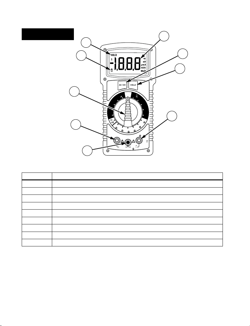
Number Description
1 COM Input - common or low input for all measurements
2 Amp Input
3 Function/Range Selector Switch
4 Low Battery Indicator
5 Hold Indicator
6 3 ½ Digit LCD with unit indicators
7 AC/DC Button
8 Hold Button
9 High input - voltage and resistance
Page 7

HD110C Heavy-Duty Digital Multimeter
Contents
Symbols ........................................................................................................................................................2
Introduction .................................................................................................................................................2
Warnings and Precautions .......................................................................................................................... 2
Instrument Familiarization ......................................................................................................................... 3
Overload Indication ....................................................................................................................................3
Measuring Procedures ................................................................................................................................3
DC & AC Voltage Measurement (See Figure 1) ......................................................................................... 4
DC and AC Current Measurement (See Figure 2) ...................................................................................... 4
Resistance Measurement (See Figure 3) ....................................................................................................4
Diode and Continuity Test (See Figure 4) ..................................................................................................4
AC/DC Button ..............................................................................................................................................5
Hold Button .................................................................................................................................................5
Auto-Power Down ......................................................................................................................................5
Incorrect Input Warning ............................................................................................................................. 5
Safety Test Leads .........................................................................................................................................5
Optional Accessories ................................................................................................................................... 5
Specifications ............................................................................................................................................... 6
Maintenance & Repair ................................................................................................................................ 8
Battery / Fuse Replacement (See Figure 5) ................................................................................................8
Repair ........................................................................................................................................................... 9
1
Page 8

Symbols
B
Battery
Double insulated
Direct Current
Alternating Current
Fuse
Conforms to relevant
Australian standards.
Do not dispose of this product as unsorted municipal waste. Contact Amprobe or a
qualified recycler for disposal.
Refer to the manual
Dangerous Voltage
Earth Ground
Audible tone
Complies with EU directives
Canadian Standards Association.
®
[Note: Canadian and US.]
Introduction
The HD110C Heavy-Duty Digital Multimeter is a 3-1/2 digit, manual ranging, ac-coupled average
measuring rms reading display instrument that measures: voltage, current, resistance, continuity, and
diode junctions. Menu selection allows Data Hold and ac or dc voltage and current selection.
Warnings and Precautions
This instrument is EN61010-1 certified for Cat IV, 1000 V ac/1500 V dc and lower installations.
Based on EN61010-1 transient requirements, this product should only be used in installations
where transients do not exceed 12,000 volts (a 1.2 µS/50 µS pulse).
• All inputs are protected against continuous overload conditions up to the limits of
each function's stated input protection (see specifications). Never exceed these limits or the
ratings marked on the instrument itself.
• Exercise extreme caution when: measuring voltag e >20 V, current >10 mA, ac power
line with inductive loads, ac power line during electrical storms. High voltages can be lethal
and high voltage transients may occur at any time.
• Operator injury or damage to the multimeter may occur during current measurements
if the fuse blows in a circuit with open circuit voltage exceeding 1000 V ac/1500 V dc.
• Always inspect your DMM, test leads and accessories for signs of damage or
abnormality before use. If an abnormal condition exists (broken or damaged test leads,
cracked case, display not reading, etc.), do not use. The internal fuse cover is integral to the
EN61010-1 Cat IV safety rating and must be in place to avoid potential shock hazards
• When testing for voltage or current, make sure these ranges function correctly. Take a
reading of a known voltage or current first.
• Never ground yourself when taking measurements. Do not touch exposed metal pipes,
outlets, fixtures, etc., which might be at ground potential. Keep your body isolated from
ground and never touch exposed wiring, connections, test probe tips, or any live circuit
conductors. Do not use the Flex-Strap to attach the meter to your body.
• Always measure current in series with the load – NEVER connect the multimeter
2
Page 9

ACROSS a voltage source. Check fuse first.
• Never replace a fuse with one of a different rating.
• Do not operate instrument in an explosive atmosphere (flammable gases, fumes,
vapor, dust.)
• Do not use this or any piece of test equipment without proper training
• CRT SERVICE SAFETY REMINDER: A potential danger exists when measuring voltages in
the horizontal output and damper stages of CRT equipment. (High voltage transients greater
than 8000 V). Refer to your CRT service manual for proper servicing instructions.
Instrument Familiarization
Your shipping carton should include the multimeter, a holster with Magne-Grip hanging strap, one test
lead set (one black, one red) threaded alligator clips, one 9 V battery (installed), one 2 mm hex wrench
(inside holster) and this manual. If any of the items are damaged or missing, immediately return the
complete package to the place of purchase for an exchange.
Protective Holster
The holster/tilt stand protects the meter form accidental falls and provides greater ease of use. Both test
lead probes can be attached to the holster for storage. One probe can be attached for measurement,
holding the meter with probe in one hand and the second probe in the other hand.
Overload Indication
Overload Indication: (input exceeds meter’s highest range) and Display Overload (input
exceeds selected range) are both signaled by a 1 displayed on the left side of the LCD.
higher range to display the input reading. If the highest range is selected and the overload indication
continues, this is now an Input Overload. Remove the test leads from the circuit immediately as input
exceeds the meter’s rated capability.
Note: In both instances, the overload indication is normal in the OHMS and Continuity/Diode ranges to
indicate an open circuit. Function Error is signaled a by continuous tone when a test lead is placed in
either the 2 A jack and the selector switch is not in the correct current range. If the meter is connected
to a voltage source with test leads set for current, very high current could result. All current ranges are
protected with fast acting fuses.
Battery Low: When the battery low indicator is displayed the battery has less than 50 hours operation
and the accuracy of the meter can no longer be guaranteed.
In the volts or amperage ranges Display Overload can be corrected by selecting a
Measuring Procedures
Turn the meter on by turning the function/range switch away from OFF and selecting the parameter
you want to measure. If the parameter selected has more than one range position, the display will
indicate the range by a changing position of the decimal point. Always select the highest range if the
maximum potential reading is not known. Then turn the selector switch down in range to obtain the
best resolution reading.
1. When connecting or disconnecting test leads to a circuit, always turn off power to device or
circuit being tested and discharge all capacitors.
2. Strictly observe the max input limits.
3. Do not change functions while test leads are connected to circuit.
3
Page 10

DC & AC Voltage Measurement (See Figure 1)
1. Connect test leads to the meter as shown in Figure 1.
2. Turn function selector switch to V and the desired range.
3. Press the AC/DC menu button to display either ac or dc indicator.
4. Touch Probe tips across voltage source (in parallel with circuit).
5. Voltage value will appear on Digital Display along with the voltage polarity (for dc).
DC and AC Current Measurement (See Figure 2)
1. Connect red test lead to the A input for current measurements up to 2 A. Connect black test
lead to COM input connector.
2. Set the Function Switch to the desired current range.
3. Press the AC/DC menu button to display either AC or DC indicator.
4. Open circuit in which current is to be measured (voltage between this point and ground must
not exceed 1000 V ac/1500 V dc). Securely connect test leads in series with the load.
5. Turn on power to circuit being tested.
6. Read current value on Digital Display.
Incorrect Input Warning: A tone will sound when a test lead is connected to the amperage jack, but the
selector switch is not set to the correct current range. Ranges 200 µA to 2 A require the test lead to be in
the A jack.
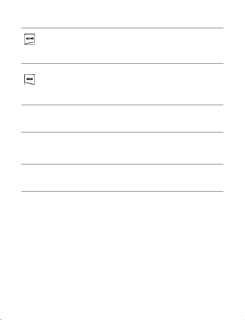
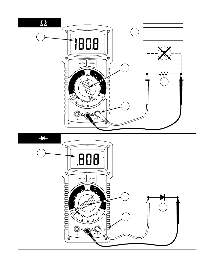
Resistance Measurement (See Figure 3)
1. Turn off any power to the resistance to be measured and discharge any capacitors. Any
voltage present during a resistance measurement will cause inaccurate readings.
2. Connect test leads to the meter as shown in Figure 3.
3. Set Function/Range Switch to the desired resistance range.
4. Connect test leads to circuit being measured.
5. Read resistance value on digital display. Open circuits will be displayed as “1”.
Diode and Continuity Test (See Figure 4)
The diode test measures the voltage drop across a diode junction.
1. Connect the test leads as shown in Figure 4.
2. Set the Function/range switch to
3. Apply probe tip of red lead to the anode and the black lead to the cathode of the diode.
4. The meter’s display indicates the forward voltage drop (approx. 0.6 V for silicon diode or
0.4 V for germanium diode). An open diode is indicated by “1”.
5. Reverse test lead connections to the diode to perform a reverse bias test. “1” indicates a
Notes: “1” for both reverse and forward bias tests indicates an open diode. A low voltage reading for
both bias tests indicates a shorted diode. If the diode is shunted by a resistor of 1000 Ω or less, it must be
removed from the circuit before taking the measurement. Bipolar transistor junctions may be tested in
the same manner described above as emitter-base and base-collector junctions are diode junctions.
When measuring continuity (also for shorted diodes) the meter emits a continuous tone when the
resistance value falls below 50 .
good diode.
.
4
Page 11
AC/DC Button
The AC/DC button works in conjunction with the Selector Switch to alternate the type of
input desired for the Volts and Amperes ranges. Each press of the button will alternate
the input type again and an ac or dc indication will be appear on the display.
Hold Button
Data Hold freezes the reading present on the LCD at the moment the button is pressed.
To use this menu feature set up the meter for the type of measurement and range
desired. Connect the test leads to the circuit/component to be measured, then press Hold.
The LCD reading will freeze and display “HOLD.” You may now remove the test leads and
the reading will not change until you press Hold again.
Auto-Power Down
In order to save battery life, your multimeter powers down automatically after approximately 30
minutes of inactivity. You can turn it back on by turning the function selector switch to OFF and back to
a measuring function.
Incorrect Input Warning
The meter sounds a steady audio tone and displays when a test lead is placed in the 2 A input jack
and the Selector switch is not set to a correct current position. If the multimeter is connected to a
voltage source with leads set for current, very high current could result. All current ranges are protected
with fast acting fuses.
Safety Test Leads
The test leads included with your meter have shrouded banana plugs to eliminate the possibility of
shock if the plugs accidentally pull out of the meter while making a measurement. Replacement part
number for safety test leads is TL1500.
Optional Accessories
CT235A 1000 A ac/dc Clamp FP700 2 A/1500 V Fuse
CT237A 200 A ac/dc Current Clamp
CT238A 20 A ac/dc Current Clamp TC253B
DC205C Deluxe Hard-Shell Carring Case TL1500
DC207C
Large Deluxe Hard-Shell Carry
Case with extra space for
accessories
HV23110A
VC221B Padded Vinyl Carrying Case
High Voltage Probe
Temperature Converter
(900 °C/1652 °F)
Standard Replacement Test Leads
with threaded alligator clips,
CAT IV
5
Page 12

Specifications
General Specifications
Display: 3-1/2 digit LCD, 1999 counts, with
annunciators and menu features
Polarity Indication: Automatic
Input overload indication: 1
Low Battery Indication: B < 50 hours battery life
remain, accuracy is no longer guaranteed
Display Update Rate: 2.5/sec, nominal
Oper. Temp. (< 75 % R.H.): 0 °C to +50 °C
Storage Temp: -20 °C to 60 °C, 0 to 80 % RH,
battery removed
Temperature coefficient: 0.1 x spec. accuracy /°C
(0–18 °C and 28–50 °C) all functions and ranges
except for mVDC
Temperature coefficient: 0.3 x spec. accuracy /°C
(0–18 °C and 28–50 °C) for mVDC
Environment: Indoor use only.
Altitude: Up to 2000 m
Power: Standard 9 V battery, NEDA 1604, JIS
006P,IEC 6F22
Auto Power-Down: Meter powers down after
approx. 30 min. of inactivity.
Battery Life: 250 hours typical with carbon-zinc,
500 hours typical with alkaline
Dimensions, with holster (H x W x D): 200 x 102 x
59 mm (7.9 in x 4.0 in x 2.3 in)
Weight (incl. battery): 642 g (1.4 lb)
Accessories: Test leads, battery (in instrument),
hex wrench in holster, Magne-Grip flex strap and
Users Manual
Case material: Flame retardant, high-impact
thermoplastic
Safety: meets EN 61010-1 Cat IV - 1500 V dc and
1000 V ac rms, Class II EN60529:IP67
EMC: Meets EN 61326-1
This product complies with requirements of
the following European Community Directives:
89/336/EEC (Electromagnetic Compatibility) and
73/23/EEC (Low Voltage) as amended by 93/68/EEC
(CE Marking).
However, electrical noise or intense
electromagnetic fields in the vicinity of the
equipment may disturb the measurement circuit.
Measuring instruments will also respond to
unwanted signals that may be present within
the measurement circuit. Users should exercise
care and take appropriate precautions to avoid
misleading results when making measurements in
the presence of electronic interference.
Electrical Specifications
Accuracies at 23 °C ± 5 °C, <75 % RH noncondensing, guaranteed for one year.
DC Volts
Ranges: 200 mV, 2 V, 20 V, 200 V, 1500 V
Resolution: 0.1 mV
Accuracy: All ranges ±(0.1 % rdg+2 dgts)
Input Impedance: 10 MΩ
OL Protection: 1500 V dc/1000 V ac rms
Transient Protection: 12 kV impulse (1.2 µS/50 µS)
based on EN 61010-1:2001 impulse requirement
for at CAT IV 1000 V product. This product should
not be used in installations where transients
exceed 12 kV.
AC Volts (45 Hz to 2 kHz)
Ranges: 200 mV, 2 V, 20 V, 200 V, 1000 V
Resolution: 0.1 mV
Accuracy:
200 mV to 200 V (45-500 Hz): ±(0.8 % rdg+4 dgts)
1000 V (50-60 Hz): ±(0.8 % rdg+4 dgts),
200 mV to 200 V (500 Hz-2 kHz): ±(1. 5% rdg+5
dgts),
1000 V (60-500 Hz): ±(1.5 % rdg+5 dgts)
Input Impedance: 10 MΩ
6
Page 13

OL Protection: 1500 V dc/1000 V ac rms
Transient Protection: 12 kV impulse (1.2 µS/50 µS)
based on EN 61010-1:2001 impulse requirement
for at CAT IV 1000 V product. This product should
not be used in installations where transients
exceed 12 kV.
DC Current
Ranges: 200 µA, 2 mA, 20 mA, 200 mA, 2 A
Resolution: 0.1 µA
Accuracy: 200 µA to 20 mA: ±(0.5 % rdg+2 dgts),
200 mA to 2 A: ±(1.0 % rdg+2 dgts)
Voltage Burden: 250 mV max.
(1 mV/1 µA on 200 µA Range),
(100 mV/1 mA on 2 mA Range),
(10 mV/1 mA on 20 mA Range),
(1.5 mV/1 mA on 200 mA Range),
(500 mV/1 A on 2 A Range)
OL Protection: A Input (F 2 A/1500 V,
size 8 x 65 mm IR fast blow ceramic)
AC Current (45 Hz to 1 kHz)
Ranges: 200 µA, 2 mA, 20 mA, 200 mA, 2 A
Resolution: 0.1 µA
Accuracy: 200 µA to 20 mA: ±(0.8 % rdg+4 dgts),
200 mA to 2 A: ±(1.2 % rdg+4 dgts)
Voltage Burden: 250 mV max. (1 V on 2 A range)
OL Protection: Same as DC Current.
Resistance
Ranges: 200 Ω, 2 kΩ, 20 kΩ, 200 kΩ, 2 MΩ, 20 MΩ
Resolution: 0.1 Ω
Accuracy: 200 Ω ±(0.5 % rdg+4 dgts),
2 kΩ to 200 kΩ: ±(0.3 %rdg+2 dgts),
2 MΩ: ±(1.0 % rdg+4 dgts),
20 MΩ: ±(2.0 %rdg+4 dgts)
OL Protection: 1500 V dc/1000 V ac rms
Open Circuit Voltage, 200 Ω rng: 3.0 V dc typical;
all other rngs 0.3 V dc typical.
Diode/Continuity Test
Test Current: 1m A dc typical
Test/Open Circuit Voltage: 3.0 V dc Typical
Diode Accuracy: ±(1.5 % rdg +2 dgts)
Continuity Audible Threshold: < 50 Ω ± 25 Ω
Response Time: <100 msec
OL Protection: 1500 V dc/1000 V ac rms
7
Page 14

Maintenance & Repair
If there appears to be a malfunction during the operation of the meter, the following steps should be
performed in order to isolate the cause of the problem:
1. Check the battery.
2. Review the operating instructions for possible mistakes in operating procedure.
3. Inspect and test the test probes for a broken or intermittent connection.
4. Inspect and test the fuse. See Fuse Replacement.
Except for the replacement of the battery or fuse, repair of the multimeter should be performed only by
a Factory Authorized Service Center or by other qualified instrument service personnel. The front panel
and case can be cleaned with a mild solution of detergent and water. Apply sparingly with a soft cloth
and allow to dry completely before using. Do not use aromatic hydrocarbons or chlorinated solvents for
cleaning.
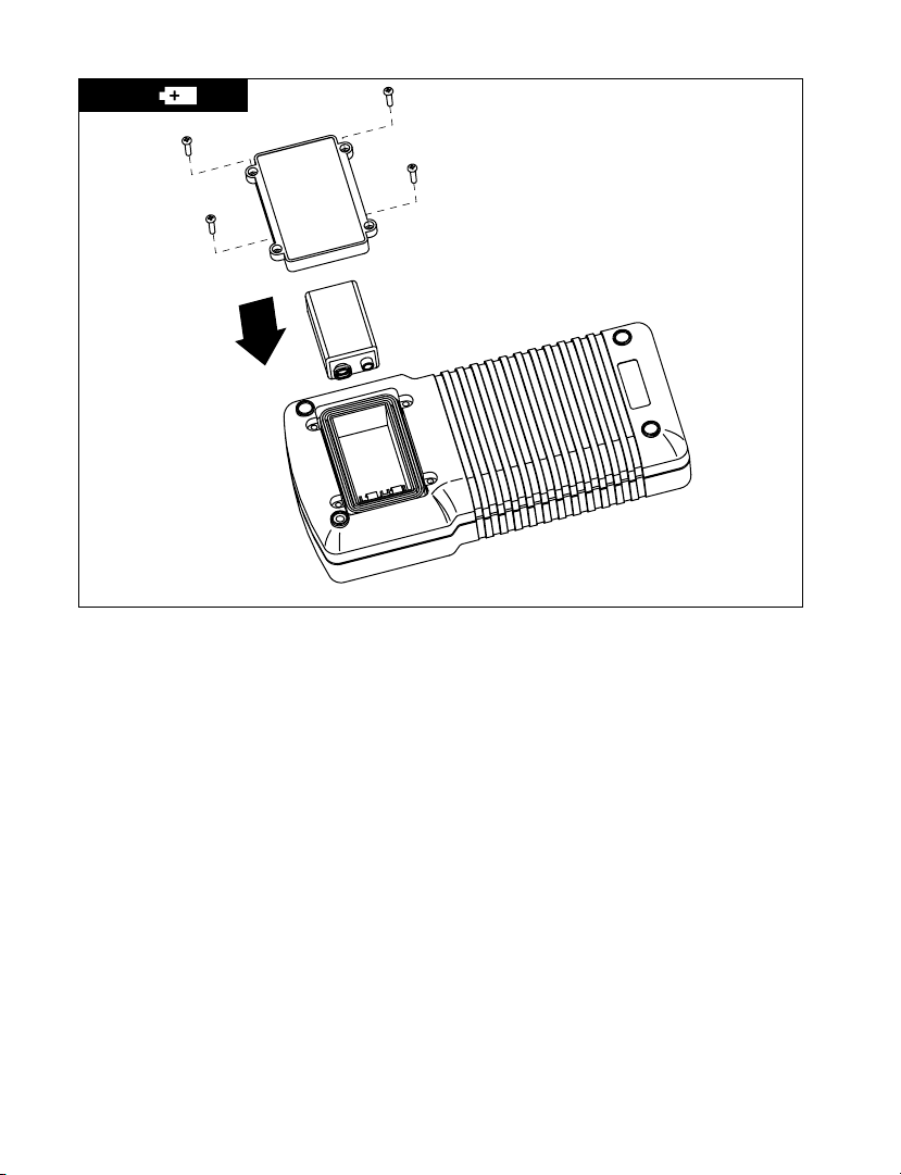
Battery / Fuse Replacement (See Figure 5)
Warning
To prevent electrical shock or meter damage, disconnect the meter’s test leads from any circuit and the
meter then turn the meter off before removing the rear case cover.
Precautions
• The hex head case screws each have a washer and gasket integral to the meter’s water/dustproof integrity. Upon opening, be sure these are retained and replaced when closing.
• Prying the rear case cover off with a knife or screwdriver is not recommend as this may
damage the case rim flanging and/or gasket and destroy the water/dust-proof integrity.
• The fuse cover is integral to the EN61010-1 Cat IV safety rating and must be replaced to avoid
potential shock hazards.
• Battery or fuse replacement should be performed in a clean environment and with
appropriate care taken to avoid contaminating the meter’s interior components.
• There are no user serviceable parts or components on the circuit boards. Disassembly beyond
the instructions listed below for battery and/or fuse replacement will void all warranties.
OPENING: Disconnect the test leads, turn off the meter and remove the holster. Remove the six hex head
screws in the face plate using the 2 mm hex wrench mounted in holster. Remove the rear case cover
carefully and place the front of the meter face down on a clean padded surface.
BATTERY REPLACEMENT: Disconnect the test leads, turn off the meter and remove the holster. Remove
the 4 hex head battery cover screws from the rear case cover using the 2 mm hex wrench as Shown in
Figure 5. Replace the battery with a NEDA type1604 or equivalent 9 V alkaline battery. Make sure the
battery compartment seal is in good condition and properly aligned before replacing the cover and
screws.
FUSE REPLACEMENT: Open the case by disconnecting the test leads, turn off the meter and remove the
holster. Remove the six hex head screws in the face plate using the 2 mm hex wrench mounted in the
holster. Remove the rear case cover carefully and place the front of the meter face down on a clean
padded surface. The fuses are located under a protective cover. Lift off cover and carefully remove the
fuse by gently prying under the fuse. Pry out the large fuse by placing a small flat screwdriver under
the fuse’s end caps. Do NOT use the gasket as a fulcrum point as this could permanently disfigure the
gasket.
Warning
Use only the same size and type fuse specified. Use of higher amperage or lower voltage or different
type fuses could result in shock, injury and/or damage to the meter. Replacement fuse is:
2 A/1500 V fast blow ceramic size 8 x 65 mm (small) fuse. Amprobe p/n: FP700.
CLOSURE: Replace the fuse cover and replace rear case cover careful not to bend or pinch the case rim
gasket. Reinstall the six hex-head screws with a gasket and washer and tighten securely with an even
amount of torque on each. Do NOT over tighten as this may strip case threading. Turn on the meter and
test operation. If working normally replace the holster.
8
Page 15

Repair
All test tools returned for warranty or non-warranty repair or for calibration should be
accompanied by the following: your name, company’s name, address, telephone number,
and proof of purchase. Additionally, please include a brief description of the problem or
the service requested and include the test leads with the meter. Non-warranty repair or
replacement charges should be remitted in the form of a check, a money order, credit card
with expiration date, or a purchase order made payable to Amprobe® Test Tools.
In-Warranty Repairs and Replacement – All Countries
Please read the warranty statement and check your battery before requesting repair.
During the warranty period any defective test tool can be returned to your Amprobe® Test
Tools distributor for an exchange for the same or like product. Please check the “Where to
Buy” section on www.amprobe.com for a list of distributors near you. Additionally, in the
United States and Canada In-Warranty repair and replacement units can also be sent to a
Amprobe® Test Tools Service Center (see address below).
Non-Warranty Repairs and Replacement – US and Canada
Non-warranty repairs in the United States and Canada should be sent to a Amprobe® Test Tools
Service Center. Call Amprobe® Test Tools or inquire at your point of purchase for current repair and
replacement rates.
In USA In Canada
Amprobe Test Tools Amprobe Test Tools
Everett, WA 98203 Mississauga, ON L4Z 1X9
Tel: 877-AMPROBE (267-7623) Tel: 905-890-7600
Non-Warranty Repairs and Replacement – Europe
European non-warranty units can be replaced by your Amprobe® Test Tools distributor for a nominal
charge. Please check the “Where to Buy” section on www.amprobe.com for a list of distributors near
you.
European Correspondence Address*
Amprobe® Test Tools Europe
P.O. Box 1186
5602 BD Eindhoven
The Netherlands
*(Correspondence only – no repair or replacement available from this address. European
customers please contact your distributor.)
9
Page 16

1
2
V
V
A
A
HD110C
V
A
COM
2A MAX
FUSED
MAX
1500V
1000V
OFF
20
M
2
M
200
k
20
k
2
k
200
IV
CAT
1000 V
200
mA
2 A
20
mA
2
mA
1500
1000
200
V
20
V
2
V
V
200
mV
200
A
HD110C
V
A
COM
2A MAX
FUSED
MAX
1500V
1000V
OFF
20
M
2
M
200
k
20
k
2
k
200
IV
CAT
1000 V
200
mA
2 A
20
mA
2
mA
1500
1000
200
V
20
V
2
V
V
200
mV
200
A
> 20V
4
2
0
2
0
0
1
5
3
1
3
2
6
4A
4B
4C
5
2
10
Page 17
3
4
HD110C
V
A
COM
2A MAX
FUSED
MAX
1500V
1000V
OFF
20
M
2
M
200
k
20
k
2
k
200
IV
CAT
1000 V
200
mA
2 A
20
mA
2
mA
1500
1000
200
V
20
V
2
V
V
200
mV
200
A
HD110C
V
A
COM
2A MAX
FUSED
MAX
1500V
1000V
OFF
20
M
2
M
200
k
20
k
2
k
200
IV
CAT
1000 V
200
mA
2 A
20
mA
2
mA
1500
1000
200
V
20
V
2
V
V
200
mV
200
A
2
0
0
2
2
3
4
1
2
4
1
3
5
Discharge capacitors
Décharger les condensateurs
Scaricare i condensator
Kondensatoren entladen
Descargue los condensadores
Ladda ur kondensatorer
11
Page 18
5
12
Page 19

HD110C
Heavy-Duty
Digital Multimeter
Mode d’emploi
Francais
Page 20
Fonctions du HD110C
HD110C
HD110C
V
A
COM
2A MAX
FUSED
MAX
1500V
1000V
OFF
20
M
2
M
200
k
20
k
2
k
200
IV
CAT
1000 V
200
mA
2 A
20
mA
2
mA
1500
1000
200
V
20
V
2
V
V
200
mV
200
A
2
2
0
2
0
0
1
2
3
5
4
6
7
8
9
Numéro Description
1 Entrée COM – entrée faible ou commune de toutes les mesures
2 Entrée des ampères
3 Sélecteur de gamme/fonction
4 Indicateur de pile faible
5 Indicateur de maintien d’affichage
6 Ecran LCD à 3,5 chiffres avec indication des unités
7 Touche c.a./c.c.
8 Touche de maintien d’affichage
9 Entrée élevée – tension et résistance
Page 21

HD110C Heavy-Duty Digital Multimeter
Table des matières
Symboles ...................................................................................................................................................2
Introduction ..............................................................................................................................................2
Mises en garde et précautions ................................................................................................................2
Apprentissage de l’instrument ................................................................................................................3
Indication de surcharge ...........................................................................................................................3
Techniques de mesure ..............................................................................................................................3
Mesure de tension continue et alternative (voir Figure 1) ....................................................................4
Mesure de tension continue et alternative (voir Figure 2) ....................................................................4
Mesure de résistance (voir Figure 3) .......................................................................................................4
Contrôle de diode et de continuité (voir Figure 4) ................................................................................4
Touche AC/DC ...........................................................................................................................................5
Touche Hold ..............................................................................................................................................5
Mise en veille automatique .....................................................................................................................5
Signalement des entrées incorrectes ......................................................................................................5
Cordons de test de sécurité .....................................................................................................................5
Accessoires en option ...............................................................................................................................5
Spécifications ............................................................................................................................................6
Entretien et réparations ..........................................................................................................................8
Changement de la pile / des fusibles (voir Figure 5) ..............................................................................8
Réparation ................................................................................................................................................9
1
Page 22
Symboles
B
Batterie
Double isolation
Courant continu
Courant alternatif
Fusible
Conforme aux normes
australiennes pertinentes.
Ne pas mettre ce produit au rebut avec les déchets ménagers. Contacter Amprobe
ou un centre de recyclage qualifié pour sa mise au rebut.
Se reporter au mode d’emploi
Tension dangereuse
Prise de terre
Signal sonore
Conforme aux directives de l’UE
Association canadienne de
®
normalisation
[Remarque : Canada et Etats-Unis.]
Introduction
Le multimètre numérique à grand rendement HD110C est un instrument affichant des mesures efficaces
moyennes couplées en courant alternatif, à mode de gamme manuel, 3,5 chiffres de résolution. Il mesure : la
tension, le courant, la résistance, la continuité et les jonctions à diode. Les sélections de menu permettent de
geler les données sur l’affichage et de choisir le courant et la tension alternatifs ou continus.
Mises en garde et précautions
Cet instrument est certifié EN61010-1 pour les installations Cat IV, 1000 V c.a./1500 V c.c. et
inférieures. Conformément aux caractéristiques de transitoires EN61010-1, cet appareil ne
doit être utilisé que si les transitoires dans les installations ne dépassent pas 12000 volts
(une impulsion de 1,2 µS/50 µS).
• Toutes les entrées sont protégées contre les conditions de surcharge continues jusqu’aux
seuils de protection d’entrée déclarés de chaque fonction (voir Spécifications). Ne jamais
dépasser ces limites ou les valeurs nominales indiquées sur l’instrument proprement dit.
• Faire preuve d’extrême prudence en : mesurant les tensions > 20 V, les courants
> 10 mA, les lignes d’alimentation secteur à charges inductives, les lignes d’alimentation
secteur pendant les orages électriques. Les tensions élevées peuvent être mortelles et des
transitoires à tension élevée peuvent se produire à tout moment.
• L’opérateur risque d’être blessé et le multimètre d’être endommagé pendant les
mesures de courant si le fusible saute dans un circuit avec une tension en circuit ouvert
supérieure à 1000 V c.a./1500 V c.c.
• Toujours inspecter le multimètre numérique, les cordons de mesure et les accessoires
pour détecter tout dommage ou anomalie avant l’emploi. Ne pas utiliser l’instrument en
présence d’une condition anormale (cordons de mesure endommagés ou brisés, boîtier
fissuré, affichage sans mesure, etc.). Le capot interne de fusible fait partie intégrante de la
norme de sécurité EN61010-1 Cat IV ; il doit être en place pour éviter les chocs électriques
potentiels.
• S’assurer que ces gammes fonctionnent correctement en testant les tensions et les
courants. Relever d’abord une mesure de courant ou de tension connue.
• Ne jamais se relier à la terre en prenant des mesures. Ne pas toucher les tuyaux
métalliques exposés, les prises, les accessoires fixes, etc. qui peuvent avoir un potentiel
à la terre. Le corps de l’utilisateur doit être isolé de la terre et ne jamais toucher les fils
exposés, les branchements, les extrémités des sondes ni aucun conducteur de circuit sous
2
Page 23

tension. Ne pas utiliser la sangle flexible pour s’attacher l’appareil au corps.
• Toujours mesurer le courant en série avec la charge – ne JAMAIS connecter le multimètre
AUX BORNES d'une source de tension. Vérifier d’abord le fusible.
• Ne jamais installer un fusible de calibre différent.
• Ne pas utiliser l'appareil dans une atmosphère explosible (gaz inflammables, émanations,
vapeurs ou poussières).
• Ne pas utiliser cet appareil ni aucun autre module de test sans avoir reçu la
formation adéquate.
• RAPPEL DE SECURITE SUR LE SERVICE DES TUBES CATHODIQUES : La mesure de tensions
dans les systèmes d’amortisseurs et dans le balayage horizontal des équipements à
tubes cathodiques pose un danger potentiel. (Transitoires de tension élevée supérieurs à
8000 V.) Reportez-vous au manuel de service des tubes cathodiques pour les instructions
d’intervention appropriées.
Apprentissage de l’instrument
Votre carton d’emballage doit inclure le multimètre, un étui avec sangle de suspension Magne-Grip, un
jeu de cordons de mesure (un noir, un rouge) des pinces crocodiles filetées, une pile 9 V (installée), une
clé hexagonale de 2 mm (dans l’étui) et ce mode d’emploi. Si l’un de ces éléments est endommagé ou
manquant, renvoyez immédiatement le contenu complet de l’emballage au lieu d’achat pour l’échanger.
Etui de protection
La béquille et l’étui protègent l’appareil contre une chute accidentelle et facilitent son utilisation. Les
deux sondes de test se fixent à l’étui pour leur rangement. Une sonde peut être fixée pour les mesures,
l’opérateur tenant l’appareil avec la sonde d’une main et la deuxième sonde de l’autre.
Indication de surcharge
Indication de surcharge : (l’entrée dépasse la gamme supérieure du multimètre) et la surcharge affichée
(l’entrée dépasse la gamme sélectionnée) sont signalées par 1 à gauche de l’écran LCD. Dans la gamme
des ampères ou des volts, la surcharge affichée peut être corrigée en sélectionnant une gamme plus
élevée pour la mesure d’entrée. Si la gamme la plus élevée est déjà sélectionnée et que l’indication de
surcharge persiste, la charge est maintenant une surcharge d’entrée. Retirez les cordons de mesure du
circuit immédiatement car l’entrée dépasse la capacité nominale du multimètre.
Remarque : Dans les deux cas, l’indication de surcharge est normale dans les gammes OHMS et
Continuité/Diode pour indiquer un circuit ouvert. Une erreur de fonction est signalée par une tonalité
continue lorsqu’un cordon est positionné entre la prise 2 A et que le sélecteur n’est pas réglé sur la
gamme de courant correcte. Un courant très élevé risque de se produire si le multimètre est connecté à
une source de tension avec le jeu de cordons de mesure placé pour une lecture de courant). Toutes les
gammes de courant sont protégées par des fusibles instantanés.
Pile faible
inférieure à 50 heures et la précision du multimètre n’est plus garantie.
: Lorsque l’indicateur de pile faible est affiché, la pile assure une autonomie d’utilisation
Techniques de mesure
Mettez le multimètre sous tension en éloignant le sélecteur de fonction/gamme de la
position OFF pour choisir le paramètre à mesurer. Si le paramètre sélectionné a plusieurs
positions de gamme, l’affichage indique la gamme par un changement de position du
maximale n’est pas connue. Réglez ensuite le sélecteur sur une gamme inférieure pour obtenir une
mesure de résolution optimale.
point décimal. Sélectionnez toujours la gamme la plus élevée si la mesure potentielle
1. En branchant ou en débranchant les cordons de mesure à un circuit, mettez toujours
l’appareil ou le circuit testé hors tension et déchargez tous les condensateurs.
2. Respectez rigoureusement les limites d’entrée maximales.
3. Ne changez pas de fonctions alors que les cordons de mesure sont branchés au circuit.
3
Page 24

Mesure de tension continue et alternative (voir Figure 1)
1. Branchez les cordons de mesure au multimètre conformément à la figure 1.
2. Réglez le sélecteur de fonction sur V et sur la gamme souhaitée.
3. Appuyez sur la touche du menu AC/DC pour afficher l’indication c.a. ou c.c.
4. Appliquez les pointes de sonde aux bornes de la source de tension (en parallèle au circuit).
5. La tension mesurée apparaît sur l’affichage numérique, avec la polarité de tension (pour le
courant continu).
Mesure de tension continue et alternative (voir Figure 2)
1. Reliez le cordon de mesure rouge dans l’entrée A pour les mesures de courant jusqu’à 2 A.
Reliez le cordon de mesure noir au connecteur d’entrée COM.
2. Réglez le sélecteur de fonction sur la gamme de courant souhaitée.
3. Appuyez sur la touche du menu AC/DC pour afficher l’indication c.a. ou c.c.
4. Coupez le circuit sur lequel le courant doit être mesuré (la tension entre ce point et la terre
ne doit pas dépasser 1000 V c.a./1500 V c.c.). Branchez solidement les cordons de mesure en
série avec la charge.
5. Mettez le circuit à mesurer sous tension.
6. Relevez la mesure de courant sur l’affichage numérique.
Signalement des entrées incorrectes :
prise des ampères alors que le sélecteur n’est pas réglé sur la gamme de courant appropriée. La présence
du cordon de mesure dans la prise A est obligatoire pour les gammes de 200 µA à 2 A.
Une tonalité retentit lorsqu’un cordon de mesure est branché à la
Mesure de résistance (voir Figure 3)
1. Coupez l’alimentation à la résistance à mesurer et déchargez les condensateurs. La présence
d’une tension pendant une mesure de résistance entraîne des lectures erronées.
2. Branchez les cordons de mesure au multimètre conformément à la figure 3.
3. Réglez le sélecteur de fonction/gamme sur la gamme de résistance souhaitée.
4. Branchez les cordons de mesure au circuit mesuré.
5. Relevez la mesure de résistance sur l’affichage numérique. Les circuits ouverts sont indiqués
par « 1 ».
Contrôle de diode et de continuité (voir Figure 4)
Le contrôle de diode mesure la baisse de tension aux bornes d’une jonction à diode.
1. Branchez les cordons de mesure conformément à la figure 4.
2. Réglez le commutateur de fonction/gamme sur
3. Appliquez l’embout de la sonde du cordon rouge contre l’anode et le cordon noir contre la
cathode de la diode.
4. L’affichage du multimètre indique la baisse de tension dans le sens direct (approx. 0,6 V pour
une diode au silicium ou
0,4 V pour une diode au germanium). Une diode ouverte est indiquée par « 1 ».
5. Inversez les branchements des cordons de mesure à la diode pour exécuter un test de polarité
Remarques : Une diode ouverte lors des tests de polarité directe ou inversée est signalée par « 1 ». Une
lecture de basse tension pour les deux tests de polarité indique une diode en court-circuit. Si la diode
est shuntée par une résistance égale ou inférieure à 1000 Ω, elle doit être retirée du circuit avant la
mesure. Les jonctions des transistors bipolaires peuvent être testées de la façon décrite car les jonctions
émetteur-base et base-collecteur sont des jonctions à diode.
Quand le multimètre mesure la continuité (ou les diodes en court-circuit), il émet une tonalité continue
lorsque la résistance mesurée tombe en dessous de 50 .
inversée. « 1 » indique une diode en bon état.
.
4
Page 25

Touche AC/DC
AC
DC
La touche AC/DC fonctionne en association avec le sélecteur pour alterner le type
d’entrée souhaité en fonction des gammes des ampères et des volts. Chaque pression
de la touche permet de basculer de nouveau le type d’entrée et une indication c.a. ou
c.c. apparaît sur l’affichage.
Touche Hold
Le maintien de l’affichage gèle la mesure affichée sur l’écran LCD lorsque la touche est
activée. Pour utiliser cette fonction de menu, configurez le multimètre pour le type de
mesure et la gamme souhaités. Branchez les cordons de mesure au circuit/composant à
mesurer et appuyez sur Hold. La mesure affichée sur l’écran LCD est figée et « HOLD »
apparaît. Vous pouvez maintenant retirer les cordons ; la mesure reste affichée tant que
la touche Hold n’est pas réactivée.
Mise en veille automatique
Pour économiser la charge de la pile, le multimètre s’éteint automatiquement après une trentaine de
minutes d’inactivité. Vous pouvez le remettre en marche en éloignant le sélecteur de fonction de la
position OFF pour choisir une fonction de mesure.
Signalement des entrées incorrectes
Le multimètre émet une tonalité sonore fixe et affiche R lorsqu’un cordon de mesure est connecté au
jack d’entrée 2 A si le sélecteur n’est pas réglé sur une position de mesure de courant appropriée. Un
courant très élevé risque de se produire si le multimètre est connecté à une source de tension à l'aide
du jeu de cordons de mesure placés pour une lecture de courant. Toutes les gammes de courant sont
protégées par des fusibles instantanés.
Cordons de test de sécurité
Les cordons de mesure inclus au multimètre sont munis de fiches bananes gainées pour éliminer le
risque de choc électrique en cas de retrait accidentel des fiches du multimètre pendant la mesure. Le
numéro de référence des cordons de test de sécurité est TL1500.
Accessoires en option
CT235A Pince de courant 1000 A c.a./c.c. FP700 Fusible 2 A/1500 V
CT237A
CT238A
DC205C
DC207C
Pince ampèremétrique 200 A
c.a./c.c.
Pince ampèremétrique 20 A
c.a./c.c.
Mallette de transport rigide
de luxe
Grande mallette de transport
rigide de luxe avec rangements
d’accessoires supplémentaires
HV23110A
TC253B
TL1500
Sonde haute tension
Convertisseur de température
(900 °C/1 652 °F)
Cordons de rechange standard
avec pinces crocodiles filetées,
CAT IV
VC221B
Sacoche de transport
rembourrée en vinyle
5
Page 26

Spécifications
Caractéristiques générales
Affichage : Ecran LCD à 3,5 chiffres, 1999 comptes
avec fonctions de menus et indicateurs
Indication de polarité : Automatique
Indication de surcharge d’entrée : 1
Témoin de décharge de la pile :
de la pile est inférieure à < 50 heures, la précision
n’est plus garantie
Fréquence de rafraîchissement de l’affichage :
2,5/s, nominal
Température de fonctionnement (< 75 % H.R.) :
0 ° à +50 °C
Température d’entreposage : -20 °C à 60 °C, 0 à
80 % HR, pile désinstallée
Coefficient thermique : 0,1 x (précision spéc.)/°C
(0 ° à 18 °C et 28° à 50 °C) toutes les fonctions et
gammes excepté le mVDC
Coefficient thermique : 0,3 x (précision spéc.)/°C
(0 ° à 18 °C et 28° à 50 °C) pour le mVDC
Environnement : Uniquement à l’intérieur de
locaux.
Altitude : Jusqu’à 2000 m
Alimentation : Pile 9 V standard, NEDA 1604,
JIS 006P, CEI 6F22
Mise en veille automatique : Le multimètre
s’éteint après environ 30 mn d’inactivité.
Durée de vie : 250 heures typiques avec une pile
au carbone-zinc, 500 heures typique avec une pile
alcaline
Dimensions avec étui (H x l x L) : 200 x 102 x 59
mm (7,9 x 4,0 x 2,3 pouces)
Poids (avec pile) : 642 g (1,4 lb)
Accessoires : Cordons de mesure, pile (dans
l’instrument), clé hexagonale dans l’étui, sangle
flexible Magne-Grip et mode d’emploi
Matériau du boîtier : Thermoplastique à fort
impact, ignifuge
Sécurité : conforme à EN 61010-1 Cat IV – 1500 V
c.c. et 1000 V c.a. eff., classe II EN60529:IP67
CEM : Conforme à EN 61326-1
B Si l’autonomie
Ce produit est conforme aux exigences
des directives suivantes de la Communauté
européenne :
89/ 336/ CEE (Compatibilité électromagnétique) et
73/ 23/ CEE (Basse tension) modifiée par 93/ 68/
CEE (marquage CE).
Toutefois, le bruit électrique ou les champs
électromagnétiques intenses à proximité de
l’équipement sont susceptibles de perturber
le circuit de mesure. Les appareils de mesure
réagissent également aux signaux indésirables
parfois présents dans le circuit de mesure. Les
utilisateurs doivent faire preuve de prudence
et prendre les mesures nécessaires pour éviter
les erreurs de mesure en présence de parasites
électromagnétiques.
Caractéristiques électriques
Précisions à 23 °C ± 5 °C, < 75 % HR sans
condensation, garantie un an.
Volts c.c.
Gammes : 200 mV, 2 V, 20 V, 200 V, 1500 V
Résolution : 0,1 mV
Précision : Toutes gammes ± (0,1 % du résultat
+2 chiffres)
Impédance d’entrée : 10 M
Protection contre les surcharges (OL) : 1500 V c.c. /
1000 V c.a. eff.
Protection contre les transitoires : Impulsion de
12 kV (1,2 µS/50 µS) selon les caractéristiques
d’impulsion EN 61010-1:2001 pour les appareils
CAT IV 1000 V. Cet appareil ne doit pas être utilisé
si les transitoires dans les installations dépassent
12 kV.
Ω
6
Page 27

Volts c.a. (45 Hz à 2 Hz)
Gammes : 200 mV, 2 V, 20 V, 200 V, 1000 V
Résolution : 0,1 mV
Précision : 200 mV à 200 V (45 à 500 Hz) : ± (0,8 %
du résultat +4 chiffres) 1000 V (50 à 60 Hz) : ± (0,8
% du résultat +4 chiffres) ; 200 mV à 200 V (500
Hz à 2 kHz) : ± (1,5 % du résultat +5 chiffres)
1000 V (60 à 500 Hz) : ± (1,5 % du résultat +5
chiffres)
Impédance d’entrée : 10 M
Protection contre les surcharges (OL) : 1500 V c.c. /
1000 V c.a. eff.
Protection contre les transitoires : Impulsion de
12 kV (1,2 µS/50 µS) selon les caractéristiques
d’impulsion EN 61010-1:2001 pour les appareils
CAT IV 1000 V. Cet appareil ne doit pas être utilisé
dans les installations où les transitoires dépassent
12 kV.
Ω
Courant c.c.
Gammes : 200 µA, 2 mA, 20 mA, 200 mA, 2 A
Résolution : 0,1
Précision : 200
+2 chiffres), 200 mA à 2 A : ± (1,0 % du résultat
+2 chiffres)
Tension de charge : 250 mV max. (1 mV/1
la gamme 200 µA) (100 mV/1 mA sur la gamme 2
mA), (10 mV/1 mA sur la gamme 20 mA),
(1,5 mV/1 mA sur la gamme 200 mA),
(500 mV/1 A sur la gamme 2 A)
Protection contre les surcharges (OL) : Entrée A
(F 2 A/1500 V, fusible instantané à élément
céramique IR de 8 x 65 mm)
µA
µA à 20 mA : ± (0,5 % du résultat
µA sur
Courant c.a. (45 Hz à 1 kHz)
Gammes : 200
Résolution : 0,1
Précision : 200
+4 chiffres), 200 mA à 2 A : ± (1,2 % du résultat
+4 chiffres)
Tension de charge : 250 mV max. (1 V sur la
gamme 2 A)
Protection contre les surcharges (OL) : Identique
au courant c.c.
µA, 2 mA, 20 mA, 200 mA, 2 A
µA
µA à 20 mA : ± (0,8 % du résultat
Résistance
Gammes : 200 Ω, 2 kΩ, 20 kΩ, 200 kΩ, 2 MΩ, 20
MΩ
Résolution : 0,1
Précision, 200 Ω ± (0,5 % du résultat +4 chiffres),
2 kΩ à 200 kΩ ± (0,3 % du résultat +2 chiffres), 2
MΩ ± (1,0 % du résultat +4 chiffres), 20 MΩ ± (2,0
% du résultat +4 chiffres)
Protection contre les surcharges (OL) : 1500 V c.c. /
1000 V c.a. eff.
Tension de circuit ouvert, 200 Ω rng : 3,0 V c.c.
typique ; toutes les autres rngs 0,3 V c.c. typique.
Ω
Contrôle de diode/Continuité
Courant de test : 1m A c.c. typique
Tension de circuit ouvert/test : 3,0 V c.c. normal
Diode Précision : ± (1,5 % du résultat +2 chiffres)
Protection contre les surcharges (OL) : 1500 V c.c. /
1000 V c.a. eff.
Continuité Seuil sonore : < 50
Temps de réponse : < 100 ms
Ω ± 25 Ω
7
Page 28

Entretien et réparations
Si une anomalie est suspectée pendant le fonctionnement du multimètre, procédez
comme suit pour isoler la cause du problème :
1. Vérifiez la pile.
2. Consultez les consignes d’utilisation pour vérifier les erreurs possibles lors de l’utilisation.
3. Inspectez et testez les sondes de test pour détecter un branchement intermittent ou brisé.
4. Inspectez et testez le fusible. Reportez-vous à Changement des fusibles.
Les interventions sur le multimètre, à l’exception du changement de la pile ou des fusibles, doivent être
effectuées en usine dans un centre de service agréé ou par un autre personnel de réparation qualifié.
La face avant et le boîtier peuvent être nettoyés à l’aide d’une solution légère à base d’eau et de
détergent. Appliquez cette solution avec modération en utilisant un tissu doux et laissez bien sécher
avant l’utilisation. N’utilisez pas de solvants à base de chlore ou d’hydrocarbures aromatiques pour le
nettoyage.
Changement de la pile / des fusibles (voir Figure 5)
Avertissement
Pour éviter les chocs électriques ou l’endommagement du multimètre, débrancher les cordons de mesure
du circuit et du multimètre et mettre l’appareil hors tension avant de retirer la face dorsale du boîtier.
Précautions
• Chaque vis à tête hexagonale est munie d’une rondelle et d’un joint solidaires du multimètre
pour l’étanchéité à l’eau et aux poussières. Conservez ces éléments après l’ouverture du capot
et n'oubliez pas de les replacer à la fermeture.
• L’ouverture de la face dorsale du boîtier à l'aide d’un couteau ou d’un tournevis n’est pas
recommandée car cela risque d’endommager le joint et/ou le flasque sur le rebord du boîtier
et de détruire l’étanchéité aux liquides et aux poussières.
• Le capot de fusible fait partie intégrante de la norme de sécurité EN61010-1 Cat IV ; il doit
être remis en place pour éviter les chocs électriques potentiels.
• Les fusibles ou la pile doivent être remplacés dans un environnement propre et avec soin
pour ne pas contaminer les composants internes du multimètre.
• Les cartes à circuits imprimés ne contiennent aucune pièce ou composant réparables. Tout
démontage en dehors des instructions fournies ci-dessous sur le changement de la pile ou des
fusibles annule toutes les garanties.
OUVERTURE :
six vis à tête hexagonale de la plaque frontale en utilisant la clé hexagonale de 2 mm montée dans
l’étui. Retirez avec soin le capot arrière du boîtier et placez la face avant du multimètre sur une surface
matelassée et propre.
CHANGEMENT DE LA PILE :
Retirez les 4 vis de fixation à tête hexagonale du capot arrière en utilisant la clé hexagonale de 2 mm
conformément à la figure 5. Installez une pile alcaline de 9 V type NEDA 1604 ou équivalent. Vérifiez
l’étanchéité du logement de pile et son alignement avant de remettre les vis et le capot en place.
REMPLACEMENT DES FUSIBLES :
multimètre et retirez l’étui. Retirez les six vis à tête hexagonale de la plaque frontale en utilisant la
clé hexagonale de 2 mm montée dans l’étui. Retirez avec soin le capot arrière du boîtier et posez la
face avant du multimètre sur une surface matelassée et propre. Les fusibles sont situés sous un capot
de protection. Soulevez le capot et retirez soigneusement le fusible en le soulevant délicatement par
dessous. Extrayez le gros fusible en positionnant un petit tournevis plat sous les capuchons d’extrémité
du fusible. N’utilisez PAS le joint étanche comme point d’appui car cela risque de fausser définitivement
le joint.
Débranchez les cordons de mesure, éteignez le multimètre et retirez l’étui. Retirez les
Débranchez les cordons de mesure, éteignez le multimètre et retirez l’étui.
Ouvrez le boîtier en débranchant les cordons de mesure, éteignez le
8
Page 29

Utiliser uniquement un fusible de même type et de même calibre que celui spécifié. L’utilisation d’une
intensité supérieure ou d’une tension inférieure ou de différents types de fusibles peut provoquer des
chocs électriques, des blessures et/ou l’endommagement du multimètre. Le fusible de rechange est :
un (petit) fusible instantané en céramique de 2 A/1500 V et 8 x 65 mm. Réf. Amprobe : FP700.
Avertissement
FERMETURE :
ou coincer le joint sur le rebord du boîtier. Réinstallez les six vis à tête hexagonale avec un joint et une
rondelle et appliquez un couple de serrage uniforme sur chaque vis. Ne serrez PAS excessivement pour
ne pas fausser le filetage du boîtier. Mettez le multimètre sous tension et testez son fonctionnement. Si
l’appareil fonctionne correctement, remettez-le dans son étui.
Replacez soigneusement le capot de fusible et la face dorsale en veillant à ne pas plier
Réparation
Tous les appareils qui sont envoyés pour réparation ou calibrage dans le cadre de la
garantie ou en dehors de la garantie doivent être accompagnés de ce qui suit: Nom du
client, nom de la firme, adresse, numéro de téléphone et preuve d’achat. Prière de joindre
en outre à l’appareil de mesure une brève description du problème ou de la maintenance
désirée ainsi que les lignes de mesure. Les frais pour les réparations en dehors de la
garantie ou pour le remplacement d’instruments doivent être payés par chèque, virement
bancaire, carte de crédit (numéro de carte de crédit avec date d’expiration) ou une
commande doit être formulée au bénéfice de Amprobe Test Tools.
Réparations ou remplacement sous garantie – tous les pays.
Veuillez lire la déclaration de garantie subséquente et contrôler la pile avant de demander
des réparations. Pendant la période de garantie, tous les appareils défectueux peuvent
être renvoyés à un distributeur Amprobe Test Tools pour remplacement par un appareil
identique ou un produit similaire. Un répertoire des distributeurs agréés se trouve dans la
section « Where to Buy » (points de vente) sur le site web www.amprobe.com. De plus, aux
USA et au Canada, les appareils peuvent être envoyés à un centre de service après-vente
Amprobe Test Tools (adresse voir plus loin) pour réparation ou remplacement.
Réparations ou remplacement en dehors de la garantie - USA et Canada
Pour les réparations en dehors de la garantie aux Etats-Unis et au Canada, les appareils
sont envoyés à un centre de service après-vente Amprobe Test Tools. Vous pouvez obtenir
des renseignements sur les prix de réparation et de remplacement actuellement en vigueur
auprès de Amprobe Test Tools ou du point de vente.
Aux USA : Au Canada :
Amprobe Test Tools Amprobe Test Tools
Everett, WA 98203 Mississauga, ON L4Z 1X9
Tél.: 877-AMPROBE (267-7623) Tél.: 905-890-7600
Réparations ou remplacement en dehors de la garantie - Europe
Les appareils hors garantie peuvent être remplacés contre paiement par le distributeur
Amprobe Test Tools compétent. Un répertoire des distributeurs agréés se trouve dans la
section « Where to Buy » (points de vente) sur le site web www.amprobe.com.
Adresse de correspondance pour l’Europe*
Amprobe Test Tools Europe
P. O. Box 1186
5602 BD Eindhoven
Pays-Bas
*(Uniquement correspondance – pas de réparations, pas de remplacement à cette adresse.
Les clients en Europe s’adressent au distributeur compétent.)
9
Page 30

1
2
V
V
A
A
HD110C
V
A
COM
2A MAX
FUSED
MAX
1500V
1000V
OFF
20
M
2
M
200
k
20
k
2
k
200
IV
CAT
1000 V
200
mA
2 A
20
mA
2
mA
1500
1000
200
V
20
V
2
V
V
200
mV
200
A
HD110C
V
A
COM
2A MAX
FUSED
MAX
1500V
1000V
OFF
20
M
2
M
200
k
20
k
2
k
200
IV
CAT
1000 V
200
mA
2 A
20
mA
2
mA
1500
1000
200
V
20
V
2
V
V
200
mV
200
A
> 20V
4
2
0
2
0
0
1
5
3
1
3
2
6
4A
4B
4C
5
2
10
Page 31

3
4
HD110C
V
A
COM
2A MAX
FUSED
MAX
1500V
1000V
OFF
20
M
2
M
200
k
20
k
2
k
200
IV
CAT
1000 V
200
mA
2 A
20
mA
2
mA
1500
1000
200
V
20
V
2
V
V
200
mV
200
A
HD110C
V
A
COM
2A MAX
FUSED
MAX
1500V
1000V
OFF
20
M
2
M
200
k
20
k
2
k
200
IV
CAT
1000 V
200
mA
2 A
20
mA
2
mA
1500
1000
200
V
20
V
2
V
V
200
mV
200
A
2
0
0
2
2
3
4
1
2
4
1
3
5
Discharge capacitors
Décharger les condensateurs
Scaricare i condensator
Kondensatoren entladen
Descargue los condensadores
Ladda ur kondensatorer
11
Page 32

5
12
Page 33

HD110C
Heavy-Duty
Digital Multimeter
Bedienungshandbuch
Deutsch
Page 34

HD110C
HD110C
V
A
COM
2A MAX
FUSED
MAX
1500V
1000V
OFF
20
M
2
M
200
k
20
k
2
k
200
IV
CAT
1000 V
200
mA
2 A
20
mA
2
mA
1500
1000
200
V
20
V
2
V
V
200
mV
200
A
2
2
0
2
0
0
1
2
3
5
4
6
7
8
9
Nr. Beschreibung
HD110C Merkmale
1 COM-Eingang - gemeinsamer oder Tiefpegel-Eingang für alle Messungen
2 Ampere-Eingang
3 Funktions-/Bereichsauswahlschalter
4 Anzeige für schwache Batterie
5 Hold-Anzeiger
6 3 ½ Stellen LCD mit Einheitsanzeiger
7 AC/DC-Taste
8 Hold-Taste
9 Hochpegel-Eingang - Spannung und Widerstand
Page 35

HD110C Hochfestes Digitalmultimeter
Inhalt
Symbole ......................................................................................................................................................2
Einführung ..................................................................................................................................................2
Warnungen und Sicherheitshinweise ....................................................................................................... 2
Erste Schritte mit dem Messgerät .............................................................................................................3
Überlastanzeige .........................................................................................................................................3
Messverfahren ............................................................................................................................................3
Gleichspannungs- und Wechselspannungsmessung (siehe Abbildung 1) ..............................................4
Gleichstrom- und Wechselstrommessung (siehe Abbildung 2) ...............................................................4
Widerstandsmessung (siehe Abbildung 3) ...............................................................................................4
Diodentest und Durchgangsprüfung (siehe Abbildung 4) ......................................................................4
AC/DC-Taste ................................................................................................................................................5
Hold-Taste ...................................................................................................................................................5
Automatische Ausschaltung ......................................................................................................................5
Warnung „inkorrekter Eingang“ ..............................................................................................................5
Sicherheitsmessleitungen ..........................................................................................................................5
Optionales Zubehör ................................................................................................................................... 5
Spezifikationen ..........................................................................................................................................6
Wartung und Reparatur ............................................................................................................................ 8
Wechseln von Batterie und Sicherung (siehe Abbildung 5) ....................................................................8
Reparatur .................................................................................................................................................... 9
1
Page 36

Symbole
B
Batterie
Schutzisoliert
Gleichstrom (Direct
Current, DC)
Wechselstrom (Alternating
Current, AC)
Sicherung
Übereinstimmung mit den
relevanten australischen
Normen
Dieses Produkt nicht im unsortierten Kommunalabfall entsorgen. Für Entsorgung mit
Amprobe oder einer befähigten Recycling-Einrichtung Kontakt aufnehmen.
Im Handbuch nachlesen
Gefährliche Spannung
Erde, Masse
Akustischer Alarm
Übereinstimmung mit
EU-Vorschriften
Canadian Standards Association.
®
[Hinweis: Kanada und USA]
Einführung
Das HD110C Hochfeste Digitalmultimeter ist ein wechselstromgekoppeltes 3-1/2 Stellen EffektivwertMessgerät mit manueller Bereichswahl, das folgenden Größen misst: Spannung, Stromstärke,
Widerstand, Durchgang und Diodenübergänge. Die Menüauswahl ermöglicht Datenhaltemodus und
Wechsel- oder Gleichspannung sowie Stromstärke.
Warnungen und Sicherheitshinweise
Dieses Gerät ist zertifiziert gemäß EN61010-1 für Cat IV, 1000 V Wechselspannung/1500
V Gleichspannung und niedrigere Installationen. Dieses Produkt sollte gemäß EN61010-1
Störgrößenanforderungen ausschließlich in Installationen verwendet werden, in denen
Störgrößen 12.000 Volt (ein 1,2 µS/50 µS Impuls) nicht übersteigen.
• Alle Eingänge sind gegen fortdauernde Überlastbedingungen bis zu den Grenzwerten des
Nenneingangsschutzes der einzelnen Funktionen geschützt (siehe Spezifikationen). Diese
Grenzwerte bzw. die am Messgerät vermerkten Nennwerte niemals überschreiten.
• Äußerste Vorsicht walten lassen: beim Messen von Spannung > 20 V, Stromstärke
> 10 mA, Wechselspannungsleitungen mit Induktivlasten, Wechselspannungsleitungen
während Gewittern. Hochspannungen können lebensgefährlich sein und
Hochspannungsspitzen können jederzeit auftreten.
• Bedienerverletzung oder Beschädigung des Multimeters kann während Strommessungen
auftreten, wenn die Sicherung durchbrennt und Spannungen im offenen Stromkreis 1000
V Wechselspannung/1500 V Gleichspannung überschreiten.
• Das DMM, die Messleitungen und jegliches Zubehör vor Gebrauch stets auf Zeichen
von Beschädigung oder Abnormalität untersuchen. Wenn eine abnormale Bedingung
existiert (unterbrochene oder anderweitig beschädigte Messleitungen, geborstenes
Gehäuse, Anzeige zeigt nicht an usw.), das Gerät nicht verwenden. Die interne
Sicherungsabdeckung ist eine Komponente der EN61010-1 Cat IV Sicherheit und muss
vorhanden sein, um mögliche Stromschlaggefahr zu vermeiden.
• Beim Prüfen auf Spannung oder Stromstärke sicherstellen, dass diese Bereiche korrekt
funktionieren. Zuerst eine Messung einer bekannten Spannung oder Stromstärke
durchführen.
• Sich selbst isolieren, wenn Messungen durchgeführt werden. Keine exponierten
Metallrohre, Steckdosen, Vorrichtungen usw. berühren, die u. U. Erdungspotential
aufweisen. Den eigenen Körper erdfrei halten und niemals exponierte Drähte,
2
Page 37

Anschlüsse, Prüfspitzen/Messleitungen oder stromführende Stromkreisleiter berühren.
Das Messgerät nicht mit dem Flex-Strap am eigenen Körper anbringen.
• Strommessung immer in Serie mit der Last - das Multimeter NIEMALS über eine
Spannungsquelle anschließen. Zuerst die Sicherung prüfen.
• Niemals eine Sicherung durch eine Sicherung anderer Nennlast ersetzen.
• Das Gerät nicht in explosiver Umgebung betreiben (entzündliche Gase/Dämpfe/Dunst/Staub).
• Weder dieses Gerät noch andere Prüfausrüstung ohne angemessene Ausbildung
verwenden.
• HINWEIS ZUR SERVICESICHERHEIT BEI KATHODENSTRAHLRÖHREN: Eine potentielle
Gefahr existiert beim Messen von Spannungen in den Horizontalablenkungs- und
Schalterdioden-Stufen von Geräten mit Kathodenstrahlröhren. (Hochspannungsspitzen
größer als 8000 V.) Für geeignete Serviceanweisungen im Servicehandbuch zur
Kathodenstrahlröhre nachschlagen.
Erste Schritte mit dem Messgerät
Der Verpackungskarton sollte Folgendes enthalten: das Multimeter, ein Holster mit Magne-Grip-Aufhänger,
ein Messleitungssatz (1 schwarz, 1 rot), Gewinde-Krokodilklemmen, eine 9 V Batterie (installiert), ein 2 mm
Sechskantschlüssel (im Holster) sowie dieses Handbuch. Wenn einer dieser Artikel beschädigt ist oder fehlt,
unverzüglich die gesamte Sendung für einen Austausch an die Verkaufsstelle zurücksenden.
Schutzholster
Das Holster/der Neigefuß schützt das Messgerät gegen versehentlichen Fall und bietet höheren
Bedienkomfort. Beiden Prüfspitzen können zur Aufbewahrung am Holster angebracht werden. Für
Messungen kann eine Prüfspitze angebracht werden; das Messgerät mit Prüfspitze wird dann in einer
Hand gehalten und die zweite Prüfspitze in der anderen Hand.
Überlastanzeige
Überlastanzeige: (Eingang übersteigt den höchsten Bereich des Messgeräts) und
Anzeigeüberlast (Eingang übersteigt den ausgewählten Bereich) werden beide durch
Anzeigeüberlast durch Auswahl eines höheren Bereichs für die Anzeige der Eingangsmessung korrigiert
werden. Wenn der höchste Bereich ausgewählt wird und die Überlastanzeige fortdauert, handelt es sich
um eine Eingangsüberlast. Die Messleitungen unverzüglich von Stromkreis entfernen, wenn der Eingang
die Nennkapazität des Messgeräts übersteigt.
Hinweis: In beiden Fällen ist die Überlastanzeige zur Anzeige eines offenen Stromkreises in den OHM- und
Durchgangs-/Dioden-Bereichen normal. Funktionsfehler wird durch einen Dauerton signalisiert, wenn
eine Messleitung in die 2 A Buchse eingeführt wird oder der Auswahlschalter nicht auf den korrekten
Strombereich eingestellt ist. Wenn das Messgerät an eine Spannungsquelle angeschlossen wird und
die Messleitungen für Strommessung angelegt sind, können sehr hohe Stromstärken auftreten. Alle
Strombereiche sind mit flinken Sicherungen geschützt.
Schwache Batterie: Wenn die Anzeige für schwache Batterie angezeigt wird, reicht die Batterie für weniger
als 50 Stunden Betrieb aus und die Genauigkeit des Messgeräts kann nicht mehr gewährleistet werden.
eine 1 auf der linken Seite der LCD angezeigt. In den Volt- oder Ampere-Bereichen kann
Messverfahren
Das Messgerät durch Drehen des Funktions-/Bereichsschalters in eine andere Position als OFF einschalten
und den zu messenden Parameter auswählen. Wenn der ausgewählte Parameter mehr als eine
Bereichsposition hat, zeigt die Anzeige den Bereich durch eine wechselnde Position des Dezimalpunkts
an. Stets den höchsten Bereich auswählen, wenn der maximal mögliche Messwert unbekannt ist. Dann
den Auswahlschalter nach unten drehen, um die beste Messwertauflösung zu erzielen.
1. Beim Anschließen von Messleitungen an einen Stromkreis oder beim Trennen davon
stets die Stromversorgung zum zu prüfenden Gerät oder Stromkreis ausschalten und alle
Kondensatoren entladen.
2. Die maximalen Eingangsgrenzwerte genau beachten.
3. Die Funktion nicht wechseln, wenn Messleitungen an Stromkreisen angeschlossen sind.
3
Page 38

Gleichspannungs- und Wechselspannungsmessung (siehe
Abbildung 1)
1. Die Messleitungen gemäß Abbildung 1 an das Messgerät anschließen.
2. Den Funktionsauswahlschalter auf V und den gewünschten Bereich drehen.
3. Die AC/DC-Menütaste drücken, um entweder AC (Wechselspannung) oder
DC (Gleichspannung) einzublenden.
4. Die Prüfspitzen über der Spannungsquelle anlegen (parallel zu Stromkreis).
5. Der Spannungswert erscheint auf den Digitalanzeige zusammen mit der Spannungspolarität
(für Gleichspannung).
Gleichstrom- und Wechselstrommessung (siehe Abbildung 2)
1. Die rote Messleitung am A-Eingang für Stromstärkemessungen bis 2 A anschließen. Die
schwarze Messleitung am COM-Eingangsanschluss anschließen.
2. Den Funktionsschalter auf den gewünschten Strombereich einstellen.
3. Die AC/DC-Menütaste drücken, um entweder AC (Wechselspannung) oder
DC (Gleichspannung) einzublenden.
4. Den Stromkreis öffnen, dessen Stromstärke gemessen werden soll (Spannung zwischen
diesem Punkt und Erde darf 1000 V Wechselspannung/1500 V Gleichspannung nicht
übersteigen). Messleitungen gesichert in Serie mit der Last anschließen.
5. Die Stromversorgung zum zu prüfenden Schaltkreis einschalten.
6. Auf der Digitalanzeige den Stromstärkewert ablesen.
Warnung „inkorrekter Eingang“: Es wird ein Tonsignal ausgegeben, wenn eine Messleitung an eine
Ampere-Buchse angeschlossen ist und der Auswahlschalter nicht auf den korrekten Strombereich
eingestellt ist. Die Bereiche 200 µA bis 2 A erfordern, dass die Messleitung an die A-Buchse angelegt ist.
Widerstandsmessung (siehe Abbildung 3)
1. Jeglichen Strom zum zu messenden Widerstand ausschalten und alle Kondensatoren
entladen. Jegliche während einer Widerstandmessung vorhandene Spannung verursacht
ungenaue Messwerte.
2. Die Messleitungen gemäß Abbildung 3 an das Messgerät anschließen.
3. Den Funktions-/Bereichsschalter auf den gewünschten Widerstandsbereich einstellen.
4. Die Messleitungen an den zu messenden Stromkreis anschließen.
5. Auf der Digitalanzeige den Widerstandswert ablesen. Offene Stromkreise werden als „1“
angezeigt.
Diodentest und Durchgangsprüfung (siehe Abbildung 4)
Der Diodentest misst den Spannungsabfall über einen Diodenübergang.
1. Die Messleitungen gemäß Abbildung 4 anschließen.
2. Den Funktions-/Bereichsschalter auf
3. Die Prüfspitze der roten Messleitung an die Anode und die schwarze Messleitung an die
Kathode der Diode anlegen.
4. Die Anzeige des Messgeräts zeigt einen Vorwärtsspannungsabfall an (ungefähr 0,6 V für
Silikondioden bzw. 0,4 V für Germaniumdioden). Eine offene Diode wird als „1“ angezeigt.
5. Die Messleitungsverbindungen zur Diode umkehren, um einen Diodentest in Sperrrichtung
Hinweise: „1“ für beide Tests, in Sperrrichtung und Vorwärtsrichtung, zeigt eine offene Diode an.
Ein Niederspannungsmesswert für beide Tests zeigt eine kurzgeschlossene Diode an. Wenn die Diode
durch einen Widerstand von 1000
vom Stromkreis entfernt werden. Bipolartransistorübergänge können auf die gleiche Weise (wie oben
beschrieben) als Emitter-Basis- und Basis-Kollektor-Übergange getestet werden.
Beim Messen von Durchgang (auch für kurzgeschlossene Dioden) gibt das Messgerät einen Dauerton
aus, wenn der Widerstandswert unter 50 abfällt.
durchzuführen. „1“ zeigt eine gute Diode an.
Ω oder weniger parallelgeschaltet ist, muss sie vor der Messung
einstellen.
4
Page 39

AC/DC-Taste
Die Wechselstrom/Gleichstrom-Taste funktioniert in Verbindung mit dem
Auswahlschalter zum Umschalten des gewünschten Typs von Eingang für die Volt- und
Ampere-Bereiche. Jedes Drücken der Taste ändert den Typ von Eingang, und auf der
Anzeige wird AC oder DC angezeigt.
Hold-Taste
Der Datenhaltemodus friert den derzeit auf der LCD vorhandenen Messwert zum
Zeitpunkt des Tastendrucks ein. Um diese Menüfunktion zu verwenden, das Messgerät
für den gewünschten Typ von Messung und den gewünschten Bereich einrichten. Die
Messleitungen an den zu messenden Stromkreis bzw. Die zu messende Komponente
anschließen und dann die Taste HOLD drücken. Der LCD-Messwert wird eingefroren
und HOLD wird eingeblendet. Die Messleitungen können jetzt entfernt werden und der
Messwert verändert sich nicht, bis HOLD erneut gedrückt wird.
Automatische Ausschaltung
Um Batteriestrom zu sparen, schaltet sich das Multimeter nach ungefähr 30 Minuten Inaktivität
automatisch aus. Das Gerät kann durch Drehen des Funktionsauswahlschalters auf OFF und dann auf
eine Messfunktion wieder eingeschaltet werden.
Warnung „inkorrekter Eingang“
Das Messgerät gibt einen Dauerton aus und zeigt R an, wenn eine Messleitung in eine 2 A
Eingangsbuchse eingesteckt ist und der Auswahlschalter nicht in die korrekte Stromposition geschaltet
ist. Wenn das Multimeter an eine Spannungsquelle angeschlossen wird und die Messleitungen für
Strommessung angelegt sind, können sehr hohe Stromstärken auftreten. Alle Strombereiche sind mit
flinken Sicherungen geschützt.
Sicherheitsmessleitungen
Die mit dem Messgerät gelieferten Messleitungen verfügen über Sicherheitsbananenstecker zur
Vermeidung von Stromschlag, falls die Stecker während einer Messung versehentlich aus dem Messgerät
entfernt werden. Ersatzteilenummer für Sicherheitsmessleitungen: TL1500.
Optionales Zubehör
CT235A 1000 A AC/DC Klemme FP700 2 A/1500 V Sicherung
CT237A 200 A AC/DC Stromzange
CT238A 20 A AC/DC Stromzange TC253B
DC205C Deluxe Hartschalenkoffer TL1500
DC207C
Großer Deluxe Hartschalenkoffer
mit Platz für Zubehör
HV23110A
VC221B Gepolstertes Vinyletui
Hochspannungsprüfspitze
Temperaturwandler
(900 °C/1652 °F)
Standard-Ersatzmessleitungen
mit Gewinde-Krokodilklemmen,
CAT IV
5
Page 40

Spezifikationen
Allgemeine Spezifikationen
Anzeige: 3-1/2 Stellen LCD, 1999 Zählwerte, mit
Anzeigern und Menüfunktionen
Polaritätsanzeige: Automatisch
Eingangsüberlastanzeige: 1
Anzeige für schwache Batterie: B Anzeige < 50
Stunden Batteriebetrieb verbleiben, Genauigkeit
nicht länger gewährleistet
Anzeigeaktualisierungsrate: 2,5/s, nominal
Betriebstemp. (< 75 % RH): 0 °C bis +50 °C
Lagertemperatur: - 20 °C bis 60 °C, 0 bis 80 % RH,
Batterie entfernt
Temperaturkoeffizient: 0,1 x (spez. Genauigkeit)/
°C (0 ° bis 18 °C und 28° bis 50 °C) alle Funktionen
und Strecken außer mVDC
Temperaturkoeffizient: 0,3 x (spez. Genauigkeit)/
°C (0 ° bis 18 °C und 28° bis 50 °C) für mVDC
Umgebung: Gebrauch nur in Gebäuden.
Höhenlage: Bis 2000 m.
Stromversorgung: Standard-9-V-Batterie, NEDA
1604, JIS 006P, IEC 6F22
Automatische Ausschaltung: Messgerät schaltet
sich nach ungefähr 30 Minuten Inaktivität
automatisch aus.
Batterielebensdauer: 250 Stunden typisch mit
Kohlezink-Batterie, 500 Stunden typisch
mit Alkalibatterie
Abmessungen, mit Holster (H x B x L): 200 x 102
x 59 mm
Gewicht (inkl. Batterie): 642 g
Zubehör: Messleitungen, Batterie (im Messgerät),
Sechskantschlüssel im Holster, Magne-GripAufhänger und Bedienungshandbuch
Gehäusematerial: Flammenhemmendes,
hochfestes Thermoplast
Sicherheit: Erfüllt EN 61010-1 Cat IV - 1500 V DC
und 1000 V AC eff. Klasse II EN60529:IP67
EMV: Erfüllt EN 61326-1
Dieses Produkt erfüllt die Anforderungen
der folgenden EU-Richtlinien: 89/ 336/ EEC
(Elektromagnetische Verträglichkeit) und 73/ 23/
EEC (Niederspannung) mit dem Zusatz 93/ 68/ EEC
(CE-Kennzeichnung).
Doch elektrisches Rauschen oder intensive
elektromagnetische Felder in der Nähe des
Geräts können den Messschaltkreis stören.
Messgeräte reagieren auch auf unerwünschte
Impulse/Signale, die unter Umständen im
Messschaltkreis vorkommen. Die Benutzer
müssen die nötige Sorgfalt walten lassen und
geeignete Vorkehrungen treffen, um irreführende
Ergebnisse bei Messungen bei Vorhandensein
elektrischer Störeinflüsse zu vermeiden.
Elektrische Spezifikationen
Genauigkeit bei 23 °C ± 5 °C, < 75 % relative
Luftfeuchtigkeit, nicht kondensierend,
gewährleistet für 1 Jahr.
V Gleichspannung
Bereiche: 200 mV, 2 V, 20 V, 200 V, 1500 V
Auflösung: 0,1 mV
Genauigkeit: Alle Bereiche, ± (0,1 % MW +2
Stellen)
Eingangsimpedanz: 10 MΩ
Überlastschutz: 1500 V DC/1000 V AC eff.
Überspannungsschutz: 12 kV Impuls (1,2 µS/50 µS)
gemäß
EN 61010-1:2001 Impulsanforderung für CAT
IV 1000 V Produkt. Dieses Produkt sollte nicht
in Installationen verwendet werden, in denen
Überspannungen 12 kV übersteigen.
6
Page 41

AC Volt (45 Hz bis 2 kHz)
Bereiche: 200 mV, 2 V, 20 V, 200 V, 1000 V
Auflösung: 0,1 mV
Genauigkeit: 200 mV bis 200 V (45-500 Hz): ± (0,8
% MW +4 Stellen) 1000 V (50-60 Hz): ± (0,8 % MW
+4 Stellen); 200 mV bis 200 V (500 Hz-2 kHz): ± (1.
5 % MW +5 Stellen) 1000 V (60-500 Hz): ± (1,5 %
MW +5 Stellen)
Eingangsimpedanz: 10 MΩ
Überlastschutz: 1500 V DC/1000 V AC eff.
Überspannungsschutz: 12 kV Impuls (1,2 µS/50 µS)
gemäß
EN 61010-1:2001 Impulsanforderung für CAT
IV 1000 V Produkt. Dieses Produkt sollte nicht
in Installationen verwendet werden, in denen
Überspannungen 12 kV übersteigen.
Gleichstrom
Bereiche: 200 µA, 2 mA, 20 mA, 200 mA, 2 A
Auflösung: 0,1 µA
Genauigkeit: 200 µA bis 20 mA: ± (0,5 % MW +2
Stellen), 200 mA bis 2 A: ± (1,0 % MW +2 Stellen)
Spannungsbürde: 250 mV max.
(1 mV/1 µA auf 200 µA Bereich),
(100 mV/1 mA auf 2 mA Bereich),
(10 mV/1 mA auf 20 mA Bereich),
(1,5 mV/1 mA auf 200 mA Bereich),
(500 mV/1 A auf 2 A Bereich)
Überlastschutz: A Eingang (F 2 A/1500 V,
Grüße 8 x 65 mm IR flinke Keramiksicherung)
AC-Stromstärke (45 Hz bis 1 kHz)
Bereiche: 200 µA, 2 mA, 20 mA, 200 mA, 2 A
Auflösung: 0,1 µA
Genauigkeit: 200 µA bis 20 mA: ± (0,8 % MW
+4 Stellen), 200 mA bis 2 A: ± (1,2 % MW +4
Stellen)
Spannungsbürde: 250 mV max. (1 V auf 2 A
Bereich)
Überlastschutz: Gleich wie DC-Strom.
Widerstand
Bereiche: 200 Ω, 2 kΩ, 20 kΩ, 200 kΩ, 2 MΩ, 20
MΩ
Auflösung: 0,1 Ω
Genauigkeit, 200 Ω ± (0,5 % MW +4 Stellen),
2 kΩ bis 200 kΩ ± (0,3 % MW +2 Stellen), 2 MΩ
± (1,0 % MW +4 Stellen), 20 M
+4 Stellen)
Überlastschutz: 1500 V DC/1000 V AC eff.
Leerlaufspannung, 200 Ω Bereich: 3,0 V DC
typisch; alle übrigen Bereiche 0,3 V DC typisch.
Ω ± (2,0 % MW
Diodentest/Durchgangsprüfung
Test/Prüfstrom: 1 mA DC typisch
Test/Leerlaufspannung: 3,0 V DC typisch
Dioden Genauigkeit: ± (1,5 % MW +2 Stellen)
Überlastschutz: 1500 V DC/1000 V AC eff.
Durchgangsprüfung Akustische Schwelle: < 50
± 25 Ω
Ansprechzeit: < 100 ms
Ω
7
Page 42

Wartung und Reparatur
Wenn ein Fehlverhalten während des Betriebs des Messgeräts vermutet wird, sollten die folgenden
Schritte durchgeführt werden, um die Ursache des Problems genau zu bestimmen:
1. Die Batterien prüfen.
2. Die Bedienungsanleitungen studieren, um mögliche Fehler bei der Bedienung zu erkennen.
3. Die Prüfspitzen auf unterbrochene oder intermittierend aussetzende Verbindung
untersuchen und testen.
4. Die Sicherung untersuchen und testen. Siehe „Wechseln der Sicherung“.
Reparaturen am Multimeter müssen ausschließlich durch werkseitig autorisiertes Servicepersonal oder
Messgerät-Fachpersonal durchgeführt werden, davon ausgenommen sind lediglich das Wechseln von
Batterien und Sicherungen. Die Vorderseite und das Gehäuse können mit einer milden Lösung von
Reinigungsmittel und Wasser gereinigt werden. Die Lösung spärlich mit einem weichen Tuch anwenden
und das Gerät vor Gebrauch vollständig trocknen lassen. Keine aromatischen Kohlenwasserstoffe oder
Chlorlösungsmittel zur Reinigung verwenden.
Wechseln von Batterie und Sicherung (siehe Abbildung 5)
Warnung
Zur Vermeidung von Stromschlag bzw. Messgerätbeschädigung die Messleitungen des Messgeräts
von allen Stromkreisen und dem Messgerät trennen und dann vor Abnehmen der hinteren
Gehäuseabdeckung das Messgerät ausschalten.
Sicherheitshinweise
• Alle Sechskant-Gehäuseschrauben sind zur Gewährleistung der Staub-/Wasserbeständigkeit
des Messgeräts mit Scheiben und Dichtungen ausgestattet. Beim Öffnen darauf achten,
dass diese Scheiben und Dichtungen bewahrt bleiben und beim Schließen wieder
eingesetzt werden.
• Herausdrücken der hinteren Gehäuseabdeckung mit einem Messer oder Schraubendreher
wird nicht empfohlen, das dies den Gehäuserand und/oder die Dichtung beschädigen und die
Staub-/Wasserbeständigkeit des Messgeräts beeinträchtigen kann.
• Die Sicherungsabdeckung ist eine Komponente der EN61010-1 Cat IV Sicherheit und muss
wieder angebracht werden, um mögliche Stromschlaggefahr zu vermeiden.
• Das Wechseln von Batterien oder Sicherungen muss in einer sauberen Umgebung und
mit angemessenen Vorkehrungen zur Vermeidung von Verunreinigung der inneren
Komponenten des Messgeräts erfolgen.
• Das Gerät enthält keine kundenseitig zu wartenden Teile oder Komponenten auf den
Platinen. Zerlegung über das unten in der Anleitung zum Wechseln von Batterien oder
Sicherungen beschriebene Maß hinaus macht alle Gewährleistungen nichtig.
ÖFFNEN: Die Messleitungen abnehmen, das Messgerät ausschalten und das Holster entfernen. Die sechs
Sechskantschrauben an der Vorderseite mit dem im Holster angebrachten 2-mm-Sechskantschlüssel
entfernen. Die hintere Gehäuseabdeckung sorgfältig entfernen und das Messgerät mit der Vorderseite
nach unten auf eine saubere gepolsterte Fläche stellen.
WECHSELN DER BATTERIE: Die Messleitungen abnehmen, das Messgerät ausschalten und das Holster
entfernen. Die vier Sechskant-Batterieabdeckungsschrauben an der hinteren Gehäuseabdeckung gemäß
Abbildung 5 mit dem im Holster angebrachten 2-mm-Sechskantschlüssel abschrauben. Die Batterie
durch eine NEDA Typ 1604 oder eine gleichwertige 9 V Alkalibatterie ersetzen. Sicherstellen, dass die
Batteriefachdichtung in gutem Zustand und ordnungsgemäß ausgerichtet ist, bevor die Abdeckung und
die Schrauben wieder angebracht werden.
WECHSELN DER SICHERUNG: Das Gehäuse öffnen: dazu die Messleitungen abnehmen, das Messgerät
ausschalten und das Holster entfernen. Die sechs Sechskantschrauben an der Vorderseite mit dem im
Holster angebrachten 2-mm-Sechskantschlüssel entfernen. Die hintere Gehäuseabdeckung sorgfältig
entfernen und das Messgerät mit der Vorderseite nach unten auf eine saubere gepolsterte Fläche stellen.
Die Sicherungen befinden sich unter einer Schutzabdeckung. Die Abdeckung anheben und die Sicherung
mit leichtem Druck von unten behutsam herausdrücken. Zum Herausdrücken der großen Sicherung einen
8
Page 43

kleinen, flachen Schraubendreher unterhalb der Endkappe der Sicherung ansetzen. NIEMALS die Dichtung
als Hebelpunkt verwenden, da diese dadurch permanent beschädigt werden könnte.
Warnung
Nur Sicherungen der spezifizierte Größe und des spezifizierten Typs verwenden. Die Verwendung von
Sicherungen mit höherem Ampere-Nennwert oder niedrigerem Spannungsnennwert oder eines anderen
Typs kann zu Stromschlag, Verletzung und/oder Beschädigung des Messgeräts führen. Ersatzsicherung:
2 A/1500 V flinke Keramiksicherung 8 × 65 mm (kein). Amprobe Teilenummer: FP700.
SCHLIESSEN: Die Sicherungsabdeckung wieder anbringen, dann die hintere Gehäuseabdeckung
aufsetzen und darauf achten, dass die Gehäuseranddichtung nicht verbogen oder eingeklemmt wird.
Die sechs Sechskantschrauben mit je einer Dichtung und Scheibe installieren und bei allen Schrauben mit
gleicher Drehkraft festziehen. NICHT übermäßig anziehen, da dadurch das Gehäusegewinde abgerissen
werden könnte. Das Messgerät einschalten und prüfen, ob es funktionsfähig ist. Falls es funktioniert,
das Holster wieder anbringen.
Reparatur
Zu allen Geräten, die zur Reparatur oder Kalibrierung im Rahmen der Garantie oder außerhalb der
Garantie eingesendet werden, muss folgendes beigelegt werden: Name des Kunden, Firmenname,
Adresse, Telefonnummer und Kaufbeleg. Zusätzlich bitte eine kurze Beschreibung des Problems
oder der gewünschten Wartung sowie die Messleitungen dem Messgerät beilegen. Die Gebühren
für Reparaturen außerhalb der Garantie oder für den Ersatz von Instrumenten müssen als Scheck,
Geldanweisung, Kreditkarte (Kreditkartennummer mit Ablaufdatum) beglichen werden oder es muss
ein Auftrag an Amprobe Test Tools formuliert werden.
Garantiereparaturen oder -austausch - alle Länder
Bitte die nachfolgende Garantieerklärung lesen und die Batterie prüfen, bevor Reparaturen angefordert
werden. Während der Garantieperiode können alle defekten Geräte zum Umtausch gegen dasselbe oder ein
ähnliches Produkt an den Amprobe Test Tools-Distributor gesendet werden. Ein Verzeichnis der zuständigen
Distributoren ist im Abschnitt „Where to Buy“ (Verkaufsstellen) auf der Website www.amprobe.com zu finden.
Darüber hinaus können in den USA und in Kanada
Geräte an ein Amprobe Test Tools Service-Center (Adresse siehe weiter unten) zur Reparatur oder zum
Umtausch eingesendet werden.
Reparatur oder Austausch - ausserhalb der Garantieperiode - USA und Kanada
Für Reparaturen außerhalb der Garantie in den Vereinigten Staaten und in Kanada werden die Geräte
an ein Amprobe Test Tools Service-Center gesendet. Auskunft über die derzeit geltenden Reparatur- und
Austauschgebühren erhalten Sie von Amprobe Test Tools oder der Verkaufsstelle.
In den USA: In Kanada:
Amprobe Test Tools Amprobe Test Tools
Everett, WA 98203 Mississauga, ON L4Z 1X9
Tel: 877-AMPROBE (267-7623) Tel: 905-890-7600
Reparaturen und Austausch außerhalb der Garantie - Europa
Geräte außerhalb der Garantie können durch den zuständigen Amprobe Test Tools-Distributor gegen
eine Gebühr ersetzt werden. Ein Verzeichnis der zuständigen Distributoren ist im Abschnitt „Where to
Buy“ (Verkaufsstellen) auf der Website www.amprobe.com zu finden.
Korrespondenzanschrift für Europa*
Amprobe Test Tools Europe
P. O. Box 1186
5602 BD Eindhoven
Niederlande
*(Nur Korrespondenz – keine Reparaturen, kein Umtausch unter dieser Anschrift. Kunden in Europa
wenden sich an den zuständigen Distributor.)
9
Page 44

1
2
V
V
A
A
HD110C
V
A
COM
2A MAX
FUSED
MAX
1500V
1000V
OFF
20
M
2
M
200
k
20
k
2
k
200
IV
CAT
1000 V
200
mA
2 A
20
mA
2
mA
1500
1000
200
V
20
V
2
V
V
200
mV
200
A
HD110C
V
A
COM
2A MAX
FUSED
MAX
1500V
1000V
OFF
20
M
2
M
200
k
20
k
2
k
200
IV
CAT
1000 V
200
mA
2 A
20
mA
2
mA
1500
1000
200
V
20
V
2
V
V
200
mV
200
A
> 20V
4
2
0
2
0
0
1
5
3
1
3
2
6
4A
4B
4C
5
2
10
Page 45

3
4
HD110C
V
A
COM
2A MAX
FUSED
MAX
1500V
1000V
OFF
20
M
2
M
200
k
20
k
2
k
200
IV
CAT
1000 V
200
mA
2 A
20
mA
2
mA
1500
1000
200
V
20
V
2
V
V
200
mV
200
A
HD110C
V
A
COM
2A MAX
FUSED
MAX
1500V
1000V
OFF
20
M
2
M
200
k
20
k
2
k
200
IV
CAT
1000 V
200
mA
2 A
20
mA
2
mA
1500
1000
200
V
20
V
2
V
V
200
mV
200
A
2
0
0
2
2
3
4
1
2
4
1
3
5
Discharge capacitors
Décharger les condensateurs
Scaricare i condensator
Kondensatoren entladen
Descargue los condensadores
Ladda ur kondensatorer
11
Page 46

5
12
Page 47

HD110C
Heavy-Duty
Digital Multimeter
Manuale d’uso
Italiano
Page 48

Caratteristiche del modello HD110C
HD110C
HD110C
V
A
COM
2A MAX
FUSED
MAX
1500V
1000V
OFF
20
M
2
M
200
k
20
k
2
k
200
IV
CAT
1000 V
200
mA
2 A
20
mA
2
mA
1500
1000
200
V
20
V
2
V
V
200
mV
200
A
2
2
0
2
0
0
1
2
3
5
4
6
7
8
9
Numero Descrizione
1 Ingresso COM – Ingresso comune o a basso livello per tutte le misure
2 Ingresso di corrente
3 Selettore funzione/portata
4 Indicatore di bassa carica della batteria
5 Indicatore HOLD
6 Display a cristalli liquidi a 3 ½ cifre con indicazione delle unità di misura
7 Pulsante AC/DC
8 Pulsante HOLD
9 Ingresso ad alto livello – misure di tensione e resistenza
Page 49

HD110C Heavy-Duty Digital Multimeter
Indice
Simboli ........................................................................................................................................................ 2
Introduzione ............................................................................................................................................... 2
Avvertenze e precauzioni ..........................................................................................................................2
Dotazione dello strumento .......................................................................................................................3
Indicazione di sovraccarico ........................................................................................................................3
Procedure di misura ................................................................................................................................... 3
Misure di tensione in corrente continua e alternata (vedi Figura 1) ......................................................4
Misure corrente continua e alternata (vedi Figura 2) .............................................................................. 4
Misure di resistenza (vedi Figura 3) ..........................................................................................................4
Prova di diodi e di continuità (vedi Figura 4) ...........................................................................................4
Pulsante AC/DC ........................................................................................................................................... 5
Pulsante Hold .............................................................................................................................................5
Autospegnimento ...................................................................................................................................... 5
Segnalazione di ingresso errato ................................................................................................................ 5
Cavi di misura di sicurezza ......................................................................................................................... 5
Accessori opzionali ..................................................................................................................................... 5
Dati tecnici .................................................................................................................................................. 6
Manutenzione e riparazioni ...................................................................................................................... 8
Sostituzione della batteria o del fusibile (vedi Figura 5) ......................................................................... 8
Riparazioni ..................................................................................................................................................9
1
Page 50

Simboli
B
Batteria
Isolamento doppio
Corrente continua
Corrente alternata
Fusibile
Conforme alle norme
australiane di pertinenza
Non smaltire questo prodotto assieme ad altri rifiuti solidi non differenziati.
Rivolgersi alla Amprobe o a una ditta di riciclaggio qualificata.
Consultare il manuale
Alta tensione
Messa a terra
Segnalazione acustica
Conforme alle direttive UE
Canadian Standards Association
®
[Nota: Canada e Stati Uniti.]
Introduzione
Il modello HD110C è un multimetro digitale heavy-duty a valore efficace a 3 1/2 cifre, selezione manuale
della portata, con accoppiamento c.a. che esegue misure di tensione, corrente e resistenza, prove di
continuità e della giunzione di diodi. Il menu permette di selezionare la funzione di tenuta dati nonché
di scegliere fra corrente e tensione in c.a. o c.c.
Avvertenze e precauzioni
Questo strumento ha conseguito la certificazione EN61010-1 per impianti Cat IV a tensioni di
1000 V c.a. o 1500 V c.c. e inferiori. In base ai requisiti EN61010-1 sui transitori, lo strumento non
va adoperato in impianti in cui i transitori possano superare 12.000 volt (ossia un impulso di 1,2
µs/50 µs).
• Tutti gli ingressi sono protetti contro condizioni di sovraccarico continuo sino ai limiti dichiarati
per ciascuna funzione (vedi sezione Dati tecnici). Non superare mai questi limiti né i valori
nominali riportati sullo strumento.
• Procedere con estrema cautela quando si eseguono misure di tensione > 20 V, corrente
> 10 mA, su linee di alimentazione in corrente alternata con carichi induttivi, su linee di
alimentazione c.a. durante temporali. Le alte tensioni possono essere letali e transitori di alta
tensione si possono verificare in qualsiasi momento.
• Durante le misure di corrente si possono verificare lesioni all’operatore o danni al multimetro
se il fusibile interviene in un circuito con tensione di circuito aperto maggiore di 1000 V c.a. o
1500 V c.c.
• Ispezionare sempre il multimetro, i cavi di misura e gli accessori per rilevare eventuali danni
o anomalie prima dell’uso. Se esiste una condizione anomale (cavi di misura spezzati o
danneggiati, involucro incrinato, display non funzionante ecc.), non usare il multimetro. Il
coperchio del fusibile interno è parte integrale del sistema di sicurezza a norma EN61010-1 Cat
e deve essere nella giusta posizione per evitare il rischio di folgorazione.
• Se si devono eseguire misure di tensione o di corrente, verificare che le portate funzionino
correttamente. Misurare prima una tensione o una corrente nota.
• Non collegare mai sé stessi al potenziale di terra quando si eseguono misure. Non toccare tubi
metallici esposti, prese di corrente, dispositivi ecc. che potrebbero essere al potenziale di terra.
Mantenere il corpo isolato dal potenziale di terra e non toccare mai cavi esposti, connessioni,
puntali di sonde o conduttori di circuiti sotto tensione. Non utilizzare il dispositivo Flex-Strap
per collegare il multimetro a sé stessi.
2
Page 51

• Eseguire sempre misure di corrente inserendo il multimetro in serie al carico, MAI AI CAPI di un
generatore di tensione. Controllare prima il fusibile.
• Non sostituire mai un fusibile con uno di portata diversa.
• Non usare lo strumento in un’atmosfera esplosiva (gas infiammabili, fumi, vapori, polvere).
• Non usare né questo strumento né alcun componente di una strumentazione di misura se non
si è seguito un corso di addestramento adeguato.
• AVVISO SULLA SICUREZZA DELLA MANUTENZIONE DEI TUBI A RAGGI CATODICI (CRT): le
misure di tensioni all’uscita del sistema di deflessione orizzontale e sugli stadi attenuatori
di un apparecchio CRT comportano pericoli (transitori di alta tensione, maggiore di 8000 V.)
Consultare il manuale di manutenzione del CRT per le istruzioni appropriate.
Dotazione dello strumento
La scatola di spedizione deve contenere il multimetro, un guscio con cinghietta Magne-Grip, un set di
cavi di misura (uno bianco, uno nero), morsetti a coccodrillo filettati, una batteria da 9 V (installata),
una chiave esagonale da 2 mm (all’interno del guscio) e il presente manuale. Se un componente è
danneggiato o mancante, restituire immediatamente l’intera confezione al rivenditore per ottenerne
una di ricambio.
Guscio
Il guscio/supporto inclinabile protegge il multimetro da cadute accidentali e ne agevola l’uso. Entrambe
le sonde dei cavi di misura possono essere fissate al guscio quando devono essere riposte. Una sonda
può essere fissata quando si deve eseguire la misura: si terrà con una mano il multimetro con una sonda,
e l’altra sonda con l’altra mano.
Indicazione di sovraccarico
Indicazione di sovraccarico: entrambe le condizioni possibili (l’ingresso supera la
massima portata del multimetro) e sovraccarico sul display (l’ingresso supera la portata
misure di tensione o corrente si può rimediare a un sovraccarico sul display selezionando una portata
superiore per visualizzare la lettura dell’ingresso. Se si seleziona la massima portata e l’indicazione di
sovraccarico persiste, significa che esiste un sovraccarico all’ingresso: scollegare immediatamente i cavi di
misura dal circuito, dato che l’ingresso supera il valore massimo misurabile dal multimetro.
Nota: in entrambi i casi l’indicazione di sovraccarico è normale se si sta eseguendo una misura di
resistenza o di prova di continuità/diodo, per indicare un circuito aperto. Un errore di funzione è
segnalato dall’emissione di un segnale acustico continuo se si è collegato un cavo di misura al jack da 2
A e il selettore non è nella posizione corrispondente alla portata adatta. Se si collega il multimetro a un
generatore di tensione ma i cavi di misura sono collegati come se si dovesse misurare una corrente, si
potrebbe generare una corrente molto alta. Tutti i circuiti relativi alle misure di corrente sono protetti
con fusibili a intervento rapido.
Bassa carica della batteria: quando si visualizza l’apposito indicatore, la batteria ha un’autonomia
inferiore a 50 ore e la precisione del multimetro non può essere più garantita.
selezionata) sono segnalate da un 1 visualizzato sul lato sinistro del display. Nelle
Procedure di misura
Accendere il multimetro girando il selettore di funzione/portata in una posizione diversa da OFF,
scegliendo la grandezza che si vuole misurare; se per la grandezza selezionata sono disponibili più
portate, il display indica la portata spostando opportunamente il punto decimale. Selezionare sempre
la portata più alta se non si conosce il massimo valore possibile della lettura, quindi selezionare una
portata più bassa per ottenere la lettura più precisa possibile.
1. Quando si collegano i cavi di misura a un circuito, o li si scollegano, scollegare sempre
dall’alimentazione il dispositivo o circuito su cui si deve eseguire la misura e scaricare tutti i
condensatori.
2. Osservare scrupolosamente i limiti massimi di ingresso.
3. Non selezionare un’altra funzione mentre i cavi di misura sono collegati al circuito.
3
Page 52

Misure di tensione in corrente continua e alternata (vedi Figura
1)
1. Collegare i cavi di misura al multimetro come illustrato nella Figura 1.
2. Girare il selettore nella zona “V”, sulla portata desiderata.
3. Premere il pulsante AC/DC per visualizzare l’indicatore di corrente alternata o continua.
4. Mettere i puntali ai capi del generatore di tensione (in parallelo al circuito).
5. Sul display compare la misura di tensione, insieme con la polarità (nel caso di corrente
continua).
Misure corrente continua e alternata (vedi Figura 2)
1. Collegare il cavo di misura rosso all’ingresso A per misure di corrente sino a 2 A. Collegare il
cavo di misura nero al connettore di ingresso COM.
2. Girare il selettore nella posizione della portata di corrente desiderata.
3. Premere il pulsante AC/DC per visualizzare l’indicatore di corrente alternata o continua.
4. Aprire il circuito la cui corrente si deve misurare (la tensione tra questo punto e massa non
deve superare 1000 V c.a. o 1500 V c.c.). Collegare i cavi di misura in serie al carico.
5. Mettere sotto tensione il circuito su cui si deve eseguire la misura.
6. Leggere il valore della corrente sul display.
Segnalazione di ingresso errato: se si collega un cavo di misura al jack per misure di correnti ma il
selettore non è nella posizione corrispondente alla portata di corrente adatta, viene emesso un segnale
acustico. Per portate comprese tra 200 µA e 2 A, il cavo di misura deve essere collegato al jack A.
Misure di resistenza (vedi Figura 3)
1. Scollegare l’alimentazione dalla resistenza da misurare e scaricare tutti i condensatori;
qualsiasi tensione presente durante una misura di resistenza causa letture imprecise.
2. Collegare i cavi di misura al multimetro come illustrato nella Figura 3.
3. Girare il selettore nella posizione della portata di resistenza desiderata.
4. Collegare i cavi di misura al circuito su cui si deve eseguire la misura.
5. Leggere il valore della corrente sul display. Un circuito aperto viene indicato da un “1”.
Prova di diodi e di continuità (vedi Figura 4)
La prova di un diodo consiste nel misurare la caduta di tensione sulla giunzione del diodo.
1. Collegare i cavi di misura come illustrato nella Figura 4.
2. Girare il selettore nella posizione
3. Mettere il puntale del cavo rosso a contatto dell’anodo e il puntale del cavo nero a contatto
del catodo del diodo.
4. Il display indica la caduta di tensione diretta (circa 0,6 V per diodi al silicio o 0,4 V per diodi al
germanio). Un diodo aperto è indicato da un “1”.
5. Invertire le connessioni dei cavi di misura con il diodo per eseguire una verifica della
Note: un “1” sia per la prova di polarizzazione diretta che inversa indica un diodo aperto, mentre una
bassa lettura di tensione in entrambi i casi indica un diodo in cortocircuito. Se al diodo è collegato un
resistore di shunt con resistenza minore o uguale a 1000 Ω, occorre rimuovere il resistore dal circuito
prima di eseguire la misura. Le giunzioni di transistori bipolari possono essere provate nello stesso
modo, in quanto le giunzioni emettitore-base e base-collettore sono entrambe giunzioni di diodo.
Quando si misura la continuità (anche di diodi in cortocircuito), il multimetro emette un segnale acustico
continuo anche se la resistenza è minore di 50 .
polarizzazione inversa; un “1” indica che il diodo è in buone condizioni.
.
4
Page 53

Pulsante AC/DC
Questo pulsante va adoperato insieme con il selettore per scegliere il tipo di ingresso
desiderato per le misure di tensione e corrente; ogni volta che si preme il pulsante si
seleziona alternativamente corrente alternata (AC) o continua (CC) e sul display compare
l’indicazione corrispondente.
Pulsante Hold
Con questo pulsante si fermano le letture sul display al valore visualizzato quando si
preme il pulsante. Per usare questa funzione, impostare il multimetro per il tipo di misura
e la portata desiderati; collegare i cavi di misura al circuito/componente su cui eseguire
la misura e quindi premere il pulsante: la lettura si ferma e compare “HOLD”. A questo
punto si possono scollegare i cavi di misura e la lettura non cambia finché non si preme di
nuovo il pulsante.
Autospegnimento
Per ridurre il consumo della batteria, il multimetro si spegne automaticamente dopo circa 30 minuti di
inattività; per riaccenderlo basta girare il selettore su OFF e poi su una qualsiasi funzione di misura.
Segnalazione di ingresso errato
Il multimetro emette un segnale acustico continuo e visualizza se si collega un cavo di misura al jack
di ingresso 2 A e il selettore di portata non si trova sulla posizione corrispondente alla portata adatta. Se
si collega il multimetro a un generatore di tensione ma i cavi di misura sono collegati come se si dovesse
misurare una corrente, si potrebbe generare una corrente molto alta. Tutti i circuiti relativi alle portate
di corrente sono protetti con fusibili a intervento rapido.
Cavi di misura di sicurezza
I cavi di misura acclusi al multimetro hanno spine a banana, per eliminare il rischio di folgorazione se
una spina si scollega accidentalmente dal multimetro mentre si esegue una misura. Il codice ricambio per
i cavi di misura di sicurezza è TL1500.
Accessori opzionali
CT235A
CT237A
CT238A
DC205C
DC207C
Pinza amperometrica da
1000 A c.a./c.c.
Pinza amperometrica da
200 A c.a./c.c.
Pinza amperometrica da
20 A c.a./c.c.
Custodia da trasporto rigida
di lusso
Custodia da trasporto rigida di
lusso grande, con spazio anche
per gli accessori
FP700 Fusibile da 2 A e 1500 V
HV231-
10A
TC253B
TL1500
VC221B
Sonda per alte tensioni
Convertitore di temperatura
(900 °C)
Cavi di misura di ricambio
standard con morsetti a
coccodrillo filettati, CAT IV
Custodia da trasporto in
vinile imbottita
5
Page 54

Dati tecnici
Dati tecnici generali
Display: a cristalli liquidi, 3 1/2 cifre, 1999
conteggi, con indicazioni visive e segnalazioni
acustiche.
Indicazione della polarità: automatica.
Indicazione di sovraccarico ingresso: 1.
Indicazione di bassa carica della batteria: B indica
che l’autonomia è < 50 ore e la precisione non è
più garantita.
Velocità di aggiornamento del display: 2,5 misure
al secondo (nominale).
Temp. di funzionamento (umidità relativa < 75%):
da 0 °C a +50 °C.
Temp. di immagazzinamento: da -20 °C a 60 °C, da
0 a 80% di umidità relativa con la batteria
rimossa.
Coefficiente di temperatura: 0,1 x (precisione
spec.)/°C (da 0 °C a 18 °C e da 28 °C a 50 °C) tutte
le funzioni e gamme tranne mVDC.
Coefficiente di temperatura: 0,3 x (precisione
spec.)/°C (da 0 °C a 18 °C e da 28 °C a 50 °C) per
mVDC.
Ambiente: solo per l’uso al coperto.
Altitudine: fino a 2000 m.
Alimentazione: una batteria da 9 V standard,
NEDA 1604, JIS 006P, IEC 6F22.
Autospegnimento: il multimetro si spegne dopo
circa 30 min. di inattività.
Autonomia della batteria: 250 ore tipica con
batteria al carbonio-zinco, 500 ore tipica con
batteria alcalina.
Dimensioni con il guscio (A x L x P): 200 x 102 x
59 mm.
Peso (con la batteria): 642 g.
Accessori: cavi di misura, batteria (nello
strumento), chiave esagonale nel guscio,
cinghietta flessibile Magne-Grip e manuale d’uso.
Materiale dell’involucro: termoplastica ignifuga
e antiurto.
Sicurezza: a norma EN 61010-1 Cat IV - 1500 V c.c.
e 1000 V c.a. efficaci, Classe II. EN60529:IP67
Compatibilità elettromagnetica: a norma EN
61326-1.
Questo prodotto risponde ai requisiti
delle seguenti direttive della Comunità Europea:
89/336/CEE (compatibilità elettromagnetica)
e 73/23/CEE (basse tensioni) modificate dalla
direttiva 93/68/CEE (marchio CE).
Tuttavia, rumore elettrico o campi
elettromagnetici intensi vicino all’apparecchiatura
possono disturbare il circuito di misura. Inoltre
gli strumenti di misura risponderanno a segnali
indesiderati che possono essere presenti nel
circuito di misura. Esercitare cautela e prendere
le opportune precauzioni per evitare risultati
falsi quando si eseguono misure in presenza di
interferenze elettroniche.
Dati elettrici
Precisione a 23 °C ± 5 °C, < 75% di umidità relativa
senza condensazione, garantita per un anno.
Misure di tensione in c.c.
Portate: 200 mV, 2 V, 20 V, 200 V, 1500 V.
Risoluzione: 0,1 mV.
Precisione: a tutte le portate, ± (0,1% della lettura
+ 2 cifre).
Impedenza d’ingresso: 10 MΩ.
Protezione da sovraccarichi: 1500 V c.c. o
1000 V c.a. efficaci.
Protezione dai transitori: impulso di 12 kV
(1,2 µs/50 µs) a norma EN 61010-1:2001 requisito
sull’impulso per uno strumento CAT IV da 1000
V. Questo strumento non deve essere utilizzato
in impianti in cui la tensione dei transitori possa
superare 12 kV.
6
Page 55

Misure di tensione in c.a. (da 45 Hz a 2
kHz)
Portate: 200 mV, 2 V, 20 V, 200 V, 1000 V.
Risoluzione: 0,1 mV.
Precisione: da 200 mV a 200 V (45-500 Hz):
± (0,8% della lettura +4 cifre) ; 1000 V (50-60 Hz):
± (0,8% della lettura +4 cifre); da 200 mV a 200 V
(500 Hz-2 kHz): ± (1,5% della lettura +5 cifre)
1000 V (60-500 Hz): ± (1,5% della lettura +5 cifre)
Impedenza d’ingresso: 10 MΩ.
Protezione da sovraccarichi: 1500 V c.c. o
1000 V c.a. efficaci.
Protezione dai transitori: impulso di 12 kV
(1,2 µs/50 µs) a norma EN 61010-1:2001 requisito
sull’impulso per uno strumento CAT IV da 1000
V. Questo strumento non deve essere utilizzato
in impianti in cui la tensione dei transitori possa
superare 12 kV.
Misure di corrente continua
Portate: 200 µA, 2 mA, 20 mA, 200 mA, 2 A.
Risoluzione: 0,1 µA.
Precisione: da 200 µA a 20 mA: ± (0,5% della
lettura+2 cifre);
da 200 mA a 2 A: ± (1,0% della lettura
+2 cifre).
Tensione di shunt: 250 mV max (1 mV/1 µA nella
portata di 200 µA)
(100 mV/1 mA nella portata di 2 mA),
(10 mV/1 mA nella portata di 20 mA),
(1,5 mV/1 mA nella portata di 200 mA),
(500 mV/1 A nella portata di 2 A).
Protezione da sovraccarichi: ingresso A (fusibile
ceramico a intervento rapido da 2 A/1500 V, 8 x
65 mm IR)
Misure di corrente alternata (da 45 Hz a
1 kHz)
Portate: 200 µA, 2 mA, 20 mA, 200 mA, 2 A.
Risoluzione: 0,1 µA.
Precisione: da 200 µA a 20 mA: ± (0,8% della
lettura+4 cifre);
da 200 mA a 2 A: ± (1,2% della lettura
+4 cifre).
Tensione di shunt: 250 mV max (1 V nella portata
di 2 A).
Protezione da sovraccarichi: identica a quella per
corrente continua.
Misure di resistenza
Portate: 200 Ω, 2 kΩ, 20 kΩ, 200 kΩ, 2 MΩ, 20 MΩ.
Risoluzione: 0,1 Ω.
Diodi Precisione: 200 Ω ± (0,5% della lettura +4
cifre);
da 2 kΩ a 200 kΩ ± (0,3% della lettura +2 cifre); 2
MΩ ± (1,0% della lettura +4 cifre); 20 MΩ ± (2,0%
della lettura +4 cifre).
Protezione da sovraccarichi: 1500 V c.c. o 1000 V
c.a. efficaci.
Tensione di circuito aperto, portata di 200 Ω: 3,0 V
c.c. tipica; a tutte le altre portate: 0,3 V c.c. tipica.
Prova di diodi/continuità
Corrente di misura: 1m A c.c. tipica.
Tensione di misura/circuito aperto: 3,0 V c.c. tipica.
Diodi Precisione: ± (1,5% della lettura +2 cifre).
Protezione da sovraccarichi: 1500 V c.c. o
1000 V c.a. efficaci.
Continuità Soglia udibile: < 50
Tempo di risposta: < 100 ms.
Ω ± 25 Ω.
7
Page 56

Manutenzione e riparazioni
Se sembra che il multimetro non funzioni bene, procedere come segue per individuare la causa
del problema:
1. Controllare la batteria.
2. Rileggere le istruzioni per l’uso, per accertarsi di non avere compiuto operazioni sbagliate.
3. Ispezionare e verificare le sonde per rilevare eventuali connessioni interrotte o intermittenti.
4. Ispezionare e provare il fusibile. Vedi sezione Sostituzione della batteria o del fusibile
Tranne che per la sostituzione della batteria o del fusibile, ogni intervento sul multimetro deve essere eseguito
solo da un centro di assistenza autorizzato dalla fabbrica o da altro personale di manutenzione qualificato. Il
pannello anteriore e l’involucro possono essere puliti con una soluzione di detergente neutro e acqua; applicare
in quantità moderata con un panno morbido e lasciare asciugare completamente prima dell’uso. Non utilizzare
idrocarburi aromatici o solventi clorurati per la pulizia.
Sostituzione della batteria o del fusibile (vedi Figura 5)
Per prevenire scosse elettriche o danni al multimetro, prima di togliere il coperchio posteriore scollegare
i cavi di misura da qualsiasi circuito e dal multimetro e poi spegnere quest’ultimo.
Precauzioni
• Ciascuna vite a testa esagonale dell’involucro ha una rondella e una guarnizione integrali
che assicurano la tenuta d’acqua e la protezione dalla polvere. Quando si apre il coperchio
accertarsi che né la rondella né la guarnizione vengano perse e che siano nella giusta
posizione quando si chiude il coperchio.
• Si sconsiglia di utilizzare un coltello o un cacciavite per far leva sul coperchio posteriore
allo scopo di aprirlo, in quanto si può danneggiare la flangiatura del bordo dell’involucro e
annullare l’integrità della protezione dall’acqua e dalla polvere.
• Il coperchio del fusibile è parte integrale del sistema di sicurezza a norma
EN61010-1 Cat IV e va riposizionato per prevenire il rischio di folgorazione.
• La sostituzione della batteria o del fusibile deve essere eseguita in un ambiente pulito e con
la cura appropriata per evitare di contaminare i componenti interni del multimetro.
• Le schede di circuiti non contengono parti su cui l’utente possa intervenire. Uno smontaggio
che vada oltre le istruzioni seguenti per la sostituzione della batteria e/o del fusibile, annulla
tutte le garanzie.
Attenzione
APERTURA: scollegare i cavi di misura, spegnere il multimetro ed estrarlo dalla custodia. Togliere le sei
viti a testa esagonale dal pannello mediante la chiave esagonale da 2 mm riposta nel guscio. Togliere
con cautela il coperchio posteriore e poggiare il multimetro con la parte anteriore in giù su una
superficie pulita e imbottita.
SOSTITUZIONE DELLA BATTERIA: scollegare i cavi di misura, spegnere il multimetro ed estrarlo dal
guscio. Togliere dalla parte posteriore dell’involucro le quattro viti a testa esagonale del coperchio della
batteria mediante la chiave esagonale da 2 mm, come illustrato nella Figura 5. Sostituire la batteria
con una batteria alcalina da 9 V NEDA tipo 1604 o equivalente. Prima di riposizionare il coperchio e
le viti, accertarsi che la guarnizione dello scomparto della batteria sia in buone condizioni e allineata
correttamente.
SOSTITUZIONE DEL FUSIBILE: scollegare i cavi di misura, spegnere il multimetro ed estrarlo dal guscio.
Togliere le sei viti a testa esagonale dal pannello mediante la chiave esagonale da 2 mm riposta nel
guscio. Togliere con cautela il coperchio posteriore e poggiare il multimetro con la parte anteriore in giù
su una superficie pulita e imbottita. I fusibili sono situati sotto una copertura protettiva; sollevarla ed
estrarre con cautela il fusibile da sostituire facendo leva delicatamente sotto di esso. Estrarre il fusibile
grande inserendo sotto le sue calotte terminali un piccolo cacciavite a lama piatta. NON utilizzare la
guarnizione come fulcro, perché la si potrebbe deformare irreversibilmente.
8
Page 57

Usare un fusibile di ricambio di tipo e portata identici; l’utilizzo di fusibili diversi oppure per correnti
più alte o tensioni più basse può causare scosse elettriche, lesioni personali e/o danni al multimetro.
Specifiche del fusibile di ricambio:
fusibile ceramico a intervento rapido da 2 A / 1500 V e 8 × 65 mm. Codice Amprobe : FP700.
CHIUSURA: riposizionare il coperchio del fusibile e il coperchio posteriore dell’involucro facendo
attenzione a non deformare o schiacciare la guarnizione dell’involucro. Reinserire le sei viti a testa
esagonale, ciascuna con una guarnizione e una rondella, e serrarle bene tutte alla stessa coppia.
NON serrare eccessivamente perché si potrebbero spanare i fori per le viti nell’involucro. Accende il
multimetro e verificarne il funzionamento; se funziona normalmente, reinserirlo nel guscio.
Attenzione
Riparazioni
Per tutti gli apparecchi che vengono spediti per la riparazione o la calibrazione durante la validità
della garanzia o al di fuori della garanzia, è necessario allegare quanto segue: nome del cliente, nome
dell’impresa, indirizzo, numero di telefono e ricevuta d’acquisto. Si prega inoltre di allegare una
breve descrizione del problema verificatosi o della manutenzione richiesta come pure i conduttori di
misura insieme al misuratore. Gli importi per le riparazioni effettuate al di fuori della garanzia o per la
sostituzione di strumenti sono pagabili tramite assegno bancario, versamento bancario, carta di credito
(numero della carta di credito con data di scadenza), altrimenti sarà necessario formulare un ordine alla
Amprobe Test Tools.
Riparazioni in garanzia o sostituzione in garanzia - tutti i paesi
Si prega di leggere attentamente la seguente dichiarazione di garanzia e di verificare le batterie, prima
di richiedere eventuali riparazioni. Durante il periodo di garanzia tutti gli apparecchi difettosi potranno
essere spediti al distributore della Amprobe Test Tools per una sostituzione con gli stessi modelli o un
modello simile. Un elenco dei distributori competenti è da apprendere al paragrafo “Where to Buy”
(centri di vendita) sul sito Internet www.amprobe.com. Inoltre, gli apparecchi possono essere spediti
negli USA e in Canada ad un Amprobe Test Tools Service-Center (per l’indirizzo si veda più in basso) per
la riparazione o la sostituzione.
Riparazioni e sostituzione al di fuori della garanzia - USA e Canada
Per le riparazioni al di fuori della garanzia negli Stati Uniti in Canada si potranno spedire gli apparecchi
ad un Amprobe Test Tools Service-Center. Le informazioni circa le spese di riparazione e sostituzione
attualmente valevoli sono da richiedere alla Amprobe Test Tools o a un rispettivo centro di vendita.
Negli Stati Uniti: ..........................................
Amprobe Test Tools .....................................
Everett, WA 98203
Tel: 877-AMPROBE (267-7623) ....................
Riparazioni e sostituzione al di fuori della garanzia - Europa
Gli apparecchi potranno essere sostituiti al di fuori della garanzia da parte del distributore competente
della Amprobe Test Tools su pagamento del rispettivo importo. Un elenco dei distributori competenti è
contenuto al paragrafo “Where to Buy” (centri di vendita) sul sito Internet www.amprobe.com.
Indirizzo per la corrispondenza in Europa *
Amprobe Test Tools Europe
P. O. Box 1186
5602 BD Eindhoven
Paesi Bassi
*(solo corrispondenza – non vengono effettuate né riparazioni né sostituzione sotto questo indirizzo. I
clienti in Europa sono pregati di rivolgersi al proprio distributore competente.)
....................................... Mississauga, ON L4Z 1X9
In Canada:
Amprobe Test Tools
Tel: 905-890-7600
9
Page 58

1
2
V
V
A
A
HD110C
V
A
COM
2A MAX
FUSED
MAX
1500V
1000V
OFF
20
M
2
M
200
k
20
k
2
k
200
IV
CAT
1000 V
200
mA
2 A
20
mA
2
mA
1500
1000
200
V
20
V
2
V
V
200
mV
200
A
HD110C
V
A
COM
2A MAX
FUSED
MAX
1500V
1000V
OFF
20
M
2
M
200
k
20
k
2
k
200
IV
CAT
1000 V
200
mA
2 A
20
mA
2
mA
1500
1000
200
V
20
V
2
V
V
200
mV
200
A
> 20V
4
2
0
2
0
0
1
5
3
1
3
2
6
4A
4B
4C
5
2
10
Page 59

3
4
HD110C
V
A
COM
2A MAX
FUSED
MAX
1500V
1000V
OFF
20
M
2
M
200
k
20
k
2
k
200
IV
CAT
1000 V
200
mA
2 A
20
mA
2
mA
1500
1000
200
V
20
V
2
V
V
200
mV
200
A
HD110C
V
A
COM
2A MAX
FUSED
MAX
1500V
1000V
OFF
20
M
2
M
200
k
20
k
2
k
200
IV
CAT
1000 V
200
mA
2 A
20
mA
2
mA
1500
1000
200
V
20
V
2
V
V
200
mV
200
A
2
0
0
2
2
3
4
1
2
4
1
3
5
Discharge capacitors
Décharger les condensateurs
Scaricare i condensator
Kondensatoren entladen
Descargue los condensadores
Ladda ur kondensatorer
11
Page 60

5
12
Page 61

HD110C
Heavy-Duty
Digital Multimeter
Manual de uso
Español
Page 62

Características del HD110C
HD110C
HD110C
V
A
COM
2A MAX
FUSED
MAX
1500V
1000V
OFF
20
M
2
M
200
k
20
k
2
k
200
IV
CAT
1000 V
200
mA
2 A
20
mA
2
mA
1500
1000
200
V
20
V
2
V
V
200
mV
200
A
2
2
0
2
0
0
1
2
3
5
4
6
7
8
9
Número Descripción
1
2
3
4
5
6
7
8
9
Entrada COM – entrada común o baja para todas las mediciones
Entrada de amperios
Interruptor selector de función/rango
Indicador de batería con poca carga
Indicador de retención
Pantalla LCD de 3 ½ dígitos con indicadores de unidad
Botón de CA/CC
Botón de retención
Entrada alta – voltaje y resistencia
Page 63

HD110C Heavy-Duty Digital Multimeter
Índice
Símbolos .......................................................................................................................................................2
Introducción ................................................................................................................................................2
Advertencias y precauciones ......................................................................................................................2
Familiarización con el instrumento ............................................................................................................ 3
Indicación de sobrecarga ............................................................................................................................3
Procedimientos de medición ...................................................................................................................... 3
Medición de voltaje de CC y CA (consulte la figura 1) .............................................................................. 4
Medición de corriente de CC y CA (consulte la figura 2) .......................................................................... 4
Medición de resistencia (consulte la figura 3) ........................................................................................... 4
Prueba de diodo y continuidad (consulte la figura 4) .............................................................................. 4
Botón AC/DC ................................................................................................................................................ 5
Botón de retención ..................................................................................................................................... 5
Apagado automático ..................................................................................................................................5
Advertencia de entrada incorrecta ............................................................................................................ 5
Puntas de prueba de seguridad .................................................................................................................5
Accesorios opcionales .................................................................................................................................5
Especificaciones ...........................................................................................................................................6
Mantenimiento y reparación ......................................................................................................................8
Reemplazo de la batería / fusible (consulte la figura 5) ...........................................................................8
Reparación ................................................................................................................................................... 9
1
Page 64

Símbolos
B
Batería
Aislamiento doble
Corriente continua
Corriente alterna
Fusible
Cumple con las normas
australianas aplicables.
No se deshaga de este producto como un residuo normal utilizando los servicios
municipales. Póngase en contacto con Amprobe o con un agente de reciclado de
residuos autorizado.
Consulte el manual
Voltaje peligroso
Conexión a tierra
Tono audible
Cumple con las directivas de la UE
Asociación Canadiense de Normalización
®
(Canadian Standards Association).
[Nota: canadiense y norteamericana.]
Introducción
El multímetro digital para servicio pesado HD110C es un instrumento con pantalla de lectura de 3-1/2
dígitos, selección manual del rango, medición de valor eficaz verdadero promedio acoplado con CA, que
mide: voltaje, corriente, resistencia, continuidad y empalmes de diodos. La selección del menú permite la
retención de datos, y la selección de voltaje de
CA o CC y de corriente.
Advertencias y precauciones
Este instrumento está certificado por EN61010-1 para instalaciones Cat IV,
1000 V CA/ 1500 V CC y menores. Basándose en los requisitos con respecto a los picos
transitorios de EN61010-1, este producto sólo debe utilizarse en instalaciones en las que los
transitorios no superan los 12000 voltios (un impulso de 1,2 µS/50 µS).
• Todas las entradas están protegidas contra condiciones de sobrecarga continua
hasta los límites de protección de entrada indicada para cada función (consulte las
especificaciones). Nunca exceda estos límites ni los valores nominales marcados en el
instrumento mismo.
• Tenga cuidado extremo al: medir voltaje > 20 V, corriente > 10 mA, línea de potencia
de CA con cargas inductivas, línea de potencia de CA durante tormentas eléctricas. Los
voltajes altos pueden ser letales y podrían ocurrir transitorios de voltaje alto en cualquier
momento.
• Pueden ocurrir lesiones al operador o daños al multímetro durante mediciones de
corriente si el fusible se quema en un circuito cuyo voltaje de circuito abierto excede el
valor de 1000 V CA/1500 V CC.
• Siempre inspeccione su multímetro digital, puntas de prueba y accesorios en busca de
señales de daños o anormalidades antes de usarlo. Si existe una condición anormal
(puntas de prueba rotas o dañadas, caja agrietada, pantalla que no muestra lecturas,
etc.), no lo utilice. La tapa interna del fusible es integral al valor nominal de seguridad
EN61010-1 Cat IV y debe estar en posición para evitar potenciales riesgos por
descarga eléctrica.
• Al realizar pruebas de voltaje o corriente, asegúrese de que estos rangos funcionen
correctamente. Tome primero una lectura de un voltaje o corriente conocidos.
• Nunca sirva de conexión a tierra al tomar mediciones. No toque los conductos, tomas,
aparatos, etc, metálicos expuestos que puedan estar en potencial de tierra. Mantenga
el cuerpo aislado de la tierra y nunca toque los cables, conexiones, puntas de las sondas
2
Page 65

de prueba o cualquier conductor de circuito vivo que esté expuesto. No utilice la correa
flexible para conectar el multímetro a su cuerpo.
• Siempre mida la corriente en serie con la carga – NUNCA conecte el multímetro A TRAVÉS
DE una fuente de voltaje. Revise primero el fusible.
• Nunca reemplace un fusible con uno de valor nominal diferente.
• No opere el instrumento en una atmósfera explosiva (con gases, humos, vapor o
polvo inflamables).
• No utilice ésta ni cualquier parte del equipo de prueba sin la capacitación adecuada.
• RECORDATORIO DE SEGURIDAD PARA SERVICIO CRT: Existe un peligro potencial al medir
voltajes en la salida horizontal y etapas de amortiguador del equipo CRT. (Transitorios
de voltaje alto de más de 8000 V.) Consulte su manual de servicio CRT para conocer las
instrucciones correctas de servicio técnico.
Familiarización con el instrumento
Su caja de envío debe incluir el multímetro, una funda con correa para colgar Magne-Grip, un conjunto
de puntas de prueba (una negra, una roja), pinzas de conexión roscada, una batería de 9 V (instalada),
una llave hexagonal de 2 mm (en el interior de la funda) y este manual. Si alguno de los elementos
estuviera dañado o faltara, devuelve de inmediato el paquete completo al lugar de compra para hacer
un cambio.
Funda protectora
La funda/soporte inclinable protegen al multímetro de caídas accidentales y proporcionan una
mayor facilidad de uso. Ambas sondas de las puntas de prueba pueden conectarse a la funda para su
almacenamiento. Una sonda puede conectarse para medición, sujetando el multímetro con la sonda en
una mano y la segunda sonda en la otra mano.
Indicación de sobrecarga
Indicación de sobrecarga: (la entrada supera el rango más alto del multímetro) y
sobrecarga en pantalla (la entrada supera el rango seleccionado) ambos aparecen
los rangos de voltios o amperaje, la sobrecarga en pantalla puede corregirse seleccionando un rango
más alto para mostrar la lectura de entrada. Si se selecciona el rango más alto y continúa la indicación
de sobrecarga, se trata ahora de una sobrecarga de entrada. Retire las puntas de prueba del circuito
inmediatamente ya que la entrada sobrepasa la capacidad nominal del multímetro.
Nota: En ambos casos, la indicación de sobrecarga es normal en los rangos OHMS y continuidad/diodo
para indicar un circuito abierto. Error de función aparece indicado mediante un tono continuo cuando
una punta de prueba se coloca en el conector de 2 A y el interruptor selector no se encuentra en el
rango de corriente correcto. Si el multímetro está conectado a una fuente de voltaje con puntas de
prueba fijadas para corriente, puede ocasionarse una corriente muy alta. Todos los rangos de corriente
están protegidos con fusibles de acción rápida.
Batería con poca carga: Cuando aparece el indicador de batería con poca carga, la batería tiene menos
de 50 horas de operación y la exactitud del multímetro ya no puede garantizarse.
indicados mediante un número 1 que aparece del lado izquierdo de la pantalla LCD. En
Procedimientos de medición
Encienda el multímetro girando el interruptor de función/rango de modo de alejarlo de la posición
OFF (APAGADO) y seleccionando el parámetro que desea medir. Si el parámetro seleccionado tiene más
de una posición del rango, la pantalla indicará el rango mediante una posición cambiante del punto
decimal. Siempre seleccione el rango más alto si no se conoce la máxima lectura potencial. Luego gira el
interruptor selector hacia abajo en el rango para obtener la lectura con la mejor resolución.
1. Al conectar o desconectar las puntas de prueba a un circuito, siempre apague la alimentación
eléctrica al dispositivo o al circuito que se está probando y descargue todos los capacitores.
2. Cumpla estrictamente con los límites máximos de entrada.
3
Page 66

3. No cambie las funciones mientras las puntas de prueba están conectadas al circuito.
Medición de voltaje de CC y CA (consulte la figura 1)
1. Conecte las puntas de prueba al multímetro tal como se muestra en la figura 1.
2. Gire el interruptor selector de funciones a la posición V y al rango deseado.
3. Pulse el botón del menú AC/DC (CA/CC) para mostrar el indicador de CA o CC.
4. Toque las puntas de la sonda a través de la fuente de voltaje (en paralelo con el circuito).
5. El valor del voltaje aparecerá en la pantalla digital, junto con la polaridad del voltaje (para
CC).
Medición de corriente de CC y CA (consulte la figura 2)
1. Conecte la punta de prueba roja a la entrada de A para mediciones de corriente de hasta 2 A.
Conecte la punta de prueba negra al conector de entrada COM.
2. Fije el interruptor de funciones al rango deseado de corriente.
3. Pulse el botón del menú AC/DC (CA/CC) para mostrar el indicador de CA o CC.
4. Abra el circuito en el cual se desea medir la corriente (el voltaje entre este punto y la tierra
no debe exceder los 1000 V CA/1500 V CC). Conecte las puntas de prueba de manera firme,
en serie con la carga.
5. Encienda la alimentación eléctrica al circuito bajo prueba.
6. Lea el valor de corriente en la pantalla digital.
Advertencia de entrada incorrecta: Sonará un tono cuando se conecta una punta de prueba al conector
de amperaje, pero el interruptor selector no se fija al rango de corriente correcto. Los rangos de 200 µA
a 2 A requieren que la punta de prueba esté en el conector A.
Medición de resistencia (consulte la figura 3)
1. Apague cualquier alimentación eléctrica a la resistencia que se desea medir, y descargue
cualquier capacitor. Todo voltaje presente durante una medición de resistencia causará
lecturas inexactas.
2. Conecte las puntas de prueba al multímetro tal como se muestra en la figura 3.
3. Fije el interruptor de función/rango al rango deseado de resistencia.
4. Conecte las puntas de prueba al circuito que se está midiendo.
5. Lea el valor de resistencia en la pantalla digital. Los circuitos abiertos aparecerán como “1”.
Prueba de diodo y continuidad (consulte la figura 4)
La prueba de diodo mide la caída de voltaje a través del empalme del diodo.
1. Conecte las puntas de prueba tal como se muestra en la figura 4.
2. Fije el interruptor función/rango en
3. Aplique la punta de la sonda de la punta de prueba roja al ánodo y la punta de prueba negra
al cátodo del diodo.
4. La pantalla del multímetro indica la caída de voltaje hacia adelante (aprox. 0,6 V para un
diodo silicónico o 0,4 V para un diodo de germanio). Un diodo abierto aparece indicado por
“1”.
5. Invierta las conexiones de las puntas de prueba al diodo para realizar una prueba de
Notas: “1” para las pruebas de polarización inversa y directa indica un diodo abierto. Una lectura de
voltaje bajo para ambas pruebas de polarización indica un diodo en cortocircuito. Si el diodo se coloca
en derivación mediante un resistor de 1000 Ω o menos, deberá ser retirado del circuito antes de tomar la
medición. Los empalmes de transistores bipolares pueden comprobarse de la misma manera descrita más
arriba dado que los empalmes emisor-base y base-colector con empalmes de diodos.
Al medir continuidad (también para diodos en cortocircuito), el multímetro emite un tono continuo
cuando el valor de resistencia disminuye por debajo de 50 .
polarización inversa. “1” indica un diodo en buenas condiciones.
.
4
Page 67

Botón AC/DC
El botón AC/DC (CA/CC) funciona junto con el interruptor selector para alternar el tipo
de entrada deseada para los rangos de voltios y amperios. Cada pulsación del botón
alternará nuevamente el tipo de entrada, y una indicación de CA o CC aparecerá en la
pantalla.
Botón de retención
La función de retención de datos congela la lectura presente en la pantalla LCD en el
momento en que se pulsa el botón. Para utilizar esta característica del menú, configure
el multímetro para el tipo de medición y rango deseados. Conecte las puntas de prueba
al circuito/componente que se desea medir, y luego pulse Hold (Retener). La lectura de la
pantalla LCD se congelará y mostrará “HOLD” (RETENER). Ahora puede retirar las puntas
de prueba y la lectura no cambiará hasta que vuelva a pulsar Hold (Retener) una vez más.
Apagado automático
Con el propósito de ahorrar vida útil de la batería, el multímetro se apaga automáticamente después de
aproximadamente 30 minutos de inactividad. Puede volver a encenderlo girando el interruptor selector
de funciones a la posición OFF (APAGADO) y volviendo a colocarlo en una función de medición.
Advertencia de entrada incorrecta
El multímetro emite un tono sonoro uniforme y muestra cuando se coloca una punta de prueba en
el conector de entrada de 2 A y el interruptor selector no se fija en una posición de corriente correcta.
Si el multímetro está conectado a una fuente de voltaje con puntas de prueba fijadas para corriente,
puede ocasionarse una corriente muy alta. Todos los rangos de corriente están protegidos con fusibles
de acción rápida.
Puntas de prueba de seguridad
Las puntas de prueba incluidas con su multímetro tienen conectores tipo banana con recubrimiento
para eliminar la posibilidad de descargas eléctricas en caso de salirse accidentalmente el enchufe del
multímetro al estar tomando una medición. El número de referencia de reemplazo para las puntas de
prueba de seguridad es TL1500.
Accesorios opcionales
CT235A
CT237A
CT238A
DC205C
DC207C
Pinza amperimétrica de CA/CC de
1000 A
Pinza amperimétrica de CA/CC
de 200 A
Pinza amperimétrica de CA/CC
de 20 A
Estuche de transporte rígido,
de lujo
Estuche de transporte rígido,
de lujo, grande, con espacio
adicional para los accesorios
FP700 fusible de 2 A/1500 V
HV23110A
TC253B
TL1500
VC221B
Sonda de alto voltaje
Convertidor de temperatura
(900 °C/1652 °F)
Puntas de prueba de reemplazo
estándar, con pinzas de conexión
roscadas, CAT IV
Estuche de transporte vinílico
acolchado
5
Page 68

Especificaciones
Especificaciones generales
Pantalla: LCD de 3-1/2 dígitos, 1999 conteos,
con anunciadores y características de menú
Indicación de polaridad: Automática
Indicación de sobrecarga de entrada: 1
Indicación de batería con poca carga: B Queda
< 50 horas de vida útil de la batería; ya no se
garantiza la exactitud
Velocidad de actualización de la pantalla: 2,5/
seg, nominal
Temperatura en funcionamiento (< 75 % H.R.):
0 °C a +50 °C
Temperatura en almacenamiento: -20 °C a 60 °C,
0 a 80 % HR, sin la batería
Coeficiente de temperatura: 0,1 x (exactitud
especificada)/°C (0 ° a 18 °C y 28° a 50 °C) todas las
funciones y gamas a excepción del mVDC
Coeficiente de temperatura: 0,3 x (exactitud
especificada)/°C (0 ° a 18 °C y 28° a 50 °C) para el
mVDC
Medio ambiente: Sólo para uso en interiores
Altitud: Hasta 2000 m
Potencia: Batería estándar de 9 V, NEDA 1604,
JIS 006P, IEC 6F22
Apagado automático: El multímetro se apaga
después de aproximadamente 30 minutos de
inactividad
Duración de la batería: 250 horas típicamente con
baterías de carbón-zinc, 500 horas típicamente
con baterías alcalinas
Dimensiones, con funda (Alt x Anch x Prof): 200 x
102 x 59 mm (7,9 pulg x 4,0 pulg x 2,3 pulg)
Peso (con batería): 642 g (1,4 lb)
Accesorios: Puntas de prueba, batería (en el
instrumento), llave hexagonal en la funda, correa
flexible Magne-Grip y manual de uso
Material del estuche: Termoplástico de alto
impacto, retardante de la llama
Seguridad: Cumple con EN 61010-1 Cat IV - 1500 V
CC y 1000 V CA rms, Clase II EN60529:IP67
EMC: Cumple con EN 61326-1
Este producto cumple con los requisitos de
las siguientes Directivas de la Comunidad Europea:
89/336/EEC (compatibilidad electromagnética) y
73/23/EEC (voltaje bajo) según enmendado por
93/68/EEC (marca CE).
Sin embargo, el ruido eléctrico o los campos
electromagnéticos intensos en las cercanías
del equipo pueden perturbar el circuito de
medición. Los instrumentos de medición también
responderán a señales indeseadas que pueden
estar presentes dentro del circuito de medición.
Los usuarios deben tener cuidado y tomar las
precauciones apropiadas para evitar obtener
resultados engañosos al hacer mediciones ante la
presencia de interferencia electrónica.
Especificaciones eléctricas
Exactitudes a 23 °C ± 5 °C, < 75 % HR sin
condensación, garantizadas durante un año.
6
Page 69

Voltios CC
Rangos: 200 mV, 2 V, 20 V, 200 V, 1500 V
Resolución: 0,1 mV
Exactitud: Todos los rangos ± (0,1 % de la lectura
+2 dígitos)
Impedancia de entrada: 10 MΩ
Protección OL: 1500 V CC/1000 V CA rms
Protección contra transitorios: Impulso de 12 kV
(1,2 µS/50 µS) basado en el requisito de impulsos
de
EN 61010-1:2001 para un producto CAT IV 1000 V.
Este producto no debe utilizarse en instalaciones
en donde los transitorios superen el valor de 12
kV.
Voltios de CA (45 Hz a 2 kHz)
Rangos: 200 mV, 2 V, 20 V, 200 V, 1000 V
Resolución: 0,1 mV
Exactitud: 200 mV a 200 V (45-500 Hz):
± (0,8 % de la lectura +4 dígitos) 1000 V (50-60
Hz): ± (0,8 % de la lectura +4 dígitos);
200 mV a 200 V (500 Hz-2 kHz):
± (1,5 % de la lectura +5 dígitos)
1000 V (60-500 Hz): ± (1,5 % de la lectura +5
dígitos)
Impedancia de entrada: 10 MΩ
Protección OL: 1500 V CC/1000 V CA rms
Protección contra transitorios: Impulso de 12 kV
(1,2 µS/50 µS) basado en el requisito de impulsos
de EN 61010-1:2001 para un producto CAT IV
1000 V. Este producto no debe utilizarse en
instalaciones en donde los transitorios superen el
valor de 12 kV.
Corriente CC
Rangos: 200 µA, 2 mA, 20 mA, 200 mA, 2 A
Resolución: 0,1 µA
Exactitud: 200 µA a 20 mA:
± (0,5 % de la lectura +2 dígitos),
200 mA a 2 A: ± (1,0 % de la lectura +2 dígitos)
Voltaje típico de la carga: 250 mV máx. (1 mV/1 µA
en rango de 200 µA)
(100 mV/1 mA en rango de 2 mA),
(10 mV/1 mA en rango de 20 mA),
(1,5 mV/1 mA en rango de 200 mA),
(500 mV/1 A en rango de 2 A)
Protección OL: A de entrada (F 2 A/1500 V,
tamaño 8 x 65 mm IR cerámico de quemado
rápido)
Corriente de CA (45 Hz a 1 kHz)
Rangos: 200 µA, 2 mA, 20 mA, 200 mA, 2 A
Resolución: 0,1 µA
Exactitud: 200 µA a 20 mA:
± (0,8 % de la lectura +4 dígitos),
200 mA a 2 A: ± (1,2 % de la lectura +4 dígitos)
Voltaje típico de la carga: 250 mV máx.
(1 V en rango de 2 A)
Protección OL: Igual a la corriente de CC.
Resistencia
Rangos: 200 Ω, 2 kΩ, 20 kΩ, 200 kΩ, 2 MΩ, 20 MΩ
Resolución: 0,1 Ω
Exactitud: 200 Ω ± (0,5 % de la lectura +4 dígitos),
2 kΩ a 200 kΩ ± (0,3 % de la lectura +2 dígitos), 2
MΩ ± (1,0 % de la lectura +4 dígitos),
20 MΩ ± (2,0 % de la lectura +4 dígitos)
Protección OL: 1500 V CC/1000 V CA rms
Voltaje de circuito abierto, 200 Ω de rango: 3,0 V
CC típico; todos los demás rangos 0,3 V CC típico.
Prueba de diodos/continuidad
Corriente de comprobación: 1m A CC típica
Voltaje de prueba en circuito abierto: 3,0 V CC
típico
Diodos Exactitud: ± (1,5 % de la lectura +2 dígitos)
Protección OL: 1500 V CC/1000 V CA rms
Continuidad umbral audible: < 50
Tiempo de respuesta: < 100 milisegundos
Ω ± 25 Ω
7
Page 70

Mantenimiento y reparación
Si parece haber un malfuncionamiento durante la operación del multímetro, los pasos siguientes deben
realizarse a fin de poder aislar la causa del problema:
1. Verificar la batería.
2. Revisar las instrucciones de operación para detectar posibles errores en el procedimiento de
operación.
3. Inspeccionar y comprobar las sondas de prueba para detectar si hay una conexión rota o
intermitente.
4. Inspeccionar y comprobar el fusible. Consulte Reemplazo del fusible.
Salvo el reemplazo de la batería o fusible, la reparación del multímetro debe ser realizada únicamente
por un Centro de Servicio Autorizado por la Fábrica o por otro personal calificado de servicio a
instrumentos. El panel frontal y la caja pueden limpiarse con una solución ligera de detergente y
agua. Aplique poca cantidad con un paño suave y deje secar completamente antes de usar. No utilice
hidrocarburos aromáticos ni solventes clorados para la limpieza.
Reemplazo de la batería / fusible (consulte la figura 5)
Advertencia
Para evitar descargas eléctricas o daños al multímetro, desconecte las puntas de prueba del multímetro de
cualquier circuito y del multímetro; luego apague el multímetro antes de desmontar la cubierta posterior
de la caja.
Precauciones
• Cada uno de los tornillos de cabeza hexagonal para la caja tiene una arandela y
empaquetadura integral a la integridad a prueba de agua y polvo del multímetro. Al abrirla,
asegúrese de guardarlos y reemplazarlos al cerrar.
• No se recomienda apalancar la cubierta posterior de la caja con un cuchillo o destornillador
dado que esto puede causar daños a las bridas del borde de la caja y/o empaquetadura y
destruir la integridad a prueba de agua y polvo.
• La tapa interna del fusible es integral al valor nominal de seguridad EN61010-1 Cat IV y
reemplazarse para evitar potenciales riesgos por descarga eléctrica
• El reemplazo de la batería o el fusible debe realizarse en un entorno limpio y con el cuidado
apropiado para evitar contaminar los componentes interiores del multímetro.
• No hay piezas ni componentes a los que el usuario pueda dar servicio en las placas de los
circuitos. Un desmontaje mayor que el indicado por las instrucciones siguientes para el
reemplazo de la batería y/o fusible anulará todas las garantías.
APERTURA: Desconecte las puntas de prueba, apague el multímetro y retire la funda. Retire los seis
tornillos de cabeza hexagonal de la placa frontal utilizando la llave hexagonal de 2 mm montada en la
funda. Retire la tapa de la caja posterior cuidadosamente y coloque la parte frontal del multímetro boca
abajo sobre una superficie acolchada limpia.
REEMPLAZO DE LA BATERÍA: Desconecte las puntas de prueba, apague el multímetro y retire la funda.
Retire los 4 tornillos de cabeza hexagonal de la tapa para la batería de la tapa posterior de la caja
utilizando la llave hexagonal de 2 mm tal como se muestra en la figura 5. Reemplace la batería con una
batería alcalina de 9 V NEDA tipo o equivalente. Asegúrese de que el sello del compartimiento de la
batería esté en buenas condiciones y correctamente alineado antes de reemplazar la tapa y los tornillos.
REEMPLAZO DEL FUSIBLE: Abra la caja desconectando las puntas de prueba, apague el multímetro y retire
la funda. Retire los seis tornillos de cabeza hexagonal de la placa frontal utilizando la llave hexagonal de
2 mm montada en la funda. Retire la tapa de la caja posterior cuidadosamente y coloque la parte frontal
del multímetro boca abajo sobre una superficie acolchada limpia. Los fusibles se encuentran ubicados
debajo de la tapa protectora. Levante la tapa para quitarla y retire con cuidado el fusible, apalancando
suavemente debajo del fusible. Apalanque el fusible grande para quitarlo, colocando un pequeño
destornillador plano debajo de las tapas del extremo del fusible. NO utilice la empaquetadura como punto
de equilibrio ya que esto podría desfigurar la empaquetadura de manera permanente.
8
Page 71

Utilice únicamente un fusible del mismo tamaño y tipo que el especificado. La utilización de fusibles de
mayor amperaje o menor voltaje o de diferente tipo podría resultar en descargas eléctricas, lesiones y/o
daños al multímetro. El fusible de reemplazo es:
fusible de 2 A/1500 V de quemado rápido, cerámico, de tamaño 8 x 65 mm (pequeño). Amprobe n/r:
FP700.
CIERRE: Reemplace la tapa del fusible y reemplace la tapa de la caja posterior teniendo cuidado de no
flexionar ni pinzar la empaquetadura del borde de la caja. Vuelva a instalar los seis tornillos de cabeza
hexagonal con una empaquetadura y arandela y apriete de manera firme con una cantidad uniforme de
apriete en cada una. NO apriete demasiado ya que esto puede desprender las roscas de la caja. Encienda el
multímetro y compruebe el funcionamiento. Si está trabajando normalmente, reemplace la funda.
Advertencia
Reparación
Todas las herramientas de comprobación devueltas para su calibración o reparación, cubiertas o no
por la garantía, deberán estar acompañadas por lo siguiente: su nombre, el nombre de la empresa, la
dirección, el número de teléfono y una prueba de compra. Además, incluya una breve descripción del
problema o del servicio solicitado y las puntas de prueba del medidor. Los pagos correspondientes a
reparaciones o reemplazos no cubiertos por la garantía se deben remitir a la orden de Amprobe Test
Tools en forma de cheque, giro postal, pago mediante tarjeta de crédito (incluir el número y la fecha de
vencimiento) u orden de compra.
Reparaciones y reemplazos cubiertos por la garantía – Todos los países
Antes de solicitar una reparación sirvase leer la siguiente declaración de garantía y compruebe el
estado de la pila. Durante el periodo de garantía, toda herramienta de comprobación en mal estado de
funcionamiento puede ser devuelta al distribuidor de Amprobe Test Tools para cambiarla por otra igual
o un producto semejante. Consulte la sección “Dónde comprar” del sitio www.amprobe.com en Internet
para obtener una lista de los distribuidores de su zona. Además, en los Estados Unidos y Canadá las
unidades para reparación y reemplazo cubiertas por la garantía también se pueden enviar a un Centro
de Servicio de Amprobe Test Tools (las direcciones se incluyen más adelante).
Reparaciones y reemplazos no cubiertos por la garantía – Estados Unidos y Canadá
Las unidades para reparaciones no cubiertas por la garantía en Estados Unidos y Canadá se deben enviar
a un Centro de Servicio de Amprobe Test Tools. Póngase en contacto con Amprobe Test Tools o con el
vendedor de su producto para solicitar información acerca de los precios vigentes para reparación y
reemplazo.
En Estados Unidos En Canadá
Amprobe Test Tools Amprobe Test Tools
Everett, WA 98203 Mississauga, ON L4Z 1X9
Tel: 877-AMPROBE (267-7623) Tel: 905-890-7600
Reparaciones y reemplazos no cubiertos por la garantía – Europa
El distribuidor de Amprobe Test Tools puede reemplazar aplicando un cargo nominal las unidades
vendidas en Europa no cubiertas por la garantía. Consulte la sección “Dónde comprar” del sitio www.
amprobe.com en Internet para obtener una lista de los distribuidores de su zona
Dirección para envío de correspondencia en Europa*
Amprobe Test Tools Europe
P. O. Box 1186
5602 BD Eindhoven
Pays-Bas
*(Correspondencia solamente. En esta dirección no se suministran reparaciones ni reemplazos. Los
clientes europeos deben ponerse en contacto con el distribuidor)
9
Page 72

1
2
V
V
A
A
HD110C
V
A
COM
2A MAX
FUSED
MAX
1500V
1000V
OFF
20
M
2
M
200
k
20
k
2
k
200
IV
CAT
1000 V
200
mA
2 A
20
mA
2
mA
1500
1000
200
V
20
V
2
V
V
200
mV
200
A
HD110C
V
A
COM
2A MAX
FUSED
MAX
1500V
1000V
OFF
20
M
2
M
200
k
20
k
2
k
200
IV
CAT
1000 V
200
mA
2 A
20
mA
2
mA
1500
1000
200
V
20
V
2
V
V
200
mV
200
A
> 20V
4
2
0
2
0
0
1
5
3
1
3
2
6
4A
4B
4C
5
2
10
Page 73

3
4
HD110C
V
A
COM
2A MAX
FUSED
MAX
1500V
1000V
OFF
20
M
2
M
200
k
20
k
2
k
200
IV
CAT
1000 V
200
mA
2 A
20
mA
2
mA
1500
1000
200
V
20
V
2
V
V
200
mV
200
A
HD110C
V
A
COM
2A MAX
FUSED
MAX
1500V
1000V
OFF
20
M
2
M
200
k
20
k
2
k
200
IV
CAT
1000 V
200
mA
2 A
20
mA
2
mA
1500
1000
200
V
20
V
2
V
V
200
mV
200
A
2
0
0
2
2
3
4
1
2
4
1
3
5
Discharge capacitors
Décharger les condensateurs
Scaricare i condensator
Kondensatoren entladen
Descargue los condensadores
Ladda ur kondensatorer
11
Page 74

5
12
Page 75

HD110C
Heavy-Duty
Digital Multimeter
Anvandärhandbok
Svenska
Page 76

Funktioner i HD110C
HD110C
HD110C
V
A
COM
2A MAX
FUSED
MAX
1500V
1000V
OFF
20
M
2
M
200
k
20
k
2
k
200
IV
CAT
1000 V
200
mA
2 A
20
mA
2
mA
1500
1000
200
V
20
V
2
V
V
200
mV
200
A
2
2
0
2
0
0
1
2
3
5
4
6
7
8
9
Nummer Beskrivning
1 COM-ingång – gemensam eller låg ingång för alla mätningar
2 Ingång för strömstyrka
3 Funktions-/områdesväljare
4 Indikator för svagt batteri
5 Pausindikator
6 3 ½-siffrig LCD-display med enhetsindikatorer
7 Knapp för växelström/likström
8 Pausknapp
9 Hög ingång – spänning och motstånd
Page 77

HD110C Heavy-Duty Digital Multimeter
Innehåll
Symboler ......................................................................................................................................................2
Inledning ......................................................................................................................................................2
Varningar och försiktighetsåtgärder ......................................................................................................... 2
Bekanta dig med instrumentet .................................................................................................................. 3
Indikation om överbelastning ....................................................................................................................3
Mätprocedurer ............................................................................................................................................ 3
Mäta lik- och växelspänning (se figur 1) ....................................................................................................4
Mäta lik- och växelström (se figur 2) .........................................................................................................4
Mäta motstånd (se figur 3) ......................................................................................................................... 4
Testa diod och kontinuitet (se figur 4) ...................................................................................................... 4
Knapp för växelström/likström ................................................................................................................... 5
Pausknapp ...................................................................................................................................................5
Automatisk avstängning .............................................................................................................................5
Varning om felaktig inmatning ..................................................................................................................5
Säkerhetsmätsladdar ...................................................................................................................................5
Valfria tillbehör ...........................................................................................................................................5
Specifikationer ............................................................................................................................................6
Underhåll och reparation ........................................................................................................................... 8
Byta batteri/säkring (se figur 5) ..................................................................................................................8
Reparation ...................................................................................................................................................9
1
Page 78

Symboler
B
Batteri
Dubbelisolering
Likström
Växelström
Säkring
Uppfyller kraven i
relevanta australiensiska
normer.
Avyttra inte denna produkt tillsammans med osorterade, vanliga sopor. Kontakta
Amprobe eller en behörig återvinningsanläggning för avyttring.
Se handboken.
Farlig spänning
Jordning
Hörbar ton
Överensstämmer med
EU-direktiven
Canadian Standards Association
®
[Obs! Kanada och USA]
Inledning
HD110C Heavy-Duty Digital Multimeter är ett 3-1/2-siffrigt, växelströmskorsat, genomsnittsmätande,
effektivvärdesavläsande displayinstrument med manuell områdesinställning som mäter: spänning,
strömstyrka, motstånd, kontinuitet och diodövergångar. Menyn medger datapaus, växelströms- eller
likströmsspänning
samt val av strömstyrka.
Varningar och försiktighetsåtgärder
Detta instrument är godkänt enligt EN61010-1 för installationer med Cat IV,
1 000 V växelström/1 500 V likström och lägre. Baserat på EN61010-1krav avseende
transienter bör denna produkt endast användas i installationer där transienterna inte
överskrider 12 000 V (en puls på 1,2
• Alla ingångar är skyddade mot kontinuerliga överbelastningsförhållanden upp till
gränserna för varje funktions angivna ingångsskydd (se Specifikationer). Se till att aldrig
överskrida dessa gränser eller de klassningar som är märkta på själva instrumentet.
• Var mycket försiktig vid mätning av spänning > 20 V, strömstyrka > 10 mA,
växelströmsledningar med induktionsbelastning och växelströmsledningar under
åskväder. Höga spänningar kan vara dödliga och höga spänningstransienter kan uppstå
när som helst.
• Skador på handhavaren eller multimetern kan uppstå under mätning av strömstyrka
om säkringen går i en krets där den öppna kretsens spänning överstiger
1 000 V växelström/1 500 V likström.
• Se till att alltid kontrollera din DMM, mätsladdarna och tillbehören med avseende
på tecken på skador eller onormala tillstånd innan du använder dem. Använd inte
instrumentet om ett onormalt tillstånd föreligger (brustna eller skadade mätsladdar,
sprucken kåpa, tim display osv.). Locket till den inbyggda säkringen är väsentligt för
EN61010-1 Cat IV-säkerhetsklassningen och måste sitta på plats för att undvika risken för
stötar.
• Vid test av spänning eller strömstyrka måste du se till att dessa områden fungerar
korrekt. Börja med att läsa av en känd spänning eller strömstyrka.
• Se till att du inte är jordad när du utför mätningar. Vidrör inte blottlagda metallrör,
uttag, fixturer osv. som kan vara jordade. Håll kroppen isolerad från jord och vidrör
aldrig blottlagda ledningar, kopplingar, spetsar på testsonder eller ledare i aktiva kretsar.
Använd inte Flex-Strap för att sätta fast mätaren på kroppen.
µS/50 µS).
2
Page 79

• Mät alltid strömstyrka i serie med belastningen – koppla ALDRIG in mätaren TVÄRSÖVER
en spänningskälla. Kontrollera säkringen först.
• Byt aldrig ut säkringen mot en säkring med andra märkvärden.
• Använd inte instrumentet där explosionsrisk föreligger (brännbara gaser, ångor,
utdunstning, damm).
• Använd inte denna eller någon annan testutrustning utan korrekt utbildning.
• SÄKERHETSPÅMINNELSE FÖR CRT-SERVICE: Det föreligger en potentiell fara vid mätning
av spänningar i stadierna för vågrät utmatning och dämpare på
CRT-utrustning. (Höga spänningstransienter som överstiger 8 000 V.) Servicehandboken
för CRT-utrustningen innehåller anvisningar för korrekt servicearbete.
Bekanta dig med instrumentet
Transportförpackningen ska innehålla din multimeter, ett hölster med ett Magne-Gripupphängningsband, ett par mätsladdar (en svart och en röd) med gängade krokodilklämmor, ett 9 V
batteri (installerat), en 2 mm insexnyckel (inuti hölstret) samt denna handbok. Om någon av dessa delar
är skadad eller saknas bör du omedelbart returnera paketet till inköpsstället för utbyte.
Skyddshölster
Hölstret/stativet skyddar mätaren så att den inte ramlar och gör det enklare att använda mätaren. Båda
mätsladdarnas sonder kan sättas fast i hölstret för förvaring. En sond kan fästas för mätning medan
mätaren med sonden hålls i den ena handen och den andra sonden hålls i den andra handen.
Indikation om överbelastning
Överbelastningsindikation: Ingångsöverbelastning (ingångsvärdet överskrider
mätarens högsta område) och displayöverbelastning (ingångsvärdet överskrider det
områden för spänning eller strömstyrka kan displayöverbelastning korrigeras genom att välja ett högre
område för visning av avlästa ingångsvärden. Om det högsta området är valt och
överbelastningsindikationen fortsätter innebär det att det rör sig om en ingångsöverbelastning. I så fall
måste du omedelbart avlägsna mätsladdarna från kretsen, eftersom ingångsvärdet överskrider mätarens
angivna kapacitet.
Obs! Överbelastningsindikationen är i båda fallen normal i motstånds- och kontinuitet/diodområdena
och indikerar då en öppen krets. Funktionsfel signaleras genom ett ihållande ljud när en mätsladd
placeras i ett av 2 A-jacken och väljaren inte är inställd på rätt strömstyrkeområde. Detta kan leda till
mycket hög strömstyrka om mätaren är inkopplad i en spänningskälla med mätsladdarna inställda för
strömstyrka. Alla strömstyrkeområden skyddas med snabba säkringar.
Svagt batteri: När indikatorn för svagt batteri visas innebär det att det återstår mindre än
50 timmars drift i batteriet och att mätarens noggrannhet inte längre kan garanteras.
valda området) signaleras genom att en etta (1) visas på displayens vänstra sida. I
Mätprocedurer
Slå på mätaren genom att vrida funktions-/områdesväljaren till ett annat läge än OFF och välja den
parameter du vill använda. Om den valda parametern har fler än ett områdesläge indikerar displayen
området genom att ändra decimalpunktens position. Välj alltid det högsta området om det högsta
potentiella mätvärdet är okänt. Vrid sedan väljaren nedåt i området för att uppnå avläsningar med
bästa upplösning.
1. När mätsladdarna kopplas in i eller ut ur en krets är det viktigt att alltid stänga av enheten
eller kretsen som testas och ladda ur alla kondensatorer.
2. Iakttag gränserna för maximala ingångsvärden.
3. Byt inte funktion medan mätsladdarna är inkopplade i kretsen.
3
Page 80

Mäta lik- och växelspänning (se figur 1)
1. Koppla in mätsladdarna i mätaren enligt figur 1.
2. Vrid funktionsväljaren till V och det önskade området.
3. Tryck på menyknappen AC/DC för att visa indikatorn för växelström (AC) eller likström (DC).
4. Rör sondspetsarna tvärsöver spänningskällan (parallellt med kretsen).
5. Spänningsvärdet visas på den digitala displayen, tillsammans med spänningspolariteten (för
likström).
Mäta lik- och växelström (se figur 2)
1. Koppla in den röda mätsladden i A-ingången för mätning av strömstyrka upp till 2 A. Koppla
in den svarta mätsladden i COM-ingången.
2. Ställ om funktionsväljaren på önskat område för strömstyrka.
3. Tryck på menyknappen AC/DC för att visa indikatorn för växelström (AC) eller likström (DC).
4. Öppna den krets där strömstyrkan ska mätas (spänningen mellan denna punkt och jord får
ej överstiga 1 000 V växelström/1 500 V likström). Koppla in mätsladdarna säkert i serie med
belastningen.
5. Slå på strömmen till den krets som testas.
6. Läs av värdet för strömstyrkan på den digitala displayen.
Varning om felaktig inmatning: En ljudsignal avges när en mätsladd kopplas in i
Ampère-jacket och väljaren inte är inställd på rätt strömstyrkeområde. Områdena från 200 µA till 2 A
kräver att mätsladden är inkopplad i A-jacket.
Mäta motstånd (se figur 3)
1. Stäng av strömmen i det motstånd som ska mätas och ladda ur alla kondensatorer. All
förekomst av spänning under motståndsmätning kommer att orsaka felaktiga avläsningar.
2. Koppla in mätsladdarna i mätaren enligt figur 3.
3. Ställ in funktions-/områdesväljaren på önskat motståndsområde.
4. Koppla in mätsladdarna i den krets som ska mätas.
5. Läs av motståndsvärdet på den digitala displayen. Öppna kretsar visas som ”1”.
Testa diod och kontinuitet (se figur 4)
Diodtestet mäter spänningsfallet tvärsöver en diodövergång.
1. Koppla in mätsladdarna enligt figur 4.
2. Ställ in funktions-/områdesväljaren på
3. Applicera den röda sladdens sondspets på diodens anod och den svarta sladden på diodens
katod.
4. Mätarens display visar framförspänningsfallet (ca. 0,6 V för silikondioder eller 0,4 V för
germaniumdioder). En öppen diod indikeras med ”1”.
5. Byt mätsladdarnas inkopplingar till dioden för att utföra ett test med backförspänning. ”1”
Obs! ”1” för både back- och framförspänningstest indikerar att dioden är öppen. En lägre avläst
spänning för båda förspänningstesterna indikerar kortslutning i dioden. Om dioden shuntas av
en resistor på 1 000
Bipolära transistorövergångar kan testas på samma sätt som beskrivs ovan, eftersom emitterbas- och
baskollektorövergångar är diodövergångar.
Vid kontinuitetsmätningar (också för kortslutna dioder) avger mätaren ett ihållande ljud när
motståndsvärdet sjunker under 50
indikerar att dioden fungerar.
Ω eller mindre måste den avlägsnas från kretsen innan mätningen utförs.
Ω.
.
4
Page 81

Knapp för växelström/likström
Knappen AC/DC fungerar i samband med funktionsväljaren för att ändra önskad
typ av inmatning för Volt- och Ampère-områden. Varje tryck på knappen växlar
inmatningstypen och AC eller DC indikeras på displayen.
Pausknapp
Datapausfunktionen fryser det avlästa värde som visas på LCD-displayen när knappen
trycks in. Använd denna menyfunktion genom att först ställa in mätaren för önskad typ
av mätning och önskat område. Koppla in mätsladdarna i den krets/komponent som ska
mätas och tryck sedan på Hold. Det avlästa värdet fryses och ”HOLD” visas på displayen.
Du kan ta bort mätsladdarna och det avlästa värdet ändras inte förrän du åter trycker på
Hold.
Automatisk avstängning
Din multimeter stängs av automatiskt efter ca. 30 minuter utan aktivitet för att på så sätt minska
strömförbrukningen. Du kan slå på den igen genom att vrida funktionsväljaren till OFF och sedan
tillbaka till en mätfunktion.
Varning om felaktig inmatning
Mätaren avger en ihållande ljudsignal och visar symbolen när en mätsladd kopplas in i
2-A-ingångsjacket och väljaren inte är inställd i korrekt position för strömstyrka. Detta kan leda till
mycket hög strömstyrka om mätaren är inkopplad i en spänningskälla med mätsladdarna inställda för
strömstyrka. Alla strömstyrkeområden skyddas med snabba säkringar.
Säkerhetsmätsladdar
Mätsladdarna som ingår med din mätare har banankontakter med höljen som eliminerar risken
för stötar om man råkar dra ut kontakterna ur mätaren av misstag under pågående mätning.
Reservdelsnumret för säkerhetsmätsladdar är TL1500.
Valfria tillbehör
CT235A 1 000 A klämma, AC/DC FP700 2 A/1 500 V säkring
CT237A 200 A strömklämma, AC/DC HV231-10A Högpänningssond
CT238A 20 A strömklämma, AC/DC TC253B
DC205C Hård Deluxe-väska TL1500
DC207C
Stor hård Deluxe-väska med
extra utrymme för tillbehör
VC221B Vadderad vinylväska
5
Temperaturomvandlare
(900 °C/1 652 °F)
Standardmätsladdar med
gängade krokodilklämmor, CAT
IV
Page 82

Specifikationer
Allmänna specifikationer
Display: 3-1/2-siffrig LCD, 1 999 tal, med
indikatorer och menyfunktioner
Polaritetsindikation: Automatisk
Indikation om överbelastning i ingång: 1
Indikation för svagt batteri: B < 50 timmars
batteriladdning återstår och noggrannhet
garanteras inte längre
Uppdateringsfrekvens i display: 2,5/sek, nominellt
Driftstemp. (< 75 % rel. fukt.): 0 °C till +50 °C
Förvaringstemp.: -20 °C till 60 °C, 0 till 80 % rel.
fukt., batteri utt.
Temperaturkoefficient: 0,1 x (spec. noggrannhet)/
°C (0 °C till 18 °C och 28 °C till 50 °C) all
funktionerna och områden utom för mVDC
Temperaturkoefficient: 0,3 x (spec. noggrannhet)/
°C (0 °C till 18 °C och 28 °C till 50 °C) för mVDC
Miljö: Endast för användning inomhus
Höjd över havet: Upp till 2000 m
Ström: 9 volt standardbatteri, NEDA 1604,
JIS 006P, IEC 6F22
Automatisk avstängning: Mätaren stängs av efter
ca. 30 minuter utan aktivitet
Batteriets livslängd: 250 timmar typiskt med kol-
zink, 500 timmar typiskt med alkaliskt
Dimensioner, med hölster (H x B x D): 200 x 102 x
59 mm (7,9 x 4 x 2,3 tum)
Vikt (inkl. batteri): 642 g (1,4 lb.)
Tillbehör: Mätsladdar, batteri (i instrumentet),
insexnyckel i hölstret, flexibelt Magne-Grip-band
och handbok
Höljets material: Flamsäker, slagtålig termoplast
Säkerhet: Uppfyller EN 61010-1 Cat IV – 1 500 V
likström och 1 000 V växelströmseffektivvärde,
klass II EN60529:IP67
EMC: Uppfyller EN 61326-1
Denna produkt uppfyller kraven i följande
CE-direktiv: 89/336/EEC (elektromagnetisk
kompatibilitet) och 73/23/EEC (lågspänning) med
ändringar från 93/68/EEC (CE-märkning).
Elektriska störningar eller intensiva
elektromagnetiska fält i närheten av utrustningen
kan dock störa mätkretsen. Mätinstrument
reagerar också på oönskade signaler som kan
finnas i mätkretsen. Användaren bör vara försiktig
och vidta lämpliga försiktighetsåtgärder för att
undvika missvisande resultat vid mätningar i
närvaro av elektroniska störningar.
Elektriska specifikationer
Noggrannhet vid 23 °C ± 5 °C, < 75 % ickekondenserande relativ fuktighet, garanteras
under ett år.
6
Page 83

Likspänning
Områden: 200 mV, 2 V, 20 V, 200 V, 1 500 V
Upplösning: 0,1 mV
Noggrannhet: Alla områden ± (0,1 % avl.+2 siff.)
Ingångsimpedans: 10 MΩ
Överbel.-skydd: 1 500 V dc/1 000 V ac-
effektivvärde
Transientskydd: 12 kV impuls (1,2 µS/50 µS) baserat
på EN 61010-1:2001 impulskrav för en CAT IV
1 000 V produkt. Denna produkt bör ej användas i
installationer där transienter överskrider 12 kV.
Växelspänning (45 Hz till 2 kHz)
Områden: 200 mV, 2 V, 20 V, 200 V, 1 000 V
Upplösning: 0,1 mV
Noggrannhet: 200 mV till 200 V (45-500 Hz): ± (0,8
% avl.+4 siff.) 1 000 V (50-60 Hz): ± (0,8 % avl.+4
siff.); 200 mV till 200 V (500 Hz-2 kHz): ± (1,5 %
avl.+5 siff.) 1 000 V (60-500 Hz): ± (1,5 % avl.+5
siff.)
Ingångsimpedans: 10 MΩ
Överbel.-skydd: 1 500 V dc/1 000 V ac-
effektivvärde
Transientskydd: 12 kV impuls (1,2 µS/50 µS) baserat
på EN 61010-1:2001 impulskrav för en CAT IV
1 000 V produkt. Denna produkt bör ej användas i
installationer där transienter överskrider 12 kV.
Likström
Områden: 200 µA, 2 mA, 20 mA, 200 mA, 2 A
Upplösning: 0,1 µA
Noggrannhet: 200 µA till 20 mA: ± (0,5 % avl.+2
siff.),
200 mA to 2 A: ± (1,0 % avl.+2 siff.)
Spänningsfall: max. 250 mV (1 mV/1 µA i 200 µA
omr)
(100 mV/1 mA i 2 mA omr),
(10 mV/1 mA i 20 mA omr),
(1,5 mV/1 mA i 200 mA omr),
(500 mV/1 A i 2 A omr)
Överbel.-skydd: A-ingång (F 2 A/1 500 V,
storlek 8 x 65 mm IR snabbutl. keramik)
Växelström (45 Hz till 1 kHz)
Områden: 200 µA, 2 mA, 20 mA, 200 mA, 2 A
Upplösning: 0,1 µA
Noggrannhet: 200 µA till 20 mA: ± (0,8 % avl.+4
siff.), 200 mA to 2 A: ± (1,2 % avl.+4 siff.)
Spänningsfall: Max. 250 mV (1 V i 2 A omr)
Överbel.-skydd: Samma som likström
Motstånd
Områden: 200 Ω, 2 kΩ, 20 kΩ, 200 kΩ, 2 MΩ, 20
MΩ
Upplösning: 0,1 Ω
Noggrannhet: 200 Ω ± (0,5 % avl.+4 siff.),
2 kΩ till 200 kΩ ± (0,3 % avl.+2 siff.),
2 MΩ ± (1,0 % avl.+4 siff.),
20 MΩ ± (2,0 % avl.+4 siff.)
Överbel.-skydd: 1 500 V dc/1 000 V aceffektivvärde
Spänning, öppen krets: 200 Ω omr. 3,0 V dc
typiskt, alla andra omr. 0,3 V dc typiskt
Diod/kontinuitetstest
Testström: 1 mA likström typiskt
Spänning i test-/öppen krets: 3,0 V dc typiskt
Diod noggrannhet: ± (1,5 % avl.+2 siff.)
Överbel.-skydd: 1 500 V dc/1 000 V ac-
effektivvärde
Kontinuitetstest hörbar tröskel: < 50
Responstid: < 100 msek
Ω ± 25 Ω
7
Page 84

Underhåll och reparation
Om det verkar som ett fel uppstår under användning av mätaren bör följande åtgärder vidtagas för att
isolera orsaken till problemet:
1. Kontrollera batteriet.
2. Granska bruksanvisningarna för att identifiera eventuella misstag i handhavandet.
3. Kontrollera och prova testsonderna för att upptäcka eventuella brutna eller otillförlitliga
anslutningar.
4. Kontrollera och testa säkringen. Se avsnittet Byta batteri/säkring.
Underhåll och reparation utöver batteri- eller säkringsbyte bör endast utföras av ett fabriksgodkänt
servicecenter eller av annan kvalificerad instrumentservicepersonal. Den främre panelen och höljet kan
rengöras med en mild lösning med rengöringsmedel och vatten. Applicera lösningen sparsamt med en
mjuk handduk och låt mätaren torka ordentligt innan den används. Aromatiska kolväten eller klorerade
lösningsmedel bör ej användas för rengöring.
Byta batteri/säkring (se figur 5)
Varning
Förebygg elektriska stötar eller skador på mätaren genom att koppla ut mätarens mätsladdar ur kretsen
och mätaren och sedan stänga av mätaren innan locket på höljets baksida avlägsnas.
Försiktighetsåtgärder
• Var och en av lockets insexskruvar har en bricka och en packning som är viktiga för mätarens
vatten-/dammtäta kapacitet. Se till att bevara dem vid öppnandet och sätta tillbaka dem vid
stängning.
• Vi avråder från att bända bort locket med en kniv eller skruvmejsel, eftersom detta kan skada
kantens fläns och/eller packning och omintetgöra mätarens vatten-/dammtäta kapacitet.
• Säkringslocket är väsentligt för EN61010-1 Cat IV-säkerhetsklassningen och måste sitta på
plats för att undvika risken för stötar.
• Batteri- eller säkringsbyte bör utföras i en ren miljö och med vidtagande av lämpliga åtgärder
för att undvika nedsmutsning av mätarens invändiga komponenter.
• Kretskorten innehåller inga delar eller komponenter som användaren kan utföra service på.
Isärtagning utöver anvisningarna nedan vid batteri- och/eller säkringsbyte upphäver alla
garantier.
ÖPPNA: Koppla ur mätsladdarna, stäng av mätaren och avlägsna hölstret. Skruva ut de sex
insexskruvarna ur locket med den 2 mm insexnyckel som sitter i hölstret. Avlägsna locket försiktigt och
lägg mätaren med framsidan nedåt på en ren vadderad yta.
BYTA BATTERI: Koppla ur mätsladdarna, stäng av mätaren och avlägsna hölstret. Skruva ut de fyra
insexskruvarna ur batterilocket på höljets baksida med insexnyckeln (se figur 5). Byt ut batteriet mot ett
NEDA typ 1604 eller likvärdigt 9-volts alkaline-batteri. Se till att batterifackets packning är i gott skick
och inpassad korrekt innan du sätter på locket och skruvar in skruvarna.
BYTA SÄKRING: Förbered öppnandet genom att koppla ur mätsladdarna, stänga av mätaren och
avlägsna hölstret. Skruva ut de sex insexskruvarna ur locket med den 2 mm insexnyckel som sitter i
hölstret. Avlägsna locket försiktigt och lägg mätaren med framsidan nedåt på en ren vadderad yta.
Säkringen sitter under ett skyddshölje. Lyft höljet och avlägsna säkringen genom
att bända försiktigt under den. Bänd ut säkringen genom att placera en liten
platt skruvmejsel under säkringens ändhattar. Använd ALDRIG packningen som
stödjepunkt, eftersom detta kan missforma packningen permanent.
8
Page 85

Använd endast säkringar med specificerad storlek och typ. Användning av säkringar med högre
Varning
strömstyrkevärde eller lägre spänningsvärde eller säkringar med olika typ kan leda till stötar,
personskador och/eller skador på mätaren. Reservdelssäkring:
2 A/1 500 V snabbutlösande keramisk säkring, med storleken 8 x 65 mm (liten). Amprobe
FP700.
STÄNGA: Sätt tillbaka säkringshöljet och sedan locket på baksidan av mätaren. Var försiktig så att
lockets packning inte bockas eller kläms fast. Skruva i de sex insexskruvarna med deras motsvarande
packningar och brickor och dra fast dem med lika mycket moment på var och en av dem. Dra INTE åt
dem för hårt, eftersom gängorna i kåpan kan skadas. Slå på mätaren och kontrollera att den fungerar.
Sätt tillbaka mätaren i hölstret om allt är normalt.
Reparation
Till alla apparater, som sänds in för reparation eller kalibrering inom ramen för garantin eller utanför
garantin måste följande bifogas: Kundens namn, firmanamn, adress, telefonnummer och köpbelägg.
Därutöver ombeds Ni att medsända en kort beskrivning av problemet eller det önskade underhållet
samt att bifoga mätledningarna till mätinstrumentet. Avgifterna för raparationer utanför garantin eller
för ersättning av instrument måste betalas med check, penninganvisning, kreditkort (kreditkortnummer
med datum för sista giltighetsdag) eller annars måste en order till Amprobe Test Tools formuleras.
Garantireparationer eller -utbyte – alla länder.
V.g. läs igenom efterföljande garantiförklaring och kontrollera batteriet innan reparation begärs. Under
garantiperioden kan alla defekta apparater sändas till Amprobe Test Tool-distributören för utbyte
mot samma produkt eller liknande produkt. En förteckning av behöriga distributörer finns i avsnittet
“Where to Buy” (försäljningsställen) på websiten www.amprobe.com. Därutöver kan i USA och i Kanada
apparater skickas till ett Amprobe Test Tools Service-Center för reparation och för utbyte.
Reparationer och utbyte utanför garantin – USA och Kanada.
För reparationer utanför garantin i Förenta staterna och i Kanada skickas apparaterna till ett Amprobe
Test Tools Service-Center. Upplysning över de aktuellt gällande avgifterna för reparation och utbyte
erhåller Ni från Amprobe Test Tools eller från försäljningsstället.
I USA: I Kanada:
Amprobe Test Tools Amprobe Test Tools
Everett, WA 98203 Mississauga, ON L4Z 1X9
Tél. : 877-AMPROBE (267-7623) Tél. : 905-890-7600
Reparationer och utbyte utanför garantin – Europa
Apparater utanför garantin kan ersättas av en behörig Amprobe Test Tools-distributör mot avgift.
En förteckning över behöriga distributörer finns i avsnittet “Where to Buy” (försäljningsställen) på
websiten www.amprobe.com.
Korrespondensadress för Europa*
Amprobe Test Tools Europe
P. O. Box 1186
5602 BD Eindhoven
Nederländerna
-artikelnr.
*(Endast korrespondens – inga reparationer, inget utbyte under denna adress.Kunder i
Europa vänder sig till behörig distributör).
9
Page 86

1
2
V
V
A
A
HD110C
V
A
COM
2A MAX
FUSED
MAX
1500V
1000V
OFF
20
M
2
M
200
k
20
k
2
k
200
IV
CAT
1000 V
200
mA
2 A
20
mA
2
mA
1500
1000
200
V
20
V
2
V
V
200
mV
200
A
HD110C
V
A
COM
2A MAX
FUSED
MAX
1500V
1000V
OFF
20
M
2
M
200
k
20
k
2
k
200
IV
CAT
1000 V
200
mA
2 A
20
mA
2
mA
1500
1000
200
V
20
V
2
V
V
200
mV
200
A
> 20V
4
2
0
2
0
0
1
5
3
1
3
2
6
4A
4B
4C
5
2
10
Page 87

3
4
HD110C
V
A
COM
2A MAX
FUSED
MAX
1500V
1000V
OFF
20
M
2
M
200
k
20
k
2
k
200
IV
CAT
1000 V
200
mA
2 A
20
mA
2
mA
1500
1000
200
V
20
V
2
V
V
200
mV
200
A
HD110C
V
A
COM
2A MAX
FUSED
MAX
1500V
1000V
OFF
20
M
2
M
200
k
20
k
2
k
200
IV
CAT
1000 V
200
mA
2 A
20
mA
2
mA
1500
1000
200
V
20
V
2
V
V
200
mV
200
A
2
0
0
2
2
3
4
1
2
4
1
3
5
Discharge capacitors
Décharger les condensateurs
Scaricare i condensator
Kondensatoren entladen
Descargue los condensadores
Ladda ur kondensatorer
11
Page 88

5
12
Page 89

Page 90

 Loading...