

Page 1
GP-2 GeoTest
GP-2 GeoTest
Instruction Manual
EN - 1
Page 2

GP-2 GeoTest
1. PRECAUTIONS AND SAFETY MEASURES.....................................................................3
1.1. PRELIMINARY INSTRUCTIONS ........................................................................................3
1.2. DURING USE......................................................................................................................4
1.3. AFTER USE.........................................................................................................................4
2. GENERAL DESCRIPTION.....................................................................................................5
2.1. INSTRUMENT DESCRIPTION...........................................................................................6
3. PREPARING THE INSTRUMENT........................................................................................8
3.1. INITIAL CHECK...................................................................................................................8
3.2. POWER SUPPLY................................................................................................................8
3.3. CALIBRATION.....................................................................................................................8
3.4. STORAGE...........................................................................................................................8
4. SWITCH FUNCTIONS............................................................................................................9
4.1. EARTH 2 WIRES.................................................................................................................9
4.2. EARTH 3 WIRES...............................................................................................................12
4.3. "ρ" MODE (Resistivity of the Earth)...................................................................................15
4.3.1. SELECTING THE UNITS OF MEASURE.........................................................................15
4.3.2. OPERATING INSTRUCTIONS....................................................................................15
4.4. ANOMALOUS SITUATIONS WHICH CAN OCCUR DURING TESTS............................19
5. HOW TO SAVE, RECALL AND CANCEL DATA.............................................................22
5.1. TO SAVE: "SAVE" KEY.....................................................................................................22
5.2. TO RECALL: "RCL" KEY...................................................................................................23
5.3. TO CANCEL: "CLR" KEY..................................................................................................24
6. RESET AND DEFAULT PARAMETERS...........................................................................26
6.1. HARD RESET...................................................................................................................26
6.2. DEFAULT PARAMETERS................................................................................................26
6.2.1. DEFAULT PARAMETERS..........................................................................................26
7. CONNECTING THE INSTRUMENT TO A PC..................................................................27
8. MAINTENANCE.....................................................................................................................28
8.1. GENERAL..........................................................................................................................28
8.2. BATTERY REPLACEMENT..............................................................................................28
8.3. CLEANING.........................................................................................................................28
9. TECHNICAL SPECIFICATIONS.........................................................................................29
9.1. TECHNICAL FEATURES..................................................................................................29
GENERAL FEATURES................................................................................................................31
9.2. OPERATING CONDITIONS..............................................................................................32
9.2.1. ENVIRONMENTAL CONDITIONS ................................................................................32
9.2.2. EMC..................................................................................................................32
9.3. ACCESSORIES.................................................................................................................32
9.3.1. STANDARD AND OPTIONAL ACCESSORIES..................................................................32
10. SERVICE.................................................................................................................................33
10.1. WARRANTY......................................................................................................................33
10.2. SERVICE...........................................................................................................................33
11. PRACTICAL REPORTS FOR ELECTRICAL TESTS......................................................35
11.1. EARTH RESISTANCE MEASUREMENT .........................................................................35
11.2. EARTH RESISTIVITY MEASUREMENT ..........................................................................38
EN - 2
Page 3
GP-2 GeoTest
Warning: Should you fail to keep to the prescribed instructions you could
1. PRECAUTIONS AND SAFETY MEASURES
This instrument complies with European Community (EC) standards: EN61557-1,
EN61557-5 and EN 61010-1.
WARNING: For your safety as well as that of the instrument you are
recommended to follow the procedures described in this
instruction manual and carefully read all the notes preceded by
the symbol .
Before and during measurements please carefully heed the instructions below:
F Do not measure in wet or dusty places;
F Do not measure in the presence of gas, explosive materials or combustibles;
F Do not touch the circuit under test if no measurement is being taken;
F Do not touch exposed metal parts, unused terminals, circuits, etc…
F Do not use the instrument if it seems to be malfunctioning (i.e. if you notice
deformations, breaks, leakage of substances, absence of messages on the display
etc…);
F Be particularly careful when measuring voltages higher than 25V in potentially
hazardous areas (such as building sites, swimming pools and so on) and higher than
50V in any area, in order to avoid the risk of electrical shocks.
The following symbols are used in this manual:
damage the instrument and/or its components or endanger your personal safety.
Switch
1.1. PRELIMINARY INSTRUCTIONS
F This instrument has been designed for use in environments with pollution rating 2.
It can be used for tests on installations of excess voltage category III max 250V (phase to
earth).
F Always keep to the usual safety standards intended to:
- protect you against dangerous currents;
- protect the instrument against incorrect operation.
F Only the accessories supplied with the instrument guarantee compliance with the
safety standards. Accordingly, they must be used only when in good condition and, if
necessary, they must be replaced with identical factory parts.
EN - 3
Page 4
GP-2 GeoTest
F Use the instrument in TT, TN, IT system and industrial, civil, medical electrical plants,
in normal conditions (contact voltage limit 25V) and in particular condition (contact
voltage limit 50V).
F Do not take measurements on circuits exceeding the specified current and voltage
limits.
F Do not take measurements under conditions exceeding the limits stated in paragraphs
9.2.1 and 9.2.2.
F Make sure that the batteries are properly installed.
F BEFORE connecting the alligator clips to the circuit under test, make sure that the
switch is in the correct position.
F Make sure that the display shows the same function as that to which the switch is set.
1.2. DURING USE
Please read carefully:
WARNING: Should you fail to keep to the prescribed instructions you could
damage the instrument and/or its components or endanger your
personal safety.
F Before setting, or changing, the switch position, disconnect the alligator clips from the
circuit under test.
F When the instrument is connected to the circuit under test, do not touch any unused
terminal(s).
F Do not take resistance measurements in the presence of external voltages; even if the
instrument is protected, any excessive voltage may cause unit malfunction.
WARNING: If, during use, the symbol appears, suspend the test and
replace the batteries (see paragraph 8.2). The instrument is
able to keep in memory any previously saved data for
approximately 10 minutes.
1.3. AFTER USE
F After use, move the switch to the OFF position.
F If you do not expect to use the instrument for more than 30 days, remove the batteries.
EN - 4
Page 5

GP-2 GeoTest
2. GENERAL DESCRIPTION
Thank you for purchasing a quality AMPROBE Test Instrument. This instrument will provide you
with accurate and reliable measurements provided that it is used according to this manual’s
instructions
The GP-2 GeoTest is able to measure:
F EARTH 2 WIRES: 2 wires earth resistance
F EARTH 3 WIRES: 3 wires earth resistance
F ρρ: 4 wires earth resistivity
The GP-2 GeoTest uses the "Fall of potential" method of measurement for all of the above
tests.
EN - 5
Page 6
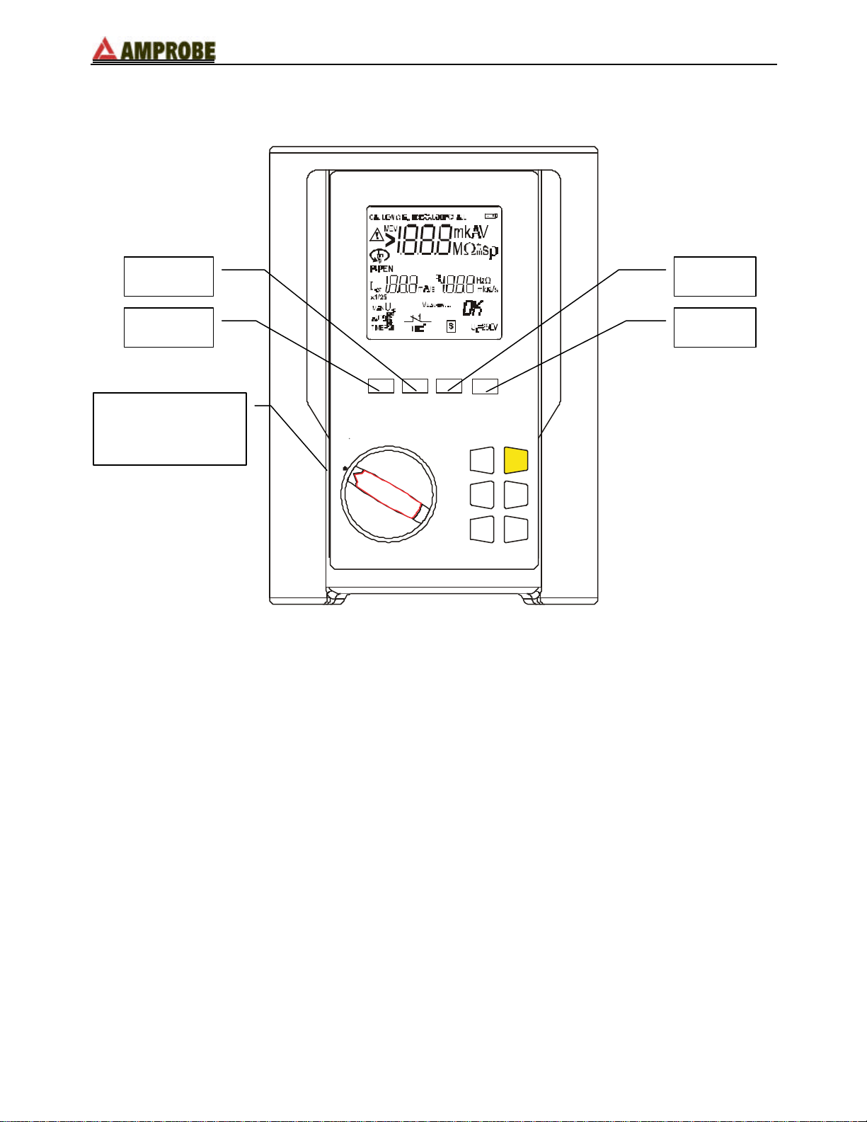
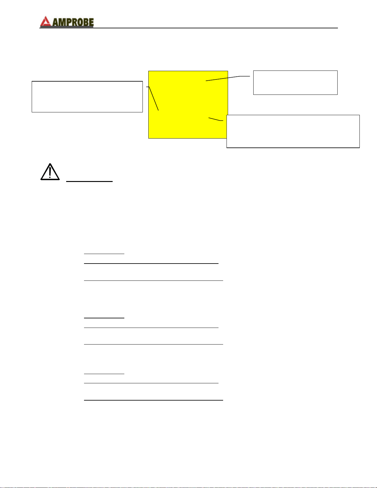
2.1. INSTRUMENT DESCRIPTION
ESC
DISP
SAVE
GO
CLR
Rotary switch:
GP-2 GeoTest
DIST
AVG
Permits selection of
the desired function
ss
tt
OFF
RCL
Figure 1: Front panel
EN - 6
Page 7
GP-2 GeoTest
AVG
GO
ESC
SAVE
DIST
RCL
DISP
CLR
F Displays the average value of the earth resistivity, calculated on the
basis of all valid measurements taken.
F Selects the distance "D" between the earth rods (ρ resistivity test).
ss
tt
F Increases the value of the parameter D; Scrolls through the recorded
test results; or Selects the unit m/ft.
F Decreases the value of the parameter D; Scrolls through the recorded
test results; or Selects the unit m/ft.
F Starts a measurement.
F Escape from (exit) the selected function or mode.
F Saves test results.
F Recall recorded test results.
F Displays recorded data from the selected memory location.
F Deletes:
- the average value of the measurements and the number of the
tests included in the average value calculations
- recorded test results from a specified memory location
EN - 7
Page 8

GP-2 GeoTest
3. PREPARING THE INSTRUMENT
3.1. INITIAL CHECK
This instrument has been carefully checked for proper electrical and mechanical function
prior to shipment. All possible precautions have been taken in order to deliver it in the best
possible condition.
Nevertheless, on receipt of the instrument we suggest that it be checked completely to
make sure that no damage has occurred in transit. Should you find anomalies please
contact the carrier immediately.
Please also make sure that the package contains all the accessories and parts listed in
paragraph 9.3.1. In case of discrepancies please contact your dealer.
Should it be necessary to return the instrument, please refer to the instructions in
paragraph 10.
3.2. POWER SUPPLY
The instrument is powered by 6 size 'AA' 1.5V batteries ( LR6– AM3 – MN 1500) not
included in the package.
For correct installation of the batteries see paragraph 8.2.
When the batteries are low the symbol appears. For replacement see paragraph 8.2.
3.3. CALIBRATION
The instrument complies with the standards mentioned in this manual. Its performance is
guaranteed for one year from the date of purchase.
3.4. STORAGE
To guarantee accurate measurements, after extended storage in severe environmental
conditions please allow the unit to normalize to proper ambient conditions.(see
environmental conditions listed at paragraph 9.2.1).
EN - 8
Page 9
GP-2 GeoTest
Secondary display on the
4. SWITCH FUNCTIONS
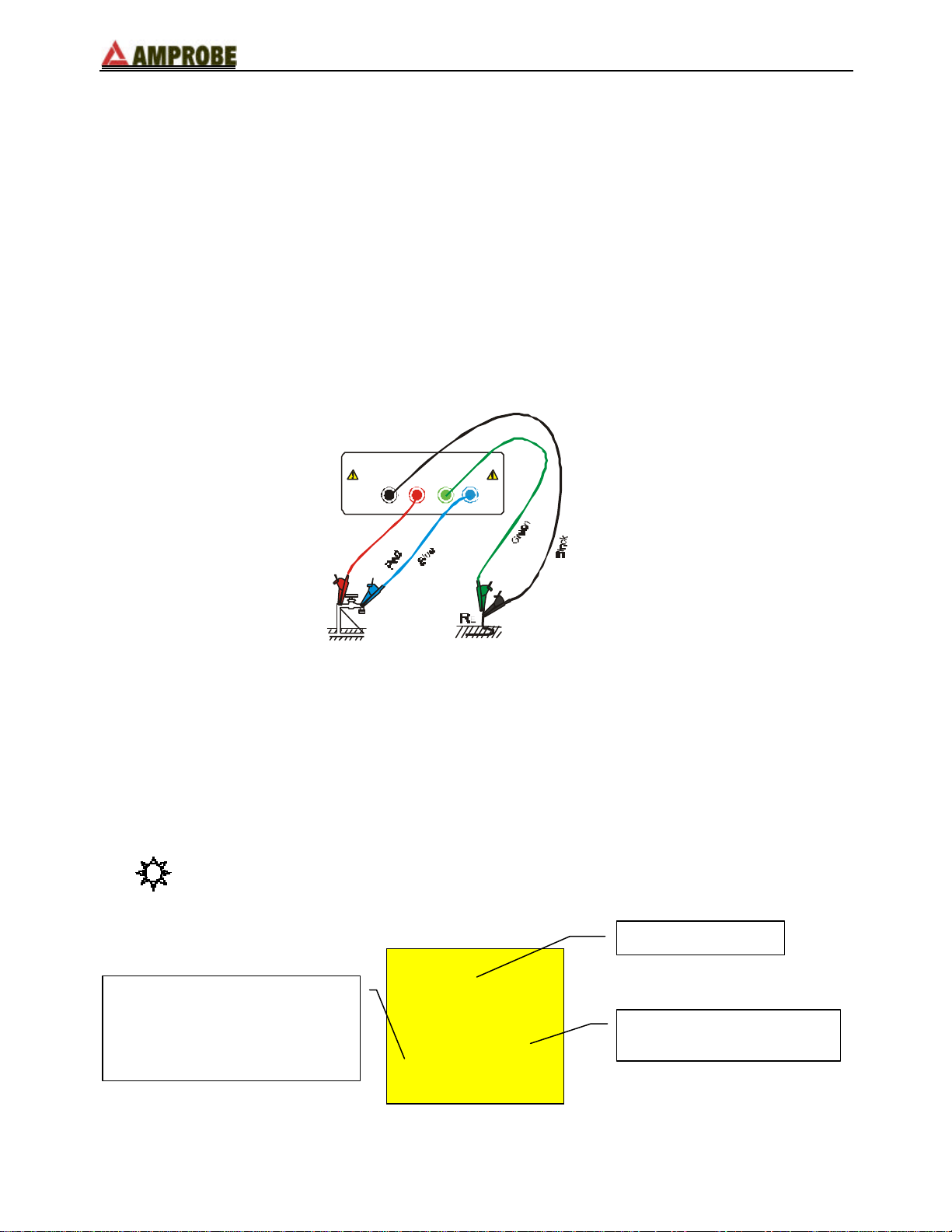
4.1. EARTH 2 WIRES
Whenever it is not possible to drive rods into the ground to take a 3-wire measurement, or
in case of TT installations it is possible to use the simplified 2-wire method (Figure 2)
which gives an excess (therefore safer) value.
To carry out the test a suitable auxiliary rod is necessary; a rod is “suitable” when its earth
resistance is negligible and it is independent of the earth equipment under test.
In Figure 2 a water pipe has been used as auxiliary rod. However, any metal body driven
into the ground can be used, provided that the above said requirements are met.
Although this test is not provided for by the CEI 64.8 standard at present, it gives a value,
which many 3-wire comparison tests have proved to be revealing for earth resistance.
H
ESE S
Figure 2: 2 wire earth resistance measurement
Measuring procedure:
F Insert the 4 connectors (black, red, blue and green) of the measuring cables into the
corresponding input terminals of the instrument (E, S, H, ES).
F Connect the alligator clips as shown in Figure 2.
F Position the switch on EARTH 2 WIRES.
Display appearance:
Main display
Secondary display on the lefthand side:
In this stage it displays the
eventual interfering voltage
present on the circuit
------
right-hand side
0 0 V - - -- - -
EN - 9
Page 10

GP-2 GeoTest
Average value of the resistance calculated
Value of the
resistance
GO
Press GO to take the measurement and read the result on the display. At the
end of the test, a screen similar to the following will be displayed.
NOTE! If you keep pressing GO, the instrument takes more measurements
consecutively. When a new value is acquired, the symbol Ω blinks on the main
display, the instrument emits a short sound and the counter shown on the
secondary display on the left-hand side is updated. This counter indicates the
number of measurements calculated on the basis of the average resistance
value.
No. of earth resistance
measurements
included in the
calculation of the
average resistance
0.960.96 ΩΩ
2 2 0.93 0.93 ΩΩ
as:
(Val1+Val2+…+Valn)/(No. measurements)
WARNING: When the message “Measuring” appears on the display, the
instrument is measuring. Do not disconnect the alligator
clips during the measurement.
Ex.: if the operator takes three measurements consecutively, the instrument will
display:
- 1st measurement:
main display = measured resistance value (Ex: 0.90Ω)
secondary display on the left-hand side = 001 (no. of measurements = 1
means that 1 earth measurement has been taken)
secondary display on the right-hand side = average of the measurements
taken (in case just one measurement has been taken the average value is
equal to the measured value, in this case 0.90Ω)
- 2nd measurement:
main display = measured resistance value (Ex: 0.96Ω)
secondary display on the left-hand side = 002 (no. of measurements = 2
means that 2 earth measurements have been taken consecutively)
secondary display on the right-hand side = average of the measurements
taken ((Val1+Val2)/no. of measurements = (0.90+0.96)/2 = 0.93Ω)
- 3rd measurement:
main display = measured resistance value (Ex: 0.93Ω)
EN - 10
Page 11
GP-2 GeoTest
SAVE
CLR
secondary display on the left-hand side = 003 (no. of measurements = 3
means that 3 earth measurements have been taken consecutively)
secondary display on the right-hand side = average of the measurements
taken ((Val1+Val2)/no. of measurements = (0.90+0.96+0.93)/3 = 0.93Ω)
NOTE! A test with a result over 700Ω is not inserted in the calculation of average value.
Example:
1st measurement
Main display: 1,07Ω
Secondary display on the left-hand side: 1
Secondary display on the right-hand side: 1,07Ω
2nd measurement
Main display: 4,15Ω
Secondary display on the left-hand side: 2
Secondary display on the right-hand side: 2,61Ω
3rd measurement (not inserted in the average value)
Main display: 1018Ω
Secondary display on the left-hand side: 2
Secondary display on the right-hand side: 2,61Ω
Press CLR if you want to cancel the average value of the resistance and the no.
of measurements which are included in the calculation (displayed on the
secondary displays on the right-hand side and on the left-hand side
respectively). A screen similar to the following will be displayed:
Last value of resistance
measured
0.960.96 ΩΩ
- - - - - - - - -- - -
The test results can be stored in memory by pressing SAVE (see paragraph
5.1).
NOTE! The resistance measurement is taken according to a 4-wire voltmetric method.
Therefore, it is not affected by the resistance value of the cables used: it is not
necessary to calibrate the cables or their extension.
EN - 11
Page 12
GP-2 GeoTest
Secondary display on the left-
Secondary display on the
GO
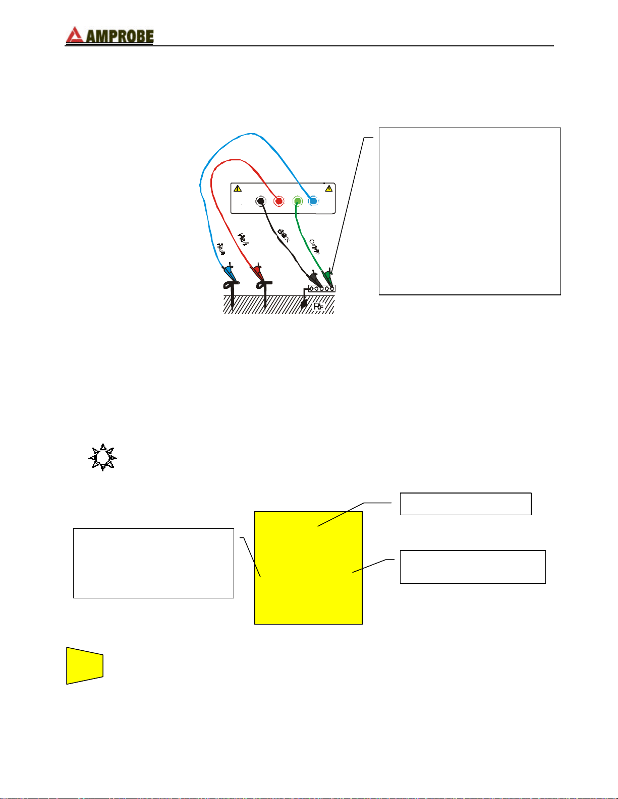
4.2. EARTH 3 WIRES
The measurement is taken according to what is prescribed for CEI 64.8, IEC 781, VDE
0413, EN61557-5 standards.
Small earth plant:
- current probe (terminal H, blue
wire) positioned a distance from
the earth equipment outline
E
CAT III
440 V P-N-PE
250 V
H
SH
H
ESES
ES
corresponding to five times the
diagonal of the area of the earth
equipment.
Large earth plant:
- current probe (terminal H, blue
wire) positioned a distance from
the earth equipment outline
corresponding the diagonal of
the area of the earth equipment.
Figure 3: 3 wires earth resistance measurement
Measuring procedure:
F Insert the 4 connectors (black, red, blue and green) of the cables into the
corresponding input terminals of the instrument (E, S, H, ES).
F Connect the alligator clips as shown in Figure 3.
F Position the switch to EARTH 3 WIRES.
Display appearance:
Main display
hand side:
In this mode it displays the
eventual interfering voltage
present on the circuit
------
right-hand side
0 0 V - - -- - -
Press GO to take the measurement and read the value on the display. At the
end of the test, a screen similar to the one below will be displayed.
NOTE! If you keep pressing GO, the instrument takes more measurements
consecutively. When a new value is displayed, the symbol Ω blinks on the main
display, the instrument emits a short sound and the counter shown on the
EN - 12
Page 13
secondary display on the left-hand side is updated. This counter indicates the
No. of earth resistance
Average value of the resistance calculated
Value of the resistance
quantity of measurements included in the calculation of the average resistance
value.
measurements included in the
calculation of the average resistance
WARNING: When the message “Measuring” appears on the display, the
instrument is measuring. Do not disconnect the alligator
clips during the measurement.
GP-2 GeoTest
measured
0.960.96 ΩΩ
2 2 0.93 0.93 ΩΩ
as:
(Val1+Val2+…+Valn)/(no. measurements)
Ex.: if the operator takes three measurements consecutively, the instrument will
display:
- 1st measurement:
main display = measured resistance value (Ex: 0.90Ω)
secondary display on the left-hand side = 001 (no. of measurements = 1
means that 1 earth measurement has been taken)
secondary display on the right-hand side = average of the measurements
taken (in case just one measurement has been taken the average value is
equal to the measured value, in this case 0.90Ω)
- 2nd measurement:
main display = measured resistance value (Ex: 0.96Ω)
secondary display on the left-hand side = 002 (no. of measurements = 2
means that 2 earth measurements have been taken consecutively)
secondary display on the right-hand side = average of the measurements
taken ((Val1+Val2)/no. of measurements = (0.90+0.96)/2 = 0.93Ω)
- 3rd measurement:
main display = measured resistance value (Ex: 0.93Ω)
secondary display on the left-hand side = 003 (no. of measurements = 3
means that 3 earth measurements have been taken consecutively)
secondary display on the right-hand side = average of the measurements
taken ((Val1+Val2)/no. of measurements = (0.90+0.96+0.93)/3 = 0.93Ω)
EN - 13
Page 14

GP-2 GeoTest
SAVE
CLR
Last resistance value
NOTE! A test with a result over 700Ω is not inserted in the calculation of average value.
Example:
1st measurement
Main display: 1,07Ω
Secondary display on the left-hand side: 1
Secondary display on the right-hand side: 1,07Ω
2nd measurement
Main display: 4,15Ω
Secondary display on the left-hand side: 2
Secondary display on the right-hand side: 2,61Ω
3rd measurement (not inserted in the average value)
Main display: 1018Ω
Secondary display on the left-hand side: 2
Secondary display on the right-hand side: 2,61Ω
Press CLR if you want to cancel the average resistance value and the no. of
measurements, which are included in the calculation (displayed on the
secondary displays on the right-hand side and on the left-hand side
respectively). A screen similar to the following will be displayed:
measured
0.960.96 ΩΩ
- - - - - - - - -- - -
NOTE! The resistance measurement is taken according to a 4-wire voltmetric method.
Therefore, it is not affected by the resistance value of the cable used: it is not
necessary to calibrate the cables or their extension.
The test results can be stored in memory by pressing SAVE (see paragraph
5.1)
EN - 14
Page 15

GP-2 GeoTest
a
a
S
H
4.3. "ρρ" MODE (Resistivity of the Earth)
The measurement is taken according to CEI 64.8, IEC 781, VDE 0413, EN61557-5
standards.
4.3.1. Selecting the units of measure
WARNING Whenever the units of measure are changed the
instrument will perform a hard reset and all the data in the
memory will be erased (see paragraph 6.1).
SELECT THE UNIT press and hold the "RCL" key and turn the rotary switch. The
instrument will display a screen that permits selection of the
correct measurement unit: m or ft (used to determine distance
between the ground rods) with the s or t keys. Press the
SAVE or ESC key to save the measurement unit selected.
NOTE! Regardless on the unit of distance D set up (either ft or m) the resistivity will
be automatically calculated in OhmMeters!
4.3.2. Operating Instructions
Measuring procedure:
F Drive the 4 earth rods into the ground at the same distance D. The distance D
between the rods is usually 3 to 30 ft (1 to 10 m).
The distance D between the rods determines the depth at which the earth
resistivity is measured. In order to identify the distance (and therefore depth)
corresponding to the lowest resistivity value, the test must be repeated several
times, positioning the rods at different distances. This depth will then have to be
physically reached by the rods of the earth equipment.
F Insert the 4 connectors (black, red, blue and green) of the cables into the
corresponding input terminals of the instrument (E, S, H, ES).
F Connect the alligator clips as shown in Figure 4.
E
CAT III
440 V P-N-PE
250 V
H
ES
a
Figure 4: 4 wire earth resistivity measurement
EN - 15
Page 16

F Position the switch on ρρ.
Value of the parameter D
Measured earth resistivity value
DIST
GO
ESC
Display appearance:
To select the distance D between the rods. This parameter can be chosen from
the following values (expressed in ft/m):
3, 6, 9, 12, 15, 18, 21, 24, 27, 30
GP-2 GeoTest
--- --- ρρ
0 0 V 010010 ft/m
tt
ss
1, 2, 3, 4, 5, 6, 7, 8, 9, 10
Press s or t to select the value of the parameter D:
006 006 ft/m ρρ
Press ESC to confirm the value previously set.
Press GO to take the measurement and read the value on the display. At the
end of the test a screen similar to the one following will be displayed.
36.536.5 ρρ
Measurement unit: Ωm
EN - 16
Page 17

GP-2 GeoTest
ESC
AVG
NOTE! Regardless on the unit of distance D, which is set up (either ft or m) the
resistivity will be automatically calculated in OhmMeters!
WARNING: When the message “Measuring” appears on the display, the
instrument is measuring. Do not disconnect the alligator
clips during the measurement.
NOTE! If you keep pressing GO, the instrument takes more measurements
consecutively. When a new value is acquired, the symbol Ωm blinks on the
main display, the instrument emits a short sound and, if the measured value is
inserted in the calculation of the average resistivity value, the message “Add”
appears on the secondary display on the right-hand side.
The earth resistivity value is an indispensable parameter to calculate the resistance value
of the rods, which will be used for the earth equipment (see paragraph 11.2).
Use AVG to display the average resistivity value measured. This key is enabled
only when the message “Add” appears on the secondary display on the lefthand side.
NOTE! The value of the resistivity corresponding to a resistance value over 700Ω is not
inserted in the calculation of average value.
Example:
1st measurement
Main display: 6.6 Ωm
Secondary display on the right-hand side: empty
2nd measurement
Main display: 26 Ωm
Secondary display on the right-hand side: Add
Press AVG: main display: 16.4 Ωm
secondary display on the left-hand side: 2
secondary display on the right-hand side: Add
3rd measurement (not inserted in the average value)
Main display: 6.3 kΩm
Secondary display on the right-hand side: Add
Press AVG: main display: 16.4Ωm
secondary display on the left-hand side: 2
secondary display on the right-hand side: Add
Use ESC to leave the screen showing the average value and return back to the
screen corresponding to the last measurement taken.
EN - 17
Page 18

GP-2 GeoTest
SAVE
This screen appears
This screen appears
Press SAVE to store the test results in memory (see paragraph 5.1).
Example:
You position the rods at a distance D of 3 feet and take 3 resistivity measurements:
7.7 7.7 ΩΩm ρρ 7.1 7.1 ΩΩm ρρ
AAdd
1st meas. 2nd meas. 3rd meas.
a) 1st measurement: you see the measured value but not the message “Add”.
b) 2nd measurement: you see the message “Add”. This means that the second
measurement is included in the calculation of the average; by pressing AVG you will
get also the average value calculated.
7.4 7.4 ΩΩm ρρ
002 A 002 Add
The "002" indicates that 7.4Ωm is the average value calculated as the average
between the two values previously measured.
Press ESC to return back to the screen corresponding to the second measurement.
Upon returning back to the second measurement, press CLR if you want to cancel the
average value calculated and the corresponding counter.
7.1 7.1 ΩΩm ρρ
AAdd
after press in AVG
c) 3rd measurement: as with point b) above, but the average value is calculated as
average between the three values measured.
The "003" indicates that 7.3Ωm is the average value calculated as average between
the three values previously measured.
7.3 7.3 ΩΩm ρρ
003 A 003 Add
EN - 18
after pressing AVG
Page 19

GP-2 GeoTest
SAVE
SAVE
rP indicates an high resistance value.
4.4. ANOMALOUS SITUATIONS WHICH CAN OCCUR DURING TESTS
WARNING
F
If the voltmetric circuit (red and green
cables) is interrupted, when pressing
GO the instrument will not read the
minimum voltage, therefore a screen
similar to the one beside appears.
Make sure that the terminals are
connected correctly and that the
voltmetric rod (red conductor) has not
been driven into a gravelly or scarcely
conductive ground. If necessary, pour
water around the rod.
νν - - -- - -
PP - - - - - -
THIS RESULT CANNOT BE SAVED.
F
If the amperometric circuit is
interrupted, when pressing GO the
instrument will not read the minimum
current, therefore a screen similar to
the one beside appears. Make sure
that the terminals are connected
correctly and that the amperometric
rod (blue conductor) has not been
driven into a gravelly or scarcely
conductive ground. If necessary, pour
water around the rod.
rC indicates an high resistance value.
THIS RESULT CANNOT BE SAVED.
WARNING
νν - - -- - -
- - - cc
EN - 19
Page 20

GP-2 GeoTest
SAVE
F
In case both the amperometric
circuit and the voltmetric circuit
are interrupted, when pressing GO
the instrument will not read the
minimum current nor the minimum
voltage, therefore a screen similar to
the one beside appears. Make sure
that the terminals are connected
correctly and that the amperometric
and voltmetric rods (blue and red
conductors) have not been driven
into a gravely or scarcely conductive
ground. If necessary, pour water
around the rod.
THIS RESULT CANNOT BE SAVED.
F
If the resistance measurement is
higher than the full scale of the
instrument, when pressing GO the
instrument performs the test and a
screen similar to the one beside
appears.
1999ΩΩ is the full scale of the instrument.
WARNING
νν - - -- - -
PP cc
rC and rP indicate an high resistance
value both for the voltmetric circuit and
for the amperometric circuit.
WARNING
νν>>1999 1999 ΩΩ
- - - - -- - - - -
--
F
If the resistivity measurement is
higher than the quantity
1999x6.28x(distance between the
rods selected) when pressing GO
the instrument performs the test and
a screen similar to the one beside
appears.
1999ΩΩ is the full scale of the instrument.
WARNING
νν>>1999 1999 ΩΩ
- - - - - -- - - - - -
EN - 20
Page 21

If the instrument measures an
SAVE
UC indicates the presence of too high
SAVE
F
interfering voltage higher than 30V
on the amperometric circuit, it does
not perform the test and a screen
similar to the one beside appears.
voltage on the amperometric circuit.
THIS RESULT CANNOT BE SAVED.
F
If the instrument measures an
interfering voltage higher than 5V
on the voltmetric circuit, it does not
perform the test and a screen similar
to the one beside appears.
GP-2 GeoTest
WARNING
νν - - -- - -
UC UC - - -
WARNING
νν - - -- - -
230230v - --
Interfering voltage measured.
THIS RESULT CANNOT BE SAVED.
EN - 21
Page 22

5. HOW TO SAVE, RECALL AND CANCEL DATA
SAVE
No. of memory location where the measure
5.1. TO SAVE: "SAVE" KEY
If you want to save the test results:
Press SAVE once.
GP-2 GeoTest
A screen similar to the one beside is
displayed for 3 seconds, the
instrument emits a sound, then the
screen corresponding to the last
measurement taken is displayed.
has been saved.
MEM
003003
EN - 22
Page 23

5.2. TO RECALL: "RCL" KEY
RCL
No. of last memory location occupied.
DISP
ESC
Message “rEc ord”:
DISP
If you want to review the test results:
1. Press RCL.
GP-2 GeoTest
If the memory contains
measurements, a screen similar to
the one beside will be displayed.
If the memory is empty, a screen
similar to the one beside will be
displayed.
the memory contains no values,
therefore it is impossible to recall them.
MEM
003003
MEM
EC C
tt
2. Press tt, ss to select the number of the memory location you wish to
ss
3. Press DISP to display the test result associated to the selected
tt
4. Press tt, ss to run over the saved results.
ss
5. Press DISP again to review the memory locations again.
6. Press ESC at any time to leave the memory and return to the selected
consult.
memory location.
measuring function.
EN - 23
Page 24

GP-2 GeoTest
RCL
No. of the last memory location occupied.
DISP
CLR
CLR
ESC
No. of the last memory location occupied. If you press CLR
5.3. TO CANCEL: "CLR" KEY
If you want to delete the test results:
1. Press RCL. A screen similar to the following will be displayed:
MEM
33
tt
2. Press tt, ss to select the number of the memory location.
ss
NOTE! when you cancel data the instrument cancels all the saved
data from the SELECTED location up to the last memory
location occupied.
3. Press DISP to display the test result associated with the selected
memory location. Press DSP again to review the memory locations.
4. Press CLR. The secondary displays are blinking.
MEM
No. of last memory location which will be
cancelled.
twice the instrument will cancel the memory locations from
no. 2 to no. 8.
At this point you have two possibilities:
0202
08 08 C C ii
Press CLR again to cancel the test results from the
selected location (main display) through the last
location saved (secondary display on the left-hand
side)
Press ESC once to abort the cancellation and return to
the number of the memory location.
EN - 24
Page 25

Press ESC again to return to the selected measuring function.
ESC
Ex.: 97 test results have been saved.
You want to clear from the 43rd to the 97
- Press RCL.
- Select the 43rd memory location using t and s.
- Press CLR. The symbol “ C C i i ” will blink on the secondary display on the
right-hand. The number 43 will appear on the main display and the number
97 will appear on the secondary display on the left-hand side.
- Press CLR to erase saved data from the 43rd to the 97th location.
th
location.
GP-2 GeoTest
EN - 25
Page 26

GP-2 GeoTest
6. RESET AND DEFAULT PARAMETERS
This paragraph describes the HARD RESET procedure and the default parameters set
when a HARD RESET procedure is performed.
6.1. HARD RESET
NOTE! BEFORE RESETTING, TRANSFER ALL SAVED DATA TO A PC.
1. Depress and hold the CLR key while turning on the instrument by rotating the switch.
2.
This screen is displayed for 5
seconds.
The reset has been performed.
The screen corresponding to the
selected function is displayed.
H E SE
NOTE! As a consequence of the HARD RESET procedure all the saved is deleted
and the parameter DST (distance between the rods, resistivity measurement)
returns to the default value.
6.2. DEFAULT PARAMETERS
The default parameters automatically set when a HARD RESET procedure is performed
are the following:
6.2.1. Default parameters
Parameter Default parameter set with the RESET procedure
Parameter DST = distance
between the rods, resistivity
measurement
Test results contained in the
memory
DST = 1
Memory empty
EN - 26
Page 27

GP-2 GeoTest
7. CONNECTING THE INSTRUMENT TO A PC
Connect the instrument to a PC through the RS-232 port with the supplied cable.
Refer to software manual for information how to set up software for download.
In order to transfer recorded data to a PC follow this procedure:
Position the switch on RS232.
Proceed as indicated in the manual of the management software.
SeSe
NOTE! the transmission speed of the GP-2 is 9600 baud (see software manual).
NOTE! On RS232, the instrument will switch off automatically 2 minutes after the last
selecting command from a PC. .
EN - 27
Page 28

GP-2 GeoTest
8. MAINTENANCE
8.1. GENERAL
GP-2 GeoTest is a precision instrument. During its use and for its storage follow the
recommendations and instructions contained in this manual in order to avoid possible
damage or danger.
Never use the instrument in environments with a high humidity or temperature.
Do not expose the instrument to direct sunlight.
Always turn off the instrument after use. If you expect to not use it for extended periods,
remove the batteries.
8.2. BATTERY REPLACEMENT
When the symbol appears, the batteries must be replaced.
WARNING: Only qualified technicians can perform this operation.
Before replacing the fuse/fuses disconnect the alligator clips
from circuit under voltage in order to avoid electrical shocks.
The tester is capable of keeping the values stored for
approx. 10 minutes.
1. Disconnect the cables from the input terminals.
2. Set the switch to the OFF position.
3. Remove the battery cover screws and then remove the cover.
4. Replace the batteries with 6 new ones of the same type: 1.5V– AA (– LR6– AM3 – MN
1500).
5. Reposition the cover and replace the screws.
8.3. CLEANING
Use a soft dry cloth to clean the instrument. Do not use wet clothes, solvents, water etc.
EN - 28
Page 29

9. TECHNICAL SPECIFICATIONS
9.1. TECHNICAL FEATURES
Resistance measurement
GP-2 GeoTest
Range (**)
(ΩΩ)
Resolution
(ΩΩ)
Accuracy (*)
0.01 ÷ 19.99 0.01
20.0 ÷ 199.9 0.1
200 ÷ 1999
(*) If RP > 100RE and/or RC > 100RE , RP > 50kΩ and/or RC > 50kΩ, if the instrument carries out the test
the accuracy of the instrument is ±(10%Reading)
RP = resistance of the voltage circuit
RC = resistance of the current circuit
RE = earth resistance
(**) Automatic selection of the range.
Measuring frequency 125Hz / 75Hz/ 41.66Hz
Measuring current 10mA
Open-terminal measuring voltage 25Vrms
Waveform of measuring voltage: sine wave
Interfering voltage:
- amperometric circuit: the measurement is taken with the stated accuracy if the interfering voltage is ≤ 3V,
while for interfering voltages between 3 and 30V inclusive, the accuracy decreases progressively; with an
interfering voltage of about 30V the instrument does not perform the test.
- voltmetric circuit: the measurement is taken if the interfering voltage is ≤ 3V; in case of higher voltages
the instrument does not perform the test.
1
±(2% reading + 3 digits)
EN - 29
Page 30

GP-2 GeoTest
Resistivity measurement ρρ
Range (**) Resolution Accuracy (*)
0.6-125.6 Ωm 0.1 Ωm
0.125 – 1.256 kΩm 0.001 kΩm
1.25-19.99 kΩm 0.01 kΩm
20.0 – 199.9 kΩm 0.1 kΩm
(*) If RP > 100RE and/or RC > 100RE , RP > 50kΩ and/or RC > 50kΩ, if the instrument carries out the test
the accuracy of the instrument is ±(10%Reading)
RP = resistance of the voltage circuit
RC = resistance of the current circuit
RE = earth resistance
ρ = 2πDRE = calculated resistivity
(**) Automatic selection of the range
Measuring frequency 125Hz / 75Hz/ 41.66Hz
Measuring current 10mA
Open-terminal measuring voltage 25Vrms
Waveform of measuring voltage: sine wave
Interfering voltage:
- amperometric circuit: the measurement is taken with the stated accuracy if the interfering voltage is ≤ 3V,
while for interfering voltages between 3 and 30V inclusive, the accuracy decreases progressively; with an
interfering voltage of about 30V the instrument does not perform the test.
- voltmetric circuit: the measurement is taken if the interfering
voltage is ≤ 3V; in case of higher voltages the instrument does
not perform the test.
±(2% reading + 3 digits)
Interfering voltage measurement
Range
(V)
500 1
Safety standards
This instrument complies with EN 61010, EN 61557-1, EN 61557-5 standards.
Insulation class 2, double insulation
Pollution 2
Maximum altitude 2000m
Surge voltage category CAT III 250V (phase to earth)
Resolution
(V)
Accuracy
±(2% reading + 2 digits)
EN - 30
Page 31

GP-2 GeoTest
General features
Mechanical features
Dimensions: 222 (L) x 162 (W) x 57 (H) mm
Weight (batteries included): about 1000g
Power supply
Batteries: 6 batteries 1.5 V size AA ( LR6 –– AM3 – MN
1500)
Low battery indication: The symbol appears on the display when the
battery voltage is low.
Battery life: about 300 measurements
Fusible Link: F 100 mA (not accessible to the operator)
Auto Power Off: the instrument will automatically switch off 2
minutes after last selecting a function or PC
command.
Display
Features: standard LCD 65mm x 65mm.
Memory: 999 memory locations
Interfaces: opto-insulated serial output RS232 to transfer data
to a PC.
EN - 31
Page 32

GP-2 GeoTest
9.2. OPERATING CONDITIONS
9.2.1. Environmental conditions
Reference temperature: 73 ± 41 F (23° ± 5°C)
Operating temperature: 14 ± 122 F (-10°C ÷ 50 °C)
Relative humidity: <80%
Storage temperature: -4 ± 140 F (-20 ÷ 60 °C)
Storage humidity: <70%
9.2.2. EMC
This instrument has been designed in compliance with the EMS standards in force and its
compatibility has been tested for:
Irradiated emissions: EN55011
Immunity: EN50140, EN 61000
Electrostatic discharges: EN61000-4-2
R.F. range: EN50140
Fast transient: EN61000-4-4
9.3. ACCESSORIES
9.3.1. Standard and optional accessories
Standard accessories * Code
- 1 carrying case containing:
- 4 earth rods
- 4 cables banana-crocodile
Carrying case GP-2CC
Optical serial cable C2000
Software and manual www.amprobe.com
GP-2CON
EN - 32
Page 33

GP-2 GeoTest
10. SERVICE
10.1. WARRANTY
This instrument is guaranteed against any defects in material and manufacturing for one
year, in compliance with the general sale terms and conditions. During the warranty period
all defective parts may be replaced, but the manufacturer reserves the right to repair or
replace the product.
If the instrument is to be returned, its transport expenses must at the customer's expense.
Shipping instructions may be obtained by contacting the factory. A Return Material
Authorization (RMA) number must be obtained from the factory prior to return.
A report should accompany the returned product, stating the reason(s) for return.
The unit should be packed in its original carton or equivalent; any damage that may be due
to non-original packing shall be charged to the customer.
The manufacturer disclaims any responsibility for damages caused to people and/or
objects.
The Warranty is not applicable in the following cases:
• Any repair and/or replacement of accessories and the battery (not covered by the
guarantee).
• Any repair that might be necessary as a consequence of a misuse of the instrument or
of its use with non-compatible devices.
• Any repair that might be necessary as a consequence of improper packaging.
• Any repair that might be necessary as a consequence of attempted service carried out
by unauthorized personnel.
• Any change to the instrument carried out without the express authorization of the
manufacturer.
• Use not intended for as per the instrument specifications or in the instruction manual.
The content of this manual cannot be reproduced in any form whatsoever without express
authorization of the manufacturer.
This product is patented and its trade mark registered. The manufacturer reserves
the right to modify the product specifications without prior notification.
10.2. SERVICE
If the instrument does not work properly, before returning, check the cables and replace
them, if necessary.
Should the instrument still operate improperly, check that the operation procedure is
correct and corresponds to the instructions given in this manual.
If the instrument is to be returned, its transportation is at the customer’s expense. Shipping
instructions may be obtained by contacting the factory. A Return Material Authorization
(RMA) number must be obtained from the factory prior to return.
EN - 33
Page 34

GP-2 GeoTest
A report should accompany the returned product, stating the reason(s) for return.
The unit should be packed in its original carton or equivalent; any damage that may be due
to non-original packing shall be charged to the customer.
The manufacturer disclaims any responsibility for damages caused to people and/or
objects.
EN - 34
Page 35

GP-2 GeoTest
11. PRACTICAL REPORTS FOR ELECTRICAL TESTS
11.1. EARTH RESISTANCE MEASUREMENT
PURPOSE OF THE TEST
This test is carried out to make sure that the protective device is coordinated with the earth
resistance value. You cannot take off hand a limit earth resistance value as a reference for
the test result: occasionally you must make sure that the prescribed coordination is
respected.
EQUIPMENT PARTS TO BE TESTED
The earth equipment and its working conditions. The test must be carried out without
disconnecting the earth references.
ADMISSIBLE VALUES
The earth resistance value, however measured, must meet the following requirement:
RE < 50 / I
where: RE= measured resistance of the earth equipment. The value can be
determined with the following tests:
- earth resistance with 3-wire voltmetric method
- loop impedance (see (*))
- 2-wire earth resistance (see (**))
- 2-wire earth resistance in the socket (see (**))
- earth resistance given by the contact voltage Ut (see (**)).
- earth resistance given by tripping time of RCDs (A, AC), RCD S (A,
AC) (see (**)).
Ia= tripping time in 5s increments of the automatic switch; nominal tripping
current of the RCD (in case of RCD S 2 I∆n).
50= Limit safety voltage (reduced to 25V for special places).
(*) In presence of an RCD the test must be carried out on the RCD
upstream or downstream, bypassing it to avoid its intervention.
(**) These methods, even if not yet prescribed for by the CEI 64.8 standard,
give values which many 3-wire comparison tests proved to be revealing
for earth resistance.
a
EN - 35
Page 36

GP-2 GeoTest
Black
Green
Use several rods in parallel and
EXAMPLE OF EARTH RESISTANCE MEASUREMENT
You must test equipment protected by a RCD at 30 mA. Measure the earth resistance
according to one of the above-described methods. In order to check whether the
resistance complies to the standards in force, multiply the value for 0.03A (30 mA). If the
result is lower than 50V (or 25V for special places) the equipment is to be considered as
coordinated as it meets the above stated requirement.
In case of RCDs at 30 mA (used for nearly the totality of civil equipment) the maximum
earth resistance admitted is 50/0.03=1666###. This also permits use of the simplified
methods described, which give an approximate value (although not extremely precise) for
the calculation of the coordination.
VOLTAMPEROMETRIC METHOD
For small earth plant
Let a current circulate between the earth rod and a current probe positioned at a distance
from the earth equipment outline corresponding to five-times the diagonal of the area delimiting the earth equipment (see Figure 5). Position the voltage probe halfway between
the earth rod and the current probe, then measure the voltage between the two.
moisten the surrounding ground if
the instrument is not able to supply
the current necessary to perform the
test because of an high earth
resistance.
Figure 5: Earth resistance measurement (voltamperometric method
Red
Blue
for small earth plant)
EN - 36
Page 37

GP-2 GeoTest
Black
Green
For large earth plants
This procedure is also based on the voltamperometric method, but it is mainly used when
it is difficult to position the auxiliary current rod at a distance corresponding to five-times
the diagonal of the area of the earth equipment. Position the current probe at a distance
equal to the diagonal of the area of the earth equipment (see Figure 6). To make sure that
the voltage probe is positioned outside the area affected by the rod under test, take more
measurements, first positioning the voltage probe halfway between the rod and the current
probe, then moving the probe both towards the earth rod and towards the current probe.
Use several rods in parallel and
moisten the surrounding ground if
the instrument is not able to
supply the current necessary to
perform the test because of an
high earth resistance.
Red
Blue
Figure 6: earth resistance measurement (voltamperometric method for big earth
plant)
EN - 37
Page 38

GP-2 GeoTest
Black
Green
a
a
a
2nd measurement:
11.2. EARTH RESISTIVITY MEASUREMENT
PURPOSE OF THE TEST
This test is intended to analyze the resistivity value of the ground in order to define the
type of rods to be used.
EQUIPMENT PARTS TO BE TESTED
For the resistivity test admissible values do not exist. The various values measured by
positioning the rods at growing distances “a” must be quoted in a graph. According to the
resulting curve, suitable rods will be chosen. As the test result can be affected by metal
parts buried (such as pipes, cables or other rods), in case of doubt take a second
measurement positioning the rods at an equal distance "a", but rotating their axis by 90°.
compared to the previous
measurement the rods are
rotated by 90°.
1st measurement:
the rods are positioned
at a distance “a”
90°
aaa
R
e
d
B
l
a
c
k
G
Blue
Red
B
l
u
r
e
e
e
n
The resistivity value is calculated with the following formula:
where: ρ= specific resistivity of the ground (Ωm)
ρ=2πaR
a= distance between the rods (ft/m)
R= resistance measured by the instrument (Ω)
EN - 38
Page 39

GP-2 GeoTest
The measuring method allows definition of the specific resistance up to the depth
approximately corresponding to the distance “a” between the rods. If you increase the
distance “a” you can reach deeper ground layers and check the ground homogeneity. After
several ρ measurements, at growing distances “a”, you can trace a profile like the following
ones, according to the most suitable rod chosen:
Curve1: as ρ decreases only in depth, it is possible to use only a rod in depth.
Curve2: as ρ decreases only until the depth A, it is not useful to increase the depth of the
rod beyond A.
Curve3: even at a superior depth, ρ does not decrease, therefore a ring rod must be used.
(Ωm)
(ft / m)
APPROXIMATE EVALUATION OF THE CONTRIBUTION OF INTENTIONAL RODS (6412 2.4.1)
The resistance of a rod Rd can be calculated with the following formulas (ρ = average
resistivity of the ground).
a) resistance of a vertical rod
Rd = ρ / L
L= length of the element touching the ground
b) resistance of an horizontal rod
Rd = 2ρ / L
L= length of the element touching the ground
c) resistance of linked elements
The resistance of a complex system with more elements in parallel is always higher
than the resistance which could result from a simple calculation of elements in
EN - 39
Page 40

GP-2 GeoTest
parallel, especially if those elements are close and therefore interactive. For this
reason, in case of a linked system the following formula is quicker and more effective
than the calculation of the single horizontal and vertical elements:
Rd = ρ / 4r
r= radius of the circle which circumscribes the link.
EN - 40
Page 41

AMPROBE
MIAMI, FL
Tel: 305 423 7500
Fax: 305 423 7554
www.amprobe.com
Tecnical Support:
www.amprobe.com
800 327 5060
 Loading...