

Page 1

FG2C-UA/FG3C-UA
Function Generator
User Manual
• Mode d’emploi
• Bedienungshandbuch
• Manuale d’Uso
• Manual de uso
Page 2

Page 3

FG2C-UA/FG3C-UA
Function Generator
Users Manual
• Mode d’emploi
• Bedienungshandbuch
• Manuale d’ Uso
• Manual de uso
PN 2099447
April 2007, Rev.2
©2007 Amprobe Test Tools.
All rights reserved. Printed in China
Page 4

Page 5

Limited Warranty and Limitation of Liability
Your Amprobe product will be free from defects in material and workmanship for 1 year from the date of
purchase. This warranty does not cover fuses, disposable batteries or damage from accident, neglect, misuse,
alteration, contamination, or abnormal conditions of operation or handling. Resellers are not authorized to extend
any other warranty on Amprobe’s behalf. To obtain service during the warranty period, return the product with
proof of purchase to an authorized Amprobe Test Tools Service Center or to an Amprobe dealer or distributor.
See Repair Section for details. THIS WARRANTY IS YOUR ONLY REMEDY. ALL OTHER WARRANTIES - WHETHER
EXPRESS, IMPLIED OR STAUTORY - INCLUDING IMPLIED WARRANTIES OF FITNESS FOR A PARTICULAR PURPOSE OR
MERCHANTABILITY, ARE HEREBY DISCLAIMED. MANUFACTURER SHALL NOT BE LIABLE FOR ANY SPECIAL, INDIRECT,
INCIDENTAL OR CONSEQUENTIAL DAMAGES OR LOSSES, ARISING FROM ANY CAUSE OR THEORY. Since some states
or countries do not allow the exclusion or limitation of an implied warranty or of incidental or consequential
damages, this limitation of liability may not apply to you.
Beschränkte Gewährleistung und Haftungsbeschränkung
Es wird gewährleistet, dass dieses Amprobe-Produkt für die Dauer von einem Jahr ab dem Kaufdatum frei von
Material- und Fertigungsdefekten ist. Diese Gewährleistung erstreckt sich nicht auf Sicherungen, Einwegbatterien
oder Schäden durch Unfälle, Nachlässigkeit, Missbrauch, Änderungen oder abnormale Betriebsbedingungen bzw.
unsachgemäße Handhabung. Die Verkaufsstellen sind nicht dazu berechtigt, diese Gewährleistung im Namen
von Amprobe zu erweitern. Um während der Gewährleistungsperiode Serviceleistungen zu beanspruchen, das
Produkt mit Kaufnachweis an ein autorisiertes Amprobe Test Tools Service-Center oder an einen AmprobeFachhändler/-Distributor einsenden. Einzelheiten siehe Abschnitt „Reparatur“ oben. DIESE GEWÄHRLEISTUNG
STELLT DEN EINZIGEN UND ALLEINIGEN RECHTSANSPRUCH AUF SCHADENERSATZ DAR. ALLE ANDEREN
GEWÄHRLEISTUNGEN - VERTRAGLICH GEREGELTE ODER GESETZLICHE VORGESCHRIEBENE - EINSCHLIESSLICH DER
GESETZLICHEN GEWÄHRLEISTUNG DER MARKTFÄHIGKEIT UND DER EIGNUNG FÜR EINEN BESTIMMTEN ZWECK,
WERDEN ABGELEHNT DER HERSTELLER ÜBERNIMMT KEINE HAFTUNG FÜR SPEZIELLE, INDIREKTE, NEBEN- ODER
FOLGESCHÄDEN ODER VERLUSTE, DIE AUF BELIEBIGER URSACHE ODER RECHTSTHEORIE BERUHEN. Weil einige
Staaten oder Länder den Ausschluss oder die Einschränkung einer implizierten Gewährleistung sowie von Begleitoder Folgeschäden nicht zulassen, ist diese Gewährleistungsbeschränkung möglicherweise für Sie nicht gültig.
Garantía limitada y Limitación de responsabilidad
Su producto Amprobe estará libre de defectos de material y mano de obra durante 1 año a partir de la fecha de
adquisición. Esta garantía no cubre fusibles, baterías descartables o daños que sean consecuencia de accidentes,
negligencia, uso indebido, alteración, contaminación o condiciones anormales de operación o manipulación.
Los revendedores no están autorizados a extender ninguna otra garantía en nombre de Amprobe. Para obtener
servicio durante el período de garantía, regrese el producto con una prueba de compra a un centro de servicio
autorizado por Amprobe de equipos de comprobación o a un concesionario o distribuidor de Amprobe. Consulte
la sección Reparación que aparece más arriba para obtener detalles. ESTA GARANTÍA CONSTITUYE SU ÚNICO
RESARCIMIENTO. TODAS LAS DEMÁS GARANTÍAS, TANTO EXPRESAS, IMPLÍCITAS O ESTATUTARIAS, INCLUYENDO
LAS GARANTÍAS IMPLÍCITAS DE ADECUACIÓN PARA UN PROPÓSITO DETERMINADO O COMERCIABILIDAD, QUEDAN
POR LA PRESENTE DESCONOCIDAS. EL FABRICANTE NO DEBERÁ SER CONSIDERADO RESPONSABLE DE NINGÚN
DAÑO O PÉRDIDA TANTO ESPECIALES, INDIRECTOS, CONTINGENTES O RESULTANTES QUE SURJAN DE CUALQUIER
CAUSA O TEORÍA. Debido a que ciertos estados o países no permiten la exclusión o limitación de una garantía
implícita o de los daños contingentes o resultantes, esta limitación de responsabilidad puede no regir para usted.
Limites de garantie et de responsabilité
Amprobe garantit l’absence de vices de matériaux et de fabrication de ce produit dans des conditions normales
d’utilisation et d’entretien pendant une période d’un an prenant effet à la date d’achat. Cette garantie ne
s’applique pas aux fusibles, aux piles jetables ni à tout produit mal utilisé, modifié, contaminé, négligé ou
endommagé par accident ou soumis à des conditions anormales d’utilisation et de manipulation. Les distributeurs
agréés par Amprobe ne sont pas autorisés à appliquer une garantie plus étendue au nom de Amprobe. Pour
bénéficier de la garantie, renvoyez le produit accompagné d’un justificatif d’achat auprès d’un centre de services
agréé par Amprobe Test ou du distributeur ou du revendeur Amprobe. Voir la section Réparation ci-dessus
pour tous les détails. LA PRESENTE GARANTIE EST LE SEUL ET EXCLUSIF RECOURS TOUTES AUTRES GARANTIES,
EXPLICITES, IMPLICITES OU STATUTAIRES, NOTAMMENT LE CAS ECHEANT LES GARANTIES DE QUALITE MARCHANDE
OU D’ADAPTATION A UN OBJECTIF PARTICULIER SONT EXCLUES PAR LES PRESENTES. LE FABRICANT NE SERA EN
AUCUN CAS TENU RESPONSABLE DE DOMMAGES PARTICULIERS, INDIRECTS, ACCIDENTELS OU CONSECUTIFS, NI
D’AUCUNS DEGATS OU PERTES DE DONNEES, SUR UNE BASE CONTRACTUELLE, EXTRA-CONTRACTUELLE OU AUTRE.
Etant donné que certains pays ou états n’admettent pas les limitations d’une condition de garantie implicite, ou
l’exclusion ou la limitation de dégâts accidentels ou consécutifs, les limitations et les exclusions de cette garantie ne
s’appliquent pas obligatoirement à chaque acheteur.
Page 6

Page 7
ENGLISH
N
L
E
CONTENTS
CERTIFICATIONS AND PRECAUTIONS ...............................................................................................................1
FOR UNITED KINGDOM ONLY .......................................................................................................................... 1
PREPARATION FOR USE – UNPACKING............................................................................................................. 2
INTRODUCTION ................................................................................................................................................. 2
FEATURES COMPARISON TABLE FOR MODELS ................................................................................................ 2
CONTROL DESCRIPTIONS .................................................................................................................................. 7
USAGE PROCEDURES ......................................................................................................................................... 8
PRECAUTION ITEMS .......................................................................................................................................... 8
FUSE REPLACEMENT (See Figs. 2 and 4) ........................................................................................................... 9
MAINTENANCE .................................................................................................................................................. 9
SPECIFICATIONS ............................................................................................................................................... 10
CERTIFICATIONS AND PRECAUTIONS
This instrument is EN61010-1 certified. All inputs are protected against continuous overload conditions up to the
limits of each function’s stated input protection (see specifications). Never exceed these limits or the ratings marked
on the instrument itself. Always inspect your Function Generator, test leads and accessories for signs of damage
or abnormality before every use. If an abnormal condition exists (broken or damaged test leads, cracked case,
display not reading, etc.), do not use. Never ground yourself when taking measurements. Do not touch exposed
metal pipes, outlets, fixtures, etc., which might be at ground potential. Keep your body isolated from ground and
never touch exposed wiring, connections, test probe tips, or any live circuit conductors. Do not operate instrument
in an explosive atmosphere (flammable gases, fumes, vapor, dust.) Do not use this or any piece of test equipment
without proper training.
DANGER High Voltage
ATTENTION Refer to Manual
Protective Conductor Terminal
Frame or Chassis Terminal
Complies with EU directives
WARNING: To avoid electrical shock, the
power cord protective grounding conductor
must be connected to ground.
CAUTION: To avoid damaging the instrument,
do not use it in a place where ambient
temperature exceeds 40°C.
CAUTION:To avoid damaging the instrument,
do not input more than 15VDC to VCF.
CAUTION: To avoid damaging the instrument,
do not input more than 150VAC to Frequency
Counter (FG3C-UA only).
CAUTION:To avoid damaging the instrument,
do not input more than 10Vpp during EXT
modulation operation (FG3C-UA only)
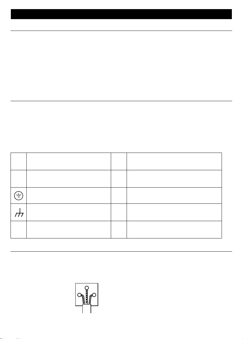
FOR UNITED KINGDOM ONLY
NOTE: This lead/appliance must only be wired by competent persons
WARNING: THIS APPLIANCE MUST BE EARTHED
IMPORTANT: The wires in this lead are coloured in accordance with the following code:
Green/ Yellow: Earth
Blue: Neutral
Brown: Live (Phase)
1
Page 8

As the colours of the wires in main leads may not correspond with the colours marking identified in your plug/
appliance, proceed as follows:
• The wire which is coloured Green & Yellow must be connected to the Earth terminal marked with the letter E
or by the earth symbol or coloured Green or Green & Yellow.
• The wire which is coloured Blue must be connected to the terminal which is marked with the letter N or
coloured Blue or Black.
• The wire which is coloured Brown must be connected to the terminal marked with the letter L or P or
coloured Brown or Red.
• If in doubt, consult the instructions provided with the equipment or contact the supplier. This cable/appliance
should be protected by a suitably rated and approved HBC mains fuse : refer to the rating information on the
equipment and/or user instructions for details. As a guide, cable of 0.75mm should be protected by a 3A or 5A
fuse. Larger conductors would normally require 13A types, depending on the connection method used.
• Any moulded mains connector that requires removal /replacement must be destroyed by removal of any
fuse & fuse carrier and disposed of immediately, as a plug with bared wires is hazardous if engaged in a live
socket. Any rewiring must be carried out in accordance with the information detailed on this label.
PREPARATION FOR USE – UNPACKING
Your shipping carton should include the Function Generator, 1 meter long BNC to mini- alligator clip test lead, one
115V power cord, one 230V power cord, one spare fuse for 115V operation, one spare fuse for 230V operation, and
this manual. If any of the items are damaged or missing, immediately return the complete package to the place of
purchase for an exchange.
INTRODUCTION
The FG2C-UA and FG3C-UA Function Generators are stable low distortion instruments that generate sine, triangle,
and square waveforms in frequencies up to 3 MHz. The FG2C-UA has amplitude, offset, and duty cycle controls. The
outputs are Main(50Ω) and logic(TTL and CMOS). The FG3C-UA has the same capabilities plus internal Sweep(Log/
Linear), Modulation (AM/FM), external VCF/MOD and counter inputs and GCV output. The counter can be switched
to measure and display the frequency of an external signal up to 150 MHz.
FEATURES COMPARISON TABLE FOR MODELS
FEATURE FG2C-UA FG3C-UA
AM/FM modulation na X
SWEEP control na X
COUNTER input na X
GCV Output na X
TTL/CMOS output X X
VCF input X X
Duty Cycle Control X X
2
Page 9
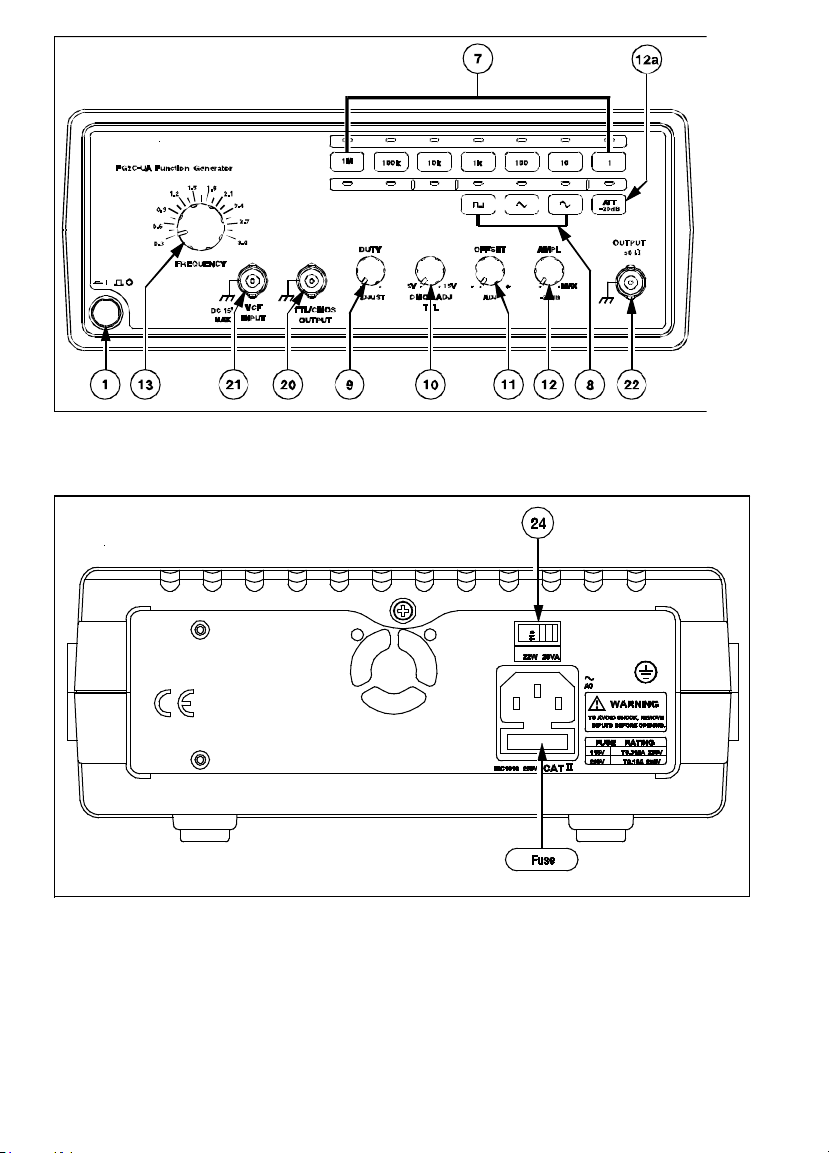
Fig. 1 FG2C-UA Front Panel
Fig.2 Rear Panel
3
Page 10
P O W E R
M O
D
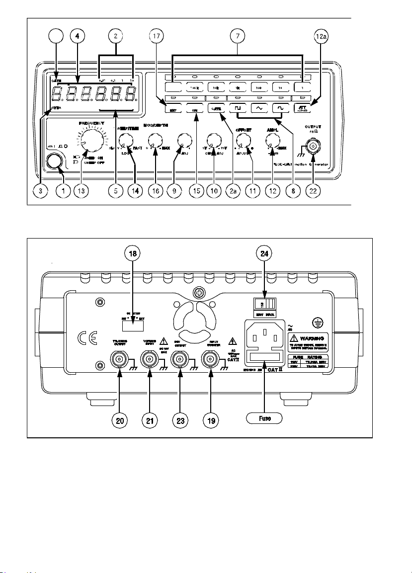
Fig. 3 FG3C-UA Front Panel
Fig 4. FG3C-UA Rear Panel
4
Page 11
CONTROL DESCRIPTIONS
Front and Rear Panel
1. Power Switch
Applies line power to the FG2C-UA/FG3C-UA power supply.
2. Gate Interval Indicator (FG3C-UA)
Gate interval indicator (the gate interval of internal counter is 0.01 second).
2a. Gate Time Selector (FG3C-UA)
Press this button to change gate time when use EXTernal counter mode. The sequence is 0.01s, 0.1s, 1s, or 10s
selected by pressing this button.
3. Over Range Indicator (FG3C-UA)
In the external counter mode, the indicator is illuminated when the output frequency is greater than the
range selected.
4. Counter Display (FG3C-UA)
Shows the external frequency via a 6 digit green display, and the internal frequency via a 5 digit green
display.
5. Frequency Indicator (FG3C-UA)
Indicates the current frequency value multiplier.
6. Gate Time Indicator (FG3C-UA)
Flashes at the beginning of each gating interval.
7. Frequency Range Selector
Select the required frequency range by pressing the relevant push button on the panel as shown in Table 1 .
Table 1.
Push Button Frequency Range
1 0.3Hz to 3Hz
10 3Hz to 30Hz
100 30Hz to 300Hz
1k 300Hz to 3kHz
10k 3kHz to 30kHz
100k 30kHz to 300kHz
1M 300kHz to 3MHz
8. Function Selector
Press one of the three push buttons to select the desired output waveform.
9. Duty Function
Pull out and rotate the knob to adjust the duty cycle of the waveform.
10. TTL/CMOS Selector
When the knob is in, the
rotating the knob will adjust the CMOS compatible output (5 -15Vpp) at the BNC (20) terminal .
11. DC Offset Control
Pull out the knob to select any DC level of the waveform between ±10V., turn the knob clockwise to select a
positive DC offset level of the waveform and counterclockwise for a negative DC offset level of the waveform.
12. Output Amplitude Control with Attenuation Operation
Turn clockwise for MAX output and counterclockwise for MIN output. Pull the knob out for additional 20dB
output attenuation.
12a. 20dB Attenuation
Press the button to reduce the output by 20dB .
13 FREQ/SWEEP (SWEEP FG3C-UA)
Selector and Frequency Adjustment
BNC terminal (20) will output a TTL compatible waveform. If the knob is out,
5
Page 12

(Sweep On/Off): Turn clockwise the knob clockwise for MAX frequency and counterclockwise for MIN
frequency. (Keep the knob pointer within the scale range on the panel). Pull out the knob to start the auto
sweep operation; the upper frequency limit is determined by the knob position.
14 SWEEP TIME (FG3C-UA)
Control and LIN/LOG Selector:
(1) Rotate the knob clockwise to adjust sweep time for MAX, or counterclockwise for MIN.
(2) Select Linear sweep mode by pushing in the knob or LOG sweep mode by pulling out the knob.
15. MOD ON/OFF Selector (FG3C-UA)
Press the button once, the indicator will light, and the output will be modulated by internal 400Hz sinewave
or press the button again, the indicator will be off, and the output will be modulated an external signal via
VCF/MOD in connector (21) .
16. MOD/DEPTH (FG3C-UA)
SWEEP RATE and AM/FM Selector:
(1) Sweep width can be controlled from 0 to 100 ratio.
(2) Adjust modulation ratio by turning the knob clockwise for MAX, or counterclockwise for MIN.
(3) Select AM(amplitude modulation) mode by pushing in the knob or FM(frequency modulation) mode
17 MOD EXT (FG3C-UA)
Selector: Press the button once, the indicator will light, and EXTernal MODulation is selected. Press the button
18. INT/EXT Counter Switch (FG3C-UA)
Select internal counter mode (count the frequency of the FG3C-UA output) or select EXT counter mode for an
19. EXT. Counter Input Terminal (FG3C-UA)
Accepts external signals for measurement.
20. TTL/CMOS Output Terminal
TTL/CMOS compatible signal output
21. VCF/MOD
Input Terminal: Connector for the input voltage required to perform the “voltage control frequency”
22. Main Output Terminal
Main signal output.: The Output signal is calibrated for a 50
23. GCV Output (FG3C-UA)
This is a DC voltage output that flows the output frequency of each range. Minimum (~ 0 VDC) to maximum
24. 115/230 Switch
This switch selects the mains power voltage.
by pulling out the knob.
again, the indicator will be off, and internal MODulation is selected.
independent counter (input signal from BNC (19) terminal).
operation or the EXT modulation operation.
Ω load.
(~ +2 VDC)
USAGE PROCEDURES
The following section describes the basic setup and controls for operating the functions of this instrument.
One of the best ways to observe waveforms is to connect the function generator to an oscilloscope. Observe the
effects that different controls have on the waveforms displayed on the oscilloscope when preceding with the
following steps:
First-step check:
(1) Ensure that the mains voltage switch (24) on the rear panel of this instrument is compatible with the mains
supply.
Connect the instrument to the mains supply using the power cord supplied.
(2) Press PWR (1) switch, ensure all the rotary knobs are pushed in, and rotate the AMPL (12) knob to fully
counterclockwise.
(3) Rotate the FREQ (13) control fully counterclockwise.
6
Page 13
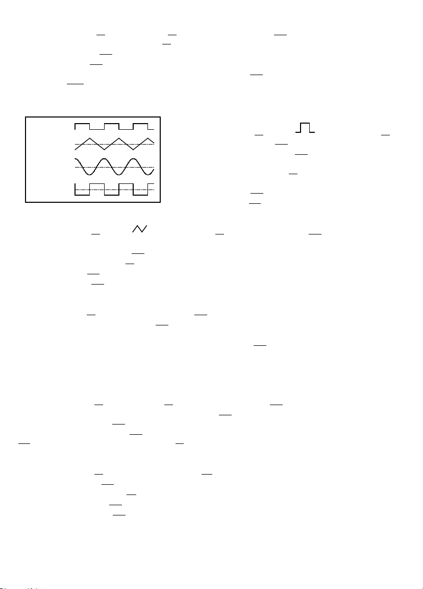
Triangle, square, and sine waves
Figure 5
TTL PULSE 0V
TRIANGLE 0V
SINE 0V
SQUARE 0V
(1) Select the Function (8) , select the Range (7), and rotate the FREQUENCY (13) knob to set the required
frequency (read output in display window (4) ).
(2) Connect the Output (22) terminal to the oscilloscope for observing the waveform signal.
(3) Rotate the AMPL (12) knob to control the waveform amplitude.
(4) If attenuation of the output signal is required, pull out the AMPL (12) knob to obtain 20dB attenuation or press
the ATT -20dB (12a) button for additional 20dB attenuation..
(5) The phase-relation of Output waveform and TTL output is shown in Figure 5 below:
Pulse wave generation
(1) Press the Function (8) button ( ), select the Range (7),
and rotate the FREQUENCY (13) knob to set the frequency.
(2) Connect the OUTPUT terminal (22) to the oscilloscope for
observing the output signal.
(3) Pull out and rotate the Duty (9) knob to adjust the width of
pulse waveform.
(4) Adjust the AMPL (12) knob to control the pulse amplitude.
(5) Pull out the AMPL (12) knob to attenuate the output signal by 20dB.
Ramp wave generation
(1) Press the Function (8) button ( ) , select the Range (7) , rotate the FREQUENCY (13) knob to set the
frequency.
(2) Connect the OUTPUT terminal (22) to the oscilloscope for observing the output signal.
(3) Pull out and rotate the Duty (9) knob to adjust the slope of ramp waveform.
(4) Adjust the AMPL (12) knob to control output amplitude of ramp waveform.
(5) Pull out the AMPL (12) knob to attenuate the output signal by 20dB.
TTL/CMOS signal output
(1) Select the Range (7) , and rotate the FREQUENCY (13) knob to set the frequency.
(2) Connect BNC connector of TTL/CMOS (20) to oscilloscope to observe the output signal.
(3) The output is a square waveform fixed at TTL level, suitable for general TTL integrated circuits.
(4) If a square waveform of CMOS level is required, pull out the CMOS (10) knob and adjust to required voltage
levels.
Variation of external voltage-controlled frequency (VCF) (FG3C-UA only)
This mode of operation allows the user to adjust the frequency of the Function Generator with an external DC
control Voltage.
(1) Select the Function (8), select the Range (7), and rotate the FREQUENCY (13) knob to set the required frequency.
(2) Connect external control voltage (0 ± 10VDC) to the VCF (21) terminal via a suitable lead, and observe the signal
generated from the Output (22) BNC terminal.
(3) Other adjustments; the AMPL (12) knob can change the amplitude of signal, or attenuate the signal; the Offset
(11) knob is for DC level changes, rotate the Duty (8) knob to change the output ratio of pulse or ramp waveform etc..
Sweep (internal) (FG3C-UA only)
(1) Select the Function (8) button and select the Range (7).
(2) Connect the OUTPUT (22) terminal to the oscilloscope channel 1 for observing the OUTPUT signal.
(3) Connect the rear panel GCV (23 ) terminal to the oscilloscope channel 2 for observing sweep control signal.
(4) Rotate the FREQUENCY (13) knob to determine the upper output sweep frequency.
(5) Pull out the FREQUENCY (13) knob to activate sweep operation.
7
Page 14

(6) Rotate the SWEEP TIME (14) knob and monitor channel 2 to set sweep time (oscilloscope signal period is sweep
repetition rate)
(7) Rotate the SWEEP RATE (16) knob and monitor channel 2 to set sweep span (oscilloscope signal amplitude is the
minimum frequency (lowest point) to maximum frequency (highest point).
(8) The sweep function is linear with the SWEEP TIME (14) knob pushed in and logarithmic when pulled out.
Note: The sweep width can only be adjusted during the sweep cycle and it cannot be stopped.
Sweep (external) (FG3C-UA only)
(1) Select the Function (8) button and select the Range (7).
(2) Connect the OUTPUT (22) terminal to the oscilloscope channel 1 for observing the OUTPUT signal.
(3) Connect the rear panel GCV (23) terminal to the oscilloscope channel 2 for observing sweep control signal.
(4) Connect a second function generator to the VCF/MOD (21) terminal for the sweep control signal.
(5) Disable the MOD EXT (17) button – LED off.
(6) Rotate the FREQUENCY (13) knob to determine the upper output sweep frequency.
(7) Pull out the FREQUENCY (13) knob to activate sweep operation.
(8) Enable the MOD EXT (17) button – LED on.
(9) The external sweep signal should go from 0 Vpp to a maximum of +10 Vpp.
0 Vpp is the frequency set in step (3).
+1 Vpp is approximately 0.1 times frequency set in step (3).
+5 Vpp is approximately 0.5 times frequency set in step (3).
+10 Vpp is approximately 0.01 times frequency set in step (3).
This method of sweeping goes from high to low.
Example: Sweep from 10 kHz to 1 kHz at a 2 kHz rate.
Set the
Set the external signal for a ramp of 2 kHz from 0 to +1 Vpp
The FG3C-UA output signal amplitude is set by the FG3C-UA amplitude controls.
Note: The sweep width can only be adjusted during the sweep cycle and it cannot be stopped.
AM/FM Modulation (internal) (FG3C-UA only)
(1) Select the Function (8), select the Range (7), rotate the FREQUENCY (13) knob to set required frequency.
(2) Connect OUTPUT terminal (22) to the oscilloscope for observing the output signal.
(3) For the FM modulation mode, press the MOD ON (15) button and pull out the MOD/DEPTH (16) knob.
(4) For the AM modulation mode, press the MOD ON (15) button and push in the MOD/DEPTH (16) knob.
(5) Adjust the MOD/DEPTH (16) knob to achieve required modulation ratio.
FREQUENCY (13) knob to 10 kHz on FG3C-UA display.
AM/FM Modulation (external) (FG3C-UA only)
(1) Select the Function (8), select the Range (7), rotate the FREQUENCY (13) knob to set required frequency.
(2) Connect OUTPUT terminal (22) to the oscilloscope for observing the output signal.
(3) Connect external modulating signal to the VCF/MOD (21) input (< 10Vpp)
(4) Press the MOD EXT (17) button to use the external modulation signal.
(5) For the FM modulation mode, press the MOD ON (15) button and pull out the MOD/DEPTH (16) knob.
(6) For the AM modulation mode, press the MOD ON (15) button and push in the MOD/DEPTH (16) knob.
(7) Adjust the MOD/DEPTH (16) knob and external signal to achieve required modulation ratio and frequency.
PRECAUTION ITEMS
(1) The DC OFFSET (11) knob, will provide a DC level voltage of ±10V (no load) or ± 5V (50 Ω load). However, the
signal amplitude plus the DC level, is limited to ±20V (no load) or ± 10V (50 Ω load). In case of over voltage,
clipping will appear as shown in Figure 6.
(2) The main OUTPUT terminal is calibrated into a 50 Ω load. This indicates that the signal source impedance is 50 Ω. The
OUTPUT terminal may be connected to any circuit input impedance, but output the voltage and terminal impedance
8
Page 15

will not be calibrated. To avoid oscillation, the OUTPUT terminal should be connected to a 50 Ω load (especially when
VAR Y T HE DU T Y O F S HOR T E R T IME S E C T ION B Y
ADJ US T ING T H E FR E QU E NC Y ADJ US T ME NT D IAL
PU LS E
(S QU AR E WAVE )
R AMP
(T R IANG L E WAVE )
T TL C MO S
UN SY ME T R IC AL
(S INE W AVE )
VAR Y T HE DU T Y O F LO NG E R T IME S E C TI ON B Y
ADJ US T ING T H E DUT Y C ON TR O LL E R
A. Ze ro DC Of fse t
With Maxi mum S ignal
B . O ffs et Limit
withou t C lippin g
C . E xc es si ve Of fse t
All e xample s :
Ou tput te rmina ted
into 50 Ω
P OS I TI VE
DC O FF S E T
NE GA T IV E
DC O FF S E T
P OS I TI VE
DC O FF S E T
P OS I TI VE
DC O FF S E T
NE GA T IV E
DC O FF S E T
NE GA T IV E
DC O FF S E T
Figure 6 Figure 7
using high frequency and square wave output), and the connecting cable should be as short as possible.
(3) When the DUTY knob is full counterclockwise, the ratio of positive state to negative state, should not be less
than 80:20. When the DUTY knob is full clockwise, the ratio of positive state to negative state, should not be
greater than 20:80. Square waves can be expanded to pulse waves, triangle waves can be expanded to ramp
waves, sine waves can be expanded to unsymmetrical sine waves. The Figure 7 shows the effect of the DUTY
control adjustment on different waveforms.
FUSE REPLACEMENT (See Figs. 2 and 4)
Preliminary: Disconnect test leads from circuit and Function Generator. Push Power Switch off and unplug the
power cord from the rear of the Function Generator.
Warning: Failure to turn off and remove power from the Function Generator before changing the mains power
fuse could result in damage to the instrument and the operator.
Fuse replacement: Remove the fuse by inserting a small flat blade screwdriver into the notch at the bottom of the
mains power connector socket. Slide the fuse holder out. Replace the fuse with one of the following:
115 VAC 50/60 Hz: T0.315A/250V fuse (5mm x 20mm), I.R. 200A – Littel Fuse p/n 218.315, or Bussmann p/n. GDC-315mA.
230 VAC 50/60 Hz: T0.160A/250V fuse (5mm x 20mm), I.R. 200A – Littel Fuse p/n 218.160, or Bussmann p/n.
GDC-160mA.
Warning: Use only an equivalent fuse to the one specified. Use of an incorrect fuse could result in serious injury or
even death.
Reassembly: Slide the fuse holder back into the fuse cavity and reconnect the power cord.
MAINTENANCE
The front panel and case can be cleaned with a mild solution of detergent and water. Apply sparingly with a soft
cloth and allow the function generator to dry completely before using. Do not use aromatic hydrocarbons or
chlorinated solvents for cleaning.
Repair
All test tools returned for warranty or non-warranty repair or for calibration should be accompanied by the
following: your name, company’s name, address, telephone number, and proof of purchase. Additionally, please
include a brief description of the problem or the service requested and include the test leads with the meter. Nonwarranty repair or replacement charges should be remitted in the form of a check, a money order, credit card with
expiration date, or a purchase order made payable to Amprobe® Test Tools.
9
Page 16

In-Warranty Repairs and Replacement – All Countries
Please read the warranty statement and check your battery before requesting repair. During the warranty period
any defective test tool can be returned to your Amprobe® Test Tools distributor for an exchange for the same or
like product. Please check the “Where to Buy” section on www.amprobe.com for a list of distributors near you.
Additionally, in the United States and Canada In-Warranty repair and replacement units can also be sent to a
Amprobe® Test Tools Service Center (see address below).
Non-Warranty Repairs and Replacement – US and Canada
Non-warranty repairs in the United States and Canada should be sent to a Amprobe® Test Tools Service Center. Call
Amprobe® Test Tools or inquire at your point of purchase for current repair and replacement rates.
In USA In Canada
Amprobe Test Tools Amprobe Test Tools
Everett, WA 98203 Mississauga, ON L4Z 1X9
Tel: 877-AMPROBE (267-7623) Tel: 905-890-7600
Non-Warranty Repairs and Replacement – Europe
European non-warranty units can be replaced by your Amprobe® Test Tools distributor for a nominal charge.
Please check the “Where to Buy” section on www.amprobe.com for a list of distributors near you.
European Correspondence Address*
Amprobe® Test Tools Europe
P.O. Box 1186
5602 BD Eindhoven
The Netherlands
*(Correspondence only – no repair or replacement available from this address. European customers please contact
your distributor.)
SPECIFICATIONS
1. Main FG2C-UA FG3C-UA
Frequency Range 0.3 Hz to 3 MHz (7 Range) 0.3 Hz to 3 MHz (7 Range)
Amplitude 10Vpp (into 50
Ω load) (typ) 10Vpp (into 50 Ω load) (typ)
Impedance 50 Ω ±10% 50 Ω ±10%
Attenuator -20dB ±1dB x 2 -20dB ±1dB x 2
DC Offset <-5V to > +5V (into 50Ω load) <-5V to > +5V (into 50 Ω load)
Duty Cycle Control 80%:20%:80% to 1MHz
80%:20%:80% to 1MHz Continuously Continuously variable
variable
LED Display N/A 6 digits; 7.6mm (0.3 in) high
Range Accuracy ±5% +1 Hz (at 3.0 position) N/A
2. Sine Wave
Distortion
≤1 %, 0.3 Hz to 200 kHz ≤1 %, 0.3 Hz to 200 kHz
35dB below fundamental (typ.) 35dB below fundamental (typ.)
(Specification applied from MAX. to
1/10 level)
Flatness < 0.3dB, 0.3 Hz to 300 kHz < 0.3dB, 0.3 Hz to 300 kHz
< 0.5dB, 300 kHz to 3 MHz < 0.5dB, 300 kHz to 3 MHz
3.Triangle Wave
Linear
≥ 98 %, 0.3 Hz to 100 kHz ≥ 98 %, 0.3 Hz to 100 kHz
≥ 95 %, 100 kHz to 3 MHz ≥ 95 %, 100 kHz to 3 MHz
4. Square Wave
Symmetry ± 2%, 0.3 Hz to 100 kHz ± 2%, 0.3 Hz to 100 kHz
Rise or Fall Time
≤ 100ns at maximum output. ≤ 100ns at maximum output.
(into 50 Ω load) (into 50 Ω load)
10
Page 17

5. CMOS Output FG2C-UA FG3C-UA
Level 4Vpp ±1Vpp to 14.5Vpp 4Vpp ±1Vpp to 14.5Vpp
± 0.5Vpp adjustable ± 0.5Vpp adjustable
Rise or Fall Time
6. TTL Output
Level
Fan Out 20 TTL load 20 TTL load
Rise or Fall Time ≤ 25ns ≤ 25ns
7. VCF
Input voltage 0 to 10V ±1V(100:1) 0 to 10V ±1V(100:1)
Input Impedance 10k
8. GCV
Output voltage N/A 0 to 2VDC
9. Sweep Operation
Sweep/Manual N/A Switch selector
Sweep Width N/A 100:1 ratio max. Varies with
Sweep Time N/A 0.5 Sec to 30 Sec adjustable
Sweep/Mode N/A Lin./Log. switch selector
10. Amplitude Modulation
Depth N/A 0 to 100%
MODulation Frequency N/A 400 Hz(INT), DC to 1 MHz (EXT)
Carrier BW N/A 100 Hz to 3 MHz (-3dB)
EXT Sensitivity N/A
11. Frequency Modulation
Deviation N/A 0 to ±5%
Modulation Frequency N/A 400Hz (INT), DC to 20 kHz (EXT)
EXT Sensitivity N/A
12. Frequency Counter
Int./Ext. N/A Switch selector
Range N/A 0.3 Hz to 3 MHz (5 Hz to 150 MHz EXT)
Accuracy N/A Time base accuracy ±1 count
Time base warm up N/A ±20 ppm (23°C ± 5°C) after 30 minutes
Resolution N/A The maximum resolution is 10 nHz for
Input Impedance N/A 1MΩ/150pf
Sensitivity N/A ≤ 35 mVrms (5Hz to 100MHz)
≤ 45 mVrms (100MHz to150MHz)
13.General
LED Display N/A 6 digits; 7.6mm (.3 in) high
Power Source 115, 230VAC ±15%, 50/60Hz 115, 230VAC ±15%, 50/60Hz
Operation Environment Indoor use, Altitude up to 2000m.
Ambient Temperature 0°C to 40°C, Relative Humidity 80%(maximum).
Storage Temperature & Humidity -10 °C to 70°C @ 70% R.H.(maximum).
Accessories 1 each BNC to alligator clip coaxial lead, 2 each each BNC to
Dimension 243(w) x 93(H) x 292(D) mm
Weight Approx. 2.0 kgs. Approx. 2.2 kgs.
≤ 120ns ≤ 120ns
≥ 3Vpp ≥ 3Vpp
Ω ±10% 10k Ω ±10%
FREQUENCY setting and RANGE
selected
≤10Vpp for 100 % modulation
≤10Vpp for 10% modulation
1Hz and 1 kHz for 100MHz
alligator clip Instruction Manual, Spare Fuse coaxial lead, Instruction
Manual, Spare Fuse
11
Page 18

Safety: Meets EN61010-1
EMC : This product complies with requirements of the following European Community Directives:
89/336/EEC (Electromagnetic Compatibility) and 73/23/EEC (Low Voltage) as amended by 93/68/
EEC (CE Marking). However, electrical noise or intense electromagnetic fields in the vicinity of
the equipment may disturb the measurement circuit. Measuring instruments will also respond to
unwanted signals that may be present within the measurement circuit. Users should exercise care
and take appropriate precautions to avoid misleading results when making measurements in the
presence of electronic interference.
12
Page 19

Deutsch
INHALT
Seite
ZERTIFIZIERUNGEN UND VORSICHTSMAßNAHMEN ........................................13
GEBRAUCHSVORBEREITUNG – AUSPACKEN .....................................................14
EINLEITUNG ........................................................................................................14
VERGLEICH DER FUNKTIONEN ...........................................................................14
BESCHREIBUNG DER BEDIENELEMENTE ............................................................17
GEBRAUCHSANLEITUNG .................................................................................... 18
VORSICHTSMASSNAHMEN ................................................................................21
SICHERUNGSWECHSEL (SIEHE ABBILDUNGEN 2 UND 4) .................................. 21
WARTUNG & REPARATUR .................................................................................. 21
SPEZIFIKATIONEN ...............................................................................................22
ZERTIFIZIERUNGEN UND VORSICHTSMAßNAHMEN
Dieses Gerät ist EN61010-1 zerifiziert. Alle Eingänge sind gegen dauerhafte Überbelastung geschützt, bis
zur Grenze welche je Funktion in den Spezifikationen angegeben oder auf dem Gerät markiert ist (Siehe
Spezifikationen). Überschreiten Sie niemals diese Grenzen. Prüfen Sie Ihren Funktionsgenerator, Meßkabel und
Zubehör vor jeder Messung. Im Problemfall (gebrochene oder beschädigte Meßkabel, gerissenes Gehäuse, keine
Anzeige), Gerät nicht verwenden. Vermeiden Sie, beim Vornehmen einer Messung, jeden Kontakt mit Erdpotential.
Berühren Sie keine Metallteile, Leiter, usw. Isolieren Sie sich gegenüber Erde (Kleidung, Schuhe, Teppich).
Verwenden Sie das Gerät nicht in einer explosiven Umgebung (entflammbare Gase, Dampf, Staub). Verwenden Sie
dieses, oder andere Meßgeräte nicht ohne entsprechende Ausbildung.
GEFAHR Hohe Spannung
ACHTUNG Anleitung lesen
Schutzleiteransschluß
Gehäuseanschluß
Übereinstimmung mit EU-Richtlinien
13
WARNUNG: Um elektrischen Schlag zu
vermeiden, Schutzleiter des Stromkabels mit
Erde verbinden.
ACHTUNG: Um Schaden am Gerät zu
vermeiden, nicht bei über 40° Messungen
vornehmen.
ACHTUNG:Um Schaden am Gerät zu
vermeiden, nicht mehr als 15V DC am VCF
Eingang anlegen.
ACHTUNG:Um Schaden am Gerät zu
vermeiden, nicht mehr als 150V AC am
Frequenzzähler Eingang anlegen (nur FG3CUA).
ACHTUNG: Um Schaden am Gerät zu
vermeiden, nicht mehr als 10Vss während EXT
Modulation anlegen (nur FG3C-UA)
Page 20

GEBRAUCHSVORBEREITUNG – AUSPACKEN
Die Verpackung sollte Folgendes enthalten: den Funktionsgenerator, eine 1 m lange Messleitung (BNC-auf-MiniKrokodilklemme), ein 115-V-Stromkabel, ein 230-V-Stromkabel, eine Ersatzsicherung für 115-V-Betrieb, eine
Ersatzsicherung für 230-V-Betrieb sowie dieses Hansbuch. Sollte ein Teil fehlen oder beschädigt sein, bringen Sie das
Gerät zur Kaufstelle zurück fur einen Umtausch.
EINLEITUNG
Die Funktionsgeneratoren FG2C-UA und FG3C-UA sind stabile Instrumente mit wenig Verzerrung, welche Sinus, Dreieck- und Rechteckwellenformen bis zu 3 MHz erzeugen. Das FG2C-UA hat Kontrollen für Amplitude, DC
Komponente und Tastverhältnis. Ausgänge sind Hauptausgang (50 Ω) und Logic-Ausgang (TTL oder CMOS). Das
FG3C-UA hat die gleichen Eigenschaften, plus interner Wobbel (Log/Linear), Modulation (AM/FM), externer VCF/
MOD, Zählereingang und GCV (Spannung proportional zur Frequenz) Ausgang. Der Zähler kann zum Zählen einer
externen Frequenz bis zu 150 MHz verwendet werden.
VERGLEICH DER FUNKTIONEN
FUNKTION / MODELL FG2C-UA FG3C-UA
AM/FM Modulation na X
Wobbel Kontrolle na X
Zählereingang na X
GCV Ausgang na X
TTL/CMOS Ausgang X X
VCF Eingang X X
Tastverhältnis Kontrolle X X
14
Page 21

Fig. 1 FG2C-UA Frontansicht
Fig. 2 FG2C-UA Rücksite
15
Page 22

P O W E R
M O
D
Fig. 3 FG3C-UA Frontansicht
Fig. 4 FG3C-UA Rücksite
16
Page 23

BESCHREIBUNG DER BEDIENELEMENTE
FRONTPLATTE
1. Ein/Aus-Schalter
Schaltet den FG2C-UA/FG3C-UA ein oder aus.
2. Torzeit-Anzeige (FG3C-UA)
Das Torintervall des internen Zählers ist 0.01 Sekunde.
2a. Torzeitwahl (FG3C-UA)
Drücken Sie diese Taste zum Ändern der Torzeit in der EXTernen Zählerbetriebsart. 0.01s, 0.1s, 1s, oder 10s
stehen zur Wahl.
3. Überlastanzeige (FG3C-UA)
Diese Anzeige leuchtet in der externen Zähler-Betriebsart wenn die Eingangsfrequenz den gewählten Bereich
überschreitet.
4. Zähleranzeige (FG3C-UA)
Zeigt die externe Frequenz auf einer 6-Digit Anzeige und die interne Frequenz auf einer 5-Digit Anzeige.
5. Frequenzanzeige (FG3C-UA)
Zeigt den Multiplikator der anstehenden Frequenz.
6. Torzeitanzeige (FG3C-UA)
Leuchtet kurz auf beim Beginn eines jeden Torintervalls.
7. Wahl des Frequenzbereiches
Wählen Sie den gewünschten Frequenzbereich durch Drücken der betreffenden Taste wie in Tabelle 1
angegeben.
Tabelle 1 Taste Frequenzbereich Taste Frequenzbereich
1 0.3Hz bis 3Hz 10k 3kHz bis 30kHz
10 3Hz bis 30Hz 100k 30kHz bis 300kHz
100 30Hz bis 300Hz 1M 300kHz bis 3MHz
1k 300Hz bis 3kHz
8. Funktionswahl
Eine der drei Tasten drücken um die gewünschte Wellenform zu wählen.
9. Taktverhältnis
Ziehen und drehen Sie diesen Knopf zum Einstellen des Taktverhältnisses.
10. TTL/CMOS Wahl
Bei eigedrücktem Knopf steht ein TTL kompatibles Signal am BNC Ausgang
den Knopf zum Einstellen eines CMOS kompatiblen Signals (5 -15Vss) am BNC Ausgang (20).
11. DC Offset Kontrolle
Ziehen und drehen Sie diesen Knopf zum Einstellen eines DC Offsets, zwischen +10V und -10V. Nach
rechts drehen zur Wahleiner positiven DC Komponente; nach links drehen zur Wahl einer negativen DC
Komponente.
12. Einstellen der Ausgangsamplitude und Abschwächung des Signals
Nach rechts drehen für einen MAX Ausgang und nach links drehen für einen MIN Ausgang. Knopf ziehen für
eine zusätzliche Abschwächung des Ausgangssignals von 20dB.
12a. 20dB Abschwächung
Diese Taste drücken zu einer weiteren Abschwächung des Ausgangssignals von 20dB .
13 FREQ/SWEEP Frequenz/Wobbel Wahl und Einstellung der Frequenz (SWEEP FG3C-UA)
(Sweep On/Off – Wobbel Ein/Aus): Knopf rechts drehen für eine MAX Frequenz und links drehen für eine
MIN Frequenz. (Knopf-Weiser im Skalenbereich der Frontplatte halten). Knopf ziehen zum Starten der
automatischen Wobbelfunktion. Die obere Frequenzgrenze wird durch die Stellung des Knopfes bestimmt.
(20) an. Ziehen und drehen Sie
17
Page 24

14 Wobbel Zeit (FG3C-UA)
Kontrolle und LIN/LOG Wahl:
(1) Knopf rechts drehen um Wobbelzeit nach MAX einzustellen und nach links drehen um Wobbeleit nach
MIN einzustellen.
(2) Knopf drücken um lineares Wobbeln einzustellen und Knopf ziehen um logarithmisches Wobbeln zu
wählen.
15. MOD Ein/Aus Wahl (FG3C-UA)
Knopf einmal drücken; LED leuchtet und der Ausgang wird durch ein internes 400Hz Sinus Signal moduliert.
Knopf erneut drücken; die LED erlöscht und der Ausgang wird mit einem externen, am VCF/MOD (21) Eingang
anstehenden Signal moduliert.
16. MOD/DEPTH (FG3C-UA)
SWEEP RATE (Wobbelgeschwindigkeit) und AM/FM Auswahlschalter:
(1) Frequenzhub kann als Verhältnis von 0 bis 100 gesteuert werden.
(2) Modulationsverhältnis nach MAX einstellen durch Drehen des Knopfes nach rechts. Nach links drehen zum
Einstellen nach links.
(3) Select AM(amplitude modulation) mode by pushing in the knob or FM(frequency modulation) mode by
pulling out the knob.
17 MOD EXT (FG3C-UA)
Wahlschalter: Knopf einmal drücken; LED leuchtet und EXTerne MODulation ist gewählt. Knopf erneut
drücken; LED erlöscht und INTerne MODulation ist gewählt.
18. INT/EXT Zählerwahl (FG3C-UA)
INT wählen für interne Zählerfunktion (zählt die Frequenz des FG3C-UA Ausganges); EXT wählen für externe
Zählerfunktion (zählt die Frequenz des am BNC Ausgang (19) anstehenden Signals.
19. MOD EXT. (FG3C-UA)
Zähler Eingang: Externe Signale zur Frequenzmessung hier anschliessen.
20. TTL/CMOS Ausgang
TTL/CMOS kompatibles Signal.
21. VCF/MOD
Spannungseingang zur Kontrolle der Frequenz oder zur Spannungsmodulation.
22. Hauptausgang
Der Ausgang ist für eine 50
23. GCV Ausgang (FG3C-UA)
Ausgang einer Frequenz-proportionalen Gleichspannung.
24. 115/230 Schalter:
Zum Anpassen des Gerätes an die Netzspannung.
Ω Last kalibriert.
GEBRAUCHSANLEITUNG
Im folgenden sind die wichtigsten Vorgänge und Einstellungen beschrieben zur Nutzung der verschiedenen
Funktionen des Gerätes. Die beste Weise um die Wellenformen zu betrachten, ist durch Anschließen des
Funktionsgenerators an ein Oszilloskop. Folgen Sie auf der Oszilloskopanzeige den Einfluß der im folgenden
beschriebenen Einstellungen auf die Wellenform.
Erste Prüfung:
(1) Stellen Sie sicher daß die Stellung des Spannungsschalters (24) auf der Geräterückseite mit Ihrer Netzspannung
übereinstimmt. Verbinden Sie das Gerät mit der Netzspannung mittels des mitgelieferten Netkabels.
(2) Drücken sie die PWR (1) Taste, stellen Sie sicher daß alle Drehknöpfe eingedrückt sind, und drehen Sie den AMPL
(12) Knopf ganz nach links.
(3) Drehen Sie den FREQ (13) Knopf ganz nach links.
Dreieck-, Rechteck- und Sinuswellenformen
(1) Wählen Sie die gewünschte Wellenform mit der Function (8) Taste und den Bereich mit Range (7). Drehen Sie
den FREQUENCY (13) Knopf zum Einstellen der gewünschten Frequenz (wird im Anzeigefenster (4) angezeigt).
(2) Verbinden Sie den Output (22) mit dem Oszilloskop um die Wellenform zu betrachten.
18
Page 25

(3) Drehen Sie den AMPL (12) Knopf um die Amplitude der Wellenform einzustellen.
Figur 5
T TL P UL S 0V
DR E IE C K 0V
S INU S 0V
R E CH T EC K
0V
(4) Falls Abschwächung des Signals erfordert ist, ziehen Sie den AMPL (12) Knopf für eine 20dB Abschwächung oder
drücken Sie die ATT -20dB (12a) Taste für eine zusätzliche 20dB Abschwächung.
(5) Die Wellenformen am Haupt- und am TTL-Ausgang sind in Figur 5 angezeigt.
Rechteck-Wellenform
(1) Drücken Sie die Function (8) ( ),Taste, wählen Sie den Bereich
mit Range (7), und drehen Sie den FREQUENCY (13) Knopf zum
Einstellen der Frequenz.
(2) Verbinden Sie den Ausgang OUTPUT (22) mit dem Oszilloskop zur
Betrachtung der Wellenform.
(3) Ziehen und drehen Sie den Duty (9) Knopf zum Einstellen der
Impulsbreite.
(4) Drehen Sie den AMPL (12) Knopf zum Einstellen der
Impulsamplitude.
(5) Ziehen Sie den AMPL (12) Knopf für eine 20dB Abschwächung.
Dreieck-Wellenform
(1) Drücken Sie die Function (8) ( ) Taste, wählen Sie den Bereich mit Range (7), und drehen Sie den
FREQUENCY (13) Knopf zum Einstellen der Frequenz.
(2) Verbinden Sie den Ausgang OUTPUT (22) mit dem Oszilloskop zur Betrachtung der Wellenform.
(3) Ziehen und drehen Sie den Duty (9) Knopf zum Einstellen der Impulsrampe.
(4) Drehen Sie den AMPL (12) Knopf zum Einstellen der Impulsamplitude.
(5) Ziehen Sie den AMPL (12) Knopf für eine 20dB Abschwächung.
TTL/CMOS Ausgang
(1) Wählen Sie den Bereich mit Range (7), und drehen Sie den FREQUENCY (13) Knopf zum Einstellen der Frequenz.
(2) Verbinden Sei den TTL/CMOS (20) Ausgang mit dem Oszilloskop zum Betrachten der Wellenform.
(3) Der Ausgang ist ein TTL-Signal, für allgemeine TTL integrierte Schaltungen verwendbar.
(4) Für ein CMOS Signal, ziehen und drehen Sie den CMOS (10) Knopf um den gewünschten Signalpegel
einzustellen.
Variation spannungsgesteuerter Frequenz (VCF) (nur FG3C-UA)
Diese Betriebsart erlaubt die Einstellung der Frequenz mit einer extern angelegten DC Spannung.
(1) Wählen Sie die Wellenform mit Function (8) und den Bereich mit Range (7). Drehen Sie den FREQUENCY (13)
Knopf um die gewünschte Frequenz einzustellen.
(2) Legen Sie eine externe Spannung (0±10VDC) an den VCF (21) Eingang und beobachten Sie das Signal am
Ausgang (22).
(3) Nehmen Sie andere Einstellungen vor – mittels AMPL (12) Knopf zum Einstellen der Amplitude, schwächen Sie
das Signal ab, drehen Sie den Offset (11) Knopf zum Einstellen einer DC Komponente, drehen Sie den Duty (8)
Knopf zum Ändern des Taktverhältnisses, usw.
Sweep-Funktion (intern) (nur FG3C-UA)
(1) Die Funktionstaste (8) auswählen und dann den Bereich (7) auswählen.
(2) Den AUSGANGSANSCHLUSS (22) an den Oszilloskopkanal 1 anschließen, um das AUSGANGSSIGNAL zu
beobachten.
(3) Den rückseitigen GCV-Anschluss (23) an den Oszilloskopkanal 2 anschließen, um das Sweep-Steuersignal zu
beobachten.
(4) Den FREQUENZKNOPF (13) drehen, um die obere Ausgangswobbelfrequenz zu bestimmen.
(5) Den FREQUENZKNOPF (13) herausziehen, um die Sweep-Funktion zu aktivieren.
19
Page 26

(6) Den WOBBELZEITKNOPF (14) drehen und Kanal 2 überwachen, um die Wobbelzeit festzulegen
(Oszilloskopsignalperiode entspricht Wobbelwiederholgeschwindigkeit).
(7) Den WOBBELGESCHWINDIGKEITSKNOPF (16) drehen und Kanal 2 überwachen, um die Wobbelbandbreite
festzulegen (Oszilloskopsignalamplitude entspricht Mindestfrequenz (niedrigster Punkt) bis Höchstfrequenz
(höchster Punkt)).
(8) Die Sweep-Funktion ist linear, wenn der WOBBELZEITKNOPF (14) eingedrückt ist, und logarithmisch, wenn er
herausgezogen ist.
Hinweis: Der Frequenzhub kann nur während des Frequenzzyklus eingestellt und nicht gestoppt werden.
Sweep-Funktion (extern) (nur FG3C-UA)
(1) Die Funktionstaste (8) auswählen und dann den Bereich (7) auswählen.
(2) Den AUSGANGSANSCHLUSS (22) an den Oszilloskopkanal 1 anschließen, um das AUSGANGSSIGNAL zu
beobachten.
(3) Den rückseitigen GCV-Anschluss (23) an den Oszilloskopkanal 2 anschließen, um das Sweep-Steuersignal zu
beobachten.
(4) Einen zweiten Funktionsgenerator für das Sweep-Steuersignal an den VCF/MOD-Anschluss (21) anschließen.
(5) Die MOD EXT-Taste (17) deaktivieren – LED aus.
(6) Den FREQUENZKNOPF (13) drehen, um die obere Ausgangswobbelfrequenz zu bestimmen.
(7) Den FREQUENZKNOPF (13) herausziehen, um die Sweep-Funktion zu aktivieren.
(8) Die MOD EXT-Taste (17) aktivieren – LED ein.
(9) Das externe Sweep-Signal sollte von 0 Vpp bis zu maximal +10 Vpp laufen.
0 Vpp ist die in Schritt (3) festgelegte Frequenz.
+1 Vpp entspricht ungefähr 0,1 Mal der in Schritt (3) festgelegten Frequenz.
+5 Vpp entspricht ungefähr 0,5 Mal der in Schritt (3) festgelegten Frequenz.
+10 Vpp entspricht ungefähr 0,01 Mal der in Schritt (3) festgelegten Frequenz.
Diese Sweep-Methode läuft von hoch zu niedrig.
Beispiel: Sweep-Funktion von 10 kHz zu 1 kHz mit einer Rate von 2 kHz.
Den
Das externe Signal für eine Rampe von 2 kHz von 0 bis +1 Vpp einstellen.
Die FG3C-UA-Ausgangssignalamplitude wird durch die FG3C-UA-Amplitudensteuerung eingestellt.
Hinweis: Der Frequenzhub kann nur während des Frequenzzyklus eingestellt und nicht gestoppt werden.
FREQUENZKNOPF (13) auf der FG3C-UA-Anzeige auf 10 kHz einstellen.
AM/FM-Modulation (intern) (nur FG3C-UA)
(1) Wählen Sie die Wellenform mit einer Function (8) Taste und den Bereich mit Range (7). Drehen sie den
FREQUENCY (13) Knopf zum Einstellen der Frequenz.
(2) Verbinden Sie den Ausgang (22) mit dem Oszilloskop zum Beobachten des Ausgangssignals.
(3) Drücken Sie die MOD ON (15) Taste zur Wahl der FM Betriebsart und ziehen Sie den MOD/DEPTH (16) Knopf.
(4) Drücken Sie die MOD ON (15) Taste zur Wahl der AM Betriebsart und drücken Sie den MOD/DEPTH (16) Knopf.
(5) Drehen Sie den MOD/DEPTH (16) Knopf für das gewünschte Modulationsverhältnis.
AM/FM-Modulation (extern) (nur FG3C-UA)
(1) Die Funktionstaste (8) auswählen, den Bereich (7) auswählen und den FREQUENZKNOPF (13) drehen, um die
erforderliche Frequenz einzustellen.
(2) Den AUSGANGSANSCHLUSS (22) an das Oszilloskop anschließen, um das Ausgangssignal zu beobachten.
(3) Das externe Modulationssignal an den VCF/MOD-Eingang (21) anschließen (< 10 Vpp).
(4) Die MOD EXT-Taste (17) drücken, um das externe Modulationssignal zu verwenden.
(5) Für den FM-Modulationsmodus die MOD ON-Taste (15) drücken und den MOD/DEPTH-Knopf (16) herausziehen.
(6) Für den AM-Modulationsmodus die MOD ON-Taste (15) drücken und den MOD/DEPTH-Knopf (16) eindrücken.
(7) Den MOD/DEPTH-Knopf (16) und das externe Signal justieren, um den erforderlichen Modulationsgrad und die
erforderliche Modulationsfrequenz zu erhalten.
20
Page 27

VORSICHTSMASSNAHMEN
Figur 6 Figur 7
A. k ein DC O ffs et
mit Max S ignal
B . O ffs etg ren ze
ohn e B e sc hnitt
C . Zu vie l O ffs et
Alle B eis pie le:
Aus gang in
50 o hm
P OS I TI VE R
DC O FF S E T
NE GA T IV ER
DC O FF S E T
P OS I TI VE R
DC O FF S E T
P OS I TI VE R
DC O FF S E T
NE GA T IV ER
DC O FF S E T
IMP UL S B R EI TE ÄN DE R N D UR C H
FR E Q UE NZR E G EL UN G
IMP UL S
(R E C HT E CK )
R AMP E
(S ÄG EZAH N)
T TL C MO S
UN SY MM ET IS C HE
(S INU S WE LL E )
B R E ITE DE S LÄN GE R E N SE G ME NT E S ÄND E RN
DU R CH T AK TV ER H ÄLT NIS R E G E LU NG
(1) Der DC OFFSET (11) Knopf dient zum Einstellen eines DC Spannungspegels von ±10V (ohne Last) oder ±5V (mit
50Ω Last). Die Signalamplitude, inklusiv DC Spannung, ist jedoch begrenzt auf ±20V (ohne Last) oder ±10V (mit
50 Ω Last). Bei überschrittener Grenze wird das Signal beschnitten, wie in Figur 6 gezeigt.
(2) Der Hauptausgang ist kalibriert für eine 50 Ω Last. Die Impedanz der Signalquelle ist ebenfalls 50 Ω. Der
Ausgang kann mit irgendwelcher Last verbunden werden, Ausgangsspannung und Impedanz sind dann jedoch
nicht kalibriert. Um Oszillation zu vermeiden, verbinden Sie den Ausgang mit einer 50 Ω Last (speziell bei hoher
Frequenz und Rechtecksignal). Das Verbindungskabel sollte möglichst kurz sein.
(3) Wenn der DUTY Knopf ganz nach links gedreht ist, soll das Verhältnis zwischen positivem und negativem Teil
nicht weniger als 80:20 sein. Wenn der DUTY Knopf ganz nach rechts gedreht ist, soll das Verhältnis zwischen
positivem und negativem Teil nicht höher als 20:80 sein. Rechtecksignale können in Impulssignale umgeformt
werden, Dreiecksignal in Sägezahnsignale, und Sinuswellenformen in unsymmetrische Sinussignale. The Figur 7
zeigt den Einfluss der DUTY Kontrolle auf verschiedene Wellenformen.
SICHERUNGSWECHSEL (SIEHE ABBILDUNGEN 2 UND 4)
Vorbereitung: Trennen Sie die Meßkabel vom Meßkreis und vom Funktionsgenerator. Drücken Sie den Ein/Aus
Schalter und trennen Sie das Netzkabel vom Gerät.
Warnung: Nicht-Abschalten des Gerätes und Nicht-Entfernen des Netzkabels vor dem Sicherungswechsel kann
zu Schaden am Gerät und Verletzungen führen.
Sicherungswechsel: Alte Sicherung entfernen durch Einbringen der flachen Spitze eines kleinen Schraubenziehers
in die Öffnung am Sockel des Netzspannungssteckers. Gleiten Sie den Sicherungshalter heraus. Ersetzen Sie die
Sicherung wie folgt:
115 VAC 50/60 Hz: T0.315A/250V Sicherung (5mm x 20mm), I.R. 200A – Littel Fuse p/n 218.315, oder Bussmann p/n.
GDC-315mA.
230 VAC 50/60 Hz: T0.160A/250V Sicherung (5mm x 20mm), I.R. 200A – Littel Fuse p/n 218.160, oder Bussmann p/n.
GDC-160mA.
Warnung: Nur eine equivalente Sicherung verwenden. Sonst besteht Verletzungs- oder selbst Lebensgefahr.
Zusammensetzung: Sicherungshalter zurück in Öffnung schieben und Netzkabel einstecken.
WARTUNG & REPARATUR
Sollte beim Anwenden des Gerätes ein Problem auftreten, gehen Sie wie fogt vor um die Fehlerquelle zu
bestimmen: (1) Lesen Sie die Anleitung um eventuelle Fehler bei der Bedienung festzustellen. (2) Prüfen Sie die
Testkabel auf Bruch oder intermittente Verbindung. (3) Prüfen Sie die Sicherung. Siehe Sicherungswechsel. Mit
Ausnahme des Sicherungswechsels und Wechsels der Testkabel soll eine Reparatur des Funktionsgenerators nur
durch eine anerkannte Servicestelle oder durch Fachpersonal vorgenommen werden. Das Gehäuse kann mit einer
milden Seifenlösung gereinigt werden. Sparsam mit einem weichen Tuch auftragen und Gerät vor erneutem
Einsatz gut trocknen lassen.
21
Page 28

Reparatur
Zu allen Geräten, die zur Reparatur oder Kalibrierung im Rahmen der Garantie oder außerhalb der Garantie
eingesendet werden, muss folgendes beigelegt werden: Name des Kunden, Firmenname, Adresse, Telefonnummer
und Kaufbeleg. Zusätzlich bitte eine kurze Beschreibung des Problems oder der gewünschten Wartung sowie
die Messleitungen dem Messgerät beilegen. Die Gebühren für Reparaturen außerhalb der Garantie oder für den
Ersatz von Instrumenten müssen als Scheck, Geldanweisung, Kreditkarte (Kreditkartennummer mit Ablaufdatum)
beglichen werden oder es muss ein Auftrag an Amprobe Test Tools formuliert werden.
Garantiereparaturen oder -austausch – Alle Länder
Bitte die nachfolgende Garantieerklärung lesen und die Batterie prüfen, bevor Reparaturen angefordert werden.
Während der Garantieperiode können alle defekten Geräte zum Umtausch gegen dasselbe oder ein ähnliches
Produkt an den Amprobe Test Tools-Distributor gesendet werden. Ein Verzeichnis der zuständigen Distributoren ist
im Abschnitt „Where to Buy“ (Verkaufsstellen) auf der Website www.amprobe.com zu finden.
Darüber hinaus können in den USA und in Kanada
Geräte an ein Amprobe Test Tools Service-Center (Adresse siehe weiter unten) zur Reparatur oder zum Umtausch
eingesendet werden.
Reparatur oder Austausch - ausserhalb der Garantieperiode - USA und Kanada
Für Reparaturen außerhalb der Garantie in den Vereinigten Staaten und in Kanada werden die Geräte
an ein Amprobe Test Tools Service-Center gesendet. Auskunft über die derzeit geltenden Reparatur- und
Austauschgebühren erhalten Sie von Amprobe Test Tools oder der Verkaufsstelle.
In den USA: In Kanada:
Amprobe Test Tools Amprobe Test Tools
Everett, WA 98203 Mississauga, ON L4Z 1X9
Tel: 877-AMPROBE (267-7623) Tel: 905-890-7600
Reparaturen und Austausch außerhalb der Garantie – Europa
Geräte außerhalb der Garantie können durch den zuständigen Amprobe Test Tools-Distributor gegen eine Gebühr
ersetzt werden. Ein Verzeichnis der zuständigen Distributoren ist im Abschnitt „Where to Buy“ (Verkaufsstellen)
auf der Website www.amprobe.com zu finden.
Korrespondenzanschrift für Europa*
Amprobe Test Tools Europe
P. O. Box 1186
5602 BD Eindhoven
Niederlande
*(Nur Korrespondenz – keine Reparaturen, kein Umtausch unter dieser Anschrift. Kunden in Europa wenden sich
an den zuständigen Distributor.)
SPEZIFIKATIONEN
FG2C-UA FG3C-UA
1. Hauptspezifikationen
Frequenzbereich 0.3 Hz bis 3 MHz (7 Bereiche) 0.3 Hz bis 3 MHz (7 Bereiche)
Amplitude 10 Vss (50
Ω Last) ( typisch) 10 Vss (50Ω Last)( typisch)
Impedanz 50Ω ±10% 50Ω ±10%
Abschwächung -20dB ±1dB x2 -20dB ±1dB x2
DC Offset <-5V bis >+5V (50Ω Last) <-5V bis > + 5V (50Ω Last)
Taktverhältnis 80%:20%:80% bis 1MHz 80%:20%:80% bis 1MHz kontinuierlich
kontinuierlich
22
Page 29

FG2C-UA FG3C-UA
LED Anzeige N/A 6 Digits; 7.6mm hoch
Bereichsgenauigkeit ± 5% +1 Hz (bei 3.0 Position) N/A
2. Sinuswelle
Verzerrung
THD ≤ 35dB unter Grundfrequenz, THD ≤ 35dB unter
Grundfrequenz, typisch
typisch
(Spezifikationen für MAX. bis 1/10 Bereich)
Flachheit < 0.3dB, 0.3 Hz bis 300 kHz < 0.3dB, 0.3 Hz bis 300 kHz
< 0.5dB, 300 kHz bis 3 MHz < 0.5dB, 300 kHz bis 3 MHz
3. Dreieckwelle
Linearität ≥ 98 %, 0.3 Hz bis 100 kHz ≥ 98 %, 0.3 Hz bis 100 kHz
≥ 95 %, 100 kHz bis 3 MHz ≥ 95 %, 100 kHz bis 3 MHz
4. Rechteckwelle
Symmetrie ±2%, 0.3 Hz bis 100 kHz ±2%, 0.3 Hz bis 100 kHz
Anstiegs-/Abfallzeit
(50 Ω Last) (50 Ω Last)
5. CMOS Ausgang
Spannung 4Vss ±1Vss bis 14.5Vss 4Vss ±1Vss bis 14.5Vss
±0.5Vss einstellbar ±0.5Vss einstellbar
Anstiegs-/Abfallzeit ≤ 120ns ≤ 120ns
6. TTL Ausgang
Spannung ≥ 3Vss ≥ 3Vss
Belastbarkeit 20 TTL Last 20 TTL Last
Anstiegs-/Abfallzeit ≤ 25ns ≤ 25ns
7. VCF (Spannungs-kontrollierte Frequenz)
Eingangsspannung 0 bis 10V ±1V(100:1) 0 bis 10V ±1V(100:1)
Eingangsimpedanz 10 kΩ ±10% 10 kΩ ±10%
≤1 %, 0.3 Hz bis 200 kHz ≤1 %, 0.3 Hz bis 200 kHz
≤ 100ns bei max. Ausgang ≤ 100ns bei max. Ausgang
8. GCV (Frequenz-proportionale Spannung)
Ausgangsspannung N/A Spannung ändert von 0 bis 2V gemäß eingestellter Frequenz
9. Wobbelbetriebsart
Wobbel-/Normalbetrieb N/A Schalterwahl
Frequenzhub N/A max. 100:1. Variiert mit
Wobbel Zeit N/A 0.5 Sek bis 30 Sek, einstellbar
Wobbel Modus N/A Lin./Log. durch Schalterwahl
10. Amplitudenmodulation
Modulationstiefe N/A 0 bis 100%
Modulationsfrequenz N/A 400 Hz (INT), DC bis 1 MHz (EXT)
Trägerwelle N/A 100 Hz bis 3 MHz (-3dB)
EXT Empfindlichkeit N/A ≤ 10Vss für 100 % Modulation
11. Frequenzmodulation
Abweichung N/A 0 bis ± 5%
Modulationsfrequenz N/A 400Hz (INT), DC bis 20 kHz (EXT)
EXT Empfindlichkeit N/A ≤ 10Vss für 10% Modulation
FREQUENZ-Einstellung und
BEREICH ausgewählt
23
Page 30

12. Frequenzzähler
Int./Ext. N/A Schalterwahl
Bereich N/A 0.3 Hz bis 3 MHz (5 Hz bis 150 MHz EXT)
Genauigkeit N/A Zeitbasisgenauigkeit ±1 Digit
Zeitbasis N/A ± 20ppm (23°C ± 5°C) nach 30 Min
Aufwärmung
Auflösung N/A Max. Auflösung ist 10 nHz für 1Hz
Eingangsimpedanz N/A 1M
Empfindlichkeit N/A ≤ 35mVrms (5Hz bis 100MHz)
≤ 45mVrms (100MHz bis 150MHz)
13. Allgemein
LED Anzeige N/A 6 Digits; 7.6mm hoch
Speisung 115, 230VAC ±15%, 50/60Hz 115, 230VAC ±15%, 50/60Hz
Betriebsumgebung Innenhaus, Höhe bis 2000m.
Umgebungstemperatur 0°C bis 40°C Relative Feuchte 80%(max).
Lagertemperatur & Feuchte -10 °C bis 70°C bei 70% R.F. (maximum).
Zubehör 1 1 m lange Messleitung 2 1 m lange Messleitung
(BNC-auf-Mini-Krokodilklemme), (BNC-auf-Mini-Krokodilklemme),
Anleitung Ersatzsicherung Anleitung Ersatzsicherung
Abmessungen 243(B) x 93(H) x 292(T) mm
Gewicht Approx. 2.0 kgs. Approx. 2.2 kgs.
Sicherheit: Gemäß EN61010-1
EMC : Dieses Produkt beant wort et an die Besti mmungen der folgenden EWG Richtlinien: 89/336/
EEC (Elektromagnetische Kompatibilität) und 73/23/EEC (Niedrige Spannung) geändert durch 93/68/
EEC (CE Marking). Elektrisches Rauschen und starke magnetische Felder in der direkten Umgebung
des Meßgerätes können jedoch den Meßkreis beeinflussen. Das Gerät kann auch durch Störsignale
im gemessenen Schaltkreis beeinflußt werden. Der Anwender muß Vorsichtsmaßnahmen treffen
um irreführende Meßergebnisse bei Messungen in der Umgebung von starken elektromagnetischen
Feldern zu vermeiden.
und 1 kHz für 100MHz
Ω/150pF
24
Page 31

Español
CONTENIDO
CERTIFICACIONES Y PRECAUCIONES ................................................................................................ 25
PREPARACIÓN PARA EL USO – DESEMBALAJE ................................................................................. 26
INTRODUCCIÓN .................................................................................................................................. 26
TABLA DE COMPARACIÓN DE FUNCIONES POR MODELOS ............................................................ 26
DESCRIPCIÓN DE LOS CONTROLES ................................................................................................... 29
PROCEDIMIENTOS DE USO ................................................................................................................ 30
SUSTITUCIÓN DEL FUSIBLE (Véa las figuras 2 y 4) ........................................................................... 33
MANTENIMIENTO ............................................................................................................................... 34
ESPECIFICACIONES ............................................................................................................................. 35
CERTIFICACIONES Y PRECAUCIONES
Este instrumento cumple con la norma EN61010-1. Todas las entradas están protegidas frente a situaciones
de sobrecarga continua hasta los límites de protección de entrada establecida de cada función (véase las
especificaciones). No exceda nunca estos límites o los valores límite establecidos en el propio instrumento. Antes
de cada uso, compruebe que el Generador de funciones, los conectores de ensayo y los accesorios están en
perfecto estado y no presentan signos de deterioro. Si descubriese algún problema (conectores de ensayo rotos o
dañados, carcasa agrietada, pantalla ilegible, etc.), no utilice el aparato. Asegúrese de no estar conectado a tierra
en el momento de realizar mediciones. No toque ninguna tubería metálica, enchufe, instalación, etc., que pueda
estar potencialmente conectada a tierra. Mantenga su cuerpo aislado del suelo y no toque nunca ningún cable,
conexión, punta de conector de ensayo o cualquier otro conductor sometido a tensión. No utilice el instrumento
bajo una atmósfera potencialmente explosiva (humos, vapores, polvo, gases inflamables, etc.) No utilice este ni
ningún otro instrumento de prueba sin la preparación adecuada.
PELIGRO Alta tensión
PRECAUCIÓN consulte el
Manual
Terminal de conductor de
protección
Terminal de carcasa o
armazón
Cumple con las directivas de
la Unión Europea
ADVERTENCIA: Para evitar una posible descarga
eléctrica, el cable conductor de puesta a tierra de
protección deberá estar conectado a tierra.
PRECAUCIÓN: Para evitar dañar el instrumento, no
lo utilice en lugares donde la temperatura ambiente
exceda los 40° C.
PRECAUCIÓN: Para evitar dañar el instrumento, no lo
someta a más de 15 V CC en VCF.
PRECAUCIÓN:Para evitar dañar el instrumento,
no lo someta a más de 150 V CA en el Contador de
frecuencias (sólo para el FG3C-UA).
PRECAUCIÓN:Para evitar dañar el instrumento, no
lo someta a más de 10 Vpp durante la operación de
modulación externa (sólo para el FG3C-UA).
25
Page 32

PREPARACIÓN PARA EL USO – DESEMBALAJE
El paquete de entrega deberá incluir el Generador de funciones, un conductor de prueba con mini-pinza de
conexión a un BNC de 1 metro de longitud, un cable de alimentación de 115 V, un cable de alimentación de 230
V, un fusible de repuesto para ser utilizado a 230 V y este manual. Si cualquiera de estos elementos faltase o
presentase algún defecto o daño, devuelva inmediatamente todo el paquete al lugar de compra para que le sea
entregado uno completo.
INTRODUCCIÓN
Los Generadores de funciones FG2C-UA y FG3C-UA son instrumentos estables de baja distorsión que generan
formas de ondas senoidales, triangulares y rectangulares en frecuencias que llegan a alcanzar los 3 MHz. El FG2CUA posee controles de amplitud, offset (desviación) y ciclos de trabajo. Las salidas son Principal (50 Ω) y lógica
(TTL y CMOS). El FG3C-UA tiene las mismas funciones que el anterior, a las que se añaden el barrido interno (Log/
Lineal), la modulación (AM/FM), las entradas VCF/MOD externas y de contador y la salida GCV. El contador puede
conmutarse para medir y mostrar la frecuencia de una señal externa de hasta 150 MHz..
TABLA DE COMPARACIÓN DE FUNCIONES POR MODELOS
FUNCIÓN / MODELO FG2C-UA FG3C-UA
Modulación AM/FM na X
Control de barrido na X
Entrada de CONTADOR na X
Salida GCV na X
Salida TTL/CMOS X X
Entrada VCF X X
Control de ciclos de trabajo X X
26
Page 33

Fig. 1 FG2C-UA Panel Frontal
Fig. 2 FG2C-UA Panel Posterior
27
Page 34

P O W E R
M O
D
Fig. 3 FG3C-UA Panel Frontal
Fig. 4 FG3C-UA Panel Posterior
28
Page 35

DESCRIPCIÓN DE LOS CONTROLES
PANEL FRONTAL
1. Interruptor de alimentación (POWER)
Abre y cierra el acceso de la corriente eléctrica a la fuente de alimentación del aparato.
2. Indicador de tiempo de puerta (FG3C-UA)
Indicador de intervalo de puerta (el intervalo de puerta del contador de intervalos es 0,01 s).
2a. Selector de tiempo de puerta (GATE) (FG3C-UA)
Presione este botón para cambiar el tiempo de puerta cuando esté utilizando el modo de contador externo
(EXT). Al pulsarlo, la secuencia de selección será 0,01 s, 0,1 s, 1 s, o 10 s.
3. Indicador de superación de rango (FG3C-UA)
En el modo de contador externo, este indicador se ilumina cuando la frecuencia de salida sea mayor que el
rango seleccionado.
4. Pantalla del contador (FG3C-UA)
Muestra la frecuencia externa por medio de una pantalla verde de 6 dígitos, y la frecuencia interna por medio
de una pantalla verde de 5 dígitos.
5. Indicador de frecuencia (FG3C-UA)
Indica el multiplicador del valor de la frecuencia seleccionada.
6. Indicador de tiempo de puerta (FG3C-UA)
Parpadea al principio de cada intervalo de puerta.
7. Selector de rango de frecuencias
Seleccione el rango de frecuencias deseado pulsando el botón correspondiente en el panel según se indica en
la Tabla 1.
Tabla 1 Botón Rango de frecuencias Botón Rango de frecuencias
1 0,3 Hz a 3 Hz 10 k 3 kHz a 30 kHz
10 3 Hz a 30 Hz 100 k 30 kHz a 300 kHz
100 30 Hz a 300 Hz 1 M 300 kHz a 3 MHz
1k 300 Hz a 3 kHz
8. Selector de funciones
Presione uno de los tres botones para seleccionar la forma de onda de salida que desea.
9. Función de trabajo (DUTY)
Tire del mando y gírelo para ajustar el ciclo de trabajo de la forma de onda.
10. Selector TTL/CMOS
Cuando el mando giratorio se encuentra presionado, del terminal BNC de salida
(20) saldrá una forma de onda compatible TTL. Si el mando está hacia afuera, al girarlo ajustará la salida
compatible CMOS (5 –15 Vpp) de dicho terminal.
11. Control de Offset CC (OFFSET)
Tire del mando giratorio para seleccionar cualquier nivel CC de la forma de onda entre ±10 V; gire el mando
a la derecha para seleccionar un nivel positivo de Offset CC de la forma de onda, o hacia la izquierda para
seleccionar un nivel negativo.
12. Control de amplitud de salida con función de atenuación (AMPL)
Gire el mando a la derecha para obtener una salida máxima (MAX) y hacia la izquierda para obtener una
salida mínima (MIN). Tire del mando para obtener una atenuación de salida adicional de 20 dB.
12a. Atenuación de 20 dB (ATT –20dB)
Presione este botón para reducir la salida en 20 dB.
13 Selector de frecuencia (FREQUENCY) con Activación y Desactivación del barrido (SWEEP ON/OFF)
(SWEEP FG3C-UA)
Gire el mando hacia la derecha para obtener frecuencias máximas y hacia la izquierda para frecuencias
mínimas. (Mantenga el puntero del mando dentro del rango de escalas del panel). Tire del mando giratorio
para comenzar la operación de barrido automático; el límite superior de frecuencias viene determinado por la
posición del mando.
TTL/CMOS OUTPUT
29
Page 36

14 Control de tiempo de barrido (SWEEP TIME) y Selector LIN/LOG (FG3C-UA):
(1) Gire el mando a la derecha para ajustar el tiempo de barrido al máximo (FAST), o hacia la izquierda para
ajustarlo al mínimo (SLOW).
(2) Para seleccionar el modo de barrido lineal (LIN), presione el mando giratorio; para seleccionar el modo de
barrido LOG, tire de él hacia afuera.
15. Selector de activación/desactivación de modulación (MOD ON) (FG3C-UA)
Si presiona una vez el botón, el indicador se encenderá y la salida será modulada por una onda senoidal
interna de 400 Hz; si vuelve a presionar el botón, el indicador se apagará y la salida será modulada por una
señal externa a través del conector de entrada VCF/MOD INPUT (21).
16. Profundidad de barrido (MOD/DEPTH) (FG3C-UA)
Selector de tasa de barrido (SWEEP RATE) y AM/FM:
(1) La anchura del barrido se puede controlar en una proporción de 0 a 100.
(2) Ajuste el índice de modulación girando el mando hacia la derecha para obtener un valor máximo, o hacia
la izquierda para un valor mínimo.
(3) Para seleccionar el modo
el modo FM (modulación de frecuencia), tire de él hacia afuera.
17 Selector de modulación externa (MOD EXT) (FG3C-UA):
Presione una vez el botón, el indicador se iluminará, y quedará seleccionada la modulación externa. Si vuelve
a presionar el botón, el indicador se apagará y quedará seleccionada la modulación interna.
18. Selector de contador interno/externo (COUNTER INT/EXT) (FG3C-UA)
Seleccione el modo de contador interno (cuente la frecuencia de la salida del generador FG3C-UA) o el modo
de contador externo si desea un contador independiente (señal de entrada procedente del terminal BNC
INPUT COUNTER (19)).
19. Terminal de entrada del contador (INPUT COUNTER) (FG3C-UA)
Permite la entrada de señales externas para su medición.
20. Terminal de salida TTL/CMOS (TTL/CMOS OUTPUT)
Salida de señales compatibles
21. Terminal de entrada VCF/MOD (VCF/MOD INPUT)
Conector que permite la entrada de la tensión necesaria para realizar las operaciones de VCF (frecuencia
controlada por tensión) o la modulación externa (EXT).
22. Terminal de salida principal (OUTPUT)
Salida de señal principal: la señal de salida está calibrada para una carga de 50
23. Salida GCV (GCV OUTPUT) (FG3C-UA)
Se trata de una salida de tensión CC cuyo nivel seguirá el cambio de frecuencia.
24. Selector 115/230
Este conmutador permite seleccionar la tensión de alimentación de la red.
AM (modulación de amplitud), presione el mando hacia dentro; para seleccionar
TTL/CMOS.
Ω.
PROCEDIMIENTOS DE USO
El siguiente apartado describe la configuración básica y los controles necesarios para trabajar con las funciones
de este instrumento. Uno de los mejores métodos para observar formas de ondas es conectar el generador de
funciones a un osciloscopio. Obsérvese el efecto que los distintos controles tienen sobre las formas de ondas que
aparecen en el osciloscopio cuando se siguen los siguientes pasos:
Primer paso: comprobación
(1) Asegúrese de que el selector de tensión de la red (24), situado en el panel posterior del instrumento, señala la
alimentación de red adecuada. Conecte el instrumento a la red por medio del cable que se suministra.
(2) Presione el interruptor de alimentación, POWER (1); asegúrese de que todos los mandos giratorios están
presionados hacia dentro y gire el mando AMPL (12) totalmente a la izquierda.
(3) Gire el control FREQUENCY (13) totalmente a la izquierda.
30
Page 37

Ondas triangulares, rectangulares y senoidales
Figura 5
PU LS O T T L
0V
T R IÁNG UL O
0V
S EN O 0V
R E CT ÁNG U LO
0V
(1) Seleccione la Función (8) y el Rango (7), y gire el mando FREQUENCY (13) hasta obtener la frecuencia deseada
(lea la salida en la pantalla (4)).
(2) Conecte el terminal de salida OUTPUT (22) al osciloscopio para observar la señal de la forma de onda.
(3) Gire el mando AMPL (12) para controlar la amplitud de la forma de onda.
(4) Si se hace necesario atenuar la señal de salida, tire hacia afuera del mando giratorio AMPL (12) para obtener
una atenuación de 20 dB o presione el botón ATT -20dB (12a) para lograr una atenuación adicional de 20 dB.
(5) En la figura 5 se muestra la relación fase entre forma de onda de salida y salida TTL:
Generación de ondas pulsatorias
(1) Presione el botón de Función (8) ( ), seleccione el Rango (7) y
gire el mando FREQUENCY (13) hasta fijar la frecuencia deseada.
(2) Conecte el terminal de salida OUTPUT (22) al osciloscopio para
observar la señal de salida.
(3) Tire del mando DUTY (9) y gírelo para ajustar el ancho de la onda
pulsatoria.
(4) Ajuste el mando giratorio AMPL (12) para controlar la amplitud del
pulso.
(5) Tire del mando AMPL (12) para atenuar la señal de salida en 20 dB.
Generación de ondas con forma de dientes de sierra
(1) Presione el botón de Función (8) ( ), seleccione el Rango (7) y gire el mando FREQUENCY (13) hasta fijar la
frecuencia deseada.
(2) Conecte el terminal de salida OUTPUT (22) al osciloscopio para observar la señal de salida.
(3) Tire del mando DUTY (9) y gírelo para ajustar el declive de la onda de dientes de sierra.
(4) Ajuste el mando giratorio AMPL (12) para controlar la amplitud de salida de la onda de dientes de sierra.
(5) Tire del mando AMPL (12) para atenuar la señal de salida en 20 dB.
Salida de señales TTL/CMOS
(1) Seleccione el Rango (7) y gire el mando FREQUENCY (13) hasta fijar la frecuencia deseada.
(2) Conecte el conector BNC de salida TTL/CMOS OUTPUT (20) al osciloscopio para observar la señal de salida.
(3) La salida es una forma de onda rectangular fija en el nivel TTL, adecuada para circuitos integrados TTL.
(4) Si se necesitara una forma de onda rectangular de nivel CMOS, tire hacia afuera del mando giratorio CMOS (10)
y ajústelo en los niveles de tensión requeridos.
Variación de frecuencia controlada por tensión (VCF) (sólo FG3C-UA)
Este método permite al usuario ajustar la frecuencia del Generador de funciones utilizando una tensión de control
CC externa.
(1) Seleccione el botón de Función (8), seleccione el Rango (7) y gire el mando FREQUENCY (13) hasta fijar la
frecuencia deseada.
(2) Conecte la tensión de control externa (0 ±10 VCC) al terminal VCF INPUT (21) por medio de un cable adecuado y
observe la señal generada en el terminal BNC de salida, OUTPUT (22).
(3) Otros ajustes; el mando giratorio AMPL (12) puede cambiar la amplitud de señal o atenuar la señal; el mando
OFFSET (11) permite cambiar el nivel de CC; el mando DUTY (8) hace posible cambiar el índice de salida de la onda
pulsatoria o de dientes de sierra, etc.
Barrido (interno) (sólo FG3C-UA)
(1) Seleccione el botón de Función (8) y seleccione el Rango (7).
(2) Conecte el terminal de salida OUTPUT (22) al canal 1 del osciloscopio para observar la señal de salida.
(3) Conecte el terminal GCV (23) del panel posterior al canal 2 del osciloscopio para observar la señal de control de
barrido.
31
Page 38

(4) Gire el mando FREQUENCY (13) para determinar la frecuencia de barrido de salida superior.
(5) Tire del mando FREQUENCY (13) para activar la operación de barrido.
(6) Gire el mando de tiempo de barrido SWEEP TIME (14) y monitorice el canal 2 para establecer el tiempo de
barrido (el período de la señal del osciloscopio es una frecuencia de repetición del barrido)
(7) Gire el mando SWEEP RATE (16) y monitorice el canal 2 para establecer el intervalo de barrido (la amplitud de la
señal del osciloscopio es la frecuencia mínima [punto más bajo] a la frecuencia máxima [punto más alto]).
(8) La función de barrido es lineal cuando el mando SWEEP TIME (14) está presionada, y logarítmica cuando no está
presionada.
Nota: La anchura del barrido sólo se puede ajustar durante el ciclo de barrido y no se puede detener.
Barrido (externo) (sólo FG3C-UA)
(1) Seleccione el botón de Función (8) y seleccione el Rango (7).
(2) Conecte el terminal de salida OUTPUT (22) al canal 1 del osciloscopio para observar la señal de salida.
(3) Conecte el terminal GCV (23) del panel posterior al canal 2 del osciloscopio para observar la señal de control de
barrido.
(4) Conecte otro generador de funciones al terminal VCF/MOD (21) para la señal de control del barrido.
(5) Desactive el botón MOD EXT (17) – LED apagado.
(6) Gire el mando FREQUENCY (13) para determinar la frecuencia de barrido de salida superior.
(7) Tire del mando FREQUENCY (13) para activar la operación de barrido.
(8) Active el botón MOD EXT (17) – LED encendido.
(9) La señal de barrido externa irá de 0 Vpp a un máximo de +10 Vpp.
0 Vpp es la frecuencia establecida en el paso (3).
+1 Vpp es aproximadamente 0,1 veces la frecuencia establecida en el paso (3).
+5 Vpp es aproximadamente 0,5 veces la frecuencia establecida en el paso (3).
+10 Vpp es aproximadamente 0,01 veces la frecuencia establecida en el paso (3).
Este método de barrido va de mayor a menor.
Por ejemplo: Barre de 10 kHz a 1 kHz a una frecuencia de 2 kHz.
Fije el mando
Fije la señal externa para una rampa de 2 kHz de 0 a +1 Vpp
La amplitud de la señal de salida del FG3C-UA se establece mediante los controles de amplitud de éste.
Nota: La anchura del barrido sólo se puede ajustar durante el ciclo de barrido y no se puede detener.
FREQUENCY (13) en 10 kHz en la pantalla del FG3C-UA.
Modulación AM/FM (interna) (sólo FG3C-UA)
(1) Seleccione el botón de
frecuencia deseada.
(2) Conecte el terminal de salida
(3) Para la modulacin FM, pulse el botón
(4) Para la modulacóin AM, pulse el botón
(5) Ajuste el mando giratorio
Modulación AM/FM (externa) (sólo FG3C-UA)
(1) Seleccione la Función (8), seleccione el Rango (7) y gire el mando FREQUENCY (13) para establecer la frecuencia
requerida.
(2) Conecte el terminal de salida OUTPUT (22) al osciloscopio para observar la señal de salida.
(3) Conecte la señal de modulación externa a la entrada VCF/MOD (21) (< 10Vpp)
(4) Pulse el botón MOD EXT (17) para utilizar la señal de modulación externa.
(5) Para el modo de modulación FM, pulse el botón MOD ON (15) y tire de la perilla MOD/PROF (16).
(6) Para el modo de modulación AM, pulse el botón MOD ON (15) y presione la perilla MOD/PROF (16).
(7) Ajuste el mando MOD/PROF (16) y la señal externa para lograr la proporción y la frecuencia de modulación
requeridos.
Función (8) seleccione el Rango (7) y gire el mando FREQUENCY (13) hasta fijar la
OUTPUT (22) al oscilosopio para observar la señal de salida.
MOD (15) y tire hacia afuera del mando giratorio MOD/DEPTH (16).
MOD (15) y presione hacia dentro el mando giratorio MOD/DEPTH (16).
MOD/DEPTH (16) hasta lograr el índice de modulación requerido.
32
Page 39

Elementos de precaución
Figura 6 Figura 7
A. O ffs et CC c er o
co n s eña l máxi ma
B . L ímite de Off se t
s in tr unca miento
C . O ffs et e xc es ivo
T odos lo s eje mplos :
S alida ter minada
es 50 ohmios
OF F S E T CC
P OS I TI VA
OF F S E T CC
NE GA T IV A
OF F S E T CC
P OS I TI VA
OF F S E T CC
P OS I TI VA
OF F S E T CC
NE GA T IV A
V AR Í E E L TR A B A J O D E S E C C IÓ N D E TI E M P O M Á S
C O R T O A J U S TA ND O E L D IAL DE AJ U S TE D E F R E C U E NC I A
P UL SO
(O NDA
R E CT ANG U LAR )
DIE N TE S
DE S IE R R A
(O NDA TR IAN GU LAR )
T TL C MO S
AS IMÉ T R ICA
(O NDA SE N OIDAL )
V AR Í E E L TR A B A J O D E S E C C IÓ N D E TI E M P O M Á S
L AR G O AJ U S TA ND O E L C O N TR O LA D O R D E T R A B A J O
(1) El mando giratorio OFFSET (11) ofrecerá una tensión de nivel CC de ±10 V (sin carga) o de ±5 V (con carga de 50
Ω). No obstante, la amplitud de la señal, más el nivel de CC, está limitada a ± 20 V (sin carga) o ± 10 V (con carga de
50 Ω). En caso de sobretensión, aparecerá un truncamiento como muestra la figura 6:
(2) El terminal de salida principal OUTPUT está calibrado para una carga de 50 Ω. Esto indica que la impedancia de
la fuente de la señal es 50 Ω. El terminal OUTPUT pueden estar conectado a cualquier impedancia de entrada de
circuito, pero no se calibrará la tensión de salida ni la impedancia del terminal. Para evitar oscilaciones, el terminal
OUTPUT deberá conectarse a una carga de 50 Ω – (especialmente cuando se trabaja con frecuencias altas y salidas
de onda rectangulares) y el cable de conexión deberá ser lo más corto posible.
(3) Cuando el mando giratorio DUTY está girado completamente a la izquierda, la proporción de estado positivo a
estado negativo no deberá ser menor que 80:20. Cuando el mando DUTY está girado completamente a la derecha,
la proporción de estado positivo a estado negativo no deberá ser mayor que 20:80. Las ondas rectangulares
pueden ampliarse a ondas pulsatorias; las ondas triangulares, a ondas con forma de dientes de sierra; y las ondas
senoidales, a ondas senoidales asimétricas. La figura 7 muestra el efecto del ajuste del mando DUTY en diferentes
formas de ondas.
SUSTITUCIÓN DEL FUSIBLE (Véa las figuras 2 y 4)
Previamente: Desconecte los conectores de ensayo del circuito y del Generador de funciones. Apague el interruptor
de alimentación y desconecte el cable de alimentación a la red de la parte posterior del Generador de funciones.
Advertencia: Si no se apaga el Generador de funciones y se retira el cable de alimentación del mismo antes de
cambiar el fusible, el aparato o el propio usuario pueden sufrir graves daños.
Sustitución del fusible: Extraiga el fusible insertando la punta de un destornillador de cabeza plana en la muesca
que hay al fondo del enchufe de alimentación. Extraiga el portafusible. Sustituya en fusible gastado por uno de los
siguientes:
115 V AC 50/60 Hz: Fusible T0.315 A/250 V (5 mm x 20 mm), I.R. 200A – Littel Fuse p/n 218.315 o Bussmann p/n.
GDC-315 mA.
230 V AC 50/60 Hz: Fusible T0.160 A/250 V (5 mm x 20 mm), I.R. 200A – Littel Fuse p/n 218.160 o Bussmann p/n.
GDC-160 mA.
Advertencia: Utilice exclusivamente un fusible equivalente al especificado. El uso de un fusible inadecuado podría
causar graves lesiones e incluso la muerte.
Montaje: Inserte el portafusible, con el nuevo fusible dentro, en su lugar y vuelva a conectar el cable de
alimentación.
33
Page 40

MANTENIMIENTO
Si detectase un funcionamiento incorrecto del Generador de funciones, siga los siguientes pasos para tratar de
aislar la posible causa del problema: (1) Vuelva a leer las instrucciones de funcionamiento del aparato para posibles
errores en el modo de trabajar con el mismo. (2) Inspeccione y pruebe los cables de ensayo por si hubiese alguna
conexión rota o inestable. (3) Revise y pruebe el fusible. Consulte la sección “Sustitución del fusible” más arriba en
este manual. Exceptuando la sustitución del fusible o los cables de ensayo, cualquier reparación del Generador de
funciones deberá ser llevada a cabo sólo por personal del Servicio de Asistencia Técnica Autorizado o por personal
cualificado para la reparación de este tipo de instrumentos.
Tanto el panel frontal como el bastidor del aparato pueden limpiarse con una disolución suave de detergente y
agua. Con un paño, aplique una cantidad mínima de dicha disolución y deje que el generador se seque del todo
antes de volver a utilizarlo. No utilice hidrocarburos ni disolventes tratados con cloro para esta limpieza.
Reparación
Todas las herramientas de comprobación devueltas para su calibración o reparación, cubiertas o no por la garantía,
deberán estar acompañadas por lo siguiente: su nombre, el nombre de la empresa, la dirección, el número de
teléfono y una prueba de compra. Además, incluya una breve descripción del problema o del servicio solicitado
y las puntas de prueba del medidor. Los pagos correspondientes a reparaciones o reemplazos no cubiertos por la
garantía se deben remitir a la orden de Amprobe Test Tools en forma de cheque, giro postal, pago mediante tarjeta
de crédito (incluir el número y la fecha de vencimiento) u orden de compra.
Reparaciones y reemplazos cubiertos por la garantía – Todos los países
Antes de solicitar una reparación sirvase leer la siguiente declaración de garantía y compruebe el estado de la pila.
Durante el periodo de garantía, toda herramienta de comprobación en mal estado de funcionamiento puede ser
devuelta al distribuidor de Amprobe Test Tools para cambiarla por otra igual o un producto semejante. Consulte la
sección “Dónde comprar” del sitio www.amprobe.com en Internet para obtener una lista de los distribuidores de su
zona. Además, en los Estados Unidos y Canadá las unidades para reparación y reemplazo cubiertas por la garantía
también se pueden enviar a un Centro de Servicio de Amprobe Test Tools (las direcciones se incluyen más adelante).
Reparaciones y reemplazos no cubiertos por la garantía – Estados Unidos y Canadá
Las unidades para reparaciones no cubiertas por la garantía en Estados Unidos y Canadá se deben enviar a un
Centro de Servicio de Amprobe Test Tools. Póngase en contacto con Amprobe Test Tools o con el vendedor de su
producto para solicitar información acerca de los precios vigentes para reparación y reemplazo.
En Estados Unidos En Canadá
Amprobe Test Tools Amprobe Test Tools
Everett, WA 98203 Mississauga, ON L4Z 1X9
Tel: 877-AMPROBE (267-7623) Tel: 905-890-7600
Reparaciones y reemplazos no cubiertos por la garantía – Europa
El distribuidor de Amprobe Test Tools puede reemplazar aplicando un cargo nominal las unidades vendidas en
Europa no cubiertas por la garantía. Consulte la sección “Dónde comprar” del sitio www.amprobe.com en Internet
para obtener una lista de los distribuidores de su zona
Dirección para envío de correspondencia en Europa*
Amprobe Test Tools Europe
P. O. Box 1186
5602 BD Eindhoven
Pays-Bas
*(Correspondencia solamente. En esta dirección no se suministran reparaciones ni reemplazos. Los
clientes europeos deben ponerse en contacto con el distribuidor)
34
Page 41

ESPECIFICACIONES
FG2C-UA FG3C-UA
1. Principales
Rango de frecuencias 0,3 Hz a 3 MHz (7 rangos) 0,3 Hz a 3 MHz (7 rangos)
Amplitud 10 Vpp (con carga de 50
Impedancia 50Ω ±10% 50Ω ±10%
Atenuador -20 dB ±1 dB x2 - 20 dB ±1 dB x2
Offset CC <-5 V a >+5 V (con carga de 50 Ω) <-5 V a >+5 V (con carga de 50 Ω)
Control de ciclos de trabajo 80%:20%:80% a 1 MHz cont. variable 80%:20%:80% a 1 MHz cont.
variable
Pantalla LED N/A 6 dígitos;7,6 mm (0,3 pulgadas) de
Precisión de rango ±5% +1 Hz (hasta la posición 3,0) N/A
2. Onda senoidal
Distorsión
THD ≤35 dB por debajo de la THD ≤35 dB por debajo de la
fundamental típico fundamental típico
(Especificaciones de MAX. a nivel 1/10) (Especificaciones de MAX. a nivel
1/10)
Planidad < 0,3 dB, 0,3 Hz hasta 300 kHz < 0,3 dB, 0,3 Hz hasta 300 kHz
< 0,5 dB, 300 kHz hasta 3 MHz < 0,5 dB, 300 kHz hasta 3 MHz
3. Onda triangular
Lineal
≥ 95 %, 100 kHz hasta 3 MHz ≥ 95 %, 100 kHz hasta 3 MHz
4. Onda rectangular
Simetría ±2%, 0,3 Hz hasta 100 kHz ±2%, 0,3 Hz hasta 100 kHz
Tiempo de subida o caída
(carga de 50 Ω) (carga de 50 Ω)
5. Salida CMOS
Nivel 4 Vpp ±1 Vpp hasta 14,5 Vpp 4 Vpp ±1 Vpp hasta 14,5 Vpp
±0,5 Vpp ajustable ±0,5 Vpp ajustable
Tiempo de subida o caída
6. Salida TTL
Nivel
Salida en abanico 20 carga TTL 20 carga TTL
Tiempo de subida o caída ≤ 25 ns ≤ 25 ns
7. VCF
Tensión de entrada 0 a 10 V ±1 V (100:1) 0 a 10 V ±1 V (100:1)
Impedancia de entrada 10 k
8. GCV
Tensión de salida N/A Para establecer la tensión
9. Barrido
Barrido/Manual N/A Selector
≤1%, 0,3 Hz a 200 kHz ≤1%, 0,3 Hz a 200 kHz
≥ 98 %, 0,3 Hz hasta 100 kHz ≥ 98 %, 0,3 Hz hasta 100 kHz
≤ 100 ns con salida máxima. ≤ 100 ns con salida máxima.
≤120 ns ≤120 ns
≥ 3 Vpp ≥ 3 Vpp
Ω ±10% 10 kΩ ±10%
Ω) , típico 10 Vpp (con carga de 50 Ω), típico
altura
entre 0 y 2 como por frecuencia
distinta
Anchura del barrido N/A Proporción de 100:1 como
Barrido/Tiempo N/A 0,5 a 30 s ajustable
máximo. Varía según los
parámetros de FRECUENCIA y
RANGO seleccionados
35
Page 42

Barrido/Modo N/A selector Lin/Log
10. Modulación de amplitud
Profundidad N/A 0 a 100%
Frecuencia de modulación N/A 400 Hz (INT), CC a 1 MHz (EXT)
Ancho de banda de portadora N/A 100 Hz a 3 MHz (-3 dB)
Sensibilidad EXT N/A
11. Modulación de frecuencia
Desviación N/A 0 a ±5%
Frecuencia de modulación N/A 400 Hz (INT), CC a 20 kHz (EXT)
Sensibilidad EXT N/A
12. Contador de frecuencias
Int./Ext. N/A Selector
Rango N/A 0,3Hz a 3MHz (5Hz a 150MHz EXT)
Precisión N/A Precisión basada tiempo ±1
Base temporal N/A ± 20 ppm (23° C ± 5° C) tras 30 min de
calentamiento
Resolución N/A La resolución máxima es 10 nHz
Impedancia de entrada N/A 1MΩ/150 pf
Sensibilidad N/A
≤ 45 m Vrms (100 MHz a150 MHz)
13. Generales
Pantalla LED N/A 6 dígitos; 7,6 mm (0,3 pulgadas)
Fuente de alimentación 115, 230 V CA ±15%, 50/60Hz 115, 230 V CA ±15%, 50/60Hz
Entorno de funcionamiento Uso en interiores. Altitud máxima: 2000 m.
Temperatura ambiente: 0° a 40° C. Humedad relativa 80% (máxima).
Temperatura y humedad de almacenamiento: -10 a +70°C con una H.R. del 70% (máxima)
Accesorios 1 conductor de prueba con mini-pinza 2 conductor de prueba
con mini-pinza
de conexión a un BNC de 1 metro de conexión a un BNC de 1 metro
de longitud, Manual de instrucciones, de longitud, Manual de
instrucciones,
Fusible de repuesto Fusible de repuesto
Dimensiones 243 (largo) x 93 (alto) x 292 (fondo) mm
Peso 2,0 kg, aprox. 2,2 kg, aprox.
≤10 Vpp para modulación 100
≤ 10 Vpp para modulación 10%
unidad de cuenta
para 1 Hz y 1 kHz para 100 MHz
≤ 35 m Vrms (5 Hz a 100 MHz)
de altura
Seguridad: Cumple la norma EN61010-1.
EMC : Este producto cumple los requisitos de las siguientes Directivas de la Comunidad Europea:
89/336/EEC (Compatibilidad electromagnética) y 73/23/EEC (Baja tensión) y de acuerdo con las
modificaciones introducidas por 93/68/EEC (Señales CE). En cualquier caso, la existencia de ruido
eléctrico o de campos electromagnéticos intensos cerca del equipo pueden afectar al circuito de
medición. Los instrumentos de medición también responderán a señales no deseadas que pueden
estar presentes dentro del circuito de medición. Los usuarios deberían tener cuidado y tomar las
precauciones necesarias para evitar resultados que puedan llevar a error al realizar las mediciones en
presencia de interferencias eléctricas.
36
Page 43

Françias
TABLE DE MATIÈRES
CERTIFICATIONS ET PRÉCAUTIONS ...................................................................37
PRÉPARATIFS – DÉBALLAGE ..............................................................................38
INTRODUCTION .................................................................................................38
TABLE DE COMPARAISON DES MODÈLES ........................................................38
DESCRIPTION DES CONTRÔLES .........................................................................41
PROCEDURES D’UTILISATION ............................................................................42
PRÉCAUTIONS ....................................................................................................45
REMPLACEMENT DU FUSIBLE (Voir Figures 2 et 4) .........................................45
MAINTENANCE ..................................................................................................46
SPÉCIFICATIONS .................................................................................................47
CERTIFICATIONS ET PRÉCAUTIONS
Cet instrument est certifié EN61010-1. Toutes les entrées sont protégées contre des conditions de surchage continue
jusqu’à la limite indiquée pour chaque fonction (voir spécifications). Ne dépassez jamais ces limites ou les limites
marquées sur l’appareil. Vérifiez votre générateur de fonctions, les cordons de test et les accessoires avant chaque
utilisation. N’utilisez pas l’appareil si vous détectez une anomalie (cordon de test rompu ou endommagé, fissure
dans le boîtier, absence d’affichage, etc.) Ne touchez pas le potentiel de terre (tuyaux, conducteurs, accessoires)
quand vous prenez une mesure. Isolez-vous (chaussures, tapis isolant, etc). N’utilisez pas l’appareil dans une
athmosphère explosive (gaz, fumées, poussière enflammables). N’utilisez pas cet appareil ou tout autre appareil de
mesure sans formation adéquate.
DANGER Haute Tension
ATTENTION Référez vous au
manual
Borne pour conducteur de
protection
Borne de câdre ou de chassis
Conforme aux directives de l’UE
ATTENTION: Afin d’éviter des chocs
électriques, connectez le conducteur de terre
du cordon d’alimentation à la masse.
ATTENTION: Afin d’éviter des dégâts à
l’appareil, ne l’ulisez pas à des températures
dépassant les 40°C.
ATTENTION:Afin d’éviter des dégâts à
l’appareil, n’appliquez pas plus de 15Vcc à
lentrée VCF.
ATTENTION:Afin d’éviter des dégâts à
l’appareil, n’appliquez pas plus que 150Vca
au compteur de fréquence (FG3C-UA
uniquement).
ATTENTION:Afin d’éviter des dégâts à
l’appareil, n’appliquez pas plus que 10Vcc
pendant une modulation EXT (FG3C-UA
uniquement).
37
Page 44

PRÉPARATIFS – DÉBALLAGE
La boite d’emballage devrait contenir : le générateur de fonctions, un câble de 1m - BNC vers pinces crocodile,
un câble d’alimentation 115 V, un câble d’alimentation 230 V, un fusible de réserve destiné au fonctionnement
sous 115 V, un fusible de réserve destiné au fonctionnement sous 230 V, et ce manuel. Si une pièce manque ou est
endommagée retournez à votre point de vente pour un échange.
INTRODUCTION
Les générateurs de fonctions FG2C-UA et FG3C-UA sont des instruments stables, à faible distortion, qui génèrent
des formes d’ondes sinusoïdales, triangulaires et carrées à des fréquences jusqu’à 3 MHz. Le FG2C-UA possède des
contrôles d’amplitude, de décalage et de rapport de cycle. Les sorties sont Principale (Main) (50 Ω) et logique (TTL
et CMOS). Le FG3C-UA a les mêmes fonctions que le FG2C-UA, plus balayage interne (Log/Linear), modulation
(AM/FM), VCF/MOD externe, des entrées de compteur et sortie GCV. Le compteur peut être utilisé pour mesurer et
afficher la fréquence d’un signal externe jusqu’à 150 MHz.
TABLE DE COMPARAISON DES MODÈLES
CHARACTÉRISTIQUE / MODÈLE FG2C-UA FG3C-UA
Modulation AM/FM na X
Contrôle de Balayage na X
Entrée Compteur na X
Sortie GCV na X
Sortie TTL/CMOS X X
Entrée VCF X X
Contrôle dy rapport de cycle X X
38
Page 45

Fig. 1 Panneau avant FG2C-UA
Fig. 2 Panneau arrière FG2C-UA
39
Page 46

P O W E R
M O
D
Fig. 3 Panneau avant FG3C-UA
Fig. 4 Panneau arrière FG3C-UA
40
Page 47

DESCRIPTION DES CONTRÔLES
PANNEAU AVANT
1. Interrupteur
Met l’appareil sous tension.
2. Indicateur d’Intervalle (FG3C-UA)
Indicateur d’intervalle de porte (l’intervalle de porte du compteur interne est de 0.01 seconde).
2a. Sélecteur du Temps de Porte (FG3C-UA)
Pressez ce bouton pour changer le temps de porte quand vous utilisez le mode Compteur Externe (EXTernal).
Vous pouvez séléctionnner 0.01s, 0.1s, 1s, ou 10s en pressant ce bouton.
3. Indicateur de Dépassement de Gamme (FG3C-UA)
Dans le mode Compteur Externe, ce voyant est illuminé quand la fréquence appliquée dépasse la gamme
sélectionnée.
4. Afficheur (FG3C-UA)
La fréquence externe est affichée par un affichage vert de six digits, et la fréquence interne par un affichage
vert de cinq digits.
5. Indicateur de Fréquence (FG3C-UA)
Indique le multiplicateur de la valeur de fréquence en usage.
6. Indicateur de Temps de Porte (FG3C-UA)
Clignotte au début de chaque intervalle.
7. Sélecteur de Gamme de Fréquence
Sélectionnez la gamme de fréquence requise en pressant le bouton adéquat comme indiqué par le tableau 1.
Tableau 1 Bouton Gamme de Frequence Bouton Gamme de Frequence
1 0.3Hz à 3Hz 10k 3kHz à 30kHz
10 3Hz à 30Hz 100k 30kHz à 300kHz
100 30Hz à 300Hz 1M 300kHz à 3MHz
1k 300Hz à 3kHz
8. Sélecteur de Functions
Pressez l’un des trois boutons pour sélectionner la forme d’onde souhaitée.
9. Rapport de Cycle
Tirez et tournez ce bouton pour ajuster le rapport de cycle.
10. Selecteur TTL/CMOS
Quand le bouton est enfoncé, une sortie compatible TTL est présente à la borne BNC
tiré, une rotation du bouton ajuste la sortie compatible CMOS (5 -15Vcc) à la borne BNC (20).
11. Contrôle du Décalage CC
Tirez le bouton pour sélectionner un niveau CC de la forme d’onde, allant de -10 à +10V. Tournez le bouton
dans le sens des aiguilles d’une montre pour un décalage positif et dans le sens contraire des aiguilles d’une
montre pour un décalage négatif.
12. Contrôle de l’Amplitude de Sortie
Tournez dans le sens des aiguilles d’une montre pour une sortie MAX et dans le sens contraire pour une sortie
MIN. Tirez le bouton pour une atténuation supplémentaire de 20dB.
12a. Atténuation de 20dB
Pressez le bouton pour réduire le niveau de sortie de 20dB .
13 Sélecteur FREQ/SWEEP (balayage) et Ajustage de Fréquence (SWEEP FG3C-UA)
(Balayage actif/non-actif): Tournez le bouton dans le sens des aiguilles d’une montre pour une fréquence MAX
et dans le sens contraire pour une fréquence MIN. (Gardez le pointeur du bouton dans le cadran du panneau).
Tirez le bouton pour démarrer la fonction Balayage automatique; la fréquence supérieure est déterminée par
la position du bouton.
(20). Si le bouton est
41
Page 48

14 Temps de Balayage (FG3C-UA)
Bouton de Contrôle et LIN/LOG:
(1) Tournez le bouton dans le sens des aiguilles d’une montre pour ajuster le temps de balayage vers MAX et
dans le sens contraire pour MIN.
(2) Sélectionnez le mode Linéaire en poussant le bouton ou le mode LOG en tirant le bouton.
15. Sélecteur MOD actif/inactif (FG3C-UA)
Pressez le bouton une fois – le voyant s’allume et la sortie est modulée par une onde sinusoïdale interne de
400Hz; pressez le bouton à nouveau – le voyant s’éteint et la sortie est modulée par un signal externe via
VCF/MOD à la borne (21) .
16. MOD/DEPTH (FG3C-UA)
Sélecteur SWEEP RATE et AM/FM :
(1) La largeur de balayage peut être contrôlée dans un rapport de 0 à 100.
(2) Adjustez le taux de modulation en tournant le bouton dans le sens des aiguilles d’une montre pour MAX
et dans le sens contraire pour MIN.
(3) Sélectionnez le mode AM (modulation amplitude) en poussant le bouton ou le mode FM (modulation de
fréquence) en tirant le bouton.
17 Sélecteur MOD EXT (FG3C-UA)
Pressez le bouton une fois – le voyant s’allume et la MODulation EXTerne est sélectionnée. Pressez le bouton à
nouveau et la MODulation INTerne est sélectionnée.
18. Sélecteur Compteur INT/EXT (FG3C-UA)
Sélectionnez le mode Compteur Interne (compte la fréquence de la sortie du FG3C-UA) ou compteur EXT pour
compter la fréquence d’un signal d’entrée à la borne BNC (19).
19. Borne d’entrée EXT.
Sert à connecter des signaux externes pour la mesure de la fréquence.
20. Borne de sortie TTL/CMOS
Sortie de signal compatible TTL/CMOS
21. VCF/MOD
Borne d’entrée de tension pour le contrôle de la fréquence ou pour modulation EXT.
22. Borne de Sortie Principale
Le signal de sortie est calibré pour une charge de 50
23. Sortie GCV (FG3C-UA)
La sortie est une tension CC, proportionnelle à la fréquence.
24. Sélecteur 115/230
Permet d’adapter l’appareil à la tension du secteur.
(FG3C-UA):
Ω.
PROCEDURES D’UTILISATION
Cette section décrit les procédures à suivre pour utiliser les fonctions de l’appareil.
La meilleure facon d’observer les formes d’onde, est de connecter le générateur de fonctions à un oscilloscope. Ceci
vous permet d’observer les effets des différents contrôles sur le forme d’onde affichée quand vous exécutez les
procédures décrites ci-après.
Premier Contrôle:
(1) Assurez-vous que le sélecteur de tension (24) à l’arrière de l’appareil est bien mis sur la tension qui correspond à
la tension du secteur. Raccordez l’appareil au secteur en utilisant le cordon d’alimentation fourni.
(2) Pressez le bouton PWR (1) , assurez-vous que tous les boutons rotatifs sont poussés, et tournez le bouton AMPL
(12)
jusqu’au bout dans le sens contraire des aiguilles d’une montre.
(3) Tournez le bouton FREQ (13) jusqu’au bout dans le sens contraire des aiguilles d’une montre.
Ondes Triangulaire, Carrée et Sinusoïdale
(1) Sélectionnez Function (8), sélectionnez la gamme Range (7), et tournez le bouton FREQUENCY (13) pour ajuster
la fréquence souhaitée (suivez la lecture de l’afficheur (4) ).
(2) Connectez la sortie Output (22) à l’oscilloscope pour observer la forme d’onde.
(3) Tournez le bouton AMPL (12) pour contrôler l’amplitude du signal.
42
Page 49

(4) Si une atténuation du signal de sortie est requise, tirez le bouton AMPL (12) pour obtenir un atténuation de
Fig ure 5
IM P U L S IO N
T T L 0V
T R I AN G U L A IR E
0 V
S IN U S O ID A L E
0 V
O N D E C A R R E E
0V
20dB, ou pressez le bouton ATT -20dB (12a) pour une atténuation supplémentaire de 20dB.
(5) Le rapport de phase du signal de sortie et la forme du signal TTL sont montrés par la figure 5.
Génération d’Un Signal Carré
(1) Pressez le bouton Function (8) ( ), sélectionnez la gamme avec
Range (7), et tournez le bouton FREQUENCY (13) pour ajuster la fréquence
désirée.
(2) Connectez la borne OUTPUT (22) à l’oscilloscope pour observer le signal
de sortie.
(3) Tirez et tournez le bouton Duty (9) pour ajuster la largeur de l’onde
carrée.
(4) Tournez le bouton AMPL (12) pour régler l’amplitude du signal.
(5) Tirez le bouton AMPL (12) pour atténuer le signal de sortie de 20dB.
Génération d’un Signal en Dents de Scie
(1) Pressez le bouton de fonctions Function (8) ( ), sélectionnez la gamme avec Range (7), tournez le bouton
FREQUENCY (13) pour ajuster la fréquence désirée.
(2) Connectez la borne OUTPUT (22) à l’oscilloscope pour observer le signal de sortie.
(3) Tirez et tournez le bouton Duty (9) pour ajuster la rampe du signal.
(4) Tournez le bouton AMPL (12) pour régler l’amplitude du signal.
(5) Tirez le bouton AMPL (12) pour atténuer le signal de sortie de 20dB.
Sortie d’un Signal TTL/CMOS
(1) Sélectionnez Range (7) , et tournez le bouton FREQUENCY (13) pour ajuster la fréquence.
(2) Connectez le connecteur BNC de TTL/CMOS (20) à l’oscilloscope pour observer le signal de sortie.
(3) La sortie est une onde carrée fixée au niveau TTL, compatible avec les circuits intégrés TTL.
(4) Si un signal de niveau CMOS est requis, tirez le bouton CMOS (10) et ajustez le niveau du signal.
Variation de la fréquence commandée en tension externe (VCF) (FG3C-UA seulement)
Ce mode de fonctionnement permet d’ajuster la fréquence générée avec une tension de contrôle CC externe.
(1) Sélectionnez la Function (8), Sélectionnez la gamme Range (7), et tournez le bouton FREQUENCY (13) pour
ajuster la fréquence de sortie.
(2) Connectez une tension de contrôle externe (0±10Vcc) à la borne VCF (21) a moyen d’un câble approprié, et
observez le signal de sortie à la Borne BNC (22).
(3) Autres réglages: ajustez l’amplitude du signal avec le bouton AMPL (12), ou atténuez le signal; changez le
niveau de la composante CC avec Offset (11), tournez le bouton Duty (8) pour changer le rapport de cycle, etc..
Balayage (interne) (FG3C-UA seulement)
(1) Sélectionnez le bouton Function (8), puis Range (7).
(2) Connectez la borne OUTPUT (22) à la voie d’oscilloscope nº 1 pour observer le signal de sortie OUTPUT.
(3) Connectez la borne de la face arrière GCV (23) à la voie d’oscilloscope nº 2 pour observer le signal de commande
du balayage.
(4) Réglez le bouton FREQUENCY (13) pour déterminer la fréquence supérieure du balayage de sortie.
(5) Tirez le bouton FREQUENCY (13) pour activer l’opération de balayage.
(6) Réglez le bouton SWEEP TIME (14) et surveillez la voie 2 pour régler l’heure du balayage (la période du signal
d’oscilloscope est la vitesse de répétition du balayage)
(7) Réglez le bouton SWEEP RATE (16) et surveillez la voie 2 pour régler l’intervalle du balayage (l’amplitude du
signal d’oscilloscope est l’intervalle entre la fréquence minimale (point le plus bas) et la fréquence maximale (point
le plus haut)
(8) La fonction de balayage est linéaire avec le bouton SWEEP TIME (14) enfoncé, et logarithmique quand il est sorti.
Remarque : La largeur du balayage ne peut être ajustée que pendant le cycle de balayage ; celui-ci ne peut pas être
arrêté.
43
Page 50

Balayage (externe) (FG3C-UA seulement)
(1) Sélectionnez le bouton Function (8), puis Range (7).
(2) Connectez la borne OUTPUT (22) à la voie d’oscilloscope nº 1 pour observer le signal de sortie OUTPUT.
(3) Connectez la borne de la face arrière GCV (23) à la voie d’oscilloscope nº 2 pour observer le signal de commande
du balayage.
(4) Connectez un deuxième générateur de fonction à la borne VCF/MOD (21) pour le signal de commande du
balayage.
(5) Désactivez le bouton MOD EXT (17) – DEL éteinte.
(6) Réglez le bouton FREQUENCY (13) pour déterminer la fréquence supérieure du balayage de sortie.
(7) Tirez le bouton FREQUENCY (13) pour activer l’opération de balayage.
(8) Activez le bouton MOD EXT (17) – DEL allumée.
(9) Le signal de balayage externe doit être compris entre 0 Vpp et +10 Vpp maximum.
0 Vpp est la fréquence définie dans l’étape (3).
+1 Vpp est égal à environ 0,1 fois la fréquence définie dans l’étape (3).
+5 Vpp est égal à environ 0,5 fois la fréquence définie dans l’étape (3).
+10 Vpp est égal à environ 0,01 fois la fréquence définie dans l’étape (3).
Cette méthode de balayage va de haut en bas.
Exemple : Balayage de 10 kHz à 1 kHz à une vitesse de 2 kHz.
Réglez le bouton
Réglez le signal externe pour une rampe de 2 kHz entre 0 et +1 Vpp
L’amplitude du signal de sortie FG3C-UA est définie par les commandes d’amplitude FG3C-UA.
Remarque : La largeur du balayage ne peut être ajustée que pendant le cycle de balayage ; celui-ci ne peut pas être
arrêté.
Modulation AM/FM (interne) (FG3C-UA seulement)
(1) Sélectionnez
adjuster la fréquence.
(2) Connectez la
(3) Pour une modulation FM, pressez le bouton
(4) Pour une modulation AM, pressez le bouton
(5) Tournez le bouton
Function (8), sélectionnez la gamme avec Range (7), et tournez le bouton FREQUENCY (13) pour
Borne (22) à l’oscilloscope pour observer le signal de sortie.
FREQUENCY (13) sur 10 kHz sur l’affichage FG3C-UA.
MOD (15) et tirez le bouton MOD/DEPTH (16).
MOD (15) et poussez le bouton MOD/DEPTH (16).
MOD/DEPTH (16) pour adjuster le rapport de modulation souhaité.
Modulation AM/FM (externe) (FG3C-UA seulement)
(1) Sélectionnez le bouton Function (8), puis Range (7), réglez le bouton FREQUENCY (13) pour définir la fréquence
requise.
(2) Connectez la borne OUTPUT (22) à l’oscilloscope pour observer le signal de sortie.
(3) Connectez le signal de modulation externe à l’entrée VCF/MOD (21) (< 10Vpp)
(4) Appuyez sur le bouton MOD EXT (17) pour utiliser le signal de modulation externe.
(5) Pour le mode de modulation FM, appuyez sur le bouton MOD ON (15) et tirez vers vous le bouton MOD/DEPTH
(16).
(6) Pour le mode de modulation AM, appuyez sur le bouton MOD ON (15) et tirez le bouton MOD/DEPTH (16).
(7) Ajustez la position du bouton MOD/DEPTH (16) et le signal externe pour obtenir la fréquence et le rapport de
modulation requis.
44
Page 51

PRÉCAUTIONS
Figure 6 Figure 7
A. D éc alage Ze ro
av ec S ignal Max imum
B . L imite de Dé cala ge
s ans s Déc oupa ge
C . D éca lage E xce s sif
T ous le s exa mples :
S ortie te rminé e
par 50 o hm
Dé ca la g e
CC P osi tif
Dé ca la g e
CC P osi tif
Dé ca la g e
CC P osi tif
Dé ca la g e
CC Né ga tif
C HANG E Z L E R APP OR T D U S E G ME NT C O UR T
AVE C LE BO UT O N D E CO NT R O LE D E FR E QU E NC E
IMP UL S ION
(O NDE C AR R E E )
DE NT S D E S CIE
(O NDE T R IAN GU LAIR E )
T T L C MO S
NO N-S Y ME T R IQU E
(S INU S OID ALE )
C HANG E Z L E R APP OR T D U S E G ME NT L ON G
AVE C LE BO UT O N " DU TY "
(1) Le bouton DC OFFSET (11) ajoute une niveau de tension CC de ± 10V (sans charge) ou ± 5V (avec une charge de
50Ω). Cependant, l’amplitude du signal, y compris la composante CC est limitée à ± 20V (sans charge) ou à ± 10V
(charge de 50Ω). En cas de dépassement, le signal est tronqué, comme indiqué en figure 6.
(2) La sortie principale est calibrée pour une charge de 50Ω. L’impédance de source est également de 50Ω. La
sortie du générateur peut être connectée à un circuit avec n’importe quelle autre impédance d’entrée, mais la
tension de sortie ainsi que l’impédance de sortie ne seront pas calibrées. Pour éviter un phénomène d’oscillation, la
borne de sortie doit être connectée à une impédance de 50Ω (spécialement dans le cas d’une onde carrée à haute
fréquence), et le câble de connection doit être le plus court possible.
(3) Quand le bouton DUTY est tourné pleinement dans le sens contraire des aiguilles d’une montre, le rapport
de cycle positif par rapport au cycle négatif ne doit pas être inérieur à 80:20. Quand le bouton DUTY est tourné
pleinement dans le sens des aiguilles d’une montre, le rapport entre le cycle positif et le cycle négatif ne doit pas
être supérieur à 20:80. Des ondes carrées peuvent être modifiées en ondes rectangulaires, des ondes triangulaires
en dents de scie, et des ondes sinusoïdales en ondes sinuoïdales déformées. La figure 7 montre l’effet du réglage
DUTY sur différentes formes d’onde.
REMPLACEMENT DU FUSIBLE (Voir Figures 2 et 4)
Préliminaire: Déconnectez les cordons de mesure du générateur de fonctions. Eteignez l’appareil, et retirez le
cordon d’alimentation à l’arrière de l’appareil.
Attention: Ne pas éteindre le générateur de fonctions, et ne pas retirer les cordons de mesure
et d’alimentation avant de remplacer le fusible principal, peut endommager l’appareil et blesser
l’utilisateur.
Remplacement du fusible: Retirez le fusible en insérant la lame d’un petit tournevis plat dans la fente à la base
du connecteur d’alimentation. Glissez le porte-fusible vers l’extérieur. Remplacez le fusible comme indiqué cidessous:
115 VAC 50/60 Hz: Fusible T0.315A/250V (5mm x 20mm), I.R. 200A – Littel Fuse p/n 218.315, ou Bussmann p/n.
GDC-315mA.
230 VAC 50/60 Hz: Fusible T0.160A/250V (5mm x 20mm), I.R. 200A – Littel Fuse p/n 218.160, ou Bussmann p/n.
GDC-160mA.
Attention: Utilisez seulement un fusible équivalent à celui qui est spécifié. L’utilisation d’un fusible incorrect peut
entrainer des blessures graves, voir fatales.
Réassemblage: Glissez le porte-fusible dans son logement et branchez le cordon d’amimentation.
45
Page 52

MAINTENANCE
En cas de malfonctionnement pendant l’utilisation du générateur, procédez comme suit pour isoler la cause du
problème: 1. Consultez ce manuel pour voir s’il n’y a pas une erreur de procédure. 2. Inspectez et testez les
cordons de mesure pour détecter une éventuelle rupture ou un contact intermittant. 3. Inspectez et testez le
fusible. Voir “Remplacement du Fusible”. A l’exception du remplacement du fusible ou des cordons de mesure,
une réparation du générateur de fonctions doit être effectuée par un centre de services agrée ou un technicien
qualifé. Le panneau avant et le boîtier peuvent être nettoyés avec de l’eau et un détergent doux. Appliquez
parcimonieusement avec un chiffon doux, et laissez sécher l’appareil complètement avant utilisation.
Réparation
Tous les outils de test renvoyés pour un étalonnage ou une réparation couverte ou non par la garantie doivent
être accompagnés des éléments suivants : nom, raison sociale, adresse, numéro de téléphone et justificatif d’achat.
Ajoutez également une brève description du problème ou du service demandé et incluez les cordons de test avec le
multimètre. Les frais de remplacement ou de réparation hors garantie doivent être acquittés par chèque, mandat,
carte de crédit avec date d’expiration ou par bon de commande payable à l’ordre de Amprobe Test Tools.
Tous les appareils qui sont envoyés pour réparation ou calibrage dans le cadre de la garantie ou en dehors de la
garantie doivent être accompagnés de ce qui suit: Nom du client, nom de la firme, adresse, numéro de téléphone
et preuve d’achat. Prière de joindre en outre à l’appareil de mesure une brève description du problème ou de la
maintenance désirée ainsi que les lignes de mesure. Les frais pour les réparations en dehors de la garantie ou pour
le remplacement d’instruments doivent être payés par chèque, virement bancaire, carte de crédit (numéro de carte
de crédit avec date d’expiration) ou une commande doit être formulée au bénéfice de Amprobe Test Tools.
Réparations ou remplacement sous garantie – tous les pays.
Veuillez lire la déclaration de garantie subséquente et contrôler la pile avant de demander des réparations.
Pendant la période de garantie, tous les appareils défectueux peuvent être renvoyés à un distributeur Amprobe
Test Tools pour remplacement par un appareil identique ou un produit similaire. Un répertoire des distributeurs
agréés se trouve dans la section « Where to Buy » (points de vente) sur le site web www.amprobe.com. De plus,
aux USA et au Canada, les appareils peuvent être envoyés à un centre de service après-vente Amprobe Test Tools
(adresse voir plus loin) pour réparation ou remplacement.
Réparations ou remplacement en dehors de la garantie - USA et Canada
Pour les réparations en dehors de la garantie aux Etats-Unis et au Canada, les appareils sont envoyés à un centre de
service après-vente Amprobe Test Tools. Vous pouvez obtenir des renseignements sur les prix de réparation et de
remplacement actuellement en vigueur auprès de Amprobe Test Tools ou du point de vente.
Aux USA : Au Canada :
Amprobe Test Tools Amprobe Test Tools
Everett, WA 98203 Mississauga, ON L4Z 1X9
Tél.: 877-AMPROBE (267-7623) Tél.: 905-890-7600
Réparations ou remplacement en dehors de la garantie - Europe
Les appareils hors garantie peuvent être remplacés contre paiement par le distributeur Amprobe Test Tools
compétent. Un répertoire des distributeurs agréés se trouve dans la section « Where to Buy » (points de vente) sur
le site web www.amprobe.com.
Adresse de correspondance pour l’Europe*
Amprobe Test Tools Europe
P. O. Box 1186
5602 BD Eindhoven
Pays-Bas
*(Uniquement correspondance – pas de réparations, pas de remplacement à cette adresse. Les clients en Europe
s’adressent au distributeur compétent.)
46
Page 53

SPÉCIFICATIONS
FG2C-UA FG3C-UA
1. Spécifications Principales
Gamme de fréquence 0.3 Hz à 3 MHz (7 gammes) 0.3 Hz à 3 MHz (7 gammes)
Amplitude 10Vcc (dans 50
Impédance 50 Ω ±10% 50 Ω ±10%
Atténuateur -20dB ±1dB x 2 -20dB ±1dB x2
Décalage CC <-5V à >+5V (dans 50Ω) <-5V à >+5V (dans 50Ω)
Contrôle de Cycle 80%:20%:80% à 1MHz, en continu 80%:20%:80% à 1MHz, en
continu
Affichage LED N/A 6 chiffres; 7.6mm de haut
Précision de gamme ± 5% +1 Hz (position 3.0) N/A
2. Onde Sinusoïdale
Distortion
THD ≤ 35dB sous fondamentale, typ THD ≤ 35dB sous fondamentale,
typ
(Spécification s’applique de MAX. (Spécification s’applique de MAX.
à niveau 1/10 ) à niveau 1/10)
Linéarité < 0.3dB, 0.3 Hz à 300 kHz < 0.3dB, 0.3 Hz à 300 kHz
< 0.5dB, 300 kHz à 3 MHz < 0.5dB, 300 kHz à 3 MHz
3. Onde Triangulaire
Plage
≥ 95 %, 100 kHz à 3 MHz ≥ 95 %, 100 kHz à 3 MHz
4. Onde Carrée
Symmétrie ±2%, 0.3 Hz à 100 kHz ±2%, 0.3 Hz à 100 kHz
Temps de montée et de descente
(dans 50 Ω) (dans 50 Ω)
≤ 1 %, 0.3 Hz à 200 kHz ≤ 1 %, 0.3 Hz à 200 kHz
≥ 98 %, 0.3 Hz à 100 kHz ≥ 98 %, 0.3 Hz à 100 kHz
≤ 100ns à sortie maximum. ≤ 100ns à sortie maximum.
Ω) , typical 10Vcc (dans 50Ω), typical
5. Sortie CMOS
Niveau 4Vcc ±1Vcc à 14.5Vcc 4Vcc ±1Vcc à 14.5Vcc
±0.5Vcc ajustable ±0.5Vcc ajustable
Temps de montée/descente
6. Sortie TTL
Niveau
Puissance 20 charges TTL 20 charges TTL
Temps de montée/descente ≤ 25ns ≤ 25ns
7. VCF
Tension d’entrée 0 à 10V ±1V(100:1) 0 à 10V ±1V(100:1)
Impédance d’entrée 10M
8. GCV (Sortie de tension proportionnelle à la fréquence)
Tension de sortie N/A Ajustez la tension entre 0 et 2V
9. Balayage
Balayage/Manuel N/A par sélecteur
Largeur de balayage N/A Rapport 100:1 max. Varie
≤ 120ns ≤ 120ns
≥ 3Vcc ≥ 3Vcc
Ω ±10% 10MΩ ±10%
avec le réglage de fréquence
FREQUENCY et de gamme RANGE
47
Page 54

Temps de balayage N/A 0.5 Sec à 30 Sec, ajustable
Mode de balayage N/A sélecteur Lin./Log.
10. Modulation d’Amplitude
Profondeur N/A 0 à 100%
Fréquence de modulation N/A 400 Hz (INT), CC à 1 MHz (EXT)
Onde de base N/A 100 Hz à 3 MHz (-3dB)
Sensibilité EXT N/A
11. Modulation de Fréquence
Déviation N/A 0 à ±5%
Fréquence de modulation N/A 400Hz (INT), DC à 20 kHz (EXT)
Sensibilité EXT N/A
12. Compteur de Fréquence
Int./Ext. N/A Par sélecteur
Gamme N/A 0.3 Hz à 3 MHz (5 Hz à 150 MHz
Précision N/A Précison de la base de temps ±1
Base de temps N/A ±20ppm (23°C ± 5°C) après un
échauffement
de 30 minutes
Résolution N/A La résolution maximum est 10
Impédance d’entrée N/A 1MΩ/150pF
Sensibilité N/A ≤ 35mVrms (5Hz à 100MHz)
≤ 45mVrms (100MHz à 150MHz)
sélectionné
≤ 10Vcc pour modulation 100 %
≤ 10Vcc pour une modulation de
10%
EXT)
digit
nHz pour pour 100MHz
13.Général
Afficheur LED N/A 6 digits; 7.6mm de hauteur
Alimentation 115, 230VAC ±15%, 50/60Hz 115, 230VAC ±15%, 50/60Hz
Environnement d’utilisation Utilisation intérieure, Altitude jusqu’à 2000m.
Température ambiente 0°C à 40°C Humidité relative 80% (maximum).
Température stockage/humidité -10 °C à 70°C, 70% H.R. (maximum).
Accessoires 1 câble de 1m - BNC vers pinces 2 un câble de 1m - BNC vers
crocodile, Manuel, crocodile, Manuel,
Fusible de réserve Fusible de réserve
Dimensions 243(L) x 93(H) x 292(P) mm
Poids Approx. 2.0 kg Approx. 2.2 kg
Sécurité Selon: EN61010-1.
EMC: Ce produit est conforme aux exigences des directives suivantes de la Communauté Européenne:
89/336/EEC (Compatibilité Electromagnétique) et 73/23/EEC (Basse Tension), modifiée par 93/68/EEC
(CE Marking). Cependant, du bruit électrique ou des champs électromagnétiques intenses dans la
proximité de l’instrument peuvent influencer le circuit de mesure. L’instrument peut également être
perturbé par des signaux parasytes dans le circuit mesuré. L’utilisateur doit être vigilant et prendre
des précautions appropriées pour éviter des résultats erronés quand les mesures sont prises en
présence d’interférences électromagnétiques.
pinces
48
Page 55

Page 56

 Loading...