

Page 1

Page 2

Page 3

ECB50A, ECB50A-E,
ECB50A-FGIS
Circuit Breaker Finder
and AC Cable Tracer
User Manual
• Mode d’emploi
• Bedienungshandbuch
• Manuale d’Uso
• Manual de uso
Page 4

Page 5

ECB50A, ECB50A-E,
ECB50A-FGIS
Circuit Breaker Finder
and AC Line Tracer
Users Manual
• Mode d’emploi
• Bedienungshandbuch
• Manuale d’ Uso
• Manual de uso
PN 2099447
April 2007, Rev.2
©2007 Amprobe Test Tools.
All rights reserved. Printed in China
Page 6

Page 7

ECB50A, ECB50A-E,
ECB50A-FGIS
Circuit Breaker Finder
and AC Line Tracer
Users Manual
English
Page 8

Page 9

Circuit Breaker Finder and AC Cable Tracer
ECB50A, ECB50A-E, ECB50A-FGIS
Contents
Safety Information ........................................................................3
Symbols Used in this Manual .....................................................3
Introduction ...................................................................................4
Finding Circuit Breakers and Fuses See Figure -1- ........................4
Locating and Tracing Cables in Walls See Figure -2- .....................5
Sorting Out a Single Wire in a Bundle of Cables
See Figure -3- ...........................................................................5
Product Maintenance ....................................................................6
Cleaning ......................................................................................6
Replacing the Battery See Figure -4- .......................................6
Specifications .................................................................................6
Limited Warranty and Limitation of Liability ..............................8
Repair .............................................................................................9
1
Page 10
6
5
1
2
3
4
A
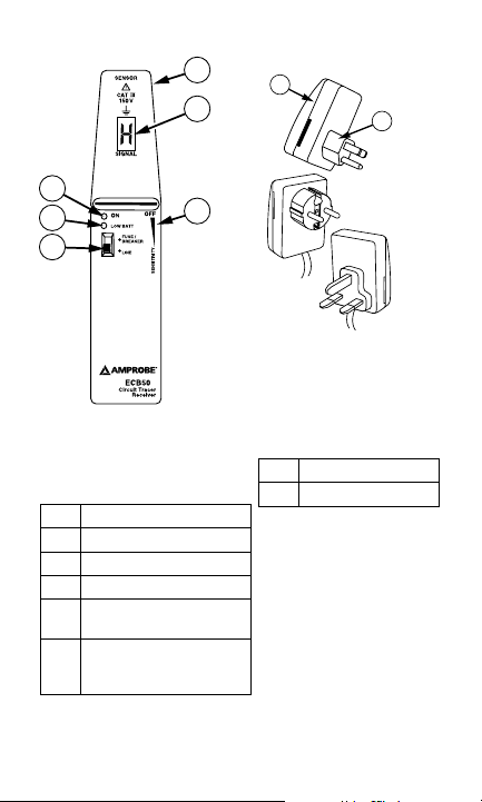
ECB50A Receiver
2
1
ECB50
A
ECB50A-E
ECB50A-FGIS
1
2
3
4
5
6
Sensor
On / Pulse LED
Low Battery Indicator
Fuse- Line mode switch
On/Off-and sensitivity
adjustment switch
Code Display. “H”
indicates signal
received.
ECB50A Transmitter
1
Handgrip
2
Plug connector
2
Page 11

Safety Information
To avoid possible electric shock or personal injury, follow these guidelines:
• Do not use the transmitter/receiver if it is damaged.
Before you use the transmitter/receiver, inspect the
case. Look for cracks or missing plastic. Pay particular
attention to the insulation surrounding the connectors.
• If this product is used in a manner not specified by the
manufacturer, the protection provided by the equipment
may be impaired.
• Do not use the transmitter/receiver if it operates
abnormally. Protection may be impaired. When in doubt,
have the transmitter/receiver serviced.
• Do not attempt to repair this transmitter/receiver. There
are no user serviceable parts.
• Use caution when working above 30 V ac rms, 42 V peak,
or 60 V dc. Such voltages pose a shock hazard.
• Do not operate the transmitter/receiver with the battery
door removed or loosened.
• CAT III equipment is designed to protect against
transients in equipment in fixed-equipment installations,
such as distribution panels, feeders and short branch
circuits, and lighting systems in large buildings.
Symbols Used in this Manual
Symbols on the instrument and in the instruction manual:
Warns of
potential danger.
Refer to the
manual
Double insulated.
Continuous
double or
reinforced
insulation
complies to IEC
536, Class II
Dangerous Voltage
Symbol of conformity,
confirms conformity with
relevant EU directives. The
instrument complies with the
EMC Directive (89/ 336/ EEC)
specifically standards EN500811 and EN50082-1, as well as
the Low Voltage Directive
(73/23/EEC) described in the
standard EN61010-1.
UL UL 1244
3
Page 12

Introduction
The ECB50A Circuit Breaker Finder and AC Cable Locator
consists of a transmitter and a receiver. Similar to radio signals,
the transmitter functions by means of a coded carrier sending
a signal into the cable. Using the built-in sensor, the receiver
can indicate the transmitted code as a symbol on the display
as well as providing an audible signal. The audible sound level
automatically intensifies as the source is approached.
The ECB50A is the ideal tracing instrument for sorting out
AC wires in a bundle of cables, tracing lines in overhead
installations and walls, and assigning current circuits to fuses.
Using the ECB50A you can:
• Sort out a single wire in a bundle of cables.
• Trace and find AC cable in walls.
• Assign current circuits to fuses within fuse panels.
• Switch between locating cable lines or locating fuses.
• Adjust sensitivity when tracing lines and locating cables.
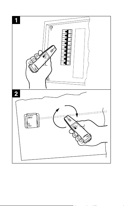
Finding Circuit Breakers and Fuses See Figure -1-
1. Turn on the ECB50A receiver using the On/Off switch.
2. Set the Fuse/Line switch to the Fuse position.
3. Plug the ECB50A transmitter into the voltage socket
connected to the fuse or circuit breaker.
4. Turn the On/Off switch toward the top of the receiver to
set sensitivity to the highest sensitivity level. Turn toward
the bottom of the receiver to reduce sensitivity.
5. Position the receiver at a 90 degree angle (perpendicular)
over the top of the fuse or circuit breaker. Adjust the
sensitivity level until the “H” code is displayed along with
a blinking LED and an audible tone.
6. If a reception signal is received at several fuses/circuit
breakers, use the On/Off switch to reduce the sensitivity
until the minimum reception is received. Repeat this
procedure until only one fuse indicates a reception signal.
This fuse/circuit breaker protects the socket to which
the transmitter has been connected. The tracing depth
amounts to approximately 10 cm (4 in).
Keep hands clear of wiring when tracing wires or fuses in
distribution panels.
Caution
4
Page 13

Locating and Tracing Cables in Walls See Figure -2-
1. Turn on the receiver using the On/Off switch.
2. Set the Fuse/Line switch to the Line position.
3. Plug the ECB transmitter into the socket for AC line to be
traced.
4. Turn the On/Off switch toward the top of the receiver to
set sensitivity to the highest sensitivity level. Turn toward
the bottom of the receiver to reduce sensitivity.
5. Place the ECB50A receiver close to the transmitter to
receive a confirmation signal that both ECB50A test
components are active and working. The receiver is
receiving a signal from the transmitter when it displays
the letter “H” on the display and the LED is blinking.
Also an audible signal is present with varied loudness
depending on strength of signal received.
6. Next, begin locating the signal in the cable to be traced
by circling around the socket. When you receive a
signal, reduce the sensitivity until the minimum signal
is received. If the signal decreases, the receiver is either
moving off the AC cable path or the cable is installed
deeper into the wall. If necessary, adjust the sensitivity
level to increase the signal strength. Depending on local
conditions, the tracing depth amounts to approx. 0 to 40
cm (0 to 15 inches).
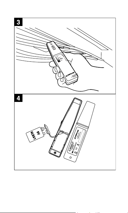
Sorting Out a Single Wire in a Bundle of Cables
See Figure -3-
1. Turn on the receiver using the On/Off switch.
2. Set the Fuse/Line switch to the Line position.
3. Plug the ECB transmitter into the socket of the AC wire to
be traced.
4. Turn the On/Off switch toward the top of the receiver to
set sensitivity to the highest sensitivity level. Turn toward
the bottom of the receiver to reduce sensitivity.
5. Place the ECB50A receiver close to the transmitter to
receive a confirmation signal that both ECB50A test
components are active and working. The receiver is
receiving a signal from the transmitter when it displays
the letter “H” on the display and the LED is blinking.
Also an audible signal is present with varied loudness
depending on strength of signal received.
5
Page 14

6. Next, try to locate the transmitted signal at the bundle of
cables. When you receive a signal, reduce the sensitivity
until the minimum reception of the signal is heard and
seen. If necessary, increase the sensitivity somewhat to
confirm the signal.
Product Maintenance
As long as the instructions in this manual are followed, no
special maintenance is required.
Cleaning
Disconnect the instrument from all circuits. To clean the
transmitter/receiver, use a soft cloth moistened with water. To
avoid damage to the plastic components do not use benzene,
alcohol, acetone, ether, paint thinner, lacquer thinner, ketone
or other solvents to clean the transmitter/receiver. Allow a
recovery time of 6 hours after cleaning before operating the
instrument.
Replacing the Battery See Figure -4-
A red LED indicates that the battery needs to be replaced. To
replace the battery:
1. Turn off the instrument using the On/Off switch
2. Loosen the screw on the back of the instrument and open
the case.
3. Remove the battery and insert the new 9 V alkaline
battery using the correct polarity. Recycle your discharged
battery.
4. Reassemble the case.
5. Insert the screw and tighten it.
Specifications
Humidity: Valid for 23 °C ± 5°, for less than 80% relative
humidity)
Transmitter
Voltage range: 100 V to 125 V for ECB50A; 100 V to 250 V for
ECB50A-E and ECB50A-FGIS
Power consumption: approximately 1 W
Frequency range: 30 to 70 Hz for ECB50A; 50 to 60 Hz for
ECB50A-E, ECB50A-FGIS
Transmission frequency: approximately 8 kHz
Transmitter frequency: approximately 10 Hz
6
Page 15

Temperature range: -10 °C to 40 °C at maximum 80% relative
humidity
Dimensions: 70 x 55 x 86 mm (2.8 x 2.1 x 3.4 in)
Weight: approximately 65 g (2.3 oz)
Overvoltage category: CAT III 150 V ECB50A, Cat III 300 V
ECB50A-E, and ECB50A-FGIS, UL 1244
Pollution degree: 2
Protection class: IP20
Receiver
Tracing depth for fuse identification: approximately 0 to 10
cm (4 in) depending on local conditions
Tracing depth for cable location: approximately 0 to 40 cm
(15 in) depending on local conditions.
Sensitivity setting: Using On/Off control potentiometer
Low battery indication: 7.5 V
Switching fuse/cable: manually using Fuse-Line switch
Temperature range: -10 °C to 40 °C (14 ° to 104 °F) at
maximum 80% relative humidity
Dimensions: 22 x 162 x 34 mm ( 0.9 x 6.4 x 1.3 in)
Weight: approximately 100 g (3.5 oz)
Overvoltage category: CAT III 150 V ECB50A, Cat III 300 V
ECB50A-E, and ECB50A-FGIS, UL 1244
Pollution degree: 2
Protection class: IP20
Power supply: 9 V battery, IEC 6LR61, Alkaline only
Applicable directives and standards: EMC: EN 50081-1,
EN 50082-1 ECB50A, Cat III 300 V ECB50A-E, and ECB50A-FGIS,
UL 1244 Low Voltage Directive: EN 61010-1 ECB50A-E and
ECB50A-FGIS
7
Page 16

Limited Warranty and Limitation of Liability
Your Amprobe product will be free from defects in material
and workmanship for 1 year from the date of purchase. This
warranty does not cover fuses, disposable batteries or damage
from accident, neglect, misuse, alteration, contamination, or
abnormal conditions of operation or handling. Resellers are
not authorized to extend any other warranty on Amprobe’s
behalf. To obtain service during the warranty period, return
the product with proof of purchase to an authorized Amprobe
Test Tools Service Center or to an Amprobe dealer or distributor.
See Repair Section for details. THIS WARRANTY IS YOUR ONLY
REMEDY. ALL OTHER WARRANTIES - WHETHER EXPRESS,
IMPLIED OR STAUTORY - INCLUDING IMPLIED WARRANTIES OF
FITNESS FOR A PARTICULAR PURPOSE OR MERCHANTABILITY,
ARE HEREBY DISCLAIMED. MANUFACTURER SHALL NOT
BE LIABLE FOR ANY SPECIAL, INDIRECT, INCIDENTAL OR
CONSEQUENTIAL DAMAGES OR LOSSES, ARISING FROM ANY
CAUSE OR THEORY. Since some states or countries do not
allow the exclusion or limitation of an implied warranty or of
incidental or consequential damages, this limitation of liability
may not apply to you.
8
Page 17

Repair
All test tools returned for warranty or non-warranty repair or
for calibration should be accompanied by the following: your
name, company’s name, address, telephone number, and proof
of purchase. Additionally, please include a brief description of
the problem or the service requested and include the test leads
with the meter. Non-warranty repair or replacement charges
should be remitted in the form of a check, a money order, credit
card with expiration date, or a purchase order made payable to
Amprobe® Test Tools.
In-Warranty Repairs and Replacement – All
Countries
Please read the warranty statement and check your battery
before requesting repair. During the warranty period any
defective test tool can be returned to your Amprobe® Test
Tools distributor for an exchange for the same or like product.
Please check the “Where to Buy” section on www.amprobe.com
for a list of distributors near you. Additionally, in the United
States and Canada In-Warranty repair and replacement units
can also be sent to a Amprobe® Test Tools Service Center (see
address below).
Non-Warranty Repairs and Replacement – US and Canada
Non-warranty repairs in the United States and Canada
should be sent to a Amprobe® Test Tools Service Center. Call
Amprobe® Test Tools or inquire at your point of purchase for
current repair and replacement rates.
In USA In Canada
Amprobe Test Tools Amprobe Test Tools
Everett, WA 98203 Mississauga, ON L4Z 1X9
Tel: 877-AMPROBE (267-7623) Tel: 905-890-7600
9
Page 18

Non-Warranty Repairs and Replacement – Europe
European non-warranty units can be replaced by your
Amprobe® Test Tools distributor for a nominal charge. Please
check the “Where to Buy” section on www.amprobe.com for a
list of distributors near you.
European Correspondence Address*
Amprobe® Test Tools Europe
P.O. Box 1186
5602 BD Eindhoven
The Netherlands
*(Correspondence only – no repair or replacement available
from this address. European customers please contact your
distributor.)
10
Page 19
11
Page 20
12
Page 21

ECB50A, ECB50A-E,
ECB50A-FGIS
Circuit Breaker Finder
and AC Line Tracer
Users Manual
• Mode d’emploi
• Bedienungshandbuch
• Manuale d’ Uso
• Manual de uso
French
Francias
Page 22

14
Page 23

Détecteurs de câbles secteur et de
disjoncteurs ECB50A, ECB50A-E et
ECB50A-FGIS
Table des matières
Consignes de sécurité ..................................................................... 3
Symboles utilisés dans ce mode d’emploi .................................. 3
Introduction .................................................................................... 4
Localisation des disjoncteurs et
des fusibles Voir figure -1- ...................................................... 4
Localisation et dépistage des
câbles dans les parois Voir figure -2- ..................................... 5
Identification d’un fil dans un
faisceau de câbles Voir figure -3- ........................................... 5
Entretien du produit ...................................................................... 6
Remplacement de la pile
Voir figure -4- ............................................................................ 6
Caractéristiques .............................................................................. 6
Limites de Garantie et de Responsabilité ..................................... 8
Réparation ...................................................................................... 9
1
Page 24

6
5
1
2
3
4
A
2
1
ECB50
A
ECB50A-E
ECB50A-FGIS
Récepteur ECB50A
1
2
3
4
5
6
Détecteur
Témoin Marche / Impulsion
Indicateur de pile faible
Commutateur de mode fusible-secteur
Bouton de réglage de sensibilité et marche/arrêt
Affichage des codes. « H » indique un signal reçu.
2
1
2
Poignée
Connecteur
Page 25

Consignes de sécurité
Pour éviter tout risque d’électrocution ou de blessure
corporelle, respecter les consignes suivantes :
• Ne pas utiliser l’émetteur/récepteur s’il est endommagé.
Avant d’utiliser l’émetteur/récepteur, inspecter son
boîtier. Rechercher les éventuelles fissures ou les
parties de plastique manquantes.Faire particulièrement
attention à l’isolant entourant les connecteurs.
• Ne pas utiliser l’émetteur/récepteur s’il ne fonctionne pas
normalement. Sa protection est peut-être défectueuse.
En cas de doute, faire réviser l’émetteur/récepteur.
• Ne pas tenter de réparer cet émetteur/récepteur. Il ne
contient pas de pièces pouvant être remplacées par
l’utilisateur.
• Ne pas tenter de réparer cet émetteur/récepteur. Il ne
contient pas de pièces pouvant être remplacées par
l’utilisateur.
• Procéder avec prudence en travaillant avec des tensions
supérieures à 30 V c.a. efficace, 42 V maximum ou 60 V
c.c. Ces tensions présentent un risque d’électrocution.
• Ne pas utiliser l’émetteur/récepteur avec le couvercle de
batterie démonté ou desserré.
• Les appareils CAT III sont conçus pour protéger contre les
tensions transitoires dans les installations d’équipements
fixes, notamment sur les panneaux de distribution
électrique, les lignes d’alimentation et les circuits dérivés
courts ainsi que les installations d’éclairage dans les
grands bâtiments.
Symboles utilisés dans ce mode d’emploi
Symboles sur l’instrument et dans le mode d’emploi :
Signale un danger
potentiel. Se
reporter au mode
d’emploi
Double isolation.
Isolation renforcée
ou double continue
conforme à CEI 536,
classe II
Tension dangereuse
P
Ce symbole confirme la
conformité aux directives EU
pertinentes. L’appareil est
conforme à la directive CEM (89/
336/CEE) aux normes spécifiques
EN50081-1 et EN50082-1, et à la
directive sur les basses tensions
(73/23/CEE) décrite dans la
norme EN61010-1.
UL UL 1244
3
Page 26

Introduction
L’identificateur de disjoncteur ECB50A et le localiseur de
câbles secteur consistent en un émetteur et un récepteur.
L’émetteur s’apparente aux signaux radioélectriques en utilisant
une porteuse codée pour envoyer un signal dans le câble.
Un capteur intégré permet au récepteur d’indiquer le code
transmis sous forme de symbole sur l’affichage et de produire
un signal sonore. Le niveau du signal sonore s’intensifie
automatiquement à mesure que la source se rapproche.
L’ECB50A est un appareil de dépistage idéal pour identifier les fils à
courant alternatif dans un faisceau de câbles, localiser les lignes dans
les installations aériennes et dans les parois, et affecter les circuits
électriques aux fusibles.
L’utilisation du ECB50A permet de :
• distinguer un fil dans un faisceau de câbles ;
• localiser et identifier un câble c.a. dans les parois ;
• affecter les circuits électriques aux fusibles dans les
panneaux de fusibles ;
• basculer entre la localisation des lignes câblées et des
fusibles ;
• ajuster la sensibilité pendant la localisation des lignes et
l’identification des câbles.
Localisation des disjoncteurs et
des fusibles Voir figure -1-
1. Mettez le récepteur ECB50A sous tension en utilisant le
bouton On/Off.
2. Réglez le commutateur Fuse/Line sur la position réservée au
fusible.
3. Branchez l’émetteur ECB50A dans la prise de tension reliée
au fusible ou au disjoncteur.
4. Tournez le bouton On/Off vers le haut du récepteur pour
régler le plus haut niveau de sensibilité possible. Tournez le
bouton vers le bas du récepteur pour réduire la sensibilité.
Positionnez le récepteur à 90 degrés (perpendiculaire) au-
5.
dessus du fusible ou du disjoncteur.
6. Si un signal de réception est reçu au niveau de plusieurs
fusibles/disjoncteurs, utilisez le bouton On/Off (marche/arrêt)
pour réduire la sensibilité de façon à obtenir une réception
minimale. Répétez cette procédure pour n’obtenir un signal
de réception que d’un seul fusible. Ce fusible/disjoncteur
protège les prises dans lesquelles l’émetteur est branché. La
profondeur de dépistage est d’environ 10 cm (4 pouces).
4
Page 27

Éloigner les mains du câblage pendant le dépistage des
fils ou des fusibles dans les panneaux électriques.
Localisation et dépistage des câbles
dans les parois Voir figure -2-
1. Mettez le récepteur sous tension en utilisant le bouton On/Off.
2. Réglez le commutateur Fuse/Line sur la position Line.
3. Branchez l’émetteur ECB dans la prise de la ligne secteur à
localiser.
4. Tournez le bouton On/Off vers le haut du récepteur pour régler le
plus haut niveau de sensibilité possible. Tournez le bouton vers le
bas du récepteur pour réduire la sensibilité.
5. Placez le récepteur ECB50A à proximité de l’émetteur pour
recevoir un signal confirmant que les deux composants ECB50A
sont actifs et fonctionnels pour le test. Le récepteur reçoit un
signal de l’émetteur à l’apparition de la lettre « H » sur l’affichage
et du voyant clignotant. Un signal sonore retentit également avec
une intensité variable selon la force du signal reçu.
6. Lancez ensuite la recherche du signal dans le câble concerné en
décrivant des cercles autour de la prise. Une fois le signal reçu,
réduisez la sensibilité jusqu’à l’obtention d’un signal minimum.
Si le signal diminue, cela signifie que le récepteur s’éloigne du
câble secteur ou que le câble se trouve plus profondément dans la
paroi. Ajustez le niveau de sensibilité s’il y a lieu pour augmenter
la puissance du signal. Selon les conditions locales, la profondeur
de dépistage se situe entre 0 et 40 cm (0 à 15 pouces).
Attention
Identification d’un fil dans un
faisceau de câbles Voir figure -3-
1. Mettez le récepteur sous tension en utilisant le bouton On/Off.
2. Réglez le commutateur Fuse/Line sur la position Line.
3. Branchez l’émetteur ECB dans la prise de la ligne secteur à
localiser.
4. Tournez le bouton On/Off vers le haut du récepteur pour régler le
plus haut niveau de sensibilité possible. Tournez le bouton vers le
bas du récepteur pour réduire la sensibilité.
5. Placez le récepteur ECB50A à proximité de l’émetteur pour recevoir
un signal confirmant que les deux composants ECB50A sont actifs et
fonctionnels pour le test. Le récepteur reçoit un signal de l’émetteur à
l’apparition de la lettre « H » sur l’affichage et du voyant clignotant. Un
signal sonore retentit également avec une intensité variable selon la
force du signal reçu.
6. Essayez ensuite de localiser le signal transmis au niveau du faisceau
de câbles. Une fois le signal reçu, réduisez la sensibilité jusqu’à la
confirmation visuelle et sonore de la réception d’un signal minimum.
Augmentez la sensibilité s’il y a lieu pour confirmer le signal.
5
Page 28

Entretien du produit
Aucune maintenance particulière n’est exigée dans la mesure
où les consignes de ce manuel sont respectées.
Nettoyage
Débranchez l’instrument de tous les circuits. Nettoyer l’émetteur/
récepteur à l’aide d’un chiffon doux imbibé d’eau. Afin de ne
pas endommager les composants en plastique, ne pas utiliser de
benzène, d’alcool, d’acétone, d’éther, de diluant pour peinture
ou peinture-laque, de cétone ou d’autres solvants pour nettoyer
l’émetteur/récepteur. Prévoyez un délai de 6 heures après le
nettoyage avant de recommencer à utiliser l’appareil.
Remplacement de la pile Voir figure -4-
Un voyant rouge indique que la pile doit être remplacée. Pour
la remplacer :
1. Mettez l’appareil hors tension en utilisant le bouton On/Off.
2. Desserrez la vis au dos de l’appareil et ouvrez le boîtier.
3. Retirez la pile et insérez la nouvelle pile alcaline de 9 V en
utilisant la polarité correcte. Recyclez la pile usagée.
4. Remontez le boîtier.
5. Insérez la vis et serrez-la.
Caractéristiques
Humidité : Valable à 23°C ± 5°, avec moins de 80 % d’humidité
relative)
Emetteur
Gamme de tension : 100 V à 125 V pour ECB50A ; 100 V à 250
V pour ECB50A-E et ECB50A-FGIS
Consommation d’énergie : environ 1 W
Gamme de fréquence : 30 à 70 Hz pour ECB50A ; 50 à 60 Hz
pour ECB50A-E et ECB50A-FGIS
Fréquence d’émission :
Fréquence d’émetteur : environ 10 Hz
Plage de température : de -10 °C à 40 °C avec 80 %
d’humidité relative maximum
Dimensions : 70 x 55 x 86 mm (2,8 x 2,1 x 3,4 pouces)
Poids : environ 65 g (2,3 oz)
environ 8 kHz
Catégorie de surtension : CAT III 150 V ECB50A, CAT III 300 V
ECB50A-E et ECB50A-FGIS UL 1244
Degré de pollution : 2
Classe de protection : IP20
6
Page 29

Récepteur
Profondeur de dépistage pour l’identification des
fusibles : de 0 à 10 cm
(4 pouces) environ en fonction des conditions locales
Profondeur de dépistage pour l’identification des câbles :
de 0 à 40 cm (14 pouces) environ en fonction des conditions
locales.
Réglage de sensibilité :
marche/arrêt (OFF)
Témoin de pile faible :
Commutation fusible/câble :
commutateur Fuse-Line
Plage de température : de -10 °C à 40 °C (14 ° à 104 °F) avec
80 % d’humidité relative maximum
Dimensions : 22 x 162 x 34 mm (0,9 x 6,4 x 1,3 pouces)
Poids : environ 100 g (99,22 g)
Catégorie de surtension : CAT III 150 V ECB50A, CAT III 300 V
ECB50A-E et ECB50A-FGIS
Degré de pollution :
Classe de protection :
Alimentation : Pile de 9 V, CEI 6LR61, alcaline uniquement
Normes et directives applicables : CEM : EN 50081-1, EN 50082-1
ECB50A
EN 50082-2 ECB50A-E et ECB50A-FGIS
Directive sur les basses tensions : EN 61010-1 ECB50A-E et
ECB50A-FGIS
à l’aide du potentiomètre de réglage
7,5 V
utilisation manuelle du
2
IP20
7
Page 30

Limites de Garantie et de Responsabilité
Amprobe garantit l’absence de vices de matériaux et de
fabrication de ce produit dans des conditions normales
d’utilisation et d’entretien pendant une période d’un an
prenant effet à la date d’achat. Cette garantie ne s’applique
pas aux fusibles, aux piles jetables ni à tout produit mal
utilisé, modifié, contaminé, négligé ou endommagé par
accident ou soumis à des conditions anormales d’utilisation
et de manipulation. Les distributeurs agréés par Amprobe ne
sont pas autorisés à appliquer une garantie plus étendue au
nom de Amprobe. Pour bénéficier de la garantie, renvoyez
le produit accompagné d’un justificatif d’achat auprès d’un
centre de services agréé par Amprobe Test ou du distributeur
ou du revendeur Amprobe. Voir la section Réparation ci-dessus
pour tous les détails. LA PRESENTE GARANTIE EST LE SEUL ET
EXCLUSIF RECOURS TOUTES AUTRES GARANTIES, EXPLICITES,
IMPLICITES OU STATUTAIRES, NOTAMMENT LE CAS ECHEANT
LES GARANTIES DE QUALITE MARCHANDE OU D’ADAPTATION A
UN OBJECTIF PARTICULIER SONT EXCLUES PAR LES PRESENTES.
LE FABRICANT NE SERA EN AUCUN CAS TENU RESPONSABLE
DE DOMMAGES PARTICULIERS, INDIRECTS, ACCIDENTELS OU
CONSECUTIFS, NI D’AUCUNS DEGATS OU PERTES DE DONNEES,
SUR UNE BASE CONTRACTUELLE, EXTRA-CONTRACTUELLE OU
AUTRE. Etant donné que certains pays ou états n’admettent
pas les limitations d’une condition de garantie implicite, ou
l’exclusion ou la limitation de dégâts accidentels ou consécutifs,
les limitations et les exclusions de cette garantie ne s’appliquent
pas obligatoirement à chaque acheteur.
8
Page 31

Réparation
Tous les appareils qui sont envoyés pour réparation ou calibrage
dans le cadre de la garantie ou en dehors de la garantie
doivent être accompagnés de ce qui suit: Nom du client, nom
de la firme, adresse, numéro de téléphone et preuve d’achat.
Prière de joindre en outre à l’appareil de mesure une brève
description du problème ou de la maintenance désirée ainsi que
les lignes de mesure. Les frais pour les réparations en dehors de
la garantie ou pour le remplacement d’instruments doivent être
payés par chèque, virement bancaire, carte de crédit (numéro
de carte de crédit avec date d’expiration) ou une commande
doit être formulée au bénéfice de Amprobe Test Tools..
Remplacements et réparations sous garantie – Tous pays
Veuillez lire la déclaration de garantie subséquente et
contrôler la pile avant de demander des réparations. Pendant
la période de garantie, tous les appareils défectueux peuvent
être renvoyés à un distributeur Amprobe Test Tools pour
remplacement par un appareil identique ou un produit
similaire. Un répertoire des distributeurs agréés se trouve
dans la section « Where to Buy » (points de vente) sur le site
web www.amprobe.com. De plus, aux USA et au Canada,
les appareils peuvent être envoyés à un centre de service
après-vente Amprobe Test Tools (adresse voir plus loin) pour
réparation ou remplacement.
Réparations ou remplacement en dehors de la garantie
- USA et Canada
Pour les réparations en dehors de la garantie aux Etats-Unis et
au Canada, les appareils sont envoyés à un centre de service
après-vente Amprobe Test Tools. Vous pouvez obtenir des
renseignements sur les prix de réparation et de remplacement
actuellement en vigueur auprès de Amprobe Test Tools ou du
point de vente.
Aux USA : Au Canada :
Amprobe Test Tools Amprobe Test Tools
Everett, WA 98203 Mississauga, ON L4Z 1X9
Tél.: 877-AMPROBE (267-7623) Tél.: 905-890-7600
9
Page 32

Réparations ou remplacement en dehors de la garantie
- Europe
Les appareils hors garantie peuvent être remplacés contre
paiement par le distributeur Amprobe Test Tools compétent. Un
répertoire des distributeurs agréés se trouve dans la section «
Where to Buy » (points de vente) sur le site web www.amprobe.
com.
Adresse de correspondance pour l’Europe*
Amprobe Test Tools Europe
P. O. Box 1186
5602 BD Eindhoven
Pays-Bas
*(Uniquement correspondance – pas de réparations, pas de
remplacement à cette adresse. Les clients en Europe s’adressent
au distributeur compétent.)
.
10
Page 33

ECB50A, ECB50A-E,
and ECB50A-FGIS
Circuit Breaker Finder
and AC Line Tracer
Users Manual
• Mode d’emploi
• Bedienungshandbuch
• Manuale d’ Uso
• Manual de uso
German
Deutsch
Page 34

Page 35

ECB50A, ECB50A-E und ECB50A-FGIS
zum Auffinden von Trennschaltern und
Wechselstromkabeln
Inhalt
Sicherheitsinformationen .............................................................. 3
Symbole in diesem Handbuch .................................................... 4
Einleitung ....................................................................................... 4
Auffinden von Trennschaltern und
Sicherungen Siehe Abbildung -1- ........................................... 5
Auffinden und Verfolgen von Kabeln in
Wänden Siehe Abbildung -2- ................................................. 5
Aussortieren eines Kabels in einem
Bündel von Kabeln Siehe Abbildung -3- .............................. 6
Produktwartung ............................................................................. 6
Reinigung ..................................................................................... 6
Ersetzen der Batterie Siehe Abbildung -4- ............................. 7
Technische Daten ........................................................................... 7
Beschränkte Gewährleistung und Haftungsbeschränkung ......... 9
Reparatur ........................................................................................ 9
1
Page 36

6
5
1
2
3
4
A
2
1
ECB50
A
ECB50A-E
ECB50A-FGIS
ECB50A Empfänger
1
2
3
4
5
6
Sensor
Ein / Impuls-LED
Anzeige für schwache Batterie
Sicherungs-/Leitungsschalter
Ein/Aus- und Empfindlichkeitseinstellungs-
Schalter
Codeanzeige. „H“ zeigt Signal empfangen an.
1
Handgriff
2
Stecker
2
Page 37

Sicherheitsinformationen
Zur Vermeidung von Stromschlag oder Verletzungen folgende
Richtlinien einhalten:
• Den Sender/Empfänger nicht verwenden, wenn
er beschädigt ist. Vor dem Gebrauch des Senders/
Empfängers das Gehäuse untersuchen. Nach Rissen
oder herausgebrochenem Kunststoff suchen. Die
Isolierung im Bereich der Anschlüsse besonders
sorgfältig untersuchen.
• Wenn dieses Produkt in einer hier nicht
beschriebenen Art verwendet wird, wird der durch
das Gerät gebotene Schutz unter Umständen
beeinträchtigt.
• Den Sender/Empfänger nicht verwenden, wenn
das Gerät Funktionsstörungen aufweist. Unter
Umständen sind die Sicherheitsvorkehrungen
beeinträchtigt. Im Zweifelsfall den Sender/
Empfänger von einer Servicestelle prüfen lassen.
• Nicht versuchen diesen Sender/Empfänger zu
reparieren. Es gibt keine kundenseitig wartbaren
Teile.
• Bei Arbeiten mit mehr als 30 V Wechselspannung
eff., 42 V Spitze oder 60 V Gleichspannung
Vorsicht walten lassen. Solche Spannungen bergen
Stromschlaggefahr.
• Den Sender/Empfänger nicht betreiben, wenn die
Batteriefachabdeckung entfernt oder lose ist.
• Die CAT III-Ausrüstung ist so konzipiert, dass
sie gegen impulsförmige Störsignale in fest
installierten Geräten wie z. B. Verteilertafeln,
Zuleitungen und kurze Verzweigungsstromkreise
und Beleuchtungssystemen in großen Gebäuden
schützt.
3
Page 38

Symbole in diesem Handbuch
Symbole am Instrument und im Bedienungshandbuch:
Weist auf potenzielle
Gefahren hin. Im
Handbuch nachlesen.
Schutzisoliert.
Ununterbrochene
Schutzisolierung und
verstärkte Isolierung in
Übereinstimmung mit
IEC 536, Klasse II
Einleitung
Das ECB50A-Gerät zum Auffinden von Trennschaltern und
Wechselstromkabeln besteht aus einem Sender und einem
Empfänger. Der Sender nutzt ein kodiertes Trägersignal, das
auf ähnliche Weise wie ein Funksignal in das Kabel übertragen
wird. Unter Verwendung des eingebauten Sensors kann der
Empfänger den übertragenen Code als Symbol auf der Anzeige
und auch als akustisches Signal anzeigen. Der akustische Pegel
wird beim Annähern an die Quelle automatisch verstärkt.
Das ECB50A ist das ideale Ortungsinstrument zum Aussortieren von
Wechselstromkabeln in Bündeln von Kabeln, Verfolgen von Leitungen
in Freikabelstrecken und Wänden und Zuordnen von Stromkreisen zu
Sicherungen.
Verwendung des ECB50A:
• Aussortieren eines Kabels in einem Bündel von Kabeln.
• Auffinden/Verfolgen von Wechselstromkabeln in
Wänden.
• Zuordnen von Stromkreisen zu Sicherungen in
Sicherungsfeldern.
• Umschalten zwischen Orten von Kabeln und Orten von
Sicherungen.
• Einstellen der Empfindlichkeit für das Verfolgen von
Leitungen/Orten von Kabeln.
Gefährliche Spannung
Symbol bestätigt
Konformität mit
relevanten EU-Richtlinien.
Das Instrument stimmt
überein mit: EMCRichtlinie (89/ 336/ EEC),
insbesondere EN50081-1
und EN50082-1 und auch
Niederspannungsrichtlinie
(73/23/EEC), beschrieben in
EN61010-1.
UL UL 1244
4
Page 39

Auffinden von Trennschaltern
und Sicherungen Siehe Abbildung -1-
1. Den ECB50A Empfänger unter Verwendung des Ein/Aus-
Schalters einschalten.
2. Den Sicherungs-/Leitungsschalter in die Sicherungsposition
schalten.
3. Den ECB50A Sender in die Steckdose einstecken, die mit der
Sicherung bzw. dem Trennschalter verbunden ist.
4. Den Ein/Aus-Schalter des Empfängers zur Oberseite des
Empfängers drehen, um die Empfindlichkeit auf den höchsten
Pegel einzustellen. Den Schalter nach unten drehen, um die
Empfindlichkeit zu reduzieren.
5. Den Empfänger in einem Winkel von 90 Grad (rechtwinklig)
über der Sicherung bzw. dem Trennschalter positionieren.
6. Wenn bei mehreren Sicherungen/Trennschaltern ein
Empfangssignal festgestellt wird, die Empfindlichkeit mit
dem EIN/AUS-Schalter reduzieren, bis das minimale Signal
empfangen wird. Dieses Verfahren wiederholen bis lediglich
eine Sicherung ein Empfangssignal anzeigt. Diese Sicherung/
dieser Trennschalter schützt die Steckdose, die mit dem Sender
verbunden ist. Die Ortungstiefe beträgt ungefähr 10 cm.
Beim Orten/Verfolgen von Drähten oder Sicherungen in Verteilfeldern
die Hände in sicherem Abstand zu den Drähten halten.
Auffinden und Verfolgen von Kabeln in Wänden
Siehe Abbildung -2-
1. Den Empfänger unter Verwendung des Ein/Aus-Schalters
einschalten.
2. Den Sicherungs-/Leitungsschalter in die Leitungsposition
schalten.
3. Den ECB Sender in die Steckdose des zu verfolgenden
Wechselstrom-Stromkreises stecken.
4. Den Ein/Aus-Schalter zur Oberseite des Empfängers drehen,
um die Empfindlichkeit auf den höchsten Pegel einzustellen.
Den Schalter des Empfängers nach unten drehen, um die
Empfindlichkeit zu reduzieren.
5. Den ECB50A Empfänger nahe zum Sender führen, um ein
Signal zu empfangen, das bestätigt, dass beide ECB50A
Testkomponenten aktiviert sind und funktionieren. Der
Empfänger empfängt ein Signal des Senders, wenn die Anzeige
des Empfängers den Buchstaben „H“ anzeigt und die LED blinkt.
Darüber hinaus wird ein akustisches Signal ausgegeben, dessen
Vorsicht
5
Page 40

Lautstärke von der Stärke des empfangenen Signals abhängt.
6. Durch Einkreisen in der Umgebung der Steckdose mit der
Ortung des Signals im zu verfolgenden Kabel beginnen.
Wenn ein Signal empfangen wird, die Empfindlichkeit
reduzieren, bis das minimale Signal empfangen wird. Wenn
das Signal schwächer wird, wird entweder der Empfänger
von der Wechselstromkabelstrecke weggeführt oder das
Kabel ist tiefer in der Wand installiert. Falls erforderlich, den
Empfindlichkeitspegel anpassen, um die Signalstärke zu erhöhen.
Abhängig von den jeweiligen Bedingungen vor Ort beträgt die
Ortungstiefe ungefähr 0 bis 40 cm.
Aussortieren eines Kabels in einem Bündel von Kabeln
Siehe Abbildung -3-
1. Den Empfänger unter Verwendung des Ein/Aus-Schalters
einschalten.
2. Den Sicherungs-/Leitungsschalter in die Leitungsposition
schalten.
3. Den ECB Sender in die Steckdose des zu verfolgenden
Wechselstrom-Stromkreises stecken.
4. Den Ein/Aus-Schalter zur Oberseite des Empfängers drehen,
um die Empfindlichkeit auf den höchsten Pegel einzustellen.
Den Schalter des Empfängers nach unten drehen, um die
Empfindlichkeit zu reduzieren.
5. Den ECB50A Empfänger nahe zum Sender führen, um ein
Signal zu empfangen, das bestätigt, dass beide ECB50A
Testkomponenten aktiviert sind und funktionieren. Der
Empfänger empfängt ein Signal des Senders, wenn die Anzeige
des Empfängers den Buchstaben „H“ anzeigt und die LED
blinkt. Darüber wird ein akustischen Signal ausgegeben, dessen
Lautstärke von der Stärke des empfangenen Signals abhängt.
6. Dann versuchen, das übertragene Signal im Bündel von Kabeln
zu orten. Wenn ein Signal empfangen wird, die Empfindlichkeit
reduzieren, bis das minimale Signal optisch und akustisch
angezeigt wird. Falls erforderlich, den Empfindlichkeitspegel
leicht erhöhen, um das Signal zu bestätigen.
Produktwartung
Solange die Anleitungen in diesem Handbuch befolgt
werden, ist keine besondere Wartung erforderlich.
Reinigung
Das Instrument von allen Stromkreisen trennen. Den Sender/
Empfänger mit einem weichen, mit Wasser angefeuchteten
Lappen reinigen. Um eine Beschädigung der Plastikteile zu
vermeiden, niemals Benzin, Alkohol, Azeton, Äther, Farb- oder
Lackverdünner, Keton oder andere Lösungsmittel zur Reinigung
6
Page 41

des Senders/Empfängers verwenden. Nach einer Reinigung
6 Stunden Erholungszeit gewähren, bevor das Instrument
wieder eingesetzt wird.
Ersetzen der Batterie Siehe Abbildung -4-
Eine rote LED zeigt an, dass die Batterie ersetzt werden muss.
Ersetzen der Batterie:
1. Das Instrument unter Verwendung des Ein/Aus-Schalters
ausschalten.
2. Die Schraube an der Rückseite des Instruments lösen und
das Gehäuse öffnen.
3. Die Batterie entfernen und eine neue alkalische 9-
V-Batterie unter Beachtung der korrekten Polarität
einsetzen. Die verbrauchte Batterie recyceln.
4. Das Gehäuse wieder zusammenbauen.
5. Die Schraube einsetzen und anziehen.
Technische Daten
Feuchtigkeit: Gültig für 23°C ± 5° (für weniger als 80 % relative
Feuchtigkeit)
Sender
Spannungsbereich:100 V bis 125 V für ECB50A; 100 V bis 250
V für ECB50A-E und ECB50A-FGIS
Stromverbrauch: ungefähr 1 W
Frequenzbereich: 30 bis 70 Hz für ECB50A; 50 bis 60 Hz für
ECB50A-E und ECB50A-FGIS
Übertragungsfrequenz: ungefähr 8 kHz
Sendefrequenz: ungefähr 10 Hz
Temperaturbereich: -10
Feuchtigkeit
Abmessungen: 70 x 55 x 86 mm
Gewicht: ungefähr 65 g
Überspannungskategorie: CAT III 150 V ECB50A, CAT III 300 V
ECB50A-E und ECB50A-FGIS UL 1244
Verschmutzungsgrad: 2
Schutzklasse: IP20
Empfänger
Ortungstiefe für Sicherungserkennung: ungefähr 0 bis 10
cm abhängig von örtlichen Bedingungen
Ortungstiefe für Kabelerkennung: ungefähr 0 bis 40 cm,
abhängig von örtlichen Bedingungen.
Empfindlichkeitseinstellung: Verwendung Ein/Aus-
°C bis 40 °C bei maximal 80 % relativer
7
Page 42

Steuerpotentiometer
Anzeige für schwache Batterie: 7,5 V
Umschalten Sicherung/Kabel: manuell mit Sicherungs-
/Leitungsschalter
Temperaturbereich: -10 °C bis 40 °C (14 ° bis 104 °F) bei
maximal 80 % relativer Feuchtigkeit
Abmessungen: 22 x 162 x 34 mm
Gewicht: ungefähr 100 g
Überspannungskategorie: CAT III 150 V ECB50A, CAT III 300 V
ECB50A-E und ECB50A-FGIS
Verschmutzungsgrad 2
Schutzklasse: IP20
Stromversorgung: 9-V-Batterie, IEC 6LR61, nur alkalisch
Geltende Richtlinien und Normen: EN 50081-1, EN 50082-1
ECB50A
EN 50082-2 ECB50A-E und ECB50A-FGIS
Niederspannungsrichtlinie: EN 61010-1 ECB50A-E und ECB50A-
FGIS
8
Page 43

Beschränkte Gewährleistung und
Haftungsbeschränkung
Es wird gewährleistet, dass dieses Amprobe-Produkt für die
Dauer von einem Jahr ab dem Kaufdatum frei von Materialund Fertigungsdefekten ist. Diese Gewährleistung erstreckt
sich nicht auf Sicherungen, Einwegbatterien oder Schäden
durch Unfälle, Nachlässigkeit, Missbrauch, Änderungen
oder abnormale Betriebsbedingungen bzw. unsachgemäße
Handhabung. Die Verkaufsstellen sind nicht dazu berechtigt,
diese Gewährleistung im Namen von Amprobe zu erweitern.
Um während der Gewährleistungsperiode Serviceleistungen
zu beanspruchen, das Produkt mit Kaufnachweis an ein
autorisiertes Amprobe Test Tools Service-Center oder an einen
Amprobe-Fachhändler/-Distributor einsenden. Einzelheiten
siehe Abschnitt „Reparatur“ oben. DIESE GEWÄHRLEISTUNG
STELLT DEN EINZIGEN UND ALLEINIGEN RECHTSANSPRUCH AUF
SCHADENERSATZ DAR. ALLE ANDEREN GEWÄHRLEISTUNGEN
- VERTRAGLICH GEREGELTE ODER GESETZLICHE
VORGESCHRIEBENE - EINSCHLIESSLICH DER GESETZLICHEN
GEWÄHRLEISTUNG DER MARKTFÄHIGKEIT UND DER EIGNUNG
FÜR EINEN BESTIMMTEN ZWECK, WERDEN ABGELEHNT DER
HERSTELLER ÜBERNIMMT KEINE HAFTUNG FÜR SPEZIELLE,
INDIREKTE, NEBEN- ODER FOLGESCHÄDEN ODER VERLUSTE,
DIE AUF BELIEBIGER URSACHE ODER RECHTSTHEORIE
BERUHEN. Weil einige Staaten oder Länder den Ausschluss
oder die Einschränkung einer implizierten Gewährleistung
sowie von Begleit- oder Folgeschäden nicht zulassen, ist diese
Gewährleistungsbeschränkung möglicherweise für Sie nicht
gültig.
Reparatur
Zu allen Geräten, die zur Reparatur oder Kalibrierung im
Rahmen der Garantie oder außerhalb der Garantie eingesendet
werden, muss folgendes beigelegt werden: Name des Kunden,
Firmenname, Adresse, Telefonnummer und Kaufbeleg.
Zusätzlich bitte eine kurze Beschreibung des Problems oder
der gewünschten Wartung sowie die Messleitungen dem
Messgerät beilegen. Die Gebühren für Reparaturen außerhalb
der Garantie oder für den Ersatz von Instrumenten müssen als
Scheck, Geldanweisung, Kreditkarte (Kreditkartennummer mit
Ablaufdatum) beglichen werden oder es muss ein Auftrag an
Amprobe Test Tools formuliert werden.
9
Page 44

Garantiereparaturen oder -austausch - alle Länder
Bitte die nachfolgende Garantieerklärung lesen und die
Batterie prüfen, bevor Reparaturen angefordert werden.
Während der Garantieperiode können alle defekten Geräte
zum Umtausch gegen dasselbe oder ein ähnliches Produkt
an den Amprobe Test Tools-Distributor gesendet werden. Ein
Verzeichnis der zuständigen Distributoren ist im Abschnitt
„Where to Buy“ (Verkaufsstellen) auf der Website www.
amprobe.com zu finden.
Darüber hinaus können in den USA und in Kanada
Geräte an ein Amprobe Test Tools Service-Center (Adresse siehe
weiter unten) zur Reparatur oder zum Umtausch eingesendet
werden.
Reparatur oder Austausch - ausserhalb der
Garantieperiode - USA und Kanada
Für Reparaturen außerhalb der Garantie in den Vereinigten
Staaten und in Kanada werden die Geräte an ein Amprobe
Test Tools Service-Center gesendet. Auskunft über die derzeit
geltenden Reparatur- und Austauschgebühren erhalten Sie von
Amprobe Test Tools oder der Verkaufsstelle.
In den USA: In Kanada:
Amprobe Test Tools Amprobe Test Tools
Everett, WA 98203 Mississauga, ON L4Z 1X9
Tel: 877-AMPROBE (267-7623) Tel: 905-890-7600
Reparaturen und Austausch außerhalb der Garantie
- Europa
Geräte außerhalb der Garantie können durch den zuständigen
Amprobe Test Tools-Distributor gegen eine Gebühr ersetzt
werden. Ein Verzeichnis der zuständigen Distributoren ist im
Abschnitt „Where to Buy“ (Verkaufsstellen) auf der Website
www.amprobe.com zu finden.
Korrespondenzanschrift für Europa*
Amprobe Test Tools Europe
P. O. Box 1186
5602 BD Eindhoven
Niederlande
*(Nur Korrespondenz – keine Reparaturen, kein Umtausch
unter dieser Anschrift. Kunden in Europa wenden sich an den
zuständigen Distributor.)
10
Page 45

ECB50A, ECB50A-E,
and ECB50A-FGIS
Circuit Breaker Finder
and AC Line Tracer
Users Manual
• Mode d’emploi
• Bedienungshandbuch
• Manuale d’ Uso
• Manual de uso
Italian
Italiano
Page 46

Page 47

Rivelatore di interruttori automatici e di
cavi elettrici in c.a.
ECB50A, ECB50A-E e ECB50A-FGIS
Indice
!Unexpected End of Formula
Informazioni sulla sicurezza .......................................................... 3
Simboli adoperati nel presente manuale ................................... 3
Introduzione ................................................................................... 4
Localisation des disjoncteurs
et des fusibles Voir figure -1- ................................................ 4
Individuazione di cavi nelle
pareti Vedi Figura -2-............................................................ 5
Individuazione di un singolo
cavo in un intero cablaggio Vedi Figura -3- ............................ 5
Manutenzione del prodotto .......................................................... 6
Pulizia ........................................................................................... 6
Sostituzione della pila Vedi Figura -4-....................................... 6
Dati tecnici ...................................................................................... 6
Garanzia limitata e limitazione di responsabilità ........................ 8
Riparazioni ...................................................................................... 9
1
Page 48

6
5
1
2
3
4
A
2
1
ECB50
A
ECB50A-E
ECB50A-FGIS
1
Impugnatura
2
Spina
Ricevitore ECB50A
1
Sensore
2
Spia ON/PULSE (Acceso/impulsi)
3
Spia Low Bat (Pila scarica)
4
Selettore di modalità Fuse (Fusibile)/Line
(Linea)
5
Interruttore di accensione/spegnimento e
regolatore di sensibilità
6
Display dei codici. “H” indica la ricezione del
segnale.
2
Page 49

Informazioni sulla sicurezza
Per prevenire possibili scosse elettriche e altre cause di
infortunio, prendere le seguenti precauzioni.
• Non usare il trasmettitore e/o il ricevitore se sembrano
danneggiati. Prima di usare il trasmettitore e/o il ricevitore,
ispezionarne l’involucro. Verificare che non vi siano incrinature
e che non manchino parti di plastica. Esaminare attentamente le
condizioni dell’isolamento attorno ai connettori.
• Usare lo strumento solo secondo queste istruzioni, o si rischia di
comprometterne la protezione interna.
• Non usare il trasmettitore e/o il ricevitore se funzionano in modo
anomalo. I dispositivi interni di protezione potrebbero essere
danneggiati. In caso di dubbi, far controllare il trasmettitore e/o il
ricevitore presso un centro di assistenza.
• Non tentare di riparare il trasmettitore e/o il ricevitore, in quanto
non contengono parti riparabili dall’utente.
• Esercitare cautela quando si lavora con corrente alternata
maggiore di 30 V c.a. (valore efficace), 42 V (picco) o 60 V c.c. Tali
livelli di tensione possono causare scosse elettriche.
• Non azionare il trasmettitore e/o il ricevitore con lo sportello della
batteria rimosso o allentato.
• Gli apparecchi CAT III sono realizzati per la protezione
dai transitori in impianti fissi, quali ad esempio quadri di
distribuzione, alimentatori, cortocircuiti derivati e impianti di
illuminazione di grandi edifici.
Simboli adoperati nel presente manuale
I seguenti sono i simboli usati sullo strumento e nel manuale di
istruzioni.
Avvertenza di
possibile pericolo.
Consultare il
manuale.
Isolamento doppio.
L’isolamento doppio
continuo o rinforzato
è conforme alla
norma IEC 536,
Classe II.
Alta tensione
Simbolo di conformità. Conferma
la conformità alle direttive
UE pertinenti. Lo strumento
è conforme alla Direttiva
89/336/CEE sulla compatibilità
elettromagnetica, e in particolare
alle norme EN50081-1 e
EN50082-1; è inoltre conforme
alla Direttiva 73/23/CEE sulle
basse tensioni, descritta nella
norma EN61010-1.
UL UL 1244
3
Page 50

Introduzione
Il rivelatore di interruttori automatici e cavi elettrici in c.a.
ECB50A si compone di un trasmettitore e di un ricevitore. Il
trasmettitore opera per mezzo di una portante codificata
che invia un segnale nel cavo, simile ai segnali radio. Grazie
al sensore incorporato, il ricevitore indica sul display il codice
trasmesso, in forma di simbolo, ed emette un segnale acustico.
Il volume della segnalazione aumenta in funzione della
prossimità al generatore.
l’ECB50A è lo strumento ideale per individuare cavi in c.a. in un
cablaggio, seguire linee elettriche in impianti aerei e pareti, e
abbinare circuiti di corrente ai relativi fusibili.
Con l’ECB50A è possibile:
• individuare un singolo cavo in un intero cablaggio;
• rilevare e seguire cavi elettrici in c.a. nelle pareti;
• abbinare circuiti di corrente ai relativi fusibili in un
quadro;
• passare dall’individuazione di cavi al rilevamento di
fusibili;
• regolare la sensibilità durante le operazioni di
rilevamento.
Localisation des disjoncteurs et des fusibles Voir figure -1-
1. Accendere il ricevitore ECB50A agendo sull’apposito
interruttore.
2. Portare il selettore Fuse/Line sulla posizione Fuse.
3. Collegare il trasmettitore ECB50A alla presa in tensione
collegata al fusibile o all’interruttore automatico.
4. Spostare verso l’alto l’interruttore di accensione/
spegnimento per regolare la sensibilità al livello massimo.
Per ridurla, spostare il regolatore verso il basso..
Avvicinare il ricevitore al fusibile o all’interruttore
5.
automatico, tenendolo a 90°, ossia perpendicolare, sopra
di esso.
6. Se il segnale proviene da più fusibili o interruttori
automatici, ridurre la sensibilità fino alla ricezione minima
agendo sull’interruttore di accensione/spegnimento.
Ripetere l’operazione fino a ricevere il segnale da un solo
fusibile. Questo fusibile/interruttore automatico protegge
la presa a cui è collegato il trasmettitore. La profondità di
rilevamento è di circa 10 cm.
4
Page 51

Quando si seguono fili o fusibili in quadri di
Attenzione
distribuzione, tenere le mani a distanza dal cablaggio.
Individuazione di cavi nelle pareti
Vedi Figura -2-
1. Accendere il ricevitore agendo sull’apposito interruttore.
2. Portare il selettore Fuse/Line sulla posizione Line.
3. Collegare il trasmettitore ECB50A alla presa della linea in c.a. da
seguire.
4. Spostare verso l’alto l’interruttore di accensione/
spegnimento per regolare la sensibilità al livello massimo.
Per ridurla, spostare il regolatore verso il basso.
5. Avvicinare il ricevitore ECB50A al trasmettitore per ricevere il
segnale di conferma che entrambi i componenti ECB50A sono
attivi e funzionanti. Alla ricezione del segnale dal trasmettitore, il
ricevitore visualizza il codice “H” sul display e la spia lampeggia.
Inoltre, emette una segnalazione acustica il cui volume aumenta
o diminuisce in funzione della potenza del segnale ricevuto.
6. Muovere lo strumento davanti alla presa, con un movimento
circolare, per iniziare a individuare il segnale del cavo da seguire.
Ricevuto il segnale, ridurre la sensibilità fino percepirlo al livello
minimo. Se il segnale diminuisce, significa che il ricevitore si sta
allontanando dal percorso del cavo o che il cavo è stato posato
in un punto più interno nella parete. Se necessario, regolare la
sensibilità per aumentare la potenza del segnale. La profondità
del cavo da seguire può variare da 0 a 40 cm circa, a seconda
delle condizioni specifiche.
Individuazione di un singolo cavo in un intero
cablaggio
Vedi Figura -3-
1. Accendere il ricevitore agendo sull’apposito interruttore.
2. Portare il selettore Fuse/Line sulla posizione Line.
3. Collegare il trasmettitore ECB50A alla presa a cui è connesso
il cavo in c.a. da seguire.
4. Spostare verso l’alto l’interruttore di accensione/
spegnimento per regolare la sensibilità al livello massimo.
Per ridurla, spostare il regolatore verso il basso.
5. Avvicinare il ricevitore ECB50A al trasmettitore per ricevere il
segnale di conferma che entrambi i componenti ECB50A sono
attivi e funzionanti. Alla ricezione del segnale dal trasmettitore, il
ricevitore visualizza il codice “H” sul display e la spia lampeggia.
Inoltre, emette una segnalazione acustica il cui volume aumenta
o diminuisce in funzione della potenza del segnale ricevuto.
5
Page 52

6. Tentare di individuare il segnale trasmesso presso il fascio di
cavi. Ricevuto il segnale, ridurre la sensibilità fino percepirlo
e vederlo al livello minimo. Se necessario, aumentare
leggermente la sensibilità per confermare il segnale.
Manutenzione del prodotto
Non è necessario alcun intervento particolare di manutenzione,
purché si usi lo strumento in conformità alle istruzioni in questo
manuale.
Pulizia
Scollegare lo strumento da tutti gli eventuali circuiti. Per pulire lo
strumento, adoperare un panno morbido inumidito con acqua.
Per evitare danni ai componenti plastici, quando si pulisce il
trasmettitore e/o il ricevitore non usare benzene, alcol, acetone,
etere, diluenti per vernice o lacca, chetoni o altri solventi. Prima di
usare di nuovo lo strumento, lasciare passare 6 ore dopo la pulizia.
Sostituzione della pila
Vedi Figura -4-
L’accensione di una spia LED rossa indica che la pila deve essere
sostituita. Per sostituire la pila, procedere come segue.
1. Spegnere lo strumento agendo sull’apposito interruttore.
2. Allentare la vite sul retro dello strumento e aprire
l’involucro.
3. Rimuovere la pila e inserirne una nuova, alcalina e da 9 V,
accertandosi che la polarità sia corretta. Riciclare la batteria
vecchia.
4. Rimontare lo strumento.
5. Inserire la vite a serrarla.
Dati tecnici
Umidità: dati tecnici a 23 °C ± 5°, con <80% di umidità relativa
Trasmettitore
Portata di tensione: 100–125 V per il modello ECB50A; 100–
250 V per i modelli ECB50A-E ed ECB50A-FGIS
Potenza assorbita: circa 1 W
Portata di frequenza: 30–70 Hz per il modello ECB50A; 50–60
Hz per i modelli ECB50A-E ed ECB50A-FGIS
Frequenza di trasmissione: circa 8 kHz
Frequenza del trasmettitore: circa 10 Hz
Intervallo di temperature: da -10 a 40 °C con un massimo
dell’80% di umidità relativa
Dimensioni: 70 x 55 x 86 mm
Peso: circa 65 g
6
Page 53

Categoria di sovratensione:CAT III 150 V per il modello
ECB50A, CAT III 300 V per i modelli ECB50A-E ed ECB50A-FGIS
UL 1244
Livello di inquinamento: 2
Protection classe di protezione: IP20
Ricevitore
Profondità per il rilevamento di fusibili: da 0 a 10 cm circa
a seconda delle condizioni specifiche
Profondità per il rilevamento di cavi: da 0 a 40 cm circa a
seconda delle condizioni specifiche
Sensibilità: regolata con il potenziometro di accensione/
spegnimento
Indicazione di pila scarica: a 7,5 V
Selezione delle funzioni fusibile/cavo: manuale, con il
selettore Fuse/Line
Intervallo di temperature: da -10 a 40 °C con un massimo
dell’80% di umidità relativa
Dimensioni: 22 x 162 x 34 mm
Peso: circa 100 g
Categoria di sovratensione: CAT III 150 V per il modello
ECB50A, CAT III 300 V per i modelli ECB50A-E ed ECB50A-FGIS
Livello di inquinamento: 2
Protection classe di protezione: IP20
Alimentazione: pila da 9 V, IEC 6LR61, esclusivamente alcalina
Conformità a direttive e norme:
Compatibilità elettromagnetica: EN 50081-1, EN 50082-1 per il
modello ECB50A
EN 50082-2 per i modelli ECB50A-E ed ECB50A-FGIS
Direttive sulle basse tensioni: EN 61010-1 per i modelli ECB50A-E ed
ECB50A-FGIS
7
Page 54

Garanzia limitata e restrizioni di responsabilità
Questo prodotto Amprobe sarà esente da difetti di materiale
e fabbricazione per 1 anno a decorrere dalla data di acquisto.
Sono esclusi da questa garanzia i fusibili, le pile monouso
e i danni causati da incidenti, negligenza, uso improprio,
alterazione, contaminazione o condizioni anomale di
funzionamento o manipolazione. I rivenditori non sono
autorizzati a offrire alcun’altra garanzia a nome della Amprobe.
Per richiedere un intervento durante il periodo di garanzia,
restituire il prodotto, allegando la ricevuta di acquisto, a un
centro di assistenza autorizzato Amprobe Test Tools oppure
a un rivenditore o distributore Amprobe locale. Per ulteriori
informazioni vedere la sezione Riparazioni. QUESTA GARANZIA
È IL SOLO RICORSO A DISPOSIZIONE DELL’ACQUIRENTE,
E SOSTITUISCE QUALSIASI ALTRA GARANZIA, ESPRESSA,
IMPLICITA O PREVISTA DALLA LEGGE, COMPRESA, MA NON
A TITOLO ESCLUSIVO, QUALSIASI GARANZIA IMPLICITA DI
COMMERCIABILITÀ O DI IDONEITÀ PER SCOPI PARTICOLARI. IL
PRODUTTORE NON SARÀ RESPONSABILE DI DANNI O PERDITE
SPECIALI, INDIRETTI O ACCIDENTALI, DERIVANTI DA QUALSIASI
CAUSA O TEORIA. Poiché alcuni stati o Paesi non permettono
l’esclusione o la limitazione di una garanzia implicita o di danni
accidentali o indiretti, questa limitazione di responsabilità
potrebbe non applicarsi all’acquirente.
8
Page 55

Riparazioni
Per tutti gli apparecchi che vengono spediti per la
riparazione o la calibrazione durante la validità della
garanzia o al di fuori della garanzia, è necessario allegare
quanto segue: nome del cliente, nome dell’impresa,
indirizzo, numero di telefono e ricevuta d’acquisto.
Si prega inoltre di allegare una breve descrizione del
problema verificatosi o della manutenzione richiesta
come pure i conduttori di misura insieme al misuratore.
Gli importi per le riparazioni effettuate al di fuori della
garanzia o per la sostituzione di strumenti sono pagabili
tramite assegno bancario, versamento bancario, carta
di credito (numero della carta di credito con data di
scadenza), altrimenti sarà necessario formulare un ordine
alla Amprobe Test Tools.
Riparazioni in garanzia o sostituzione in garanzia - tutti i
paesi
Si prega di leggere attentamente la seguente dichiarazione
di garanzia e di verificare le batterie, prima di richiedere
eventuali riparazioni. Durante il periodo di garanzia
tutti gli apparecchi difettosi potranno essere spediti al
distributore della Amprobe Test Tools per una sostituzione
con gli stessi modelli o un modello simile. Un elenco dei
distributori competenti è da apprendere al paragrafo
“Where to Buy” (centri di vendita) sul sito Internet www.
amprobe.com. Inoltre, gli apparecchi possono essere
spediti negli USA e in Canada ad un Amprobe Test Tools
Service-Center (per l’indirizzo si veda più in basso) per la
riparazione o la sostituzione.
Riparazioni e sostituzione al di fuori della garanzia
- USA e Canada
Per le riparazioni al di fuori della garanzia negli Stati
Uniti in Canada si potranno spedire gli apparecchi ad
un Amprobe Test Tools Service-Center. Le informazioni
circa le spese di riparazione e sostituzione attualmente
valevoli sono da richiedere alla Amprobe Test Tools o a un
rispettivo centro di vendita.
Negli Stati Uniti: In Canada:
Amprobe Test Tools Amprobe Test Tools
Everett, WA 98203 Mississauga, ON L4Z 1X9 Tel: .
877-AMPROBE (267-7623) Tel: 905-890-7600
9
Page 56

Riparazioni e sostituzione al di fuori della garanzia
- Europa
Gli apparecchi potranno essere sostituiti al di fuori della
garanzia da parte del distributore competente della
Amprobe Test Tools su pagamento del rispettivo importo.
Un elenco dei distributori competenti è contenuto al
paragrafo “Where to Buy” (centri di vendita) sul sito
Internet www.amprobe.com.
Indirizzo per la corrispondenza in Europa *
Amprobe Test Tools Europe
P. O. Box 1186
5602 BD Eindhoven
Paesi Bassi
*(solo corrispondenza – non vengono effettuate né
riparazioni né sostituzione sotto questo indirizzo. I clienti
in Europa sono pregati di rivolgersi al proprio distributore
competente.)
10
Page 57

ECB50A, ECB50A-E,
and ECB50A-FGIS
Circuit Breaker Finder
and AC Line Tracer
Users Manual
• Mode d’emploi
• Bedienungshandbuch
• Manuale d’ Uso
• Manual de uso
Spanish
Español
Page 58

Page 59

ECB50A, ECB50A-E y ECB50A-FGIS
Buscador de disyuntor y rastreador de
cables de CA
Índice
!Unexpected End of Formula
Información sobre seguridad ........................................................ 3
Símbolos utilizados en este manual ........................................... 3
Introducción ................................................................................... 4
Localización de interruptores
de circuito y de fusibles Ver la figura -1- ............................ 4
Localización y rastreo de
cables en paredes Ver la figura -2- ....................................... 5
Localización de un conductor
en medio de un haz de cables Ver la figura -3- ................... 5
Mantenimiento del instrumento ................................................... 6
Limpieza ....................................................................................... 6
Reemplazo de la pila Ver la figura -4- .................................... 6
Especificaciones .............................................................................. 6
Garantía limitada y Limitación de responsabilidad ..................... 8
Reparación ...................................................................................... 9
1
Page 60

6
5
1
2
3
4
A
Receptor ECB50A
2
1
ECB50
A
ECB50A-E
ECB50A-FGIS
1
Sensor
2
3
4
5
6
Encendido / Pulse LED
Indicador de batería baja
Interruptor de modo Fusible-Línea
Interruptor de Encendido/Apagado y de ajuste de
sensibilidad
Exhibición de códigos. “H” indica señal recibida.
2
1
2
Empuñadura
Enchufe
Page 61

Información sobre seguridad
Siga estas pautas para evitar la posibilidad de descargas
eléctricas o lesiones personales:
• No utilice el transmisor/receptor si está dañado. Antes de
utilizar el transmisor/receptor, inspeccione la caja. Busque
rajaduras o partes plásticas faltantes.Preste especial
atención al aislamiento en torno de los conectores.
• Si este producto se utiliza de una manera no especificada
por el fabricante, podría verse afectada la protección
provista por el equipo.
• No utilice el transmisor/receptor si está funcionando mal.
Podría verse afectada la protección. En caso de duda, haga
ver el transmisor/receptor por un profesional de servicio
autorizado.
• {>No trate de reparar este transmisor/receptor. No hay
piezas que puedan ser reparadas por el usuario.
• Tenga cuidado cuando trabaje con voltajes superiores a los
30 V ca rms, 42 V pico o 60 V cc. Dichos voltajes representan
un peligro de descarga eléctrica.
• No opere el transmisor/receptor con la puerta de la batería
retirada o floja.
• Los equipos que responden a la especificación CAT III
están diseñados para proteger contra transitorios en
equipos de instalaciones de equipo fijo tales como paneles
de distribución, los alimentadores y los circuitos de
ramificación corta, y los sistemas de iluminación en grandes
edificios.
Símbolos utilizados en este manual
Símbolos en el instrumento y en el manual de instrucciones:
Advierte sobre
la posibilidad de
peligro. Consulte el
manual
De aislamiento
doble. El
aislamiento
doble continuo o
reforzado cumple
con la norma IEC
536, Clase II
Voltaje peligroso
Símbolo de conformidad,
confirma la conformidad a
las pautas pertinentes de la
UE. El instrumento cumple
con la directiva EMC (89/
336/ EEC) específicamente,
las normas EN50081-1 y
EN50082-1, así como la
directiva de Bajo Voltaje
(73/23/EEC) descrita en la
norma EN61010-1.
UL UL 1244
3
Page 62

Introducción
El buscador de interruptor de circuitos y rastreador de cables de
CA ECB50A consiste en un transmisor y un receptor. El buscador
de interruptor de circuitos y rastreador de cables de CA ECB50A
consiste de un transmisor y un receptor encerrados en una
caja de protección de denier. Mediante el sensor integrado, el
receptor puede indicar el código transmitido como un símbolo
en la pantalla, así como emitir una señal audible. El nivel del
sonido audible aumenta automáticamente a medida que el
instrumento se aproxima a la fuente.
El ECB50A es el instrumento de rastreo ideal para organizar
conductores de CA en un haz de cables, rastrear líneas en
instalaciones aéreas y paredes y asignar circuitos de corriente
a fusibles.
Utilizando el ECB50A usted puede:
• Ubicar un conductor en medio de un haz de cables.
• Rastrear y encontrar cables de CA en paredes.
• Asignar circuitos de corriente a fusibles en los paneles de
fusibles.
• Conmutar entre ubicar líneas de cable o localizar fusibles.
• Ajustar la sensibilidad al rastrear líneas y ubicar cables.
Localización de interruptores de circuito y de fusibles
Ver la figura -1-
1. Encienda el receptor ECB50A mediante el interruptor “On/
Off”(Encendido/Apagado).
2. Lleve el interruptor Fusible/Línea a la posición de Fusible.
3. Enchufe el transmisor ECB50A en el zócalo de voltaje
conectado al fusible o al interruptor de circuitos.
4. Para configurar la sensibilidad a su mayor nivel, gire el
interruptor de encendido/apagado hacia la parte superior
del receptor. Para reducir la sensibilidad, gírelo hacia la
parte inferior del receptor.
5. Coloque el receptor a un ángulo de 90 grados
(perpendicular) sobre la parte superior del fusible o
interruptor de circuito.
6. Si se recibe una señal de recepción en varios fusibles/
interruptores de circuito, utilice el interruptor de encendido/
apagado para reducir la sensibilidad hasta que se detecte
la recepción mínima. Repita este procedimiento hasta
que sólo un fusible indique la señal de recepción. Este
fusible/interruptor de circuito protege el zócalo al cual se
ha conectado el transmisor. La profundidad de rastreo llega
aproximadamente a los 10 cm (4 pulg.).
4
Page 63

Mantenga las manos alejadas del cableado cuando deba
rastrear cables o fusibles en paneles de distribución.
Localización y rastreo de cables en paredes
Ver la figura -2-
1. Encienda el receptor mediante el interruptor “On/Off” (Encendido/
Apagado).
2. Lleve el interruptor Fusible/Línea a la posición de Línea.
3. Enchufe el transmisor ECB en el zócalo de la línea de CA a ser
rastreada.
4. Para configurar la sensibilidad a su mayor nivel, gire el interruptor
de encendido/apagado hacia la parte superior del receptor. Para
reducir la sensibilidad, gírelo hacia la parte inferior del receptor.
5. Coloque el receptor ECB50A cerca del transmisor para recibir
una señal de confirmación de que ambos componentes de
comprobación del ECB50A están activos y funcionando. Se puede
reconocer que el receptor está recibiendo una señal del transmisor
cuando exhibe la letra “H” en la pantalla y el LED está titilando.
También habrá presente una señal audible de volumen diverso,
según sea la intensidad de la señal recibida.
6. Coloque el receptor ECB50A cerca del transmisor para recibir
una señal de confirmación de que ambos componentes de
comprobación del ECB50A están activos y funcionando. Se
puede reconocer que el receptor está recibiendo una señal del
transmisor cuando exhibe la letra “H” en la pantalla y el LED está
titilando. También habrá presente una señal audible de volumen
diverso, según sea la intensidad de la señal recibida. Dependiendo
de las condiciones locales, la profundidad de rastreo alcanza
aproximadamente de 0 a 40 cm (0 a 15 pulgadas).
Localización de un conductor en medio de un haz de
cables Ver la figura -3-
1. Encienda el receptor mediante el interruptor “On/Off”(Encendido/
Apagado).
2. Lleve el interruptor Fusible/Línea a la posición de Línea.
3. Enchufe el transmisor ECB en el zócalo del conductor de CA a ser
rastreado.
4. Para configurar la sensibilidad a su mayor nivel, gire el
interruptor de encendido/apagado hacia la parte superior
del receptor. Para reducir la sensibilidad, gírelo hacia la parte
inferior del receptor.
5. Coloque el receptor ECB50A cerca del transmisor para recibir
una señal de confirmación de que ambos componentes de
comprobación del ECB50A están activos y funcionando. Se
Precaución
5
Page 64

puede reconocer que el receptor está recibiendo una señal del
transmisor cuando exhibe la letra “H” en la pantalla y el LED
está titilando. También habrá presente una señal audible de
volumen diverso, según sea la intensidad de la señal recibida.
6. Luego, trate de ubicar la señal de transmisión en el haz de cables.
Cuando reciba una señal, disminuya la sensibilidad hasta que se
escuche y se vea la mínima recepción de la señal. Si fuera necesario,
aumente un tanto la sensibilidad para confirmar la señal.
Mantenimiento del instrumento
No se requiere de ningún mantenimiento especial, siempre y
cuando se sigan las instrucciones contenidas en este manual.
Limpieza
Desconecte el instrumento de todos los circuitos. Para limpiar el
transmisor/receptor, utilice un paño suave humedecido en agua.
Para evitar daños a los componentes plásticos, no utilice para
la limpieza del transmisor/receptor benceno, alcohol, acetona,
éter, diluyente de pinturas, diluyente de lacas, cetona u otros
solventes. Antes de utilizar el instrumento luego de su limpieza,
deje transcurrir un período de recuperación de 6 horas.
Reemplazo de la pila Ver la figura -4-
Un LED rojo indica que debe reemplazarse la pila. Para
reemplazar la pila:
1. Apague el instrumento mediante el interruptor “On/Off”
(Encendido/Apagado).
2. Afloje el tornillo de la parte posterior del instrumento y
abra la caja.
3. Retire la pila e instale la nueva pila alcalina de 9
V observando la polaridad correcta. Recicle su pila
descargada.
4. Vuelva a cerrar la caja.
5. Inserte el tornillo y ajústelo.
Especificaciones
Humedad: Válido para 23°C ± 5°, para una humedad relativa
menor de 80%
Transmisor
Rango de voltaje: 100 V a 125 V para ECB50A; 100 V a 250 V
para ECB50A-E y ECB50A-FGIS
Consumo de energía: aproximadamente 1 W
Rango de frecuencia: 30 a 70 Hz para ECB50A; 50 a 60 Hz
para ECB50A-E y ECB50A-FGIS
Frecuencia de transmisión: aproximadamente 8 kHz
6
Page 65

Frecuencia del transmisor: aproximadamente 10 Hz
Rango de temperatura: -10 ° ºC a 40 °C a una humedad
relativa máxima del 80%
Dimensions: 70 x 55 x 86 mm (2,8 x 2,1 x 3,4 pulg.)
Peso: aproximadamente 65 g (65.20 g)
Categoría de sobrevoltaje: CAT III 150 V ECB50A, CAT III 300
V ECB50A-E y ECB50A-FGIS UL 1244
Grado de polución: 2
Clase de protección: IP20
Receptor
Profundidad de rastreo para la identificación de fusibles:
aproxima-damente 0 a 10 cm (4 pulg.) dependiendo de las
condiciones locales
Profundidad de rastreo para la localización de cables:
aproximadamente 0 a 40 cm (15 pulg.) dependiendo de las
condiciones locales.
Ajuste de sensibilidad: Utilizando potenciómetro de control
de encendido/apagado
Señal de pila descargada: 7,5 V
Conmutación entre fusible y cable: manualmente por medio
del interruptor Fusible-Línea
Rango de temperatura: -10 °C a 40 °C (14 ° a 104 °F) al
máximo de humedad relativa del 80%
Dimensiones: 22 x 162 x 34 mm (0,9 x 6,4 x 1,3 pulg.)
Peso: aproximadamente 100 g (3,5 oz)
Categoría de sobrevoltaje: CAT III 150 V ECB50A, CAT III 300
V ECB50A-E y ECB50A-FGIS
Grado de polución: 2
Clase de protección: IP20
Fuente de alimentación: Una pila alcalina únicamente, de 9
V, IEC 6LR61
Directivas y normas de aplicación: EMC: EN 50081-1, EN
50082-1 ECB50A EN 50082-2 ECB50A-E y ECB50A-FGIS. Directiva
de bajo voltaje: EN 61010-1 ECB50A-E y ECB50A-FGIS
7
Page 66

Garantía limitada y Limitación de
responsabilidad
Su producto Amprobe estará libre de defectos de material y
mano de obra durante 1 año a partir de la fecha de adquisición.
Esta garantía no cubre fusibles, baterías descartables o
daños que sean consecuencia de accidentes, negligencia, uso
indebido, alteración, contaminación o condiciones anormales
de operación o manipulación. Los revendedores no están
autorizados a extender ninguna otra garantía en nombre
de Amprobe. Para obtener servicio durante el período de
garantía, regrese el producto con una prueba de compra a
un centro de servicio autorizado por Amprobe de equipos
de comprobación o a un concesionario o distribuidor de
Amprobe. Consulte la sección Reparación que aparece más
arriba para obtener detalles. ESTA GARANTÍA CONSTITUYE
SU ÚNICO RESARCIMIENTO. TODAS LAS DEMÁS GARANTÍAS,
TANTO EXPRESAS, IMPLÍCITAS O ESTATUTARIAS, INCLUYENDO
LAS GARANTÍAS IMPLÍCITAS DE ADECUACIÓN PARA UN
PROPÓSITO DETERMINADO O COMERCIABILIDAD, QUEDAN
POR LA PRESENTE DESCONOCIDAS. EL FABRICANTE NO DEBERÁ
SER CONSIDERADO RESPONSABLE DE NINGÚN DAÑO O
PÉRDIDA TANTO ESPECIALES, INDIRECTOS, CONTINGENTES O
RESULTANTES QUE SURJAN DE CUALQUIER CAUSA O TEORÍA.
Debido a que ciertos estados o países no permiten la exclusión o
limitación de una garantía implícita o de los daños contingentes
o resultantes, esta limitación de responsabilidad puede no regir
para usted.
8
Page 67

Reparación
Todas las herramientas de comprobación devueltas para
su calibración o reparación, cubiertas o no por la garantía,
deberán estar acompañadas por lo siguiente: su nombre, el
nombre de la empresa, la dirección, el número de teléfono y
una prueba de compra. Además, incluya una breve descripción
del problema o del servicio solicitado y las puntas de prueba
del medidor. Los pagos correspondientes a reparaciones o
reemplazos no cubiertos por la garantía se deben remitir a la
orden de Amprobe Test Tools en forma de cheque, giro postal,
pago mediante tarjeta de crédito (incluir el número y la fecha
de vencimiento) u orden de compra.
Reparaciones y reemplazos cubiertos por la garantía – Todos
los países
Antes de solicitar una reparación sirvase leer la siguiente
declaración de garantía y compruebe el estado de la pila.
Durante el periodo de garantía, toda herramienta de
comprobación en mal estado de funcionamiento puede ser
devuelta al distribuidor de Amprobe Test Tools para cambiarla
por otra igual o un producto semejante. Consulte la sección
“Dónde comprar” del sitio www.amprobe.com en Internet para
obtener una lista de los distribuidores de su zona. Además, en
los Estados Unidos y Canadá las unidades para reparación y
reemplazo cubiertas por la garantía también se pueden enviar a
un Centro de Servicio de Amprobe Test Tools (las direcciones se
incluyen más adelante).
Reparaciones y reemplazos no cubiertos por la garantía – Estados
Unidos y Canadá
Las unidades para reparaciones no cubiertas por la garantía en
Estados Unidos y Canadá se deben enviar a un Centro de Servicio de
Amprobe Test Tools. Póngase en contacto con Amprobe Test Tools o
con el vendedor de su producto para solicitar información acerca de
los precios vigentes para reparación y reemplazo.
En Estados Unidos En Canadá
Amprobe Test Tools Amprobe Test Tools
Everett, WA 98203 Mississauga, ON L4Z 1X9
Tel: 877-AMPROBE (267-7623) Tel: 905-890-7600
9
Page 68

Reparaciones y reemplazos no cubiertos por la garantía – Europa
El distribuidor de Amprobe Test Tools puede reemplazar aplicando
un cargo nominal las unidades vendidas en Europa no cubiertas por
la garantía. Consulte la sección “Dónde comprar” del sitio www.
amprobe.com en Internet para obtener una lista de los distribuidores
de su zona.
Dirección para envío de correspondencia en Europa*
Amprobe Test Tools Europe
P. O. Box 1186
5602 BD Eindhoven
Pays-Bas
*(Correspondencia solamente. En esta dirección no se suministran
reparaciones ni reemplazos. Los clientes europeos deben ponerse en
contacto con el distribuidor).
10
Page 69

 Loading...