

Page 1

EARTH-TEST
Series
Earth Resistance Tester
Users Manual
• Bedienungshandbuch
• Mode d’emploi
• Manual de instrucciones
• Istruzioni d'uso
Page 2

2
Page 3

EARTH-TEST
Series
Earth Resistance Tester
Users Manual
l a u n a M s r e s U
©2007 Amprobe
Page 4

Contents ............................................................................................................................Page
Limited Warranty and Limitation of Liability..................................................................3
Repair ................................................................................................................................3
In-Warranty Repairs and Replacement – All Countries....................................................3
Non-Warranty Repairs and Replacement – US and Canada ............................................4
Non-Warranty Repairs and Replacement – Europe ........................................................4
References marked on instrument or in instruction manual:..........................................5
Introduction/ Contents ......................................................................................................6
Transport and Storage ......................................................................................................6
Operator´s Safety ..............................................................................................................7
Appropriate Usage ............................................................................................................7
General Information concerning Earth Measurement ..................................................8
Technical Terms ..................................................................................................................9
Product Description ..........................................................................................................10
Commissioning ..................................................................................................................12
Earth Resistance Measurement (two-wire method) ......................................................13
Earth Resistance Measurement (three-wire method) ....................................................14
Earth Resistance Measurement (four-wire method)......................................................16
Measurement of the Specific Earth resistance in accordance
with the 'Wenner' method ..............................................................................................17
Display Indications ............................................................................................................19
Energy Management ........................................................................................................20
Maintenance ......................................................................................................................20
Cleaning ............................................................................................................................20
Battery Replacement ........................................................................................................20
Calibration Interval............................................................................................................21
Technical Data ..................................................................................................................22
2
Page 5

Limited Warranty and Limitation of Liability
Your Amprobe product will be free from defects in material and workmanship for 2 years
from the date of purchase. This warranty does not cover fuses, disposable batteries or damage
from accident, neglect, misuse, alteration, contamination, or abnormal conditions of
operation or handling. Resellers are not authorized to extend any other warranty on
Amprobe’s behalf. To obtain service during the warranty period, return the product with
proof of purchase to an authorized Amprobe Service Center or to an Amprobe dealer or
distributor. See Repair Section for details. THIS WARRANTY IS YOUR ONLY REMEDY. ALL
OTHER WARRANTIES - WHETHER EXPRESS, IMPLIED OR STAUTORY - INCLUDING IMPLIED
WARRANTIES OF FITNESS FOR A PARTICULAR PURPOSE OR MERCHANTABILITY, ARE HEREBY
DISCLAIMED. MANUFACTURER SHALL NOT BE LIABLE FOR ANY SPECIAL, INDIRECT,
INCIDENTAL OR CONSEQUENTIAL DAMAGES OR LOSSES, ARISING FROM ANY CAUSE OR
THEORY. Since some states or countries do not allow the exclusion or limitation of an implied
warranty or of incidental or consequential damages, this limitation of liability may not apply
to you.
Repair
All test tools returned for warranty or non-warranty repair or for calibration should be
accompanied by the following: your name, company’s name, address, telephone number, and
proof of purchase. Additionally, please include a brief description of the problem or the
service requested and include the test leads with the meter. Non-warranty repair or
replacement charges should be remitted in the form of a check, a money order, credit card
with expiration date, or a purchase order made payable to Amprobe.
In-Warranty Repairs and Replacement – All Countries
Please read the warranty statement and check your battery before requesting repair. During
the warranty period any defective test tool can be returned to your Amprobe distributor for
an exchange for the same or like product. Please check the “Where to Buy” section on
www.amprobe.eu for a list of distributors near you. Additionally, in the United States and
Canada In-Warranty repair and replacement units can also be sent to a Amprobe Service
Center (see next page for address).
3
Page 6

Non-Warranty Repairs and Replacement – US and Canada
Non-warranty repairs in the United States and Canada should be sent to a Amprobe Service
Center. Call Amprobe or inquire at your point of purchase for current repair and replacement
rates.
In USA In Canada
Amprobe Test Tools Amprobe Test Tools
Everett, WA 98203 Mississauga, ON L4Z 1X9
Tel: 877-993-5853 Tel: 905-890-7600
Fax: 425-446-6390 Fax: 905-890-6866
Non-Warranty Repairs and Replacement – Europe
European non-warranty units can be replaced by your Amprobe distributor for a nominal
charge. Please check the “Where to Buy” section on www.amprobe.eu for a list of distributors
near you.
European Correspondence Address
BEHA-AMPROBE GmbH
In den Engematten 14
79286 Glottertal
Germany
Tel. +49 7684 8009 - 0
Fax. +49 7684 8009 - 410
www.amprobe.eu
info@amprobe.eu
4
Page 7
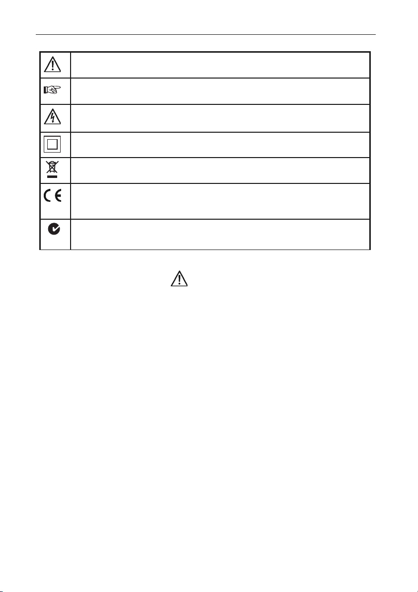
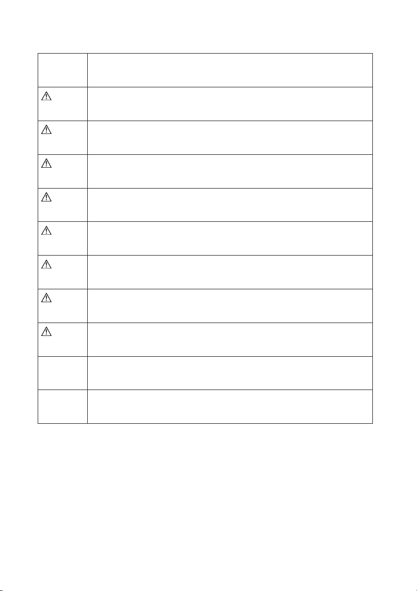
References marked on instrument or in instruction manual:
Warning of a potential danger, comply with instruction manual.
Reference. Please use utmost attention.
Caution! Dangerous voltage. Danger of electrical shock.
Continuous double or reinforced insulation complies with Category II IEC 61140.
Symbol for the marking of electrical and electronic equipment (WEEE Directive
2002/96/EC).
Conformity symbol, the instrument complies with the relevant Directives. It
complies with the EMC Directive (89/336/EEC). It also complies with the Low
Voltage Directive (73/23/EEC).
Conforms to relevant Australian standards.
N10140
WARNING
The instruction manual contains information and references necessary for safe operation
and maintenance of the instrument.
Prior to using the instrument (commissioning / assembly) the user is kindly requested to
thoroughly read the instruction manual and comply with it in all sections.
Failure to read the instruction manual or to comply with the warnings and references
contained herein can result in serious bodily injury or instrument damage.
5
Page 8

Introduction/ Contents
You have purchased a high quality measurement instrument of BEHA-AMPROBE GmbH which
will allow you to carry out measurement over a long time period.
The Amprobe EARTH-TEST is a handy test and measurement instrument for testing
Earthresistance. The Amprobe EARTH-TEST is characterised by the following features:
• Determination of earth resistance or specific earth resistance
• 2, 3, and 4-wire measurements possible
• Measurement of specific earth resistance measurement in compliance with the Wenner
method
• Measurement current of approx. 10mA
• Display and monitoring of both auxiliary earth and probe resistances
• Displays the actual test current to further enhance and control measurement quality
• Probe and auxiliary ground resistance up to 50 kΩ
• Noise voltage detection
• Two measurement frequencies for noise voltage suppression
• Automatically optimised measurement frequency selection
• Pre-selection of maximum admissible contact voltage: VL 25 or 50 V
• Large, visible LC-display
• Energy management
• Built in accordance with EN61557-5, IEC61557-5
Contents:
1 pc EARTH-TEST
1 pc test lead, black
1 pc test lead, blue
1 pc crocodile clamps, black
1 pc crocodile clamps, blue
1 pc carrying holster
6 pc batteries 1.5V Mignon Type IEC LR6 (Size AA)
1 pc instruction manual
Transport and Storage
• Please keep the original packaging for later transport, e.g. for calibration. Any transport
damage due to faulty packaging will be excluded from warranty claims.
• In order to avoid instrument damage, it is advised to remove batteries when not using the
instrument over a certain time period. However, should the instrument be contaminated
by leaking battery cells, you are kindly requested to return it to the factory for cleaning and
inspection.
• Instruments must be stored in dry and closed areas. In the case of an instrument being
transported in extreme temperatures, a recovery time of at least 2 hours is required prior
to instrument operation.
6
Page 9
Operator´s Safety
WARNING
The Amprobe EARTH-TEST has been designed and checked in accordance with the safety
regulations for Electronic test and Measurement and left our factory in a safe and perfect
condition. In order to maintain this condition and to ensure safe operation, the operator must
respect the references and warnings contained in this instruction manual.
• The respective accident prevention regulations established by the professional associations
for electrical systems and equipment must be strictly met at all times.
• Measurements in dangerous proximity of electrical installations are only to be executed
when instructed by a responsible electrical specialist, and never alone.
• Prior to usage, inspect instrument and test leads for external damage.Prior to any
operation, ensure that the connecting leads used and the instrument are both in perfect
condition.
• If the operator’s safety can no longer be guaranteed, the instrument is to be put out of
service and protected against use. The safety is no longer guaranteed, if theinstrument:
• shows obvious damage
• does not carry out the desired measurements
• has been stored for too long under unfavourable conditions
• has been subjected to mechanical stress during transport.
• The instrument may only be used within the operating ranges as specified in the technical
data section.
• Avoid any heating up of the instrument by direct sunlight to ensure perfect functioning and
long instrument life.
• The instrument may only be connected to voltage free earth connectors!
Appropriate Usage
WARNING
• The instrument may only be used under those conditions and for those purposes for which
it was built. For this reason, the safety references (chapter 3.0),as well as the technical data
including environmental conditions (chapter 15.0) must be followed at all times.
• The operational safety of the instrument is no longer guaranteedafter unauthorised
modifications or changes.
• Service and maintenance may only be carried out by an authorised service technician.
7
Page 10

General Information concerning Earth Measurement
The earth resistance is the resistance between reference earth and the connecting point of
the earthing system. The earthing system is required to bring each system parts and circuits
to a reference potential as close as possible to the reference earth. It is recommended to
perform earth measurements in systems as lightning protection, telecommunication and
tank parks.
The built-in earth measurement of the Amprobe EARTH-TEST is an earth resistance
measurement in accordance with the voltage/current measurement method. The power is
supplied by the built-in batteries. The earth resistance is determined in accordance with the
voltage/current measurement method. Earthing represents an essential part of a power
supply system. Earthing is required to bring the individual system parts and current circuits
to a common reference potential close to the reference earth. Earthing is also used to protect
systems from overvoltage or short-circuit currents.
The earth resistance must be of sufficiently low Ohm. The limit values are defined within
national or international standards. Earthing or earth resistance is comprised of the earth
conductor (equipotential bonding conductor or PE), the earth (foundation earth, rod earth,
band earth...), and the earth spreading resistance, i.e. the resistance between earth and
reference earth. A voltage funnel is formed around any earth depending on the earth shape
and the surrounding soil. Assuming that the soil is uniform throughout with a uniform
temperature as well as uniform humidity, the voltage funnels around the earth are of
concentric shape.
The lower the earth resistance, the smaller the voltage funnels. When determining the earth
resistance, the voltage drop is measured which has been generated by a known and constant
current applied to the earth resistance to be measured.
Influence on Measurement Accuracy
The instrument Amprobe EARTH-TEST offers the option to set a maximum measurement
voltage using the UL 25/50V key. The contact voltage limit for medical or agricultural
applications should be set to 25V. For all other applications, it is advised to set the limit to 50V.
The measurement current supplied by the instrument is above 10mA, thus ensuring a precise
measurement result. If, due to the total earthing resistance caused by the voltage which is
generated by the measurement current, the pre-set contact voltage limit of 25V is reached,
the measurement is only carried out at the current present at the contact voltage limit. If the
50V contact voltage limit has been selected the measurement current up to 50V is not limited.
For any measurement voltages exceeding 50V, the measurement current is limited to 3mA.
Thus, a precise measurement result at a sufficiently high measurement current is obtained,
even when encountering difficult measurement conditions, e.g. stony soils.
8
Page 11
Noise voltages present at ground connections may influence the measurement result. Noise
voltage influence is very low for the instrument EARTH-TEST. A precise filter suppresses all
interference whose frequencies are different with respect to the respective measurement
frequency. Together with the possibility to choose between two measurement frequencies,
best measurement results can be guaranteed. During automatic frequency selection mode,
EARTH-TEST selects the measurement frequency with the lowest, measured interference
voltage. Only use manual frequency selection, if the noise frequency is known. If noise
voltages are present influencing the measurement result in spite of the filter, this condition
is shown by displaying "Unoise". Further influence on measurement accuracy is emitted by
ratios RH/RE and RS/RE, or absolute value of RH and RS. If the ratio RH/RE (RS/RE) exceeds the
value 1000/1 (10000/1), the measurement accuracy indicated in the technical data section does
no longer apply for the Amprobe EARTH-TEST. This is caused by the fact that the voltage to
be measured only amounts to 1/1000 (1/10000) of the voltage present within the
measurement circuit. If the ratio RH/RE (RS/RE) becomes excessive, " Limit RH “RS“ is
shown in the display. The user should try to realise a better ground connection or earth rod
contact to the surrounding earth (e.g. inserting earth rods deeper into the ground, humid
earth or use earth rods parallel around earth rods).
Te chnical Terms:
Earth (E): The ground is a conductor within the earth or a
foundation being in conductive connection with the
earth (e.g. a foundation ground in concrete).
Earth probe (ES) Connector of earth rod next to the earth connecter.
Reference ground: An area of the earth that is sufficiently distant from the
respective ground such that no noticeable voltages,
caused by the grounding current, occur at any point
within this range.
Auxiliary earth electrode (H): Additional earth probe leading the measurement current
for measurement purposes.
Probe (S): An additional earth probe, preferably an earth rod,
which is used as a potential for the reference earth for
measurement purposes.
Spreading resistance of a earth: The resistance of the earth between earth and reference
earth.
9
Page 12

Product Description
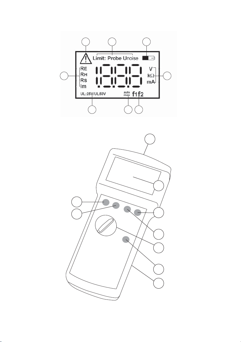
Indications in Display
(Also refer to display indications):
1) Symbol for Limit exceeding
2) Limit: Display at auxillary earth/ Probe-Error
Probe: Probe-Error
Unoise: external voltage
3) Battery indication
4) Indication of units, depending on the selection made (8)
5) Frequency indication
f1=127Hz/ f2=140Hz
6) Automatic/manual frequency selection
7) Contact voltage limit
8) Measurement indication
Control Elements
9) Connecting sockets for test leads:
Auxillary earth (H) black
Probe (S) yellow
Earth probe (ES) red
Earth (E) blue
10) LC Display
11) Key “UL“ for contact voltage: 50V/ 25V
12) Key “f1/f2“ for manual frequency selection:
f1=127Hz/ f2=140Hz
13) Measurement selection switch
14) Key “Start“
15) Battery case instrument (back side)
16) Key “auto/man“ automatic/ manual frequency selection
17) Key “Display“ for display of:
RE - earth resistance
RH - auxiliary earth resistance
RS - probe resistance
IM- measurement current
10
Page 13
1
2 3
15
17
16
4
7
56
9
10
11
12
11
13
14
15
Page 14
Commissioning
WARNING
• Measurements in dangerous proximity of electrical installations are only to be executed
when instructed by a responsible electrical specialist, and never alone.
• To perform this measurement the user requires the Earth Measurement Set (option).
• The instrument may only be connected to voltage-free earth connectors.
• Prior to inserting grounds or rods, check the soil for possible dangerous objects present
(pipes, conductors, etc.).
• If a voltage exceeding approx. 5V AC/DC is present at the test leads, the warning message
'Unoise' is displayed.
• To avoid faulty measurements, installed metal pipes, cables in the ground, or in open area
underground waterways or roots must be taken into account. Additionally, the specific
ground resistance is subject to seasonal weather-related variations.
12
Page 15
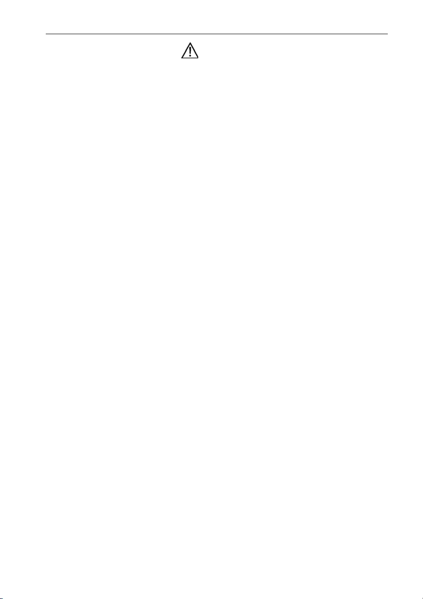
Earth Resistance Measurement (two-wire method)
The two-wire method consists of measuring the resistance between the earth under test and
a known earth. For this purpose, the PEN conductor of a TN system can be used, for example.
The resistance of the known earth connection has to be subtracted from the measurement
result. This measurement is also feasible in a densely populated or in sealed areas where rods
and auxiliary earth connections may not be installed.
E
PEN
RE
Figure 3: two-wire method
1) Connect earth to be tested with socket (E) and known earth with socket (H), also refer
to fig. 3
2) Turn the rotary switch (13) to the "2 pole" position.
3) Set contact voltage (11) by using key “UL“.
4) If required choose manual frequency selection by using key “auto/man” (16), and
select test frequency with key “f1/f2” (12).
5) Press key "Start" (14).
6) Read the measurement result from the display.
• Also refer to display indication
• After the measurement, selection can be made between display of earth resistance or
measurement current (IM) by using key “Display“(8), depending on the measurement result.
• Possibility to measure conventional resistance by using the grounding resistance
measurement range. For this purpose, connect test leads E and H to the DUT. Test current
is fed via lines E and H, measurement voltage is measured via E and H.
RPEN
13
Page 16
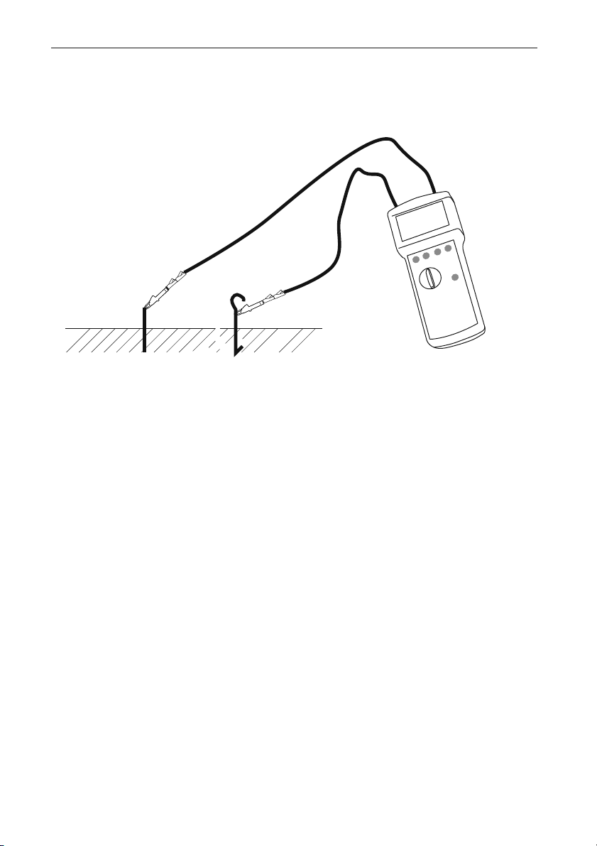
Earth Resistance Measurement (three-wire method)
• To perform this measurement the user requires the Earth Measurement Set (Cat. No.1048)
WARNING
The three-wire method consists of inserting two earth rods (one auxiliary earth and one
probe) into the soil, at a minimum distance of 20m. This layout can also be realized by
triangular shape. The test current is fed between auxiliary earth and earth. The voltage drop
between earth and probe is measured. The test lead resistance from measurement instrument
to earth is included in the measurement. This measurement is used to determine e.g. earth
resistance of foundation earths, building site earths and lighting protection earth
connections.
H
S
E
Figure 4: three-wire measurement
1) Locate earth rods for auxiliary ground, probe and ground, in one line if possible, as
described in figure 4. The layout can also be realized by triangular shape. Distance
between probe and earth, or probe and auxiliary earth must be at least 20 m. The test
leads should not be parallel to each other and should not cross to avoid couplings.
2) Connect test leads to earth rods acc. figure 4.
3) Select "3 pole" measurement by using measurement selection switch (13).
4) Set contact voltage (11) by using key “UL“ (14).
5) If required choose maunal frequency selection by using key “auto/man” (16), and
select test frequency with key “f1/f2” (12).
6) Press key “Start“ (14)
7) Read measurement result from display.
14
Page 17
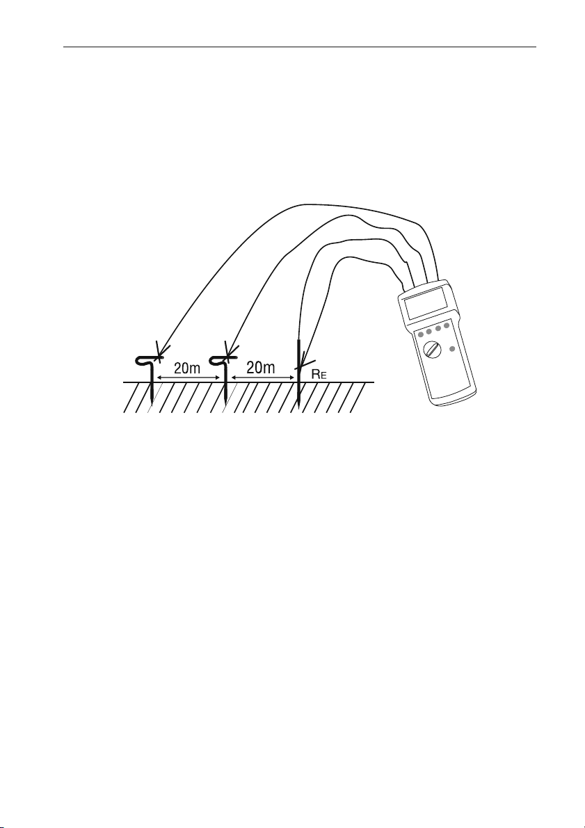
8) To verify the measurement, exchange the connections of probe and auxiliary earth or
move the earth rod for the probe approx. 1...2m towards the earth connector (or
afterwards towards the auxiliary earth) and measure again. If the instrument shows
similar measurement results for all three measurement layouts, the probe is located
outside the voltage funnel generated by earth and auxiliary earth in the reference
earth area.
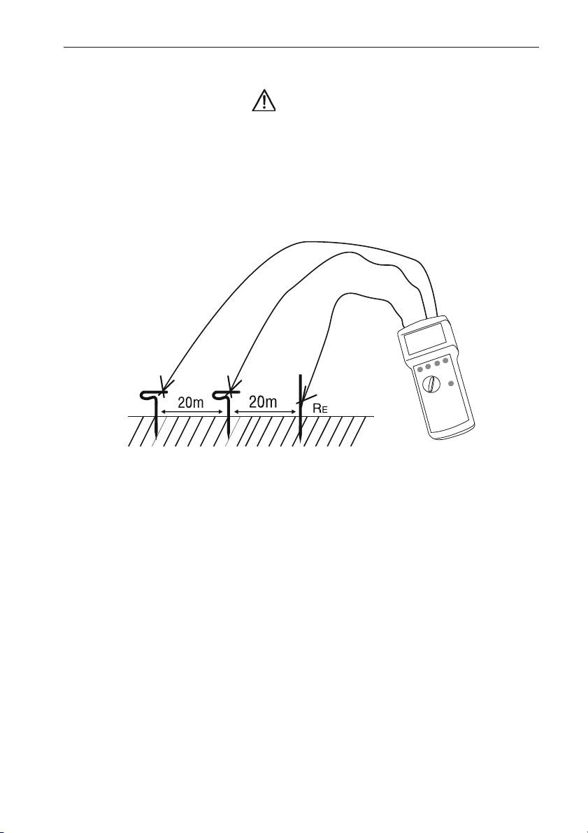
Are the measurement values not similar the probe could be located inside the voltage funnel.
To avoid this there are two possibilities:
A: increase the distance between earth and auxiliary earth
or,
B: position the earth rod for the probe to one point of the line outside the voltage
funnel, as shown in figure 5, and repeat the measurement.
Figure 5: Voltage funnel
• After the measurement, selection can be made between display of earth resitance (RE),
auxillary resistance (RS) and measurement current (IM) by using key “Display“ (8),
depending on the measurement result.
• The connection sequence must be respected. Otherwise the instrument will not be able to
carry out the measurement and indicates an error message:
• the display "Probe" indicates a connection error of S, E (interruptions, exchange
also with H or E)
• the "Limit IM" display indicates an interruption of the H connectors.
• Also refer to display indications
15
Page 18
Earth Resistance Measurement (four-wire method)
• To perform this measurement the user requires the Amprobe Earth Measurement Set
The four-wire measurement is applied instead of the three-wire measurement when dealing
with extremely low earth resistances and if the resistance of test lead between instrument
and earth connector interfere the measurement result.
Here, the earth to be measured is connected via the connectors E and ES, the measurement
selection switch is set to "4pol" and a measurement are performed as described.
H
S
ES
E
Figure 6: four-wire measurement
16
Page 19
Measurement of the Specific Earth resistance in accordance with
the 'Wenner' method
• To perform this measurement the user requires the Amprobe Earth Measurement Set
To calculate the spreading resistance of earths and earthing systems the specific earth
resistance must be determined. To calculate the specific earth resistance, the measured earth
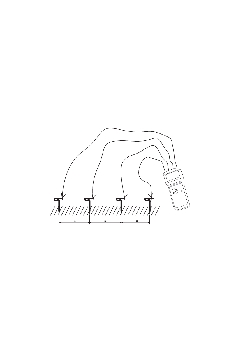
resistance is used in the formula: ρ = 2*π*a*RE.
This measurement is performed using four earth rods inserted into the soil to be tested in
one line at the same distance 'a' apart. The four earth rods are inserted into a depth of
maximum 1/5th of the distance 'a'.
The earth resistance is detected up to the depth of the distance 'a'. To avoid faulty
measurements metal pipes, cables in the earth, or in open areas under earth waterways, or
roots installed or located in parallel must be taken into account. Additionally, the specific
earth resistance is subject to seasonal weather-related variations.
H
S
ES
E
Figure 7: Specific Earth resistance measurement
1) Place the four earth rods for E, ES, S, H in one line, in accordance with Figure 7. The
distance between each probes must match the value used in the formula. Carefully
place the test leads making sure that the test leads are not parallel to each other and
do not cross to avoid coupling.
2) Connect test leads to earth rods according to figure 7.
3) Selct “4 pole“ measurement by using selection switch (13).
4) Set contact voltage by using key “UL“ (11).
5) If required choose manual frequency selection by using key “auto/man” (16), and
select test frequency with key “f1/f2” (12).
6) Press key "Start"(14), read measurement result on display.
17
Page 20
• After the measurement, selection can be made between display of earth resitance (RE),
auxillary resistance (RS) and measurement current (IM) by using key “Display“ (8),
depending on the measurement result.
• The connection sequence must be respected. Otherwise the instrument will not be able to
carry out the measurement and indicates an error message:
• the display "Probe" indicates a connection error of S, E (interruptions, exchange
also with H or E)
• the "Limit IM" display indicates an interruption of the H connection.
• The procedure is carried out a different locations and at respectively varying distances "a".
Thus, the composition of the soil for the desired area is examined. Here, a measurement
at larger distances "a" gives more details about the specific earth resistance in deeper
grounds.
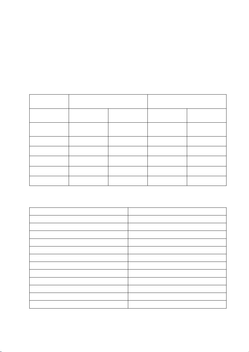
Ta ble 1:
Type of the
Ground
Earth Resistance
Bar Ground Connection
3m deep 5m deep 5m length 10m length
Earth Resistance
Flat Ground Connection
marshy
soil/swamp
arable land/clay 33 Ω 17 Ω 40 Ω 20 Ω
humid sandy soil 66 Ω 33 Ω 80 Ω 40 Ω
dry sandy soil 330 Ω 165 Ω 400 Ω 200 Ω
stony soil 1000 Ω 500 Ω 1200 Ω 60 Ω
concrete1:5 160 Ω 80 Ω
References to evaluate measurement results (in compliance with DIN VDE 0413
Ta ble 2:
Required max. Permissable Resistance Maximum Displayed Test Value
0.3 Ω 0.18 Ω
0.4 Ω 0.28 Ω
0.5 Ω 0.37 Ω
0.6 Ω 0.46 Ω
0.7 Ω 0.56 Ω
0.8 Ω 0.65 Ω
0.9 Ω 0.75 Ω
1.0 Ω 0.84 Ω
2. 0 Ω 1.84 Ω
3.0 Ω 2.79 Ω
4.0 Ω 3.73 Ω
5.0 Ω 4.67 Ω
10 Ω
5 Ω 12 Ω 6 Ω
Example for Table 2: Required max. permissable resistance 1Ω.
Maximum displayed test value on EARTH-TEST 0,84 Ω.
18
Page 21
Display Indications
Message Cause
Reference to exeeding the limit of a measurement value
Probe
Limit
I
M
Unoise
Limit
RH
Limit
RS
Limit
RE
Limit
BatterySymbol
Batt-Symbol
is
blinking
Interruption / exchange probe(S) - earth probe (ES) (at 4 pole measurement)
Interruption / exchange probe (S) - earth (E) (at 3 pole measurement)
Interruption auxillary earth (H) - earth (E) (at 2 pole measurement)
Interruption auxillary earth (H) - earth (E) (at 4/3 pole measurement)
External voltage has exceeded admissible value,
Measurement values do not longer correspond to the specifications!
Measurement value RH > 50 kΩ
or RH > 1000 RE
measurement values do not longer correspond to specifications
Measurement value probe resistance (RS) > 50 kΩ
or probe resistance (RS) > 10000 x RE
Measurement values do not longer correspond to specifications!
Measurement value earth resistance (RE) > 2 kΩ (at 4/3 pole measurement)
Displayed measurement values for RH, RS are then RH+RE,RS+RE !
Measurement value R > 2kΩ (at 2 pole measurement)
Batteries are nearly empty. must be changed.
Measurement values do not longer correspond to specifications!
Batteries are complete empty. measurement no longer possible!
19
Page 22
Energy Management
Approximately 5 minutes after last key operation, the instrument switches off automatically
(auto-power-off). To switch the instrument on again, turn rotary switch from the "OFF"
position to the desired function.
If the batteries are almost completely discharged, the battery symbol (3) appears. The
instrument continues functioning without necessarily respecting the specifications.
If the batteries continue to be used and discharged, the instrument switches off at a point
when the minimum battery voltage level is reached and may not be switched on again.
Maintenance
When using the instrument in compliance with the instruction manual, no special
maintenance is required.
Cleaning
If the instrument is dirty after daily usage, it is advised to clean it by using a damp cloth and
a mild household detergent.
Prior to cleaning, ensure that the instrument is switched off and disconnected all external
circuits.
• Never use acid detergents or dissolvants for cleaning.
Battery Replacement
WARNING
• Prior to battery replacement, disconnect the instrument from all connected measurement
circuits.
• Only use batteries in compliance with the specifications of the technical data section, 1.5 V
type IEC LR6 (Size AA/ Mignon) .
• Never try to disassemble battery cells. Never throw a battery into fire as this could lead to
an explosion. Never expose batteries to humidity
• Please consider your environment when you dispose of your used batteries or accumulators.
They belong in a rubbish dump for hazardous waste. In most cases, the batteries can be
returned to their point of sale.
• Please, comply with the appropriate regulations concerning the return, recycling and
disposal of used batteries and accumulators.
• If an instrument is not used over an extended time period, the batteries must be removed.
Should the instrument be contaminated by leaking battery cells, the instrument has to be
returned for cleaning and inspection to the factory.
20
Page 23
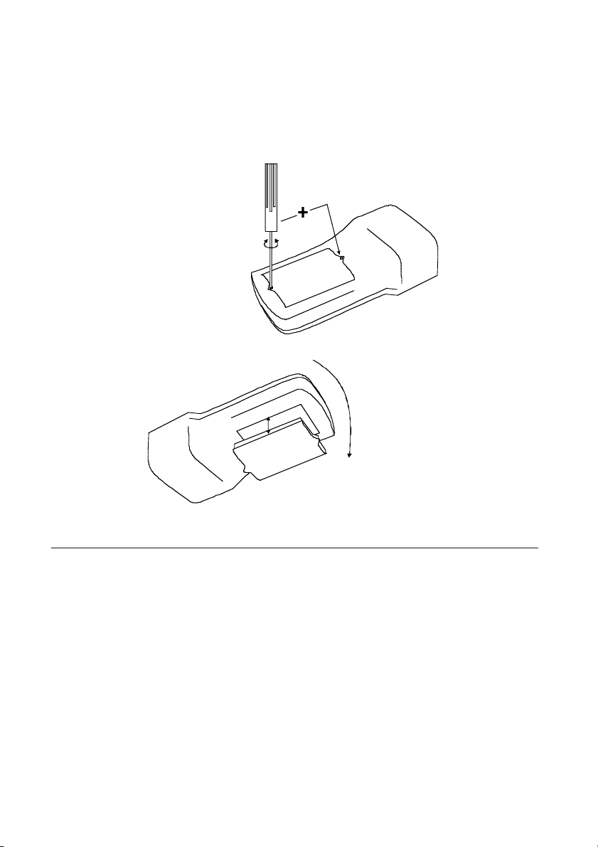
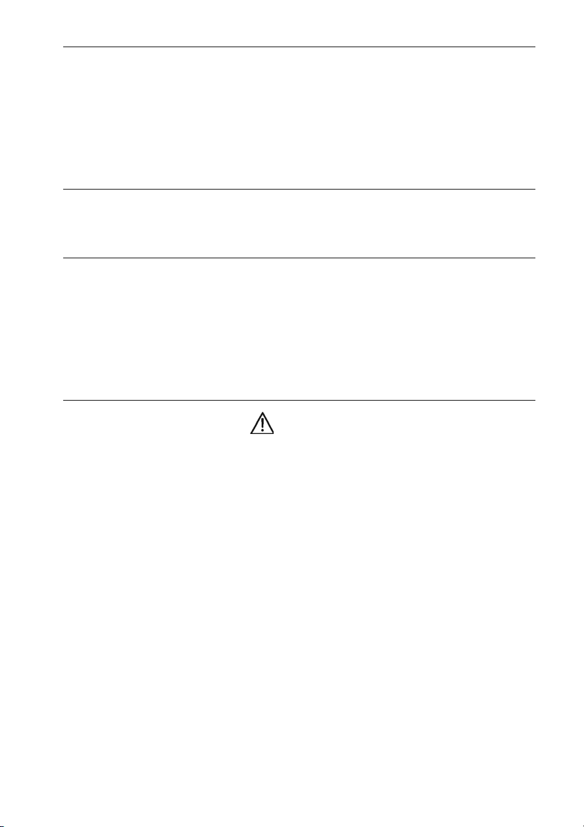
1) If the battery symbol (3) appears in the display, the batteries must be replaced..
2) Switch off the instrument via the measurement slection switch.
3) Loosen the screws on the instrument rear.
4) Lift the battery case cover (by slightly hitting the instrument in the palm of your hand).
5) Remove the discharged batteries.
6) Insert new batteries and ensure the correct polarity is respected.
7) Replace the battery case cover and retighten the screws.
8) The instrument is now ready for further measurements.
Calibration Interval
We suggest a calibration interval of one year. If the instrument is used very often or if it is used
under rough conditions we recommend shorter intervals. If the instrument is used few times
only the calibration interval can be extended on to 3 years.
21
Page 24

Technical Data
Display: 3 digit LCD, 1999 digit
Duration of measurement: 3-5s
Measurement principle: current-voltage measurement principle in accordance with
EN61557-5
Measurement voltage: 25V/ 50V selection
Current/power consumption: approx. 10mA/ 0,1W max. 500mA briefly, during measurement
Measurement current: max. 12mA
Frequency (f1/ f2): 127Hz/ 140Hz, selectable
Measurement method: 2 pole/ 3 pole/ 4 pole
Range Tolerance
RE: 0.05 - 2.00 Ohm ±(4% + 0.1 Ohm) ±(6% + 0.1 Ohm)*
RE: 2.00 - 1999 Ohm ±(4% + 2 Digit) ±(6% + 3 Digit)*
RH, RS: 0.1 - 50 kOhm ±(10% + 3 Digit)*
IM: 0.1 - 13mA ±(10% + 3 Digit)*
*operating error
Nominal use range:
Correct polarity: for 3/4 pole measurements
Noise voltage: 0...5V, max. 10% of measurement voltage
aux. earth (RH), probe resis. (RS): max. 50 kOhm
Ratio RH/ RE: max. 1000/1
Ratio RS/ RE: max. 10000/1
Earth resistance (RE): max. 2 kOhm
Reference range:
Correct polarity: for 3/4 pole measurements
Noise voltage: 0 V
aux. earth (RH),
probe resis. (RS) 0 Ohm
Earth resistance (RE): max. 2 kOhm
Auto power off after approx. 5 min
Power supply 6 x 1.5 V Type IEC LR6 (Mignon/Size AA)
Low Bat at 6.6 V ±5 % (OFF at 6.1V ±5 %)
Battery life approx. 1 year for normal use
Dimensions (LxWxD) 235x105x68 mm
Weight approx. 640g (inc. 6 x batteries)
22
Page 25

Environmental Conditions
Temperature range /
humidity 0°C...40°C / max. 80% at -10°C...40°C
Reference temperature
range: +17°C...+27°C
Storage temperature range -20°C...+60°C
Casing protection class II
Built in accordance with IEC 61557-5, DIN VDE 0413-5, EN 61557-5,
Overvoltage category CAT III / 300V against ground
Pollution degree 2
Protection class: II
Protection degree IP50
Height above MSL. up to 2000m
23
Page 26

Subject to technical changes without notice!
11/2007 PAEB30872261
24
Page 27

EARTH-TEST
Series
Earth-Resistance Tester
Bedienungshandbuch
Anleitung
©2007 Amprobe
Page 28

Inhalt ................................................................................................................................Seite
Beschränkte Gewährleistung und Haftungsbeschränkung ............................................3
Reparatur ..........................................................................................................................3
Auf dem Gerät oder in der Bedienungsanleitung vermerkte Hinweise: ........................5
Einleitung / Lieferumfang ................................................................................................6
Transport und Lagerung....................................................................................................6
Sicherheitsmaßnahmen ....................................................................................................7
Bestimmungsgemäße Verwendung..................................................................................7
Allgemeines zur Erdmessung ..........................................................................................8
Einflüsse auf die Messgenauigkeit....................................................................................8
Begriffe ..............................................................................................................................9
Bedienelemente und Anzeigen ........................................................................................10
Durchführen von Messungen............................................................................................12
Erdungswiderstandsmessung (Zweileitermethode) ......................................................13
Erdungswiderstandsmessung (Dreileitermethode) ........................................................14
Erdungswiderstandsmessung (Vierleitermethode) ........................................................16
Spezifischer Erdwiderstandsmessung
(Vierleitermethode nach Wenner) ..................................................................................17
Anzeigen / Fehlermeldungen............................................................................................19
Energiemanagement ........................................................................................................20
Wartung ............................................................................................................................20
Reinigung ..........................................................................................................................20
Batteriewechsel..................................................................................................................20
Kalibrierintervall................................................................................................................21
Technische Daten ..............................................................................................................22
2
Page 29

Beschränkte Gewährleistung und Haftungsbeschränkung
Es wird gewährleistet, dass dieses Amprobe-Produkt für die Dauer der gesetzlichen Gewährleistungspflicht ab dem Kaufdatum frei von Material- und Fertigungsdefekten ist. Diese Gewährleistung erstreckt sich nicht auf Sicherungen, Einwegbatterien oder Schäden durch Unfälle, Nachlässigkeit, Missbrauch, Änderungen oder abnormale Betriebsbedingungen bzw.
unsachgemäße Handhabung. Die Verkaufsstellen sind nicht dazu berechtigt, diese Gewährleistung im Namen von Amprobe zu erweitern. Um während der Gewährleistungsperiode Serviceleistungen zu beanspruchen, das Produkt mit Kaufnachweis an ein autorisiertes AMPROBE Service-Center oder an einen Amprobe-Fachhändler/-Distributor einsenden. Einzelheiten
siehe Abschnitt „Reparatur“ oben. DIESE GEWÄHRLEISTUNG STELLT DEN EINZIGEN UND ALLEINIGEN RECHTSANSPRUCH AUF SCHADENERSATZ DAR. ALLE ANDEREN GEWÄHRLEISTUNGEN - VERTRAGLICH GEREGELTE ODER GESETZLICHE VORGESCHRIEBENE - EINSCHLIESSLICH
DER GESETZLICHEN GEWÄHRLEISTUNG DER MARKTFÄHIGKEIT UND DER EIGNUNG FÜR EINEN
BESTIMMTEN ZWECK, WERDEN ABGELEHNT DER HERSTELLER ÜBERNIMMT KEINE HAFTUNG
FÜR SPEZIELLE, INDIREKTE, NEBEN- ODER FOLGESCHÄDEN ODER VERLUSTE, DIE AUF BELIEBIGER URSACHE ODER RECHTSTHEORIE BERUHEN. Weil einige Staaten oder Länder den Ausschluss oder die Einschränkung einer implizierten Gewährleistung sowie von Begleit- oder Folgeschäden nicht zulassen, ist diese Gewährleistungsbeschränkung möglicherweise für Sie nicht
gültig.
Reparatur
Zu allen Geräten, die zur Reparatur oder Kalibrierung im Rahmen der Garantie oder
außerhalb der Garantie eingesendet werden, muss folgendes beigelegt werden: Name des
Kunden, Firmenname, Adresse, Telefonnummer und Kaufbeleg. Zusätzlich bitte eine kurze
Beschreibung des Problems oder der gewünschten Wartung sowie die Messleitungen dem
Messgerät beilegen. Die Gebühren für Reparaturen außerhalb der Garantie oder für den Ersatz von Instrumenten müssen als Scheck, Geldanweisung, Kreditkarte (Kreditkartennummer
mit Ablaufdatum) beglichen werden oder es muss ein Auftrag an AMPROBE formuliert werden.
Bitte die nachfolgende Garantieerklärung lesen und die Batterie prüfen, bevor Reparaturen
angefordert werden. Während der Garantieperiode können alle defekten Geräte zum Umtausch gegen dasselbe oder ein ähnliches Produkt an den AMPROBE-Distributor gesendet werden. Ein Verzeichnis der zuständigen Distributoren ist im Abschnitt „Where to Buy“ (Verkaufsstellen) auf der Website www.amprobe.eu zu finden. Darüber hinaus können in den USA
und in Kanada Geräte an ein AMPROBE Service-Center (Adresse siehe weiter unten) zur Reparatur oder zum Umtausch eingesendet werden.
3
Page 30

Reparaturen und Austausch außerhalb der Garantie
USA und Kanada Für Reparaturen außerhalb der Garantie in den Vereinigten Staaten und in
Kanada werden die Geräte an ein AMPROBE Service-Center gesendet. Auskunft über die derzeit geltenden Reparatur- und Austauschgebühren erhalten Sie von AMPROBE oder der Verkaufsstelle.
In USA In Canada
Amprobe Test Tools Amprobe Test Tools
Everett, WA 98203 Mississauga, ON L4Z 1X9
Tel: 877-993-5853 Tel: 905-890-7600
Fax: 425-446-6390 Fax: 905-890-6866
Reparaturen und Austausch außerhalb der Garantie - Europa
Geräte außerhalb der Garantie können durch den zuständigen AMPROBE- Distributor gegen
eine Gebühr ersetzt werden. Ein Verzeichnis der zuständigen Distributoren ist im Abschnitt
„Where to Buy“ (Verkaufsstellen) auf der Website www.amprobe.eu zu finden.
Korrespondenzanschrift für Europa*
BEHA-AMPROBE GmbH
In den Engematten 14
79286 Glottertal
Germany
Tel.: +49 (0) 7684 8009 - 0
Fax: +49 (0) 7684 8009 - 410
www.amprobe.de
info@amprobe.de
4
Page 31

Auf dem Gerät oder in der Bedienungsanleitung vermerkte
Hinweise:
Warnung vor einer Gefahrenstelle. Bedienungsanleitung beachten.
Hinweis Bitte unbedingt beachten.
Vorsicht! Gefährliche Spannung, Gefahr des elektrischen Schlages.
Durchgängige doppelte oder verstärkte Isolierung entsprechend Klasse II IEC
61140.
Kennzeichnung elektrischer und elektronischer Geräte (WEEE Richtlinie
2002/96/EG).
Konformitätszeichen, bestätigt die Einhaltung der gültigen Richtlinien. Die EMVRichtlinie (89/336/EWG)werden eingehalten. Die Niederspannungsrichtlinie
(73/23/EWG) wird ebenfalls eingehalten.
Übereinstimmung mit den relevanten australischen
N10140
Normen
WARNHINWEIS
Die Bedienungsanleitung enthält Informationen und Hinweise, die zu einer sicheren Bedienung und Nutzung des Gerätes notwendig sind.
Vor der Verwendung (Inbetriebnahme ) des Gerätes ist die Bedienungsanleitung aufmerksam
Wird die Anleitung nicht beachtet oder sollten Sie es versäumen, die Warnungen und Hinweise zu beachten, können ernste Verletzungen des Anwenders bzw. Beschädigungen des
Gerätes eintreten.
5
Page 32

Einleitung / Lieferumfang
Das AMPROBE EARTH-TEST ist ein handliches Prüfgerät zur Bestimmung des Erdungswiderstandes. Das Messgerät wurde gemäß den gültigen Vorschriften gebaut und gewährleistet
ein sicheres und zuverlässiges Arbeiten.
Das AMPROBE EARTH-TEST zeichnet sich durch folgende Punkte aus:
• Bestimmung des Erdungswiderstandes oder des spezifischen Erdwiderstandes
• 2-, 3- und 4-Leiter-Messung möglich
• Messung nach der Wenner-Methode
• Messstrom größer 10mA
• Messung und Überwachung des Hilfserderwiderstandes und der Sondenwiderstände
• Anzeige des aktuellen Messstroms zur Kontrolle der Messunsicherheit
• Sonden- und Hilfserderwiderstände bis 50 kΩ
• Störspannungserkennung
• Zwei Messfrequenzen (127/140Hz) zur Störspannungsuntedrückung
• Automatisch optimierte Messfrequenzwahl
• Vorwahl der max. zulässigen Berührungsspannung: UL 25/50 V
• Großes, übersichtliches Display
• Energiemanagement
• Gebaut nach DIN VDE 0413 Teil 5, EN61557-5, IEC61557-5
Im Lieferumfang sind enthalten:
1 St. EARTH-TEST
1 St. Messleitung rot
1 St. Messleitung blau
1 St. Krokodil-Klemme rot
1 St. Krokodil-Klemme blau
1 St. Bereitschaftstasche
6 St. Batterie 1,5V Mignon IEC LR6
1 St. Bedienungsanleitung
Transport und Lagerung
Bitte bewahren Sie die Originalverpackung für eine spätere Versendung, z.B. zur Kalibration,
auf. Transportschäden aufgrund von mangelhafter Verpackung sind von der Garantie ausgeschlossen.
Um Beschädigungen zu vermeiden, sollten die Batterien entnommen werden, wenn das Messgerät über einen längeren Zeitraum nicht benutzt wird. Sollte es dennoch zu einer Verunreinigung des Gerätes durch ausgelaufene Batteriezellen gekommen sein, muss das Gerät zur
Reinigung und Überprüfung ins Werk eingesandt werden.
Die Lagerung des Gerätes muss in trockenen, geschlossenen Räumen erfolgen. Sollte das Gerät
bei extremen Temperaturen transportiert worden sein, benötigt es vor dem Einschalten eine
Aklimatisierung von mindestens 2 Stunden.
6
Page 33

Sicherheitsmaßnahmen
WARNHINWEIS
Das AMPROBE EARTH-TEST wurde gemäß den Sicherheitsbestimmungen für elektronische
Mess- und Prüfgeräte gebaut und hat das Werk in sicherheitstechnisch einwandfreiem Zustand
verlassen. Um diesen Zustand zu erhalten, muss der Anwender die Sicherheitshinweise in dieser Anleitung beachten.
• Bei sämtlichen Arbeiten müssen die jeweils gültigen Unfallverhütungsvorschriften der gewerblichen Berufsgenossenschaften für elektrische Anlagen und Betriebsmittel beachtet
werden.
• Messungen in gefährlicher Nähe elektrischer Anlagen sind nur nach Anweisung einer verantwortlichen Elektrofachkraft und nicht alleine durchzuführen.
• Überprüfen Sie das Messgerät und die verwendeten Anschlussleitungen vor jedem Einsatz
auf äußerliche Schäden. Vergewissern Sie sich, dass das Messgerät und die verwendeten Anschlussleitungen in einwandfreiem Zustand sind. Das Messgerät darf nicht mehr benutzt
werden, wenn eine oder mehrere Funktionen ausfallen oder keine Funktionsbereitschaft erkennbar ist.
• Wenn die Sicherheit des Bedieners nicht mehr gewährleistet ist, muss das Gerät außer Betrieb gesetzt und gegen ungewolltes Benutzen gesichert werden. Dies ist der Fall, wenndas
Gerät: • offensichtliche Beschädigungen aufweist
• die gewünschten Messungen nicht mehr durchführt
• zu lange unter ungünstigen Bedingungen gelagert wurde
• während des Transportes mechanischen Belastungen ausgesetzt war.
• Das Gerät darf nur in dem unter “Technische Daten” spezifizierten Betriebs- und Messbe-
reichen eingesetzt werden.
• Vermeiden Sie eine Erwärmung der Geräte durch direkte Sonneneinstrahlung. Nur so kann
eine einwandfreie Funktion und eine lange Lebensdauer gewährleistet werden.
• Das Messgerät darf nur an spannungsfreie Erder angeschlossen werden.
Bestimmungsgemäße Verwendung
WARNHINWEIS
• Das Gerät darf nur in den unter “Technische Daten” spezifizierten Betriebs- und Messbe-
reichen eingesetzt werden.
• Die Betriebssicherheit ist bei Modifizierung oder Umbauten nicht mehr gewährleistet.
• Wartungs- oder Kalibrierarbeiten dürfen nur von unserem Werkspersonal durchgeführt
werden.
7
Page 34

Allgemeines zur Erdmessung
Der Erdungswiderstand ist der Widerstand zwischen der Bezugserde und dem Anschlusspunkt
der Erdungsanlage. Die Erdungsanlage wird benötigt, um die einzelnen Anlagenteile und
Stromkreise auf ein Bezugspotential möglichst nahe der Bezugserde zu bringen. Erdungsmessungen sind in Anlagen, die Schutz durch Abschaltung besitzen, sowie in Blitzschutz-,
Fernmelde- und Tankanlagen vorgeschrieben.
Bei der im AMPROBE EARTH-TEST eingebauten Erdungsmessung handelt es sich um eine Erdwiderstandsmessung nach dem Strom/Spannungsverfahren. Die Stromversorgung wird durch
die eingebauten Batterien sichergestellt. Die Erdwiderstände werden mit dem Strom-Spannungs-Messverfahren ermittelt. Die Erdung ist ein wesentlicher Teil einer Stromversorgungsanlage. Sie ist erforderlich, um die einzelnen Anlagenteile und Stromkreise auf ein gemeinsames Bezugspotential, nahe der Bezugserde, zu bringen. Erdungen werden auch verwendet, um
Anlagen vor Überspannungen oder Kurzschlussströmen zu schützen.
Die Erdungswiderstände müssen hinreichend niederohmig sein, Richtwerte sind in den DIN
VDE-Bestimmungen festgelegt. Die Erdung bzw. der Erdungswiderstand besteht aus der Erdungsleitung (Potentialausgleichsleiter oder PE), dem Erder (Fundamenterder, Staberder,
Banderder..) und dem Erdausbreitungswiderstand. Das ist der Widerstand zwischen dem Erder
und der Bezugserde.
Um jeden Erder bildet sich ein Spannungstrichter, der von der Form des Erders und dem umgebenden Erdreich abhängig ist. Geht man von einem gleichartig beschaffenen Erdreich aus, mit
gleicher Temperatur und gleicher Feuchtigkeit, bilden sich um den Erder Spannungstrichter von
konzentrischer Form.
Je niederohmiger der Erdwiderstand ist, desto kleiner sind die Spannungstrichter. Gemessen
wird bei der Erdwiderstandsmessung der Spannungsfall, erzeugt von einem bekannten konstanten Strom über den zu messenden Erdwiderstand.
Einflüsse auf die Messgenauigkeit
Das EARTH-TEST bietet die Möglichkeit , eine maximale Messspannung mit der Taste UL 25/50V
einzustellen. Das Berührungsspannungslimit sollte im medizinischen bzw. landwirtschaftlichen Bereich auf 25V, bei allen anderen Anwendungen auf 50 V eingestellt werden.
Das Gerät liefert einen Messstrom von mehr als 10mA, dadurch wird ein genaues Messergebnis
gewährleistet. Wenn aufgrund des Gesamterdungswiderstandes die durch den Messstrom
entstehende Spannung das gewählte Berührungsspan- nungslimit von 25V erreicht, wird nur
mit dem Strom gemessen, der bei dem Berührungsspannungslimit fließt. Wenn das gewählte Berührungsspannungslimit 50V ist, wird der Messstrom bis 50V nicht begrenzt, bei Messspannungen über 50V wird der Messstrom auf 3mA begrenzt. Dadurch wird auch bei schwierigen Messbedingungen, z.B. im steinigen Boden, mit einem ausreichenden Messstrom ein
genaues Messergebnis gewährleistet.
An den Erdern anliegende Störspannungen können das Messergebnis beeinflussen. Der Einfluß von Störspannungen ist beim EARTH-TEST sehr gering. Ein präziser Filter unterdrückt alle
Störungen, deren Frequenzen verschieden zu der jeweiligen Messfrequenz sind. In Verbin-
dung mit der Möglichkeit, aus zwei Messfrequenzen zu wählen, werden auch bei hohen Störfeldern gute Messergebnisse garantiert.
8
Page 35

Bei der automatischen Frequenzwahl wählt das EARTH-TEST diejenige Messfrequenz, bei der
die geringsten Störspannungen gemessen werden. Nur wenn die Störfrequenz bekannt ist,
sollte die Messfrequenz manuell gewählt werden. Falls einmal so hohe Störspannungen anliegen, die trotz Filter das Messergebnis beeinflussen, wird dies im Display durch “Unoise” angezeigt. Ein weiterer Einfluß auf die Messgenauigkeit haben die Verhältnisse von Hilfserder
bzw. Sondenwiderstände zum Erdungswiderstand (RH/RE bzw. RS/RE) und die absoluten Werte
der Hilfserder bzw. Sondenwiderstände (RH/RS). Wenn das Verhältnis RH/RE (bzw. RS/RE) den
Wert 1000/1 (bzw. 10000/1) überschreitet, dann kann das EARTH-TEST nicht mehr so genau
messen, wie in den techn. Daten angegeben. Dies liegt daran, dass dann die zu messende Spannung nur 1/1000 (1/10000) der im Messkreis anliegenden Spannung ist. Wenn die Hilfserder
und Sondenwiderstände zu groß werden, wird dies im Display mit “ Limit RH” angezeigt.
Es sollte dann versucht werden, einen besseren Kontakt der Erder bzw. Erdspieße zum Erdreich zu bekommen (Erdspieße z.B. tiefer einschlagen, Erdreich anfeuchten), mehrere Spiesse
parallel verwenden.
Begriffe
Erder (E): Der Erder ist ein Leiter, der in die Erde oder in einem Fun-
dament eingebettet ist und mit der Erde in leitender Ver-
bindung steht (beispielsweise ein Fundamenterder in
Beton).
Erder Sonde (ES): Anschluß der dem Erder nächstliegenden Sonde.
Bezugserde: Ein Bereich der Erde, der von dem zugehörigen Erder so-
weit entfernt ist, dass zwischen beliebigen Punkten dieses Bereiches keine vom Erdungsstrom herrührenden
merklichen Spannungen auftreten.
Hilfserder (H): Zusätzlicher Erder, über den der zum Zwecke der Messung
benötigte Messstrom fließt.
Probe (S): Ein zusätzlicher Erder, vorzugsweise ein Erdspieß, der zum
Zweck der Messung als Potentialabgriff für die Bezugserde dient.
Ausbreitungswiderstand eines
Erders:
Der Widerstand des Erdreiches zwischen dem Erder und
der Bezugserde.
9
Page 36

Bedienelemente und Anzeigen
Anzeigen im LC-Display :
(siehe auch Anzeigen/ Fehlermeldungen)
1) Symbol für Grenzwertüberschreitung
2) Limit: Anzeige bei Hilfserder/Sondenfehler
Probe: Sondenfehler
Unoise: Fremdspannung
3) Batteriezustandsanzeige
4) Einheitenanzeige abhängig von der Messgrösse (8)
5) Frequenzanzeige (f1=127Hz/ f2=140Hz)
6) automatische/manuelle Frequenzwahl
7) Berührungsspannungsgrenzwert
8) Messgrößenanzeige
Bedienelemente
9) Anschlußbuchsen für die Messleitungen:
Hilfserder H) schwarz
Sonde (S) gelb
Erder-Sonde (ES) rot
Erder (E) blau
10) LC Display
11) Taste UL für Berührungsspannung: 50V/ 25V
12) Taste f1/f2 für manuelle Frequenzwahl(f1=127Hz/ f2=140Hz)
13) Messartwahlschalter
14) Taste “Start”
15) Batteriefach auf Geräterückseite
16) Taste auto/man für automatische/ manuelle Frequenzwahl (siehe auch 4.1)
17) Taste “Anzeige” zur Auswahl der Messgrößenanzeige im Display
RE - Erdungswiderstand
RH - Hilfserderwiderstand
RS - Sondenwiderstand
IM- Messstrom
10
Page 37

1
2 3
15
17
16
4
7
56
9
10
11
12
11
13
14
15
Page 38

Durchführen von Messungen
WARNHINWEIS
• Messungen in gefährlicher Nähe elektrischer Anlagen sind nur nach Anweisung einer ver-
antwortlichen Elektrofachkraft und nicht alleine durchzuführen.
• Zur Durchführung der Erdungsmessung mit Erdspießen (Hilfserder/Sonde) wird das AM-
PROBE Zubehör-Set (Best.-Nr. 1048) benötigt.
• Das Messgerät darf nur an spannungsfreie Erder angeschlossen werden.
• Vor dem Einschlagen der Erder oder Sonden ist der Untergrund auf evtl. vorhandene ge-
fährliche Objekte (Rohre, Leitungen, usw.) zu untersuchen.
• Liegt eine Spannung größer ca. 5V AC/DC an den Messleitungen an, so wird die Warnmel-
dung 'Unoise' angezeigt.
• Um Fehlmessungen zu vermeiden, muss auf parallel zur Messanordnung verlegte metalli-
sche Rohre, Erdkabel oder im freien Gelände auf Wasseradern oder Wurzeln geachtet werden. Außerdem ist der spezifische Erdungswiderstand witterungsbedingten jahreszeitlichen Schwankungen unterworfen.
12
Page 39

Erdungswiderstandsmessung (Zweileitermethode)
Bei der Zweileitermessung wird der Widerstand zwischen dem zu messenden Erder und einem
bekannten Erder gemessen, hier kann z.B. der PEN-Leiter eines TN-Systems benutzt werden. Vom
Messergebnis ist der Widerstand des bekannten Erders abzuziehen. Diese Messung lässt sich
auch in einem dicht bebauten oder in versiegelten Gebieten durchführen, wo Sonden und Hilfserder nicht gesetzt werden können.
E
PEN
RE
Bild 3: Messprinzip, zweipolige Messung:
1) Zum messenden Erder mit der Buchse (E) und bekannter Erder mit der Buchse (H)
verbinden siehe auch Bild 3.
2) Drehen Sie den Messartwahlschalter (13) in Stellung “2 pol”.
3) Stellen Sie die gewünschte Berührungsspannung mit der Taste “UL” (11) ein.
4) Falls gewünscht stellen Sie die manuelle Frequenzwahl mit der Taste “auto/man” (16)
und die Messfrequenz mit der Taste “f1/f2” (12) ein.
5) Taste “Start” (14) drücken.
6) Lesen Sie das Messergebnis vom Display ab.
• siehe auch Anzeige / Fehlermeldungen
• Nach erfolgter Messung kann je nach Messergebnis mit der Taste “Anzeige” (17) zwischen
den Anzeigen für Erdungswiderstand und Messstrom (IM) gewählt werden.
• Mit dem Messbereich “2pol” können auch herkömmliche Widerstände gemessen werden.
Verbinden Sie dazu am Prüfling die Leitungen E und H. Der Prüfstrom fließt über die Leitungen E und H, die Messspannung wird ebenfalls über E und H gemessen.
RPEN
13
Page 40

Erdungswiderstandsmessung (Dreileitermethode)
• Zur Durchführung dieser Messung benötigen Sie das AMPROBE Zubehör-Set (option)
WARNHINWEIS
Bei der Dreileitermessung werden 2 Erdspieße (ein Hilfserder und eine Sonde) im Abstand
von mindestens 20m gesetzt. Diese Anordnung kann auch in Dreiecksform erfolgen. Der Messstrom wird zwischen Hilfserder und Erder eingespeist und der Spannungsfall zwischen Erder
und Sonde gemessen. Der Widerstand der Messleitung vom Messgerät zum Erder wird mitgemessen. Mit dieser Messung können z.B. die Erdungswiderstände von Fundament-, Baustellen- und Blitzschutzerdern ermittelt werden.
H
S
E
Bild 4: dreipolige Messung
1) Ordnen Sie die Erdspieße für Hilfserder und Sonde, wie in Bild 4 gezeigt an. Diese
Anordnung kann auch in Dreiecksform erfolgen. Der Abstand zwischen Sonde und
Erder bzw. Sonde und Hilfserder muss mindestens 20m betragen. Legen Sie die
Leitungen sorgfältig aus und achten Sie darauf, dass die Leitungen möglichst nicht
parallel nebeneinander liegen und sich nicht kreuzen, um Einkopplungen zu
vermeiden.
2) Verbinden Sie die Messleitungen mit den Erdspießen gemäß Bild 4.
3) Drehen Sie den Messartwahlschalter (13) in Stellung “3 pol”.
4) Stellen Sie die gewünschte Berührungsspannung mit der Taste “UL” (11) ein.
5) Falls gewünscht stellen Sie die manuelle Frequenzwahl mit der Taste “auto/man” (16)
und die Messfrequenz mit der Taste “f1/f2” (12) ein.
6) Taste “Start” (14) drücken.
7) Lesen Sie das Messergebnis vom Display ab.
14
Page 41

8) Zur Kontrolle der Messung vertauschen Sie die Anschlüsse für Sonde und Hilfserder
oder Sie versetzen den Erdspieß für die Sonde ca. 1...2m in Richtung Erder (bzw.
anschließend in Richtung Hilfserder) und messen nochmals. Zeigt das Messgerät bei
allen Messanordnungen vergleichbare Messwerte an, so liegt die Sonde außerhalb
der vom Erder und Hilfserder erzeugten Spannungstrichter im Bereich der Bezugserde.
Zeigt das Messgerät größere Abweichungen an, so liegt die Sonde eventuell im
Spannungstrichter des Erders oder des Hilfserders. Um dies zu umgehen, gibt es zwei
Möglichkeiten:
A: Vergrößern Sie den Abstand zwischen Erder und Hilfserder
oder,
B: setzen Sie den Erdspieß für die Sonde, wie in Bild 5 gezeigt, auf einen Punkt
der Geraden außerhalb des Spannungstrichters, und wiederholen Sie diese
Messung nochmals.
Bild 5: Spannungstrichter
• Nach erfolgter Messung kann mittels der Taste “Anzeige” (17) zwischen den Messgrößen Er-
dungswiderstand (RE), Hilfserderwiderstand (RH) Sondenwiderstand (RS), und Messstrom
(IM) umgeschaltet werden.
• Die Reihenfolge der Anschlüsse muss eingehalten werden, sonst kann das Gerät die Messung
nicht durchführen und zeigt eine Fehlermeldung:
• die Anzeige “Probe” weist auf einen Fehler bei der Verbindung von S, E hin (Unter-
brechung, Vertauschung auch mit H oder E)
• die Anzeige “Limit IM” weist auf eine Unterbrechung bei der Verbindung von H hin.
• siehe auch Anzeigen / Fehlermeldungen
15
Page 42

Erdungswiderstandsmessung (Vierleitermethode)
Die Vierleitermessung wird anstelle der Dreileitermessung angewendet, wenn es sich um sehr
niederohmige Erdungswiderstände handelt und der Einfluss der Messleitung zwischen Messgerät und Erder das Messergebnis wesentlich beeinflusst.
Hier wird der zu messende Erder über die Anschlüsse E und ES angeschlossen der Messartenwahlschalter jedoch auf “4pol” gestellt und eine Messung wie beschrieben durchgeführt.
H
S
ES
E
Bild 6: vierpolige Messung
16
Page 43

Spezifischer Erdwiderstandsmessung
H
S
ES
E
(Vierleitermethode nach Wenner)
• Zur Durchführung dieser Messung benötigen Sie das AMPROBE Zubehör-Set (option)
Für die Berechnung des Ausbreitungswiderstandes von Erdern und Erdungsanlagen ist die Ermittlung des spezifischen Erdwiderstandes notwendig. Der gemessene Erdwiderstand muss
zur Berechnung des spezifischen Erdwiderstandes in eine Formel eingesetzt werden:
ρ = 2*π*a*RE.
Diese Messung wird mittels vier Erdspießen durchgeführt, die in einer Linie im gleichen Ab-
stand 'a' in den zu messenden Erdboden eingeschlagen werden. Die vier Erdspieße werden in
eine Tiefe von maximal 1/5 des Abstands 'a' eingeschlagen. Der Erdwiderstand wird etwa bis
zur Tiefe des Abstands 'a' erfasst. Um Fehlmessungen zu vermeiden, muss auf parallel zur Messanordnung verlegte metallische Rohre, Erdkabel oder im freien Gelände auf Wasseradern oder
Wurzeln geachtet werden. Außerdem ist der spezifische Erdwiderstand witterungsbedingten
jahreszeitlichen Schwankungen unterworfen.
Bild 7: spezifischer Erdwiderstand
1) Ordnen Sie die vier Erdspiesse für E, ES, S, H in einer Linie, wie in Bild 7 gezeigt an. Der
Abstand zwischen den einzelnen Sonden muss der, in der Formel benutzten Abstand
entsprechen. Legen Sie die Leitungen sorgfältig aus und achten Sie darauf, dass die
Leitungen möglichst nicht parallel nebeneinander liegen und sich nicht kreuzen, um
Einkopplungen zu vermeiden.
2) Verbinden Sie die Messleitungen mit den Erdspießen gemäß Bild 7.
3) Drehen Sie den Messartwahlschalter (13) in Stellung “4 pol”.
4) Stellen Sie die gewünschte Berührungsspannung mit der Taste “UL” (11) ein.
5) Falls gewünscht stellen Sie die manuelle Frequenzwahl mit der Taste “auto/man” (16)
und die Messfrequenz mit der Taste “f1/f2” (12) ein.
6) Taste “Start” (14) drücken.
7) Lesen Sie das Messergebnis vom Display ab.
17
Page 44

• Nach erfolgter Messung kann mittels der Taste “Anzeige” (17) zwischen den Messgrößen
Erdungswiderstand (RE), Hilfserderwiderstand (RH), Sondenwiderstand (RS) und Messstrom
(IM) umgeschaltet werden.
• Die Reihenfolge der Anschlüsse muss eingehalten werden, sonst kann das Gerät die Messung nicht durchführen und zeigt eine Fehlermeldung:
• die Anzeige “Probe” weist auf einen Fehler bei der Verbindung von S, E hin (Un-
terbrechung, Vertauschung auch mit H oder E)
• die Anzeige “Limit IM” weist auf eine Unterbrechung bei der Verbindung von H
• siehe auch Anzeigen / Fehlermeldungen
• Diese Vorgehensweise wird an verschiedenen Orten und mit jeweils variierenden Abstän-
den `a´ durchgeführt. Dadurch wird das gewünschte Areal auf seine Bodenbeschaffenheit
untersucht. Dabei gibt eine Messung mit größeren Abständen “a“ Aufschluss über den spezifischen Erdwiderstand in größeren Tiefen.
Ta belle 1:
Hinweise zur Auswertung der Messergebnisse
Bodenbeschaffenheit
Erdungswiderstand
Staberder
Erdungswiderstand
Banderder
3m Tiefe 5m Tiefe 5m Länge 10m Länge
Moorboden/
Sumpf
Ackerboden / Lehm
Feuchter Sandboden
Trockener Sandboden 330 Ω 165 Ω 400 Ω 200 Ω
Steiniger Boden
Beton 1:5
10 Ω
5 Ω 12 Ω 6 Ω
33 Ω 17 Ω 40 Ω 20 Ω
66 Ω 33 Ω 80 Ω 40 Ω
1000 Ω 500 Ω 1200 Ω 60 Ω
160 Ω 80 Ω
Ta belle 2 zeigt die Werte, welche unter Berücksichtigung des Gebrauchsfehlers bei einem ge-
fordertem Richtwert noch angezeigt werden dürfen.
gefordeter Widerstand max. angezeigter Messwert
0.3 Ω 0.18 Ω
0.4 Ω 0.28 Ω
0.5 Ω 0.37 Ω
0.6 Ω 0.46 Ω
0.7 Ω 0.56 Ω
0.8 Ω 0.65 Ω
0.9 Ω 0.75 Ω
1.0 Ω 0.84 Ω
2. 0 Ω 1.84 Ω
3.0 Ω 2.79 Ω
4.0 Ω 3.73 Ω
5.0 Ω 4.67 Ω
Beispiel: gefordeter Erdungswiderstand 1Ω das EARTH-TEST darf max. 0,84Ω anzeigen.
18
Page 45

Anzeigen / Fehlermeldungen
Meldung Ursache
Hinweis auf Grenzwertüberschreitung in einer Messgröße
Probe
Limit
I
M
Unoise
Limit
RH
Limit
RS
Limit
RE
Limit
BatterieSymbol
Batt-Symbol
blinkt
Unterbrechung / Vertauschung Sonde (S) und Erdsonde (ES) (bei 4 pol Messung)
Unterbrechung / Vertauschung Sonde (S) und Erder (E) (bei 3 pol Messung)
Unterbrechung Hilfserder(H) und Erder (E) (2 pol)
Unterbrechung Hilfserder(H) und Erder (E) (bei 4/3 pol Messung)
Fremdspannung hat zulässigen Wert überschritten,
Messwerte entsprechen nicht mehr den Spezifikationen!
Messwert Hilfserder (RH) > 50 kΩ
oder Hilfsserder (RH) > 1000RE
Messwerte entsprechen nicht mehr den Spezifikationen!
Messwert Sondenwiderstand (RS) > 50 k Ω
oder Sondenwiderstand RS > 10000 x RE
Messwerte entsprechen nicht mehr den Spezifikationen!
Messwert Erdungswiderstand (RE) > 2 kΩ (bei 4/3 pol Messung)
Die angezeigten Messwerte für RH, RS sind dann RH + RE, RS + RE !
Messwert R > 2kΩ (bei 2 pol Messung)
Batterien sind fast leer und müssen gewechselt werden. Die
Messergebnisse entsprechen nicht mehr den Spezifikationen!
Batterien sind leer, der Betrieb des Gerätes ist nicht möglich
19
Page 46

Energiemanagement
Ca. 5 Minuten nach der letzten Tastenbedienung schaltet sich das Gerät automatisch ab (AutoPower-Off). Die Wiederinbetriebnahme kann danach nur durch den Drehschalter aus der
Schalterposition „OFF" erfolgen.
Bei nahezu entladenen Batterien erscheint das Batterie-Symbol (3), das Gerät funktioniert
weiterhin, jedoch ohne Anspruch auf Einhaltung der Spezifikationen.
Werden die Batterien weiter verwendet und entladen, schaltet sich das Gerät bei Erreichen
der minimalen Batteriespannung ab, das Batterie-Symbol (3) blinkt für einige Sekunden. Das
Gerät läßt sich dann nicht mehr einschalten.
Wartung
Das Messgerät benötigt bei einem Betrieb gemäß der Bedienungsanleitung keine besonde-
re Wartung.
Reinigung
Sollte das Gerät durch den täglichen Gebrauch schmutzig geworden sein, kann es mit einem
feuchten Tuch und etwas mildem Haushaltsreiniger gesäubert werden.
• Bevor Sie mit der Reinigung beginnen, vergewissern Sie sich, dass das Gerät ausgeschaltet
und von allen Stromkreisen getrennt ist.
• Niemals scharfe Reiniger oder Lösungsmittel zur Reinigung verwenden.
Batteriewechsel
WARNHINWEIS
• Vor dem Batteriewechsel muss das Gerät von allen angeschlossenen Messkreisen entfernt
werden.
• Versuchen Sie nie eine Batteriezelle zu zerlegen. Werfen sie nie eine Batterie ins Feuer, da
es dadurch zu einer Explosion kommen kann. Setzen Sie Batterien nie Feuchtigkeit aus.
• Es dürfen nur die in den technischen Daten spezifizierten Batterien benutzt werden (1,5 V
Mignon Typ IEC LR6 ).
• Bitte denken Sie an dieser Stelle auch an unsere Umwelt. Werfen Sie verbrauchte Batterien
nicht in den normalen Hausmüll, sondern geben Sie die Batterien bei Sondermülldeponien
oder Sondermüllsammlungen ab. Meist können Batterien auch dort abgegeben werden,
wo neue Batterien gekauft werden.
• Es müssen die jeweils gültigen Bestimmungen bzgl. der Rücknahme, Verwertung und Beseitigung von gebrauchten Batterien beachtet werden.
• Wird das Gerät über einen längeren Zeitraum nicht benutzt, sollten die Batterien entnommen werden. Ist es zu einer Verunreinigung des Gerätes durch ausgelaufene Batteriezellen
gekommen, muss das Gerät zur Reinigung und Überprüfung in unser Werk eingesandt werden.
20
Page 47

1) Wenn das Symbol für Batterie (3) im Display erscheint, sollten diese gewechselt
werden.
2) Das Gerät mit dem Messmethodenwahlschalter ausschalten.
3) Schrauben (2) auf der Geräterückseite lösen.
4) Batteriefachdeckel (durch leichten Schlag des Gerätes in den Handballen) abheben.
5) verbrauchte Batterien entnehmen
6) Neue Batterien polgerecht einsetzen.
7) Batteriefachdeckel aufsetzen und Schrauben eindrehen.
8) Das Gerät ist betriebsbereit.
Kalibrierintervall
Um die angegeben Genauigkeiten der Meßergebnisse zu erhalten, muß das Gerät regelmäßig durch unseren Werksservice kalibriert werden. Wir empfehlen ein Kalibrierintervall von
einem Jahr. Bei häufigem Einsatz des Gerätes bzw. bei Anwendungen unter rauhen Bedingungen sind kürzere Fristen zu empfehlen. Sollte das Gerät wenig benutzt werden, so kann
das Kalibrierintervall auf bis zu 3 Jahre verlängert werden
21
Page 48

Technische Daten
Anzeige 3stellig, LCD, 1999 Digit
Messdauer ca. 3-5s
Messprinzip Strom-Spannungs-Messverfahren nach DIN VDE 0413, Teil 5
Messspannung 25V/ 50V umschaltbar
Strom-/Leistungsaufnahme ca. 10mA/ 0,1W max. 500mA kurzzeitig beim Messen
Messstrom max. 12mA
Frequenz (f1/f2) 127Hz/ 140Hz umschaltbar
Messmethode 2 pol/ 3 pol/ 4 pol
Messbereich Toleranz:
Erdungswiderstand (RE): 0,05 - 2,00 Ohm ±(4% + 0,1 Ohm) ±(6% + 0,1 Ohm)*
2,00 - 1999 Ohm ±(4% + 2 Digit) ±(6% + 3 Digit)*
Hilfserder-,Sondenwiderstand 0,1 -50 kOhm ±(10% + 3 Digit)*
Messstromanzeige (IM) 0,1 - 13mA ±(10% + 3 Digit)*
*Gebrauchsfehler
Nenngebrauchsbereich:
Polungsrichtig bei 3/4pol. Messung
Störspannung 0...5V, max 10% der Messspannung
Hilfserder/ Sondenwiderstand max. 50 kOhm
Verhältnis RH/RE max. 1000/1
Verhältnis RS/RE max. 10000/1
Erdungswiderstand max. 2 kOhm
Referenzbereich:
Polungsrichtig bei 3/4pol. Messung
Störspannung 0 V
Hilfserder/ Sondenwiderstand 0 Ohm
Erdungswiderstand max. 2 kOhm
Auto-Power-Off Nach ca. 5 min
Stromversorgung 6 x 1,5 V Mignon Typ IEC LR6
Low Batt-Grenze 6,6V ±5% (Ausschalten des Gerätes bei 6.1V ±5%)
Batteriebetriebsdauer ca. 1Jahr bei durchschnittl. Gebrauch
Maße (LxBxT) 235x105x68 mm
Gewicht ca. 640g (incl. 6 x Batt.)
22
Page 49

Umgebungsbedingungen:
Betriebs Temperatur.
/ Feuchte 0°C...40°C / max. 80% bei 0°C...40°C
Referenz Temperaturbereich +17°C...+27°C
Lager Temperaturbereich -20°C...+60°C
Gebaut nach DIN VDE 0413/ T 5, EN 61557-5, IEC 61557-5
Schutzklasse II
Überspannungskategorie CAT III / 300V gegen Erde
Verschmutzungsgrad 2
Schutzart IP50
Höhe über N.N. bis zu 2000m
Änderungen vorbehalten !
11/2007 PAEB30872261
23
Page 50

24
Page 51

EARTH-TEST
Series
Earth-Resistance Tester
Mode d’emploi
Mode d’emploi
©2007 Amprobe
Page 52

Sommaire Page
Limitation de garantie et de responsabilité ....................................................................3
Réparation..........................................................................................................................3
Indications mentionnées sur l’appareil et dans le mode d’emploi : ..............................5
Introduction / Etendue des fournitures ............................................................................6
Transport et stockage........................................................................................................6
Mesures de sécurité ..........................................................................................................7
Utilisation conforme à l’usage prévu................................................................................7
Généralités concernant la mesure de la résistance à la terre ........................................8
Facteurs influant sur la précision de mesure ....................................................................8
Terminologie......................................................................................................................9
Eléments de commande et affichages..............................................................................10
Réalisation de mesures ......................................................................................................12
Mesure de la résistance de passage à la terre (méthode bifilaire)..................................13
Mesure de la résistance de passage à la terre (méthode trifilaire) ................................14
Mesure de la résistance de passage à la terre (méthode quadrifilaire) ..........................16
Mesure de la résistance spécifique de la terre
(méthode quadrifilaire selon Wenner) ............................................................................17
Mentions / Messages d’erreur ..........................................................................................19
Gestion de l’énergie ..........................................................................................................20
Maintenance ......................................................................................................................20
Nettoyage ..........................................................................................................................20
Changement des piles........................................................................................................20
Intervalle de calibration ....................................................................................................21
Caractéristiques techniques ..............................................................................................22
2
Page 53

Limitation de garantie et de responsabilité
Nous garantissons, pour la durée légale de garantie à compter de la date d’achat, que ce produit Amprobe est exempt de défauts de matière et de fabrication. Cette garantie ne couvre
pas les fusibles, piles à usage unique ou les dommages causés par des accidents, la négligence,
l’usage abusif, les modifications ou des conditions d’exploitation anormales ou un maniement
incorrect. Les points de vente ne sont pas habilités à élargir cette garantie au nom de Amprobe. Pour solliciter les interventions du service après-vente pendant la période de garantie, veuillez renvoyer le produit avec la preuve d’achat à un centre de service après-vente agréé AMPROBE ou à un revendeur spécialisé/distributeur Amprobe. Pour les détails, voir la section «
Réparation » ci-dessus. CETTE GARANTIE CONSTITUE LE SEUL ET UNIQUE DROIT LEGAL A UN
DEDOMMAGEMENT. TOUTES AUTRES GARANTIES, QU’ELLES SOIENT REGIES PAR CONTRAT OU
PRESCRITES PAR LA LOI, Y COMPRIS LA GARANTIE LEGALE DE COMMERCIALISABILITE ET
D’ADEQUATION A UN BUT PRECIS SONT DECLINEES, LE FABRICANT REFUSANT TOUTE RESPONSABILITE DES DOMMAGES INDIRECTS, ACCESSOIRES OU CONSECUTIFS REPOSANT SUR
UNE CAUSE OU THEORIE JURIDIQUE QUELCONQUE. Comme certains Etats ou pays n’admettent pas l’exclusion ou la limitation d’une garantie implicite ni de dommages accessoires ou
consécutifs, cette limitation de garantie n’est peut-être pas valable pour vous.
Réparation
Tous les appareils sous garantie ou hors garantie renvoyés en réparation ou calibration
doivent être accompagnés des renseignements suivants : Nom du client, nom de la firme, adresse, numéro de téléphone et preuve d’achat. Prière de joindre en outre à l’instrument de mesure une brève description du problème ou de la maintenance désirée ainsi que les lignes de mesure. Les frais des réparations non couverts par la garantie ou de remplacement d’instruments
doivent être réglés par chèque, virement bancaire, carte de crédit (numéro de carte de crédit
et date d’expiration) ou une commande doit être concrètement adressée à AMPROBE.
Veuillez lire la déclaration de garantie subséquente et contrôler la pile avant de demander des
réparations. Pendant la période de garantie, tous les appareils défectueux peuvent être renvoyés à un distributeur AMPROBE pour remplacement par un produit identique ou similaire.
Un répertoire des distributeurs agréés se trouve à la section « Where to Buy » (points de vente)
sur le site web www.amprobe.eu. Aux Etats-Unis et au Canada, les appareils peuvent en outre
être renvoyés à un centre de service après-vente AMPROBE (adresse : voir plus loin) pour réparation ou remplacement.
3
Page 54

Réparations et remplacement en dehors de la garantie
Etats-Unis et Canada Pour les réparations en dehors de la garantie aux Etats-Unis et au Canada, les appareils sont renvoyés à un centre de service après-vente AMPROBE. Vous pouvez ob-
tenir des renseignements sur les prix de réparation et de remplacement actuellement en vigueur auprès de AMPROBE ou du point de vente.
Aux Etats-Unis Au Canada
Amprobe Test Tools Amprobe Test Tools
Everett, WA 98203 Mississauga, ON L4Z 1X9
Tél. : 877-993-5853 Tél. : 905-890-7600
Fax : 425-446-6390 Fax : 905-890-6866
Réparations et remplacement en dehors de la garantie - Europe
Les appareils hors garantie peuvent être remplacés à titre onéreux par le distributeur AMPROBE
compétent. Un répertoire des distributeurs agréés se trouve à la section « Where to Buy »
(points de vente) sur le site web www.amprobe.eu.
Adresse de correspondance pour l’Europe*
BEHA-AMPROBE GmbH
In den Engematten 14
79286 Glottertal
Allemagne
Tél. : +49 (0) 7684 8009 - 0
Fax : +49 (0) 7684 8009 - 410
www.amprobe.eu
info@amprobe.eu
4
Page 55

Indications mentionnées sur l’appareil et dans le mode d’emploi :
Avertissement, présence d’une zone dangereuse. Veuillez respecter le mode
d’emploi.
Veuillez respecter strictement cette consigne.
Prudence ! Tension dangereuse, risque d’électrocution.
Isolation continue doublée ou renforcée, conforme à la classe II IEC 61140.
Marquage d’appareils électriques et électroniques (directive DEEE 2002/96/CE)
Label de conformité confirmant le respect des directives en vigueur. La directive
CEM (89/336/CEE) est respectée. La directive basse tension (73/23/CEE) est également respectée.
Conformité aux normes australiennes
N10140
pertinentes
CONSIGNE D’AVERTISSEMENT
Le mode d’emploi contient des informations et consignes nécessaires à un maniement et une
utilisation sûrs de l’appareil.
Avant d’utiliser (mettre en service) l’appareil, veuillez lire attentivement son mode d’emploi.
En cas de non-respect du mode d’emploi ou si vous ne tenez pas compte des avertissements
et consignes, vous risquez des blessures graves ou mortelles et/ou d’endommager l’appareil.
5
Page 56

Introduction / Etendue des fournitures
Le TESTEUR DE TERRE AMPROBE est un testeur commode destiné à mesurer la résistance de
passage à la terre. Cet instrument de mesure a été construit conformément aux prescriptions
en vigueur et garantit un travail sûr et fiable.
Le TESTEUR DE TERRE AMPROBE se distingue par les points suivants :
• Détermination de la résistance de passage à la terre ou de la résistance spécifique de la terre
• Mesures bifilaires, trifilaires et quadrifilaires possibles
• Mesure selon la méthode de Wenner
• Intensité de mesure supérieure à 10 mA
• Mesure et surveillance de la résistance du conducteur de terre auxiliaire et des résistances des sondes
• Affichage de l’intensité de mesure actuelle afin de contrôler l’imprécision de mesure
• Résistances des sondes et des conducteurs de terre auxiliaires jusqu’à 50 kΩ
• Détection des tensions perturbatrices
• Deux fréquences de mesure (127/140 Hz) pour inhiber les tensions perturbatrices
• Choix automatiquement optimisé de la fréquence de mesure
• Présélection de la tension de contact max. admissible : UL 25/50 V
• Grand écran clairement structuré
• Gestion de l’énergie
• Construction conforme à DIN VDE 0413 section 5, EN61557-5, IEC61557-5
Eléments compris dans la livraison :
1 TESTEUR DE TERRE
1 ligne de mesure rouge
1 ligne de mesure bleu
1 pince crocodile rouge
1 pince crocodile bleue
1 sacoche de rangement
6 piles 1,5 V Mignon IEC LR6
1 mode d’emploi
Transport et stockage
Veuillez conserver l’emballage d’origine en vue d’une réexpédition ultérieure, pour la cali-
bration par exemple. Les dégâts survenus pendant le transport en raison d’un emballage in-
correct ne sont pas couverts par la garantie.
Afin d’éviter tout endommagement, il faudrait enlever les piles si l’instrument de mesure doit
rester sans servir pendant une période prolongée. Si néanmoins des piles devaient contaminer l’appareil en coulant, il faudra le renvoyer à l’usine pour nettoyage et vérification.
Le stockage de l’appareil doit avoir lieu dans des locaux secs et fermés. Si l’appareil a été transporté par des températures extrêmes, une acclimatation d’au moins deux heures est nécessaire avant de l’allumer.
6
Page 57

Mesures de sécurité
CONSIGNE D’AVERTISSEMENT
Le TESTEUR DE TERRE AMPROBE a été construit conformément aux dispositions de sécurité visant les appareils de mesure et testeurs électroniques, il a quitté l’usine dans un état de sécurité technique impeccable. Afin de maintenir cet état, l’utilisateur doit respecter les consignes
de sécurité figurant dans ce mode d’emploi.
• Lors de tous travaux, les prescriptions préventives des accidents édictées par les mutuelles
d’assurance professionnelles, en leur libellé en vigueur à la date concernée et visant les installations et moyens d’exploitation électriques, devront être respectées.
• Les mesures à proximité dangereuse d’installations électriques ne pourront être effectuées
que sur instructions d’un électricien qualifié et jamais par une personne seule.
• Avant chaque utilisation, vérifiez si l’instrument de mesure et les câbles de raccordement
utilisés présentent des dégâts apparents. Assurez-vous que l’instrument de mesure et les câbles de raccordement utilisés se trouvent dans un état impeccable. Cessez d’utiliser l’instrument de m esure lorsqu’une ou plusieurs fonctions deviennent défaillantes ou si l’appareil n’est
visiblement plus prêt à fonctionner.
• Si la sécurité de l’opérateur n’est plus garantie, il faut mettre l’appareil hors service et le sé-
curiser contre toute utilisation intempestive. Ceci est le cas lorsque l’appareil : •
présente des dégâts manifestes
• ne permet plus d’effectuer les mesures souhaitées
• a été stocké trop longtemps dans des conditions défavorables
• a été exposé à des contraintes mécaniques pendant le transport.
• Cet appareil ne pourra être utilisé que dans les domaines de fonctionnement et les plages
de mesure spécifiés dans les « caractéristiques techniques ».
• Evitez tout échauffement des appareils par le rayonnement solaire direct. Ce n’est qu’ainsi
qu’un fonctionnement correct et une longue durée de vie peuvent être garantis.
• L’instrument de mesure ne pourra être raccordé qu’à des conducteurs de terre eux-mêmes
hors tension.
Utilisation conforme à l’usage prévu
CONSIGNE D’AVERTISSEMENT
• Cet appareil ne pourra être utilisé que dans les domaines de fonctionnement et les plages
de mesure spécifiés dans les « caractéristiques techniques ».
• La sécurité de fonctionnement n’est plus garantie en cas de modification ou de transformations.
• Les travaux de maintenance ou de calibration sont exclusivement réservés au personnel de
notre usine.
7
Page 58

Généralités concernant la mesure de la résistance à la terre
La résistance de passage à la terre est la résistance régnant entre la terre de référence et le
point de raccordement de l’installation de mise à la terre. Une installation de mise à la terre
est nécessaire pour amener les différentes parties de l’installation et circuits électriques sur
un potentiel de référence le plus proche possible de la terre de référence. Les mesures du passage à la terre sont prescrites dans les installations protégées par coupure, ainsi que dans les
installations parafoudre, installations de télécommunication et installations à citerne(s).
La mesure du passage à la terre incorporée dans le TESTEUR DE TERREAMPROBE est une mesure de la résistance de la terre selon le procédé intensité/tension. L’alimentation électrique
est assurée par les piles incorporées. Les résistances à la terre sont déterminées selon le procédé de mesure intensité / tension. Le circuit de mise à la terre est une partie essentielle d’une
installation d’alimentation électrique. Il est nécessaire pour amener les différentes parties de
l’installation et circuits électriques sur un potentiel de référence conjoint proche de la terre
de référence. Les circuits de mise à la terre servent également à protéger des installations contre les surtensions et les intensités de court-circuit.
Les résistances de passage à la terre doivent présenter une valeur ohmique suffisamment basse
; des valeurs indicatives ont été fixées dans les dispositions DIN VDE. Le circuit de mise à la terre
et la résistance de passage à la terre sont formés par le fil de passage à la terre (conducteur d’équipotentialisation ou PE), le conducteur de terre (dispositif pénétrant dans les fondations, tige de
prise de terre, ruban de terre, etc.) et la résistance de diffusion de la terre. Il s’agit de la résistance entre le conducteur de terre et la terre de référence.
Autour de chaque conducteur de terre se forme un « cône de tension » qui dépend de la forme
du conducteur de terre et du matériau terreux qui l’entoure. Si l’on part d’un matériau terreux de composition, température et humidité identiques, des cônes de tension concentriques
se forment autour du conducteur de terre.
Plus la valeur ohmique de la résistance de la terre est faible, plus ces cônes de tension sont petits. La mesure de la résistance de la terre consiste à mesurer la chute de tension issue d’un
courant constant connu, via précisément la résistance de la terre à mesurer.
Facteurs influant sur la précision de mesure
Il est possible de régler le TESTEUR DE TERRE sur une tension de mesure maximale de 25/50 V
par la touche UL. Dans le domaine médical et agricole, il faudrait régler la limite de tension
de contact sur 25 V, et sur 50 V dans toutes les autres applications.
L’appareil livre une intensité de mesure supérieure à 10 mA, ce qui garantit un résultat de mesure précis. Si en raison de la résistance totale du circuit de mise à la terre la tension engendrée
par l’intensité de mesure dépasse le plafond de tension de contact choisi (25 V), l’appareil ne
mesure qu’avec l’intensité circulant à hauteur de la limite de tension de contact. Si la limite de
tension de contact a été réglée sur l’appareil à 50 V, l’intensité de mesure n’est pas limitée à
50 V ; lorsque les tensions de mesure dépassent 50 V, l’intensité de mesure est limitée à 3mA.
Cette fonctionnalité garantit que même dans des conditions de mesure difficiles, p. ex. dans
un sol pierreux, l’intensité de mesure soit suffisante pour obtenir un résultat de mesure précis.
Les tensions perturbatrices présentes aux conducteurs de terre peuvent influer sur le résultat
de mesure. Les tensions perturbatrices influent très peu sur le TESTEUR DE TERRE. Un filtre
précis inhibe toutes les perturbations dont les fréquences diffèrent de la fréquence de mesure respective. Outre la possibilité de choisir entre deux fréquences de mesure, l’appareil garantit de bons résultats de mesure aussi en présence de champs perturbateurs élevés.
8
Page 59

En mode Sélection automatique de fréquence, le TESTEUR DE TERRE choisit la fréquence de mesure dans
laquelle il mesure les tensions perturbatrices les plus faibles. Il ne faudrait choisir manuellement la fré-
quence de mesure que lorsque la fréquence perturbatrice est connue. En présence occasionnelle de tensions perturbatrices élevées qui influencent le résultat de mesure malgré la présence du filtre, l’appareil
le signale par la mention « Unoise ». Les rapports entre un conducteur de terre auxiliaire et des résistances de sondes d’une part, et la résistance de passage à la terre d’autre part (RH/RE et RS/RE) exercent une
influence supplémentaire sur la précision de mesure ; même chose pour les rapports entre les valeurs ab-
solues des conducteurs de terre auxiliaires et les résistances des sondes (RH/RS). Lorsque le rapport RH/RE
(ou RS/RE) dépasse la valeur 1000/1 (ou 10000/1), le TESTEUR DE TERRE ne peut plus mesurer avec autant
de précision qu’indiqué dans les caractéristiques techniques. Cela vient du fait que la tension à mesurer
ne représente plus que le 1/1000e (1/10000e) de la tension présente dans le circuit de mesure. Lorsque les
résistances des conducteurs de terre auxiliaires et des sondes deviennent trop importantes, l’appareil le
signale par la mention « Limit RH ». Il faudra essayer d’obtenir un meilleur contact entre les conducteurs de terre et/ou les piquets d’une part, et la terre d’autre part (enfoncez par exemple plus profondément les piquets de terre, humidifiez la terre, utilisez plusieurs piquets en parallèle).
Terminologie
Conducteur de terre (E) : Le conducteur de terre est un conducteur noyé dans la
terre ou dans des fondations et qui se trouve en liaison
conductrice avec la terre (exemple : un conducteur de
terre dans des fondations en béton).
Conducteur de terre sonde (ES) : Raccordement de la sonde la plus proche du conducteur
de terre.
Te rr e de référence : Zone de la terre distante du conducteur de terre afférent
à un point tel qu’entre deux points quelconques de cette
zone l’appareil ne mesure aucune tension notable découlant de l’intensité de passage à la terre.
Conducteur de terre
auxiliaire (H) :
Probe (S) : Conducteur de terre supplémentaire (un piquet de terre
Résistanc e de diffus ion d’un
conducteur de terre :
Conducteur de terre supplémentaire par lequel circule
l’intensité requise aux fins de la mesure.
de préférence) servant, aux fins de la mesure, de moyen
de captage du potentiel pour la terre de référence.
Il s’agit de la résistance de la terre entre le conducteur de
terre et la terre de référence.
9
Page 60

Eléments de commande et affichages
Mentions sur l’écran LC :
(voir également Mentions / Messages d’erreur)
1) Symbole de dépassement de plancher/plafond
2) Limit : affichage en cas de défaut du conducteur de terre auxiliaire / de la sonde
Probe : défaut de sonde
Unoise : tension tierce
3) Affichage de l’état des piles
4) Affichage d’unités en fonction du paramètre concerné (8)
5) Affichage de la fréquence (f1 = 127 Hz / f2 = 140 Hz)
6) Sélection automatique/manuelle de la fréquence
7) Plafond de la tension de contact
8) Affichage du paramètre
Eléments de commande
9) Douilles où brancher les lignes de mesure :
Conducteur de terre auxiliaire (H) noir
Sonde (S) jaune
Sonde du conducteur de terre (ES) rouge
Conducteur de terre (E) bleu
10) Ecran LC
11) Touche UL pour la tension de contact : 50 V / 25 V
12) Touche f1/f2 pour la sélection manuelle de la fréquence (f1 = 127 Hz / f2 = 140 Hz)
13) Sélecteur de mode de mesure
14) Touche « Start »
15) Compartiment à piles au dos de l’appareil
16) Touche auto/man de sélection automatique / manuelle de la fréquence
(voir aussi la section 4.1)
17) Touche « Display » pour sélectionner l’affichage du paramètre voulu sur l’écran
RE - Résistance de passage à la terre
RH - Résistance du conducteur de terre auxiliaire
RS - Résistance de la sonde
IM- Intensité de mesure
10
Page 61

1
2 3
15
17
16
4
7
56
9
10
11
12
11
13
14
15
Page 62

Réalisation de mesures
CONSIGNE D’AVERTISSEMENT
• Les mesures à proximité dangereuse d’installations électriques ne pourront être effectuées
que sur instructions d’un électricien qualifié et jamais par une personne seule.
• Pour réaliser la mesure du passage à la terre au moyen de piquets de terre (conducteur de
terre auxiliaire / sonde), vous aurez besoin du kit d’accessoires AMPROBE (n° de réf. 1048).
• L’instrument de mesure ne pourra être raccordé qu’à des conducteurs de terre lui-même
hors tension.
• Avant d’enfoncer les piquets reliés aux conducteurs de terre ou aux sondes, il faut vérifier
la présence éventuelle d’objets dangereux dans le sol (conduites, lignes, etc.).
• Si la tension présente au niveau des lignes de mesure est supérieure à 5V AC/DC, la menti-
on d’avertissement ‘Unoise’ s’affiche.
• Pour éviter des mesures erronées, il faut faire attention aux tuyaux métalliques, câbles de
terre ou, sur terrain libre, aux voies d’eau souterraines ou aux racines présentant un tracé
parallèle au montage de mesure. En outre, la résistance spécifique de passage à la terre est
sujette à des variations météorologiques et saisonnières.
12
Page 63

Mesure de la résistance de passage à la terre (méthode bifilaire)
Dans la mesure bifilaire, l’opération consiste à mesurer la résistance entre le conducteur de terre
à mesurer et un conducteur connu ; possibilité d’utiliser ici le conducteur PEN d’un circuit TN.
Du résultat de mesure, il faut soustraire la résistance du conducteur de terre connu. Cette mesure se laisse réaliser aussi dans une zone densément construite ou dans des zones scellées où il
n’est pas possible de placer de sondes et conducteurs de terre auxiliaires.
E
PEN
RE
Figure 3 : principe de mesure, mesure bipolaire :
1) Reliez le conducteur de terre à mesurer à la prise (E), et le conducteur de terre connu
à la douille (H), voir également la fig. 3.
2) Amenez le sélecteur de mode de mesure (13) sur la position « 2 pol ».
3) Réglez la tension de contact souhaitée par la touche « UL » (11).
4) Si vous le souhaitez, réglez la fréquence sur la sélection manuelle par la touche
« auto/man » (16) et la fréquence de mesure par la touche « f1/f2 » (12).
5) Appuyez sur la touche « Start » (14).
6) Lisez le résultat de mesure sur l’écran.
• voir également Mentions / Messages d’erreur
• Une fois la mesure accomplie et suivant le résultat de mesure, vous pouvez, par la touche « Display
» (17), choisir entre l’affichage de la résistance de passage à la terre et l’intensité de mesure (IM).
• La plage de mesure « 2 pol » permet aussi de mesurer les résistances conventionnelles. Pour
ce faire, reliez les fils E et H à l’objet à tester. L’intensité d’essai circule via les fils E et H,
la tension de mesure est également mesurée via E et H.
RPEN
13
Page 64

Mesure de la résistance de passage à la terre (méthode trifilaire)
• Pour réaliser cette mesure, vous aurez besoin du kit d’accessoires AMPROBE (option)
CONSIGNE D’AVERTISSEMENT
La mesure trifilaire consiste à placer 2 piquets de terre (un conducteur de terre auxiliaire, une sonde)
à une distance de 20 m minimum l’un de l’autre. Cette configuration peut également prendre la
forme d’un triangle. L’intensité de mesure est injectée entre le conducteur de terre auxiliaire et le conducteur de terre ; la mesure de la chute de tension a lieu entre le conducteur de terre et la sonde. La
résistance de la ligne de mesure allant de l’instrument de mesure au conducteur de terre est mesurée au passage. Cette mesure permet de déterminer par exemple les résistances de passage des conducteurs de terre dans les fondations, sur les chantiers et des parafoudres.
H
S
E
Figure 4 : mesure tripolaire
1) Agencez les piquets du conducteur de terre auxiliaire et de la sonde comme le montre la
figure 4. Cette configuration peut également prendre la forme d’un triangle. La distance
entre la sonde et le conducteur de terre d’une part, et le conducteur de terre auxiliaire
d’autre part, doit être d’au minimum 20 m. Posez les fils soigneusement, veillez à ce qu’ils
soient le moins parallèles possible, et qu’ils ne se croisent pas pour éviter les injections.
2) Reliez les lignes de mesure aux piquets de terre conformément à la figure 4.
3) Amenez le sélecteur de mode de mesure (13) sur la position « 3 pol ».
4) Réglez la tension de contact souhaitée par la touche « UL » (11).
5) Si vous le souhaitez, réglez la fréquence sur la sélection manuelle par la touche
« auto/man » (16) et la fréquence de mesure par la touche « f1/f2 » (12).
6) Appuyez sur la touche « Start » (14).
7) Lisez le résultat de mesure sur l’écran.
14
Page 65

8) Pour contrôler la mesure, permutez les branchements de la sonde et du conducteur de
terre auxiliaire ou rapprochez le piquet de la sonde d’env. 1 à 2 mètres du conducteur
de terre (et ensuite du conducteur de terre auxiliaire), puis répétez la mesure.
Si l’instrument de mesure mesure des valeurs comparables dans toutes les configurations de mesure, cela signifie que la sonde se trouve en dehors du cône de tension
généré, dans la zone de la terre de référence, par le conducteur de terre et le conducteur de terre auxiliaire. Si l’instrument de mesure affiche des dérives assez importantes,
il se peut que la sonde se trouve dans le cône de tension du conducteur de terre ou du
conducteur de terre auxiliaire. Deux possibilités pour contourner ce problème :
A: Augmentez l’écart entre le conducteur de terre et le conducteur de terre auxiliai-
re
ou
B : placez le piquet de terre de la sonde, comme illustré par la figure 5, sur un
point de la droite situé hors du cône de tension, puis refaites la mesure.
Figure 5 : cône de mesure
• Une fois la mesure effectuée, la touche « Display » (17) permet de commuter entre les paramètres suivants : résistance de passage à la terre (RE), résistance du conducteur de terre auxiliaire (RH), résistance de la sonde (RS) et intensité de mesure (IM).
• Il faut respecter l’ordre des branchements, faute de quoi l’appareil ne pourra pas effectuer
la mesure et affichera un message d’erreur :
• La mention « Probe » signale un défaut dans la liaison S - E (interruption, permuta-
tion, également avec H ou E)
• La mention « Limit IM» signale une interruption dans la liaison de H.
• voir également Mentions / Messages d’erreur
15
Page 66

Mesure de la résistance de passage à la terre (méthode quadrifilaire)
La mesure quadrifilaire s’utilise à la place de la mesure trifilaire en présence de très faibles
résistances ohmiques de passage à la terre et lorsque la ligne de mesure entre l’instrument
de mesure et le conducteur de terre influe radicalement sur le résultat de mesure.
Dans ce cas, il faut relier le conducteur de terre à mesurer via les bornes E et ES, mais régler le
sélecteur de mode sur « 4 pol » et réaliser une mesure comme décrit.
H
S
ES
E
Figure 6 : mesure quadripolaire
16
Page 67

Mesure de la résistance spécifique de la terre
H
S
ES
E
(méthode quadrifilaire selon Wenner)
• Pour réaliser cette mesure, vous aurez besoin du kit d’accessoires AMPROBE (option)
Pour calculer la résistance de diffusion des conducteurs de terre et installations de mise à la
terre, il faut déterminer la résistance spécifique de la terre. La résistance mesurée de la terre
doit entrer dans une formule servant à calculer la résistance spécifique de la terre :
ρ = 2*π*a*RE.
La mesure a lieu à l’aide de quatre piquets de terre enfoncés alignés et équidistants (selon l’écart
‘a’) dans le sol à mesurer. L’enfoncement des quatre piquets de terre à lieu à une profondeur représentant au maximum 1/5e de l’écart « a ». La résistance de la terre est saisie approximativement
jusqu’à une profondeur équivalente à l’écart « a ». Pour éviter des mesures erronées, il faut faire attention aux tuyaux métalliques, câbles de terre ou, sur terrain libre, aux voies d’eau souterraines ou
aux racines présentant un tracé parallèle au montage de mesure. En outre, la résistance spécifique
de la terre est sujette à des variations météorologiques et saisonnières.
Fig. 7 : résistance spécifique de la terre
1) Plantez les quatre piquets de terre E, ES, S et H alignés, comme le montre la figure 7.
L’écart entre les différentes sondes doit correspondre à l’écart utilisé dans la formule.
Posez les fils soigneusement, veillez à ce qu’ils soient le moins parallèles possible,
et qu’ils ne se croisent pas pour éviter les injections.
2) Reliez les lignes de mesure aux piquets de terre conformément à la figure 7.
3) Amenez le sélecteur de mode de mesure (13) sur la position « 4 pol ».
4) Réglez la tension de contact souhaitée par la touche « UL » (11).
5) Si vous le souhaitez, réglez la fréquence sur la sélection manuelle par la touche
« auto/man » (16) et la fréquence de mesure par la touche « f1/f2 » (12).
6) Appuyez sur la touche « Start » (14).
7) Lisez le résultat de mesure sur l’écran.
17
Page 68

• Une fois la mesure effectuée, la touche « Display » (17) permet de commuter entre les
paramètres suivants : résistance de passage à la terre (RE), résistance du conducteur de terre
auxiliaire (RH), résistance de la sonde (RS) et intensité de mesure (IM).
• Il faut respecter l’ordre des branchements, faute de quoi l’appareil ne pourra pas effectuer
la mesure et affichera un message d’erreur :
• La mention « Probe » signale un défaut dans la liaison S - E (interruption, permuta-
tion, également avec H ou E)
• La mention « Limit IM» signale une interruption dans la liaison de H.
• Voir également Mentions / Messages d’erreur
• Répétez cette procédure en différents endroits et en utilisant sur chaque des écarts « a » différents.
Ceci permet d’analyser la nature du sol sur la zone voulue. A ce titre, une mesure avec des écarts « a »
plus importants renseigne sur la résistance spécifique de la terre à des profondeurs plus importantes.
Ta bleau 1 :
Nature du sol
Résistance de passage à la terre
Tige de terre
Résistance de passage à la terre
Ruban de terre
3 m de profondeur 5 m de profondeur 5 m de longueur 10 m de longueur
Sol de lande/
marais
Sol de champ / Argile
Sol sablonneux humide
Sol sablonneux sec
Sol pierreux
Béton 1:5
10 Ω 5 Ω 12 Ω 6 Ω
33 Ω 17 Ω 40 Ω 20 Ω
66 Ω 33 Ω 80 Ω 40 Ω
330 Ω 165 Ω 400 Ω 200 Ω
1000 Ω 500 Ω 1200 Ω 60 Ω
160 Ω 80 Ω
Consignes relatives à l’analyse des résultats de mesure
Le tableau 2 montre les valeurs que l’appareil a encore le droit d’afficher, pour une valeur
indicative exigée, en tenant compte du défaut d’utilisation.
Résistance exigée Valeur de mesure max. affichée
0.3 Ω 0.18 Ω
0.4 Ω 0.28 Ω
0.5 Ω 0.37 Ω
0.6 Ω 0.46 Ω
0.7 Ω 0.56 Ω
0.8 Ω 0.65 Ω
0.9 Ω 0.75 Ω
1.0 Ω 0.84 Ω
2. 0 Ω 1.84 Ω
3.0 Ω 2.79 Ω
4.0 Ω 3.73 Ω
5.0 Ω 4.67 Ω
Exemple : Résistance de passage à la terre exigé 1Ω Le TESTEUR DE TERRE doit afficher 0,84Ωmax.
18
Page 69

Mentions / Messages d’erreur
Message Cause
Signalement de ce que la valeur plancher/plafond d’un paramètre a été
dépassée
Probe
Interruption / Permutation de la sonde (S) et de la sonde de terre (ES)
(si mesure quadripolaire)
Interruption / Permutation de la sonde (S) et du conducteur de terre (E)
(si mesure tripolaire)
Interruption du conducteur de terre auxiliaire (H) et du conducteur de terre
(E) (si mesure bipolaire)
Limit
I
M
Unoise
Limit
RH
Limit
RS
Limit
RE
Limit
Symbole
de pile
Le symbole
de la pile
clignote
Interruption du conducteur de terre auxiliaire (H) et du conducteur de terre
(E) (si mesure quadri/tripolaire)
La tension tierce a dépassé la valeur admissible, les valeurs mesurées ne sont
plus conformes aux spécifications !
Valeur de mesure du conducteur de terre auxiliaire (RH) > 50 kΩ
ou du conducteur de terre auxiliaire (RH) > 1000RE
Les valeurs mesurées ne sont plus conformes aux spécifications !
Valeur de mesure de la résistance de la sonde (RS) > 50 kΩ
ou résistance de la sonde RS > 10000 x RE
Les valeurs mesurées ne sont plus conformes aux spécifications !
Valeur de mesure de la résistance de passage à la terre (RE) > 2 kΩ (si mesure
quadri/tripolaire)
Les valeurs de mesure affichées pour RH et RS sont dans ce cas RH + RE, RS +
RE !
Valeur de mesure R > 2kΩ (si mesure bipolaire)
Les piles sont presque vides et devront être remplacées. Les résultats de
mesure ne sont plus conformes aux spécifications !
Les piles sont vides, l’appareil ne peut plus fonctionner
19
Page 70

Gestion de l’énergie
Env. 5 minutes après la dernière pression sur une touche, l’appareil s’éteint automatiquement
(mise hors service automatique). Ensuite, la remise en service ne pourra avoir lieu que par le
sélecteur rotatif, en lui faisant quitter la position « OFF ».
Lorsque les piles sont pratiquement vides, leur symbole (3) s’affiche ; l’appareil continue de
fonctionner, mais ne respecte plus forcément les spécifications.
Si vous continuez d’utiliser et décharger les piles, l’appareil s’éteint une fois atteinte la
tension-batterie minimum (le symbole de pile (3) clignote auparavant pendant quelques
secondes). Ensuite, impossible de rallumer l’appareil.
Maintenance
L’instrument de mesure ne demande aucune maintenance particulière si vous l’utilisez conformément au mode d’emploi.
Nettoyage
Si l’appareil s’est sali pendant l’utilisation journalière, vous pouvez le nettoyer avec un chiffon humide et un peu de détergent ménager doux.
• Avant de commencer le nettoyage, assurez-vous que l’appareil est éteint et déconnecté de
tous les circuits électriques.
• N’utilisez jamais de détergents ou solvants agressifs pour le nettoyage.
Changement des piles
CONSIGNE D’AVERTISSEMENT
• Avant de changer les piles, débranchez l’appareil de tous les circuits électriques raccordés.
• N’essayez jamais d’ouvrir une pile. Ne mettez jamais une pile au feu, car elle pourrait
exploser. N’exposez jamais les piles à l’humidité.
• N’utilisez que des piles conformes aux caractéristiques techniques spécifiées (1,5 V Mignon,
type IEC LR6).
• Pensez ici svp à respecter notre environnement. Ne jetez pas les piles usagées avec les
déchets ménagers ordinaires, remettez-les à un centre d’enfouissement technique spécial
ou de collecte des déchets spéciaux. Le plus souvent, les piles peuvent également être
remises au point de vente des piles neuves.
• Les dispositions, en leur libellé en vigueur à la date respective, visant la reprise, la valorisa-
tion et l’élimination des piles devront être respectées.
• Si l’appareil doit rester sans servir pendant une période prolongée, il faudra en retirer les
piles. Si des piles ont contaminé l’appareil en coulant, il faudra le renvoyer à l’usine pour
nettoyage et vérification.
20
Page 71

1) Si le symbole de la pile (3) s’affiche, c’est le signe qu’il faut changer les piles.
2) Eteignez l’appareil par le sélecteur de méthode de mesure.
3) Dévissez les vis (2) situées au dos de l’appareil.
4) Soulevez le couvercle de l’appareil (en tapant doucement l’appareil dans la paume
de la main).
5) Retirez les piles usagées
6) Mettez les piles neuves en place en respectant les polarités.
7) Remettez en place le couvercle du compartiment à piles et vissez les vis.
8) L’appareil est de nouveau prêt à fonctionner.
Intervalle de calibration
Afin de garantir les précisions de mesure indiquées de l’appareil, il faut le faire régulièrement
recalibrer par notre service après-vente. Nous recommandons un intervalle de calibration d’un
an. Si l’appareil sert fréquemment ou en cas d’applications dans des conditions dures, nous
recommandons de raccourcir les intervalles. Si l’appareil sert peu, l’intervalle de calibration
pourra être porté à 3 ans.
21
Page 72

Caractéristiques techniques
Ecran LCD 3 caractères, 1999 nombres
Durée de mesure env. 3 à 5 s
Principe de mesure Procédé de mesure intensité / tension selon DIN VDE 0413, section 5
Tension de mesure commutable entre 25V et 50V
Intensité / Puissance absorbée env. 10 mA/ 0,1 W max. 500 mA brièvement pendant la mesure
Intensité de mesure 12 mA max.
Fréquence (f1/f2) commutable entre 127Hz et 140Hz
Méthode de mesure 2 pol/ 3 pol/ 4 pol
Plage de mesure Tolérance :
Résistance de passage à 0,05 - 2,00 Ohm ±(4 % + 0,1 Ohm) ±(6 % + 0,1 Ohm)*
la terre (RE) : 2,00 - 1999 Ohm ±(4 % + 2 chiffres) ±(6 % + 3 chiffres)*
Résistance du conducteur de 0,1 -50 kOhm ±(10 % + 3 chiffres)*
terre auxiliaire, résistance de
la sonde
Affichage de l’intensité 0,1 - 13 mA ±(10 % + 3 chiffres)*
de mesure (IM)
* Erreur d’utilisation
Plage nominale d’utilisation :
Dans le bon sens des polarités en cas de mesures tripolaires / quadripolaires
Tension perturbatrice 0...5 V, max 10 % de la tension de mesure
Résistance du conducteur de max. 50 kOhm
terre auxiliaire / Résistance
de la sonde
Rapport RH/RE max. 1000/1
Rapport RS/RE max. 10000/1
Résistance de passage à la terre max. 2 kOhm
Plage de référence :
Dans le bon sens des polarités en cas de mesures tripolaires / quadripolaires
Tension perturbatrice 0 V
Résistance du conducteur de 0 Ohm
terre auxiliaire / Résistance
de la sonde
Résistance de passage à la terre max. 2 kOhm
Mse hors service automatique au bout de 5 min env.
Alimentation électrique 6 piles de 1,5 V Mignon, type IEC LR6
Seuil de pile affaiblie 6,6 V ±5 % (l’appareil s’éteint à 6,1 V ±5 %)
Autonomie des piles env. 1 an si nombre d’utilisations moyen
Dimensions (Lxlxp) 235 x 105 x 68 mm
Poids env. 640 g (y compris 6 x piles/batt.)
22
Page 73

Conditions ambiantes :
Température de service
/ Humidité 0 °C...40 °C / max. 80 % à 0 °C...40 °C
Plage de températures +17 °C...+27 °C
de référence
Plage de températures -20 °C...+60 °C
de stockage
Appareil construit selon DIN VDE 0413/ T 5, EN 61557-5, IEC 61557-5
Classe de protection II
Catégorie de surtension CAT III / 300V par rapport à la terre
Degré d’encrassement 2
Degré de protection IP50
Hauteur au-dessus du jusqu’á 2 000m
niveau de la mer
Sous réserve de modifications !
11/2007 PAEB30872261
23
Page 74

24
Page 75

EARTH-TEST
Series
Earth-Resistance Tester
Manual de instrucciones
Manual
©2007 Amprobe
Page 76

Índice de contenidos..........................................................................................................Página
Garantía legal limitada y limitación de responsabilidad ................................................3
Reparación ........................................................................................................................3
Indicaciones que se incluyen en el instrumento o en el manual de instrucciones: ........5
Introducción / Volumen de suministro..............................................................................6
Transporte y almacenamiento ..........................................................................................6
Medidas de seguridad ......................................................................................................7
Uso apropiado....................................................................................................................7
Información general acerca de la medición de puesta a tierra ......................................8
Influencias sobre la precisión de medición ......................................................................8
Conceptos ..........................................................................................................................9
Elementos de manejo e indicaciones................................................................................10
Realización de mediciones ................................................................................................12
Medición de la resistencia de puesta a tierra (método de dos conductores) ................13
Medición de la resistencia de puesta a tierra (método de tres conductores) ................14
Medición de la resistencia de puesta a tierra (método de cuatro conductores) ............16
Medición específica de la resistencia de puesta a tierra
(método de cuatro conductores según Wenner) ............................................................17
Indicaciones / Mensajes de error ......................................................................................19
Gestión de la energía ........................................................................................................20
Mantenimiento..................................................................................................................20
Limpieza ............................................................................................................................20
Cambio de batería ............................................................................................................20
Intervalo de calibración ....................................................................................................21
Datos técnicos ....................................................................................................................22
2
Page 77

Garantía legal limitada y limitación de responsabilidad
Se garantiza que, durante el periodo legal de garantía a partir de la fecha de compra, el presente producto Amprobe no presenta defectos de fabricación ni de material. Esta garantía no
cubre elementos tales como resistencias, baterías de un solo uso o bien los daños causados por
accidentes, negligencia, uso inapropiado, realización de modificaciones en el instrumento o bien
daños causados por la utilización en condiciones anómalas o por la manipulación incorrecta. Los
puntos de venta no están autorizados ampliar la garantía en el nombre de Amprobe. Para reclamar la prestación de servicios durante el período de validez de la garantía,
el producto se deberá enviar junto con la prueba de compra a un Centro de servicio AMPROBE
o a un comercio especializado/distribuidor Amprobe. Véase el apartado “Reparación” de arriba para más detalles al respecto. ESTA GARANTÍA CONSTITUYE EL ÚNICO Y EXCLUSIVO DERECHO LEGAL DE INDEMNIZACIONES POR DAÑOS Y PERJUICIOS. TODAS LAS DEMÁS GARANTÍAS,
YA SEAN ESTIPULADAS POR CONTRATO O REGULADAS LEGALMENTE, INCLUYENDO AQUELLAS
IMPLÍCITAS PARA LA ADECUACIÓN DE UN PROPÓSITO DETERMINADO O POR COMERCIABILIDAD QUEDAN POR LA PRESENTE DESCONOCIDAS. EL FABRICANTE NO ASUME RESPONSABILIDAD LEGAL ALGUNA POR LOS DAÑOS O PÉRDIDAS, TANTO ESPECIALES, INDIRECTOS COMO RESULTANTES, QUE SURJAN POR CUALQUIER CAUSA O TEORÍA LEGAL. Debido a que algunos
estados o países no permiten la exclusión de una garantía legal implícita o de los daños resultantes, esta limitación de responsabilidad puede no tener efecto para usted.
Reparación
Junto con todos los instrumentos, que deberán enviarse para su reparación o ajuste, en el marco
de la garantía o fuera de ella, deberá adjuntarse lo siguiente: nombre del cliente, nombre de
la empresa, dirección, número de teléfono, y comprobante de compra. Adicionalmente, debe
incluirse una breve descripción del problema o el mantenimiento que desea que se efectúe,
así como los cables de medición del medidor. Las tasas relativas a reparaciones fuera de la garantía o para la sustitución de instrumentos, se deberán abonar mediante cheque, giro, tarjeta de crédito (número de la tarjeta de crédito y fecha de vencimiento) o se deberá formular
una orden para AMPROBE.
Por favor, lea la siguiente declaración de garantía y compruebe la batería antes de solicitar la
realización de reparaciones. Durante el período de validez de la garantía, todos los instrumentos se podrán enviar para su sustitución por otro instrumento de las mismas características o por un producto similar a su distribuidor AMPROBE. En el apartado “Where to Buy” (puntos de venta) de la página de Internet www.amprobe.eu podrá consultar una lista con los
distribuidores autorizados. Además, en EE.UU. y en Canadá existe la posibilidad de enviar instrumentos a un Centro de servicio AMPROBE (véase más abajo para consultar la dirección) para
su reparación o su sustitución.
3
Page 78

Reparaciones y sustitución fuera de la garantía
EE.UU. y Canadá Para reparaciones fuera de la garantía en los Estados Unidos y en Canadá,
los instrumentos se deben enviar a un Centro de servicio AMPROBE. Para obtener información
sobre las tasas actuales válidas para reparación y sustitución, podrá consultar a AMPROBE o su
punto de venta.
En EE.UU. En Canadá
Amprobe Test Tools Amprobe Test Tools
Everett, WA 98203 Mississauga, ON L4Z 1X9
Tlfn.: 877-993-5853 Tlfn.: 905-890-7600
Fax: 425-446-6390 Fax: 905-890-6866
Reparaciones y sustitución fuera de la garantía para Europa
Los instrumentos fuera de la garantía se pueden sustituir a través del distribuidor AMPROBE
correspondiente previo pago de una tasa. En el apartado “Where to Buy” (puntos de venta)
de la página de Internet www.amprobe.eu podrá consultar una lista con los distribuidores autorizados.
Dirección de correspondencia para Europa*
BEHA-AMPROBE GmbH
In den Engematten 14
D-79286 Glottertal
Alemania
Tlfn.: +49 (0) 7684 8009 - 0
Fax: +49 (0) 7684 8009 - 410
www.amprobe.eu
info@amprobe.eu
4
Page 79

Indicaciones que se incluyen en el instrumento o en el manual de
instrucciones:
Advertencia de peligro potencial. Siga las indicaciones del manual de instrucciones.
Referencia. Preste especial atención.
Precaución Tensión peligrosa. Peligro de descarga eléctrica.
Doble aislamiento o aislamiento reforzado según categoría II IEC 61140.
Símbolo de clasificación de instrumentos eléctricos y electrónicos
(Directiva WEEE 2002/96/CE).
Símbolo de conformidad que indica el cumplimiento con las directivas relevantes.
Cumple con la Directiva CEM (89/336/CEE). También cumple con la Directiva de
Baja Tensión (73/23/CEE).
Correspondencia con las normas australianas
N10140
relevantes
INDICACIÓN DE ADVERTENCIA
El manual de instrucciones incluye informaciones e indicaciones necesarias para el funcionamiento y el uso seguros del instrumento.
Antes de la utilización (puesta en marcha) del instrumento, se deberá leer atentamente el manual de instrucciones.
Si no se tienen en cuenta las instrucciones o se omiten las advertencias e indicaciones, es po-
sible que el usuario sufra lesiones graves o que se produzcan daño
trumento.
s considerables en el ins-
5
Page 80

Introducción / Volumen de suministro
El AMPROBE EARTH-TEST es un medidor de fácil manejo para la determinación de la resistencia de puesta a tierra. El medidor ha sido construido de acuerdo con las prescripciones válidas y garantiza un trabajo seguro y efectivo.
El AMPROBE EARTH-TEST se caracteriza por las siguientes propiedades:
• Determinación de la resistencia de puesta a tierra o de la resistencia específica de puesta a tierra
• Posibilidad de medición con 2, 3 y 4 conductores
• Medición según el método Wenner
• Corriente de medición superior a 10 mA
• Medición y control de la resistencia del electrodo de conexión a tierra auxiliar y de las resis-
tencias de las sondas
• Indicación de la corriente de medición para el control de la inseguridad de medición
• Resistencias de las sondas y electrodos de conexión a tierra auxiliares hasta 50 kΩ
• Detección de tensión parasitaria
• Dos frecuencias de medición (127/140Hz) para la supresión de la tensión parasitaria
• Selección automática de frecuencia optimizada
• Preselección de tensión de contacto máx. permitida: UL 25/50 V
• Pantalla grande y amplia
• Gestión de la energía
• Construido según DIN VDE 0413 parte 5, EN61557-5, IEC61557-5
En el volumen de suministro se incluye:
1 pz. EARTH-TEST
1 pz. cable de medición rojo
1 pz. cable de medición azul
1 pz. pinza de cocodrilo roja
1 pz. pinza de cocodrilo azul
1 pz. estuche de pronto uso
6 pz. pilas redondas de 1,5 V IEC LR6
1 pz. manual de instrucciones
Transporte y almacenamiento
Conserve el embalaje original para un posible envío posterior, p. ej. para la calibración. No se
cubren por la Garantía los daños por el transporte o aquellos ocasionados por un embalaje
defectuoso.
Para evitar que se produzcan daños si no va a utilizar el medidor durante un largo periodo de
tiempo deberán retirarse las baterías. Si a pesar de ello, el instrumento se ensucia debido a que
las pilas se hayan derramado, éste se deberá enviar al taller para su limpieza y comprobación.
El almacenamiento del instrumento se deberá realizar en espacios cerrados y secos. Si el instrumento se ha transportado bajo temperaturas extremas, antes de su conexión necesitará
una aclimatación mínima de 2 horas.
6
Page 81

Medidas de seguridad
INDICACIÓN DE ADVERTENCIA
El AMPROBE EARTH-TEST ha sido construido según las disposiciones de seguridad para dispositivos electrónicos comprobadores y de medición y se suministra desde el taller en estado técnico de seguridad correcto. Para conservar dicho estado, el usuario deberá tener en cuenta las
indicaciones de seguridad incluidas en estas instrucciones.
• Para todos los trabajos se deben tener en cuenta las prescripciones para la prevención de accidentes de la cooperativa profesional para la prevención y el seguro de accidentes labora-
les para instalaciones eléctricas y medios de producción.
• Las mediciones a una distancia peligrosa de instalaciones eléctricas nunca deben realizarse
por una sola persona y siempre siguiendo las indicaciones de personal técnico electricista
responsable.
• Antes de cada uso, compruebe si el medidor y los cables de conexión utilizados presentan
daños exteriores. Asegúrese también de que tanto el medidor como los cables de conexión
se encuentren en perfecto estado. El medidor no se deberá seguir utilizando, si fallan una o
varias funciones o no se detecta ninguna disponibilidad para el funcionamiento.
• Si la seguridad del usuario deja de estar garantizada, el instrumento se deberá poner fuera de
servicio y asegurarse contra una utilización involuntaria. Este es el caso si el instrumento:
• presenta daños evidentes
• no realiza las mediciones deseadas
• ha sido almacenado durante demasiado tiempo en condiciones inadecuadas
• ha estado expuesto a cargas mecánicas durante el transporte.
• El instrumento solo se deberá utilizar con los rangos de servicio y de medición especificados
en el apartado “Datos técnicos”.
• Evite que se caliente el instrumento por la exposición directa a las radiaciones solares. Solo
de este modo puede garantizarse un funcionamiento correcto y una larga vida útil del instrumento.
• El medidor solo debe conectarse a un conductor de tierra sin tensión.
Uso apropiado
INDICACIÓN DE ADVERTENCIA
• El instrumento solo se deberá utilizar con los rangos de servicio y de medición especificados
en el apartado “Datos técnicos”.
• La seguridad durante el funcionamiento puede verse comprometida si se realizan modificaciones o remodelaciones.
• Las tareas de mantenimiento y calibrado sólo podrán realizarse por parte de nuestro personal de taller.
7
Page 82

Información general acerca de la medición de puesta a tierra
La resistencia de puesta a tierra es la resistencia entre la tierra de referencia y el punto de conexión de la instalación de puesta a tierra. La instalación de puesta a tierra es necesaria para
ajustar las piezas individuales de la instalación y los circuitos con un potencial de referencia
lo más cercano posible a la tierra de referencia. Las mediciones de puesta a tierra se prescriben para instalaciones que poseen protección mediante desconexión, así como instalaciones
con protección contra rayos, de telecomunicaciones y de abastecimiento.
En el caso de la medición de puesta a tierra instalada en el AMPROBEEARTH-TEST, se trata de una medición de resistencia de puesta a tierra de acuerdo con el proceso de corriente/tensión. La alimentación
de corriente se garantiza mediante las pilas instaladas. Las resistencias de tierra se calculan con el proceso de medición de tensión de corriente. La puesta a tierra es una parte esencial de una instalación de
alimentación de corriente. Es necesaria para ajustar las piezas individuales de la instalación y los circuitos con un potencial de referencia común cercano a la tierra de referencia. Las puestas a tierra también
se utilizan para proteger las instalaciones de las sobretensiones o de las corrientes de cortocircuito.
Las resistencias de puesta a tierra deben tener un ohmiaje bajo adecuado, los valores orientativos
están fijados en las disposiciones DIN VDE. La puesta a tierra y la resistencia de puesta a tierra se componen del cable de puesta a tierra (conductor equipotencial o PE), el conductor de tierra (conductor de tierra de fundación, varilla de puesta a tierra, fleje de puesta a tierra,...) y la resistencia a la
propagación de en la tierra. Esta es la resistencia entre el conductor de tierra y la tierra de referencia.
Alrededor de cada conductor de tierra se forma un embudo de tensión, que depende de la forma
del conductor de tierra y del terreno situado alrededor. Si se parte de un terreno uniforme,
con la misma temperatura y la misma humedad, alrededor del conductor de tierra se formarán
embudos de tensión de forma concéntrica.
Cuanto menor sea el ohmiaje de la resistencia de puesta a tierra, menores serán los embudos
de tensión. En la medición de la resistencia de puesta a tierra se mide la caída de tensión generada por una corriente constante conocida a través de la resistencia a tierra a medir.
Influencias sobre la precisión de medición
El EARTH-TEST ofrece la posibilidad de ajustar una tensión de medición máxima mediante la
tecla UL 25/50 V. El límite de tensión de contacto se deberá ajustar a 25 V para el ámbito de
aplicación médico y agrícola y a 50 V para el resto de aplicaciones.
El instrumento envía una corriente de medición de más de 10 mA, con lo que se garantiza un
resultado de medición preciso. Si debido a la resistencia de puesta a tierra total, la tensión que
se genera con la corriente de medición alcanza el límite de tensión de contacto seleccionada de
25 V, solo se medirá con la corriente que fluya con el límite de tensión de contacto. Si el límite
de tensión de contacto seleccionado es de 50 V, la corriente de medición no se limita hasta 50
V; para las tensiones de medición superiores a 50 V, la corriente de medición se limita a 3 mA.
De este modo, incluso en caso de condiciones de medición difíciles, p. ej. en suelo pedregoso,
se garantiza un resultado de medición preciso con una corriente de medición suficiente.
Las tensiones parasitarias existentes en los conductores de tierra pueden influir en el resultado de
medición. La influencia de las tensiones parasitarias son mínimas en el EARTH-TEST. Un filtro preciso se encarga de suprimir todos los parásitos cuyas frecuencias sean distintas respecto de la frecuencia de medición correspondiente. Combinando la posibilidad de elegir entre dos frecuencias
de medición, también se garantizan buenos resultados de medición con campos parásitos elevados.
8
Page 83

En la selección automática de frecuencia, el EARTH-TEST selecciona la frecuencia de medición en
la que se midan las tensiones parasitarias más reducidas. La frecuencia de medición solo se deberá seleccionar manualmente si la frecuencia parasitaria es conocida. Si en alguna ocasión existen tensiones parasitarias tan elevadas, que a pesar del filtro influyen en el resultado de medición, se indicará en la pantalla con “Unoise”. Otra influencia sobre la precisión de medición es
ejercida por las relaciones de los electrodos de conexión a tierra auxiliares y las resistencias de las
sondas en relación con la resistencia de puesta a tierra (RH/RE y RS/RE) y los valores absolutos de
los electrodos de conexión a tierra auxiliares y las resistencias de sondas (RH/RS). Si la relación
RH/RE (o RS/RE) supera el valor 1000/1 (o 10000/1), el EARTH-TEST no podrá medir con tanta precisión como la que se indica en los datos técnicos. Esto se debe a que la tensión de medición solo
es de 1/1000 (1/10000) de la tensión existente en el circuito de medición. Si los electrodos de conexión a tierra auxiliares y las resistencias de las sondas aumentan demasiado, se indicará en la
pantalla con “Limit RH”. En este caso, se deberá intentar obtener un contacto mejor de los conductores de tierra o de las varillas de toma a tierra en relación con el terreno (p. ej. introducir las
varillas de toma a tierra a mayor profundidad, humedecer el terreno), utilizando varias varillas
en paralelo.
Conceptos
Conductor de tierra (E): El conductor de tierra es un conductor que se encuentra
alojado en la tierra o en el fundamento y que se encuentra en conexión conductora con la tierra (por ejemplo,
un conductor de tierra de fundación en hormigón).
Sonda del conductor de
tierra (ES):
Tierra de referencia: Una parte de la tierra que se encuentra alejada del con-
Electrodo de conexión a tierra
auxiliar (H):
Probe (S): Un conductor de tierra adicional, preferentemente una va-
Resistencia a la propagación de
un conductores de tierra:
Conexión de la sonda situada más próxima al conductor
de tierra.
ductor de tierra correspondiente de manera que entre cualquier punto de esta parte no se producen tensiones sensibles resultantes de la corriente de puesta a tierra.
Conductor de tierra adicional a través del que fluye la corriente de medición necesaria para la realización de la medición.
rilla de toma a tierra, que sirve de toma de potencial para
la tierra de referencia para la realización de la medición.
La resistencia del terreno entre el conductor de tierra y la
tierra de referencia.
9
Page 84

Elementos de manejo e indicaciones
Indicaciones en la pantalla LC:
(consulte también las indicaciones/mensajes de error)
1) Símbolo para la superación del valor límite
2) Limit: Indicación para errores de electrodos de conexión a tierra auxiliares/sondas
Probe: Error de sonda
Unoise: Tensión ajena
3) Indicación del estado de las pilas
4) Indicación de unidades dependiente de la magnitud de medición (8)
5) Indicación de frecuencia (f1 = 127 Hz / f2 = 140 Hz)
6) Selección de frecuencia automática/manual
7) Valor límite de tensión de contacto
8) Indicación de magnitud de medición
Elementos de manejo
9) Casquillos de conexión para los cables de medición:
Electrodo de conexión a tierra auxiliar (H) negro
Sonda (S) amarillo
Sonda de conductor de tierra (ES) rojo
Conductor de tierra (E) azul
10) Pantalla LC
11) Tecla UL para la tensión de contacto: 50 V / 25 V
12) Tecla f1/f2 la selección manual de frecuencia (f1 = 127 Hz / f2 = 140 Hz)
13) Interruptor selector de tipo de medición
14) Tecla “Start”
15) Compartimento para pilas en la parte posterior del instrumento
16) Tecla auto/man para la selección de frecuencia automática / manual (véase también 4.1)
17) Tecla “Display” para la selección de la indicación de la magnitud de medición en la pantalla
RE - resistencia de puesta a tierra
RH - resistencia del electrodo de conexión a tierra auxiliar
RS - resistencia de las sondas
IM- corriente de medición
10
Page 85

1
2 3
15
17
16
4
7
56
9
10
11
12
11
13
14
15
Page 86

Realización de mediciones
INDICACIÓN DE ADVERTENCIA
• Las mediciones a una distancia peligrosa de instalaciones eléctricas nunca deben realizarse por
una sola persona y siempre siguiendo las indicaciones de personal técnico electricista responsable.
• Para la realización de la medición de puesta a tierra con varillas de toma a tierra (electrodo de
conexión a tierra auxiliar/sonda), es necesario el juego de accesorios de AMPROBE (nº ref. 1048).
• El medidor solo debe conectarse a un conductor de tierra sin tensión.
• Antes de clavar los conductores de tierra o las sondas, se deberá comprobar que el terreno
no presente posibles objetos peligrosos (tubos, cables, etc.).
• Si existe una tensión superior a 5V CA/CC en los cables de medición, se mostrará el mensa-
je de advertencia “Unoise”.
• Para evitar mediciones erróneas, se deberán tener en cuenta los tubos y cables de tierra me-
tálicos colocados en paralelo respecto a la disposición de la medición, y al aire libre se deberán tener en cuenta las venas de agua o las raíces. Además, la resistencia específica de
puesta a tierra está sometida fluctuaciones estaciónales condicionadas por la intemperie.
12
Page 87

Medición de la resistencia de puesta a tierra
(método de dos conductores)
En la medición con dos conductores se mide la resistencia entre el conductor de tierra a medir y
un conductor de tierra conocido; en este caso se puede utilizar, p. ej., el conductor PEN de un sistema TN. La resistencia del conductor de tierra conocido se debe extraer del resultado de medición. La medición también se puede realizar en entornos construidos de forma compacta o sellados, en los que las sondas y los electrodos de conexión a tierra auxiliares no se pueden utilizar.
E
PEN
RE
Ilustración 3: Principio de medición, medición con dos polos:
1) Conecte el conductor de tierra a medir con el casquillo (E) y el conductor de tierra
conocido con el casquillo (H), véase también la ilustración 3.
2) Gire el interruptor selector de medición (13) a la posición “2 pol”.
3) Seleccione la tensión de contacto con la tecla “UL” (11).
4) Si lo desea, elija la selección de frecuencia manual con la tecla “auto/man” (16) y la
frecuencia de medición con la tecla “f1/f2” (12).
5) Pulse la tecla “Start” (14).
6) Lea el resultado de la medición en la pantalla.
• Véase también Indicaciones / mensajes de error
• Tras la realización de la medición, mediante la tecla “Display” (17) se podrá elegir entre las
indicaciones para resistencia de puesta a tierra y corriente de medición (IM).
• Con el rango de medición “2 pol” también se pueden medir resistencias convencionales. Para
ello, conecte a la muestra de control los cables E y H. La corriente de prueba fluye a través de
los cables E y H y la tensión de medición también se mide mediante los cables E y H.
RPEN
13
Page 88

Medición de la resistencia de puesta a tierra
(método de tres conductores)
• Para la realización de esta medición necesitará el juego de accesorios AMPROBE (option)
INDICACIÓN DE ADVERTENCIA
En la medición con tres conductores se colocan dos varillas de toma a tierra (un electrodo de co-
nexión a tierra auxiliar y una sonda) a una distancia mínima de 20 m. Esta distribución también
puede realizarse en forma triangular. La corriente de medición se aplica entre el electrodo de
conexión a tierra auxiliar y el conductor de tierra y se mide la caída de tensión entre el conductor de tierra y la sonda. También se mide la resistencia del cable de medición desde el medidor
hasta el conductor de tierra. Con esta medición se pueden calcular, p. ej., las resistencias de puesta a tierra de conductores de tierra de fundación, de obras y con protección contra rayos.
H
S
E
Ilustración 4: Medición con tres polos
1) Disponga las varillas de toma a tierra para el electrodo de conexión a tierra auxiliar
y la sonda, como se muestra en la ilustración 4. Esta distribución también puede
realizarse en forma triangular. La distancia entre la sonda y el conductor de tierra y
entre la sonda y el electrodo de conexión a tierra auxiliar debe ser como mínimo de
20 m. Instale los cables con cuidado y compruebe que los cables no estén colocadas
en paralelo entre sí y no se crucen, para evitar acoplamientos.
2) Conecte los cables de medición a las varillas de toma a tierra como se muestra en la ilustración
4.
3) Gire el interruptor selector de medición (13) a la posición “3 pol”.
4) Seleccione la tensión de contacto con la tecla “UL” (11).
5) Si lo desea, elija la selección de frecuencia manual con la tecla “auto/man” (16) y la
frecuencia de medición con la tecla “f1/f2” (12).
6) Pulse la tecla “Start” (14).
7) Lea el resultado de la medición en la pantalla.
14
Page 89

8) Para controlar la medición, intercambie las conexiones para la sonda y el electrodo de conexión a tierra auxiliar o cambie de posición la varilla de toma de tierra para la sonda aprox.
1 a 2 m en dirección al conductor de tierra (y a continuación en dirección al electrodo de conexión a tierra auxiliar) y repita la medición. Si el medidor indica valores de medición comparables en todas las disposiciones de medición, la sonda se encontrará fuera del embudo
de tensión generado por el conductor de tierra y el electrodo de conexión a tierra auxiliar
en el ámbito de la tierra de referencia. Si el medidor indica variaciones mayores, es posible
que la sonda se encuentre en el embudo de tensión del conductor de tierra o del electrodo
de conexión a tierra auxiliar. Para evitar estas situaciones, existen dos posibilidades:
A: Aumente la distancia entre el conductor de tierra y el electrodo de cone-
xión a tierra auxiliar
o,
B: coloque la varilla de toma a tierra para la sonda, como se muestra en la
ilustración 5, en un punto de las rectas fuera del embudo de tensión y re-
pita de nuevo esta medición.
Ilustración 5: Embudo de tensión
• Tras la realización de la medición, mediante la tecla “Display” (17) se puede cambiar entre
las magnitudes de medición de resistencia de puesta a tierra (RE), resistencia del electrodo
de conexión a tierra auxiliar (RH), resistencia de las sondas (RS) y corriente de medición (IM).
• Respete la secuencia de conexión ya que, de lo contrario, el instrumento no podrá realizar
la medición y mostrará un mensaje de error:
• la indicación “Probe” advierte sobre un error de conexión de S, E (interrupción,
intercambio también con H o E)
• la indicación “Limit IM” indica una interrupción en la conexión de H.
• Consulte también las indicaciones / mensajes de error
15
Page 90

Medición de la resistencia de puesta a tierra
(método de cuatro conductores)
La medición con cuatro conductores se aplica en lugar de la medición con tres conductores,
cuando se trata de resistencias de puesta a tierra con un ohmiaje muy bajo y la influencia del
cable de medición entre el medidor y el conductor de tierra actúa de forma considerable sobre
el resultado de medición.
Aquí el conductor de tierra a medir se conecta a través de las conexiones E y ES, aunque el interruptor selector de tipos de medición se sitúa en “4 pol” y la medición se realiza como se ha des-
H
S
ES
E
crito.
Ilustración 6: Medición con cuatro polos
16
Page 91

Medición específica de la resistencia de puesta a tierra
H
S
ES
E
(método de cuatro conductores según Wenner)
• Para la realización de esta medición necesitará el juego de accesorios AMPROBE (option)
Para el cálculo de la resistencia a la propagación de los conductores de tierra y de las instalaciones de puesta a tierra, es necesaria la determinación de la resistencia específica de puesta
a tierra. La resistencia de puesta a tierra medida se debe aplicar en una fórmula para el cálculo de la resistencia específica de de puesta a tierra:
ρ = 2*π*a*RE.
Esta medición se realiza mediante cuatro varillas de toma a tierra que se clavan en una línea a la
misma distancia ‘a’ en el terreno. Las cuatro varillas de toma a tierra se clavan a una profundidad de
un máximo 1/5 de la distancia ‘a’. La resistencia de puesta a tierra se determina aproximadamente
hasta la profundidad de la distancia ‘a’. Para evitar mediciones erróneas, se deberán tener en cuenta los tubos y cables de tierra metálicos colocados en paralelo respecto a la disposición de la medición, y al aire libre se deberán tener en cuenta las venas de agua o las raíces. Además, la resistencia
específica de puesta a tierra está sometida fluctuaciones estaciónales condicionadas por la intem-
perie.
Ilustración 7: Resistencia específica de puesta a tierra
1) Disponga las cuatro varillas de toma a tierra para E, ES, S, H en una línea, como se
muestra en la ilustración 7. La distancia entre las sondas individuales debe corresponder
a la distancia utilizada en la fórmula. Instale los cables con cuidado y compruebe que
los cables no estén colocadas en paralelo entre sí y no se crucen, para evitar
acoplamientos.
2) Conecte los cables de medición a las varillas de toma a tierra como se muestra en la
ilustración 7.
3) Gire el interruptor selector de medición (13) a la posición “4 pol”.
4) Seleccione la tensión de contacto con la tecla “UL” (11).
5) Si lo desea, elija la selección de frecuencia manual con la tecla “auto/man” (16) y la
frecuencia de medición con la tecla “f1/f2” (12).
17
Page 92

6) Pulse la tecla “Start” (14).
7) Lea el resultado de la medición en la pantalla.
• Tras la realización de la medición, mediante la tecla “Display” (17) se puede cambiar entre
las magnitudes de medición de resistencia de puesta a tierra (RE), resistencia del electrodo
de conexión a tierra auxiliar (RH), resistencia de las sondas (RS) y corriente de medición (IM).
• Respete la secuencia de conexión ya que, de lo contrario, el instrumento no podrá realizar
la medición y mostrará un mensaje de error:
• la indicación “Probe” advierte sobre un error de conexión de S, E (interrupción, in-
tercambio también con H o E)
• la indicación “Limit IM” indica una interrupción en la conexión de H
• consulte también las indicaciones / mensajes de error
• Este procedimiento se realiza en diferentes puntos y con diferentes distancias ‘a’ respectivamente. De este modo se comprueba la naturaleza del terreno en el área deseada. En este
caso, una medición con distancias “a” más amplias ofrece información sobre la resistencia
específica de puesta a tierra a profundidades mayores.
Naturaleza del
terreno
Resistencia de puesta a tierra
Varilla de puesta a tierra
Resistencia de puesta a tierra
Fleje de puesta a tierra
3 m profundidad 5 m profundidad 5 m longitud 10 m longitud
Terreno pantanoso/pantano
Tierra cultivable / barro
Terreno arenoso
húmedo
Terreno arenoso seco
Terreno pedregoso
Hormigón 1:5
10 Ω 5 Ω 12 Ω 6 Ω
33 Ω 17 Ω 40 Ω 20 Ω
66 Ω 33 Ω 80 Ω 40 Ω
330 Ω 165 Ω 400 Ω 200 Ω
1000 Ω 500 Ω 1200 Ω 60 Ω
160 Ω 80 Ω
Ta bla 1:
Indicaciones para la evaluación de los resultados de medición
La tabla 2 muestra los valores que se pueden mostrar con un valor orientativo necesario te-
niendo en cuenta el error de uso.
Resistencia necesaria Máx. valor de medición indicado
0.3 Ω 0.18 Ω
0.4 Ω 0.28 Ω
0.5 Ω 0.37 Ω
0.6 Ω 0.46 Ω
0.7 Ω 0.56 Ω
0.8 Ω 0.65 Ω
0.9 Ω 0.75 Ω
1.0 Ω 0.84 Ω
2. 0 Ω 1.84 Ω
3.0 Ω 2.79 Ω
4.0 Ω 3.73 Ω
5.0 Ω 4.67 Ω
Ejemplo: resistencia de puesta a tierra 1 necesariaΩ el EARTH-TEST debe indicar como
máx. 0,84Ω.
18
Page 93

Indicaciones / Mensajes de error
Mensaje Causa
Indicación de superación del valor límite en una magnitud de medición
Probe
Limit
IM
Unoise
Limit
RH
Limit
RS
Limit
RE
Limit
Símbolo de
pila
El símbolo
de la pila se
apaga
Interrupción / intercambio de la sonda (S) y de la sonda de tierra (ES) (con
medición con 4 polos)
Interrupción / intercambio de la sonda (S) y del conductor de tierra (ES) (con
medición con 3 polos)
Interrupción del electrodo de conexión a tierra auxiliar (H) y del conductor de
tierra (E) (2 pol)
Interrupción del electrodo de conexión a tierra auxiliar (H) y del conductor de
tierra (E) (con medición de 4/3 polos)
La tensión ajena ha superado el valor permitido.
Los valores de medición ya no se corresponden con las especificaciones.
Valor de medición del electrodo de conexión a tierra auxiliar (RH) > 50 kΩ
o electrodo de conexión a tierra auxiliar (RH) > 1000 RE
Los valores de medición ya no se corresponden con las especificaciones.
Valor de medición de la resistencia de las sondas (RS) > 50 kΩ
o resistencia de las sondas RS > 10000 x RE
Los valores de medición ya no se corresponden con las especificaciones.
Valor de medición de la resistencia de puesta a tierra (RE) > 2 kΩ (con
medición con 4/3 polos)
Los valores límite indicados para RH, RS son RH + RE, RS + RE.
Valor de medición R > 2kΩ (con medición con 2 polos)
Las pilas están casi descargadas y se deben cambiar. Los resultados de
medición ya no se corresponden con las especificaciones.
Las pilas están descargadas, el servicio del instrumento no es posible
19
Page 94

Gestión de la energía
Aproximadamente 5 minutos después del último accionamiento de una tecla, el instrumento
se apaga automáticamente (Auto-Power-Off). Posteriormente, la nueva puesta en marcha
solo se puede realizar mediante el interruptor giratorio desde la posición “OFF”.
En el caso de pilas casi descargadas, aparece el símbolo de la pila (3); el instrumento sigue funcionando, aunque sin garantía de mantenimiento de las especificaciones.
Si las pilas siguen utilizándose y están descargadas, el instrumento se apaga al alcanzarse el
nivel mínimo de tensión de la batería y el símbolo de batería (3) parpadea durante unos segundos. Seguidamente, el instrumento ya no se puede conectar de nuevo.
Mantenimiento
Si el medidor se utiliza siguiendo las indicaciones del manual de instrucciones, no será necesario un mantenimiento especial.
Limpieza
Si el instrumento está sucio tras el uso diario, se recomienda limpiarlo con un paño húmedo
y detergente suave de uso doméstico.
• Antes de iniciar la limpieza, compruebe que el instrumento está apagado y desconectado
de todos los circuitos.
• Nunca utilice detergentes ácidos ni disolventes para la limpieza.
Cambio de batería
INDICACIÓN DE ADVERTENCIA
• Antes de cambiar las pilas, el instrumento se deberá desconectar de todos los circuitos de
medición conectados.
• Nunca intente desmontar una pila. Nunca arroje las pilas al fuego, ya que se puede produ-
cir una explosión. No exponga las pilas a la humedad.
• Solo se deberán utilizar las pilas especificadas en el apartado de datos técnicos (pilas re-
dondas de 1,5 V, tipo IEC LR6).
• Por favor, mantenga siempre una actitud respetuosa con el medio ambiente. No deseche las
pilas descargadas en la basura doméstica normal, sino en los contenedores para basura especial o en los lugares de recogida de basura especial. En la mayoría de los casos, las pilas también se pueden entregar en los establecimientos en los que pueda adquirir pilas nuevas.
• Se deberán tener en cuenta las disposiciones en cuanto a reciclaje, reutilización y elimina-
ción de pilas usadas.
• En caso de períodos amplios de desuso, las baterías deben extraerse. Si el instrumento se
ensucia debido a que las pilas se hayan derramado, éste se deberá enviar a nuestro taller
para su limpieza y comprobación.
20
Page 95

1) Si en la pantalla aparece el símbolo de pila (3), ésta se deberá cambiar.
2) Desconecte el instrumento con el interruptor selector de métodos de medición.
3) Afloje los tornillos (2) en la parte posterior del instrumento.
4) Levante la tapa del compartimento para pilas (golpeando ligeramente el instrumento con la mano).
5) Retire las pilas usadas.
6) Inserte las pilas nuevas respetando la polaridad.
7) Vuelva a colocar la tapa del compartimento para pilas y vuelva a atornillar los tornillos.
8) El instrumento está listo para el funcionamiento.
Intervalo de calibración
Para mantener la precisión indicada de los resultados de medición, el instrumento deberá calibrarse regularmente por nuestro servicio técnico. Recomendamos un intervalo de calibración
de un año. Si el instrumento se usa muy a menudo o está sometido a condiciones de uso muy
exigentes, recomendamos intervalos más cortos. Si el instrumento se va a utilizar con poca frecuencia, el intervalo de calibración se puede alargar hasta 3 años.
21
Page 96

Datos técnicos
Pantalla 3 cifras, LDC, 1999 dígitos
Duración de medición aprox. 3 - 5 s
Principio de medición Proceso de medición de tensión de corriente según DIN VDE
0413, parte 5
Tensión de medición 25 V/50 V conmutable
Consumo de corriente/energía aprox. 10 mA/0,1 W máx. 500 mA brevemente durante la medición
Corriente de medición máx. 12 mA
Frecuencia (f1/f2) 127 Hz/140 Hz conmutable
Método de medición 2 pol / 3 pol / 4 pol
Rango de medición Tolerancia:
Resistencia de puesta a tierra (RE): 0,05 - 2,00 ohmios ±(4 % + 0,1 ohmios) ±(6 % + 0,1 ohmios)*
2,00 - 1999 ohmios ±(4 % + 2 dígitos) ±(6 % + 3 dígitos)*
Electrodo de conexión a 0,1 -50 kohmios ±(10 % + 3 dígitos)*
tierra auxiliar/resistencia
de las sondas
Indicación de corriente 0,1 - 13 mA ±(10 % + 3 dígitos)*
de medición (IM)
*Error de uso
Rango de uso nominal:
Polaridad adecuada para mediciones de 3/4 pol.
Tensión parasitaria 0...5V, máx. 10 % de la tensión de medición
Electrodo de conexión a máx. 50 kohmios
tierra auxiliar / resistencia
de las sondas
Relación RH/RE máx. 1000/1
Relación RS/RE máx. 10000/1
Resistencia de puesta a tierra máx. 2 kohmios
Rango de referencia:
Polaridad adecuada para mediciones de 3/4 pol.
Tensión parasitaria 0 V
Electrodo de conexión a 0 ohmios
tierra auxiliar / resistencia
de las sondas
Resistencia de puesta a tierra máx. 2 kohmios
Auto-Power-Off después de aprox. 5 min.
Alimentación de corriente 6 x pilas redondas de 1,5 V, tipo IEC LR6
Límite de batería baja 6,6 V ± 5 % (desconexión del instrumento con 6,1 V ± 5 %)
Duración de servicio de la pila aprox. 1 año con uso medio
Medidas (L x An x Al) 235 x 105 x 68 mm
Peso aprox. 640 g (incl. 6 x pilas)
22
Page 97

Condiciones ambientales:
Temperatura de servicio
/ humedad 0 °C...40 °C / máx. 80 % a 0 °C...40 °C
Rango de temperatura +17 °C...+27 °C
de referencia
Rango de temperatura -20 °C...+60 °C
de almacenamiento
Construido según DIN VDE 0413/ parte 5, EN 61557-5, IEC 61557-5
Clase de protección II
Categoría de sobretensión CAT III / 300 V contra tierra
Grado de ensuciamiento 2
Tipo de protección IP50
Altura por encima del hasta 2000 m
nivel del mar
Reservado el derecho a realizar modificaciones.
11/2007 PAEB30872261
23
Page 98

Page 99

EARTH-TEST
Series
Earth-Resistance Tester
Istruzioni d'uso
Istruzioni d’uso
©2007 Amprobe
Page 100

Sommario ..........................................................................................................................Pagina
Garanzia limitata e restrizioni di responsabilità ..............................................................3
Riparazione ........................................................................................................................3
Avvertenze riportate sull'apparecchio o nelle istruzioni d'uso:......................................5
Introduzione / Contenuto della fornitura ........................................................................6
Trasporto e immagazzinaggio ..........................................................................................6
Misure di sicurezza ............................................................................................................7
Uso consentito ..................................................................................................................7
Nozioni generali sulle misurazioni di messa a terra ........................................................8
Effetti sulla precisione di misurazione..............................................................................8
Denominazioni ..................................................................................................................9
Display ed elementi di comando ......................................................................................10
Esecuzione delle misurazioni ............................................................................................12
Misurazione della resistenza di messa a terra (metodo a due conduttori) ....................13
Misurazione della resistenza di messa a terra (metodo a tre conduttori) ....................14
Misurazione della resistenza di messa a terra (metodo a quattro conduttori)..............16
Misurazione della specifica resistenza di messa a terra
(metodo a quattro conduttori sec. Wenner)....................................................................17
Indicazioni / messaggi di errore ........................................................................................19
Gestione dell'energia ........................................................................................................20
Manutenzione....................................................................................................................20
Pulizia ................................................................................................................................20
Sostituzione della batteria ................................................................................................20
Intervallo di calibrazione ..................................................................................................21
Dati tecnici ........................................................................................................................22
2
 Loading...