

Page 1
|
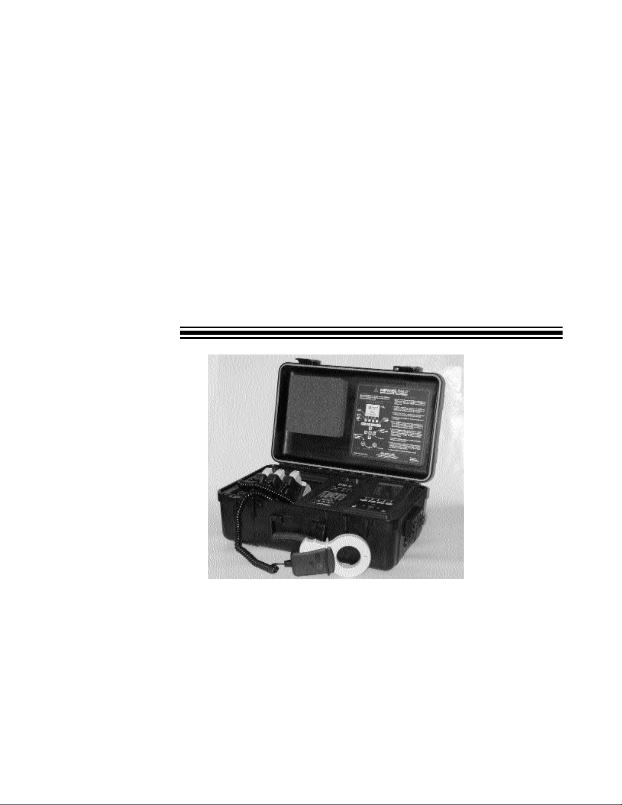
AMPROBE®
DMII™PRO
Data Logger Recorder
User ’s Manual
Amprobe thanks you for purchasing the DMII PRO. For your safety, please read
this instruction manual in its entirety.
z
Part No. 995758
Rev.A
Page 2

SAFETY PRECAUTIONS & WARNINGS
1.Read this manual in its entirety before proceeding.
2.This equipment should only be used by trained professionals who
are familiar with electrical hazards.
3.In many instances you will be working with dangerous levels of
voltage and/or current, therefore, it is important that you avoid direct
contact with any uninsulated current-carrying surfaces. Wear lineman
gloves, safety glasses and protective clothing at all times.
4.Before installing or removing batteries and/or fuses, disconnect all
inputs to the instrument and remove power cord from the outlet.
5.Before applying test leads to circuit under test, make certain that
leads are plugged into proper jacks.
6.Before using the DM-II PRO, always check condition of instrument
and accessories. Replace any damaged parts.
7.The unit should be checked on a known live line to verify it is
operating before using.
!
Page 2
Page 3

R Table of Contents
Introduction . . . . . . . . . . . . . . . . . . . . . . . . . . . . . . . . . . . . . . . . . . . . . . . . . . . . . . . . . . . . . . . . . . .4
Phase Set-up . . . . . . . . . . . . . . . . . . . . . . . . . . . . . . . . . . . . . . . . . . . . . . . . . . . . . . . . . . . . . .5, 6, 7
CT Set-up . . . . . . . . . . . . . . . . . . . . . . . . . . . . . . . . . . . . . . . . . . . . . . . . . . . . . . . . . . . . . . . . . . . .8
Clock Set-up . . . . . . . . . . . . . . . . . . . . . . . . . . . . . . . . . . . . . . . . . . . . . . . . . . . . . . . . . . . . . . . . . .9
Language Set-up . . . . . . . . . . . . . . . . . . . . . . . . . . . . . . . . . . . . . . . . . . . . . . . . . . . . . . . . . . . . . . .9
Communication Mode . . . . . . . . . . . . . . . . . . . . . . . . . . . . . . . . . . . . . . . . . . . . . . . . . . . . . . . . . . .10
Fund (Fundamental Frequency) Mode . . . . . . . . . . . . . . . . . . . . . . . . . . . . . . . . . . . . . . . . . . . . . .10
Meter Mode . . . . . . . . . . . . . . . . . . . . . . . . . . . . . . . . . . . . . . . . . . . . . . . . . . . . . . .11, 12, 13, 14, 15
Record Mode . . . . . . . . . . . . . . . . . . . . . . . . . . . . . . . . . . . . . . . . . . . . . . . . . . . . . . . .16, 17, 18, 19
Viewing Data . . . . . . . . . . . . . . . . . . . . . . . . . . . . . . . . . . . . . . . . . . . . . . . .20, 21, 22, 23, 24, 25, 26
Symbols & Definitions . . . . . . . . . . . . . . . . . . . . . . . . . . . . . . . . . . . . . . . . . . . . . . . . . . . . . . . . . .27
Fuse Replacement/Voltage Protection Procedure . . . . . . . . . . . . . . . . . . . . . . . . . . . . . . . . . . . . . .28
Total Power Quantities . . . . . . . . . . . . . . . . . . . . . . . . . . . . . . . . . . . . . . . . . . . . . . . . . . . . . . . . . .29
Battery Replacement . . . . . . . . . . . . . . . . . . . . . . . . . . . . . . . . . . . . . . . . . . . . . . . . . . . . . . . . . . .30
Setting Voltage Selection Switch . . . . . . . . . . . . . . . . . . . . . . . . . . . . . . . . . . . . . . . . . . . . . . . . . . .31
Specifications . . . . . . . . . . . . . . . . . . . . . . . . . . . . . . . . . . . . . . . . . . . . . . . . . . . . . . . . . . . . . .32, 33
User Interface . . . . . . . . . . . . . . . . . . . . . . . . . . . . . . . . . . . . . . . . . . . . . . . . . . . . . . . . . . . . . . . .34
Notes . . . . . . . . . . . . . . . . . . . . . . . . . . . . . . . . . . . . . . . . . . . . . . . . . . . . . . . . . . . . . . . . . . . . . . .35
Helpful Hints in using this manual:
All button commands will be represented in a bold typeface.
For example - Press HOLD button
You will be able to walk your way through the commands by following the Steps indicated in each
section.
For example - Step 1, Step 2, etc.
Page 3
Page 4

Congratulations! You have just purchased Amprobe’s DM-II (PRO) Data Logger Recorder. This
instrument was designed to assist you in your work. We have written this manual in a user
friendly, easy-to-follow format. Follow the steps and you will find it to be simple to use.
As you browse through the screens, you will find there are four sections. We will walk you
through them with ease. First, in order to begin, you must
Step 1 - TURN
THE DM-II ON
Push the ON/OFF button and hold it for a second. The green or red light will come on.
• Green indicates your instrument is powered by 110V.
• Red indicates your instrument is powered by batteries. Batteries are used as a
power back-up. If the power is interrupted, the DMII will continue recording using its
internal batteries.
The LCD screen will briefly display an information screen, then will finally switch to a SET-UP
screen.
Step 2 - ADJUST THE BRIGHTNESS OF YOUR LCD SCREEN
Since the LCD screen is sensitive to temperature, the brightness of your screen may
vary as the ambient temperature changes. If your screen is very dark
or completely
black, push the red ENTER button on your keypad and hold the key.
While holding ENTER button, push left ARROW button simultaneously and hold for a few
seconds.
If your screen is very light
, or BLANK push the red ENTER button and right ARROW button
simultaneously and hold for a few seconds.
R Introduction
Page 4
ENTER
Page 5
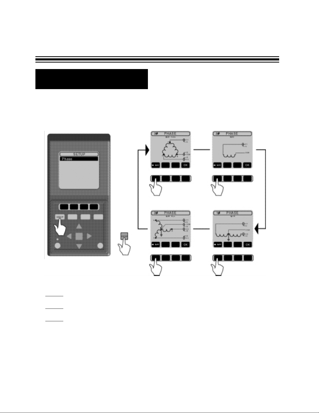
In order to prepare your DM-II PRO for operation, follow the various steps indicated in the diagrams that follow:
STEP 1 - Press SET-UP button (phase should be highlighted).
STEP 2 - Press ENTER
STEP 3 - Scroll through the 4 Phase screens. Before you press OK, check Drawings
A through D (on pages 6 - 7) for instructions for connecting test leads. Press OK after the test
leads are connected.
R Phase Set-up
Page 5
Page 6
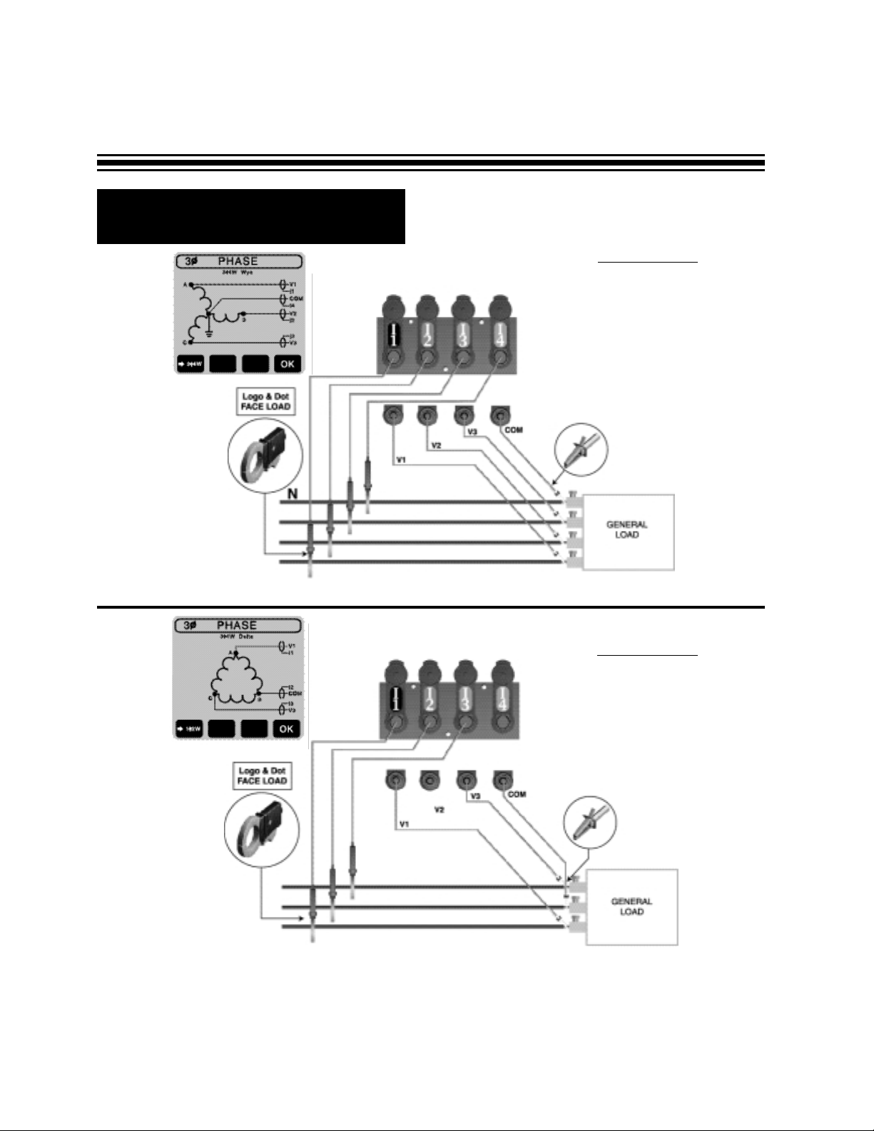
R Phase Set-up (cont’d.)
DRAWING A
3-Phase 4-Wire
(phase to neutral measurement)
DRA
WING B
3-Phase 3-Wire
(phase to phase measurement)
Page 6
NOTE: V2 and I4 inputs are NOT used.
NOTE: Use 3-Phase 3-Wire set-up (below) for phase voltage measurement on 3-phase 4-wire system.
Page 7
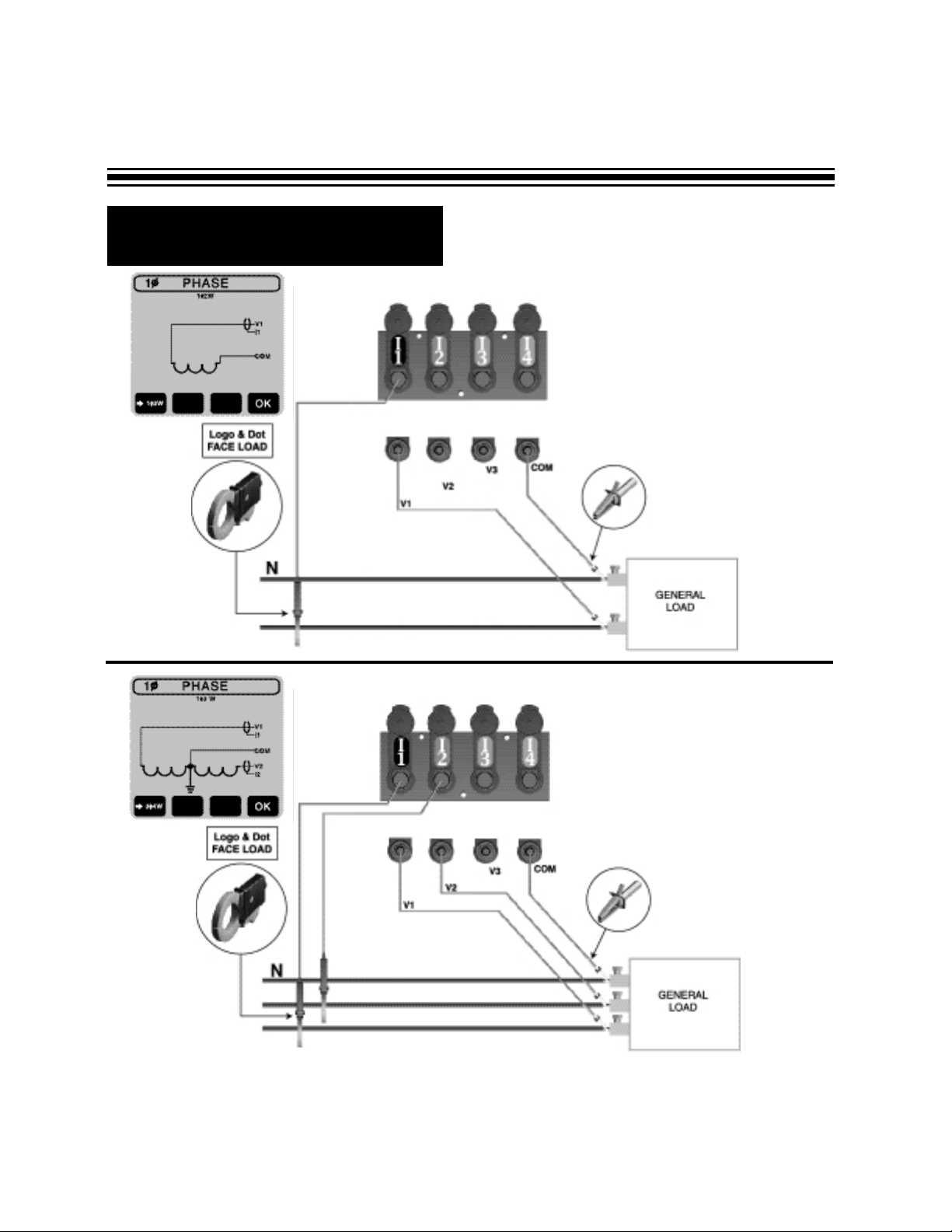
R Phase Set-up (cont’d.)
DRAWING C
1-Phase 2-Wire
DRAWING D
1-Phase 3-Wire
Page 7
Page 8
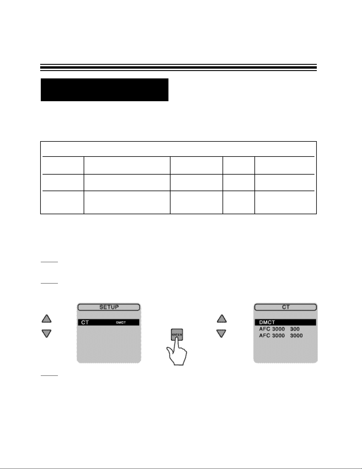
R CT Set-up
Check if the type of CT’s you are using matches the set-up on the DM-II PRO.
To set up the ACF-3000 itself, please refer to the ACF-3000 DM manual.
To change a CT set-up on the DM-II
Step 1
- Simply highlight CT in Setup screen using up/down arrows on the keypad and press
ENTER (red square).
Step 2
- Using same arrow keys, highlight desired CT.
Step 3
- Press ENTER again.
PROPER SET-UP
TYPE OF CURRENT TRANSDUCERS RANGE OF THE DM-II
DM-CT or Standard CTs 0-1000 amps CT DM-CT
DM-CT CE shipped with every DM-II PRO
ACF-3000DM Optional flexible CTs set-up 30-300 amps CT ACF3000 300
ACF-3000 DM Optional flexible CTs 300-3000 amps CT ACF3000 3000
Page 8
Page 9
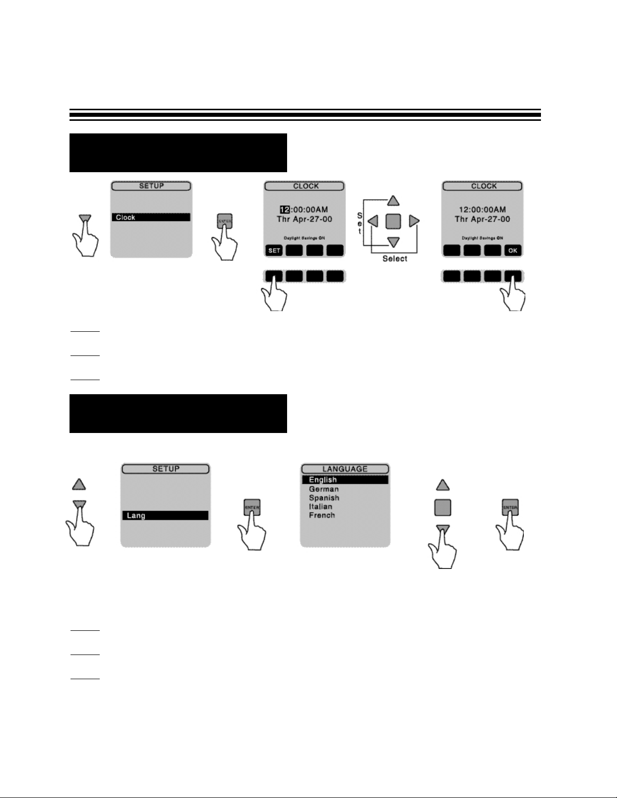
R Language Set-up
R Clock Set-up
To change a language:
Step 1
- In the SET-UP screen, using arrow keys select a lang and press ENTER
Step 2
- Select your desired language.
Step 3 - Press ENTER.
If you are satisfied with the choice of language on your screen, skip this section.
Page 9
Step 1
- Under SET-UP screen, using arrows on the keypad, select clock, then press ENTER.
Step 2
- If clock needs to be changed, using arrow keys, change time and date.
Step 3 - Once correct information has been obtained, press OK to return to SET-UP screen.
Page 10
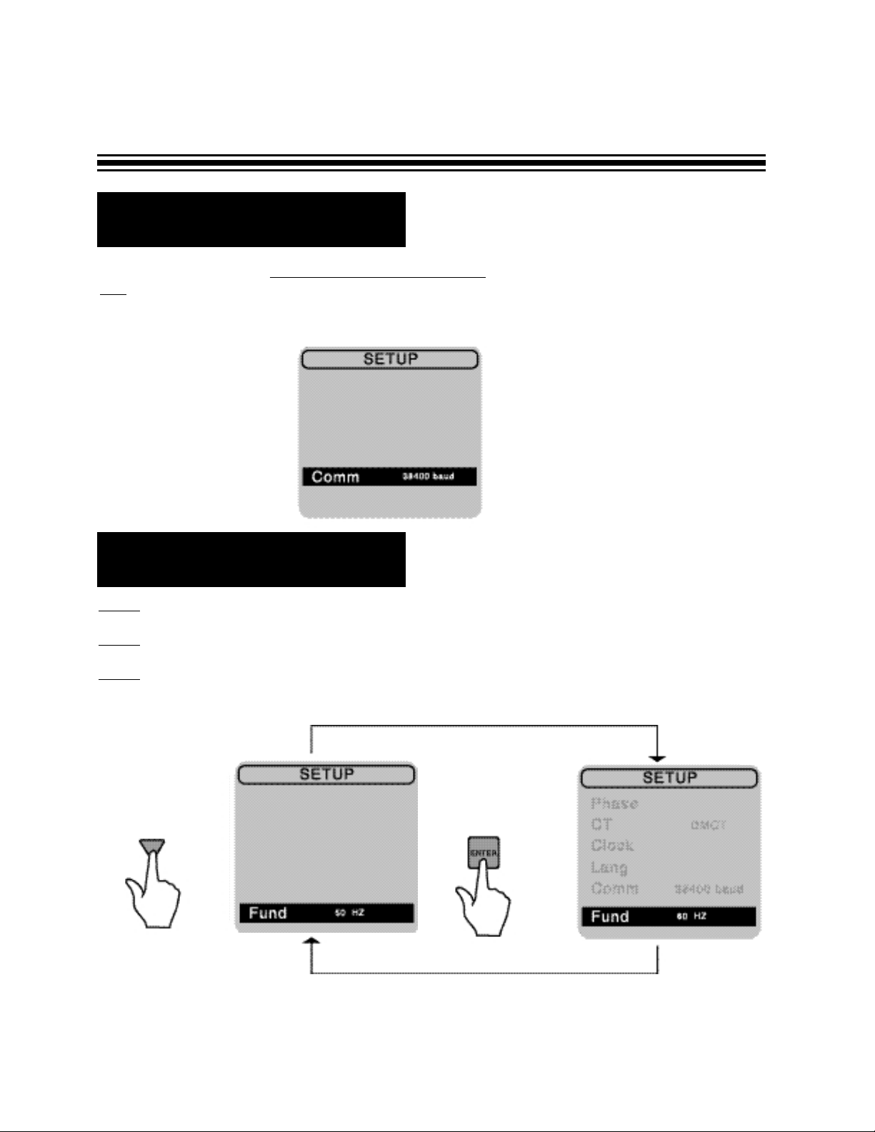
R Communication Set-up
You may skip this section. No set-up is required at this stage. The Communication Mode is used
only
when downloading data to a computer. Disregard the baud rate indicated on your screen, it will
be selected before you download to your PC. Please refer to the software section of your manual on
how to use this feature.
Page 10
R Fund (Fundamental
Frequency) Set-up
Step 1
- Select a FUND under SET-UP screen.
Step 2
- Using arrows on keypad, press ENTER to toggle between 50 or 60 Hz.
Step 3 - Once the user selects the fundamental frequency of the system, this frequency will
become the default setting.
Page 11

Page 11
R Meter Mode
VERIFYING A
PROPER SET-UP OF THE DM-II PRO
IMPORTANT NOTE:
Always perform this check. it will only take you a minute to verify a correct set-up, but you may
lose weeks or months of work if the DM-II PRO was set-up improperly.
Step 1
- Push the METER button. Check the following:
• P (Real Power) on each of the phases should be positive. If it is negative, reverse the
direction of the CT to make the color dot and Amprobe logo face the opposite way.
• Check if voltage and amperage (current) ranges on each of the phases are within expected
values. For example if nominal voltage of the system is 480V, but you are reading only
270V something is apparently wrong. In this case double -check the set-up of the test leads
and the DM-II itself.
The meter mode allows you to view real time readings of voltage, current, power, power factor.
Step 2
- Begin meter mode by pressing METER button. For definitions of terms see Pages 16 & 17.
Depending on phase set-up, there are different screens for you to view data.
METER MODE SCREENS FOR DIFFERENT PHASE SET-UPS
Meter mode for 3
ø4W - Page 12
Meter mode for 3
ø3W - Page 13
Meter mode for 1ø2W - Page 14
Meter mode for 1
ø3W - Page 15
For details on how to scroll through the screens, refer to the drawing on Page 12.
Page 12

R Meter Mode - 3Ø 4 Wire
Page 12
Press the corresponding button labeled: either ØA, ØB, or ØC to
view respectively phase A, B or C; press RN to view current in the
neutral wire, press TOTAL to view power and power factor.
NOTE: Indicated readings should be of an actual condition.
Go to Phase B
Go to Phase C
Go to Neutral Wire
Go to Total Power Readings
Page 13

R Meter Mode - 3Ø 3 Wire
Using the TOTAL (corresponding black key), you can display the total 3-Phase power measurements
from all three phases.
Use LINE V &
I button to go back to volt and amp.
NOTE: Indicated readings should be of an actual condition.
Page 13
Page 14

R Meter Mode - 1Ø 2 Wire
Page 14
NOTE: Indicated readings should be of an actual condition.
Page 15

R Meter Mode 1Ø 3 Wire
Press V2I2 to view Phase 2
Press V1I1 to view Phase 1
Page 15
NOTE: Indicated readings should be of an actual condition.
Page 16

R Record Mode
Step 1
- Press the RECORD button .
Step 2 - Select parameters for recording.
• SELECT ALL button will select all of the parameters for recording. All grid boxes will
become black. The DMII™ is going to record everything.
• CLEAR ALL button deselects all parameters. All grid boxes will become blank. When
this is selected, the DMII™ will NOT record anything.
• Selecting or deselecting one parameter at a time. Using the arrow keys, you can move
the blinking cursor to one of the selection boxes.
Press the ENTER button, to change between blank (not record) and black (record).
For RMS voltage and current, you can change between blank, black or black with “T”
(Threshold).
Page 16
ARROW KEYS
Black box indicates parameter selected
for recording.
Box with T indicates parameter selected
for recording with threshold parameters
indicated.
Blank box indicates parameter not
selected for recording
Page 17

R Record Mode (cont’d.)
Threshold Set-up and Features
The threshold feature is available for RMS voltage or current only (the first upper row). The
DMII™ is going to record only those values, that are between threshold parameters. Any values
beyond threshold will be recorded as zero. Threshold feature is not going to give any additional
time for recording.
To set-up threshold, follow these steps:
• Set up RMS voltage or current selection box to black with “T” and make sure it is blinking
(refer to previous section)
• Push SET button
• Press ZERO button to clear previous or current set-up of LO or HI bounds.
• Using arrow keys set LO (low) and HI (high) parameters of the threshold, RIGHT and
LEFT arrows allow you to move between digits. UP and DOWN allows you to enter the values.
• Press OK to enter changes.
• Threshold LO and HI parameters will appear on the screen.
Step 3
- Press SET SCHEDULE to access scheduling screen (see drawing on Page 18)
In the scheduling screen there are three different recording variables that the user must set:
MODE, RATE AND INTERVAL. Using the arrow keys, you can move between Mode, Rate
and Interval.
MODE
Normal - THE DMII will automatically stop when the memory is full.
Loop - THE DMII will override previously recorded data except events like:
A) max D) peak
B) min E) energy
C) average F) demand
These data values are going to be stored even if the DMII starts looping. This feature is very useful if
you are interested in recording events. One of the application examples could be recording energy on
demand throughout thirty days.
T
otal Available Time of Recording
At the bottom section of the screen, you will find information about total available time of recording.
The DMII is going to stop recording after this time. Note: It shows you a number of years, months
and days before hours, minutes and seconds.
You can change the total time of recording in two ways:
• Changing rate - The lower the rate, the shorter total time of recording. If you record on
demand, you will not
be able to change the rate.
Page 17
Page 18

R Record Mode (cont’d.)
Page 18
User selectable recording rates:
1 second, 5 seconds, 15 seconds, 30 seconds,
1 minute, 5 minutes, 15 minutes, 30 minutes.
INTER
VAL - You should set up INTERVAL either to
15 or 30 minutes if you want to measure Energy on
Demand. In this case your rate will be locked to
one second according to definition. For any other
measurements, set-up INTERVAL to NONE, this
allows you to choose one of the available rates on
the DMII.
What is Energy on Demand?
If power plant is not able to supply
enough energy for customer using their
regular resources, they need to produce
energy on demand. The cost for using
this energy will be higher than regular.
To compute this amount, the power
plant measures average power in 15
or 30 minute intervals with a rate of
1 second throughout 30 days time. For
their energy cost computations, they
take the highest average result.
• Changing number of parameters selected for recording - The more parameters selected,
the shorter the total time of recording.
If you are recording events like max, min, average, peak or energy only
, there is no time limit for
recording. The total length of recording for all parameters will be shown as zeros on the screen.
RA
TE - The recording rate is how often the DMII is going to record data. For example, within a 15 sec-
ond rate, the device is going to record once every 15 seconds. The rate affects the total available time
of recording. Please refer to the section “Total Available Time of Recording” for details.
You can select rate only if INTERVAL is set-up to NONE.
Otherwise the rate will be locked to one second
(refer to Energy on Demand section)
Page 19

R Record Mode (cont’d.)
Step 4 - Start, Stop Recording - Press the START button. This will take you to the confirmation
screen.
• If you press the START button again you will start a recording session.
W
ARNING: All previously stored data in the memory will be erased. If you want to
cancel and return to the RECORD selection screen, press NO (middle right black button).
Previously recorded data will remain in the memory.
• To start a recording session, press START. Remember, all previously recorded data
will be lost.
• To terminate the recording session, press STOP button.
NOTE:
YOU WILL TERMINATE THE RECORDING SESSION BY
PRESSING
ON/OFF BUTTON.
At this stage you can view data being recorded by pressing view button. Please refer to the
next section on Page 21.
Page 19
Page 20

R Viewing Data
It is not necessary for you to download to a PC in order to view your recorded data. You have the
option of viewing the data directly on the DMII LCD screen. Note that while the data is being recorded,
the scroll feature of the charts is not available. All features will be available when the recording session
is complete.
Step 1
- To view data, simply push the VIEW button.
• A black selection box indicates that the parameter was recorded and can be viewed.
• A blank selection box indicates that the parameter was NOT recorded and cannot be
viewed.
Depending on the phase set-up you will see one of the four screens:
Page 20
Page 21

Page 21
NON DEMAND RECORDING (interval was set up to NONE)
Note: If you recorded on-demand (interval was set up to 15 or 30 min.) skip this section and go to the
next one.
To view desired parameter, move blinking cursor to the parameter.
If you selected parameter other than POWER, press ENTER.
Press VIEW button to return to the *You will be able to scroll throughout
selection screen. the chart only if recording was finished.
R Viewing Data (cont’d.)
For events, max, min, ave, peak
or energy the numerical value
wil be displayed.
For example:
For RMS value, a chart will
be displayed.
For example:
ENTER
ENTER
Page 22

If you selected power, push corresponding black button to view:
P - Real Power
Q - Reactive Power
S - Apparent Power
PF - Power Factor
Press VIEW button to return to the selection screen.
Here is an example for single phase system:
Notice that if you are viewing data while recording, you can’t scroll through the data. This feature
will be available after the recording is finished.
R Viewing Data
Page 22
Page 23

Page 23
R Viewing Data (cont’d.)
ON DEMAND RECORDING (INTERVAL was set-up to either 15 or 20 minutes during recording).
To view desired parameter, move blinking cursor to the parameter.
- If you selected RMS, the chart on Page 21 will be shown.
- If you selected POWER, the parameters are going to be displayed the same way as on Page 22.
- If you selected events, max, min, ave, peak or energy - the total and interval selection is available
(explained in the next section).
Page 24

Page 24
R Viewing Data (cont’d.)
If you selected DEMAND (available for three phase set-up only), the peak and interval selection is
available (explained in the next section).
Page 25

Page 25
R Viewing Data (cont’d.)
Total will show the event value for entire recording session (this value is NOT GOING to be overwritten
if the DM-II is looping
Interval - Points on the graph represent event values for each of the time intervals (these values ARE
going to be overwritten if the DM-II starts looping).
TOTAL (EVENT)
INTERVAL
Page 26

R Viewing Data (cont’d.)
Page 26
DEMAND - will show the Peak Demand for entire recording session (this value is not
going to be overwritten if the DM-II starts looping). For Peak Demand definition, refer to
Page 18 “What is Energy on Demand?”
Page 27

R Symbols & Definitions of
Terms Used on the DM-II
SYMBOLS AND DEFINITIONS OF TERMS USED ON THE DM-II
V (V) - Voltage RMS
I (A) - Current RMS
S (V A) - Apparent Power
P (W or kW) - Working Power
Q (VAR) - Reactive Power
PF - Power Factor
RMS
Root mean square value, which is the effective value of an alternating current or voltage. Unless
otherwise specified, the AC values are always RMS i.e. the typical receptacle is 110V RMS.
RMS max
Greatest, maximum value of the RMS voltage or current which occurred during the recording time.
RMS min
Lowest, minimum value of the RMS voltage or current which occurred during the recording time.
RMS avg
Average RMS value of voltage or current, which is a sum of all RMS measured values divided by
the number of values
PEAK max
The greatest instantaneous value of voltage or current (the highest point of the sinusoid)
1
ø Power
Power in the selected phase
1
ø Energy
Energy in the selected phase
3
ø Power
Total power in all phases
3
ø Energy
Total energy in all phases
3
ø Demand
The highest average usage of energy during 15 or 30 minute intervals throughout 30 day period of
time.
V
AN, VAB
Letters used in a subscript describe what are the reference points for measurement i.e. VAN - Voltage
between phase Aand Neutral wire, VAB - Voltage between phase Aand B.
Page 27
Page 28

Page 28
DM-II™ Fuse Replacement/Voltage Selection Procedure
True RMS Voltage and Current (volts and amps): True RMS is calculated by using Parseval’s
theorem:
Real Power P (watts): The real power that performs the work of creating heat, light, motion, machine
output, etc.
Apparent Volt-Amperes S (VA): The total power required to be generated to provide the desired working power output.
Reactive Volt-Amperes Q (VAR): The “non-working” or “phantom” power that is needed to charge
capacitors and magnetize inductors, i.e. reactive power to sustain electromagnetic fields.
Vrms = √Σ
V
2
n
n
P = Σ
V
rms
n
I
rms
n
COS (
θ
DIFF
n
)
n
Q = Σ
V
rms
n
I
rms
n
sin (
θ
DIFF
n
)
n
S =
V
rmsIrms
Irms = √Σ
I
2
n
n
Page 29

Page 29
True Power Factor PF: The ratio of working power or Real Power, P, to Apparent Power, S. It measures how effectively electrical power is being used by the system. The Displacement Power Factor has
traditionally been calculated by examining the phase angle between the fundamental voltage and current
and is equal to cos (θ). This traditional method only works for linear, sinusoidal systems. The DM-II™,
however, calculates the True Power Factor, which also works for non-linear, non-sinusoidal systems.
Power factor can be leading or lagging, depending on the sign of the reactive Volt-Amperes Q (VAR).
The following table summarizes:
Power Factor
Sign of Q Type of Load Current/Voltage Relationship
Lagging Positive Inductive Current Lags Voltage
Leading Negative Capacitive Current Leads Voltage
DM-II
™ Total Power Quantities (P
, Q, S, PF) for 3Ø Systems
3Ø 3W Delta and 3Ø 4W Wye configurations include total calculations for P, Q, S, and PF, based upon
the following formulas.
Total Power, P
Total:
P
Total =
P
ØA
+
P
ØB
+
P
ØC
Total Reactive Volt-Amperes, QTotal:
QTotal =
Q
ØA
+
Q
ØB
+
Q
ØC
Total Apparent Volt-Amperes, STotal:
Total Power Factor, PFTotal:
PF =
P
S
PF
Total
=
PTotal
STotal
STotal = √P
2
+
Q
2
Total Total
Page 30

Page 30
Step 1 - Remove the battery cover by turning the two cover screws 3/4 turn counter clockwise.
Step 2 - Remove batteries from battery compartment.
Step 3
- Install new batteries. Use six “D” size alkaline batteries. Always replace all six
batteries at the same time. observe polarity symbols on battery holder.
Step 4
- Replace battery cover and tighten two lid cover screws.
COVER SCREWS
R Battery Replacement
Page 31

Page 31
To set voltage selection switch:
1. Disconnect the power cord from the power entry module.
2. Use a small screwdriver to open the fuse compartment door. Remove the drawer by pulling it out of
the power entry module.
3. Rotate the fuse holder so that the desired voltage setting is aligned with the window. Slide the fuse
holder back into the compartment until it snaps into place.
4. Snap the fuse compartment door back into place.
Fusing:
The fuse holder accepts the 0.25A@250V 1/4” 1/4” x 1-1/4” 5 x 20mm fuse.
WARNING: For continued protection against fire hazard, replace only with the same type and
rating of fuse as specified.
Page 32

M
ODEL DM-II™
Data Logger/Recorder
Specifications
Inputs:
Voltage: Three voltage channels with common (V1, V2, V3, and COM). The test leads are flexi-
ble straight sheathed banana plugs on each end, rated for 1000Vrms and a length of 6 Ft.
(set of four supplied). The alligator clips have a 1 in. jaw opening and are rated at 10A max.
(set of four supplied).
Current: Four channels (I1, I2, I3, I4)
DM-CT: 1 to 1000A ±1% of reading (four supplied)
ACF-3000:
30A to 300A ±1% of full scale
300A to 3000A ±1% of full scale
Note: The ACF-3000 is an optional accessory. Atotal of three would be
required for a 3Ø measurement.
Ranges:
AC Voltage measurements (True RMS) 5 to 600 Vrms
AC Current measurements (True RMS) 1 to 1000 Arms with four supplied DM-CTs
Accuracy:
Voltage measurements ±1% of reading + 3 LSDs
Current measurements ±1% of reading + 3 LSDs
Voltage and Current measurement selections:
True RMS voltage and current, RMS max, RMS min, RMS avg, Peak max
Power measurement capabilities:
Real power P (watts), Apparent Volt-amperes S (VA),
Reactive Volt-amperes Q (VAR), True Power Factor (tPF),
Energy measurement capabilities:
Kilowatt Hours (KWH), Demand (KW)
Programmable Thresholds:
User selectable high/low limits for RMS voltage and current
Recording Modes/Rates/Intervals:
User selectable normal and loop (wrap around) recording modes, user selectable
recording rates of 1 second, 5 seconds, 15 seconds, 30 seconds, 1 minute, 5 minutes,
15 minutes, and 30 minutes. User selectable recording intervals of none, 15 minutes,
and 30 minutes.
Page 32
Page 33

M
ODEL DM-II™ PRO Data Logger/Recorder (cont’d)
Memory:
Total of 600K RAM memory. The recording session length depends on the recording
rate, the number of parameters selected for recording, recording mode, and recording
interval. The memory has a lithium backup battery to preserve its contents in event of
the absence of AC power and batteries.
Real Time Clock:
User programmable real time clock, displayed in 12/24 hour format and HH:MM:SS Day
Month Date Year, daylight savings option, accuracy of ±1 minute per month.
System Configuration:
Total of four prestored setup phase configurations for 1Ø and 1Ø systems: 1Ø 2W, 1Ø
3W, 3Ø 3W Straight Delta, and 3Ø 4W Wye.
Note: Any or all parameters of a phase configuration can be recorded.
PC Interface:
Optically isolated RS-232 serial interface. DM-II View™ PRO software for display, data
analysis, and report generation. User selectable baud rates of 9600, 19200, and 38400
baud.
Power Requirements:
AC line voltage with battery backup operation. The ON/OFF dual color LED indicates the
unit’s power source: green indicates AC line power, red indicates battery power.
Safety Standards:
Designed to meet: UL3111-1, CE (LVD/EMC/EMI)
Case:
Material: Injection molded flame retardant ABS911, rugged, water-resistant, and
corrosion proof.
Case dimensions: 17.5” x 11.6” x 7.5”
Weight: 16 lbs. (7.3 kgs.) includes batteries, 4 CTs, voltage leads and alligator clips.
Important - Be sure that the pressure relieve valve located next to the handle is open
when encountering atmospheric changes.
Battery:
Six alkaline “D” cells (not supplied)
Battery Life:
21 hours continuous with backlight OFF, 1 second recording rate, normal recording
mode, all parameters elected for a 3Ø 4W Wye configuration.
Operating Temperature Range:
32º - 122ºF (0ºF - 50ºC), Relative humidity <85%
Storage Temperature Range:
28º - 140ºF (-2ºF - 60ºC), Relative humidity <90%
Page 33
Page 34

User Interface
Graphic Display:
User adjustable contrast, LED backlight, 160 x 160 pixel, STN
Switch Keypad:
15 key membrane switch keypad, shielding protection, embedded dual color red/green
LED indicating power from line voltage or from batteries.
System Requirements for DM-II View™ PRO
Windows™ 95/98/NT/2000
Pentium Processor or higher
8 MB RAM minimum, 16 MB recommmended
ACCESSORIES & REPLACEMENTS
Test Leads & Alligator Clips (set of four) DVL-4
Current Transducer (Black) DM-CT-BL-CE
Current Transducer (Red) DM-CT-R-CE
Current Transducer (Blue) DM-CT-B-CE
Current Transducer (Yellow) DM-CT-Y-CE
Output Lead RS-232
Power Cord PC-4
DM-II View™ PRO 3.5” Discs (set of 2) DISC-II
Flexible Current Transducer (3000 Amps) ACF-3000 DM
DM-II™ PRO Instruction Manual
DM-II View™ PRO Instruction Manual
Page 35

NOTES
Page 36

Telephone: 305-757-8811 Fax: 305-757-2153
www.amprobe.com
 Loading...