

Page 1

Users Manual
Mode d’emploi•
Bedienungshandbuch•
Manuale d’Uso•
Manual de uso•
Användarhandbok•
DM-II PLUS
Power Quality Recorder
Page 2

Page 3

DM-II PLUS
Power Quality Recorder
Users Manual
DMIIPLUS_Rev004
© 2008 Amprobe Test Tools.
All rights reserved.
English
Page 4

Limited Warranty and Limitation of Liability
Your Amprobe product will be free from defects in material and workmanship for 1 year from
the date of purchase. This warranty does not cover fuses, disposable batteries or damage from
accident, neglect, misuse, alteration, contamination, or abnormal conditions of operation or
handling. Amprobe’s warranty obligation is limited, at Amprobe’s option, to refund of the
purchase price, free of charge repair, or replacement of a defective product . Resellers are not
authorized to extend any other warranty on Amprobe’s behalf. To obtain service during the
warranty period, return the product with proof of purchase to an authorized Amprobe Test
Tools Service Center or to an Amprobe dealer or distributor. See Repair Section for details. This
warranty is your only remedy . All other warranties - whether express, implied or statutory including implied warranties of fitness for a particular purpose or merchantability, are hereby
excluded. Neither Amprobe nor its parent company or affiliates shall be liable for any special,
indirect, incidental or consequential damages or losses, arising from any cause or theory. Since
some states or countries do not allow the exclusion or limitation of an implied warranty or of
incidental or consequential damages, this limitation of liability may not apply to you.
Repair
All test tools returned for warranty or non-warranty repair or for calibration should be
accompanied by the following: your name, company’s name, address, telephone number, and
proof of purchase. Additionally, please include a brief description of the problem or the service
requested and include the test leads with the meter. Non-warranty repair or replacement
charges should be remitted in the form of a check, a money order, credit card with expiration
date, or a purchase order made payable to Amprobe® Test Tools.
In-Warranty Repairs and Replacement – All Countries
Please read the warranty statement and check your battery before requesting repair. During
the warranty period any defective test tool can be returned to your Amprobe® Test Tools
distributor for an exchange for the same or like product. Please check the “Where to Buy”
section on www.amprobe.com for a list of distributors near you. Additionally, in the United
States and Canada In-Warranty repair and replacement units can also be sent to a Amprobe®
Test Tools Service Center (see below for address).
Non-Warranty Repairs and Replacement – US and Canada
Non-warranty repairs in the United States and Canada should be sent to a Amprobe® Test
Tools Service Center. Call Amprobe® Test Tools or inquire at your point of purchase for current
repair and replacement rates.
In USA In Canada
Amprobe Test Tools Amprobe Test Tools
Everett, WA 98203 Mississauga, ON L4Z 1X9
Tel: 877-993-5853 Tel: 905-890-7600
Fax: 425-446-6390 Fax: 905-890-6866
Non-Warranty Repairs and Replacement – Europe
European non-warranty units can be replaced by your Amprobe® Test Tools distributor for a
nominal charge. Please check the “Where to Buy” section on www.amprobe.com for a list of
distributors near you.
European Correspondence Address*
Amprobe® Test Tools Europe
Beha-Amprobe GmbH
In den Engematten 14
79286 Glottertal, Germany
Tel.: +49 (0) 7684 8009 – 0
*(Correspondence only – no repair or replacement available from this address. European
customers please contact your distributor.)
2
Page 5

DM-II PLUS
Power Quality Recorder
CONTENTS
Precautions and Safety .........................................................................................................................5
Symbols ..............................................................................................................................................5
Safety Information ............................................................................................................................5
Warnings and Precautions ................................................................................................................5
Instrument: Description .................................................................................................................... 7
Keyboard: Description ......................................................................................................................7
Display: Description...........................................................................................................................7
Menu General – Settings (Refer to Fig.1) ........................................................................................7
Default Settings.................................................................................................................................8
System Connections ..............................................................................................................................8
Operation ..............................................................................................................................................8
Single Phase System (Refer to Fig.2) ................................................................................................ 8
Three Phase Four Wire System (Refer to Fig.3) ............................................................................... 9
Three Phase Three Wire System (Refer to Fig.4) ............................................................................. 9
Measuring Procedures ........................................................................................................................10
Recommended Procedure for a recording ....................................................................................10
To Start a Recording ........................................................................................................................10
During a Recording: (Refer to Fig.5) ..............................................................................................10
Stop a Recording .............................................................................................................................10
Connection with a PC......................................................................................................................11
Evaluating Parameter Values..............................................................................................................11
Voltage (Refer to Fig.6) ..................................................................................................................11
HARM. Mode (Refer to Fig.7) .........................................................................................................11
WAVE Mode (Refer to Fig.8) .......................................................................................................... 12
Current (Refer to Fig.9) ...................................................................................................................12
Power (Refer to Fig.12) ...................................................................................................................13
Energy (Refer to Fig.15) ..................................................................................................................14
Analyzer Config, Recorder Config, and Analyzer Memory .............................................................. 14
Analyzer Configuration (Refer to Fig.16) ...................................................................................... 14
Recorder Configuration ..................................................................................................................15
Analyzer Memory (Refer to Fig.25) ................................................................................................18
Technical Specifications ...................................................................................................................... 19
Features ...........................................................................................................................................19
Environment ....................................................................................................................................23
3
Page 6

DM-II PLUS
Power Quality Recorder
Contents (continued)
Appendix .............................................................................................................................................23
Messages Displayed.........................................................................................................................23
Recordable Parameters Symbols ....................................................................................................25
4
Page 7

PRECAUTIONS AND SAFETY
Symbols
Caution, risk of electric shock.
See notes
Caution, risk of electrical shock
Earth (ground) TERMINAL
Audible tone
Complies with EU directives
Battery
Equipment protected throughout by DOUBLE
INSULATION or REINFORCED INSULATION
Alternating Current
Conforms to relevant Australian
standards.
Do not dispose of this product as unsorted
municipal waste.
Application around and removal from hazardous
live conductors is permitted
Safety Information
The DM II Plus conform to EN61010-1:2001; EN61010- 2-032:2002; CAT III 600 V, Insulation •
Class II and pollution deg. 2. and EN 61557-7.
This instrument is EN61010-1 certified for Installation Category III (600V). It is •
recommended for use in distribution level and fixed installations, as well as lesser
installations, and not for primary supply lines, overhead lines and cable systems.
Do not exceed the maximum overload limits per function (see specifications) nor the •
limits marked on the instrument itself. Never apply more than 600 V ac rms between
phase to phase or 370 Vac phase to earth ground.
Warnings and Precautions
Before and after hazardous voltage measurements, test the voltage function on a •
known source such as line voltage to determine proper meter functioning.
Inspect the meter, clamps, test leads and accessories before every use. Do not use any •
damaged part.
Never ground yourself when taking measurements. Do not touch exposed circuit •
elements or test probe tips.
Do not operate the instrument in an explosive atmosphere.•
To reduce the risk of fire or electric shock, do not expose this product to rain or moisture.•
The meter is intended only for indoor use. To avoid electrical shock hazard, observe the •
proper safety precautions when working with voltages above 60 VDC, 42.4 Vpk, or 30
VAC rms. These voltage levels pose a potential shock hazard to the user.
Keep your hands/fingers behind the hand/finger barriers (of the meter and the test •
leads) that indicate the limits of safe access of the hand-held part during measurement.
Inspect test leads, connectors, and probes for damaged insulation or exposed metal •
before using the instrument. If any defects are found, replace them immediately.
This Clamp-on current sensor is designed to apply around or remove from un-insulated •
hazardous live conductors. Individual protective equipment must be used if hazardous
live parts of the installation could be accessible.
Exercise extreme caution when: measuring voltage >20 V // current >10 mA // AC power •
line with inductive loads // AC power line during electrical storms // current, when the
fuse blows in a circuit with open circuit voltage >1000 V // servicing CRT equipment.
Remove all test leads before opening the case to change the battery.•
To avoid false readings, which could lead to possible electric shock or personal injury, •
replace the batteries when the low battery indicator
To avoid electric shock hazard, do not use the HOLD mode to determine if a circuit is live. •
Unstable readings will not be captured and displayed.
For accurate measurements after long-term storage in severe environmental conditions, •
wait until the instrument returns to its normal operating conditions.
appears.
5
Page 8

UNPACKING AND INSPECTION
CAT III 600V MAX
v
V1 V2 V3
C
O
M
1
2
4
3
I1
I2
I3
12V dc
250 mA
+ -
1 2 3 4
Make sure that the instrument has suffered no damage during transit. If you find problems,
contact the carrier. Make sure all the accessories and parts listed below are included. If there is
a problem, contact your dealer.
Description Model Name
Instrument DM-II Plus
External power supply 12VDC DMT-EXTPS
3 clamp meters 1000 A/1V DM-CT-HTA-1000A
(code 1 pcs)
4 cables and alligators for voltage measurement KITENERGY3
1 Software CD DS2.3
Serial Cable C232NG1
➊
➊ RS232 Serial Output
➋
➌
➍
Display
➋
External power supply Plug
➌
Voltage and Current Inputs
➍
(see below)
Keyboard
➎
➎
Voltage Inputs
Phase 1 Input
➊
Phase 2 Input
➋
Phase 3 Input
➌
Phase Neutral Input
➍
Current Inputs
Phase 1 Current Input
➊
Phase 2 Current Input
➋
Phase 3 Current Input
➌
DC Power Supply Input
6
➍
Page 9

Instrument: Description
Keyboard: Description
ON/OFF: Turning on – turning off / Backlight ON (automatic Off after 5 sec.)
F1, F2, F3, F4: Navigation keys. Specific function appears at the bottom of the screen.
Voltage, Current,
Power, Energy: Go to the corresponding measurement.
MENU: Check and modify parameters
CANCEL: Return to a previous screen. Leave a menu or a sub-menu
ENTER/HOLD: double function key:
ENTER: Confirm the settings.
HOLD: Restrict values from updating. It is disabled when recording or
measuring energy. When enable, recording or measurement cannot
be taken.
SAVE: To save in the instrument memory a Record of “Smp”. It is disabled during a
recording.
START/STOP: Start/stop a recording
Display: Description
Initial Display
When you turn on the DM-II Plus, the display shows this initial screen.
The display is a graphic module with a resolution of128 x 128 pixels (16384 pixels overall).
SN – Serial number of the instrument
VER – Firmware software release
BAUD RATE – Transmission speed through serial I/O
Menu General – Settings (Refer to Fig.1)
Push MENU to access the MENU GENERAL screen.
Push ENTER to save changes, or CANCEL to go back to the previous MENU.
Push F1 or F2 to highlight sub-menus, F3 or F4 to change the settings, and + or – to change the
values.
NOTE: The Menu is not available during a recording or Real Time Energy measurement.
ANALYZER MEMORY – View instrument memory. See Section 6.3.
RESET – Change all settings back to default. Will not erase memory.
ANALYZER CONFIG – Set the type of electrical system under test, fundamental frequency,
current range, clamp type, transformer voltage ratio, and a password. See Section 6.1.
RECORDER CONFIG – Check and modify up to 64 recording parameters, turn on automatic
recording, set the Integration Period value, voltage sag and surge detection feature, and
harmonics detection feature. See Section 6.2.
7
Page 10

CONTRAST – Change the contrast of the display.
DATE&TIME – Set the date and time. Change the date format.
LANGUAGE – Change the language shown in the display.
Default Settings
The instrument is pre-set with a general configuration that should fit most cases. To adjust
these settings, see Section 6.
ANALYZER CONFIG:
Frequency: 60Hz
Full scale of the clamps: 1000A
Transforming ratio of volt metric transformers: 1
Type of electrical equipment: Four wires
Password: enabled
RECORDER CONFIG:
Start: Manual (once the START/STOP key is Pushed, the recording starts after 1 minute at
00 second mark.)
Stop: Manual
Integration period: 15min
Recording of harmonics: ON
Recording of Sag and Surge: ON
Voltage Reference for Sag and Surge detection: 230V
Upper Limit for Sag and Surge detection: 6%
Lower Limit for Sag and Surge detection: 10%
Selected voltages: V1, V2, V3
Selected voltage harmonics: Thd, 01, 03, 05, 07
Selected currents: I1, I2, I3, IN
Selected current harmonics: Thd, 01, 03, 05, 07
CO-GENERATION: OFF
Powers, Pf and cosϕ selected Pt, P1, P2, and P3
Qti, Q1i, Q2i, Q3i
Qtc, Q1c, Q2c, Q3c
St, S1, S2, S3
Pft, Pf1, Pf2, Pf3
dpft, dpf1, dpf2, dpf3
Energies: Eat, Ea1, Ea2, Ea3
Erit, Eri1, Eri2, Eri3
Erct, Erc1, Erc2, Erc3
Est, Es1, Es2, Es3
SYSTEM CONNECTIONS
Caution: If possible, before connecting the instrument to the electrical equipment to be
tested, take the power supply off the electrical equipment.
Do not measure voltages exceeding these limits or you could endanger your safety, damage
the instrument and/or its components.
OPERATION
Single Phase System (Refer to Fig.2)
Caution: The maximum voltage between L1 and COM inputs is 370V~ phase-earth.
8
Page 11

Connect the cables and the clamp as shown in fig. 2.1.
In the ANALYZER CONFIG menu, set the SYSTEM to SINGLE PHASE.2.
Set Frequency, Current Range, Clamp type, and TV Ratio.3.
Push ENTER to accept the changes4.
Push CANCEL to return to the last analysis screen display.5.
Push POWER to verify:6.
Direction of the clamp: Active power P must be positive. If it is negative, turn the clamp a.
around.
Phase Sequence:100b.
The value of the Pf of each phase is not lower than 0.4. If Pf is lower than 0.4, check if the c.
phase voltage is associated to the right clamp meter, (V1 is associated to clamp meter #1).
Push VOLTAGE, CURRENT, POWER, or ENERGY key for the analysis type. 7.
To interrupt the real time updating of the displayed values, push the HOLD key.
8. To record the values, see section 6.2.
Three Phase Four Wire System (Refer to Fig.3)
Caution: The maximum voltage between V1, V2, V3 & COM inputs is CAT III 600 V~ phase-
phase 370 V~ phase-earth.
Connect the cables and the clamps as shown in fig.3. 1.
In the ANALYZER CONFIG menu, set the SYSTEM to 3PH4W.2.
Set Frequency, Current Range, Clamp type, and TV Ratio.3.
Push ENTER to accept the changes4.
Push CANCEL to return to the last analysis screen display.5.
Push POWER to verify:6.
Direction of the clamp. Active power P must be positive. If it is negative, turn the clamp a.
around.
Phase Sequence:123b.
The value of the Pf of each phase is not lower than 0.4. If Pf is lower than 0.4, check if the c.
phase voltage is associated to the right clamp meter, (V1 is associated to clamp meter #1,
V2 to clamp meter #2, and V3 to clamp meter #3).
Push VOLTAGE, CURRENT, POWER, or ENERGY key for the analysis type.7.
8. To interrupt the real time updating of the displayed values, push the HOLD key.
9. To record the values, see section 6.
Three Phase Three Wire System (Refer to Fig.4)
Caution: The maximum voltage between V1, V2, V3 and COM (V2) inputs is CAT III 600 V~
phase-phase.
NOTE: The green cable (neutral) is connected with the red cable on phase 2.
Connect the cables and the clamps as shown in fig.4. 1.
In the ANALYZER CONFIG menu, set the SYSTEM to 3PH3W.2.
Set Frequency, Current Range, Clamp type, and TV Ratio.3.
Push ENTER to accept the changes4.
Push POWER to verify:5.
Direction of the clamp. Active power P must be positive. If it is negative, turn the clamp a.
around.
The value of the Pf of each phase is not lower than 0.4. If Pf is lower than 0.4, check if the b.
phase voltage is associated to the right clamp meter, (V12 is associated to clamp meter
#1, V32 to clamp meter #2, and V31 to clamp meter #3).
9
Page 12

Push CANCEL to return to the last analysis screen display.6.
7. Push VOLTAGE, CURRENT, POWER, or ENERGY key for the analysis type.
8. To interrupt the real time updating of the displayed values, push the HOLD key.
9. To record the values, see section 6.2.
MEASURING PROCEDURES
Caution: For recordings, ALWAYS use the external power supply.
If during a recording the external power supply is de-energized, the internal battery will be
used.
It is recommended that you ALWAYS insert a new set of batteries before a long recording.
Recommended Procedure for a recording
Check and modify the settings. See section 6.1. 1.
Push VOLTAGE, CURRENT, POWER, or ENERGY key for the analysis type.2.
Connect the instrument to the electrical system to be tested.3.
Evaluate the parameter values. See section 5.4.
If you want to record:5.
Decide what to record anda.
Push MENU to adjust settings (see section 2.3 for default settings). See section 6.b.
Connect the External Power Supply.6.
7. Start the recording by Pushing START/STOP.
To Start a Recording
Manually – Push the START/STOP key. When the timer gets to 00 seconds, the recording will
start.
Automatically –
Push MENU.1.
Select RECORDER CONFIG using Up 2. and Down keys. Push ENTER.
Push + or – key to change from MAN to AUTO. 3.
Push 4. to select month, day, year, hour, minute, and second.
Push + or – to set the Start date and time for the recording.5.
Push 6. to select STOP and push + or – key to change from MAN to AUTO.
Push 7. to select to month, day, year, hour, minute, and second.
Push + or – to set the Stop date and time for the recording.8.
Push 9. to select INT PERIOD. Push + or – to change it.
Push 10. to select HARM REC. Push + or – to turn it ON or OFF.
Push 11. to select ANOM REC. Push + or – to turn it ON or OFF.
Push CANCEL twice to return to the previous screen.12.
Push START/STOP key. The instrument will remain in stand-by until the set date and time.13.
Note: Make sure to push the START/STOP key or the recording will never start.
During a Recording: (Refer to Fig.5)
Push MENU to see the INFO screen. Push CANCEL to return to the previous screen.
Stop a Recording
If “PASSWORD” is enabled (Section 6), push F1, F4, F3, F2 within 10 seconds to enable the
MENU. Then, push START/STOP to stop the recording) or F2 (for energy measurements).
10
Page 13

Connection with a PC.
Connect the Instrument to the PC1.
The RS232 cable and the Download Suite software are required to transfer data to a •
PC. The RS232 port is located on the top side of the instrument. There is also a USB
converter kit (RS-USB) available for PCs without RS232 port.
Turn ON the instrument and wait until the Initial screen disappears.•
Connect the RS232 cable with the meter.•
Connect the other end of the cable to the serial output of the PC.•
2. Install the Download Suite Software
Insert the Download Suite CD into the CD-ROM drive of the PC.•
Install the software by following the on-screen instructions.•
3. Operation
Open the program by double-clicking the Download Suite icon.•
Click Work with instrument and then click Next.•
Select DM-II Plus and click Next.•
Select Program device and click Next. Click Next again to open the Programming •
Screen.
Set up the parameters and click OK to start recording•
To download file from the device, click File>New Download or press F2 on your •
keyboard.
Follow the instructions and then click NEXT.•
To start a new virtual instrument, click File>New Virtual Instrument or press F3 on •
your keyboard.
Follow the instructions and then click NEXT.•
Click Visualizations to select digital meter, generic historical graph, or generic •
historical table. Select the parameters you want to visualize and click OK.
Note: Refer to the help in the Download Suite program for more information.
EVALUATING PARAMETER VALUES
Push VOLTAGE, CURRENT, POWER, or ENERGY to see the related screen.
Push SAVE to save a Smp memory record containing the instantaneous values of voltage and
current inputs.
Push ENTER/HOLD key to interrupt the real time updating of the displayed values. Push again
to continue real time display of values.
Please see the appendix for definitions of messages displayed on the instrument.
Voltage (Refer to Fig.6)
Displays in real time the RMS value of AC/DC voltage, the peak and Thd value of all phase
voltages, their waveforms and their harmonics spectrum.
HARM. Mode (Refer to Fig.7)
Push F1 to view the Voltage HARMONIC mode.
Displays the harmonics of the phase or phase-to-phase voltage. The histograms represent the
harmonic content of the voltage under test.
NOTE: The value of the first harmonic h01 (fundamental at 60Hz) is not represented in scale
along with the other harmonics in order to maximize the display of the latter.
When both voltage and current are measured by the instrument and the harmonics become
negative (below horizontal axis), such indication refers to voltage harmonics generated by the
load.
11
Page 14

Push F1 (ChgP) (for 3 Phase modes only) to show the harmonics of other phase voltages.
Push F2 to display harmonics h01 to h24 (h24 is shown) or h25 to h49 (h49 is shown)).
Push F3 or F4 to select a different harmonic to view.
WAVE Mode (Refer to Fig.8)
Displays the waveform of the phase or phase-to-phase voltage.
Push F2 to view the Voltage WAVE mode.
Push F1 (ChgP) (for 3 Phase modes only) to display values for a different phase
Voltage Symbol Description
V1, V2, V3
V12, V23 or V32, V31 RMS Value of the phase to phase voltages
Vpk1, Vpk2, Vpk3, Vpk12,
Vpk32
h01 to h49 Harmonic 01 to Harmonic 49
ThdV Factor of total harmonic distortion of the voltage
freq Network frequency
Phseq
RMS value of the voltage of phase 1, phase 2, phase 3
respectively
Peak value of the voltage of phase 1, phase 2, phase 3 and
of the phase to phase voltage 12 and 32 respectively
Phase sequence indicator
“123” correct
“132” inverted
“023” null voltage on the black wire
“103” null voltage on the red wire
“120” null voltage on the blue wire
“100” null voltages on the red and blue wires
“020” null voltages on the black and blue wires
“003” null voltages on the black and red wires
Current (Refer to Fig.9)
Displays in real time the RMS value of AC/DC currents, the peak and Thdl value of the 3 phase
currents, their waveforms and their harmonics spectrum.
HARM. Mode (Refer to Fig.10)
Push F1 to view the Current HARMONIC mode.
Displays the harmonics of the phase currents. The histograms represent the harmonic
content of the current under test.
NOTE: The value of the first harmonic h01 (fundamental at 60Hz) is not represented in
scale along with the other harmonics in order to maximize the display of the latter.
When both voltage and current are measured by the instrument and the harmonics
become negative (below horizontal axis), such indication refers to voltage harmonics
generated by the load.
Push F1 (ChgP) (for 3 Phase modes only) to show the harmonics of other phase voltages.
Push F2 to display harmonics h01 to h24 (h24 is shown) or h25 to h49 (h49 is shown)).
Push F3 or F4 to select a different harmonic to view.
12
Page 15

WAVE Mode (Refer to Fig.11)
Push F2 to view the Current WAVE mode. It shows the waveform of the phase currents.
Push F1 (ChgP) (for 3 Phase modes only) to display values for a different phase.
Current Symbol Description
I1, I2, I3 RMS value of the current of phase 1, phase 2, phase 3 respectively
IN RMS value of the current on the neutral
Ipk1, Ipk2, Ipk3 Peak value of the current of phase 1, phase 2, phase 3 respectively
h01 to h49 Harmonic 01 to harmonic 49
ThdI Total harmonic distortion factor of the current
freq Network frequency
Power (Refer to Fig.12)
Displays in real time the RMS value of AC/DC voltages, their peak and ThdV values, and their
waveforms, the RMS value of AC/DC currents, their peak and Thdl values, and their waveforms.
Also, the instrument calculates and displays the value of the phase and total active powers, the
value of the phase and total reactive and capacitive powers, the value of the phase and total
power factors and the displacement power factor cosϕ.
NOTE: The symbols “i” and “c” stand for reactive powers (Q), power factors (Pf) and cosϕ (dpf)
respectively inductive and capacitive.
Push F1 (ChgP) (for 3 Phase modes only) to display the other power measurements:
Push F1 once to view:•
In the 3PH3W mode – Wattmeter phases 1-2 and 2-3 values ♦
In the 3PH4W mode – phase1, phase2 and phase3 values ♦
Push F1 twice to view Peak Energy Demand mode•
Push F1 three times to view Total 3-phase values•
Peak Energy Demand mode (Refer to Fig.13)
Push F1 three times while on the initial Power screen to view the Peak Energy Demand mode.
This is only available for 3 Phase modes.
Displays the Max Average value of Active Power and the corresponding Energy, or Max
Average value of Apparent Power and the corresponding Energy measured during the last
(or running) recording. The Average value is calculated during the integration Period of the
recording. It also shows the corresponding Active Energy, Peak Date, and Time.
Push F1 (ChgP) (for 3 Phase modes only) to display the other power measurements:
Push F1 once to view Total 3-phase values•
Push F1 twice to view:•
In the 3PH3W mode – Wattmeter phases 1-2 and 2-3 values ♦
In the 3PH4W mode – phase 1, phase 2 and phase 3 values ♦
Push F1 three times to view Peak Energy Demand mode•
Push F3 to display Active Power and Active Energy values.
Push F4 to display Apparent Power and Apparent Energy values.
WAVE Mode (Refer to Fig.14)
Displays the waveform of the phase currents and the phase (or phase-to-phase) voltage.
Push F2 to view the power WAVE mode.
Push F1 (ChgP) (for 3 Phase modes only) to display values for the phase:
In the 3PH3W mode – Wattmeter phases 1-2 and 2-3 values ♦
In the 3PH4W mode – phase 1, phase 2 and phase 3 values ♦
13
Page 16

Symbol Description
Pt, P1, P2, P3 Values of the active power (total, phase 1, phase 2, and phase 3
P12, P32 (For 3PH3W mode only) Value of the power measured by the Watt-
Qt, Q1, Q2, Q3 Values of the reactive power (total, phase 1, phase 2, and phase 3
Q12, Q32 (For 3PH3W mode only) Value of the power measured by the VAR
St, S1, S2, S3 Values of the apparent power (total, phase 1, phase 2, and phase 3
S12, S32 (For 3PH3W mode only) Value of the power measured by the VA
Pft, pf1, pf2, pf3 Values of the power factors (total, phase 1, phase 2, and phase 3
dPft, dpf1, dpf2, dpf3 Value of the cosϕ (total, phase 1, phase 2, and phase 3 respectively)
respectively)
meter 1-2 and 3-2 respectively
respectively)
meter Va1-2 and 3-2 respectively
respectively)
meter Va1-2 and 3-2 respectively
respectively)
Energy (Refer to Fig.15)
Displays the values of the phase and total active powers, the value of the phase and total
capacitive and inductive reactive powers, the values of the power factors and phase and total
cosϕ. Push F1 (ChgP) (for 3PH4W mode only) to display the other energy measurements:
Push F1 once to view phase 1, phase 2, and phase 3 values•
Push F1 twice to view Total 3-phase values•
Push F2 (Meas) to immediately start/stop a direct energy measurement. The energy counters
will increase proportionally to the active power absorbed by the load.
NOTE:The symbols “i” and “c” stand for reactive powers (Q) and energies (Er) inductive and
capacitive respectively.
Symbol Description
Eat, Ea1, Ea2, Ea3 Values of the total active energy, of phase 1, phase 2,and phase 3
Erit, Eri1, Eri2, Eri3 Values of the total inductive reactive Energy, of phase 1, phase 2,
Erct, Erc1, Erc2, Erc3 Values of the total capacitive reactive Energy, of phase 1, phase
Est, Es1, Es2, Es3 Values of the total Apparent Energy, of phase 1, phase 2, and phase
respectively
and phase 3 respectively
2,and phase 3 respectively
3 respectively
ANALYZER CONFIG, RECORDER CONFIG, AND ANALYZER MEMORY
Analyzer Configuration (Refer to Fig.16)
Push MENU and select ANALYZER CONFIG using the Up and Down keys.
SYSTEM = Type of electrical system under test. The input connections must be the same as the
type of system selected:
SINGLE = Single Phase System•
3PH3W = Three Phase System without Neutral (3 wire)•
3PH4W = Three Phase System with Neutral (4 wire)•
FREQUENCY = Fundamental Frequency, between 50Hz to 60Hz.
14
Page 17

CURRENT RANGE = Must always be equal to the full scale or the scale selected (if multi-scale)
on the clamps used to take the measurement.
CLAMP TYPE = Select the clamp type used to take the measurement. These clamps allow 1000A
and 3000A range:
STD = Standard or Current Transformers (DM-CT-HTA-1000A 1000A)•
FlexEXT: Flexible with External power supply.(ACF-3000 SR)•
FlexINT: Flexible AM-Flex33 (coils directly connected to the instrument inputs).•
TV RATIO = Display value of voltages present on the primary winding of the transformers. Set
the value of the transformers’ windings ratio from 2:1 to 3000:1.
PASSWORD = Disable START/STOP after 5 minutes of inactivity during a recording or direct
energy measurement. Push the password F1, F4, F3, F2 within 10 seconds and then START/STOP
to enable the MENU.
Recorder Configuration
Push MENU and select RECORDER CONFIG using the Up and Down keys.
NOTE: The value of the network frequency is automatically selected if at least one phase
voltage (for the Single-phase or 3PH4W mode) or at least one phase-to-phase voltage (for
3PH3W mode) is selected.
If you select a power factor (Pf) or a cosϕ (dPf) for the recording, the instrument will
automatically record their inductive and capacitive values separately.
There are four pages to set parameters for measurement. Push ENTER to display each page:
General Settings (Refer to Fig.17)1.
Select the method of recording: •
START – MANU or AUTO
STOP – MANU or AUTO
Select the Integration Period: •
INT. PERIOD – From 5sec to 60min for instrument memorization of values.
Select to record: •
Voltage and Current Harmonics
HARM REC – ON (record) or OFF
Voltage Sag and Surge
ANOM REC – ON (record) or OFF
VOLTAGE settings with sub-page Harmonics for voltage harmonics settings. (Refer to 2.
Fi g.18 )
Push ENTER from the General Settings page to view this page.
VOLTAGE REC: •
Push Up or Down key (F1 or F2) to point to the various voltages. Push F3 (+) to
highlight and select it for voltage recording or Push F4 (-) to deselect it.
HARM. REC: (Refer to Fig.19) •
To view the VOLTAGE HARMONICS sub-page, move Up or Down key (F1 or F2)
to point to Pg and Push F3 (+). This will only display if HARM REC is set to ON.
Push F3 (+) to highlight and select it for voltage recording or Push F4 (-) to deselect it.
For example, the harmonics that will be recorded in Fig.21 are Thd, 01, 03, 05, and 07.
Push Up or Down key (F1 or F2) to point to Vref. Set the nominal phase to
neutral P-N. Set LIM+ and LIM-.
Vref P-N: the RMS reference value.
LIM+: High Voltage Percent threshold.
LIM-: Low Voltage Percent threshold.
CURRENT settings with sub-page Harmonics for Current harmonics settings. (Refer to 3.
Fig.20)
Push ENTER from the VOLTAGE page to view this page.
15
Page 18

CURRENT REC: •
Push Up or Down key (F1 or F2) to point to the various currents. Push F3 (+) to
highlight and select it for voltage recording or Push F4 (-) to deselect it.
HARM. REC: (Refer to Fig.21) •
To view the CURRENT HARMONICS sub-page, move Up or Down key (F1 or F2)
to point to Pg and Push F3 (+). This will only display if HARM REC is set to ON.
Push F3 (+) to highlight and select it for current recording or Push F4 (-) to deselect it.
For example, the harmonics that will be recorded in Fig.21 are Thd, 01, 03, 05, and 07.
POWER and ENERGY settings (Refer to Fig.22)4.
Note. Selecting active /reactive power will automatically select the corresponding
active/reactive energies.
Push ENTER from the CURRENT page to view this page.
CO-GENERATION: ON or OFF (the equipment under test is able to generate energy •
besides absorbing it. If ON, the instrument will record the powers and energies both
absorbed and generated. If OFF, the instrument will only record powers and energies
absorbed.)
POWER: (Refer to Fig.23) •
To view the POWER sub-page, push Up and Down key to point to Pg in the
HARM. REC line and Push F3 (+).
ENERGY: (Refer to Fig.24) •
To view the ENERGY sub-page, push Up and Down key to point to Pg in the
HARM. REC line and Push F3 (+).
Move the arrow to point to the power that you want to record and Push F3 (+) to
highlight it in black.
Selecting active energies will automatically select the corresponding active powers.
Reactive energies will also automatically select corresponding reactive powers.
Move the arrow to point to the energy that you want to record and Push F3 (+) to
highlight it in black.
Symbols Description Advised Settings
START: MANU The recording of selected parameters will start at
00 seconds after Pushing START/STOP.
STOP: MANU The recording can be interrupted manually by
Pushing START/STOP.
START: AUTOSTOP:
AUTO
The recording of selected values will start/be
interrupted at the set dates and times. In order to
start the recording, you must Push START/STOP to
set the instrument in Stand-by mode.
INT. PERIOD This parameter determines how often in seconds
15 minutes
the values of all selected parameters will be
memorized.
16
Page 19

Symbols Description Advised Settings
HARM REC. ON = the instrument will record the values of the
selected voltage and current harmonics.
For example: if the following parameters are
selected:
a) Phase Voltage 1 and 2, Thd, Harmonics 1, 3, 5.
b) Phase Current 2 and 3, Thd, Harmonics 3, 5, 7.
The instrument will record:
a) The Phase Voltage 1 and 2, Thd and Harmonics
1, 3, 5 of the Phase Voltage 1 and 2, but will not
record anything about Phase Voltage 3.
b) The Phase Current 2 and 3, Thd and Harmonics
3, 5, 7 of the Phase Current 2 and 3, but will not
record nothing about Phase Current 1.
OFF = the instrument will not record any voltage
or current harmonics.
ANOM REC. ON = the Instrument will record Voltage Sag and
Surge.
OFF = the instrument will not record Voltage Sag
and Surge.
V1, V2, V3 V12, V23
or V32, V31
RMS value of the voltage of phase 1, phase 2,
phase 3 respectively, values of the phase-to-phase
voltages 1-2, 2-3 or 3-2 and 3-1.
Single phase: V1
3 wires: V12 V32
V31
4 wires: V1, V2, V3
Thd, DC, 01...49 Voltage Total Harmonic Distortion, DC Compo-
Thd,01,03,05,07
nent, 01 to 49 Harmonics
Vref (only if ANOM.
REC flag is ON)
RMS reference value for Voltage used in Voltage
Anomalies detection (Voltage Sag and Surge).
The Reference is:
Single phase: 230V
3 wires: 400V
4 wires: 230V
Voltage Phase to Neutral for Single a.
Phase and 3PH4W.
Voltage Phase to Phase for 3PH3Wb.
LIM+, LIM- \
(Only if ANOM. REC
flag is ON)
High and Low Voltage Percent threshold used in
Voltage Anomalies detection (Voltage Sag and
Surge).
I1, I2, I3, IN RMS value of the current of phase 1, phase 2,
phase 3 and neutral respectively
Thd, DC, 01..49 Current Total Harmonic Distortion, DC Compo-
nent, 01 to 49 Harmonics
17
Single phase: 120V
3 wires: 480V
4 wires: 277V
Single phase: I1
3 wires: I1, I2, I3
4 wires: I1, I2, I3, IN
Thd,01,03,05,07
Page 20

Symbols Description Advised Settings
CO-GENERATION This instrument can record co-generation (the
Pt, P1, P2, P3,
P12, P32
Qti, Q1i, Q2i, Q3i,
Q12i, Q32i
Qtc, Q1c, Q2c,Q3c,
Q12c, Q32c
St, S1, S2, S3,S12,
S32
Pft, Pf1, Pf2, Pf3 Values of the power factors (total, of phase 1,
dpft, dpf1, dpf2,
dpf3
Eat, Ea1, Ea2, Ea3 Values of the active energy (total, of phase 1,
Erit, Eri1, Eri2, Eri3 Values of the inductive reactive energy (total, of
Erct, Erc1, Erc2, Erc3 Values of the capacitive reactive energy (total, of
Est, Es1, Es2, Es3 Values of the Apparent Energy (total, of phase 1,
equipment under test generates energy as well as
absorbing it).
ON = Record the powers and energies both absorbed and generated. If this flag is enabled, only
38 parameters can be selected.
OFF = Record only the powers and energies
absorbed.
Values of the active power (total, of phase 1,
phase 2 and phase 3) (only for 3PH3W) value of
the power measured by the Wattmeter 1-2 and
3-2 respectively
Values of the inductive reactive power (total, of
phase 1, phase 2, phase 3) (only for 3PH3W) value
of the reactive inductive power measured by the
VAR meters 1-2 and 3-2 respectively
Values of the capacitive reactive power (total,
phase 1, phase 2, and phase 3)
(only for 3PH3W) value of the reactive capacitive
power measured by the VA meters 1-2 and 3-2
respectively
Values of the apparent power (total, phase 1,
phase 2,and phase 3)
(only for 3PH3W) value of the power measured
by the VA meters 1-2 and 3-2 respectively
phase 2 and phase 3 respectively)
Values of the cosϕ (total, of phase 1, phase 2 and
phase 3 respectively)
phase 2, phase 3)
phase 1, phase 2 and phase 3)
phase 1, phase 2, phase 3)
phase 2, phase 3)
Single phase: P1
3 wires: Pt
4 wires: Pt, P1, P2,
P3
Single phase: Q1i
Q1c
3 wires: Qti Qtc
4 wires: Qti Q1i
Q2i, Q3iQtc Q1c
Q2c, Q3c
Single phase: S1
3 wires: St
4 wires: St, S1, S2,
S3
Single phase: Pf1
dPf1
3 wires: Pft dPft
4 wires: Pft Pf1 Pf2
Pf3dPft dPf1 dPf2
dPf3
Single phase: Ea1
3 wires: Eat
4 wires: Eat Ea1 Ea2
Ea3
Single phase: Eri1
Erc1
3 wires: Erit Erct
4 wires: Erit Eri1
Eri2 Eri3Erct Erc1
Erc2 Erc3
Single phase: Es1
3 wires: Est
4 wires: Est Es1 Es2
Es3
Analyzer Memory (Refer to Fig.25)
It shows the current instrument memory, the size of the memorized data and space available
for future recordings.
Push MENU, select ANALYZER MEMORY using Up and Down keys.
A list of recordings and samples will be displayed with each START – STOP date in the
format “day.month”.
18
Page 21

The instrument can only store a total of 35 Smp, Rec, and R&a.
Smp – A sample of voltage and current with the parameters.
Rec – A recording without Voltage Sag and Surge detection.
R&a – A recording with Voltage Sag and Surge detection.
DATA SIZE – Amount of data saved (used) in the memory.
REC TIME – Amount of recording time (day.hours format) available, calculated based on
the amount of memory unused and the current parameters set.
Push F3 (LAST) to delete the most recent recording or sample. The instrument will ask
you to confirm. Push ENTER.
Push F4 (ALL) to delete all recordings and samples. The instrument will ask you to
confirm. Push ENTER.
Pushing the SAVE key will cause the instrument to “memorize” the sampled voltage and
current with the parameters (Smp).
Pushing the START key after proper settings will cause the instrument to “record” RMS values
of voltages, currents, corresponding harmonics, active, reactive and apparent powers, power
factors and cosϕ, active, reactive and apparent energies, voltage sag and surge with 8.3ms
resolution (Rec or R&a).
MAINTENANCE AND REPAIR
If there appears to be a malfunction during the operation of the meter, the following steps
should be performed in order to isolate the cause of the problem:
1. Check the batteries. When the battery indicator on the top right-hand corner of the
display appears almost empty ( ), the batteries must be replaced.
2. Review the operating instructions for possible mistakes in operating procedure.
3. Inspect and test the test leads for a broken or intermittent connection.
Except for the replacement of the batteries or test probes, repair of the multimeter should
be performed only by a Factory Authorized Service Center or by other qualified instrument
service personnel. The front panel and case can be cleaned with a mild solution of detergent
and water. Apply sparingly with a damp soft cloth and allow to dry completely before using.
Do not use aromatic hydrocarbons or chlorinated solvents for cleaning.
Battery Replacement
Warning
To prevent electrical shock or meter damage, disconnect the meter’s test leads from any
circuit and the meter, then turn the meter off before removing the battery cover. Battery
replacement should be performed in a clean environment and with appropriate care taken to
avoid contaminating the meter’s interior components.
1. Remove the screws and lift the battery cover.
2. Replace the batteries with the same type, 1.5 V D. Note polarity of the batteries.
3. Replace the battery cover and screws
TECHNICAL SPECIFICATIONS
Features
The accuracy is stated as [percentage of the reading ± number of digits]. It refers to the
following atmospheric conditions: temperature 23°C ± 1°C (73°F ± 2°F ) with relative humidity
< 75%.
19
Page 22
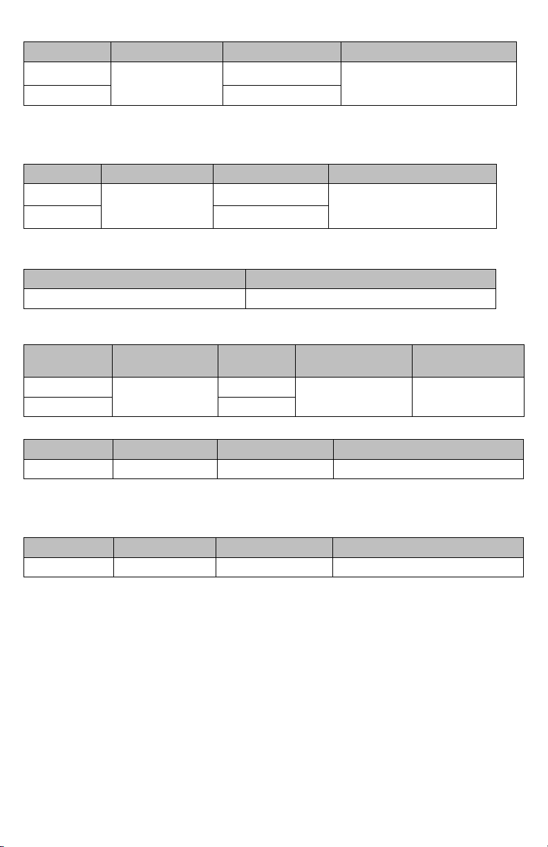
Voltage Measurement (Auto ranging)
Range Accuracy Resolution Input Impedance
15 – 310V
±(0.5%+2digit)
310 – 600V 0.4V
0.2V 300kΩ(phase-neutral)
600kΩ (phase-phase)
Voltage Anomalies Detection (Manual Selection of Range)
Voltage
Range Accuracy Resolution Input Impedance
15 – 310V
310 – 600 0.4V
±(0.5%+2digit)
0.2V 300kΩ (phase-neutral)
600kΩ (phase-phase)
Time
Accuracy (ref. to 60Hz) Resolution
±8.33ms (½ period of fundamental) 8.33ms (½ period of fundamental)
Current measurement (DM-II Plus only)
Range Accuracy Resolution Input Impedance
0.005-0.26V
0.26-1V 0.0004V
±(0.5%+2digit)
0.0001V
100kΩ 5V
Protection against
Current measurement (Using DM-CT-HTA)
Range Accuracy Resolution Protection against overloads
5 to 1000 A ±(1.5% of range) 0.1 A 600 V
Minimal Current measurable is equal to 1.5% of Clamp Full Scale
Current measurement (Using ACF-3000 SR)
Range Accuracy Resolution Protection against overloads
15 to 3000 A ±(1.5% of range) 0.1 A 600 V
Minimal Current measurable is equal to 1.5% of Clamp Full Scale
overloads
20
Page 23

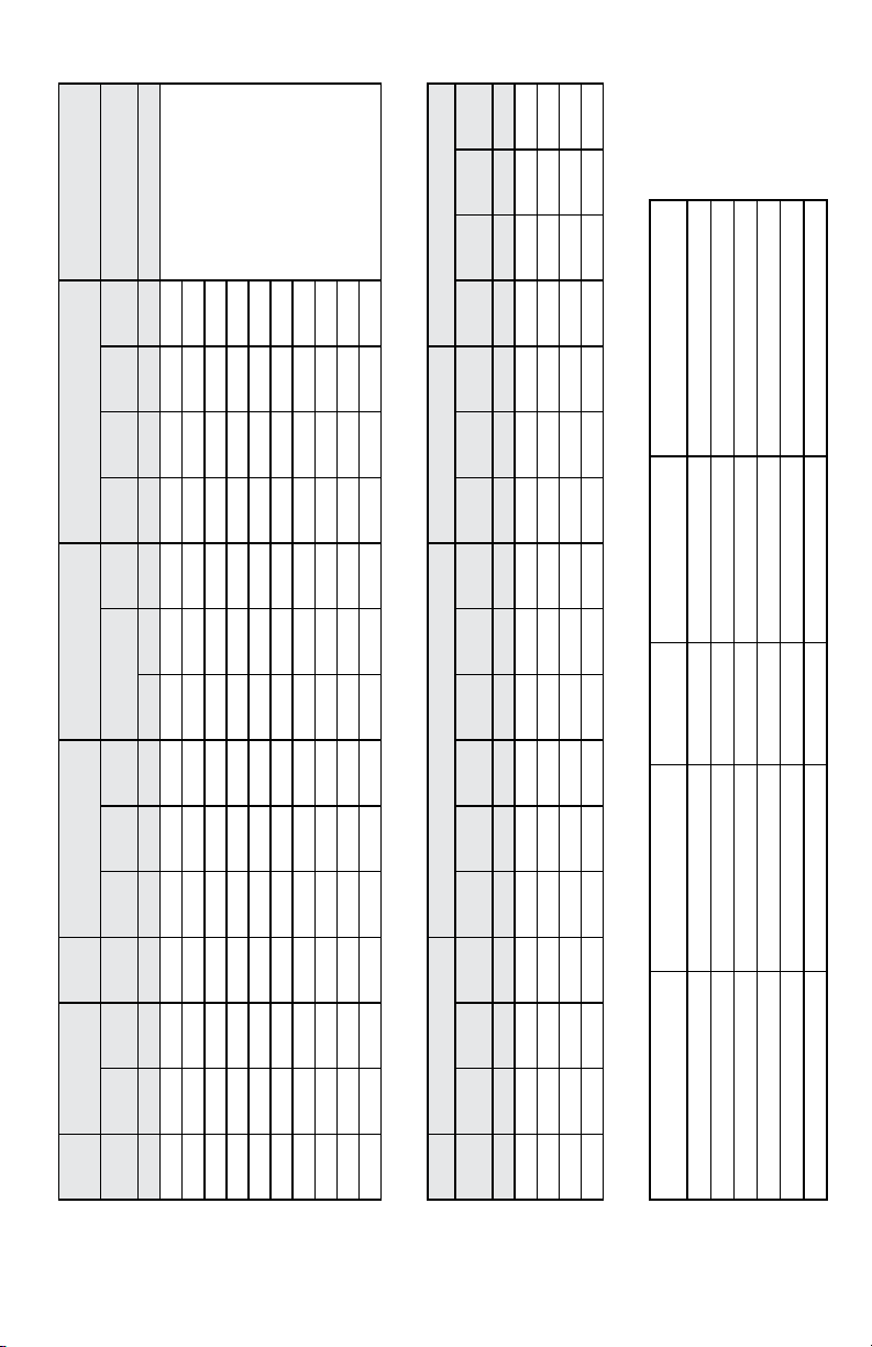
Power measurement (cosϕ: 0.5c[positive] – 0.5i[negative])
Value Ranges Accuracy Resolution
Active power 0 – 999.9W
1kW – 999.9kW
1MW – 999.9MW
Reactive power 0 – 999.9VAR
1kVAR – 999.9kVAR
1MVAR – 999.9MVAR
Apparent power 0 – 999.9VA
1kVA – 999.9kVA
±(1.5%+2digit)
1MVA – 999.9MVA
Active energy 0 – 999.9Wh
1kWh – 999.9kWh
1MWh – 999.9MWh
Reactive energy 0 – 999.9VARh
1kVARh – 999.9kVARh
1MVARh – 999.9MVARh
Cosϕ Measurement
Cosϕ Resolution Accuracy (expressed in degrees)
0 to 0.20
0.21 to 0.50 0.7
0.01
0.51 to 0.80 1
0.1W
0.1kW
0.1MW
0.1VAR
0.1kVAR
0.1MVAR
0.1VA
0.1kVA
0.1MVA
0.1Wh
0.1kWh
0.1MWh
0.1VARh
0.1kVARh
0.1MVARh
0.6
Measurement of Harmonics
Voltage
Range Accuracy Resolution
DC – 25h
26h – 33h
34h – 49h
±(5.0%+2digit)
±(10.0%+2digit)
±(15.0%+2digit)
The voltage harmonics will be null under the following threshold:
- DC: if <1V or <2% of 1st harmonic
- 1st harmonic: if <2V
- 2nd to 49th: if <1V or <2% 1st harmonic
Current
Range Accuracy Resolution
DC – 25h
26h – 33h
34h – 49h
±(5.0%+2digit)
±(10.0%+2digit)
±(15.0%+2digit)
The current harmonics will be null under the following threshold:
- DC: if <2% of 1st harmonic or < 0.2% of clamp full scale
- 1st harmonic: if < 0.2% of clamp full scale
- 2nd to 49th: if <2% 1st harmonic or < 0.2% of clamp full scale
Setting the FLEX option the DC component will be ignored.
21
0.1V
0.1A
Page 24

Frequency Measurement
Instrument set to 50Hz
Range Resolution Accuracy
47 to 53 0.1Hz ±(1.0% + 1digit)
Instrument set to 60Hz
Range Resolution Accuracy
57 to 63.6 0.1Hz ±(1.0% + 1digit)
Temperature drift
Temperature drift: 0.1 x accuracy/°C (32°F)
Safety
The instrument complies to the standards: EN 61010-1 :2001
Insulation: Class II
Pollution: 2
Over-voltage category: CAT III 370V~ (Phase-Earth)
CAT III 600V~ (Phase-Phase)
Clamps: IEC 61010-2-032 Ed. 2.0
Phase Sequence Detection: EN 61557-7:2007
Mechanical Features
Dimensions: 444.5(L) x 273.05(W) x 190.5(H) mm (17.50 (L) x 10.75 (W) x 7.50 (H))
Weight: 11.5 Lb (5.2kg)
Internal power supply: 6 batteries 1.5V D size (Alkaline) NEDA 13A, IEC L20R.
Do not use rechargeable batteries.
Battery Life: 22 hours
External power supply:
Input:
Voltage(V): 100–240V; Phase: 1; Frequency(Hz): 50–60Hz; Current(A): 0.25A; Power(VA):
12–17 VA
DC Output:
Voltage(V): 12V; Current(A): 0.42A
Use only Amprobe power supply Adapter code DMTEXTPS. This power supply will not charge
the internal supply batteries.
Display: dot matrix with backlight
Resolution: 128 x 128 dots (16384 dots)
Dot size: 0.5mm x 0.5mm
Visible area: 73mm x 73mm (2.9 x 2.9 in.)
No. of samples per period: 128
Clamp:
Opening: 53 mm (2.15 in.)
Maximum diameter of the cable: 50 mm (2.00 in.)
22
Page 25

Environment
Operating Conditions
Reference temperature: 23°C ± 1°C (73°F ± 2°F)
Operating temperature: 0°C to 50°C (32°F to 122°F)
Relative humidity: <70%
Storage temperature: -10°C to 60°C (14°F to 140°F)
Storage humidity: <80%
Location: Indoor operation, < 2000 m
Safety: LVD Meets EN61010-1:2001 and EN61010-2-032:2002, CAT III - 600V, class II and
pollution degree 2 and EN61557-1,7.
EMC: EN 61326-1:2006 This product complies with requirements of the following
European Community Directives: 2004/108/EC (Electromagnetic Compatibility) and 2006/95/
EC (Low Voltage) as amended by 93/68/EEC (CE Marking). However, electrical noise or intense
electromagnetic fields in the vicinity of the equipment may disturb the measurement circuit.
Measuring instruments will also respond to unwanted signals that may be present within the
measurement circuit. Users should exercise care and take appropriate precautions to avoid
misleading results when making measurements in the presence of electronic interference.
APPENDIX
Messages Displayed
Message Description Advices
AUTONOM: Available memory autonomy for the
CLEAR ALL? (Enter) Trying to erase all the recordings Push CANCEL to keep all
CLEAR LAST? (Enter) Trying to erase the last recording Push CANCEL to keep the
Data saved The data has been saved
DATA SIZE: Amount of stored data
HOLD The HOLD function has been activated,
Password: At least 5 minutes has passed since the
Invalid date The entered date is not correct Check the date and date
Energy Measuring The instrument is taking an energy
Memory Full The memory of the instrument is full Transfer recordings to a PC
No ext supply! A recording has been started without
recording affected
values will not be updated.
last activity of the instrument
measurement
connecting the external power supply
recordings, Push ENTER
to confirm and erase all
recordings
last recording, Push ENTER
to confirm and erase the
last recording
Push HOLD to disable this
function
Insert the password: F1, F4,
F3, F2
format
Push F1 to stop
and then clear the instrument memory
Connect the external
power supply and Push
START again.
23
Page 26

Message Description Advices
No parameter selected
A recording has been started without
selecting values to be recorded
Push START/STOP, and select at least one value from
the MENU
No Phase selected Voltage and/or current harmonics have
been selected and the corresponding
Select at least one phase
voltage and/or current
flag has been enabled (HARMONICS
ON) but no phase voltage or current has
been selected
PASSWORD ERROR The password entered is wrong Insert the password: F1, F4,
F3, F2
PASSWORD OK The password is correct
Please wait The instrument is waiting for the record-
ing to start
Recording The instrument is recording
Too many param More than 63 parameters have been
Deselect parameters
selected (harmonics included) or more
than 38 parameters with COGENERATION Flag enabled
Too many record The quantity of recorded data + Smp
exceeds the maximum allowed (35)
Transfer recordings to a PC
and then clear the instru-
ment memory
ERR: SEQ The Phase Sequence is wrong. Check the Phase Sequence
connection.
ERR: P- The active powers on the right side of
the message are negative
Check if the clamps are
properly connected, unless
co-generation is involved
ERR: SEQ & P- The active powers on the right side of
the message are negative and the Phase
Sequence is wrong.
Check if the clamps are
properly connected / check
the Phase Sequence con-
nection, unless co-genera-
tion is involved
ERR: CONNECTION The Voltage inputs are not connected
correctly.
Check the Voltage connec-
tions (see Physical Connec-
tions, Page X8)
Error Vref A Voltage reference was selected that is
not compatible with voltage input.
Check Voltage Reference
set in RECORDER CONFIG
in MENU
Error1 to Error 5 The instrument memory is damaged. Contact Amprobe for as-
sistance
24
Page 27

Recordable Parameters Symbols
Symbol Description
V1, V2, V3 RMS value of the voltage of phase 1, phase 2, phase 3 respectively
V12, V23 V31 Value of phase to phase voltages
I1, I2, I3 RMS value of the current of phase 1, phase 2, phase 3 respectively
IN RMS value of the current of the neutral
DC Continuous component of voltage or current
h01 to h49 Harmonic 01 to Harmonic 49 of voltage or current
ThdV Factor of total harmonic distortion of the voltage
ThdI Factor of total harmonic distortion of the current
Powers, Pf and cosϕ
Pt, P1, P2, P3 Values of the total active power, of phase 1, phase 2, phase 3
P12, P32 (only for 3 wires measurement) Value of the power measured by
Qt, Q1, Q2, Q3 Values of the total reactive power, of phase 1, phase 2, phase 3
Q12, Q32 (only for 3 wires measurement) Value of the power measured by
St, S1, S2, S3 Values of the total apparent power, of phase 1, phase 2, phase 3
S12, S32 (only for 3 wires measurement) Value of the power measured by
Pft, pf1, pf2, pf3 Value of the total power factors, power factors of phase 1, phase
dPft, dpf1, dpf2, dpf3 Values of the total cos, of phase 1, phase 2, phase 3 respectively
Energies
Eat, Ea1, Ea2, Ea3 Values of the total active energy, of phase 1, phase 2, phase 3
Erit, Eri1, Eri2, Eri3 Values of the total inductive reactive Energy, of phase 1, phase 2,
Erct, Erc1, Erc2, Erc3 Values of the total capacitive reactive Energy, of phase 1, phase 2,
Est, Es1, Es2, Es3 Values of the total Apparent Energy, of phase 1, phase 2, phase 3
respectively
the Wattmeter 1-2 and 3-2 respectively
respectively
the VARmeter 1-2 and 3-2 respectively
respectively
the VAmeter 1-2 and 3-2 respectively
2, phase 3 respectively
respectively
phase 3 respectively
phase 3 respectively
respectively
25
Page 28
B=+/- 3.0275
Temperature (E3) Percent age Operating Error
Type of Test
Test in accordance with
Relevant parts of IEC 61557
Voltage(E2)
Infuence Of Supply
Designated Code
)) B Part 1, 4.1
2
3
+ E
2
2
+ E
2
1
Reference conditions or
1.13 0 0 1.65
A (-)90˚ (+)90˚ E1 Batter y Supply E2 0˚C 35˚C 50˚C E3 (B)
Reading
Value
A 49 50 51 59 60 61 0˚C 50˚C E3 (B)
Reading
Value
Intrinsic Error Influence of Frequency Temperature (E3) Percentage Operating Error
specified operating range
Intrinsic Error Position(E1)
Input
Value
Input
Value
Intrinsic Error Reference conditions A Part 1, 6.1 R
Position Reference position ±90˚ E1 Par t 1, 4.2 R
Supply Voltage E2 Part 1, 4.2, 4.3 R
Temperature 0˚C and 50˚C E3 Part 1, 4.2 T
Range [V] [V] % % 6. 2V 8.5V % % %
V1 263 26 4 0.38 264 264 0 264 264 0
V2 263 265 0.76 265 265 0 265 265 0
V3 263 267 1.13 267 267 0 267 267 0
V13 456 460 0.88 460 460 0 460 460 0
Operating Error: Voltage Measurement
V12 456 459 0.65 459 459 0 459 459 0
V23 400 399.9 406 408.4 1.65
V23 456 461 1.1 4 61 461 0 4 61 461 0
V12 400 398.5 404.4 407 1.1
V13 400 400.2 406.6 408.9 1.65
Operating Error: Current Measurement
Range [V] [A] % % %
I1 1.0057 1010 0.43 860 1010 840 926 999 853
I2 1.0057 1010 0.43 860 1010 840 926 999 853
I3 1.0057 1010 0.43 860 1010 840 926 999 853
In 1.0057 3020 2563 1010 2503 2785 2996 2554
Intrinsic Error Of Influence quantity
Notes:
Operating Error B=±( |A| + 1.15 X √(E
A = intrinsic error En = Variations R = routine test T = typ e test B[%] = ±(B / fiducial value) X 100%
26
Page 29
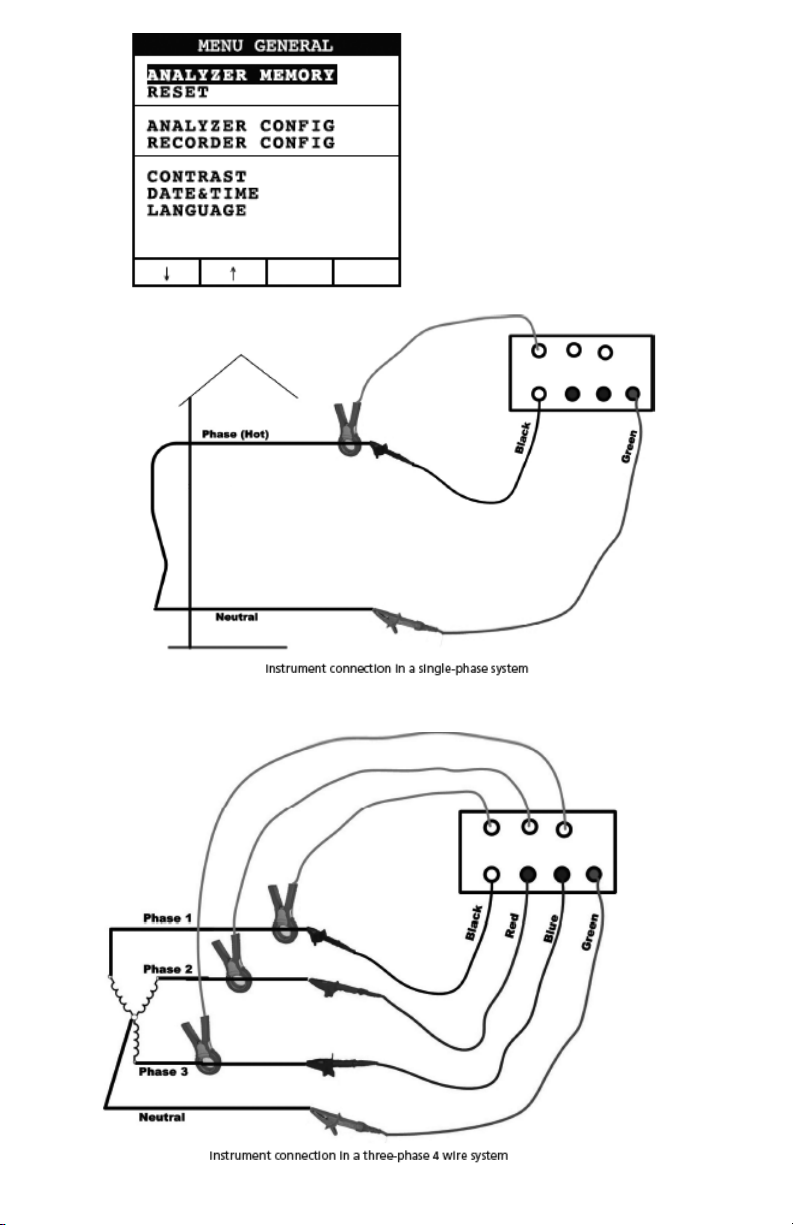
Fig. 1
Fig. 2
Fig. 3
27
Page 30
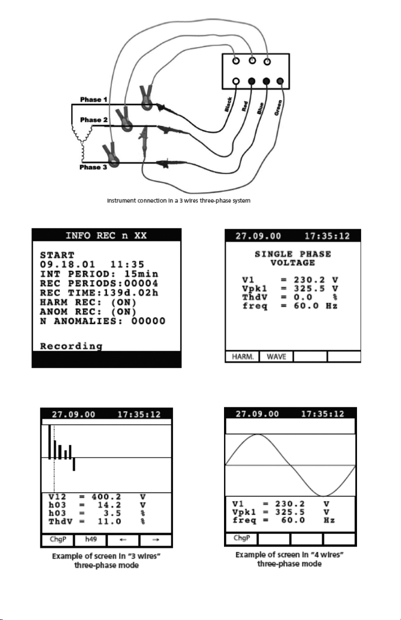
Fig. 4
Fig. 5
Fig. 7
Fig. 6
Fig. 8
28
Page 31

Fig. 9
Fig. 10
Fig. 11
Fig. 13
Fig. 12
Fig. 14
29
Page 32

Fig. 15
Fig. 16
Fig. 17
Fig. 19
Fig. 18
Fig. 20
30
Page 33

Fig. 21
Fig. 22
Fig. 23
Fig. 24
Fig. 25
31
Page 34

32
Page 35

DM-II PLUS
Enregistreur de qualité
de puissance
Mode d’emploi
DMIIPLUS_Rev004
© 2008 Amprobe Test Tools.
Tous droits réservés.
Français
33
Page 36

Limites de garantie et de responsabilité
Amprobe garantit l’absence de vices de matériaux et de fabrication de ce produit pendant une
période d’un an prenant effet à la date d’achat. Cette garantie ne s’applique pas aux fusibles,
aux piles jetables ni à tout produit mal utilisé, modifié, contaminé, négligé ou endommagé par
accident ou soumis à des conditions anormales d’utilisation et de manipulation. L’obligation
de garantie d’Amprobe est limitée, au choix d’Amprobe, au remboursement du prix d’achat
ou à la réparation/remplacement gratuit d’un produit défectueux. Les distributeurs agréés
par Amprobe ne sont pas autorisés à appliquer une garantie plus étendue au nom d’Amprobe.
Pour bénéficier de la garantie, renvoyez le produit accompagné d’un justificatif d’achat auprès
d’un centre de services agréé par Amprobe Test Tools ou d’un distributeur ou d’un revendeur
Amprobe. Voir la section Réparation pour tous les détails. La présente garantie est le seul et
exclusif recours toutes autres garanties, explicites, implicites ou statutaires, notamment le
cas échéant les garanties de qualité marchande ou d’adaptation a un objectif particulier sont
exclues par les présentes. Amprobe, la société mère ou ses filiales ne peuvent en aucun cas
être tenues responsables des dommages particuliers, indirects, accidentels ou consécutifs,
ni d’aucuns dégâts ou pertes de données, sur une base contractuelle, extra-contractuelle ou
autre. Etant donné que certaines juridictions n’admettent pas les limitations d’une condition
de garantie implicite, ou l’exclusion ou la limitation de dégâts accidentels ou consécutifs, il se
peut que les limitations et/ou les exclusions de cette garantie ne s’appliquent pas à votre cas.
Réparation
Tou s les outils de test renvoyés pour un étalonnage ou une réparation couverte ou non par
la garantie doivent être accompagnés des éléments suivants : nom, raison sociale, adresse,
numéro de téléphone et justificatif d’achat. Ajoutez également une brève description
du problème ou du service demandé et incluez les cordons de mesure avec l’appareil. Les
frais de remplacement ou de réparation hors garantie doivent être acquittés par chèque,
mandat, carte de crédit avec date d’expiration, ou par bon de commande payable à l’ordre de
Amprobe® Test Tools.
Remplacements et réparations sous garantie – Tous pays
Veuillez lire la déclaration de garantie et vérifier la pile avant de demander une réparation.
Pendant la période de garantie, tout outil de test défectueux peut être renvoyé auprès de
votre distributeur Amprobe® Test Tools pour être échangé contre un produit identique ou
similaire. Consultez la section « Where to Buy » sur le site www.amprobe.com pour obtenir la
liste des distributeurs dans votre région. Au Canada et aux Etats-Unis, les appareils devant être
remplacés ou réparés sous garantie peuvent également être envoyés dans un centre de services
Amprobe® Test Tools (voir les adresses ci-dessous).
Remplacements et réparations hors garantie – Canada et Etats-Unis
Les appareils à réparer hors garantie au Canada et aux Etats-Unis doivent être envoyés dans
un centre de services Amprobe® Test Tools. Appelez Amprobe® Test Tools ou renseignez-
vous auprès de votre lieu d’achat pour connaître les tarifs en vigueur de remplacement ou de
réparation.
Aux Etats-Unis Au Canada
Amprobe Test Tools Amprobe Test Tools
Everett, WA 98203 E-U Mississauga, ON L4Z 1X9 Canada
Tel: 877-993-5853 Tel: 905-890-7600
Fax: 425-446-6390 Fax: 905-890-6866
Remplacements et réparations hors garantie – Europe
Les appareils européens non couverts par la garantie peuvent être remplacés par votre
distributeur Amprobe® Test Tools pour une somme nominale. Consultez la section « Where to
Buy » sur le site www.amprobe.com pour obtenir la liste des distributeurs dans votre région.
Adresse postale européenne*
Amprobe® Test Tools Europe
Beha-Amprobe GmbH
In den Engematten 14
79286 Glottertal, Germany
Tel.: +49 (0) 7684 8009 – 0
*(Réservée à la correspondance – Aucune réparation ou remplacement n’est possible à cette
adresse. Nos clients européens doivent contacter leur distributeur.)
34
Page 37

DM-II PLUS
Enregistreur de qualité de puissance
Précautions et sécurité ........................................................................................................................37
Symboles ..........................................................................................................................................37
Consignes de sécurité......................................................................................................................37
Mises en garde et précautions .......................................................................................................37
Déballage et inspection ......................................................................................................................38
Appareil : Description ..................................................................................................................... 38
Clavier : Description ........................................................................................................................ 39
Affichage : Description ................................................................................................................... 39
Menu General – Settings (Général - Paramètres) (voir la figure 1) ..............................................39
Paramètres par défaut ....................................................................................................................40
Connexions du Systeme ...................................................................................................................... 41
Fonctionnement ..................................................................................................................................41
Système monophasé (voir la figure 2) ...........................................................................................41
Système triphasé à quatre fils (voir la figure 3) ............................................................................41
Système triphasé à trois fils (voir la figure 4) ................................................................................ 42
Techniques de mesure .........................................................................................................................42
Procédure recommandée pour un enregistrement ......................................................................42
Pour démarrer un enregistrement .................................................................................................42
Pendant un enregistrement (voir la figure 5) ...............................................................................43
Arrêt d’un enregistrement .............................................................................................................43
Connexion avec un PC.....................................................................................................................43
Evaluation des valeurs des paramètres ..............................................................................................44
Voltage (Tension) (voir la figure 6) ................................................................................................44
Mode HARM. (harmonique) (voir la figure 7) ...............................................................................44
Mode WAVE (onde) (voir la figure 8) ............................................................................................ 44
Current (courant) (voir la figure 9) ................................................................................................45
Power (puissance) (voir la figure 12)..............................................................................................46
Energy (énergie) (voir la figure 15) ................................................................................................47
Analyzer Config (configuration de l’analyseur), Recorder Config (configuration de l’enregistreur)
et Analyzer Memory (mémoire de l’analyseur) .................................................................................47
Configuration de l’analyseur (voir la figure 16) ............................................................................47
Recorder Configuration (Configuration de l’enregistreur) .......................................................... 48
Analyzer Memory (mémoire de l’analyseur) (voir la figure 25) ................................................... 52
Entretien et réparation ......................................................................................................................52
Changement des piles .........................................................................................................................53
35
Page 38

DM-II PLUS
Enregistreur de qualité de puissance
Table des matières (suite)
Specifications techniques ....................................................................................................................53
Fonctionnalités ................................................................................................................................53
Environnement ................................................................................................................................56
Annexe .................................................................................................................................................56
Messages affichés ............................................................................................................................56
Symboles des paramètres enregistrables .......................................................................................58
36
Page 39

PRÉCAUTIONS ET SÉCURITÉ
Symboles
Pile
Double isolation
Courant alternatif
Conforme aux normes australiennes.
Ne pas mettre ce produit au rebut parmi
les déchets ménagers.
L’application et le retrait de la pince à
proximité de conducteurs sous tension
dangereuse sont autorisés.
Se reporter au mode d’emploi
Tension dangereuse
Prise de terre
Signal sonore
Conforme aux directives de l’UE
Consignes de sécurité
Le dispositif DM II Plus est conforme aux normes EN61010-1:2001; EN61010-2-032:2002 ; •
CAT III 600 V, classe II et niveau de pollution 2 et EN 61557-7.
Cet appareil est certifié conforme à la norme EN61010-1 pour les installations de catégorie III •
(600 V). Il est recommandé pour les installations fixes et les équipements au niveau
distribution, ainsi que pour les installations de catégories inférieures, mais il n’est pas
destiné aux lignes du réseau d’alimentation électrique principale, aux lignes aériennes ou
aux systèmes câblés.
Ne pas dépasser les limites de surcharge maximum par fonction (voir les caractéristiques •
techniques) ou les limites indiquées sur l’appareil lui-même. Ne jamais appliquer plus de
600 Vca efficaces de phase à phase ou 370 Vca de phase à la terre.
Mises en garde et précautions
Avant et après les mesures de tensions dangereuses, tester la fonction de tension sur une source •
connue, une tension secteur p. ex., pour déterminer le bon fonctionnement du multimètre.
Inspecter l’appareil de mesure, les pinces, les fils de test et les accessoires avant toute •
utilisation. Ne pas utiliser de pièce endommagée.
Ne jamais se relier à la terre en prenant des mesures. Ne pas toucher aux éléments de circuit •
exposés ni aux pointes des sondes de test.
Ne pas utiliser l’appareil dans une atmosphère explosive.•
Pour réduire le risque d’incendie ou d’électrocution, ne pas exposer cet appareil à l’humidité •
ou à la pluie.
Le multimètre est destiné à être utilisé à l’intérieur uniquement. Pour éviter les chocs •
électriques, observer les précautions de sécurité appropriées en intervenant sur des tensions
supérieures à 60 Vcc, à 42,4 V de pointe ou à 30 Vca eff. Ces niveaux de tension présentent
un risque d’électrocution pour l’utilisateur.
Garder les mains/doigts derrière les collerettes de protection qui indiquent les limites de •
sécurité du multimètre et des cordons pendant la mesure.
Inspecter les cordons de mesure, les connecteurs et les sondes en recherchant un •
endommagement de l’isolant ou les parties métalliques exposées avant d’utiliser
l’instrument. Remplacer immédiatement l’élément si des défauts sont détectés.
Cette pince multimètre est destinée à être retirée ou appliquée aux conducteurs sous •
tension dangereuse non isolés. Utiliser des équipements de protection individuelle si des
pièces sous tension dangereuse risquent d’être accessibles.
User de précautions extrêmes en mesurant une tension > 20 V // un courant > 10 mA // les •
lignes d’alimentation secteur avec charges inductives // les lignes d’alimentation secteur
pendant les orages électriques // un courant alors que le fusible a sauté dans un circuit avec
une tension en circuit ouvert > 1 000 V // lors d’une intervention sur un appareil à écran
cathodique.
Retirer les cordons de mesure avant d’ouvrir le boîtier pour changer la pile.•
Pour éviter de fausses lectures qui pourraient provoquer une électrocution ou des blessures •
corporelles, remplacer les piles lorsque le témoin de piles déchargées apparaît.
Pour éviter tout risque d’électrocution, ne pas utiliser la fonction HOLD pour déterminer si •
un circuit est sous tension. Les lectures instables ne seront ni capturées, ni affichées.
Pour obtenir des mesures exactes après un long entreposage dans un lieu aux conditions •
environnementales rigoureuses, attendre que l’appareil se stabilise à ses conditions normales.
37
Page 40

DÉBALLAGE ET INSPECTION
CAT III 600V MAX
v
V1 V2 V3
C
O
M
1
2
4
3
I1
I2
I3
12V dc
250 mA
+ -
1 2 3 4
Assurez-vous que l’appareil n’a pas subi de dommage pendant le transport. Si vous détectez
des problèmes, avertissez le transporteur. Assurez-vous que tous les accessoires et les pièces
figurant ci-dessous sont inclus. En cas de problème, contactez votre concessionnaire.
Description Nom du modèle
Appareil DM-II PLUS
Alimentation électrique externe 12 V cc DMT-EXTPS
3 pinces-multimètre 1000 A/1 V DM-CT-HTA (code 1 pcs)
4 câbles et pinces crocodiles pour mesure de tension KITENERGY3
1 CD de logiciel DS2.3
Câble série C232NG1
Appareil : Description
➊
➋
➊ Sortie série RS232
➌
➍
➎
Affichage
➋
Prise d’alimentation
➌
électrique externe 12 V cc
Entrées de tension et de
➍
courant
Clavier
➎
Entrées de tension
Entrée phase 1
➊
Entrée phase 2
➋
Entrée phase 3
➌
Entrée phase
➍
Entrées de courant
Entrée de courant phase 1
➊
Entrée de courant phase 2
➋
Entrée de courant phase 3
➌
Entrée de puissance dc
38
➍
Page 41

Clavier : Description
ON/OFF : Mise sous tension – mise hors tension / Rétroéclairage activé
F1, F2, F3, F4: Touches de navigation. La fonction spécifique apparaît au bas de l’écran.
Voltage (tension),
Current (courant),
Power (puissance),
Energy (énergie) : Allez à la mesure correspondante.
MENU : Permet de vérifier et de modifier les paramètres.
CANCEL (annuler) : Renvoie à un écran précédent. Quitte un menu ou un sous-menu.
ENTER/HOLD Touche à double fonction :
(entrée/maintien) :
ENTER : Confirme les paramètres.
HOLD (Maintien d’affichage) : Empêche la mise à jour des valeurs.
SAVE (enregistrer) : Pour enregistrer dans la mémoire de l’appareil un enregistrement de
START/STOP
(démarrer/arrêter) : Démarre/arrête un enregistrement.
(arrêt automatique après 5 secondes)
La fonction est désactivée lors de l’enregistrement ou de la mesure
de l’énergie. Quand elle est activée, il est impossible d’effectuer un
enregistrement ou une mesure.
« Smp ». La fonction est désactivée au cours d’un enregistrement.
Affichage : Description
Affichage initial
A la mise sous tension du DM-II Plus, l’affichage montre cet écran initial.
L’affichage est un module graphique avec une résolution de 128 x 128 pixels (globalement
16384 pixels).
SN – Numéro de série de l’appareil
VER – Version logicielle du microprogramme
BAUD RATE – Vitesse de transmission par l’E/S série
Menu General – Settings (Général - Paramètres) (voir la figure 1)
Appuyez sur MENU pour accéder à l’écran MENU GENERAL.
Appuyez sur ENTER pour enregistrer les changements ou sur CANCEL pour revenir au
MENU précédent.
Appuyez sur F1 ou F2 pour mettre en surbrillance les sous-menus, sur F3 ou F4 pour modifier
les paramètres et sur + ou – pour changer les valeurs.
REMARQUE : Le Menu n’est pas disponible pendant un enregistrement ou une mesure
d’énergie en temps réel.
ANALYZER MEMORY (mémoire de l’analyseur) – Affiche la mémoire de l’appareil. Voir la
section 6.3.
RESET (réinitialiser) – Change tous les paramètres à leur valeur par défaut. La mémoire n’est
pas effacée.
39
Page 42

ANALYZER CONFIG (configuration de l’analyseur) – Définit le type de système électrique sous
test, la fréquence fondamentale, la intervalle du courant, le type de pince, le rapport de
tension du transformateur et un mot de passe. Voir la section 6.1.
RECORDER CONFIG (configuration de l’enregistreur) – Permet de vérifier et de modifier jusqu’à
64 paramètres d’enregistrement, activer l’enregistrement automatique, définir la valeur de la
période d’intégration, la fonction de détection de chute et de pic de tension et la fonction de
détection des harmoniques. Voir la section 6.2.
CONTRAST – Change le contraste de l’affichage.
DATE&TIME (date et heure) – Règle la date et l’heure. Change le format de la date.
LANGUAGE – Change la langue de l’affichage.
Paramètres par défaut
L’appareil est pré-réglé avec une configuration générale qui convient dans la plupart des cas.
Pour régler ces paramètres, voir la section 6.
ANALYZER CONFIG (configuration de l’analyseur) :
Frequency (fréquence) : 60 Hz
Full scale of the clamps (pleine échelle des pinces) : 1000 A
Transforming ratio of volt metric transformers (transformation du rapport des
transformateurs volts-métriques : 1
Type of electrical equipment (type de l’équipement électrique) : Four wires (quatre fils)
Password (mot de passe) : activé
RECORDER CONFIG (configuration de l’enregistreur) :
Start (démarrage) : Manuel (après appui sur la touche START/STOP, l’enregistrement
démarre après 1 minute à la marque 00 seconde.)
Stop (arrêt) : Manuel
Integration period (durée d’intégration) : 15 min
Recording of harmonics (enregistrement des harmoniques) : Activé
Recording of Sag and Surge (enregistrement des chutes et des pics) : Activé
Voltage Reference for Sag and Surge detection (référence de tension pour détection des
chutes et des pics) : 230 V
Upper Limit for Sag and Surge detection (limite supérieure pour la détection des chutes et
des pics) : 6 %
Upper Limit for Sag and Surge detection (limite inférieure pour la détection des chutes et
des pics) : 10 %
Selected voltages (tensions sélectionnées) : V1, V2, V3
Selected v
Selected currents (courants sélectionnés) : I1, I2, I3, IN
Selected
CO-GENERATION : Désactivée
Powers, Pf et cosϕ sélectionnés Pt, P1, P2, et P3
Energies : Eat, Ea1, Ea2, Ea3
oltage harmonics (Harmoniques de tension sélectionnés) : Thd (DHT), 01, 03, 05, 07
current harmonics (harmoniques de courant sélectionnés) : Thd (DHT), 01, 03, 05, 07
Qti, Q1i, Q2i, Q3i
Qtc, Q1c, Q2c, Q3c
St, S1, S2, S3
Pft, Pf1, Pf2, Pf3
dpft, dpf1, dpf2, dpf3
Erit, Eri1, Eri2, Eri3
Erct, Erc1, Erc2, Erc3
Est, Es1, Es2, Es3
40
Page 43

CONNEXIONS DU SYSTEME
Attention : Si possible, avant de brancher l’appareil à l’équipement à tester, mettez cet
équipement hors tension.
Ne mesurez pas des tensions dépassant ces limites car cela pourrait vous exposer à des
situations dangereuses ou endommager l’appareil ou/et ses composants.
FONCTIONNEMENT
Système monophasé (voir la figure 2)
Attention : La tension maximum entre les entrées L1 et COM est 370 V~ phase-terre.
Branchez les câbles et la pince comme indiqué à la fig. 2.1.
Dans le menu ANALYZER CONFIG, réglez SYSTEM (système) à SINGLE PHASE (monophasé).2.
Réglez les paramètres Frequency (fréquence), Current Range (intervalle de courant), Clamp 3.
type (type de pince) et TV (rapport TV).
Appuyez sur ENTER pour accepter les changements.4.
Appuyez sur CANCEL (annuler) pour revenir à l’affichage du dernier écran d’analyse.5.
Appuyez sur POWER (puissance) pour vérifier les points suivants :6.
La direction de la pince : La puissance active P doit être positive. Si elle est négative, a.
tournez la pince.
La séquence de phase : 100b.
La valeur de la Pf de chaque phase ne doit pas être inférieure à 0,4. Si la Pf est inférieure c.
à 0,4, vérifiez que la tension de phase est associée au multimètre à pince correct (V1 est
associée au multimètre à pince nº1).
Appuyez sur la touche VOLTAGE, CURRENT, POWER ou ENERGY pour le type d’analyse. 7.
Pour interrompre la mise à jour en temps réel des valeurs affichées, appuyez sur la
touche HOLD.
Pour enregistrer les valeurs, voir la section 6.2.8.
Système triphasé à quatre fils (voir la figure 3)
Attention : La tension maximale entre les entrées V1, V2, V3 et COM est de CAT III 600 V~
phase-phase 370 V~ phase-terre.
Branchez les câbles et la pince comme indiqué à la fig. 3. 1.
Dans le menu ANALYZER CONFIG, réglez SYSTEM (système) à 3PH4W.2.
Réglez les paramètres Frequency (fréquence), Current Range (intervalle de courant), Clamp 3.
type (type de pince) et TV (rapport TV).
Appuyez sur ENTER pour accepter les changements.4.
Appuyez sur CANCEL (annuler) pour revenir à l’affichage du dernier écran d’analyse.5.
Appuyez sur POWER (puissance) pour vérifier les points suivants :6.
La direction de la pince. La puissance active P doit être positive. Si elle est négative, a.
tournez la pince.
Séquence de phase : 123b.
La valeur de la Pf de chaque phase ne doit pas être inférieure à 0,4. Si la Pf est inférieure c.
à 0,4, vérifiez que la tension de phase est associée au multimètre à pince correct (V1 est
associée au multimètre à pince nº1, V2 est associée au multimètre à pince nº2 et V3 est
associée au multimètre à pince nº3).
7. Appuyez sur la touche VOLTAGE, CURRENT, POWER ou ENERGY pour le type d’analyse.
8. Pour interrompre la mise à jour en temps réel des valeurs affichées, appuyez sur la
touche HOLD.
9. Pour enregistrer les valeurs, voir la section 6.
41
Page 44

Système triphasé à trois fils (voir la figure 4)
Attention : La tension maximale entre les entrées V1, V2, V3 et COM (V2) est CAT III
600 V~ phase-phase.
REMARQUE : Le câble vert (neutre) est connecté au câble rouge sur la phase 2.
Branchez les câbles et les pinces comme indiqué à la fig. 4. 1.
Dans le menu ANALYZER CONFIG, réglez SYSTEM (système) à 3PH4W.2.
Réglez les paramètres Frequency (fréquence), Current Range (intervalle de courant), Clamp 3.
type (type de pince) et TV (rapport TV).
Appuyez sur ENTER pour accepter les changements.4.
Appuyez sur POWER (puissance) pour vérifier les points suivants :5.
La direction de la pince. La puissance active P doit être positive. Si elle est négative, a.
tournez la pince.
La valeur de la Pf de chaque phase ne doit pas être inférieure à 0,4. Si la Pf est inférieure b.
à 0,4, vérifiez que la tension de phase est associée au multimètre à pince correct (V12 est
associée au multimètre à pince nº1, V32 est associée au multimètre à pince nº2 et V31 est
associée au multimètre à pince nº3).
6. Appuyez sur CANCEL (annuler) pour revenir à l’affichage du dernier écran d’analyse.
7. Appuyez sur la touche VOLTAGE, CURRENT, POWER ou ENERGY pour le type d’analyse.
8. Pour interrompre la mise à jour en temps réel des valeurs affichées, appuyez sur la
touche HOLD.
9. Pour enregistrer les valeurs, voir la section 6.2.
TECHNIQUES DE MESURE
Attention : Pour les enregistrements, utilisez TOUJOURS l’alimentation
électrique externe.
En cas de coupure de l’alimentation externe au cours d’un enregistrement, la pile interne sera
utilisée.
Il est recommandé de TOUJOURS insérer un nouveau jeu de piles avant un enregistrement de
longue durée.
Procédure recommandée pour un enregistrement
Vérifiez et modifiez les paramètres. Voir la section 6.1. 1.
Appuyez sur la touche VOLTAGE, CURRENT, POWER ou ENERGY pour le type d’analyse.2.
Branchez l’appareil au système électrique à tester.3.
Evaluez les valeurs des paramètres. Voir la section 5.4.
Si vous voulez enregistrer :5.
Décidez de ce que vous voulez enregistrer eta.
Appuyez sur MENU pour régler les paramètres (voir la section 2.3 pour les paramètres par b.
défaut). Voir la section 6.
Branchez l’alimentation électrique externe.6.
Faites démarrer l’enregistrement en appuyant sur START/STOP.7.
Pour démarrer un enregistrement
Manuellement – Appuyez sur la touche START/STOP. Quand la minuterie affiche 00 secondes,
l’enregistrement démarre.
Automatiquement –
Appuyez sur MENU.1.
Sélectionnez RECORDER CONFIG en utilisant les touches haut 2. et bas . Appuyez
sur ENTER.
42
Page 45

Appuyez sur + ou – pour passer de MAN à AUTO. 3.
Appuyez sur 4. pour sélectionner le mois, le jour, l’année, l’heure, les minutes et les
secondes.
Appuyez sur + ou – pour définir la date et l’heure de début de l’enregistrement.5.
Appuyez sur 6. pour sélectionner STOP et appuyez la touche sur + ou – pour passer de
MAN à AUTO.
Appuyez sur 7. pour sélectionner le mois, le jour, l’année, l’heure, les minutes et
les secondes.
Appuyez sur + ou – pour définir la date et l’heure d’arrêt de l’enregistrement.8.
Appuyez sur 9. pour sélectionner INT PERIOD. Appuyez sur + ou – pour changer
la période.
Appuyez sur 10. pour sélectionner HARM REC. Appuyez sur + ou – pour l’activer ou
le désactiver.
Appuyez sur 11. pour sélectionner ANOM REC. Appuyez sur + ou – pour l’activer ou
le désactiver.
Appuyez deux fois sur CANCEL pour revenir à l’écran précédent.12.
Appuyez sur la touche START/STOP. L’appareil reste alors en mode d’attente jusqu’à la date 13.
et l’heure définies.
Remarque : N’oubliez pas d’appuyer sur la touche START/STOP sinon l’enregistrement ne
démarre pas.
Pendant un enregistrement (voir la figure 5)
Appuyez sur MENU pour afficher l’écran INFO. Appuyez sur CANCEL pour revenir à
l’écran précédent.
Arrêt d’un enregistrement
Si l’option « PASSWORD » est activée (Section 6), appuyez sur F1, F4, F3, F2 dans
les 10 secondes pour activer le MENU. Puis, appuyez sur START/STOP (pour arrêter
l’enregistrement) ou sur F2 (pour les mesures d’énergie).
Connexion avec un PC
Raccordez l’appareil au PC14.
Le câble RS232 et le logiciel Download Suite sont nécessaires pour transférer les •
données vers un ordinateur PC. Le port RS232 est situé sur la partie supérieure droite
de l’instrument. Il existe également un kit de conversion USB (RS-USB) disponible
pour les PC sans port RS232.
Mettez l’appareil sous tension et patientez jusqu’à la disparition de l’écran Initial.•
Branchez le câble RS232 au multimètre.•
Branchez l’autre extrémité du câble à la sortie série du PC.•
Installez le logiciel Download Suite15.
Introduisez le cédérom Download Suite dans le lecteur de cédérom du PC.•
Pour installer le logiciel, respectez les instructions affichées.•
Fonctionnement 16.
Ouvrez le programme en double cliquant sur l’icône du programme Download Suite.•
Cliquez sur WORK WITH INSTRUMENT (Utiliser l’appareil), puis cliquez sur NEXT •
(Suivant).
Sélectionnez DM-II Plus et cliquez sur NEXT.•
Sélectionnez Program device et cliquez sur NEXT. Cliquez à nouveau sur NEXT pour •
ouvrir l’écran Programming (programmation).
Configurez les paramètres et cliquez sur OK pour lancer l’enregistrement.•
43
Page 46

Pour télécharger le fichier à partir de l’appareil, cliquez sur • FILE > NEW DOWNLOAD
ou appuyez sur F2 sur votre clavier.
Suivez les instructions, puis cliquez sur NEXT.•
Pour démarrer un nouvel instrument virtuel, cliquez sur • FILE > NEW VIRTUAL
INSTRUMENT ou appuyez sur F3 sur le clavier.
Suivez les instructions, puis cliquez sur NEXT.•
Cliquez sur Visualizations pour sélectionner le multimètre numérique, le graphique •
historique générique ou le tableau historique générique. Sélectionnez les paramètres
à visualiser, puis cliquez sur OK.
Remarque : Consultez l’aide du programme Download Suite pour d’autres informations.
EVALUATION DES VALEURS DES PARAMÈTRES
Appuyez sur VOLTAGE, CURRENT, POWER, ou ENERGY pour afficher l’écran associé.
Appuyez sur SAVE pour enregistrer un enregistrement de mémoire Smp contenant les valeurs
instantanées des entrées de tension et de courant.
Appuyez sur la touche ENTER/HOLD pour interrompre la mise à jour en temps réel des valeurs
affichées. Appuyez à nouveau pour continuer l’affichage des valeurs en temps réel.
Veuillez consulter l’annexe pour connaître les définitions des messages affichés sur l’appareil.
Voltage (Tension) (voir la figure 6)
Affiche en temps réel la valeur efficace de la tension ca/cc, la valeur de crête et la valeur DHT
(distorsion harmonique totale) de toutes les tensions de phase, leurs formes d’onde et leur
spectre d’harmoniques.
Mode HARM. (harmonique) (voir la figure 7)
Appuyez sur F1 pour afficher le mode HARMONIC de la tension.
Affiche les harmoniques de la tension de phase ou de la tension phase-à-phase. Les
histogrammes représentent le contenu des harmoniques de la tension sous test.
REMARQUE : La valeur de la première harmonique h01 (fondamental à 60 Hz) n’est pas
représentée dans l’échelle avec les autres harmoniques afin d’optimiser l’affichage pour
ces dernières.
Quand la tension et le courant sont mesurés par l’instrument et que les harmoniques
deviennent négatives (en dessous de l’axe horizontal), de telles indications font référence aux
harmoniques de la tension générées par la charge.
Appuyez sur F1 (ChgP) (mode triphasé seulement) pour afficher les harmoniques des autres
tensions de phase.
Appuyez sur F2 pour afficher les harmoniques h01 à h24 (h24 est représenté) ou h25 à h49
(h49 est représenté).
Appuyez sur F3 ou F4 pour sélectionner une autre harmonique à afficher.
Mode WAVE (onde) (voir la figure 8)
Affiche la forme d’onde de la tension de phase ou de la tension phase-à-phase.
Appuyez sur F2 pour afficher le mode WAVE de la tension.
Appuyez sur F1 (ChgP) (pour les modes triphasés seulement) pour afficher des valeurs pour
une phase différente.
Symbole de tension Description
V1, V2, V3
V12, V23 ou V32, V31 Valeur efficace des tensions phase à phase
Valeur efficace de la tension de phase 1, phase 2, phase 3
respectivement
44
Page 47

Symbole de tension Description
Vpk1, Vpk2, Vpk3, Vpk12,
Vpk32
h01 à h49 Harmonique 01 à harmonique 49
ThdV Facteur de distorsion harmonique totale de la tension
freq Fréquence du réseau
Phseq
Valeur de crête de la tension phase 1, phase 2, phase 3 et de
la tension phase à phase 12 et 32 respectivement
Indicateur de séquence de phase
“123” correct
“132” inversé
“023” tension nulle sur le fil noir
“103” tension nulle sur le fil rouge
“120” tension nulle sur le fil bleu
“100” tension nulle sur les fils rouge et bleu
“020” tension nulle sur les fils noir et bleu
“020” tension nulle sur les fils noir et rouge
Current (courant) (voir la figure 9)
Affiche en temps réel la valeur efficace du courant ca/cc, la valeur de crête et la valeur DHT
(distorsion harmonique totale) des courants triphasés, leurs formes d’onde et leur spectre
d’harmoniques.
Mode HARM. (harmonique) (voir la figure 10)
Appuyez sur F1 pour afficher le mode HARMONIC du courant.
Affiche les harmoniques des courants de phase. Les histogrammes représentent le
contenu des harmoniques du courant sous test.
REMARQUE : La valeur de la première harmonique h01 (fondamental à 60 Hz) n’est pas
représentée dans l’échelle avec les autres harmoniques afin d’optimiser l’affichage pour
ces dernières.
Quand la tension et le courant sont mesurés par l’instrument et que les harmoniques
deviennent négatives (en dessous de l’axe horizontal), de telles indications font référence
aux harmoniques de la tension générées par la charge.
Appuyez sur F1 (ChgP) (mode triphasé seulement) pour afficher les harmoniques des
autres tensions de phase.
Appuyez sur F2 pour afficher les harmoniques h01 à h24 (h24 est représenté) ou h25 à h49
(h49 est représenté).
Appuyez sur F3 ou F4 pour sélectionner une autre harmonique à afficher.
Mode WAVE (onde) (voir la figure 11)
Appuyez sur F2 pour afficher le mode WAVE du courant. Il affiche la forme d’onde des
courants de phase.
Appuyez sur F1 (ChgP) (pour les modes triphasés seulement) pour afficher des valeurs
pour une phase différente.
Symbole du
courant
I1, I2, I3 Valeur efficace du courant de phase 1, phase 2, phase 3 respectivement
IN Valeur efficace du courant sur le neutre
Ipk1, Ipk2, Ipk3 Valeur de crête du courant de phase 1, phase 2, phase 3 respectivement
h01 à h49 Harmonique 01 à harmonique 49
Description
45
Page 48

Symbole du
courant
ThdI Facteur de distorsion harmonique totale du courant
freq Fréquence du réseau
Description
Power (puissance) (voir la figure 12)
Affiche en temps réel la valeur efficace des tensions ca/cc, leurs valeurs de crête et ThdV et
leurs formes d’onde, la valeur efficace des courants ca/cc, leur valeur de pointe et Thdl et leurs
formes d’onde. De plus, l’appareil calcule et affiche la valeur de la puissance de phase et la
valeur active totale, la valeur de la puissance de phase, de la puissance réactive totale et de la
puissance capacitive, la valeur des facteurs de puissance de phase et de puissance totale et le
cosϕ du facteur de puissance de déplacement.
REMARQUE : Les symboles « i » et « c » représentent les puissances réactives (Q), les facteurs
de puissance (Pf) et cosϕ (dpf) respectivement au niveau inductif et capacitif.
Appuyez sur F1 (ChgP) (modes triphasés seulement) pour afficher les autres mesures
de puissance :
Appuyez une fois sur F1 pour afficher :•
♦ Dans le mode 3PH3W – Valeurs de wattmètre phases 1-2 et 2-3
♦ Dans le mode 3PH4W – valeurs de phase1, phase2 et phase3
Appuyez deux fois sur F1 pour afficher le mode Peak Energy Demand •
(Demande d’énergie de pointe)
Appuyez trois fois sur F1 pour afficher les valeurs totales triphasées•
Mode Peak Energy Demand (voir la figure 13)
Appuyez trois fois sur F1 à partir de l’écran initial Power pour afficher le mode Peak Energy
Demand. Ce mode n’est disponible qu’en triphasé.
Affiche la valeur moyenne maximale (Max Average) de la puissance active et l’énergie
correspondante ou la valeur moyenne maximale (Max Average) de la puissance apparente et
l’énergie correspondante mesurée pendant le dernier enregistrement (ou l’enregistrement
en cours). La valeur moyenne (Average) est calculée pendant la période d’intégration de
l’enregistrement. Elle affiche également les valeurs correspondantes de l’énergie active (Active
Energy), la date et l’heure de crête (Peak Date et Time).
Appuyez sur F1 (ChgP) (modes triphasés seulement) pour afficher les autres mesures
de puissance :
Appuyez une fois sur F1 pour afficher les valeurs totales triphasées•
Appuyez deux fois sur F1 pour afficher :•
♦ Dans le mode 3PH3W – valeurs de wattmètre phases 1-2 et 2-3
♦ Dans le mode 3PH4W – valeurs de phase 1, phase 2 et phase 3
Appuyez trois fois sur F1 pour afficher le mode Peak Energy Demand (Demande d’énergie •
de pointe)
Appuyez sur F3 pour afficher les valeurs de puissance active (Active Power) et d’énergie active
(Active Energy).
Appuyez sur F4 pour afficher les valeurs de la puissance apparente (Apparent Power) et de
l’énergie apparente (Apparent Energy).
Mode WAVE (onde) (voir la figure 14)
Affiche l’onde de forme des courants de phase et la tension de phase (ou phase-à-phase).
Appuyez sur F2 pour afficher le mode WAVE de la puissance.
Appuyez sur F1 (ChgP) (pour les modes triphasés seulement) pour afficher des valeurs pour
la phase:
46
Page 49

♦ Dans le mode 3PH3W – Valeurs de wattmètre phases 1-2 et 2-3
♦ Dans le mode 3PH4W – valeurs de phase 1, phase 2 et phase 3
Symboles Description
Pt, P1, P2, P3 Valeurs de la puissance active (totale, phase 1, phase 2 et phase 3
P12, P32 (Pour modes 3PH3W seulement) Valeur de la puissance mesurée par
Qt, Q1, Q2, Q3 Valeurs de la puissance réactive (totale, phase 1, phase 2 et phase 3
Q12, Q32 (Pour modes 3PH3W seulement) Valeur de la puissance mesurée par
St, S1, S2, S3 Valeurs de la puissance apparente (totale, phase 1, phase 2 et
S12, S32 (Pour modes 3PH3W seulement) Valeur de la puissance mesurée
Pft, pf1, pf2, pf3 Valeurs des facteurs de puissance (totale, phase 1, phase 2 et
dPft, dpf1, dpf2, dpf3 Valeur du cosϕ (totale, phase 1, phase 2 et phase 3 respectivement)
respectivement)
le wattmètre 1-2 et 3-2 respectivement
respectivement)
le compteur VAR Val-2 et 3-2 respectivement
phase 3 respectivement)
par le compteur VA Val-2 et 3-2 respectivement
phase 3 respectivement)
Energy (énergie) (voir la figure 15)
Affiche les valeurs de la puissance de phase et de la puissance active totale, la valeur des
puissances réactives totales capacitives et inductives, les valeurs des facteur et de cosϕ de phase
et total. Appuyez sur F1 (ChgP) (pour le mode 3PH4W seulement) pour afficher les autres
mesures d’énergie :
Appuyez une fois sur F1 pour afficher les valeurs de phase 1, phase 2 et phase 3•
Appuyez deux fois sur F1 pour afficher les valeurs totales du mode triphasé•
Appuyez sur F2 (Meas) pour démarrer/arrêter immédiatement une mesure directe d’énergie.
Le compteur d’énergie augmente proportionnellement à la puissance active absorbée par
la charge.
REMARQUE : Les symboles « i » et « c » représentent respectivement les puissance réactives (Q)
et les énergies (Er) inductives et capacitives.
Symboles Description
Eat, Ea1, Ea2, Ea3 Valeurs de l’énergie active totale, de phase 1, phase 2 et phase 3
Erit, Eri1, Eri2, Eri3 Valeurs de l’énergie réactive inductive totale, de phase 1, phase 2 et
Erct, Erc1, Erc2, Erc3 Valeurs de l’énergie réactive capacitive totale, de phase 1, phase 2
Est, Es1, Es2, Es3 Valeurs de l’énergie apparente totale, de phase 1, phase 2 et
respectivement
phase 3, respectivement
et phase 3 respectivement
phase 3, respectivement
ANALYZER CONFIG (CONFIGURATION DE L’ANALYSEUR), RECORDER CONFIG
(CONFIGURATION DE L’ENREGISTREUR) ET ANALYZER MEMORY (MÉMOIRE
DE L’ANALYSEUR)
Configuration de l’analyseur (voir la figure 16)
Appuyez sur MENU et sélectionnez ANALYZER CONFIG en utilisant les touches haut
et bas.
47
Page 50

SYSTEM = Type du système électrique sous test. Les branchements d’entrée doivent
correspondre au type du système sélectionné :
SINGLE = Système monophasé•
3PH3W = Système triphasé sans neutre (3 fils)•
3PH4W = Système triphasé avec neutre (4 fils)•
FREQUENCY = Fréquence fondamentale entre 50 Hz et 60 Hz.
CURRENT RANGE = Doit toujours être égal à la pleine échelle ou à l’échelle sélectionnée (en
cas d’échelles multiples) sur les pinces utilisées pour prendre la mesure.
CLAMP TYPE = Sélectionnez le type de pince utilisé pour prendre la mesure. Ces pinces
permettent la gamme de 1000 à 3000 A :
STD = Transformateurs standard ou de courant (DM-CT-HTA 1000A)•
FlexEXT : Flexible avec l’alimentation externe (ACF-3000 SR)•
FlexINT : Flexible AM-Flex33 (bobines directement branchées aux entrées de l’appareil)•
TV RATIO = Affiche la valeur des tensions présentes sur les enroulements primaires des
transformateurs. Définit la valeur du rapport d’enroulement du transformateur de 2:1 à
3000:1.
PASSWORD = Désactive l’action de démarrage/arrêt (START/STOP) après 5 minutes d’inactivité
pendant un enregistrement ou une mesure d’énergie directe. Appuyez sur le mot de passe F1,
F4, F3, F2 dans les 10 secondes, puis sur START/STOP pour activer le MENU.
Recorder Configuration (Configuration de l’enregistreur)
Appuyez sur MENU et sélectionnez RECORDER CONFIG en utilisant les touches haut
et bas.
REMARQUE : La valeur de la fréquence du réseau est automatiquement sélectionnée si au
moins une tension de phase (pour le mode monophasé ou le mode 3PH4W) ou au moins une
tension phase-à-phase (pour le mode 3PH3W) est sélectionnée.
Si vous sélectionnez un facteur de puissance (Pf) ou un cosϕ (dPf) pour l’enregistrement,
l’appareil enregistre automatiquement les valeurs inductives et capacitives séparément.
Il y a quatre pages pour définir des paramètres pour la mesure. Appuyez sur ENTER pour
afficher chaque page :
General Settings (paramètres généraux) (voir la figure 17)17.
Sélectionnez la méthode d’enregistrement : •
START – MANU ou AUTO
STOP – MANU ou AUTO
Sélectionnez la période d’intégration : •
INT. PERIOD – De 5 secondes à 60 minutes pour la mémorisation des valeurs
dans l’appareil.
Sélectionnez ce qu’il faut enregistrer : •
Harmoniques de tension et de courant
HARM REC – ON (enregistrer) ou OFF
Voltage Sag and Surge
ANOM REC – ON (enregistrer) ou OFF
Paramètres VOLTAGE (tension) avec sous-page Harmonics pour les paramètres des 18.
harmoniques de tension. (voir la figure 18)
Appuyez sur ENTER dans la page General Settings pour afficher cette page.
VOLTAGE REC: •
Appuyez sur la touche haut ou bas (F1 ou F2) pour pointer sur les différentes
tensions. Appuyez sur F3 (+) pour la mettre en surbrillance et la sélectionner pour
l’enregistrement de la tension ou appuyez sur F4 (-) pour annuler la sélection.
48
Page 51

HARM. REC : (voir la figure 19) •
Pour afficher la sous-page VOLTAGE HARMONICS, utilisez la touche haut ou bas
(F1 ou F2) pour pointer sur Pg et appuyez sur F3 (+). HARM REC doit être réglé à ON
pour permettre l’affichage. Appuyez sur F3 (+) pour la mettre en surbrillance et la
sélectionner pour l’enregistrement de la tension ou appuyez sur F4 (-) pour annuler la
sélection. Par exemple, les harmoniques qui seront enregistrées à la Fig. 21 sont Thd,
01, 03, 05 et 07.
Appuyez sur la touche haut ou bas (F1 ou F2) pour pointer sur Vref. Définissez la
phase nominale à P-N neutre. Définissez LIM+ et LIM-.
Vref P-N : la valeur efficace de référence.
LIM+ : seuil de haute tension en pourcentage.
LIM- : seuil de basse tension en pourcentage.
Paramètres CURRENT (courant) avec sous-page Harmonics pour les paramètres des 19.
harmoniques du courant. (voir la figure 20)
Appuyez sur ENTER dans la page VOLTAGE pour afficher cette page.
CURRENT REC : •
Appuyez sur la touche haut ou bas (F1 ou F2) pour pointer sur les différents
courants. Appuyez sur F3 (+) pour le mettre en surbrillance et le sélectionner pour
l’enregistrement du courant ou appuyez sur F4 (-) pour annuler la sélection.
HARM. REC : (voir la figure 21) •
Pour afficher la sous-page CURRENT HARMONICS, utilisez la touche haut ou bas
(F1 ou F2) pour pointer sur Pg et appuyez sur F3 (+). HARM REC doit être réglé sur ON
pour permettre l’affichage.
Appuyez sur F3 (+) pour le mettre en surbrillance et le sélectionner pour
l’enregistrement du courant ou appuyez sur F4 (-) pour annuler la sélection. Par
exemple, les harmoniques qui seront enregistrées à la Fig. 21 sont Thd, 01, 03, 05 et 07.
Paramètres POWER (puissance) et ENERGY (énergie) (voir la figure 22)20.
Remarque : La sélection de la puissance active/réactive sélectionne automatiquement
les énergies actives/réactives correspondantes.
Appuyez sur ENTER dans la page CURRENT pour afficher cette page.
CO-GENERATION : ON (marche) ou OFF (arrêt) (l’équipement testé peut générer de •
l’énergie en plus d’en absorber. Si cette option est activée (ON), l’appareil enregistre
les puissances et les énergies absorbées et générées. Si cette option est désactivée
(OFF), l’appareil n’enregistre que les puissances et les énergies absorbées.)
POWER : (voir la figure 23) •
Pour afficher la sous-page POWER, appuyez sur la touche haut et bas pour
pointer sur Pg dans la ligne HARM. REC et appuyez sur F3 (+).
ENERGY : (voir la figure 24) •
Pour afficher la sous-page ENERGY, appuyez sur la touche haut et bas pour
pointer sur Pg dans la ligne HARM. REC et appuyez sur F3 (+).
Déplacez la flèche pour pointer sur la puissance que vous voulez enregistrer et
appuyez sur F3 (+) pour la mettre en surbrillance en noir.
La sélection des énergies actives sélectionne automatiquement les puissances actives
correspondantes. La sélection des énergies réactives sélectionne automatiquement
les puissances réactives correspondantes.
Déplacez la flèche pour pointer à l’énergie que vous voulez enregistrer et appuyez
sur F3 (+) pour la mettre en évidence en noir.
49
Page 52

Symboles Description Paramètres
conseillés
START : MANU L’enregistrement des paramètres sélectionnés
commence à 00 seconde après l’activation de
START/STOP.
STOP : MANU L’enregistrement peut être interrompu
manuellement en appuyant sur START/STOP.
START : AUTOSTOP :
AUTO
L’enregistrement des valeurs sélectionnées
sera initialisé/interrompu aux dates et heures
définies. Pour démarrer l’enregistrement, vous
devez appuyer sur START/STOP pour faire passer
l’appareil en mode d’attente.
INT. PERIOD Ce paramètre détermine la fréquence en
15 minutes
secondes de la mémorisation des valeurs de tous
les paramètres sélectionnés.
HARM REC. ON = l’appareil enregistre les valeurs des harmo-
niques sélectionnées de tension et de courant.
Par exemple, si les paramètres suivants sont
sélectionnés :
a) Phase Voltage 1 et 2, Thd, Harmonics 1, 3, 5.
b) Phase Current 2 et 3, Thd, Harmonics 3, 5, 7.
L’appareil enregistre :
a) La tension de phase 1 et 2, la distorsion totale
des harmoniques (Thd) et les harmoniques 1, 3,
5 de la tension de phase 1 et 2, mais n’enregistre
rien sur la tension de phase 3.
b) Le courant de phase 2 et 3, la distorsion totale
des harmoniques (Thd) et les harmoniques 3, 5, 7
du courant de phase 2 et 3, mais n’enregistre rien
sur le courant de phase 1.
OFF = l’appareil n’enregistre rien sur les
harmoniques de tension et de courants.
ANOM REC. ON = l’appareil enregistre la baisse et la hausse
de la tension.
OFF = l’appareil n’enregistre pas la baisse et la
hausse de la tension.
V1, V2, V3 V12, V23
ou V32, V31
Valeur efficace de la tension de phase 1, phase 2,
phase 3 respectivement, valeurs des tensions
phase-à-phase 1-2, 2-3 ou 3-2 et 3-1.
Thd, DC, 01...49 Distorsion totale des harmoniques de tension,
composant cc, harmoniques 01 à 49.
50
Monophasé : V1
3 fils : V12 V32 V31
4 fils : V1, V2, V3
Thd,01,03,05,07
Page 53

Symboles Description Paramètres
conseillés
Vref (si l’indicateur
ANOM. REC est
activé)
Valeur de référence efficace pour la tension
utilisée dans la détection des anomalies de
tension (baisse et hausse de tension). La
Monophasé : 230 V
3 fils : 400 V
4 fils : 230 V
référence est :
Phase de tension à neutre pour mode a)
monophasé et 3PH4W
Phase à phase de tension pour 3PH3Wb)
LIM+, LIM- \
(uniquement si
ANOM. REC est
Seuil de tension haute et basse en pourcentage
utilisé dans la détection des anomalies de tension
(baisse et hausse de tension).
Monophasé : 120 V
3 fils : 480 V
4 fils : 277 V
activé)
I1, I2, I3, IN Valeur efficace du courant de phase 1, phase 2,
phase 3 et neutre respectivement.
Monophasé : I1
3 fils : I1, I2, I3
4 fils : I1, I2, I3, IN
Thd, DC, 01..49 Distorsion totale des harmoniques de courant,
composant cc, harmoniques 01 à 49.
Thd (DHT), 01, 03,
05, 07
CO-GENERATION Cet appareil peut enregistrer la co-génération
(l’équipement testé génère de l’énergie et
en absorbe).
ON = Enregistre les puissances et les énergies
absorbées et générées. Si cet indicateur est
activé, seuls 38 paramètres peuvent être
sélectionnés.
OFF = Enregistre uniquement les puissances et
les énergies absorbées.
Pt, P1, P2, P3,
P12, P32
Valeurs de la puissance active (totale, de phase 1,
phase 2 et phase 3) (uniquement pour 3PH3W)
valeur de la puissance mesurée par le wattmètre
Monophasé : P1
3 fils : Pt
4 fils : Pt, P1, P2, P3
1-2 et 3-2 respectivement
Qti, Q1i, Q2i, Q3i,
Q12i, Q32i
Qtc, Q1c, Q2c,Q3c,
Valeurs de la puissance réactive inductive (totale,
de phase 1, phase 2, phase 3) (uniquement pour
3PH3W) valeur de la puissance inductive réactive
mesurée par les compteurs VAR 1-2 et 3-2
respectivement
Valeurs de la puissance réactive capacitive (totale,
Monophasé : Q1i
Q1c
3 fils : Qti Qtc
4 fils : Qti Q1i Q2i,
Q3iQtc Q1c Q2c,
Q3c
phase 1, phase 2 et phase 3 respectivement)
Q12c, Q32c
(uniquement pour 3PH3W) valeur de la puissance
réactive capacitive mesurée par les compteurs VA
1-2 et 3-2 respectivement
St, S1, S2, S3,S12,
S32
Valeurs de la puissance apparente (totale,
phase 1, phase 2 et phase 3)
(uniquement pour 3PH3W) valeur de la puissance
Monophasé : S1
3 fils : St
4 fils : St, S1, S2, S3
mesurée par les compteurs VA 1-2 et 3-2
respectivement
51
Page 54

Symboles Description Paramètres
Pft, Pf1, Pf2, Pf3 Valeurs des facteurs de puissance (totale, phase 1,
dpft, dpf1, dpf2,
dpf3
Eat, Ea1, Ea2, Ea3 Valeurs de l’énergie active (totale, de phase 1,
Erit, Eri1, Eri2, Eri3 Valeurs de l’énergie réactive inductive (totale, de
Erct, Erc1, Erc2, Erc3 Valeurs de l’énergie réactive capacitive (totale, de
Est, Es1, Es2, Es3 Valeurs de l’énergie apparente (totale, de
phase 2 et phase 3 respectivement)
Valeur du cosϕ (totale, de phase 1, phase 2 et
phase 3 respectivement)
phase 2, phase 3)
phase 1, phase 2 et phase 3)
phase 1, phase 2 et phase 3)
phase 1, phase 2, phase 3)
conseillés
Monophasé : Pf1
dPf1
3 fils : Pft dPft
4 fils : Pft Pf1 Pf2
Pf3dPft dPf1 dPf2
dPf3
Monophasé : Ea1
3 fils : Eat
4 fils : Eat Ea1 Ea2
Ea3
Monophasé : Eri1
Erc1
3 fils : Erit Erct
4 fils : Erit Eri1 Eri2
Eri3Erct Erc1 Erc2
Erc3
Monophasé : Es1
3 fils : Est
4 fils : Est Es1 Es2
Es3
Analyzer Memory (mémoire de l’analyseur) (voir la figure 25)
Cette page affiche la mémoire actuelle de l’appareil, la taille des données mémorisées et
l’espace disponible pour les enregistrements futurs.
Appuyez sur MENU, sélectionnez ANALYZER MEMORY en utilisant les touches haut
et bas.
La liste des enregistrements avec des exemples est affichée avec chaque date de
démarrage et d’arrêt (START – STOP) dans le format « jour.mois ».
L’appareil ne peut mémoriser qu’un total de 35 Smp, Rec et R&a.
Smp – Exemple de tension et de courant avec les paramètres.
Rec – Enregistrement sans la détection de la baisse et de la hausse de la tension.
R&a – Enregistrement avec la détection de la baisse et de la hausse de la tension.
DATA SIZE – Quantité de données enregistrées (utilisées) en mémoire.
REC TIME – Durée d’enregistrement (format jour.heures) disponible, calculée selon la
quantité de mémoire inutilisée et le jeu de paramètres actuellement définis.
Appuyez sur F3 (LAST) pour supprimer le dernier enregistrement ou exemple. L’appareil
vous demande de confirmer. Appuyez sur ENTER.
Appuyez sur F4 (ALL) pour supprimer tous les enregistrements et exemples. L’appareil
vous demande de confirmer. Appuyez sur ENTER.
Appuyez sur la touche SAVE pour que l’appareil « mémorise » la tension et le courant prélevés
avec les paramètres définis (Smp).
Si vous appuyez sur la touche START après avoir configuré les paramètres appropriés,
l’appareil « enregistre » les valeurs efficaces des tensions, des courants, des harmoniques
correspondantes, des puissances (active, réactive et apparente), des facteurs et des cosϕ de
puissance, des énergies (active, réactive et apparent), de la baisse et la hausse de tension avec
une résolution de 8,3 ms (Rec ou R&a).
ENTRETIEN ET RÉPARATION
En cas de dysfonctionnement pendant le fonctionnement du multimètre, procéder comme suit
pour isoler la cause du problème :
52
Page 55

1. Vérifier les piles. Quand l’indicateur de la charge des piles situé dans l’angle droit de
l’affichage est presque vide ( ), les piles doivent être remplacées.
2. Consulter les consignes d’utilisation pour vérifier les erreurs possibles lors de l’utilisation.
3. Inspecter et tester les cordons de mesure pour détecter un branchement intermittent ou brisé.
A l’exception du changement des piles ou des sondes de test, les interventions sur le
multimètre doivent être effectuées en usine dans un centre de service agréé ou par un autre
personnel de réparation qualifié. La face avant et le boîtier peuvent être nettoyés à l’aide d’un
détergent doux dilué dans de l’eau. Appliquer avec modération avec un chiffon doux humide
et laisser sécher complètement avant utilisation. Ne pas utiliser de solvants à base de chlore ou
d’hydrocarbures aromatiques pour le nettoyage.
Changement des piles
Avertissement
Pour éviter les chocs électriques ou l’endommagement du multimètre, débrancher les cordons
de mesure du circuit et du multimètre et mettre l’appareil hors tension avant de retirer le
capot du boîtier. Les piles doivent être remplacées dans un environnement propre et avec soin
pour ne pas contaminer les composants internes du multimètre.
1. Retirer les vis et soulever le couvercle du compartiment des piles.
2. Remplacer les anciennes piles par le même type de piles de 1,5 V D. Prendre note de la
polarité de chaque pile.
3. Replacer le couvercle du compartiment des piles et visser.
SPECIFICATIONS TECHNIQUES
Fonctionnalités
La précision est énoncée de la façon suivante [pourcentage du résultat ± nombre de chiffres].
Elle est donnée pour les conditions environnementales suivantes : température 23 °C ± 1 °C
(73 °F ± 2 °F ) avec une humidité relative < 75 %.
Mesure de tension (gamme automatique)
Gamme Précision Résolution Impédance d’entrée
15 à 310 V
310 à 600 V 0,4 V
Détection des anomalies de tension (sélection manuelle de gamme)
Tension
Gamme Précision Résolution Impédance d’entrée
15 à 310 V
310 à 600 V 0,4 V
Temps
Précision (réf. à 60 Hz) Résolution
± 8,33 ms (1/2 période de fondamental) 8,33 ms (1/2 période de fondamental)
± (0,5 % + 2 chiffres)
± (0,5 % + 2 chiffres)
0,2 V 300 kΩ (phase-neutre)
600 kΩ (phase-phase)
0,2 V 300 kΩ (phase-neutre)
600 kΩ (phase-phase)
53
Page 56

Mesure de courant (DM-II Plus seulement)
Gamme Précision Résolution
0,005 à 0,26 V
0,26 à 1 V 0,0004 V
± (0,5 % + 2 chiffres)
0,0001 V
Impédance
d’entrée
100 kΩ 5 V
Protection contre
les surcharges
Mesure de courant (utilisation de DM-CT-HTA)
Gamme Précision Résolution Protection contre les surcharges
5 à 1000 A ± (1,5 % de gamme) 0,1 A 600 V
Le courant minimal mesurable est égal à 1,5 % de la pleine échelle de la pince
Mesure de courant (en utilisant ACF-3000 SR)
Gamme Précision Résolution Protection contre les surcharges
15 à 3000 A ± (1,5 % de gamme) 0,1 A 600 V
Le courant minimal mesurable est égal à 1,5 % de la pleine échelle de la pince
Mesure de puissance (cosϕ : 0,5c[positif] – 0,5i[négatif])
Valeur Gammes Précision Résolution
Puissance active 0 à 999,9 W
1 kW à 999,9 kW
1 MW à 999,9 MW
Puissance
réactive
0 à 999,9 VAR
1 kVAR à 999,9 kVAR
1 MVAR à 999,9 MVAR
Puissance
apparente
0 à 999,9 VA
1 kVA à 999,9 kVA
1 MVA à 999,9 MVA
Energie active 0 à 999,9 Wh
1 kWh à 999,9 kWh
1 MWh à 999,9 MWh
Energie réactive 0 à 999,9 VARh
1 kVARh à 999,9 kVARh
1 MVARh à 999,9 MVARh
± (1,5 % + 2 chiffres)
0,1 W
0,1 kW
0,1 MW
0,1 VAR
0,1 kVAR
0,1 MVAR
0,1 VA
0,1 kVA
0,1 MVA
0,1 Wh
0,1 kWh
0,1 MWh
0,1 VARh
0,1 kVARh
0,1 MVARh
Mesure de cosϕ
Cosϕ Résolution Précision (en degrés)
0 à 0,20
0,21 à 0,50 0,7
0,01
0,51 à 0,80 1
Mesure des harmoniques
Tension
Gamme Précision Résolution
DC à 25h
26h à 33h
34h à 49h
± (5,0 % + 2 chiffres)
± (10,0 % + 2 chiffres)
± (15,0 % + 2 chiffres)
54
0,6
0,1 V
Page 57

Les harmoniques de tension sont nulles sous le seuil suivant :
- cc : si < 1 V ou < 2 % de la première harmonique
- 1e harmonique : si < 2 V
- 2e à 49e : si < 1 V ou < 2 % 1e harmonique
Courant
Gamme Précision Résolution
DC à 25h
26h à 33h
34h à 49h
± (5,0 % + 2 chiffres)
± (10,0 % + 2 chiffres)
± (15,0 % + 2 chiffres)
0,1 A
Les harmoniques de courant sont nulles sous le seuil suivant :
- cc : si < 2 % de la 1e harmonique ou < 0,2 % de la pleine échelle de la pince
- 1e harmonique : si < 2 % de la pleine échelle de la pince
- 2e à 49e : si < 2 % 1e harmonique ou < 0,2 % de la pleine échelle de la pince
Si l’option FLEX est configurée, le composant DC est ignoré.
Mesure de la fréquence
Appareil réglé à 50 Hz
Gamme Résolution Précision
47 à 53 0,1 Hz ± (1,0 % + 1 chiffre)
Appareil réglé à 50 Hz
Gamme Résolution Précision
57 à 63,6 0,1 Hz ± (1,0 % +1 chiffre)
Dérive de température
Dérive de température 0,1 x précision/°K
Sécurité
L’appareil est conforme aux normes suivantes : EN 61010-1:2001
Isolation : Classe II
Pollution : 2
Catégorie de surtension : CAT III 370 V~ (Phase-Terre)
CAT III 600 V~ (Phase-Phase)
Pinces : IEC 61010-2-032 Ed. 2.0
Détection de séquence de phase : EN 61557-7:2007
Fonctions mécaniques
Dimensions : 444,5 (L) x 273,05 (l) x 190,5 (H) mm (17,50 po (L) x 10,75 po (l) x 7,50 po (H))
Poids : 5,2 kg (11,5 Lb)
Alimentation électrique interne : 6 piles, type 1,5V D (alcaline) NEDA 13A, IEC L20R. Ne pas
utiliser de batteries rechargeables.
Durée de vie des piles : 22 heures
Alimentation électrique externe : 12 Vcc 420 mA. Utiliser exclusivement l’adaptateur
d’alimentation Amprobe, code DMTEXTPS. Cet adaptateur d’alimentation ne charge pas les
piles d’alimentation internes.
Affichage : matrice de points avec rétroéclairage
Résolution : 128 x 128 points (16384 points)
Taille de points : 0,5 mm x 0,5 mm
55
Page 58

Surface visible : 73 mm x 73 mm (2,9 po x 2,9 po)
Nombre de relevés par période : 128
Pince :
Ouverture : 53 mm (2,15 po)
Diamètre maximale du câble : 50 mm (2,00 po)
Environnement
Conditions d’exploitation
Température de référence : 23 °C ± 1 °C (73 °F ± 2 °F)
Température de fonctionnement : 0 °C à 50 °C (32 °F à 122 °F)
Humidité relative : < 70 %
Température d’entreposage : -10 °C à 60 °C (14 °F à 140 °F)
Humidité de stockage : < 80 %
Emplacement : Fonctionnement à l’intérieur, < 2000 m
Sécurité : LVD satisfait aux normes EN61010-1:2001 et EN61010-2-032:2002, CAT III - 600V,
classe II et niveau de pollution 2 et EN61557-1,7.
CEM : EN 61326-1:2006 Ce produit est conforme aux exigences des directives suivantes de
la Communauté européenne : 2004/108/EC (compatibilité électromagnétique) et 2006/95/
EC (basse tension) modifiée par 93/68/EEC (marquage CE). Toutefois, le bruit électrique ou
les champs électromagnétiques intenses à proximité de l’équipement sont susceptibles de
perturber le circuit de mesure. Les appareils de mesure réagissent également aux signaux
indésirables parfois présents dans le circuit de mesure. Les utilisateurs doivent faire preuve de
prudence et prendre les mesures nécessaires pour éviter les erreurs de mesure en présence de
parasites électromagnétiques.
ANNEXE
Messages affichés
Message Description Conseils
AUTONOM: Autonomie de la mémoire disponible
pour l’enregistrement affecté
CLEAR ALL? (Enter) Tentative d’effacement de tous les
enregistrements
CLEAR LAST? (Enter) Tentative d’effacement du dernier
enregistrement
Data saved Les données ont été enregistrées
DATA SIZE: Quantité des données stockées
HOLD La fonction HOLD a été activée. Les
valeurs ne seront pas mises à jour
Password: La dernière activité de l’appareil a eu
lieu il y a au moins 5 minutes
Invalid date La date entrée est incorrecte Vérifiez la date et le
56
Appuyez sur CANCEL
pour conserver les
enregistrements. Appuyez
sur ENTER pour confirmer
et effacer tous les
enregistrements
Appuyez sur CANCEL
pour conserver le dernier
enregistrement. Appuyez
sur ENTER pour effacer le
dernier enregistrement
Appuyez sur HOLD pour
désactiver cette fonction
Insérez le mot de passe :
F1, F4, F3, F2
format de la date
Page 59

Message Description Conseils
Energy Measuring L’appareil est en cours d’une
Appuyez sur F1 pour arrêter
mesure d’énergie
Memory Full La mémoire de l’appareil est saturée Transférez des
enregistrements vers un
PC, puis effacez-les de la
mémoire de l’instrument
No ext supply! Un enregistrement a commencé
sans branchement à l’alimentation
électrique externe
Branchez l’alimentation
électrique externe et
appuyez à nouveau
sur START
No parameter
selected
Un enregistrement a été lancé sans
sélection de valeurs à enregistrer
Appuyez sur START/STOP et
sélectionnez au moins une
valeur dans le MENU
No Phase selected Les harmoniques de tension et/ou
de courant ont été sélectionnées et
l’indicateur correspondant a été activé
Sélectionnez au moins une
tension et/ou un courant
de phase
(HARMONICS ON) mais aucune tension
ou courant de phase n’a été sélectionné
PASSWORD ERROR Le mot de passe entré est incorrect Insérez le mot de passe :
F1, F4, F3, F2
PASSWORD OK Le mot de passe est correct
Please wait L’appareil attend le démarrage de
l’enregistrement
Enregistrement L’appareil est en cours d’enregistrement
Too many param Vous avez sélectionné plus de
63 paramètres (harmoniques inclus) ou
Désélectionnez des
paramètres
plus de 38 paramètres si l’indicateur
COGENERATION est activé
Too many record La quantité de données et de +
Smp enregistrés dépasse le nombre
maximum autorisé (35)
Transférez des
enregistrements vers un
PC, puis effacez-les de la
mémoire de l’instrument
ERR: SEQ La séquence de phase est incorrecte Vérifiez la connexion de la
séquence de phase
ERR: P- Les puissances actives sur le côté droit
du message sont négatives
Vérifiez le branchement
des pinces, à moins que
le mode de co-génération
soit impliqué
ERR: SEQ & P- Les puissances actives sur le côté
droit du message sont négatives et la
séquence de phase est incorrecte
Vérifiez le branchement des
pinces et de la séquence
de phase, à moins que le
mode de co-génération
soit impliqué
ERR: CONNECTION Les entrées de tension ne sont pas
branchées correctement
Vérifiez les branchements
de tension (voir
Branchements physiques,
Page X8)
57
Page 60

Message Description Conseils
Error Vref Une référence de tension sélectionnée
n’est pas compatible avec l’entrée
de tension
Error1 à Error5 La mémoire de l’instrument est
endommagée
Vérifiez la référence
de tension définie dans
RECORDER CONFIG dans
l’écran MENU
Contactez Amprobe
pour assistance
Symboles des paramètres enregistrables
Symboles Description
V1, V2, V3 Valeur efficace de la tension de phase 1, phase 2, phase 3
V12, V23 V31 Valeur efficace des tensions de phase
I1, I2, I3 Valeur efficace du courant de phase 1, phase 2, phase 3
IN Valeur efficace du courant du neutre
DC Composant continu de tension ou de courant
h01 à h49 Harmonique 01 à 49 de tension ou de courant
ThdV Facteur de distorsion harmonique totale de la tension
ThdI Facteur de distorsion harmonique totale du courant
Puissances, Pf et cosϕ
Pt, P1, P2, P3 Valeurs de la puissance active totale, de phase 1, phase 2 et
P12, P32 (pour mesure à 3 fils seulement) Valeur de la puissance mesurée
Qt, Q1, Q2, Q3 Valeurs de la puissance réactive totale, de phase 1, phase 2 et
Q12, Q32 (pour mesure à 3 fils seulement) Valeur de la puissance mesurée
St, S1, S2, S3 Valeurs de la puissance apparente totale, de phase 1, phase 2 et
S12, S32 (pour mesure à 3 fils seulement) Valeur de la puissance mesurée
Pft, pf1, pf2, pf3 Valeurs des facteurs de puissance totale, de phase 1, phase 2 et
dPft, dpf1, dpf2, dpf3 Valeurs du cos total, de phase 1, phase 2 et phase 3
Energies
Eat, Ea1, Ea2, Ea3 Valeurs de l’énergie active totale, de phase 1, phase 2 et phase 3
Erit, Eri1, Eri2, Eri3 Valeurs de l’énergie réactive inductive totale, de phase 1, phase 2
Erct, Erc1, Erc2, Erc3 Valeurs de l’énergie réactive capacitive totale, de phase 1,
Est, Es1, Es2, Es3 Valeurs de l’énergie apparente totale, de phase 1, phase 2 et
respectivement
respectivement
phase 3 respectivement
par le wattmètre 1-2 et 3-2 respectivement
phase 3 respectivement
par le VARmètre 1-2 et 3-2 respectivement
phase 3 respectivement
par le VAmètre 1-2 et 3-2 respectivement
phase 3 respectivement
respectivement
respectivement
et phase 3, respectivement
phase 2 et phase 3 respectivement
phase 3, respectivement
58
Page 61

B=+/- 3.0275
Temperature (E3) Percent age Operating Error
Type of Test
Test in accordance with
Relevant parts of IEC 61557
Voltage(E2)
Infuence Of Supply
Designated Code
)) B Part 1, 4.1
2
3
+ E
2
2
+ E
2
1
Reference conditions or
1.13 0 0 1.65
A (-)90˚ (+)90˚ E1 Battery Supply E2 0˚C 35˚C 50˚C E3 (B)
Reading
Value
A 49 50 51 59 60 61 0˚C 50˚C E3 (B)
Reading
Value
Intrinsic Error Influence of Frequency Temperature (E3) Percentage Operating Error
specified operating range
Intrinsic Error Position(E1)
Input
Value
Input
Value
Intrinsic Error Reference conditions A Part 1, 6.1 R
Position Reference position ±90˚ E1 Par t 1, 4.2 R
Supply Voltage E2 Part 1, 4.2, 4.3 R
Temperature 0˚C and 50˚C E3 Part 1, 4.2 T
Range [V] [V] % % 6. 2V 8.5V % % %
V1 263 26 4 0.38 264 264 0 264 264 0
V2 263 265 0.76 265 265 0 265 265 0
V3 263 267 1.13 267 267 0 267 267 0
V13 456 460 0.88 460 460 0 460 460 0
Operating Error: Voltage Measurement
V12 456 459 0.65 459 459 0 459 459 0
V23 400 399.9 406 408.4 1.65
V23 456 461 1.1 4 61 461 0 4 61 461 0
V12 400 398.5 404.4 407 1.1
V13 400 400.2 406.6 408.9 1.65
Operating Error: Current Measurement
Range [V] [A] % % %
I1 1.0057 1010 0.43 860 1010 840 926 999 853
I2 1.0057 1010 0.43 860 1010 840 926 999 853
I3 1.0057 1010 0.43 860 1010 840 926 999 853
In 1.0057 3020 2563 1010 2503 2785 2996 2554
Intrinsic Error Of Influence quantity
Notes:
Operating Error B=±( |A| + 1.15 X √(E
A = intrinsic error En = Variations R = routine test T = typ e test B[%] = ±(B / fiducial value) X 100%
59
Page 62

Fig. 1
Fig. 2
Fig. 3
60
Page 63

Fig. 4
Fig. 5
Fig. 7
Fig. 6
Fig. 8
61
Page 64

Fig. 9
Fig. 10
Fig. 11
Fig. 13
Fig. 12
Fig. 14
62
Page 65

Fig. 15
Fig. 16
Fig. 17
Fig. 19
Fig. 18
Fig. 20
63
Page 66

Fig. 21
Fig. 22
Fig. 23
Fig. 24
Fig. 25
64
Page 67

DM-II PLUS
Netzqualitätsrecorder
Bedienungshandbuch
DMIIPLUS_Rev004
© 2008 Amprobe Test Tools.
Alle Rechte vorbehalten.
Deutsch
65
Page 68

Beschränkte Gewährleistung und Haftungsbeschränkung
Es wird gewährleistet, dass dieses Amprobe-Produkt für die Dauer von einem Jahr ab
dem Kaufdatum frei von Material- und Fertigungsdefekten ist. Diese Gewährleistung
erstreckt sich nicht auf Sicherungen, Einwegbatterien oder Schäden durch Unfälle,
Nachlässigkeit, Missbrauch, Änderungen oder abnormale Betriebsbedingungen bzw.
unsachgemäße Handhabung. Die Garantieverpflichtung von Amprobe beschränkt sich
darauf, dass Amprobe nach eigenem Ermessen den Kaufpreis ersetzt oder aber das defekte
Produkt unentgeltlich repariert oder austauscht. Die Verkaufsstellen sind nicht dazu
berechtigt, diese Gewährleistung im Namen von Amprobe zu erweitern. Um während der
Gewährleistungsperiode Serviceleistungen zu beanspruchen, das Produkt mit Kaufnachweis
an ein autorisiertes Amprobe Test Tools Service-Center oder an einen AmprobeFachhändler/-Distributor einsenden. Nähere Einzelheiten siehe Abschnitt „Reparatur“. Diese
Gewährleistung stellt den einzigen und alleinigen Rechtsanspruch auf Schadenersatz dar.
Alle anderen Gewährleistungen, vertraglich geregelte oder gesetzlich vorgeschriebene,
einschließlich der gesetzlichen Gewährleistung der Marktfähigkeit und der Eignung für einen
bestimmten Zweck, werden abgelehnt. Weder Amprobe noch dessen Muttergesellschaft
oder Tochtergesellschaften übernehmen Haftung für spezielle, indirekte, Neben- oder
Folgeschäden oder für Verluste, die auf beliebiger Ursache oder Rechtstheorie beruhen.
Weil einige Staaten oder Länder den Ausschluss oder die Einschränkung einer implizierten
Gewährleistung sowie den Ausschluss von Begleit- oder Folgeschäden nicht zulassen, ist diese
Gewährleistungsbeschränkung möglicherweise für Sie nicht gültig.
Reparatur
Alle Geräten, die innerhalb oder außerhalb des Garantiezeitraums zur Reparatur oder
Kalibrierung eingesendet werden, müssen mit folgenden Informationen und Dokumenten
versehen werden: Name des Kunden, Firmenname, Adresse, Telefonnummer und Kaufbeleg.
Zusätzlich bitte dem Messgerät eine kurze Beschreibung des Problems oder der gewünschten
Wartung sowie die Messleitungen beilegen. Die Gebühren für Reparaturen außerhalb der
Garantie oder für den Ersatz von Instrumenten müssen per Scheck, Geldanweisung oder
Kreditkarte (Kreditkartennummer mit Ablaufdatum) beglichen werden oder es muss ein
Auftrag an Amprobe® Test Tools formuliert werden.
Garantiereparaturen und -austausch - alle Länder
Bitte die Garantieerklärung lesen und die Batterie prüfen, bevor Reparaturen angefordert
werden. Während der Garantieperiode können alle defekten Geräte zum Umtausch gegen
dasselbe oder ein ähnliches Produkt an den Amprobe® Test Tools-Distributor gesendet
werden. Ein Verzeichnis der zuständigen Distributoren ist im Abschnitt „Where to Buy“
(Verkaufsstellen) auf der Website www.amprobe.com zu finden. Darüber hinaus können in
den USA und in Kanada Geräte an ein Amprobe® Test Tools Service-Center (Adresse siehe
weiter unten) zur Reparatur oder zum Umtausch eingesendet werden.
Reparaturen und Ersatz außerhalb des Garantiezeitraums - USA und Kanada
Für Reparaturen außerhalb des Garantiezeitraums in den Vereinigten Staaten und in Kanada
werden die Geräte an ein Amprobe® Test Tools Service-Center gesendet. Auskunft über die
derzeit geltenden Reparatur- und Austauschgebühren erhalten Sie von Amprobe® Test Tools
oder der Verkaufsstelle.
In den USA: In Kanada:
Amprobe Test Tools Amprobe Test Tools
Everett, WA 98203 USA Mississauga, ON L4Z 1X9 Kanada
Tel.: 877-993-5853 Tel.: 905-890-7600
Fax: 425-446-6390 Fax: 905-890-6866
Reparaturen und Austausch außerhalb des Garantiezeitraums - Europa
Geräte mit abgelaufener Garantie können durch den zuständigen Amprobe® Test ToolsDistributor gegen eine Gebühr ersetzt werden. Ein Verzeichnis der zuständigen Distributoren
ist im Abschnitt „Where to Buy“ (Verkaufsstellen) auf der Website www.amprobe.com zu
finden.
Korrespondenzanschrift für Europa*
Amprobe® Test Tools Europe
Beha-Amprobe GmbH
In den Engematten 14
79286 Glottertal, Deutschland
Tel.: +49 (0) 7684 8009 – 0
*(Nur Korrespondenz – keine Reparaturen und kein Umtausch unter dieser Anschrift. Kunden
in Europa wenden sich an den zuständigen Distributor.)
66
Page 69

DM-II PLUS
Netzqualitätsrecorder
Sicherheitsvorkehrungen ....................................................................................................................69
Symbole ...........................................................................................................................................69
Sicherheitsinformationen ............................................................................................................... 69
Auspacken und Überprüfen ............................................................................................................... 70
Messgerät: Beschreibung ................................................................................................................71
Tastatur: Beschreibung ................................................................................................................... 71
Anzeige: Beschreibung ................................................................................................................... 71
Menu General – Einstellungen (siehe Abb. 1) ...............................................................................71
Standardeinstellungen....................................................................................................................72
Systemverbindungen ..........................................................................................................................72
Bedienung ...........................................................................................................................................73
Einphasensystem (siehe Abb. 2) ..................................................................................................... 73
Dreiphasen-Vierdraht-System (siehe Abb. 3) .................................................................................73
Dreiphasen-Dreidraht-System (siehe Abb. 4) ................................................................................74
Messverfahren .....................................................................................................................................74
Empfohlenes Verfahren für eine Aufzeichnung ...........................................................................74
Starten einer Aufzeichnung ........................................................................................................... 74
Während einer Auszeichnung (siehe Abb. 5) ................................................................................75
Beenden einer Aufzeichnung.........................................................................................................75
Anschluss an einen PC .....................................................................................................................75
Parameterwerte untersuchen .............................................................................................................76
Spannung (siehe Abb. 6).................................................................................................................76
HARM.-Modus (siehe Abb. 7) ......................................................................................................... 76
WAVE-Modus (siehe Abb. 8)...........................................................................................................76
Strom (siehe Abb. 9)........................................................................................................................77
Leistung (siehe Abb. 12) .................................................................................................................77
Energie (siehe Abb. 15) ...................................................................................................................79
Analyzer-Konfiguration, Recorder-Konfiguration und Analyzer-Speicher .....................................79
Analyzer-Konfiguration (siehe Abb. 16) ........................................................................................79
Recorder-Konfiguration ..................................................................................................................80
Analyzer-Speicher (siehe Abb. 25) .................................................................................................84
Technische Spezifikationen ................................................................................................................ 85
Merkmale.........................................................................................................................................85
Umgebung .......................................................................................................................................87
67
Page 70

DM-II PLUS
Netzqualitätsrecorder
Inhalt (Fortsetzung)
Anhang ................................................................................................................................................ 88
Angezeigte Meldungen ..................................................................................................................88
Aufzeichenbare Parametersymbole ...............................................................................................90
68
Page 71

SICHERHEITSVORKEHRUNGEN
Symbole
Batterie
Schutzisoliert
Wechselstrom (Alternating Current, AC)
Übereinstimmung mit den relevanten
australischen Normen
Dieses Produkt nicht im unsortierten Kommunalabfall entsorgen
Anwendung in der Umgebung von
gefährlichen, stromführenden Leitern
zulässig
Im Handbuch nachlesen
Gefährliche Spannung
Erde, Masse
Akustischer Alarm
Übereinstimmung mit EUVorschriften
Sicherheitsinformationen
Der DM II Plus stimmt mit EN61010-1:2001, EN61010-2-032:2002, CAT III 600 V, Klasse II und •
Verschmutzungsgrad 2 sowie EN 61557-7 überein.
Dieses Messgerät ist EN61010-1-zertifiziert für Installationskategorie III (600 V). Es •
wird zum Gebrauch auf Verteilungsebene und in Festinstallationen sowie auch in
untergeordneten Installationen empfohlen, nicht jedoch für primäre Stromverteilung,
Hochspannungsleitungen und Kabelsysteme.
Die maximalen Überlastungsgrenzen der einzelnen Funktionen (siehe technische Daten) •
und die auf dem Instrument markierten Grenzwerte nicht überschreiten. Zwischen
Phase und Phase bzw. 370-V-Wechselstromphase und Masse niemals mehr als 600 V
Wechselspannung eff. anlegen.
Warn- und Vorsichtshinweise:
Vor und nach gefährlichen Spannungsmessungen die Spannungsfunktion an einer bekannten •
Quelle, z. B. Netzspannung, testen, um die Funktionsfähigkeit des Messgeräts zu prüfen.
Vor jedem Gebrauch das Messgerät, die Klemmen, die Messleitungen und das Zubehör •
prüfen. Keine beschädigten Teile verwenden.
Sich selbst isolieren, wenn Messungen durchgeführt werden. Keine freiliegenden •
Schaltungselemente oder Prüfspitzen/Messleitungen berühren.
Das Messgerät nicht in Umgebungen mit explosiven Gasen betreiben.•
Um das Risiko von Feuer und Stromschlag zu verringern, dieses Produkt nicht Regen oder •
Feuchtigkeit aussetzen.
Das Messgerät ist ausschließlich für Gebrauch in Gebäuden konzipiert. Zur •
Vermeidung von Stromschlaggefahr bei Arbeiten mit Spannungen oberhalb 60 V
Gleichspannung, 42,4 V Spitze bzw. 30 V Wechselspannung eff. die ordnungsgemäßen
Sicherheits¬vorkehrungen einhalten. Diese Spannungen stellen eine Stromschlaggefahr
für den Bediener dar.
Die Hände/Finger stets hinter dem Hand-/Fingerschutz (des Messgeräts und der •
Messleitungen) halten, der die Grenzen sicherer Berührung des handgehaltenen Teils
während Messungen angibt.
Vor jedem Gebrauch die Messleitungen, Anschlüsse und Sonden bezüglich beschädigter •
Isolierung und exponiertem Metall untersuchen. Falls ein Defekt festgestellt wird, das
entsprechende Teil unverzüglich ersetzen.
Dieses Zangenmessgerät ist zum Anlegen (bzw. Abnehmen) an unisolierte, gefährliche •
stromführende Leiter konzipiert. Es muss persönliche Schutzausrüstung verwendet
werden, wenn gefährliche stromführende Teile der Installation u. U. zugänglich sind.
In den folgenden Situationen besonders vorsichtig vorgehen: Messung von Spannung •
> 20 V // Stromstärke > 10 mA // Wechselspannungsleitungen mit Induktivlasten //
Wechselspannungsleitungen während Gewittern // Strom mit einer durchgebrannten
Sicherung in einem Schaltkreis mit Leerlaufspannung > 1000 V // bei der Wartung von
Kathodenröhrengeräten.
Vor dem Öffnen des Gehäuses zum Auswechseln der Batterie alle Messleitungen entfernen.•
Zur Vermeidung falscher Ablesungen, die zu Stromschlag oder Verletzungen führen •
können, die Batterien ersetzen, sobald der Anzeiger für schwache Batterie,
eingeblendet wird.
Um Stromschlaggefahr zu vermeiden, den HOLD-Modus nicht verwenden, um zu •
bestimmen, ob ein Stromkreis Strom führt. Instabile oder gestörte Messwerte werden
nicht aufgezeichnet und nicht angezeigt.
69
Page 72

Für genaue Messungen nach Langzeitlagerung unter ungünstigen •
CAT III 600V MAX
v
V1 V2 V3
C
O
M
1
2
4
3
I1
I2
I3
12V dc
250 mA
+ -
1 2 3 4
Umgebungsbedingungen warten, bis das Messgerät zu Betriebsbedingungen
zurückgekehrt ist.
AUSPACKEN UND ÜBERPRÜFEN
Sicherstellen, dass das Messgerät während des Transports nicht beschädigt wurde. Bei
Problemen den Spediteur benachrichtigen. Sicherstellen, dass alle unten aufgeführten
Zubehörartikel und Teile enthalten sind. Falls ein Problem auftritt, den Händler benachrichtigen.
Beschreibung Modellname
Messgerät DM-II Plus
Externe Stromversorgung 12 V Gleichspannung DMT-EX TPS
3 Zangenmessgeräte 1000 A/1 V DM-CT-HTA (Code 1 Stück)
4 Kabel und Krokodilklemmen für Spannungsmessung KITENERGY3
1 Software-CD DS2.3
Serielles Kabel C232NG1
➊
➊ RS232 Serieller Ausgang
Anzeige
➋
➌
➍
➋
Stecker für externe
➌
Stromversorgung
Spannungs- und
➍
Stromeingänge
Tastatur
➎
➎
Spannung bezaubert
Phase 1 Spannung
➊
Phase 2 Spannung
➋
Phase 3 Spannung
➌
Neutrale Spannung
➍
Stromeingänge und dc leistung
Phase 1 Strom
➊
Phase 2 Strom
➋
Phase 3 Strom
70
➌
12V dc Leistung
➍
Page 73

Messgerät: Beschreibung
Tastatur: Beschreibung
ON/OFF: Einschalten – Ausschalten / Hintergrundbeleuchtung Ein (automatisch Aus
nach 5 Sekunden)
F1, F2, F3, F4: Navigationstasten: Jeweilige Funktion erscheint am unteren Rand des
Bildschirms.
Voltage (Spannung),
Current (Strom),
Power (Leistung),
Energy (Energie): Siehe die entsprechende Messung.
MENU: Parameter prüfen und verändern.
CANCEL: Zu einem vorherigen Bildschirm zurückkehren. Ein Menü bzw. ein
Untermenü beenden.
ENTER/HOLD: Doppelfunktionstaste:
ENTER: Die Einstellungen bestätigen.
HOLD: Die Werte hinsichtlich Aktualisierung einschränken. Deaktiviert,
wenn Energie aufgezeichnet oder gemessen wird. Wenn die Funktion
aktiviert ist, kann keine Aufzeichnung/Messung durchgeführt werden.
SAVE: Speichert einen „Smp“-Datensatz (Abtastwert) im Messgerätspeicher.
Deaktiviert während einer Aufzeichnung.
START/STOP: Starten/Beenden einer Aufzeichnung.
Anzeige: Beschreibung
Erste Anzeige
Wenn der DM-II Plus eingeschaltet wird, blendet die Anzeige den ersten Bildschirm ein.
Die Anzeige ist ein Grafikmodul mit einer Auflösung von 128 x
128 Pixel (16384 Pixels insgesamt).
SN – Seriennummer des Messgeräts
VER – Firmware/Software-Version
BAUD RATE – Übertragungsgeschwindigkeit über seriellen E/A
Menu General – Einstellungen (siehe Abb. 1)
MENU drücken, um den Bildschirm MENU GENERAL einzublenden.
ENTER drücken, um die Änderungen zu speichern, bzw. CANCEL drücken, um zum vorherigen
Bildschirm zurückzukehren.
F1 oder F2 drücken, um Untermenüs auszuwählen. F3 oder F4 drücken, um die Einstellungen zu
verändern. + oder – drücken, um die Werte zu verändern.
HINWEIS: Das Menu ist während einer Aufzeichnung oder Echtzeit-Energiemessung nicht
verfügbar.
ANALYZER MEMORY – Zeigt den Messgerätspeicher an. Siehe Abschnitt 6.3.
RESET – Setzt alle Einstellungen auf Standartwerte zurück. Löscht keinen Speicher.
ANALYZER CONFIG – Legt die Art des zu testenden elektrischen Systems, die Grundfrequenz,
den Strombereich, den Stromzangentyp, das Transformatorspannungsverhältnis sowie ein
Kennwort fest. Siehe Abschnitt 6.1.
RECORDER CONFIG – Ermöglicht Prüfung und Veränderung von bis zu
64 Aufzeichnungsparametern, Einschaltung der automatischen Aufzeichnung, Festlegung
71
Page 74

des Integrationsperiodenwerts, Spannungsdurchhangs- und Spannungsstoßerkennung und
Erkennung von Harmonischen. Siehe Abschnitt 6.2.
CONTRAST – Ändert den Kontrast der Anzeige.
DATE&TIME – Stellt das Datum und die Uhrzeit ein. Ändert das Datumsformat.
LANGUAGE – Ändert die auf der Anzeige verwendete Sprache.
Standardeinstellungen
Das Messgerät ist mit einer allgemeinen Konfiguration voreingestellt, die für die meisten Fälle
geeignet ist. Um diese Einstellungen anzupassen, siehe Abschnitt 6.
ANALYZER CONFIG:
Frequenz: 60 Hz
Gesamtmessbereich der Stromzangen: 1000 A
Transformationsverhältnis metrischer Spannungstransformatoren: 1
Art der elektrischen Ausrüstung: Vierdraht
Kennwort: aktiviert
RECORDER CONFIG:
Start: Manuell (wenn die START/STOP-Taste gedrückt wird, beginnt die Aufzeichnung
nach 1 Minute bei der Sekundenmarkierung 00).
Stop: Manuell
Integrationsperiode: 15 Minuten
Aufzeichnung von Harmonischen: ON (EIN)
Aufzeichnung von Durchhang und Stoß: ON (EIN)
Spannungsreferenz für Durchhangs- und Stoßerkennung: 230 V
Oberer Grenzwert für Durchhang- und Stoßerkennung: 6 %
Unterer Grenzwert für Durchhang- und Stoßerkennung: 10 %
Ausgewählte Spannungen: V1, V2, V3
Ausgewählte Spannungsharmonische: Thd, 01, 03, 05, 07
Ausgewählte Ströme: I1, I2, I3, IN
Ausgewählte Stromharmonische: Thd, 01, 03, 05, 07
CO-GENERATION: OFF/AUS
Leistungen, Pf und cosϕ ausgewählt Pt, P1, P2, und P3
Qti, Q1i, Q2i, Q3i
Qtc, Q1c, Q2c, Q3c
St, S1, S2, S3
Pft, Pf1, Pf2, Pf3
dpft, dpf1, dpf2, dpf3
Energien: Eat, Ea1, Ea2, Ea3
Erit, Eri1, Eri2, Eri3
Erct, Erc1, Erc2, Erc3
Est, Es1, Es2, Es3
SYSTEMVERBINDUNGEN
Vorsicht: Wenn möglich vor dem Anschließen des Messgeräts an die zu testenden
elektrische Ausrüstung die Stromversorgung von der elektrischen Ausrüstung trennen.
Keine Spannungen messen, die die Grenzwerte überschreiten, da die Bedienersicherheit
gefährdet und das Messgerät bzw. dessen Komponenten beschädigt werden könnten.
72
Page 75

BEDIENUNG
Einphasensystem (siehe Abb. 2)
Vorsicht: Die maximale Spannung zwischen L1 und COM-Eingängen beträgt 370 V~
Phase-Erde.
Die Kabel und die Stromzange gemäß Abb. 2 anschließen.1.
Im Menü ANALYZER CONFIG den Parameter SYSTEM auf SINGLE PHASE (Einphasensystem) 2.
einstellen.
Frequency (Frequenz), Current Range (Strombereich) und Clamp Type (Stromzangentyp) 3.
und TV Ratio (Transformatorspannungsverhältnis) einstellen.
ENTER drücken, um die Änderungen zu akzeptieren.4.
CANCEL drücken, um zur letzten Analysebildschirmanzeige zurückzukehren.5.
POWER drücken, um zu verifizieren:6.
Richtung der Stromzange. Wirkleistung P muss positiv sein. Falls sie negativ ist, die a.
Stromzange umdrehen.
Phasenfolge: 100b.
Der Wert von Pf jeder Phase ist nicht niedriger als 0,4. Falls Pf niedriger als 0,4 ist, prüfen, c.
ob die Phasenspannung mit dem rechten Zangenmessgerät verknüpft ist (V1 ist mit dem
Zangenmessgerät Nr. 1 verknüpft).
VOLTAGE (Spannung), CURRENT (Strom), POWER (Leistung) oder ENERGY (Energie) 7.
drücken, um die gewünschte Analyse zu erzielen.
Um die Echtzeit-Aktualisierung der angezeigten Werte zu unterbrechen, die Taste
HOLD drücken.
Um die Werte aufzuzeichnen, siehe Abschnitt 6.2.8.
Dreiphasen-Vierdraht-System (siehe Abb. 3)
Vorsicht: Die maximale Spannung zwischen V1, V2, V3 und COM-Eingängen beträgt
CAT III 600 V~ Phase-Phase 370 V~ Phase-Erde.
Die Kabel und die Stromzangen gemäß Abb. 3 anschließen. 1.
Im Menü ANALYZER CONFIG den Parameter SYSTEM auf 3PH4W (Dreiphasen-Vierdraht-2.
System) einstellen.
Frequency (Frequenz), Current Range (Strombereich) und Clamp Type (Stromzangentyp) 3.
und TV Ratio (Transformatorspannungsverhältnis) einstellen.
ENTER drücken, um die Änderungen zu akzeptieren.4.
CANCEL drücken, um zur letzten Analysebildschirmanzeige zurückzukehren.5.
POWER drücken, um zu verifizieren:6.
Richtung der Stromzange. Wirkleistung P muss positiv sein. Falls sie negativ ist, die a.
Stromzange umdrehen.
Phasenfolge: 123b.
Der Wert von Pf jeder Phase ist nicht niedriger als 0,4. Falls Pf niedriger als 0,4 ist, prüfen, c.
ob die Phasenspannung mit dem rechten Zangenmessgerät verknüpft ist (V1 ist mit dem
Zangenmessgerät Nr. 1 verknüpft, V2 mit dem Zangenmessgerät Nr. 2 und V3 mit dem
Zangenmessgerät Nr. 3).
VOLTAGE (Spannung), CURRENT (Strom), POWER (Leistung) oder ENERGY (Energie) 7.
drücken, um die gewünschte Analyse zu erzielen.
Um die Echtzeit-Aktualisierung der angezeigten Werte zu unterbrechen, die Taste HOLD 8.
drücken.
Um die Werte aufzuzeichnen, siehe Abschnitt 6.9.
73
Page 76

Dreiphasen-Dreidraht-System (siehe Abb. 4)
Vorsicht: Die maximale Spannung zwischen V1, V2, V3 und COM(V2)-Eingängen beträgt
CAT III 600 V~ Phase-Phase.
HINWEIS: Das grüne Kabel (Nullleiter) ist mit dem roten Kabel auf Phase 2 verbunden.
Die Kabel und die Stromzangen gemäß Abb. 4 anschließen. 1.
Im Menü ANALYZER CONFIG den Parameter SYSTEM auf 3PH3W (Dreiphasen-Dreidraht-2.
System) einstellen.
Frequency (Frequenz), Current Range (Strombereich) und Clamp Type (Stromzangentyp) 3.
und TV Ratio (Transformatorspannungsverhältnis) einstellen.
ENTER drücken, um die Änderungen zu akzeptieren.4.
POWER drücken, um zu verifizieren:5.
Richtung der Stromzange. Wirkleistung P muss positiv sein. Falls sie negativ ist, die a.
Stromzange umdrehen.
Der Wert von Pf jeder Phase ist nicht niedriger als 0,4. Falls Pf niedriger als 0,4 ist, prüfen, b.
ob die Phasenspannung mit dem rechten Zangenmessgerät verknüpft ist (V12 ist mit dem
Zangenmessgerät Nr. 1 verknüpft, V32 mit dem Zangenmessgerät Nr. 2 und V31 ist mit
dem Zangenmessgerät Nr. 3).
CANCEL drücken, um zur letzten Analysebildschirmanzeige zurückzukehren.6.
VOLTAGE (Spannung), CURRENT (Strom), POWER (Leistung) oder ENERGY (Energie) 7.
drücken, um die gewünschte Analyse zu erzielen.
Um die Echtzeit-Aktualisierung der angezeigten Werte zu unterbrechen, die Taste 8. HOLD
drücken.
Um die Werte aufzuzeichnen, siehe Abschnitt 6.2.9.
MESSVERFAHREN
Vorsicht: Für Aufzeichnungen STETS die externe Stromversorgung verwenden.
Falls die externe Stromversorgung während einer Aufzeichnung ausfällt, wird die interne
Batterie verwendet.
Es wird empfohlen vor einer langen Aufzeichnung STETS einen neuen Satz von Batterien
einzusetzen.
Empfohlenes Verfahren für eine Aufzeichnung
Die Einstellungen prüfen und verändern. Siehe Abschnitt 6.1. 1.
VOLTAGE (Spannung), CURRENT (Strom), POWER (Leistung) oder ENERGY (Energie) 2.
drücken, um die gewünschte Analyse zu erzielen.
Das Messgerät an das zu testende elektrische System anschließen.3.
Die Parameterwerte untersuchen. Siehe Abschnitt 5.4.
Falls aufgezeichnet werden soll:5.
Entscheiden, was aufgezeichnet werden soll, unda.
MENU drücken, um Einstellungen anzupassen (Standardeinstellungen siehe b.
Abschnitt 2.3). Siehe Abschnitt 6.
Die externe Stromversorgung anschließen.6.
Die Aufzeichnung durch Drücken von START/STOP beginnen.7.
Starten einer Aufzeichnung
Manuell – Die Taste START/STOP drücken. Wenn der Zeitgeber 00 Sekunden erreicht, beginnt
die Aufzeichnung.
Automatisch –
MENU drücken.1.
Mit den Tasten 2. (Auf) und (Ab) die Option RECORDER CONFIG auswählen.
ENTER drücken.
74
Page 77

Die Taste + bzw. – drücken, um die Einstellung von MAN auf AUTO zu ändern. 3.
4. drücken, um Monat, Tag, Jahr, Stunde, Minute und Sekunde zu bestimmen.
+ bzw. – drücken, um die Startzeit und die Dauer für die Aufzeichnung festzulegen.5.
6. drücken, um STOP auszuwählen, und die Taste + bzw. – drücken, um die Einstellung von
MAN auf AUTO zu ändern.
7. drücken, um Monat, Tag, Jahr, Stunde, Minute und Sekunde zu bestimmen.
+ bzw. – drücken, um die Stoppzeit und die Dauer für die Aufzeichnung festzulegen.8.
9. drücken, um INT PERIOD (Integrationsperiode) auszuwählen. + bzw. – drücken, um die
Änderung vorzunehmen.
10. drücken, um HARM. REC. (Harmonische aufzeichnen) auszuwählen. + bzw. – drücken,
um ON (eingeschaltet) oder OFF (ausgeschaltet) auszuwählen.
11. drücken, um ANOM REC. (Anomalien aufzeichnen) auszuwählen. + bzw. – drücken, um
ON (eingeschaltet) oder OFF (ausgeschaltet) auszuwählen.
CANCEL zweimal drücken, um zum vorherigen Bildschirm zurückzukehren.12.
Die Taste START/STOP drücken. Das Messgerät bleibt bis zum eingestellten Zeitpunkt 13.
(Datum und Uhrzeit) im Bereitschaftsmodus.
Hinweis: Sicherstellen, dass die Taste START/STOP gedrückt wird, da die Aufzeichnung sonst
nicht beginnt.
Während einer Auszeichnung (siehe Abb. 5)
MENU drücken, um den Bildschirm INFO einzublenden. CANCEL drücken, um zum vorherigen
Bildschirm zurückzukehren.
Beenden einer Aufzeichnung
Falls PASSWORD (Kennwort) aktiviert ist (Abschnitt 6), F1, F4, F3, F2 innerhalb von
10 Sekunden drücken, um den Bildschirm MENU zu aktivieren. Dann START/STOP drücken,
um die Aufzeichnung zu beenden, oder F2 drücken (für Energiemessungen).
Anschluss an einen PC
Anschließen des Messgeräts an den PC14.
Das RS232-Kabel und die Download Suite Software sind erforderlich, um Daten auf •
einen PC zu übertragen. Der RS232-Anschluss befindet sich oben am Messgerät. Es
gibt auch ein USB-Konverter-Kit (RS-USB) für PCs ohne verfügbaren RS232-Anschluss.
Das Messgerät einschalten und warten, bis der erste Bildschirm ausgeblendet wird.•
Das RS232-Kabel am Messgerät anschließen.•
Das andere Ende des Kabels an den seriellen Ausgang des PCs anschließen.•
Installieren der Download Suite Software15.
Die Download Suite CD in das CD-ROM-Laufwerk des PCs einlegen.•
Die Software installieren. Dazu die Anleitungen auf dem Bildschirm befolgen.•
Bedienung 16.
Das Programm durch Doppelklicken auf dem Download Suite-Symbol starten.•
Auf • WORK WITH INSTRUMENT (Mit Messgerät arbeiten) und dann auf NEXT
(Weiter) klicken.
„DM-II Plus“ auswählen und auf • NEXT (Weiter) klicken.
„Program device“ (Gerät programmieren) auswählen und auf • NEXT (Weiter) klicken.
Erneut auf NEXT (Weiter) klicken, um den Programmierbildschirm einzublenden.
Die Parameter einrichten und auf OK klicken, um die Aufzeichnung zu beginnen.•
Um eine Datei vom Gerät herunterzuladen, • FILE > NEW DOWNLOAD (Datei > Neuer
Download) auswählen oder auf der Tastatur die Taste F2 drücken.
Die Anweisungen befolgen und dann auf NEXT (Weiter) klicken.•
75
Page 78

Um ein neues virtuelles Messgerät zu starten, • FILE > NEW VIRTUAL INSTRUMENT
(Datei>Neues virtuelles Messgerät) auswählen oder auf der Tastatur die Taste F3
drücken.
Die Anweisungen befolgen und dann auf • NEXT (Weiter) klicken.
Auf „Visualizations“ (Visualisierungen) klicken, um „digital meter“ •
(Digitalmessgerät), „generic historical graph“ (generisches Verlaufsdiagramm)
oder „generic historical table“ (generische Verlaufstabelle) auszuwählen. Die zu
visualisierenden Parameter auswählen und auf OK klicken.
Hinweis: Für weitere Informationen siehe die Hilfe im Download Suite-Programm.
PARAMETERWERTE UNTERSUCHEN
VOLTAGE (Spannung), CURRENT (Strom), POWER (Leistung) oder ENERGY (Energie) drücken,
um den entsprechenden Bildschirm einzublenden.
SAVE drücken, um einen „Smp“-Speicherdatensatz (Abtastwert) mit den momentanen Werten
der Spannungs- und Stromeingänge zu speichern.
Um die Echtzeit-Aktualisierung der angezeigten Werte zu unterbrechen, die Taste ENTER/
HOLD drücken. Die Taste erneut drücken, um die Echtzeit-Anzeige der Werte fortzusetzen.
Für Definitionen von Meldungen, die auf dem Messgerät angezeigt werden, siehe den
Anhang.
Spannung (siehe Abb. 6)
Zeigt in Echtzeit den Effektivwert (RMS) der Wechsel-/Gleichspannung, den Spitzenwert
und die harmonische Gesamtverzerrung (Thd-Wert) aller Phasenspannungen sowie deren
Wellenformen und das harmonische Spektrum an.
HARM.-Modus (siehe Abb. 7)
F1 drücken, um den Spannungsharmonische-Modus zu aktivieren.
Zeigt die Harmonischen der Phase bzw. Phase-Phase-Spannung an. Die Histogramme
repräsentieren den Oberwellengehalt der zu testenden Spannung.
HINWEIS: Der Wert der ersten Harmonischen h01 (Grundschwingung bei 60 Hz) ist nicht
maßstabgerecht mit den anderen Harmonischen repräsentiert, um die Anzeige letzterer zu
maximieren.
Wenn das Messgerät sowohl Spannung als auch Strom misst, und die Harmonischen negativ
werden (unter die horizontale Achse fallen), bezieht sich eine derartige Anzeige auf
Spannungsharmonische, die durch die Last erzeugt werden.
F1 (ChgP) drücken (nur 3-Phasenmodi), um die Harmonischen anderer Phasenspannungen
anzuzeigen.
F2 drücken, um die Harmonischen h01 bis h24 (h24 ist abgebildet) bzw. h25 bis h49 (h49 ist
abgebildet) anzuzeigen.
F3 bzw. F4 drücken, um eine andere Harmonische zur Anzeige auszuwählen.
WAVE-Modus (siehe Abb. 8)
Zeigt die Wellenform der Phase bzw. Phase-Phase-Spannung an.
F2 drücken, um den Spannungswellen-Modus zu aktivieren.
F1 (ChgP) drücken (nur 3-Phasenmodi), um die Werte für eine andere Phase anzuzeigen.
Spannungssymbol Beschreibung
V1, V2, V3 Effektivwert (RMS) der Spannung von Phase 1, Phase 2 bzw. Phase 3
V12, V23 bzw. V32, V31 Effektivwert (RMS) der Phase-Phase-Spannungen
Vpk1, Vpk2, Vpk3,
Vpk12, Vpk32
Spitzenwert der Spannung von Phase 1, Phase 2, Phase 3 bzw. der
Phase-Phase-Spannung 12 und 32
76
Page 79

Spannungssymbol Beschreibung
h01 bis h49 Harmonische 01 bis Harmonische 49
ThdV Faktor harmonischer Gesamtverzerrung der Spannung
freq Netzfrequenz
Phasenfolgezanzeiger
„123“ korrekt
„132“ invertiert
Phseq
„023“ Nullspannung auf dem schwarzen Draht
„103“ Nullspannung auf dem roten Draht
„120“ Nullspannung auf dem blauen Draht
„100“ Nullspannungen auf den roten und blauen Drähten
„020“ Nullspannungen auf den schwarzen und blauen Drähten
„003“ Nullspannungen auf den schwarzen und roten Drähten
Strom (siehe Abb. 9)
Zeigt in Echtzeit den Effektivwert (RMS) von Wechsel-/Gleichströmen, den Spitzenwert
und die harmonische Gesamtverzerrung (ThdI-Wert) der 3 Phasenströme sowie deren
Wellenformen und das harmonische Spektrum an.
HARM.-Modus (siehe Abb. 10)
F1 drücken, um den Stromharmonische-Modus zu aktivieren.
Zeigt die Harmonischen der Phasenströme an. Die Histogramme repräsentieren den
Oberwellengehalt des zu testenden Stroms.
HINWEIS: Der Wert der ersten Harmonischen h01 (Grundschwingung bei 60 Hz) ist nicht
maßstabgerecht mit den anderen Harmonischen repräsentiert, um die Anzeige letzterer
zu maximieren.
Wenn das Messgerät sowohl Spannung als auch Strom misst, und die Harmonischen
negativ werden (unter die horizontale Achse fallen), bezieht sich eine derartige Anzeige
auf Spannungsharmonische, die durch die Last erzeugt werden.
F1 (ChgP) drücken (nur 3-Phasenmodi), um die Harmonischen anderer Phasenspannungen
anzuzeigen.
F2 drücken, um die Harmonischen h01 bis h24 (h24 ist abgebildet) bzw. h25 bis h49
(h49 ist abgebildet) anzuzeigen.
F3 bzw. F4 drücken, um eine andere Harmonische zur Anzeige auszuwählen.
WAVE-Modus (siehe Abb. 11)
F2 drücken, um den Stromwellen-Modus zu aktivieren. Zeigt die Wellenform der
Phasenströme an.
F1 (ChgP) drücken (nur 3-Phasenmodi), um die Werte für eine andere Phase anzuzeigen.
Stromsymbol Beschreibung
I1, I2, I3 Effektivwert (RMS) des Stroms von Phase 1, Phase 2 bzw. Phase 3
IN Effektivwert (RMS) des Stroms auf dem Nullleiter
Ipk1, Ipk2, Ipk3 Spitzenwert des Stroms von Phase 1, Phase 2 bzw. Phase 3
h01 bis h49 Harmonische 01 bis Harmonische 49
ThdI Harmonische Gesamtverzerrung des Stroms
freq Netzfrequenz
Leistung (siehe Abb. 12)
Zeigt in Echtzeit den Effektivwert (RMS) von Wechsel-/Gleichspannungen, deren Spitzenwert
und die harmonische Gesamtverzerrung (ThdV-Werte) und deren Wellenformen, den
77
Page 80

Effektivwert (RMS) von Wechsel-/Gleichströmen, deren Spitzen- und ThdI-Werte sowie
deren Wellenformen an. Das Messgerät berechnet zudem den Wert der Phasen- und
Gesamtwirkleistungen, den Wert der Phasen- und Gesamtblindleistungen (auch kapazitiv),
den Wert der Phasen- und Gesamtleitungsfaktoren und den Grundschwingungs¬verschiebung
sfaktor cosϕ, und zeigt die Werte an.
HINWEIS: Die Symbole „i“ und „c“ stehen für Blindleistungen (Q), Leistungsfaktoren (Pf) bzw.
cosϕ (dpf), induktiv bzw. kapazitiv.
F1 (ChgP) drücken (nur 3-Phasenmodi), um die anderen Leistungsmesswerte anzuzeigen:
F1 einmal drücken, um anzuzeigen:•
♦ Im 3PH3W-Modus – Wattmeterphasen Werte 1-2 und 2-3
♦ Im 3PH4W/Modus – Werte Phase1, Phase2 und Phase3
F1 zweimal drücken, um den Spitzenenergiebedarfs-Modus zu aktivieren.•
F1 dreimal drücken, um die Gesamt-Dreiphasen-Werte anzuzeigen.•
Spitzenenergiebedarfs-Modus (siehe Abb. 13)
Auf dem ersten Power/Leistungs-Bildschirm F1 dreimal drücken, um den
Spitzenenergiebedarfs-Modus zu aktivieren. Dies ist nur für Dreiphasen-Modi möglich.
Zeigt den maximalen Mittelwert von Wirkleistung und die entsprechende Energie oder den
maximalen Mittelwert von Scheinleistung und die entsprechende Energie an (gemessen
während der letzten oder laufenden Aufzeichnung). Der Mittelwert wird während
der Integrationsperiode der Aufzeichnung berechnet. Ebenfalls angezeigt werden die
entsprechende Wirkenergie sowie das Datum und die Uhrzeit des Spitzenwerts.
F1 (ChgP) drücken (nur 3-Phasenmodi), um die anderen Leistungsmesswerte anzuzeigen:
F1 einmal drücken, um die Gesamt-Dreiphasen-Werte anzuzeigen.•
F1 zweimal drücken, um anzuzeigen:•
♦ Im 3PH3W-Modus – Wattmeterphasen Werte 1-2 und 2-3
♦ Im 3PH4W-Modus – Werte Phase1, Phase2 und Phase3
F1 dreimal drücken, um den Spitzenenergiebedarfs-Modus zu aktivieren.•
F3 drücken, um die Wirkleistungs- und Wirkenergie-Werte anzuzeigen.
F4 drücken, um die Scheinleistungs- und Scheinenergie-Werte anzuzeigen.
WAVE-Modus (siehe Abb. 14)
Zeigt die Wellenform der Phasenströme und der Phasenspannung (bzw. Phase-PhaseSpannung) an.
F2 drücken, um den Leistungswellen-Modus zu aktivieren.
F1 (ChgP) drücken (nur 3-Phasenmodi), um die Werte für die Phase anzuzeigen:
♦ Im 3PH3W-Modus – Wattmeterphasen Werte 1-2 und 2-3
♦ Im 3PH4W-Modus – Werte Phase1, Phase2 und Phase3
Symbol Beschreibung
Pt, P1, P2, P3 Werte der Wirkleistung (Gesamt, Phase 1, Phase 2 bzw. Phase 3)
P12, P32 (Nur für 3PH3W-Modus) Wert der durch das Wattmeter 1-2 bzw. 3-2
gemessenen Leistung
Qt, Q1, Q2, Q3 Werte der Blindleistung (Gesamt, Phase 1, Phase 2 bzw. Phase 3)
Q12, Q32 (Nur für 3PH3W-Modus) Wert der durch das VAR Meter Va1-2 bzw.
3-2 gemessenen Leistung
St, S1, S2, S3 Werte der Scheinleistung (Gesamt, Phase 1, Phase 2 bzw. Phase 3)
S12, S32 (Nur für 3PH3W-Modus) Wert der durch das VA Meter Va1-2 bzw.
3-2 gemessenen Leistung
78
Page 81

Symbol Beschreibung
Pft, pf1, pf2, pf3 Werte der Leistungsfaktoren (Gesamt, Phase 1, Phase 2 bzw.
dPft, dpf1, dpf2, dpf3 Werte des cosϕ (Gesamt, Phase 1, Phase 2 bzw. Phase 3)
Phase 3)
Energie (siehe Abb. 15)
Zeigt die Werte der Phasen- und Gesamtwirkleistungen, den Wert der kapazitiven und
induktiven Phasen- und Gesamtblindleistungen, die Werte der Leistungsfaktoren und
Phase sowie Geamt-cosϕ an. F1 (ChgP) drücken (nur für 3PH4W-Modus), um die anderen
Energiemesswerte anzuzeigen:
F1 einmal drücken, um die Werte Phase 1, Phase 2 und Phase 3 anzuzeigen.•
F1 zweimal drücken, um die Gesamt-Dreiphasen-Werte anzuzeigen.•
F2 (Meas) drücken, um unverzüglich eine direkte Energiemessung zu beginnen/zu beenden.
Die Energiezähler werden proportional zur Wirkleistung erhöht, die durch die Last
absorbiert wird.
HINWEIS: Die Symbole „i“ und „c“ stehen für Blindleistungen (Q) und Energien (Er), induktiv
bzw. kapazitiv.
Symbol Beschreibung
Eat, Ea1, Ea2, Ea3 Werte der Gesamtwirkenergie, Phase 1, Phase 2 bzw. Phase 3
Erit, Eri1, Eri2, Eri3 Werte der induktiven Gesamtblindenergie, Phase 1, Phase 2 bzw.
Erct, Erc1, Erc2, Erc3 Werte der kapazitiven Gesamtblindenergie, Phase 1, Phase 2 bzw.
Est, Es1, Es2, Es3 Werte der Gesamtscheinenergie, Phase 1, Phase 2 bzw. Phase 3
Phase 3
Phase 3
ANALYZER-KONFIGURATION, RECORDER-KONFIGURATION UND
ANALYZER-SPEICHER
Analyzer-Konfiguration (siehe Abb. 16)
MENU drücken und mit den Tasten (Auf) und (Ab) die Option ANALYZER CONFIG
auswählen.
SYSTEM = Art des zu testenden elektrischen Systems. Die Eingangsverbindungen müssen vom
gleichen Typ sein wie beim ausgewählten System:
SINGLE = Einphasensystem•
3PH3W = Dreiphasensystem ohne Nullleiter (3-Draht)•
3PH4W = Dreiphasensystem mit Nullleiter (4-Draht)•
FREQUENCY = Grundfrequenz, zwischen 50 Hz und 60 Hz.
CURRENT RANGE = Muss stets mit Gesamtmessbereich bzw. mit der Skala übereinstimmen, die
auf den für die Messung verwendeten Stromzangen (falls Multi-Skala) ausgewählt ist.
CLAMP TYPE = Den Stromzangentyp auswählen, der für die Messung verwendet wird. Diese
Stromzangen ermöglichen einen 1000-A- und 3000-A-Bereich:
STD = Standard- oder Stromtransformatoren (DM-CT-HTA 1000A)•
FlexEXT: Flexibel mit externer Stromversorgung (ACF-3000 SR)•
FlexINT: AM-Flex33, flexibel (Spulen direkt mit den Messgeräteingängen verbinden)•
TV RATIO = Anzeigewert von auf der Primärwicklung der Transformatoren vorhandenen
Spannungen. Den Wert des Wicklungsverhältnisses der Transformatoren von 2:1 bis 3000:
1 festlegen.
79
Page 82

PASSWORD = START/STOP nach 5 Minuten Inaktivität während einer Aufzeichnung oder einer
direkten Energiemessung deaktivieren. Das Kennwort F1, F4, F3, F2 innerhalb von 10 Sekunden
drücken und dann START/STOP drücken, um das MENU zu aktivieren.
Recorder-Konfiguration
MENU drücken und mit den Tasten (Auf) und die Option RECORDER CONFIG auswählen.
HINWEIS: Der Wert der Netzfrequenz wird automatisch ausgewählt, wenn mindestens eine
Phasenspannung (für Einzelphasen- bzw. 3PH4W-Modus) oder mindestens eine Phase-PhaseSpannung (für 3PH3W-Modus) ausgewählt ist.
Wenn ein Leistungsfaktor (Pf) oder ein cosϕ (dPf) für die Aufzeichnung ausgewählt wird,
zeichnet das Messgerät automatisch die induktiven und kapazitiven Werte separat auf.
Es gibt vier Seiten, auf denen Parameter für die Messung eingestellt werden können. ENTER
drücken, um die einzelnen Seiten anzuzeigen:
Allgemeine Einstellungen (siehe Abb. 17)17.
Die Aufzeichnungsmethode auswählen: •
START (Beginnen) – MANU (manuell) oder AUTO (Automatisch)
STOP (Beenden) – MANU oder AUTO
Die Integrationsperiode auswählen: •
INT. PERIOD – Von 5 Sekunden bis 60 Minuten für das Memorieren der Werte durch
das Messgerät.
Zur Aufzeichnung auswählen: •
Spannungs- und Stromharmonische
HARM REC (Harmonische) – ON (Aufzeichnung) bzw. OFF
Spannungsdurchhang und -stoß
ANOM REC (Anomalien) – ON (Aufzeichnung) oder OFF
VOLTAGE-Einstellungen mit Unterseite HARMONICS-Einstellungen für 18.
Spannungsharmonische (siehe Abb. 18)
Auf der Seite mit den allgemeinen Einstellungen ENTER drücken, um diese Seite
einzublenden.
VOLTAGE REC: •
(Auf) bzw. (Ab) drücken (F1 bzw. F2), um die verschiedenen Spannungen
auszuwählen. F3 (+) drücken, um eine Option hervorzuheben und für
Spannungsaufzeichnung auszuwählen, oder F4 (-), um die Auswahl aufzuheben.
HARM. REC: (siehe Abb. 19) •
Einblenden der Unterseite VOLTAGE HARMONICS: (Auf) bzw. (Ab) drücken
(F1 bzw. F2), um Pg auszuwählen, und dann F3 (+) drücken. Diese Anzeige erfolgt
nur, falls HARM REC auf ON eingestellt ist.
F3 (+) drücken, um eine Option hervorzuheben und für Spannungsaufzeichnung
auszuwählen, oder F4 (-), um die Auswahl aufzuheben.
Beispiel: Die Harmonischen, die in Abb. 21 aufgezeichnet werden sind Thd, 01, 03, 05
und 07.
(Auf) bzw. (Ab) drücken (F1 bzw. F2), um Vref auszuwählen. Die Nennphase auf
Nullleiter P-N setzen. LIM+ und LIM- einstellen.
Vref P-N: Effektivwert-Referenzwert (RMS).
LIM+: Obere Spannungsprozentschwelle.
LIM-: Untere Spannungsprozentschwelle.
CURRENT-Einstellungen mit Unterseite HARMONICS-Einstellungen für 19.
Stromharmonische. (siehe Abb. 20)
Auf der VOLTAGE-Seite ENTER drücken, um diese Seite einzublenden.
CURRENT REC: •
(Auf) bzw. (Ab) drücken (F1 bzw. F2), um die verschiedenen Ströme
80
Page 83

auszuwählen. F3 (+) drücken, um eine Option hervorzuheben und für
Spannungsaufzeichnung auszuwählen, oder F4 (-), um die Auswahl aufzuheben.
HARM. REC: (siehe Abb. 21) •
Einblenden der Unterseite CURRENT HARMONICS: (Auf) bzw. (Ab) drücken
(F1 bzw. F2), um Pg auszuwählen, und dann F3 (+) drücken. Diese Anzeige erfolgt
nur, falls HARM REC auf ON eingestellt ist.
F3 (+) drücken, um eine Option hervorzuheben und für Stromaufzeichnung
auszuwählen, oder F4 (-), um die Auswahl aufzuheben.
Beispiel: Die Harmonischen, die in Abb. 21 aufgezeichnet werden, sind Thd, 01, 03, 05
und 07.
POWER- und ENERGY-Einstellungen (siehe Abb. 22)20.
Hinweis. Die Auswahl von Wirk-/Blindleistung wählt automatisch die entsprechenden
Wirk-/Blindenergien aus.
Auf der CURRENT-Seite ENTER drücken, um diese Seite einzublenden.
CO-GENERATION: ON oder OFF (die zu testende Ausrüstung ist fähig, Energie zu •
erzeugen, nicht nur zu absorbieren. Falls ON (Ein), zeichnet das Messgerät sowohl
die erzeugten als auch die absorbierten Leistungen und Energien auf. Falls OFF (Aus),
zeichnet das Messgerät nur absorbierte Leistungen und Energien auf.)
POWER: (siehe Abb. 23) •
Einblenden der Unterseite POWER: (Auf) bzw. (Ab) drücken, um in der HARM.
REC-Zeile Pg auszuwählen, und dann F3 (+) drücken.
ENERGY: (siehe Abb. 24) •
Einblenden der Unterseite ENERGY: (Auf) bzw. (Ab) drücken, um in der HARM.
REC-Zeile Pg auszuwählen, und dann F3 (+) drücken.
Den Pfeil verwenden, um die aufzuzeichnende Leistung auszuwählen, und F3 (+)
drücken, um sie schwarz hervorzuheben.
Die Auswahl von Wirkenergien wählt automatisch die entsprechenden
Wirkleistungen aus. Blindenergien wählt ebenfalls automatisch die entsprechenden
Blindleistungen aus.
Den Pfeil verwenden, um die aufzuzeichnende Energie auszuwählen, und F3 (+)
drücken, um sie schwarz hervorzuheben.
Symbole Beschreibung Empfohlene
Einstellungen
START: MANU Die Aufzeichnung ausgewählter Parameter
beginnt 00 Sekunden nach Drücken von START/
STOP.
STOP: MANU Die Aufzeichnung kann durch manuelles
Drücken von START/STOP unterbrochen werden.
START: AUTOSTOP:
AUTO
Die Aufzeichnung ausgewählter Werte wird
gemäß den voreingestellten Datums- und
Uhrzeiteinstellungen begonnen/unterbrochen.
Beginnen der Aufzeichnung: START/
STOP drücken, um das Messgerät in den
Bereitschaftsmodus zu versetzen.
INT. PERIOD Dieser Parameter bestimmt, wie oft (in
15 Minuten
Sekunden) die Werte aller ausgewählten
Parameter memoriert werden.
81
Page 84

Symbole Beschreibung Empfohlene
Einstellungen
HARM REC. ON = Das Messgerät zeichnet die Werte der
ausgewählten Spannungs- und
Stromharmonischen auf.
Beispiel: Wenn die folgenden Parameter
ausgewählt sind:
a) Phase Voltage 1 und 2 (Phasenspannung), Thd
(harmonische Gesamtverzerrung), Harmonics 1,
3, 5 (Harmonische).
b) Phase Current 2 und 3 (Phasenstrom), Thd
(harmonische Gesamtverzerrung), Harmonics 3,
5, 7 (Harmonische).
Das Messgerät zeichnet Folgendes auf:
a) Phasenspannung 1 und 2, harmonische
Gesamtverzerrung und Harmonische 1, 3, 5 der
Phasenspannung 1 und 2, nicht aber Werte über
Phasenspannung 3.
b) Phasenstrom 2 und 3, harmonische
Gesamtverzerrung und Harmonische 3, 5, 7 des
Phasenstroms 2 und 3, nicht aber Werte über
Phasenstrom 1.
OFF = Das Messgerät zeichnet keine Spannungsund Stromharmonischen auf.
ANOM REC. ON = Das Messgerät zeichnet
Spannungsdurchhang und stoß auf.
OFF = Das Messgerät zeichnet
Spannungsdurchhang und stoß nicht auf.
V1, V2, V3 V12, V23
oder V32, V31
Effektivwert (RMS) der Spannung von Phase 1,
Phase 2 bzw. Phase 3, Werte der Phase-PhaseSpannungen 1-2, 2-3 bzw. 3-2 und 3-1.
Einphasensystem: V1
3 Drähte: V12 V32
V31
4 Drähte: V1, V2, V3
Thd, DC, 01...49 Harmonische Gesamtverzerrung Spannung,
Thd,01,03,05,07
Gleichstromkomponente, 01 bis 49
Harmonische.
Vref (nur wenn
ANOM. REC-Flag auf
ON eingestellt ist)
Effektivwert-Referenzwert (RMS) für
Spannung in Spannungsanomalienerkennung
(Spannungsdurchhang und stoß). Die
Referenz ist:
Einphasensystem:
230 V
3 Drähte: 400 V
4 Drähte: 230 V
Spannungsphase-Nullleiter für a)
Einphasensystem und 3PH4W
Spannungsphase-Phase für 3PH3Wb)
LIM+, LIM- \
(nur wenn ANOM.
REC-Flag auf ON
Obere und untere Spannungsprozentschwelle
in Spannungsanomalienerkennung
(Spannungsdurchhang und stoß).
eingestellt ist)
I1, I2, I3, IN Effektivwert (RMS) des Stroms von Phase 1,
Phase 2, Phase 3 bzw. Nullleiter.
Einphasensystem:
120 V
3 Drähte: 480 V
4 Drähte: 277 V
Einphasensystem: I1
3 Drähte: I1, I2, I3
4 Drähte: I1, I2, I3, IN
82
Page 85

Symbole Beschreibung Empfohlene
Einstellungen
Thd, DC, 01..49 Harmonische Gesamtverzerrung Strom,
Thd,01,03,05,07
Gleichstromkomponente, 01 bis 49
Harmonische.
CO-GENERATION Dieses Messgerät kann Kogenerierung
aufzeichnen (die zu testende Ausrüstung
erzeugt Energie und absorbiert Energie).
ON = Zeichnet sowohl die erzeugten als auch
die absorbierten Leistungen und Energien auf.
Wenn dieses Flag aktiviert ist, können nur 38
Parameter ausgewählt werden.
OFF = Zeichnet nur die absorbierten Leistungen
und Energien auf.
Pt, P1, P2, P3,
P12, P32
Qti, Q1i, Q2i, Q3i,
Q12i, Q32i
Qtc, Q1c, Q2c,Q3c,
Q12c, Q32c
Werte der Wirkleistung (Gesamt, von Phase 1,
Phase 2 und Phase 3) (nur für 3PH3W), Wert der
durch das Wattmeter 1-2 bzw. 3-2 gemessenen
Leistung
Werte der induktiven Blindleistung (Gesamt,
von Phase 1, Phase 2 und Phase 3) (nur für
3PH3W), Wert der durch die VAR Meter Va1-2
bzw. 3-2 gemessenen induktiven Blindleistung
Werte der kapazitiven Blindleistung (Gesamt,
Phase 1, Phase 2 und Phase 3)
(nur für 3PH3W-Modus) Wert der durch die VA
Einphasensystem: P1
3 Drähte: Pt
4 Drähte: Pt, P1,
P2, P3
Einphasensystem:
Q1i Q1c
3 Drähte: Qti Qtc
4 Drähte: Qti Q1i
Q2i, Q3iQtc Q1c
Q2c, Q3c
Meter 1-2 bzw. 3-2 gemessenen kapazitiven
Blindleistung
St, S1, S2, S3,S12,
Werte der Scheinleistung (Gesamt, Phase 1,
Phase 2 und Phase 3)
S32
(nur für 3PH3W-Modus) Wert der durch die VA
Meter 1-2 bzw. 3-2 gemessenen Leistung
Pft, Pf1, Pf2, Pf3 Werte der Leistungsfaktoren (Gesamt, Phase 1,
Phase 2 bzw. Phase 3)
dpft, dpf1, dpf2,
dpf3
Werte des cosϕ (Gesamt, Phase 1, Phase 2 bzw.
Phase 3)
Einphasensystem: S1
3 Drähte: St
4 Drähte: St, S1,
S2, S3
Einphasensystem:
Pf1 dPf1
3 Drähte: Pft dPft
4 Drähte: Pft Pf1 Pf2
Pf3dPft dPf1 dPf2
dPf3
Eat, Ea1, Ea2, Ea3 Werte der Wirkenergie (Gesamt, Phase 1,
Phase 2, Phase 3)
Einphasensystem:
Ea1
3 Drähte: Eat
4 Drähte: Eat Ea1
Ea2 Ea3
Erit, Eri1, Eri2, Eri3 Werte der induktiven Blindenergie (Gesamt,
Phase 1, Phase 2 und Phase 3)
Erct, Erc1, Erc2, Erc3 Werte der kapazitiven Wirkenergie (Gesamt,
Phase 1, Phase 2, Phase 3)
Einphasensystem:
Eri1 Erc1
3 Drähte: Erit Erct
4 Drähte: Erit Eri1
Eri2 Eri3Erct Erc1
Erc2 Erc3
Est, Es1, Es2, Es3 Werte der Scheinenergie (Gesamt, Phase 1,
Phase 2, Phase 3)
Einphasensystem:
Es1
3 Drähte: Est
4 Drähte: Est Es1
Es2 Es3
83
Page 86

Analyzer-Speicher (siehe Abb. 25)
Zeigt den aktuellen Messgerätspeicher, die Größe der memorierten Daten und den für weitere
Aufzeichnungen verfügbaren Platz an.
MENU drücken und mit den Tasten (Auf) und die Option ANALYZER MEMORY
auswählen.
Es wird eine Liste von Aufzeichnungen (Rec) und Abtastwerten (Smp) mit START–STOPDatum im Format „Tag.Monat“ eingeblendet.
Das Messgerät kann insgesamt maximal 35 Smp-, Rec- und R&a-Datensätzen speichern.
Smp – Ein Abtastwert von Spannung und Strom mit den Parametern.
Rec – Eine Aufzeichnung ohne Spannungsdurchhangs- und stoß-Erkennung.
R&a – Eine Aufzeichnung mit Spannungsdurchhangs- und stoß-Erkennung.
DATA SIZE – Menge der gespeicherten (Platz beanspruchenden) Daten im Speicher.
REC TIME – Verfügbare Aufzeichnungszeit (Tage.Stunden-Format), berechnet aufgrund
des freien Speichers und aktuellen Parametersatzes.
F3 (LAST) drücken, um den letzten Aufzeichnungs (Rec)- bzw. Abtastwert(Smp)-
Datensatz zu löschen. Das Messgerät verlangt eine Bestätigung. ENTER drücken.
F4 (ALL) drücken, um alle Aufzeichnungs (Rec)- und Abtastwert(Smp)-Datensätze zu
löschen. Das Messgerät verlangt eine Bestätigung. ENTER drücken.
Drücken der Taste SAVE bewirkt, dass das Messgerät die abgetasteten Spannungs- und
Stromwerte zusammen mit den Parametern (Smp) „memoriert“.
Drücken der Taste START nach korrekter Einstellung bewirkt, dass das Messgerät
Effektivwerte (RMS) von Spannungen, Strömen, korrespondierende Harmonische, Wirk-,
Blind- und Scheinleistungen, Leistungsfaktoren und cosϕ, Wirk-, Blind- und Scheinenergien,
Spannungsdurchhang und stoß mit einer Auflösung von 8,3 ms aufzeichnet (Rec oder R&a).
WARTUNG UND REPARATUR
Wenn ein Fehlverhalten während des Betriebs des Messgeräts vermutet wird, sollten die
folgenden Schritte durchgeführt werden, um die Ursache des Problems genau zu bestimmen:
1. Die Batterien prüfen. Wenn der Batterieanzeiger oben rechts auf der Anzeige beinahe
leer (
2. Die Bedienungsanleitungen studieren, um mögliche Fehler bei der Bedienung zu erkennen.
3. Die Prüfspitzen auf unterbrochene oder intermittierend aussetzende Verbindung
untersuchen und testen.
Mit Ausnahme der Auswechslung der Batterien oder Messfühler sollten Reparaturen am
Multimeter ausschließlich durch werkseitig autorisiertes Servicepersonal oder Fachpersonal
durchgeführt werden. Die Vorderseite und das Gehäuse können mit einer milden Lösung
von Reinigungsmittel und Wasser gereinigt werden. Die Lösung spärlich mit einem feuchten
weichen Tuch aufbringen und das Gerät vor Gebrauch vollständig trocknen lassen. Keine
aromatischen Kohlenwasserstoffe oder Chlorlösungsmittel zur Reinigung verwenden..
) erscheint, müssen die Batterien ersetzt werden.
Ersetzen der Batterie
Warnung
Zur Vermeidung von Stromschlag bzw. Messgerätbeschädigung die Messleitungen des
Messgeräts von allen Stromkreisen und dem Messgerät trennen und dann vor Abnehmen
der Batteriefachabdeckung das Messgerät ausschalten. Das Ersetzen von Batterien muss
in einer sauberen Umgebung und mit angemessenen Vorkehrungen zur Vermeidung von
Verunreinigung der inneren Komponenten des Messgeräts erfolgen.
1. Die Schrauben entfernen und die Batteriefachabdeckung abheben.
2. Die Batterie durch eine Batterie des gleichen Typs ersetzen (1,5 V D/L20R).
84
Page 87

Polaritätszeichen der Batterie beachten
3. Die Batteriefachabdeckung und die Schrauben wieder anbringen
TECHNISCHE SPEZIFIKATIONEN
Merkmale
Die Genauigkeit ist angegeben als: [Prozent des Messwerts ± Anzahl Stellen]. Es gelten die
folgenden Luftbedingungen: Temperatur 23 °C ± 1 °C mit relativer Feuchtigkeit < 75 %.
Spannungsmessung (automatische Bereichswahl)
Bereich Genauigkeit Auflösung Eingangsimpedanz
15-310 V
310-600 V 0,4 V
Spannungsanomalienerkennung (manuelle Bereichswahl)
Spannung
Bereich Genauigkeit Auflösung Eingangsimpedanz
15-310 V
310-600 V 0,4 V
Zeit
± 8,33 ms (1/2 Periode von Grundschwingung) 8,33 ms (1/2 Periode von Grundschwingung)
± (0,5 % + 2 Stellen)
± (0,5 % + 2 Stellen)
Genauigkeit (bei 60 Hz) Auflösung
0,2 V 300 kΩ (Phase-Nullleiter)
600 kΩ (Phase-Phase)
0,2 V 300 kΩ (Phase-Nullleiter)
600 kΩ (Phase-Phase)
Strommessung (nur DM-II Plus)
Bereich Genauigkeit Auflösung Eingangsimpedanz
0,005-0,26 V
0,26-1 V 0,0004 V
Strommessung (mit DM-CT-HTA)
Bereich Genauigkeit Auflösung Schutz gegen Überlasten
5 bis 1000 A ± (1,5 % von Bereich) 0,1 A 600 V
Minimal messbarer Strom ist gleich 1,5 % von Gesamtmessbereich der Stromzange.
Strommessung (mit ACF-3000 SR)
Bereich Genauigkeit Auflösung Schutz gegen Überlasten
15 bis 3000 A ± (1,5 % von Bereich) 0,1 A 600 V
Minimal messbarer Strom ist gleich 1,5 % von Gesamtmessbereich der Stromzange.
± (0,5 % + 2 Stellen)
0,0001 V
85
100 kΩ 5 V
Schutz gegen
Überlasten
Page 88

Leistungsmessung (cosϕ: 0,5 c [positiv] – 0,5 i [negativ])
Wert Bereiche Genauigkeit Auflösung
Wirkleistung 0 – 999,9 W
1 kW – 999,9 kW
1 MW – 999,9 MW
Blindleistung 0 – 999,9 VAR
1 kVAR – 999,9 kVAR
1 MVAR – 999,9 MVAR
Scheinleistung 0 – 999,9 VA
1 kVA – 999,9 kVA
± (1,5 % + 2 Stellen)
1 MVA – 999,9 MVA
Wirkenergie 0 – 999,9 Wh
1 kWh – 999,9 kWh
1 MWh – 999,9 MWh
Blindenergie 0 – 999,9 VARh
1 kVARh – 999,9 kVARh
1 MVARh – 999,9 MVARh
Cosϕ-Messung
Cosϕ Auflösung Genauigkeit (in Grad angegeben)
0 bis 0,20
0,21 bis 0,50 0,7
0,01
0,51 bis 0,80 1
0,1 W
0,1 kW
0,1 MW
0,1 VAR
0,1 kVAR
0,1 MVAR
0,1 VA
0,1 kVA
0,1 MVA
0,1 Wh
0,1 kWh
0,1 MWh
0,1 VARh
0,1 kVARh
0,1 MVARh
0,6
Messung von Harmonischen
Spannung
Bereich Genauigkeit Auflösung
DC – 25 H
26 H – 33 H
34 H – 49 H
± (5,0 % + 2 Stellen)
± (10,0 % + 2 Stellen)
± (15,0 % + 2 Stellen)
0,1 V
Die Spannungsharmonischen sind Null unter den folgenden Schwellenwerten:
- DC: wenn < 1 V oder < 2 % von 1. Harmonischen
- 1. Harmonische: wenn < 2 V
- 2. bis 49.: wenn < 1 V oder < 2 % 1. Harmonische
Strom
Bereich Genauigkeit Auflösung
DC – 25 H
26 H – 33 H
34 H – 49 H
± (5,0 % + 2 Stellen)
± (10,0 % + 2 Stellen)
± (15,0 % + 2 Stellen)
0,1 A
Die Stromharmonischen sind Null unter den folgenden Schwellenwerten:
- DC: wenn < 2 % der 1. Harmonischen oder < 0,2 % von Gesamtmessbereich der Stromzange
- 1. Harmonische: wenn < 0,2 % von Gesamtmessbereich der Stromzange
- 2. bis 49.: wenn < 2 % der 1. Harmonischen oder < 0,2 % von Gesamtmessbereich der
Stromzange
86
Page 89

Aktivierung der FLEX-Option der Gleichstromkomponente wird ignoriert.
Frequenzmessung
Messgerät auf 50 Hz eingestellt
Bereich Auflösung Genauigkeit
47 bis 53 0,1 Hz ± (1,0 % + 1 Stelle)
Messgerät auf 60 Hz eingestellt
Bereich Auflösung Genauigkeit
57 bis 63,6 0,1 Hz ± (1,0 % + 1 Stelle)
Temperaturschwankung
Temperaturschwankung: 0,1 x Genauigkeit/°K
Sicherheit
Das Messgerät stimmt mit den folgenden Standards überein: EN 61010-1:2001
Isolierung: Klasse II
Verschmutzungsgrad: 2
Überspannungskategorie: CAT III 370 V~ (Phase-Erde)
CAT III 600 V~ (Phase-Phase)
Stromzangen: IEC 61010-2-032 Ed. 2.0
Phasenfolgeerkennung: EN 61557-7:2007
Mechanische Merkmale
Abmessungen: 444,5 mm (L) x 273,05 mm (B) x 190,5 mm (H)
Gewicht: 5,2 kg
Interne Stromversorgung: 6 Batterien. 1,5 V NEDA D (Alkalibatterie), 13 A, IEC L20R. Keine
aufladbaren Batterien verwenden
Batterielebensdauer: 22 Stunden
Externe Stromversorgung: 12 V Gleichspannung, 420 mA. Ausschließlich Amprobe-
Stromversorgungsadapter DMTEXTPS verwenden. Diese Stromversorgung lädt die internen
Versorgungsbatterien nicht auf.
Anzeige: Punktmatrix mit Hintergrundbeleuchtung
Auflösung: 128 x 128 Punkte (16384 Punkte)
Punktgröße: 0,5 mm x 0,5 mm
Sichtfeld 73 mm x 73 mm
Anzahl Abtastwerte pro Periode: 128
Stromzange:
Öffnung: 53 mm
Maximaldurchmesser des Kabels: 50 mm
Umgebung
Betriebsbedingungen
Referenztemperatur: 23 °C ± 1 °C
87
Page 90

Betriebstemperatur: 0 °C bis 50 °C
Relative Luftfeuchtigkeit: < 70 %
Lagerungstemperatur: -10 °C bis 60 °C
Lagerungsfeuchtigkeit: < 80 %
Standort: Gebrauch in Gebäuden, Betrieb unterhalb 2000 m
Sicherheit: LVD Erfüllt EN61010-1:2001 und EN61010-2-032:2002, CAT III - 600 V, Klasse II und
Verschmutzungsgrad 2 sowie EN61557-1, 7.
EMC: EN 61326-1:2006 Dieses Produkt erfüllt die Anforderungen der folgenden
EU-Richtlinien: 2004/108/EC (Elektromagnetische Verträglichkeit) und 2006/95/EC
(Niederspannung) mit dem Zusatz 93/68/EEC (CE-Kennzeichnung). Elektrisches Rauschen oder
intensive elektromagnetische Felder in der Nähe des Geräts können jedoch den Messschaltkreis
stören. Messgeräte reagieren auch auf unerwünschte Impulse/Signale, die unter Umständen
im Messschaltkreis vorkommen. Die Benutzer müssen die nötige Sorgfalt walten lassen und
geeignete Vorkehrungen treffen, um irreführende Ergebnisse bei Messungen zu vermeiden,
wenn elektronische Störeinflüsse vorhanden sind.
ANHANG
Angezeigte Meldungen
Meldung Beschreibung Empfehlungen
AUTONOM: Speicherautonomie für Aufzeichnung
CLEAR ALL? (Enter) Versuch, alle Aufzeichnungen zu
CLEAR LAST? (Enter) Versuch, die letzte Aufzeichnung zu
Data saved Die Daten wurden gespeichert.
DATA SIZE: Menge gespeicherter Daten.
HOLD Die HOLD-Funktion wurde aktiviert;
Password: Mindestens 5 Minuten sind seit der
Invalid date Das eingegebene Datum ist nicht
Energy Measuring Das Messgerät nimmt eine
Memory Full Der Speicher des Messgeräts ist voll. Aufzeichnungen auf einen
No ext supply! Es wurde eine Aufzeichnung ohne
betroffen.
löschen.
löschen.
Werte werden nicht aktualisiert.
letzten Aktivität des Messgeräts
verstrichen.
korrekt.
Energiemessung vor.
angeschlossene externe
Stromversorgung gestartet.
CANCEL drücken, um
alle Aufzeichnungen zu
bewahren. ENTER drücken,
um zu bestätigen und alle
Aufzeichnungen zu löschen.
CANCEL drücken, um die
letzte Aufzeichnung zu
bewahren. ENTER drücken,
um zu bestätigen und die
letzte Aufzeichnung zu
löschen.
HOLD drücken, um diese
Funktion zu deaktivieren.
Das Kennwort eingeben: F1,
F4, F3, F2.
Das Datum und das
Datumsformat prüfen.
F1 drücken, um zu beenden.
PC übertragen und dann den
Messgerätspeicher löschen.
Die externe Stromversorgung
anschließen und erneut
START drücken.
88
Page 91

Meldung Beschreibung Empfehlungen
No parameter
selected
Es wurde eine Aufzeichnung ohne
ausgewählte aufzuzeichnende
Parameter gestartet.
No Phase selected Spannungs- und/oder
Stromharmonische wurden ausgewählt
und das entsprechende Flag wurde
aktiviert (HARMONICS ON), aber es
START/STOP drücken und
unter MENU mindestens
einen Wert auswählen.
Mindestens eine
Phasenspannung und/
oder einen Phasenstrom
auswählen.
wurden keine Phasenspannung bzw.
kein Phasenstrom ausgewählt.
PASSWORD ERROR Das eingegebene Kennwort ist falsch. Das Kennwort eingeben: F1,
F4, F3, F2.
PASSWORD OK Das Kennwort ist korrekt.
Please wait Das Messgerät wartet auf den Beginn
der Aufzeichnung.
Recording Das Messgerät zeichnet auf.
Too many param Es wurden mehr als 63 Parameter
(Harmonische eingeschlossen) bzw.
Die Auswahl von Parametern
aufheben.
mehr als 38 Parameter mit aktiviertem
COGENERATION-Flag ausgewählt.
Too many record Die Menge der aufgezeichneten Daten
+ Smp (Abtastwerte) übersteigt die
Maximalanzahl (35).
Aufzeichnungen auf einen
PC übertragen und dann den
Messgerätspeicher löschen.
ERR: SEQ Die Phasenfolge ist falsch. Die Phasenfolgeverbindung
prüfen.
ERR: P- Die Wirkleistungen rechts neben der
Meldung sind negativ.
Sicherstellen, dass die
Stromzangen korrekt
angeschlossen sind, sofern
keine Kogenerierung
stattfindet.
ERR: SEQ & P- Die Wirkleistungen rechts neben
der Meldung sind negativ und die
Phasenfolge ist falsch.
Sicherstellen, dass die
Stromzangen korrekt
angeschlossen sind und die
Phasenfolgeverbindung
prüfen, sofern keine
Kogenerierung stattfindet.
ERR: CONNECTION Die Spannungseingänge sind nicht
korrekt angeschlossen.
Die Spannungsverbindungen
prüfen (siehe „Physikalische
Verbindungen“, Seite X8).
Error Vref Es wurde eine Spannungsreferenz
ausgewählt, die nicht mit der
Eingangsspannung kompatibel ist.
Unter MENU in
RECORDER CONFIG die
Spannungsreferenz prüfen.
Error1 bis Error5 Der Messgerätspeicher ist beschädigt. Für Unterstützung
Amprobe kontaktieren.
89
Page 92

Aufzeichenbare Parametersymbole
Symbol Beschreibung
V1, V2, V3 Effektivwert (RMS) der Spannung von Phase 1, Phase 2 bzw.
V12, V23 V31 Wert von Phase-Phase-Spannungen
I1, I2, I3 Effektivwert (RMS) des Stroms von Phase 1, Phase 2 bzw. Phase 3
IN Effektivwert (RMS) des Stroms auf dem Nullleiter
DC Kontinuierliche Komponente von Spannung oder Strom
h01 bis h49 Harmonische 01 bis Harmonische 49 von Spannung oder Strom
ThdV Faktor harmonischer Gesamtverzerrung der Spannung
ThdI Faktor harmonischer Gesamtverzerrung des Stroms
Powers, Pf und cosϕ
Pt, P1, P2, P3 Werte der Gesamtwirkleistung, Phase 1, Phase 2 bzw. Phase 3
P12, P32 (Nur für Dreidrahtmessungen) Wert der durch das Wattmeter 1-2
Qt, Q1, Q2, Q3 Werte der Gesamtblindleistung, Phase 1, Phase 2 bzw. Phase 3
Q12, Q32 (Nur für Dreidrahtmessungen) Wert der durch das VAR Meter 1-2
St, S1, S2, S3 Werte der Gesamtscheinleistung, Phase 1, Phase 2 bzw. Phase 3
S12, S32 (Nur für Dreidrahtmessungen) Wert der durch das VA Meter 1-2
Pft, pf1, pf2, pf3 Werte der Gesamtleistungsfaktoren, Leistungsfaktoren Phase 1,
dPft, dpf1, dpf2, dpf3 Werte Gesamt-cos, Phase 1, Phase 2 bzw. Phase 3
Energien
Eat, Ea1, Ea2, Ea3 Werte der Gesamtwirkenergie, Phase 1, Phase 2 bzw. Phase 3
Erit, Eri1, Eri2, Eri3 Werte der induktiven Gesamtblindenergie, Phase 1, Phase 2 bzw.
Erct, Erc1, Erc2, Erc3 Werte der kapazitiven Gesamtblindenergie, Phase 1, Phase 2 bzw.
Est, Es1, Es2, Es3 Werte der Gesamtscheinenergie, Phase 1, Phase 2 bzw. Phase 3
Phase 3
bzw. 3-2 gemessenen Leistung
bzw. 3-2 gemessenen Leistung
bzw. 3-2 gemessenen Leistung
Phase 2 bzw. Phase 3
Phase 3
Phase 3
90
Page 93

B=+/- 3.0275
Temperature (E3) Percent age Operating Error
Type of Test
Test in accordance with
Relevant parts of IEC 61557
Voltage(E2)
Infuence Of Supply
Designated Code
)) B Part 1, 4.1
2
3
+ E
2
2
+ E
2
1
Reference conditions or
1.13 0 0 1.65
A (-)90˚ (+)90˚ E1 Battery Supply E2 0˚C 35˚C 50˚C E3 (B)
Reading
Value
A 49 50 51 59 60 61 0˚C 50˚C E3 (B)
Reading
Value
Intrinsic Error Influence of Frequency Temperature (E3) Percentage Operating Error
specified operating range
Intrinsic Error Position(E1)
Input
Value
Input
Value
Intrinsic Error Reference conditions A Part 1, 6.1 R
Position Reference position ±90˚ E1 Par t 1, 4.2 R
Supply Voltage E2 Part 1, 4.2, 4.3 R
Temperature 0˚C and 50˚C E3 Part 1, 4.2 T
Range [V] [V] % % 6. 2V 8.5V % % %
V1 263 26 4 0.38 264 264 0 264 264 0
V2 263 265 0.76 265 265 0 265 265 0
V3 263 267 1.13 267 267 0 267 267 0
V13 456 460 0.88 460 460 0 460 460 0
Operating Error: Voltage Measurement
V12 456 459 0.65 459 459 0 459 459 0
V23 400 399.9 406 408.4 1.65
V23 456 461 1.1 4 61 461 0 4 61 461 0
V12 400 398.5 404.4 407 1.1
V13 400 400.2 406.6 408.9 1.65
Operating Error: Current Measurement
Range [V] [A] % % %
I1 1.0057 1010 0.43 860 1010 840 926 999 853
I2 1.0057 1010 0.43 860 1010 840 926 999 853
I3 1.0057 1010 0.43 860 1010 840 926 999 853
In 1.0057 3020 2563 1010 2503 2785 2996 2554
Intrinsic Error Of Influence quantity
Notes:
Operating Error B=±( |A| + 1.15 X √(E
A = intrinsic error En = Variations R = routine test T = typ e test B[%] = ±(B / fiducial value) X 100%
91
Page 94

Abb. 1
Abb. 2
Abb. 3
92
Page 95

Abb. 4
Abb. 5
Abb. 7
Abb. 6
Abb. 8
93
Page 96

Abb. 9
Abb. 10
Abb. 11
Abb. 13
Abb. 12
Abb. 14
94
Page 97

Abb. 15
Abb. 16
Abb. 17
Abb. 19
Abb. 18
Abb. 20
95
Page 98

Abb. 21
Abb. 22
Abb. 23
Abb. 24
Abb. 25
96
Page 99

DM-II PLUS
Registratore della qualità
della potenza
Manuale d’Uso
DMIIPLUS_Rev004
© 2008 Amprobe Test Tools.
Tutti i diritti riservati.
Italiano
97
Page 100

Garanzia limitata e limitazione di responsabilità
Questo prodotto Amprobe sarà esente da difetti di materiale e fabbricazione per un anno a
decorrere dalla data di acquisto. Sono esclusi da questa garanzia i fusibili, le pile monouso e i
danni causati da incidenti, negligenza, uso improprio, alterazione, contaminazione o condizioni
anomale di funzionamento o maneggiamento. L’obbligo di garanzia è limitato, a scelta della
Amprobe, al rimborso del prezzo d’acquisto, alla riparazione gratuita o alla sostituzione di un
prodotto difettoso. I rivenditori non sono autorizzati a offrire nessun’altra garanzia a nome
della Amprobe. Per richiedere un intervento durante il periodo di garanzia restituire il prodotto,
allegando la ricevuta di acquisto, a un centro di assistenza autorizzato Amprobe Test Tools
oppure a un rivenditore o distributore Amprobe locale. Per ulteriori informazioni vedere la
sezione Riparazioni. Questa garanzia è il solo ricorso a disposizione dell’acquirente e sostituisce
qualsiasi altra garanzia, espressa, implicita o prevista dalla legge, compresa qualsiasi garanzia
implicita di commerciabilità o di idoneità per scopi particolari. Né la Amprobe né la sua società
madre o sue affiliate saranno responsabili di danni o perdite speciali, indiretti o accidentali,
derivanti da qualsiasi causa o teoria. Poiché alcuni stati o Paesi non permettono l’esclusione o
la limitazione di una garanzia implicita o di danni accidentali o indiretti, questa limitazione di
responsabilità potrebbe non riguardare l’acquirente.
Riparazioni
A tutti gli strumenti di misura restituiti per interventi in garanzia o non coperti dalla garanzia,
oppure per la taratura, devono essere allegate le seguenti informazioni: il proprio nome e
quello dell’azienda, indirizzo, numero telefonico e ricevuta di acquisto. Allegare anche una
breve descrizione del problema o dell’intervento richiesto e i cavi di misura. Gli importi dovuti
per sostituzioni o riparazioni non coperte dalla garanzia vanno versati tramite assegno,
vaglia bancario, carta di credito con data di scadenza, oppure ordine di acquisto all’ordine di
Amprobe® Test Tools.
Sostituzioni e riparazioni in garanzia – Tutti i Paesi
Si prega di leggere la garanzia e di controllare le pile prima di richiedere una riparazione.
Durante il periodo di garanzia, si può restituire uno strumento difettoso al rivenditore
Amprobe® Test Tools per ricevere un prodotto identico o analogo. La sezione “Where to Buy”
del sito www.amprobe.com contiene un elenco dei distributori più vicini. Negli Stati Uniti e nel
Canada gli strumenti da sostituire o riparare in garanzia possono essere inviati anche a un centro
di assistenza Amprobe® Test Tools (l’indirizzo è più avanti).
Sostituzioni e riparazioni non coperte dalla garanzia – U.S.A. e Canada
Per riparazioni non coperte dalla garanzia, negli Stati Uniti e nel Canada, lo strumento deve
essere inviato a un centro di assistenza Amprobe® Test Tools. Rivolgersi alla Amprobe® Test
Tools o al rivenditore per informazioni sui costi delle riparazioni e sostituzioni.
In USA In Canada
Amprobe Test Tools Amprobe Test Tools
Everett, WA 98203 USA Mississauga, ON L4Z 1X9 Canada
Tel: 877-993-5853 Tel: 905-890-7600
Fax: 425-446-6390 Fax: 905-890-6866
Sostituzioni e riparazioni non coperte dalla garanzia – Europa
Gli strumenti acquistati in Europa e non coperti dalla garanzia possono essere sostituiti dal
rivenditore Amprobe® Test Tools per un importo nominale. La sezione “Where to Buy” del sito
www.amprobe.com contiene un elenco dei distributori più vicini.
Recapito postale europeo*
Amprobe® Test Tools Europe
Beha-Amprobe GmbH
In den Engematten 14
79286 Glottertal, Germania
Tel.: +49 (0) 7684 8009 - 0
*(Solo per corrispondenza; non rivolgersi a questo indirizzo per riparazioni o sostituzioni. Si
pregano i clienti europei di rivolgersi al rivenditore.)
98
 Loading...