

Page 1

CO2-100
CO2 Meter
Users Manual
• Mode d’emploi
• Bedienungshandbuch
• Manual d’Uso
• Manual de uso
Page 2

CO2-100
CO2 Meter
Users Manual
July 2009, Rev.1
©2009 Amprobe Test Tools.
All rights reserved. Printed in China
English
Page 3

Limited Warranty and Limitation of Liability
Your Amprobe product will be free from defects in material
and workmanship for 1 year from the date of purchase. This
warranty does not cover fuses, disposable batteries or damage
from accident, neglect, misuse, alteration, contamination, or
abnormal conditions of operation or handling. Resellers are not
authorized to extend any other warranty on Amprobe’s behalf.
To obtain service during the warranty period, return the product
with proof of purchase to an authorized Amprobe Test Tools
Service Center or to an Amprobe dealer or distributor. See Repair
Section for details. THIS WARRANTY IS YOUR ONLY REMEDY.
ALL OTHER WARRANTIES - WHETHER EXPRESS, IMPLIED OR
STAUTORY - INCLUDING IMPLIED WARRANTIES OF FITNESS FOR
A PARTICULAR PURPOSE OR MERCHANTABILITY, ARE HEREBY
DISCLAIMED. MANUFACTURER SHALL NOT BE LIABLE FOR ANY
SPECIAL, INDIRECT, INCIDENTAL OR CONSEQUENTIAL DAMAGES
OR LOSSES, ARISING FROM ANY CAUSE OR THEORY. Since some
states or countries do not allow the exclusion or limitation of an
implied warranty or of incidental or consequential damages, this
limitation of liability may not apply to you.
Repair
All test tools returned for warranty or non-warranty repair or
for calibration should be accompanied by the following: your
name, company’s name, address, telephone number, and proof of
purchase. Additionally, please include a brief description of the
problem or the service requested and include the test leads with
the meter. Non-warranty repair or replacement charges should be
remitted in the form of a check, a money order, credit card with
expiration date, or a purchase order made payable to Amprobe®
Test Tools.
In-Warranty Repairs and Replacement – All Countries
Please read the warranty statement and check your battery before
requesting repair. During the warranty period any defective test
tool can be returned to your Amprobe® Test Tools distributor
for an exchange for the same or like product. Please check the
“Where to Buy” section on www.amprobe.com for a list of
distributors near you. Additionally, in the United States and
Canada In-Warranty repair and replacement units can also be sent
to a Amprobe® Test Tools Service Center (see address below).
Page 4

Non-Warranty Repairs and Replacement – US and Canada
Non-warranty repairs in the United States and Canada should be
sent to a Amprobe® Test Tools Service Center. Call Amprobe® Test
Tools or inquire at your point of purchase for current repair and
replacement rates.
In USA In Canada
Amprobe Test Tools Amprobe Test Tools
Everett, WA 98203 Mississauga, ON L4Z 1X9
Tel: 877-AMPROBE (267-7623) Tel: 905-890-7600
Non-Warranty Repairs and Replacement – Europe
European non-warranty units can be replaced by your Amprobe®
Test Tools distributor for a nominalv charge. Please check the
“Where to Buy” section on www.amprobe.com for a list of
distributors near you.
European Correspondence Address*
Amprobe® Test Tools Europe
In den Engematten 14
79286 Glottertal, Germany
Tel.: +49 (0) 7684 8009 - 0
*(Correspondence only – no repair or replacement available from
this address. European customers please contact your distributor.)
Page 5
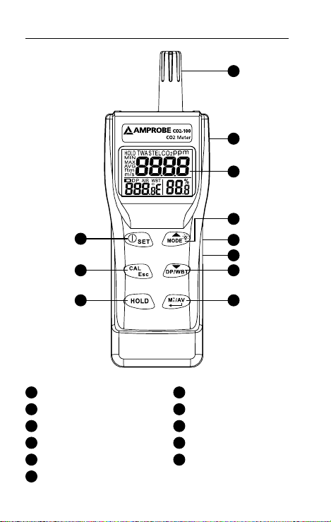
CO2-100 CO2 Meter
4
6
1
2
3
5
11
10
7
8
Humidity Sensor
1
LCD Display
3
Backlight/Roll Up Key
5
Temp. Mode/Roll Down Key
7
Min/Max/Avg./Enter Key
9
DC Adaptor Port
11
9
CO2 Sensor (Rear Side)
2
POWER/SET Key
4
Calibration/Escape Key
6
Data Hold Key
8
USB Port
10
Page 6

LCD Display
8
9
56 7
4
1
10
3
11 12
1
Primary Screen Displays CO2 Concentration
2
Relative Humidity In %
3
Air, Dew Point, Wet Bulb Temperature Display
4
Co2 Measurement Mode
5
Unit For Co2 Concentration
6
Time Weighted Average (8 Hours)
7
Short-Term Exposure Limit
(15 Minutes Weighted Average)
To Freeze Readings
8
Minimum/Maximun Readings
9
10
Low Battery Indicator
11
Dew Point Temperature
12
Wet Bulb Temperature
2
Page 7

CONTENTS
SYMBOLS ..........................................................................2
UNPACKING AND INSPECTION .......................................2
INTRODUCTION ................................................................ 3
Features ........................................................................3
OPERATION ....................................................................... 4
Auto Power Off ........................................................... 5
Setup ............................................................................ 6
Calibration Mode ........................................................ 7
USB Interface capabilities ........................................... 8
SPECIFICATION .................................................................9
MAINTENANCE AND REPAIR ........................................... 10
Battery Replacement ..................................................10
TROUBLE SHOOTING ....................................................... 11
APPENDIX ........................................................................12
1
Page 8

SYMBOLS
Caution! Refer to the explanation in this
Manual
Conforms to relevant Australian standards
Complies with European Directives
Do not dispose of this clamp meter as
unsorted municipal waste. Contact a qualified
recycler for disposal.
Warning and Precautions
• Avoid condensation on CO2 sensor
• Do not hold the meter close to faces in case
exhalation affects CO2 levels.
• Do not calibrate the meter in the air with
unknown CO2 concentration. Otherwise, it will
be calibrated as 400ppm by default and leads to
inaccurate measurements.
UNPACKING AND INSPECTION
Your shipping carton should include:
1 CO2-100 CO2 Meter
4 AA battery
1 User manual
1 Hard carrying case
If any of the items are damaged or missing, return
the complete package to the place of purchase for an
exchange.
2
Page 9

INTRODUCTION
Thank you for purchasing this portable CO2 meter. The
meter measures CO2 level, air temp., dew point, wet
bulb temp. and humidity and is an ideal instrument for
indoor air quality (IAQ) diagnosis.
Poor indoor air quality is considered unhealthy because
it causes tiredness, loss of ability to concentrate, and
even illness (ex. Sick Building Syndrome). IAQ monitoring
and survey, especially on CO2 level and air ventilation
become widely applied in public areas such as offices,
classrooms, factories, hospitals and hotels. It is also
suggested in regulations of industrial hygiene in some
countries. (Appendix)
The portable CO2 meter uses NDIR (non-dispersive
infrared) technology to ensure the reliability and long
term stability. It’s useful in verifying HVAC system
performance and air ventilation control
Features
• Triple displays of CO2 level, temp. and humidity.
• Stable NDIR sensor for CO2 detection.
• Statistics of weighted averages (TWA & STEL)
• Backlight for working in dark area
• Audile CO2 warning alarm
• Battery and adaptor power supply
• Easy manual calibration on CO2 and humidity
• USB PC connection
3
Page 10
OPERATION
1. Press “POWER/SET” to turn instrument on and off.
At power up, it emits a short beep and performs
30 seconds countdown for meter warm up, then
enters normal mode.
2. The meter starts measurement when power
on and update readings every second. In the
condition of operating environment change (ex.
from high to low temp.), it takes 30 sec to respond
for CO2 sensor and 30 minutes for RH.
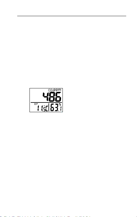
3. Press “DP/WBT” to switch temperatures
display. The lower left display will cycle from air
temperature, dew point temp., and wet bulb
temp. (Fig.1)
Fig.1
4. Press “HOLD” to freeze the readings, “HOLD”
icon is displayed on the left top of LCD. All current
readings are kept unchanged, except STEL and
TWA. Press “HOLD” again to cancel data hold
function.
5. Hold down “MODE/p”for more than 1 second to
activate and cancel backlight.
6. Press “MAX/MIN” to see the minimum, maximum,
and weighted average readings. Each press of it
displays MIN, MAX, STEL, TWA in sequence and
returns to normal mode. In MIN and MAX modes,
it shows the minimum and maximum readings
of CO2 on main display, and of AIR/DP/WBT
temperatures and humidity on the lower displays.
4
Page 11
In STEL and TWA modes, the main display shows
the weighted average of CO2 readings for the past
15 minutes (STEL) and 8 hours(TWA), but the lower
displays are the current AIR, DP/WB temperatures
and humidity readings.
NOTE:
• If the meter is turned on for shorter than 15
minutes, the STEL value will be the weighted
average of readings taken since power on. Same
for TWA values appear before 8 hours.
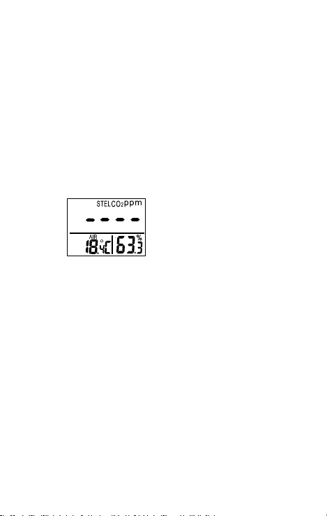
• It takes at least 5 minutes to calculate STEL and
TWA. The display shows “----” during the first 5
minutes from power on (Fig.2).
Fig.2
• While all readings are held unchanged, STEL
and TWA will keep updating every 5 minutes.
7. The instrument emits beeps (Abt.80dB) when CO2
level goes over the set limit and stops when any
key (but “POWER“ key) was pressed or readings
fall below the set value. It beeps again when value
goes over the limit. Restart the meter if beeper
can’t be stopped.
Auto Power Off
The meter turns off automatically after 20 minutes of
inactivity. To override the function, hold down “POWER
/ SET” and ”HOLD” for 2 seconds to turn on the meter
until “n” appears.
5
Page 12

Setup
The advanced setup mode lets you customize your meter.
2 types parameter are available.
P1.0: CO2 alarm threshold setting
P3.0: Temperature unit setting
P1.0 CO2 alarm threshold setting
Hold down “POWER/SET” under normal mode for more
than 1 sec to enter set up mode. To exit setup, press
“CAL/ESC” in P1.0 or P3.0.
When entering setup mode, P1.0 and “AL” are displayed
on the LCD (Fig.3). Press “ENTER” to go into P1.1 for
setting CO2 alarm threshold. The current set value will
be blinking on LCD (Fig.4). Press “p”to increase the
value or “q”to decrease. Each press tunes 100 ppm and
the alarm range is from 100 to 9900ppm. When the
preferred alarm value is set, press “ENTER” to save the
setting or “ESC” without saving and return to P1.0.
Fig.3 Fig.4
P3.0: Temperature unit setting
Press “p“or “q”in P1.0 to access P3.0 for setting up
temperature scale. Press “ENTER” and it goes into P3.1
with blinking °C or °F current set on the lower left
display. To switch °C or °F, press “p“or “q. Then press
“ENTER” to save the setting or “ESC” without saving and
return to P3.0.
6
Page 13

Calibration Mode
CO2 calibration
1. Place the meter in an outdoor area with well
ventilated air. Turn on the meter and hold down
“CAL” and “q” simultaneously to enter CO2
calibration mode. 400ppm and “CAL” are blinking
on the LCD while performing calibration (Fig.5).
Fig.5
2. Wait about 5 minutes until it stops blinking and
the calibration completes automatically and back
to normal mode.
3. To abort the calibration, turn off the meter at any
time.
Humidity calibration
1. Plug the sensor probe into 33% salt bottle. Hold
down “CAL” and “q” under normal mode to
enter 33% calibration. “CAL” and calibrating
value (32.7% if at 25°C) are blinking on the LCD
with current temperature at the left. Meter is now
calibrating, and will finish in about 60 minutes
when “CAL” and humidity value stop blinking.
2. After 33% calibration, plug the sensor probe into
75% salt bottle, then press “ENTER” to enter 75%
calibration. “CAL” and calibrating value (75.2%
if at 25°C) are blinking on the LCD with current
temperature at the left. Meter is now calibrating.
Wait about 60 minutes until blinking stops, then
calibration is completed and it returns to normal
mode.
7
Page 14

3. Users can also calibrate either point. To calibrate
33% only, press “ESC” and exit when 33%
calibration is completed. To calibrate 75%
only, press “p” or “q”within 5 minutes while
initializing 33% calibration. To abort calibration,
just turn off the meter.
USB Interface Capabilities
The USB cable and software (optional kit) are required
to transfer data to a PC. Install the USB driver in the
software first before connection.
8
Page 15

SPECIFICATION
CO2
Range
Resolution 1 ppm
Accuracy
Pressure
Dependence Pressure, 100kPa
Temperature
Range -10.0~60.0°C (14~140°F)
Resolution 0.1°C /0.1°F
Accuracy ±0.6°C / ±0.9°F
Humidity
Range 0.0~95%
Resolution 0.1%
Accuracy ±3%(10~90% at 25°C) ; ±5%(others)
Operating
environment
Storage
environment
Power supply 4pcs AA batteries
- EMC: Conforms to EN61326-1. This product complies
with requirements of the following European Community Directives:
89/ 336/ EEC (Electromagnetic Compatibility) and 73/ 23/ EEC
(Low Voltage) as amended by 93/ 68/ EEC (CE Marking). However,
electrical noise or intense electromagnetic fields in the vicinity of
the equipment may disturb the measurement circuit. Measuring
instruments will also respond to unwanted signals that may be
present within the measurement circuit. Users should exercise care
and take appropriate precautions to avoid misleading results when
making measurements in the presence of electronic interference.
0~9999ppm
(5001~9999 out of accuracy scale range)
±30ppm±5%rdg (0~5000)
(Not specified for out of scale)
+1.6% reading per kPa deviation from
normal
0~50°C, 0~95%RH (avoid condensation)
-20~60°C, 0~99%RH
(avoid condensation)
9
Page 16

MAINTENANCE AND REPAIR
If there appears to be a malfunction during the
operation of the meter, the following steps should be
performed in order to isolate the cause of the problem.
1. Check the battery. Replace the battery
immediately when the “
the LCD.
2. Review the operating instructions for possible
mistakes in operating procedure.
Except for the replacement of the battery, repair of the
meter should be performed only by a Factory Authorized
Service Center or by other qualified instrument service
personnel. The front panel and case can be cleaned with
a mild solution of detergent and water. Apply sparingly
with a soft cloth and allow to dry completely before
using. Do not use aromatic hydrocarbons or chlorinated
solvents for cleaning.
” symbol appears on
BATTERY REPLACEMENT
1. The meter is powered by either 4 AA batteries or a
DC adaptor (9V/1A output).
2. When battery voltage gets low, “
will appear on the LCD (Fig.6). And beeper sounds.
The CO2 sensor can’t work under low voltage, so it
beeps to indicate failed CO2 measurement and the
readings won’t be displayed. Please replace with
fresh batteries or connect with an adaptor.
” and “Lob”
10
Page 17

TROUBLE SHOOTING
Can’t power on
• Make sure you press power key more than 0.3
second.
• Check the battery conditions and replace if
necessary.
• Check whether the adaptor is well plugged.
• Move batteries away for one minute and then
re-install.
Display disappear
• Check whether the low battery icon is appeared
before the display is off. If yes, replace with new
batteries.
Fixed readings
• Check whether data hold function was activated.
(HOLD icon at the left top)
Slow response
• Check whether the air ow channels on the rear
were blocked
Error code
E01: CO2 sensor damaged.
E02: The value is under range.
E03: The value is over range.
E04: The original data error results in this error
(DP, WB)
E07: Too low voltage to measure CO2. Replace
batteries or use an adaptor.
E11: Retry humidity calibration.
E17: Retry CO2 calibration.
E31: Temperature sensor damaged.
E34: Humidity sensor damaged.
11
Page 18

APPENDIX - CO2 LEVELS AND GUIDELINES
NIOSH recommendations
250-350 ppm: normal outdoor ambient concentrations
600 ppm: minimal air quality complaints
600-1000 ppm: less clearly interpreted
1000 ppm: indicates inadequate ventilation; complaints
such as headaches, fatigue, and eye/throat irritation will
be more widespread. 1000 ppm should be used as an
upper limit for indoor levels.
ASHRAE Standard 62-1989: 1000ppm
CO2 concentration in occupied building should not
exceed 1000ppm.
Building bulletin 101 (BB101): 1500ppm
UK standards for schools say that CO2 at averaged over
the whole day(i.e. 9am to 3.30pm) should not exceed
1500ppm.
OSHA: 5000ppm
Time weighted average over five 8-hour work days
should not exceed 5000ppm.
Germany, Japan, Australia, UK...: 5000ppm
8 hours weighted average in occupational exposure limit
is 5000ppm.
12
Page 19

 Loading...