

Page 1

Circuit Tracer
Transmitter
BT-120, BT-250
Breaker Tracer
Circuit Tracer
Receiver
User Manual
ENG FRE
SPA
Page 2

Page 3

BT-120
BT-250
Breaker Tracer
User Manual
8/2018, 6011458B
©2018 Amprobe
All rights reserved. Printed in China
English
Page 4

Limited Warranty and Limitation of Liability
Your Amprobe product will be free from defects in material and workmanship for one year from
the date of purchase unless local laws require otherwise. This warranty does not cover fuses,
disposable batteries or damage from accident, neglect, misuse, alteration, contamination, or
abnormal conditions of operation or handling. Resellers are not authorized to extend any other
warranty on the behalf of Amprobe. To obtain service during the warranty period, return the
product with proof of purchase to an authorized Amprobe Service Center or to an Amprobe
dealer or distributor. See Repair Section for details. THIS WARRANTY IS YOUR ONLY REMEDY.
ALL OTHER WARRANTIES - WHETHER EXPRESS, IMPLIED OR STATUTORY - INCLUDING IMPLIED
WARRANTIES OF FITNESS FOR A PARTICULAR PURPOSE OR MERCHANTABILITY, ARE HEREBY
DISCLAIMED. MANUFACTURER SHALL NOT BE LIABLE FOR ANY SPECIAL, INDIRECT, INCIDENTAL
OR CONSEQUENTIAL DAMAGES OR LOSSES, ARISING FROM ANY CAUSE OR THEORY. Since some
states or countries do not allow the exclusion or limitation of an implied warranty or of incidental
or consequential damages, this limitation of liability may not apply to you.
Repair
All Amprobe returned for warranty or non-warranty repair or for calibration should be
accompanied by the following: your name, company’s name, address, telephone number, and
proof of purchase. Additionally, please include a brief description of the problem or the service
requested and include the test leads with the meter. Non-warranty repair or replacement charges
should be remitted in the form of a check, a money order, credit card with expiration date, or a
purchase order made payable to Amprobe.
In-warranty Repairs and Replacement – All Countries
Please read the warranty statement and check your battery before requesting repair. During
the warranty period, any defective test tool can be returned to your Amprobe distributor for an
exchange for the same or like product. Please check the “Where to Buy” section on amprobe.com
for a list of distributors near you. Additionally, in the United States and Canada, in-warranty repair
and replacement units can also be sent to an Amprobe Service Center (see address below).
Non-warranty Repairs and Replacement – United States and Canada
Non-warranty repairs in the United States and Canada should be sent to an Amprobe Service
Center. Call Amprobe or inquire at your point of purchase for current repair and replacement rates.
USA: Canada:
Amprobe Amprobe
Everett, WA 98203 Mississauga, ON L4Z 1X9
Tel: 877-AMPROBE (267-7623) Tel: 905-890-7600
Non-warranty Repairs and Replacement – Europe
European non-warranty units can be replaced by your Beha-Amprobe distributor for a nominal charge.
Please check the “Where to Buy” section on beha-amprobe.com for a list of distributors near you.
Beha-Amprobe
Division and reg. trademark of Fluke Corp. (USA)
Germany* United Kingdom The Netherlands - Headquarters**
In den Engematten 14 52 Hurricane Way Science Park Eindhoven 5110
79286 Glottertal Norwich, Norfolk 5692 EC Son
Germany NR6 6JB United Kingdom The Netherlands
Phone: +49 (0) 7684 8009 - 0 Phone: +44 (0) 1603 25 6662 Phone: +31 (0) 40 267 51 00
beha-amprobe.de beha-amprobe.com beha-amprobe.com
*(Correspondence only – no repair or replacement available from this address. European
customers please contact your distributor.)
**single contact address in EEA Fluke Europe BV
Page 5

BT-120 BT-250 Breaker Tracer
1
6
2
Circuit Tracer
Receiver
7
Circuit Tracer
Transmitter
4
3
Sensor Location
1
Identification Arrow LED Indicator
2
Battery Compartment
3
ON/OFF Switch
4
Adaptor Prongs
5
Transmitter Power LED Indicator
6
7
Receiver Power LED Indicator
5
Page 6

BT-120 BT-250 Breaker Tracer
CONTENTS
SYMBOLS AND WARNINGS ..................................................................................2
Safety Information ...........................................................................................2
Warnings and Precautions ................................................................................3
UNPACKING AND INSPECTION .............................................................................3
INTRODUCTION .....................................................................................................4
OPERATION ...........................................................................................................4
SPECIFICATION ......................................................................................................5
BATTERY REPLACEMENT .......................................................................................7
MAINTENANCE AND REPAIR ................................................................................7
1
Page 7

SYMBOLS
Battery
Double Insulated
Alternating Current
Direct Current
Application around and
removal from hazardous
live conductors is permitted
Do not dispose of this
product as unsorted
municipal waste. Contact
=
a qualified recycler for
disposal.
Underwriters Laboratories.
[Note: Canadian and US.]
Caution ! Refer to the
Manual
Dangerous Voltage
Earth Ground
Fuse
Complies with European
�
Directives
Conforms to relevant
Australian standards
Audible tone
Safety Information
• The BT-120 Breakers Tester is conformed to UL 61010-1; CAT II 120 V, class
II and pollution degree 1 or 2.
• The BT-250 Breakers Tester is conformed to UL 61010-1; CAT II 250 V, class
II and pollution degree 1 or 2.
Warning and precaution
• Before and after hazardous voltage measurements, test the voltage
function on a known source such as line voltage to determine proper
meter functioning.
• Do not touch the membrance.
• Inspect the receiver and the transmitter before every use. Do not use any
damaged part.
• Never ground yourself when taking measurements. Do not touch
exposed circuit elements or test probe tips.
• Do not operate the instrument in an explosive atmosphere.
2
Page 8

• To reduce the risk of fire or electric shock, do not expose this product to
rain or moisture.
• The meter is intended only for indoor use. To avoid electrical shock
hazard, observe the proper safety precautions when working with
voltages above 60 VDC, 42.4 Vpk, or 30 VAC rms. These voltage levels
pose a potential shock hazard to the user.
UNPACKING AND INSPECTION
Your shipping carton should include:
1 Receiver
1 Transmitter
1 9V alkaline battery
1 User manual
1 Carrying case (BT-250)
1 Connection cable (BT-250)
1 Light fixture adapter (BT-250)
If any of the items are damaged or missing, return the complete package to
the place of purchase for an exchange.
INTRODUCTION
The Amprobe BT Series Breaker Tracers work on powered systems from 90 to
120 V AC (BT-120) and 90 to 250 V AC (BT-250) and are designed for use in
residential and light commercial environments. Both kits comes complete with
a Transmitter and Receiver.
Features:
• Identifies circuit breaker location
• Works on all electrical systems within the voltage rating range
• Perfect for office, residential and HVAC applications
• Automatic sensitivity adjustment
• Microprocessor controlled
• Extremely accurate reading always finds the right breaker
• Durable and dependable
3
Page 9

OPERATION
Breaker and Fuse Identification
1. Plug the Transmitter into an energized wall outlet (Figure 1).
Transmitter
Circuit Tracer
Figure 1
2. Make sure the red LED is ON to indicate that the outlet is energized.
3. Push the Power switch on the Receiver to turn it ON. The Receiver will
beep and the Power LED will be lit.
4. At the breaker panel or fuse box, hold the Receiver perpendicular to the
breakers. Scan slowly all breakers once to calibrate the Receiver. During
this scan, the Receiver may beep and flash at several breakers. This is a
normal part of the identification process (Figure 2).
Receiver
Circuit Tracer
Figure 2
5. Without touching the ON/OFF button, begin scanning again to identify
the right breaker or fuse. When the Receiver beeps, the correct breaker
has been identified.
6. Push and hold the Power switch for three seconds to turn the Receiver
off. Beeping and flashing during the shutdown is normal.
7. Unplug the Transmitter from the wall outlet.
4
Page 10
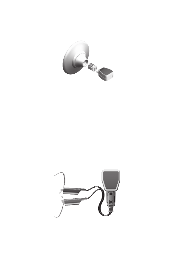
Using the BT-LFA Incandescent Light Fixture Adapter (BT-250 only)
1. Remove the light bulb exercising the proper caution.
2. Screw in the BT-LFA adapter.
3. Plug the Transmitter into the BT-LFA (Figure 3).
Figure 3
4. Preform scan following directions in step 4 under “Operation.”
Using the BT-VLA High Voltage Leads Adapter (BT-250 only)
The BT-250 Transmitter can be used alone on 110V circuits. For circuits up to
250V or exposed circuits, use the BT-VLA and follow the directions listed below.
1. Plug Transmitter into high voltage lead receptacle. Be sure that the
Transmitter is completely seated and that no part of the Transmitter
prongs are exposed.
2. Attach the high voltage leads to the terminal or conductor while
exercising extreme caution (Figure 4).
3. Preform scan following directions in step 4 under “Operation.”
Figure 4
5
Page 11

SPECIFICATIONS
Operating & Detection BT-120 BT-250
Voltage for Transmitter
Operating Frequency 50 Hz to 60 Hz 40 Hz to 70 Hz
Storage Temperature 32 °F to 104 °F (0 °C to 40 °C)
Operating Temperature 32 °F to 104 °F (0 °C to 40 °C)
Sensitivity Adjustment Automatic
Power Supply 9 V alkaline battery (Receiver)
Transmitter Polarity Automatic
Humidity 50% RH (non condensing)
Environmental
Conditions
Caution
90-120 VAC,
Not to exceed ±10%
(inclusive in rating)
Indoor use, altitudes up to 2000 m,
Pollution Degree 1 or 2, Installation Category II
BT-VLA cord assembly to be used with Transmitter
only according to instructions.
90-250 VAC,
Not to exceed ±10%
(inclusive in rating)
BATTERY REPLACEMENT
Power is supplied by one 9 V alkaline battery (Receiver).
The Identification Arrow LED on the Receiver will not turn ON when
replacement is needed. To replace the battery, remove the screw from the back
of the meter and slide the battery door outward. Remove the battery from
case bottom and replace it with a fresh 9 V alkaline battery.
Slide battery
door outward
Remove screw
6
Page 12

MAINTENANCE AND REPAIR
If there appears to be a malfunction during the operation of the tracer, the
following steps should be performed in order to isolate the cause of the
problem.
1. Check the battery. Replace the battery immediately if the Receiver LED
doesn’t turn ON.
2. Review the operating instructions for possible mistakes in operating
procedure.
Except for the replacement of the battery, repair of the tracer should be
performed only by a Factory Authorized Service Center or by other qualified
instrument service personnel.
The front panel and case can be cleaned with a mild solution of detergent and
water. Apply sparingly with a soft cloth and allow to dry completely before
using. Do not use aromatic hydrocarbons or chlorinated solvents for cleaning.
7
Page 13

Page 14

Page 15

BT-120
BT-250
Traceur de disjoncteurs
Manuel de l’utilisateur
8/2018, 6011458B
©2018 Amprobe
Tous droits réservés. Imprimé en Chine
Français
Page 16

Garantie limitée et limitation de responsabilité
Votre produit Amprobe sera exempt de défauts de matériaux et de fabrication pendant
un (1) an à compter de la date d'achat, sauf exigence contraire en vertu de la juridiction
locale. Cette garantie ne s'applique pas aux fusibles, aux piles jetables ou endommagées
par accident, à la négligence, à la mauvaise utilisation, à l'altération, à la contamination
ou aux conditions anormales d'utilisation ou de manipulation. Les revendeurs ne sont pas
autorisés à prolonger toute autre garantie au nom de Amprobe. Pour une réparation au
cours de la période de garantie, retournez le produit avec la preuve d'achat à un centre
de service autorisé par Amprobe ou à un revendeur ou un distributeur Amprobe. Voir
la section Réparation pour plus de détails. CETTE GARANTIE EST VOTRE SEUL RECOURS.
TOUTES LES AUTRES GARANTIES – QU'ELLES SOIENT EXPLICITES, IMPLICITES OU JURIDIQUES
– Y COMPRIS LES GARANTIES IMPLICITES D'ADAPTATION À UN USAGE PARTICULIER OU
MARCHAND, SONT EXCLUES. LE FABRICANT NE SERA PAS RESPONSABLE DES DOMMAGES
SPECIAUX, INDIRECTS, ACCESSOIRES OU CONSECUTIFS PROVENANT DE TOUTE CAUSE
OU THEORIE. Etant donné que certains pays ou états n'autorisent pas l'exclusion ou la
limitation des garanties implicites ou des dommages directs ou indirects, cette limitation de
responsabilité peut ne pas s'appliquer à vous.
Réparation
Tous les produits Amprobe retournés pour réparation sous garantie ou hors garantie ou
pour étalonnage doivent être accompagnés de ce qui suit: votre nom, le nom de votre
société, votre adresse, votre numéro de téléphone et la preuve d'achat. De plus, veuillez
inclure une brève description du problème ou du service demandé et incluez les cordons de
mesure avec le compteur. Les frais de réparation ou de remplacement non garantis doivent
être réglés sous forme de chèque, mandat, carte de crédit avec date d'expiration ou bon de
commande payable à Amprobe.
Réparations et remplacement couverts par la garantie – Tous les pays
Veuillez lire la déclaration de garantie et vérifier la pile avant de demander une réparation.
Pendant la période de garantie, tout outil de vérification défectueux peut être retourné
à votre distributeur Amprobe pour un échange de produit identique ou similaire. Veuillez
consulter la section «Où acheter » sur le site amprobe.com pour obtenir une liste des
distributeurs près de chez vous. En outre, aux États-Unis et au Canada, les réparations sous
garantie et les unités de remplacement peuvent également être envoyés à un centre de
service Amprobe (voir adresse ci-dessous).
Réparation et remplacement non couverts par la garantie – États-Unis et Canada
Pour les réparations non couvertes par la garantie aux États-Unis et au Canada, l'appareil
doit être envoyé à un centre de service Amprobe. Appelez Amprobe ou renseignez-vous
auprès de votre point de vente pour les tarifs de réparation et de remplacement actuels.
États-Unis: Canada:
Amprobe Amprobe
Everett, WA 98203 Mississauga, ON L4Z 1X9
Tél: 877-AMPROBE (267-7623) Tél.: 905-890-7600
Réparation et remplacement non couverts par la garantie – Europe
Les unités hors garantie européenne peuvent être remplacées par votre distributeur Amprobe/
Beha-Amprobe pour une somme modique. Veuillez consulter la section «Où acheter» sur le site
beha-amprobe.com pour obtenir une liste des distributeurs près de chez vous.
Beha-Amprobe
Division et marque déposée de Fluke Corp. (USA)
Allemagne* Royaume-Uni Pays-Bas - Siège social**
In den Engematten 14 52 Hurricane Way Science Park Eindhoven 5110
79286 Glottertal Norwich, Norfolk 5692 EC Son
Allemagne NR6 6JB Royaume-Uni Pays-Bas
Téléphone : +49 (0) 7684 8009 - 0 Téléphone: +44 (0) 1603 25 6662 Téléphone: +31 (0) 40 267 51 00
beha-amprobe.de beha-amprobe.com beha-amprobe.com
*(Correspondance uniquement: aucune réparation ou remplacement à cette adresse.
Clients européens, veuillez contacter votre distributeur.)
**adresse de contact unique dans l'EEE Fluke Europe BV
Page 17

Traceur de disjoncteurs BT-120 BT-250
1
6
2
Circuit Tracer
Receiver
7
Circuit Tracer
Transmitter
4
5
3
Localisation du capteur
1
Indicateur LED flèche d'identification
2
Compartiment des piles
3
Interrupteur MARCHE/ARRÊT
4
Broches d'adaptateur
5
Indicateur LED alimentation transmetteur
6
7
Indicateur LED alimentation récepteur
Page 18

Traceur de disjoncteurs BT-120 BT-250
TABLE DES MATIÈRES
SYMBOLES ET AVERTISSEMENTS .........................................................................2
Informations de sécurité ...................................................................................2
Avertissements et précautions .........................................................................3
DÉBALLAGE ET INSPECTION .................................................................................3
INTRODUCTION .....................................................................................................4
FONCTIONNEMENT ..............................................................................................4
SPÉCIFICATIONS ....................................................................................................5
REMPLACEMENT DE LA PILE .................................................................................7
ENTRETIEN ET RÉPARATIONS ................................................................................7
1
Page 19

SYMBOLES
Pile
Double isolation
Courant alternatif
Courant continu
L'application à proximité
et le retrait de conducteurs
sous tension dangereux
sont autorisés.
Ne jetez pas ce produit
avec les déchets municipaux
non triés. Contactez un
=
recycleur qualifié pour la
mise au rebut.
Underwriters Laboratories.
[Remarque : Canada et
États-Unis.]
Attention ! Consultez le
manuel
Tension dangereuse
Prise de terre
Fusible
Conforme aux directives
�
européennes.
Conforme aux normes
australiennes pertinentes.
Son audible
Informations de sécurité
• Le testeur de disjoncteurs BT-120 est conforme à UL 61010-1; CAT II 120 V,
classe II et degré de pollution 1 ou 2.
• Le testeur de disjoncteurs BT-250 est conforme à UL 61010-1; CAT II 250 V,
classe II et degré de pollution 1 ou 2.
Avertissement et précautions
• Avant et après des mesures de tension dangereuses, testez la fonction
de tension sur une source connue telle qu'une tension de ligne pour
déterminer le bon fonctionnement de l'appareil.
• Ne touchez pas la membrane.
• Inspectez le récepteur et le transmetteur avant chaque utilisation.
N'utilisez pas de pièces endommagées.
• Ne vous raccordez jamais à la terre en prenant des mesures. Ne touchez
pas les éléments exposés du circuit ou les pointes des sondes de test.
• N'utilisez pas l'instrument dans une atmosphère explosive.
2
Page 20

• Pour réduire le risque d'incendie ou de décharge électrique, n'exposez
pas ce produit à la pluie ou à l'humidité.
• L'appareil est uniquement destiné à une utilisation à l'intérieur.
Pour éviter tout risque de décharge électrique, respectez les mesures
de sécurité appropriées lorsque vous travaillez avec des tensions
supérieures à 60 V CC, 42,4 V crête ou 30 V CA RMS. Ces niveaux de
tension présentent un risque potentiel de décharge électrique pour
l'utilisateur.
DÉBALLAGE ET INSPECTION
Votre emballage doit contenir:
1 Récepteur
1 Transmetteur
1 pile alcaline 9V
1 Manuel de l'utilisateur
1 Mallette de transport (BT-250)
1 Câble de raccordement (BT-250)
1 Adaptateur pour luminaire (BT-250)
Si l'un de ces éléments est manquant ou endommagé, retournez l'emballage
complet à votre point d'achat pour un échange.
INTRODUCTION
Les traceurs de disjoncteurs Amprobe série BT fonctionnent sur des systèmes
sous tension de 90 à 120 V CA (BT-120) et de 90 à 250 V CA (BT-250) et
sont conçus pour une utilisation dans des environnements résidentiels et
commerciaux lumineux. Les deux kits comprennent un transmetteur et un
récepteur.
Caractéristiques:
• Identifie l'emplacement des disjoncteurs
• Fonctionne sur tous les systèmes électriques dans la plage de tension
nominale
• Idéal pour les applications professionnelles, résidentielles et CVC
• Réglage automatique de la sensibilité
• Contrôlé par microprocesseur
• La mesure extrêmement précise trouve toujours le bon disjoncteur
• Durable et fiable
3
Page 21

FONCTIONNEMENT
Identification des disjoncteurs et des fusibles
1. Branchez le transmetteur sur une prise murale alimentée (Figure 1).
Transmitter
Circuit Tracer
2. Assurez-vous que la LED rouge est allumée pour indiquer que la prise est
Figure 1
alimentée.
3. Appuyez sur l'interrupteur d'alimentation du récepteur pour l'allumer.
Le récepteur émet un bip et la LED d'alimentation s'allume.
4. Au niveau du panneau des disjoncteurs ou du boîtier de fusibles, tenez
le récepteur perpendiculairement aux disjoncteurs. Balayez lentement
tous les disjoncteurs une fois pour étalonner le récepteur. Pendant ce
balayage, le récepteur peut émettre un bip et clignoter avec plusieurs
disjoncteurs. Il s'agit d'une partie normale du processus d'identification
(Figure 2).
Receiver
Circuit Tracer
Figure 2
5. Sans toucher le bouton MARCHE/ARRÊT, commencez à balayer à
nouveau pour identifier le bon disjoncteur ou le bon fusible. Lorsque le
récepteur émet un bip, le bon disjoncteur a été identifié.
6. Appuyez et maintenez le bouton d'alimentation enfoncé pendant
trois secondes pour éteindre le récepteur. Les bips et les clignotements
pendant l'arrêt sont normaux.
7. Débranchez le transmetteur de la prise murale.
4
Page 22

Utilisation de l'adaptateur pour luminaire à incandescence BT-LFA (BT-250
uniquement)
1. Retirez l'ampoule en faisant preuve de prudence.
2. Vissez l'adaptateur BT-LFA.
3. Branchez le transmetteur sur le BT-LFA (Figure 3).
Figure 3
4. Effectuez le balayage en suivant les instructions de l'étape 4 dans
«Fonctionnement».
Utilisation de l'adaptateur pour fils haute tension BT-VLA (BT-250 uniquement)
Le transmetteur BT-250 peut être utilisé seul sur des circuits 110V. Pour les
circuits jusqu'à 250V ou les circuits exposés, utilisez le BT-VLA et suivez les
instructions indiquées ci-dessous.
1. Branchez le transmetteur sur une prise à fils haute tension. Assurez-vous
que le transmetteur est complètement inséré et qu'aucune partie des
broches du transmetteur n'est exposée.
2. Raccordez les fils haute tension à la borne ou au conducteur en faisant
preuve d'une prudence extrême (Figure 4).
3. Effectuez le balayage en suivant les instructions de l'étape 4 dans
«Fonctionnement».
Figure 4
5
Page 23

SPÉCIFICATIONS
Fonctionnement et
détection
Tension pour le
transmetteur
Fréquence de
fonctionnement
Température de
stockage
Température de
fonctionnement
Réglage de la
sensibilité
90-120V CA,
Ne doit pas dépasser ±10%
(inclus dans calibre)
50 Hz à 60 Hz 40 Hz à 70 Hz
32 °F à 104 °F (0 °C à 40 °C)
32 °F à 104 °F (0 °C à 40 °C)
Automatique
Alimentation Pile alcaline 9 V (Récepteur)
Polarité du
transmetteur
Automatique
Humidité 50% HR (sans condensation)
Conditions
environnementales
Attention!
Utilisation à l'intérieur, altitudes jusqu'à 2000 m,
Degré de pollution 1 ou 2, Catégorie d'installation II
Ensemble cordon BT-VLA à utiliser avec le transmetteur
conformément aux instructions uniquement.
BT-120 BT-250
90-250V CA,
Ne doit pas dépasser ±10%
(inclus dans calibre)
REMPLACEMENT DE LA PILE
L'alimentation est fournie par une pile alcaline 9 V (Récepteur).
La LED flèche d'identification du récepteur ne s'allume pas si un remplacement
est nécessaire. Pour remplacer la pile, enlevez la vis de l'arrière de l'appareil et
faites coulisser la trappe du compartiment de la pile vers l'extérieur. Enlevez la
pile du fond du boîtier et remplacez-la par une pile alcaline 9 V neuve.
Faire coulisser le couvercle du compartiment
des piles vers l'extérieur
Enlever la vis
6
Page 24

ENTRETIEN ET RÉPARATION
Si un dysfonctionnement survient pendant l'utilisation du traceur, les étapes
suivantes doivent être effectuées afin d'isoler la cause du problème.
1. Vérifiez la pile. Remplacez immédiatement la pile si la LED du récepteur
ne s'allume pas.
2. Vérifiez les instructions d'utilisation pour de possibles erreurs dans la
procédure d'exploitation.
Sauf pour le remplacement de la pile, la réparation du traceur doit
uniquement être effectuée par un centre de service autorisé par l'usine ou par
tout autre personnel qualifié de réparation d'instruments.
La face avant et la mallette peuvent être nettoyées avec un détergent doux et
de l'eau. Appliquer en petite quantité avec un chiffon doux et laisser sécher
complètement avant utilisation. Ne pas utiliser d'hydrocarbures aromatiques
ou de solvants chlorés pour le nettoyage.
7
Page 25

Page 26

Page 27

BT-120
BT-250
Rastreador de disyuntores
Manual de usuario
8/2018, 6011458B
©2018 Amprobe
Todos los derechos reservados. Impreso en China
Español
Page 28

Garantía limitada y limitación de responsabilidad
Su producto Amprobe no presentará defectos materiales ni de mano de obra durante
un año a partir de la fecha de compra, a menos que las leyes locales se pronuncien en
otro sentido. Esta garantía no cubre fusibles, pilas desechables o daños provocados por
accidentes, negligencia, mal uso, alteración, contaminación o condiciones anómalas de
funcionamiento o manipulación. Los revendedores no tienen autorización para ampliar
ninguna otra garantía en nombre de Amprobe. Para obtener servicio durante el período de
garantía, devuelva el producto con una prueba de compra a un Centro de servicio técnico
autorizado de Amprobe o a un proveedor o distribuidor de Amprobe. Consulte la sección
Reparaciones para obtener más detalles. ESTA GARANTÍA SERÁ SU ÚNICO MEDIO DE
COMPENSACIÓN. POR EL PRESENTE DOCUMENTO, SE RECHAZAN EL RESTO DE GARANTÍAS
(YA SEAN EXPRESAS, IMPLÍCITAS O LEGALES), INCLUIDAS LAS GARANTÍAS IMPLÍCITAS,
DE ADECUACIÓN PARA UNA FINALIDAD DETERMINADA O DE COMERCIALIZACIÓN. EL
FABRICANTE NO ASUMIRÁ NINGUNA RESPONSABILIDAD POR NINGÚN DAÑO O PÉRDIDA
ESPECIAL, INDIRECTA, INCIDENTAL O CONSECUENTE, QUE SE HAYA PROVOCADO POR
CUALQUIER CAUSA O TEORÍA. Dado que algunos estados o países no permiten la exclusión
o limitación de una garantía implícita o de daños incidentales o consecuentes, es posible
que esta limitación no se le aplique a usted.
Reparación
Todas las herramientas de Amprobe devueltas para realizar una reparación cubierta o
no por la garantía, o para realizar tareas de calibración, deben estar acompañadas de lo
siguiente: su nombre, nombre de la compañía, dirección, número de teléfono y justificante
de compra. Además, incluya una breve descripción del problema o del servicio solicitado,
así como los conductores de comprobación con el medidor. El pago de la reparación o
sustitución no cubierta por la garantía se hará a través de un cheque, giro postal, tarjeta de
crédito con fecha de caducidad o una orden de compra pagadera a Amprobe.
Reparaciones y reemplazos en garantía (todos los países)
Lea la declaración de garantía y compruebe las pilas antes de solicitar el servicio de
reparación. Durante el período de garantía, puede devolver cualquier herramienta de
comprobación defectuosa al distribuidor de Amprobe para que se la cambien por otra
nueva o similar. Consulte la sección "Where to Buy" (Lugares de compra) en amprobe.com
para obtener una lista de los distribuidores cercanos. Además, en Estados Unidos y Canadá,
las unidades de reparación y sustitución cubiertas por la garantía también se pueden enviar
al Centro de servicio técnico de Amprobe (consulte la dirección a continuación).
Reparaciones y sustituciones no cubiertas por la garantía: Estados Unidos y Canadá
Las reparaciones no cubiertas por la garantía en Estados Unidos y Canadá se deben enviar a
un Centro servicio técnico de Amprobe. Llame a Amprobe o pregunte en su punto de compra
las tarifas actuales de reparación y sustitución.
EE.UU.: Canadá:
Amprobe Amprobe
Everett, WA 98203 Mississauga, ON L4Z 1X9
Teléfono: 877-AMPROBE (267-7623) Tel: 905-890-7600
Reparaciones y sustituciones no cubiertas por la garantía – Europa
Su distribuidor de Beha-Amprobe debe reemplazar las unidades europeas no cubiertas por la
garantía por una cuota nominal. Consulte la sección “Dónde comprar” en el sitio web behaamprobe.com para obtener una lista de distribuidores cercanos.
Beha-Amprobe
División y marca registrada de Fluke Corp. (EE. UU.)
Alemania* Reino Unido Países Bajos - Sede central**
In den Engematten 14 52 Hurricane Way Science Park Eindhoven 5110
79286 Glottertal Norwich, Norfolk 5692 EC Son
Alemania NR6 6JB Reino Unido Países Bajos
Teléfono: +49 (0) 7684 8009 - 0 Teléfono: +44 (0) 1603 25 6662 Teléfono: +31 (0) 40 267 51 00
beha-amprobe.de beha-amprobe.com beha-amprobe.com
*(Solo correspondencia; en esta dirección no se permiten reparaciones o sustituciones.
En el caso de países europeos, se deben poner en contacto con el distribuidor).
**Única dirección de contacto en EEA Fluke Europe BV
Page 29

Rastreador de disyuntores BT-120 BT-250
1
6
2
Circuit Tracer
Receiver
7
Circuit Tracer
Transmitter
4
5
3
Ubicación del sensor
1
Indicador LED de flecha de identificación
2
Compartimiento de la pila
3
Interruptor de encendido/apagado
4
Clavijas del adaptador
5
Indicador LED de potencia del transmisor
6
7
Indicador LED de potencia del receptor
Page 30

Rastreador de disyuntores BT-120 BT-250
CONTENIDO
SÍMBOLOS Y ADVERTENCIAS ...............................................................................2
Información de seguridad ...............................................................................2
Advertencias y precauciones ............................................................................3
DESEMBALAJE Y REVISIÓN ...................................................................................3
INTRODUCCIÓN .....................................................................................................4
FUNCIONAMIENTO ...............................................................................................4
ESPECIFICACIONES ...............................................................................................5
REEMPLAZO DE LA PILA .......................................................................................7
MANTENIMIENTO Y REPARACIÓN .......................................................................7
1
Page 31

SÍMBOLOS
Pila
Aislamiento doble
Corriente alterna
Corriente continua
Aplicación y extracción
de conductores vivos
peligrosos permitidas
No deseche este producto
como un residuo
municipal sin clasificación.
=
Comuníquese con un
encargado de reciclaje
calificado para el desecho.
Underwriters Laboratories.
[Nota: Canadá y EE. UU.]
¡Precaución! Consulte el
manual
Tensión peligrosa
Masa (tierra)
Fusible
Cumplimiento con las
�
directivas europeas
Cumplimiento con los
estándares australianos
pertinentes
Tono sonoro
Información de seguridad
• El rastreador de disyuntores BT-120 cumple con UL 61010-1; CAT II 120 V,
clase II y grado de contaminación 1 o 2.
• El rastreador de disyuntores BT-250 cumple con UL 61010-1; CAT II 250 V,
clase II y grado de contaminación 1 o 2.
Advertencia y precaución
• Antes y después de las mediciones de tensiones peligrosas, pruebe la
función de tensión en una fuente conocida, como la tensión de la línea,
para determinar si el medidor funciona de forma correcta.
• No toque la membrana.
• Inspeccione el receptor y el transmisor antes de cada uso. No toque
ninguna pieza dañada.
• Nunca se ponga usted mismo a tierra al realizar mediciones. No toque
los elementos expuestos de los circuitos ni las puntas de las sondas de
prueba.
• No utilice el producto en una atmósfera explosiva.
• Para reducir el riesgo de incendios o descargas eléctricas, no exponga
este producto a la lluvia o humedad.
2
Page 32

• El medidor está diseñado únicamente para el uso en interiores.
Para evitar peligros provocados por descargas eléctricas, respete
las precauciones de seguridad adecuadas al trabajar con tensiones
superiores a 60 V de CC, 42,4 V (pico) o 30 V de CA (RMS). Estos niveles
de tensión representan un potencial peligro de descargas para el
usuario.
DESEMBALAJE E INSPECCIÓN
La caja de embalaje debe contener los siguientes artículos:
1 Receptor
1 Transmisor
1 Pila alcalina de 9 V
1 Manual de usuario
1 Estuche de transporte (BT-250)
1 Cable de conexión (BT-250)
1 Adaptador para accesorio de iluminación (BT-250)
Si alguno de estos elementos está dañado o no se encuentra presente,
devuelva la caja de embalaje completa al lugar de compra para obtener un
cambio.
INTRODUCCIÓN
Los rastreadores de disyuntores serie BT de Amprobe funcionan con sistemas
eléctricos de 90 a 120 V de CA (modelo BT-120) y de 90 a 250 V de CA (modelo
BT-250), y están diseñados para el uso en entornos residenciales y comercios
pequeños. Ambos kits incluyen un transmisor y receptor.
Características:
• Identifica la ubicación del disyuntor
• Funciona con todos los sistemas eléctricos dentro del rango de
clasificación de tensión
• Ideal para aplicaciones de oficina, hogares y HVAC (calefacción,
ventilación y aire acondicionado)
• Ajuste automático de la sensibilidad
• Control a través de microprocesador
• Lecturas extremadamente precisas que permiten encontrar siempre al
disyuntor correcto
• Resistente y confiable
3
Page 33

FUNCIONAMIENTO
Identificación de disyuntores y fusibles
1. Enchufe el transmisor a un tomacorriente energizado (fig. 1).
Transmitter
Circuit Tracer
2. Asegúrese de que el indicador LED rojo esté encendido para indicar que
el tomacorriente está energizado.
3. Presione el interruptor de encendido/apagado del receptor para
encenderlo. El receptor emitirá un pitido y se encenderá el indicador
LED de encendido.
4. En el panel de disyuntores o en la caja de fusibles, sujete el receptor
perpendicular a los disyuntores. Escanee lentamente todos los
disyuntores una vez para calibrar el receptor. Durante este escaneo, el
receptor podría emitir un pitido y parpadear en varios disyuntores. Esto
es un parte normal del proceso de identificación (fig. 2).
Figura 1
Receiver
Circuit Tracer
Figura 2
5. Sin tocar el botón de encendido/apagado, comience el escaneo
nuevamente para identificar el disyuntor o fusible correctos. Cuando
el receptor emita un pitido, esto indica que se identificó el disyuntor
correcto.
6. Mantenga presionado el interruptor de encendido/apagado durante 3
segundos para apagar el receptor. Los pitidos y parpadeos durante el
apagado son normales.
7. Desenchufe el transmisor del tomacorriente.
4
Page 34

Uso del adaptador para accesorio de iluminación BT-LFA (solo para el modelo
BT-250)
1. Extraiga la bombilla de luz con extremo cuidado.
2. Enrosque el adaptador BT-LFA.
3. Enchufe el transmisor al adaptador BT-LFA (fig. 3).
Figura 3
4. Realice el escaneo siguiendo las instrucciones detallada en el paso 4 de
la sección "Funcionamiento".
Utilización del adaptador para conductores de alta tensión (solo para el
modelo BT-250)
El transmisor BT-250 puede utilizarse sin adaptadores en circuitos de 110 V. En
el caso de circuitos de hasta 250 V o circuitos expuestos, utilice el adaptador
BT-VLA y siga las instrucciones detalladas a continuación.
1. Enchufe el transmisor a una toma con conductor de alta tensión.
Asegúrese de que el transmisor esté insertado por completo y que no
estén expuestas ningunas de las clavijas del transmisor.
2. Conecte los conductores de alta tensión al terminal o conductor
teniendo sumo cuidado (fig. 4).
3. Realice el escaneo siguiendo las instrucciones detallada en el paso 4 de
la sección "Funcionamiento".
Figura 4
5
Page 35

ESPECIFICACIONES
Funcionamiento y
detección
Tensión para el
transmisor
Frecuencia de
funcionamiento
Temperatura de
almacenamiento
Temperatura de
funcionamiento
Ajuste de sensibilidad Automático
Fuente de alimentación Pila alcalina de 9 V (receptor)
Polaridad de transmisor Automática
Humedad 50 % (humedad relativa) (sin condensación)
Condiciones
ambientales
Precaución
BT-120 BT-250
90 -120 V de CA,
Sin exceder ±10 %
(incluido en la
clasificación)
De 50 Hz a 60 Hz De 40 Hz a 70 Hz
De 32 °F a 104 °F (de 0 °C a 40 °C)
De 32 °F a 104 °F (de 0 °C a 40 °C)
Uso en interiores, altitudes de hasta 2000 m,
Grado de contaminación 1 o 2, categoría de
instalación II
El conjunto del cable del adaptador BT-VLA solo
debe utilizarse con el transmisor de acuerdo con
las instrucciones.
90 -250 V de CA,
Sin exceder ±10 %
(incluido en la
clasificación)
REEMPLAZO DE LA PILA
La alimentación se suministra a través de una pila alcalina de 9 V (receptor).
El indicador LED de flecha de identificación del receptor no se encenderá para
indicar que es necesario reemplazar la pila. Para reemplazar la pila, extraiga el
tornillo ubicado en la parte posterior del medidor y deslice el compartimiento
de la pila hacia fuera. Extraiga la pila de la parte inferior de la cubierta y
reemplácela por una pila alcalina nueva de 9 V.
Deslice la tapa de las
pilas hacia fuera
Extraiga el tornillo
6
Page 36

MANTENIMIENTO Y REPARACIÓN
Si parece que existe una falla durante el uso del rastreador, se deberán seguir
los siguientes pasos para aislar la causa del problema.
1. Inspeccione la pila. Reemplace de inmediato la pila si el indicador LED
del receptor no se enciende.
2. Examine las instrucciones de funcionamiento por posibles errores en el
procedimiento de utilización.
Excepto para el reemplazo de las pilas, las reparaciones del rastreador deberán
ser realizadas sólo por el Centro de Servicio Técnico autorizado de fábrica o
por cualquier otro personal de servicio técnico calificado.
El panel frontal y la cubierta pueden limpiarse con una solución neutra de
detergente y agua. Aplique pequeñas cantidades con un paño suave y espere
a que se seque por completo antes de utilizar. No utilice hidrocarburos
aromáticos o solvente clorinados para efectuar la limpieza.
7
Page 37

Page 38

Visit amprobe.com for
• Catalog
• Application notes
• Product specifications
• User manuals
Amprobe
®
amprobe.com
Division of Fluke Corp.
6920 Seaway Blvd.
M/S 143F
Everett, WA 98203 USA
Tel: 877-AMPROBE (267-7623)
Beha-Amprobe
®
beha-amprobe.com
c/o Fluke Europe BV
Science Park
Eindhoven 5110
NL-5692 EC Son
Tel.: +49 (0) 7684 8009 - 0
Please
Recycle
 Loading...