

Page 1

Users Manual
ATGC-1
Ground Coil
Page 2

ATGC-1
Ground Coil
Users Manual
ATGC1_Rev001
© 2008 Amprobe Test Tools.
All rights reserved.
English
Page 3

Limited Warranty and Limitation of Liability
Your Amprob e product will be f ree from defect s in material and workmanship for 1 year from
the date of purchas e. This war ranty do es not cove r fuses , dispo sable ba tterie s or damag e from
accide nt, negl ect, misuse, alteratio n, contamination , or abnor mal conditions of op eration o r
handlin g. Ampro be’s warra nty obli gation is limited, a t Amprob e’s optio n, to refun d of the
purcha se price, free of charge repair, or replacement of a def ective produc t . Resell ers are no t
author ized to ext end any oth er warranty on Amp robe’s behalf. To obtain s ervice during th e
warrant y perio d, return the produ ct with p roof of pur chase to an a uthorize d Amprob e Test
Tools Ser vice Cen ter or to an Am probe de aler or distribut or. See Repair Section for det ails. Thi s
warrant y is your on ly remed y . All other warrantie s - whether expre ss, implied or st atutor y includi ng implie d warranti es of fitne ss for a par ticular purpos e or mercha ntabili ty, are hereby
excluded. Neither Ampr obe nor it s parent company or affiliate s shall be liable for any s pecial,
indirect, incidental or consequential d amages o r losse s, arisi ng from any c ause or th eory. Sin ce
some states or co untries do not allow the exclusion or limit ation of an implied warranty or of
incide ntal or con seque ntial dama ges, this limitation of liability may no t apply to yo u.
Repair
All test t ools retu rned for wa rranty o r non-wa rranty re pair or for c alibrati on should b e
accomp anied by the following : your name, comp any’s name, addres s, tele phone num ber, and
proof of p urchase . Addition ally, pleas e include a b rief des cription o f the probl em or the se rvice
reque sted and i nclude th e test lea ds with the m eter. Non- warrant y repair or r eplacem ent charg es
should b e remitt ed in the for m of a check , a money ord er, credit card with ex piration da te, or a
purcha se order m ade payabl e to Amprobe® Test Tools .
In-Warranty Repairs and Replacement – All Countries
Please r ead the war ranty statement and check your bat tery before req uestin g repair. Duri ng
the warra nty period any def ective t est tool c an be retu rned to you r Amprob e® Test Tools
distri butor for a n exchang e for the sa me or like pro duct. Please ch eck the “W here to Bu y”
section on ww w.ampr obe.com f or a list of di stribu tors nea r you. Additionally, in the United
States a nd Canad a In-Warranty rep air and rep laceme nt units c an also be s ent to a Amp robe®
Test Tools Service Ce nter (s ee below for addre ss).
Non-Warranty Repairs and Replacement – US and Canada
Non- warrant y repair s in the Unite d States a nd Canad a should b e sent to a Am probe® Tes t
Tools Ser vice Cen ter. Call Amp robe® Test Tools or inqui re at your point of purch ase for cu rrent
repair and replac ement rat es.
In USA In Canada
Amprob e Test Tools Amprob e Test Tools
Everet t, WA 98203 Missis sauga , ON L4Z 1X9
Tel: 877-9 93-585 3 Tel: 905 -890-760 0
Fax: 425 -446- 6390 Fax : 905 -890 -6866
Non-Warranty Repairs and Replacement – Europe
Europea n non-wa rranty units can b e replace d by your Amp robe® Test Tools distri butor for a
nominal c harge. Ple ase chec k the “Wh ere to Buy” s ection o n www. amprobe .com for a lis t of
distri butors n ear you.
Europea n Corresponden ce Addres s*
Amprob e® Test Tools Eur ope
Beha- Amprob e GmbH
In den Eng ematte n 14
79286 Glo tter tal, Ger many
Tel.: + 49 (0 ) 7684 80 09 – 0
*(Co rrespo ndence o nly – no repai r or replac ement avai lable fro m this address. Euro pean cus tomers
please c ontac t your dist ributor.)
2
Page 4
Ground Coil for use with Advanced
Wire Tracers AT -2000 and
AT-4000CON Series
3
Page 5

ATGC-1
Ground Coil
CONTENTS
Symbols .............................................................................................................................................5
Unpacking and Inspection ...............................................................................................................5
Description ........................................................................................................................................5
Setup and Inductively Coupled Signals ...........................................................................................5
Tracing Underground Conductors, Water Pipes and Gas Pipes .....................................................6
Setup ............................................................................................................................................6
Finding the Conductor(s) ............................................................................................................6
Positioning Coil for best signal Induction .................................................................................6
Technical Specifications ...................................................................................................................7
4
Page 6

SYMBOLS
Battery
Double insulated
Direct Current
Alternating Current
Conforms to relevant Australian
standards.
Do not dispose of this product as
unsorted municipal waste.
Application around and removal
from hazardous live conductors
is permitted
UNPACKING AND INSPECTION
1x ATGC-1 Ground Coil
1X User’s Manual
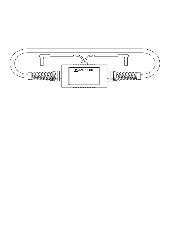
DESCRIPTION
The ATGC-1 Ground Coil (Fig. 1) allows the signal from the Transmitter in the Advanced Tracer
AT2000 and AT-4005CON series to be induced onto buried conductors, water pipes, and gas
pipes up to 6 feet deep. This allows tracing of conductors up to 300 feet in length.
SETUP AND INDUCTIVELY COUPLED SIGNALS
The initial setup of the ATGC-1 to achieve maximum signal induction is accomplished easier
if two people participate. One person to hold the receiver and one person to adjust the coil
position.
Since the ATGC-1 creates a large field, it is possible that the field may be induced onto
other known or unknown conductors in the area. By rewinding or recoiling the ATGC-1 so
the overall diameter of the coil is smaller, the field will become smaller and may eliminate
coupling to adjacent conductors in the area.
The conductor with the lowest resistance, has the most current flowing through it or has the
largest mass, will carry the greatest signal. Underground conductors must be grounded on
both ends or have current flowing through them in order for a signal current to flow. The
Receiver must be set to the “Short” mode in order to sense this signal.
The Receiver should only be set to the “OPEN” MODE if the conductor is not grounded on
both ends and no earth shield is present between the conductor and receiver.
Refer to the manual
Dangerous Voltage
Earth Ground
Audible tone
Complies with EU directives
Underwriters Laboratories.
5
Page 7

WARNING
If the Receiver does not pick up a signal it does not necessarily mean that the area is safe
for excavating. It is possible that live conductors that do not have current flowing through
them or are not grounded at both ends, do not effectively couple the signal. Extra measures
should be taken to insure that a safety hazard does not exist before any excavating begins.
It is advisable to use the Rechargeable Battery Pack Model B2024 when using the Ground Coil
as it allows a deeper and three times more signal to be induced for longer tracing distances.
Placing the coil directly over the conductor is not recommended, as minimal signal induction
will occur.
TRACING UNDERGROUND CONDUCTORS, WATER PIPES AND GAS PIPES
Setup
Look around and observe your surroundings. Setup the coil in the area that the conductor 1.
most likely would be buried, approximately 30’ away from where you want to start
identifying the location of the conductor.
Arrange the ATGC-1 Ground Coil in a circle on the ground approximately 3’ from the top 2.
center of the conductor or pipe (Fig. 2). Note: Placing the coil directly over the conductor
will not induce any signal.
Plug the ATGC-1 Ground Coil (A) and B2024 Battery Pack (D) into the Transmitter (E).3.
Set the Transmitter to the “HIGH” MODE and turn the unit “ON”.4.
At a distance of 25–30 ft from the coil, point the Receiver (C) perpendicular to the ground 5.
with the front label and Signal Strength Indicator facing the coil. If you do not get far
enough away from the coil, the receiver will only pick up the signal radiating through the
air off the coil itself.
Set the Receiver to the “SHORT” MODE and set the Range selector switch to X100 6.
(AT-2000 series only).
Turn the Receiver on by rotating the thumbwheel and set it to 5 (AT-2000 series only).7.
Finding the Conductor(s)
While maintaining a 25–30 ft radius from the coil, trace the area in a circular pattern, 8.
remembering to keep the Receiver perpendicular to the ground with the front label and
Signal Strength Indicator facing the coils as you are circling the coil (Fig. 3). Individual
short “ghost” signals may be received while moving in this circular direction. This is
normal and due to stray signal current. If you stop moving you will realize that there is
no real signal present. The real signal radiating off the conductor will continually pulse.
Multiple signals may indicate multiple conductors. Locate the area in which the maximum
signal strength is displayed on the conductor you wish to trace
Positioning Coil for best signal Induction
When the area of the maximum signal is located, place the Receiver (E) probe tip against 9.
the ground on the centerline (D) of the conductor (F). With the Receiver held in place,
have your partner incrementally adjust the position of the ground coil to the left or right
of its original position to further increase the signal strength displayed on the Receiver.
Adjust the sensitivity down if the Receiver full scale deflects.
Once the coil is positioned to induce the absolute maximum signal. You may turn from 10.
the coil and begin tracing the conductor away from the calibration point, by moving the
receiver back and forth in a pendulum motion, adjusting the sensitivity as necessary. Mark
the ground with paint or chalk where the maximum signal is received.
6
Page 8

Remember to keep the receiver tip straight down, perpendicular to the ground with
the front label and signal strength indictor facing the direction of the conductor run. To
trace pipes or conductors over long distances, move the coil to the place where the signal
dropped off and repeat the procedure.
TECHNICAL SPECIFICATIONS
Coil Diameter 1m (3.28 ft)
Operating Frequency 32.758 kHz
Field Radius (air) 7.62–9.14m (25–30 ft) With B2024
Termination Shrouded Male Banana Plugs (Integrated)
Operating Temperature 32˚–120˚F (0˚–48.8˚C)
Weight 0.68 kg (1.5 lbs)
7
Page 9

A ATGC-1 Ground Coil
B Conductor or Pipe
C Receiver
Fig. 2 – Proper distance for initial setup.
D B2024 Battery Pack
E Transmitter
F Top Center of conductor
or pipe
A ATGC-1 Ground Coil
B Conductor or Pipe
Fig. 3 – Locating the area of maximum signal strength
C Maximum Signal Strength
D Little or no signal strength
8
Page 10

A Maximum induction
B Less induction
C Calibration Point
Fig. 4 – Conductor centerline and Coil position adjustment
D Conductor Centerline
E Face Receiver towards coil
F Conductor
9
Page 11

10
Page 12

Visit www.Amprobe.com for
Catalog•
Application notes•
Product specifications•
User manuals•
Please Recycle
 Loading...