


AT-8000
Advanced Wire Tracers
AT-8020
AT-8030
User Manual
ENG FRE
TIP
SENSOR
CAT IV 600V AC
NCV
SPA
AT-8000-R
AT-8000-T


AT-8000
Advanced Wire Tracer
AT-8020
AT-8030
User Manual
English
3/2020, 6012207 A
©2020 Amprobe.
All rights reserved.

Limited Warranty and Limitation of Liability
Your Amprobe product will be free from defects in material and workmanship for one year from
the date of purchase unless local laws require otherwise. This warranty does not cover fuses,
disposable batteries or damage from accident, neglect, misuse, alteration, contamination, or
abnormal conditions of operation or handling. Resellers are not authorized to extend any other
warranty on the behalf of Amprobe. To obtain service during the warranty period, return the
product with proof of purchase to an authorized Amprobe Service Center or to an Amprobe
dealer or distributor. See Repair Section for details. THIS WARRANTY IS YOUR ONLY REMEDY.
ALL OTHER WARRANTIES - WHETHER EXPRESSED, IMPLIED OR STATUTORY - INCLUDING IMPLIED
WARRANTIES OF FITNESS FOR A PARTICULAR PURPOSE OR MERCHANTABILITY, ARE HEREBY
DISCLAIMED. MANUFACTURER SHALL NOT BE LIABLE FOR ANY SPECIAL, INDIRECT, INCIDENTAL
OR CONSEQUENTIAL DAMAGES OR LOSSES, ARISING FROM ANY CAUSE OR THEORY. Since some
states or countries do not allow the exclusion or limitation of an implied warranty or of incidental
or consequential damages, this limitation of liability may not apply to you.
Repair
All Amprobe products returned for warranty or non-warranty repair or for calibration should
be accompanied by the following: your name, company’s name, address, telephone number,
and proof of purchase. Additionally, please include a brief description of the problem or
the service requested and include the test leads with the meter. Non-warranty repair or
replacement charges should be remitted in the form of a check, a money order, credit card
with expiration date, or a purchase order made payable to Amprobe.
In-warranty Repairs and Replacement – All Countries
Please read the warranty statement and check your battery before requesting repair. During
the warranty period, any defective test tool can be returned to your Amprobe distributor for an
exchange for the same or like product. Please check the “Where to Buy” section on amprobe.com
for a list of distributors near you. Additionally, in the United States and Canada, in-warranty repair
and replacement units can also be sent to an Amprobe Service Center (see address below).
Non-warranty Repairs and Replacement – United States and Canada
Non-warranty repairs in the United States and Canada should be sent to an Amprobe Service
Center. Call Amprobe or inquire at your point of purchase for current repair and replacement rates.
USA: Canada:
Amprobe Amprobe
Everett, WA 98203 Mississauga, ON L4Z 1X9
Tel: 877-AMPROBE (267-7623) Tel: 905-890-7600
Non-warranty Repairs and Replacement – Europe
European non-warranty units can be replaced by your Beha-Amprobe distributor for a
nominal charge. Please check the “Where to Buy” section on beha-amprobe.com for a list of
distributors near you.
Beha-Amprobe
Division and reg. trademark of Fluke Corp. (USA)
Germany* United Kingdom
In den Engematten 14 52 Hurricane Way Science Park Eindhoven 5110
79286 Glottertal Norwich, Norfolk 5692 EC Son
Germany NR6 6JB United Kingdom The Netherlands
Phone: +49 (0) 7684 8009 - 0 Phone: +44 (0) 1603 25 6662 Phone: +31 (0) 40 267 51 00
beha-amprobe.de beha-amprobe.com beha-amprobe.com
*(Correspondence only – no repair or replacement available from this address. European
customers please contact your distributor.)
**single contact address in EEA Fluke Europe BV
The Netherlands - Headquarters**

AT-8000 Advanced Wire Tracer
CONTENTS
1. PRECAUTIONS AND SAFETY MEASURES ............................................................. 2
2. KIT COMPONENTS ................................................................................................. 5
2.1 AT-8000-R Receiver ........................................................................................................6
2.2 AT-8000-T Transmitter ...................................................................................................8
2.3 CT-400 Signal Clamp ......................................................................................................11
3. MAIN APPLICATIONS ............................................................................................ 12
3.1 Tracing Energized Wires .................................................................................................13
TM
• Using the Receiver in Energized SMART SENSOR
• Using Receiver in Energized TIP SENSOR mode ........................................................ 15
3.2 Tracing De-Energized Wires ...........................................................................................16
• Using Receiver in De-Energized TIP SENSOR mode
3.3 Identifying Breakers and Fuses ......................................................................................17
• Using Receiver in Energized & De-Energized Breaker mode
3.4 Non-Contact Voltage Mode (NCV) ...............................................................................20
4. SPECIAL APPLICATIONS ........................................................................................ 21
4.1 GFCI-Protected Circuit Wire Tracing .............................................................................21
4.2 Finding Breaks/Opens ...................................................................................................22
4.3 Finding Shorts ...............................................................................................................22
4.4 Tracing Wires in Metal Conduit: Junction Box Method ..............................................23
4.5 Tracing Non-Metallic Pipes and Conduits ....................................................................23
4.6 Tracing Shielded Wires ..................................................................................................24
4.7 Tracing Underground Wires ..........................................................................................25
4.8 Tracing Low Voltage Wires and Data Cables ............................................................... 25
4.9 Sorting Bundled Wires ..................................................................................................26
4.10 Mapping a Circuit using Test Leads Connection .........................................................27
4.11 Tracing Breakers/Fuses on Systems with Light Dimmers ............................................27
4.12 Signal Clamp - Closed Loop Circuits ............................................................................28
4.13 Signal Clamp - Mapping Circuits ..................................................................................30
5. MAINTENANCE ...................................................................................................... 31
5.1 Battery Replacement ......................................................................................................31
5.2 Fuse Replacement ...........................................................................................................34
6. SPECIFICATIONS ..................................................................................................... 35
mode .......................................14
1

1. PRECAUTIONS AND SAFETY MEASURES
General
For your own safety and to avoid damage to the instrument we suggest you to follow the
procedures listed below:
NOTE: Before and during measurements be diligent to follow the instructions.
• Make sure that the electrical instrument is operating properly before use.
• Before attaching any of the conductors, make sure that the voltage present in the
conductor is in the range of the instrument.
• Keep the instruments in their carrying case when not in use.
• If the Transmitter or Receiver will not be used for a long time, remove the batteries to
prevent leakage in the instruments.
• Use Amprobe approved cables and accessories only.
Safety precautions
In many instances, dangerous levels of voltage and/or current may be present. Therefore, it
is important to avoid direct contact with any uninsulated voltage/current carrying surfaces.
Insulated gloves and protective clothing should be worn in hazardous voltage areas.
• Do not measure voltage or current in wet, damp or dusty places.
• Do not measure voltage in the presence of gas, explosive materials or combustibles.
• Do not touch the circuit under test if no measurement is being taken.
• Do not touch exposed metal parts, such as unused terminals and circuits.
• Do not use the instrument if it appears to be malfunctioning (i.e. if you notice
deformations, breaks, leakage of substances, absence of messages on the display, etc).
Safety information
The product complies with:
• UL/IEC/EN 61010-1, CAN/CSA C22.2 No. 61010-1, Pollution Degree 2, Measurement
category IV 600 V MAX
• IEC/EN 61010-2-030
• IEC/EN 61010-2-032
• IEC/EN 61010-031 (test leads)
• EMC IEC/EN 61326-1
Measurement Category IV (CAT IV) is for circuits that are directly connected to the primary
utility power source for a given building or between the building power supply and the
main distribution board. Such equipment may include electricity tariff meters and primary
over current protection devices.
Measurement Category II (CAT II) is for measurements performed on circuit directly
connected to the low voltage installation. Examples are measurements on house hold
appliances, portable tools and similar equipment.
CENELEC Directives
The instruments conform to CENELEC Low-voltage directive 2014/35/EU and Electromagnetic
compatibility directive 2014/30/EU.
2

1. PRECAUTIONS AND SAFETY MEASURES
�Warnings: Read Before Using
To avoid the possibility of electric shock or personal injury:
• Use the Product only as specified in this manual or the protection provided by the
instrument may be compromised.
• Avoid working alone so assistance can be rendered.
• Test on a known signal source within the rated voltage range of the Product both before
and after use to ensure the Product is in good working conditions.
• Do not use the Product around explosive gas, vapor, or in damp or wet environments.
• Inspect the Product before use and do not use if it appears damaged. Check for cracks or
missing plastic. Pay particular attention to the insulation around the connectors.
• Inspect the test leads and other accessories before use. Do not use if insulation is
damaged or metal is exposed.
• Do not use the Product if it operates incorrectly. Protection may be impaired. When in
doubt, have the Product serviced.
• Check the test leads for continuity. Replace damaged test leads before using the Product.
• Have the Product serviced only by qualified service personnel.
• Use extreme caution when working around bare conductors or bus bars. Contact with
the conductor could result in electric shock.
• Do not hold the Product beyond the tactile barrier.
• Do not apply more than the rated voltage and CAT rating, as marked on the Product,
between the terminals or between any terminal and earth ground.
• Remove test leads from the Product before opening the Product case or battery cover.
• Never operate the Product with the battery cover removed or the case open.
• Use caution when working with voltages above 30 V AC RMS, 42 V AC peak, or 60 V DC.
These voltages pose a shock hazard.
• Do not exceed the Measurement Category (CAT) rating of the lowest rated individual
component of a Product, probe, or accessory.
• Do not attempt to connect to any circuit carrying voltage that may exceed the maximum
range of the Product.
• Use the proper terminals, functions and ranges for your measurements.
• When using alligator clips and test probes, keep fingers behind the finger guards.
• Use only exact fuse replacement and specified replacement parts.
• When making electrical connections, connect the common test lead before connecting
the live test lead; when disconnecting, disconnect the live test lead before disconnecting
the common test lead.
• To avoid false readings that can lead to electrical shock and/or injury, replace the
batteries as soon as the low battery indicator appears. Check Product operation on a
known source before and after use.
• Use only AA batteries, properly installed in the Product case, to power the Product (see
Section 5.1: Battery Replacement).
• When servicing, use only specified user serviceable replacement parts.
• Adhere to local and national safety codes. Individual protective equipment must be used
to prevent shock and arc blast injury where hazardous live conductors are exposed.
• Only use the test lead provided with the Product or UL Listed Probe Assembly rated
CAT IV 600 V or better.
• Do not use the HOT STICK (TIC 410A) to operate the AT-8000-R Receiver at voltages above 600 V.
• Remove the batteries if the Product is not used for an extended period of time, or if
stored in temperatures above 122 °F (50 °C). If the batteries are not removed, battery
leakage can damage the Product.
• Follow all battery care and charging instructions from the battery manufacturer.
• Do not use the Product to check for absence of voltage. Please use an appropriate voltage
tester instead.
3

1. PRECAUTIONS AND SAFETY MEASURES
Symbols used in this product
Battery status – Displays the remaining battery charge.
Home – Return to home screen when selected.
Help – Enters to the help guide when selected.
Settings – Enters to the settings menu when selected.
Indicates the volume is muted.
Volume – Displays the volume in four levels.
Sensitivity indicator – Displays the sensitivity level from 1 to 10.
Icon indicating energized system.
Icon indicating de-energized system.
99
Signal strength indicator – Shows the strength of the signal
from 0 to 99.
SIGNAL
MAN/AUTO
Shows whether the sensitivity adjustment is in Manual or Automatic mode.
Lock indicates if the Auto sensitivity lock is active
(Only in Auto sensitivity mode).
Application and removal from hazardous live conductors permitted.
�
T
J
CAT IV 600V
I
)
P
=
Caution! Risk of electric shock.
Caution! Refer to the explanation in this Manual.
The equipment is protected by double insulation or reinforced insulation.
Earth (Ground).
Overvoltage up to Category IV 600V (transient protection up to 8 kV).
Fuse.
Conforms to relevant North American Safety Standards.
Complies with European Directives.
Conforms to relevant Australian standards.
This product complies with the WEEE Directive marking requirements. The
affixed label indicates that you must not discard this electrical/electronic
product in domestic household waste. Product Category: With reference
to the equipment types in the WEEE Directive Annex I, this product is
classed as category 9 “Monitoring and Control Instrumentation” product.
Do not dispose of this product as unsorted municipal waste.
4

1. PRECAUTIONS AND SAFETY MEASURES
This manual contains information and warnings that must be followed for safe operation
and maintenance of the instrument. If the Product is used in a manner not specified by the
manufacturer, the protection provided by the Product may be impaired. This Product meets
water and dust protection IP52 (Receiver) and IP40 (Transmitter and signal clamp) per
IEC 60529. Do NOT operate outside during periods of rainfall. The Product is double insulated
for protection per EN 61010-1 to CAT IV 600 V.
CAUTION: Do not connect the Transmitter to a separate ground in Electrically Susceptible
Patient areas of a health care facility. Make the ground connection first and disconnect it last.
2. KIT COMPONENTS
Your shipping box should include:
AT-8020 KIT AT-8030 KIT
AT-8000-R RECEIVER 1 1
AT-8000-T TRANSMITTER 1 1
TL-8000-INT TEST LEAD AND ACCESSORY KIT* 1 1
CC-8000 HARD CARRYING CASE 1 1
BATTERY CHARGERS - 3
RECHARGEABLE BATTERIES NIMH TYPE 1.2 V AA
(IEC LR6)
BATTERIES ALKALINE 1.5 V AA (IEC LR6) 12 CT-400 SIGNAL CLAMP - 1
HS-1 MAGNETIC HANGER - 1
USER MANUAL 1 1
QUICK START GUIDE 1 1
- 12
*TL-8000-INT test lead and accessory kit includes:
• 2 x 1 m test leads (red, black): CAT IV 600 V
• 1 x 7 m test lead (green): CAT IV 600 V
• 2 x Alligator clips (red, black): CAT IV 600 V
• 2 x Outlet blade adapters (red, black): CAT II 300 V
• 2 x Outlet round adapters (red, black): CAT II 300 V
Optional Accessories:
• TL-8000-25M 25 m test lead
• ADPTR-SCT Socket adapter
• HS-1 Magnetic hanger
• CT-400 Signal clamp
5

2. KIT COMPONENTS
2.1 AT-8000-R Receiver
The AT-8000-R Receiver detects the signal generated by the AT-8000-T Transmitter along
wires using either the Tip Sensor or Smart SensorTM and displays this information on the full
color TFT LCD display.
Active tracing using a signal generated by the AT-8000-T Transmitter
The Smart SensorTM works with a 6 kHz signal generated along Energized wires (above 30 V
AC/DC) and provides an indication of the wire position and direction relative to the Receiver.
The Smart SensorTM is not designed to work on De-energized systems; for that application
the Tip Sensor should be used in De-energized mode.
The Tip Sensor may be used on either Energized or De-energized wires and can be used for
general tracing, tracing in tight spaces, locating breakers/fuses, pinpointing wires in bundles
or in junction boxes. The TIP SENSOR mode will pinpoint the wire location with both an
audible and visual indication of detected signal strength, but unlike SMART SENSOR
it will not provide wire direction or orientation.
Note: The Receiver will NOT detect signals from the wire through metal conduit or shielded
cable. Refer to Special Applications, section 4.4 “Tracing Wires In Metal Conduit” for
alternative tracing methods.
TIP SENSOR
TM
mode
SMART SENSOR
TM
(Back side)
TACTILE BARRIER
NCV BUTTON
Non-Contact
Voltage mode
NAVIGATION KEYS
4-WAY
RUBBER OVER
MOLDED ENCLOSURE
LCD DISPLAY
Full color TFT display
TACTILE BARRIER
SENSITIVITY ADJUSTMENT
BUTTON (-/+)
ENTER BUTTON
Selects the function
POWER BUTTON
BATTERY COMPARTMENT
(Back side)
HOT STICK ATTACHMENT POINT
(Do not use for voltage higher
than 600 V)
Figure 2.1a: Overview of AT-8000-R Receiver
6

2. KIT COMPONENTS
Main
applications
ENERGIZED:
DE-ENERGIZED:
Battery
status
Help guide
Setting menu
Buzzer volume adjustment
Figure 2.1b: Overview of home screen elements
Home menu
Language English, French, Spanish, Portuguese
Backlight 25%, 50%, 75%, 100%
Setting
Help Guidance
Sensitivity*
Smart Sensor
Range
*Note: The Auto and Manual sensitivity mode can be easily changed by pressing the + and
– key at the same time when the Receiver is in a tracing mode. When sensitivity mode is set
to “Auto” manual adjustment is disabled.
Figure 2.1c: Overview of settings menu elements
DEFAULT
ON
OFF : Device will start without guidance
MAN
TM
AUTO : Auto sensitivity adjustment
SHORT
LONG : For wire detection between 3 and 20 feet
: Restore default settings
: Device will guide you through each mode
: Manual sensitivity adjustment (+) and (-) keys
: For wire detection up to 3 feet
x.x.x
--
Sensitivity adjustment
x.x
7

2. KIT COMPONENTS
2.2 AT-8000-T Transmitter
The AT-8000-T Transmitter works on Energized and De-energized circuits up to 600 V AC/DC
in Category I through Category IV electrical environments.
VOLTAGE WARNING
INDICATOR
1. Red: Energized
2. Off: De-energized
3. Blinking: Overvoltage
VOLUME
ADJUSTMENT
BUTTON (+/-)
AT-8000-T
TRANSMITTER
TRANSMISSION MODE
INDICATOR
LOOP MODE INDICATOR
RUBBER OVERMOLDED
ENCLOSURE
HI
LO
MUTE INDICATOR
HIGH SIGNAL MODE
Press >2s for Loop mode
LOW SIGNAL
(PRECISION) MODE
POWER BUTTON
BATTERY STATUS
Figure 2.3: Overview of AT-8000-T Transmitter
ON/OFF: Short press to turn the Transmitter on. Long press >2s to turn the Transmitter off.
Volume adjustment: The volume can be changed by short presses on VOLUME UP/DOWN
buttons. In addition to mute, four volume levels are available. The chosen volume level will
be shown on LED display for a short time. If sound is muted, the MUTE LED light will be on.
The sound pattern is different depending on chosen operating mode.
Voltage Warning indicator: The warning light will be ON for Energized circuits (30 to 600 V
AC/DC), OFF for De-energized circuits (0 to 30 V AC/DC), and BLINKING if an overvoltage is
detected (> 650 V AC/DC).
TRANSMISSION MODE INDICATOR: The LEDs will blink with different rhythm depending on the
chosen operating mode.
Transmitting in HIGH mode – Fast blinking
Transmitting in LOW mode – Slow blinking
Transmitting in LOOP mode – Alternating blinking
High mode: Short press on HI to turn on HIGH transmitting mode. Second short press on HI
button to turn off transmitting.
Low mode: Short press on LO to turn on LOW transmitting mode. Second short press on LO
button to turn off transmitting.
Loop mode: Long press (>2s) on HI to turn on Loop mode. Short or long press on HI button
to turn off Loop mode.
8

2. KIT COMPONENTS
Transmitter signal modes:
High Signal (Hi) – The HIGH mode function is recommended for most wire tracing
applications on Energized and De-energized circuits including breaker/fuse location. This
function will be used the majority of the time.
Low Signal (Lo) – The LOW mode function is only appropriate for the most demanding and
precise wire tracing applications, as it limits the signal level generated by the Transmitter
in order to pinpoint the wire location more precisely. A lower signal level reduces coupling
to neighboring wires and metal objects, which avoids misreadings due to ghost signals. A
lower signal also prevents oversaturating the Receiver with a strong signal that covers too
large of an area.
Loop mode – This mode is initiated by pressing and holding the HI button for >2 seconds. It
should be used when working with closed loop De-energized circuits, such as shorted wires,
shielded cables or De-energized wires that are grounded on the far-end.
How is the Loop function different from the Hi or Lo settings when using test leads?
Both HIGH and LOW modes generate a signal in all open branches of the De-energized
circuit. This is useful when tracing open wires. Hi/Lo modes will NOT work on wires that are
shorted (closed loop) or grounded on the far-end because the signal cannot be generated.
CAT IV 600V AC
TIP
SENSOR
CAT IV 600V AC
TIP
SENSOR
Figure 2.2a: Generating a signal with HIGH and LOW modes and closed loop
Loop mode generates a signal (current flow) in closed loop De-energized circuits only. Loop
mode is used to pinpoint the location of a short (because the current will not be able to
flow in open branches) and to trace wires that are grounded on the far end (because the
loop is closed via ground connection).
CAT IV 600V AC
TIP
SENSOR
CAT IV 600V AC
TIP
SENSOR
Figure 2.2b: Generating a signal in Loop mode
Note: Loop mode only works on De-energized circuits. However the receiver needs to be set
to Energized sensor mode (the transmitter creates safe low voltage state). It is automatically
disabled when the Transmitter is connected to an Energized line with test leads.
9

2. KIT COMPONENTS
Working with the Transmitter
When the Transmitter is on and connected to the circuit with test leads, it checks for
voltage. A red Voltage Warning Indicator will light up if the Transmitter detects dangerous
voltage levels above 30 V AC/DC.
IMPORTANT!
The Voltage Warning Indicator light will blink when overvoltage (> 650 V AC/DC) is
detected. In case of overvoltage immediately disconnect the Transmitter from the circuit.
This Voltage Waning Indicator is not desinged to check for absence of voltage. Please use a
voltage tester therefore.
If the High (HI) or Low (LO) Signal button is pressed momentarily, the Transmitter starts
generating a tracing signal. Based on the detected voltage, the Transmitter automatically
switches to either:
• Energized mode (30 to 600 V AC/DC) generating 6 kHZ frequency
• De-energized mode (0 to 30 V AC/DC) generating 33 kHz frequency
Energized mode uses a lower transmission frequency (6 kHz) than De-energized mode
(33 kHz) to reduce signal coupling between wires. De-energized mode requires a higher
frequency in order to generate a reliable signal.
Energized mode: In Energized mode, the Transmitter draws a very low current from the
Energized circuit and generates a 6 kHz signal. This is a very important feature of the
Transmitter, since drawing current does not inject any signal that would harm sensitive
equipment connected to the circuit. The signal is also generated in a direct path between
the Transmitter and the power source, thus NOT placing a signal onto any branches enabling
wiring tracing directly back to the breaker/fuse panel. Please note that due to this feature,
the Transmitter has to be connected on the load side of the circuit.
De-energized mode: In De-energized mode, the Transmitter injects a 33 kHz signal onto
the circuit. In this mode, the signal will travel though all the circuit branches because it is
injected. The high frequency/low energy signal will not harm any sensitive equipment.
10

2. KIT COMPONENTS
2.3 CT-400 Signal Clamp
(included with AT-8030, optional for AT-8020)
The Signal Clamp accessory is used for applications when where is no access to the bare
conductors. The clamp attachment enables the Transmitter to induce a signal through the
insulation into either wires. The clamp works on low impedance closed circuits.
CONNECTORS TO
TRANSMITTER
JAW
TACTILE
BARRIER
JAW
RELEASE
TEST LEAD
Figure 2.3: Overview of CT-400 Signal Clamp
11

3. MAIN APPLICATIONS
� IMPORTANT NOTICE, PLEASE READ BEFORE STARTING TRACING
Avoiding signal cancellation problems with a separate ground connection
The signal generated by the Transmitter creates an electromagnetic field around the wire.
This field is what is detectable by the Receiver. The clearer this signal, the easier it is to trace
the wire.
If Transmitter is connected to two adjacent wires on the same circuit (for example, hot and
neutral wires on a Romax cable), the signal travels in one direction through the first wire
and then returns (in opposite direction) through the second. This causes the creation of two
electromagnetic fields around each wire with opposite direction. These opposing fields will
partially or completely cancel each other out, making wire tracing difficult if not impossible.
AT-8000-T
To avoid the cancellation effect, a separate ground connection method should be used.
The red test lead of the Transmitter should be connected to the hot wire of the circuit you
wish to trace, and the green lead to a separate ground, such as water pipe, ground stake,
metal grounded structure of the building, or outlet ground connection of an outlet on a
different circuit. It is important to understand that an acceptable separate ground is NOT
the grounding terminal of any receptacle on the same circuit as the wire you wish to trace.
If hot wire is Energized and the Transmitter is properly connected to a separate ground,
the red LED on the Transmitter will light up. The separate ground connection creates
maximum signal strength because the electromagnetic field created around the hot wire is
not being cancelled by a signal on the return path flowing along an adjacent wire (hot or
neutral) in the opposite direction, but rather through the separate ground circuit.
12
AT-8000-T

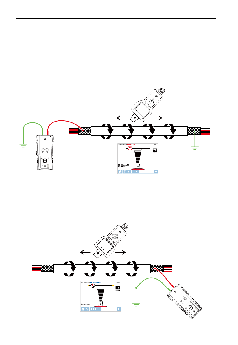
3. MAIN APPLICATIONS - ENERGIZED WIRES
3.1 Tracing Energized Wires
Connecting Transmitter test leads
1. Connect the green and red test leads to the
Transmitter (polarity does not matter).
2. Using provided test leads accessories, connect
the green wire to a separate ground (metal
AT-8000-T
building structure, metal water pipe, or ground
wire on a separate circuit).
3. Connect the red test lead to the line/phase wire
being traced. For Energized systems the signal
will ONLY be transmitted between the load-side
to which the Transmitter is connected and the
source of power (see Figure 3.1a)
*Note: Please note that if working with GFCI
protected circuits, this method will trip the GFCI
protection. Refer to Special Applications,
section 4.1 “GFCI-Protected Circuit Wire Tracing”
Proper connection with separate ground
Figure 3.1a:
for alternative tracing methods.
TIP: The Transmitter, with the red test lead, can be directly connected to the live wire
of the working electrical equipment under load (motor, electronics, etc). Tracing can
be performed without needing to turn off the equipment or switching power off.
SMART SENSOR
TM
AT-8000-T
Figure 3.1b: Transmitter set up
Set up the AT-8000-T Transmitter
1. Press power button to turn on the Transmitter.
2. Verify that the test leads are properly connected; the red LED voltage status light should be
on for circuits with voltage above 30 V AC/DC.
Note: Make sure to use the separate neutral connection as described above.
3. Select HIGH signal mode by pressing HI for most applications. The Transmitter will appear
as shown in Figure 3.1c. The LED display will quickly begin to blink.
13

3. MAIN APPLICATIONS - SMART SENSORTM (Energized)
AT-8000-T
TRANSMITTER
Note: The LOW signal precision mode can be
used to limit the signal level generated by the
Transmitter in order to more precisely pinpoint
wire location. A lower signal level reduces
coupling to neighboring wires and metal objects
TM
and helps to avoid misreading due to ghost
signals. A lower signal also helps to prevent
oversaturating the Receiver with a strong signal
that covers too large an area. The LOW mode
function is only used for the most demanding
and precise wire tracing applications.
SMART SENSOR
HI
LO
Figure 3.1c: Transmitter indicator
showing signal in HIGH mode
Using AT-8000-R Receiver in Energized SMART SENSORTM mode
The Smart SensorTM enables easier wire tracing by showing the direction and position of the
wire and is the recommended method for tracing Energized wires.
Note: The Smart SensorTM does not work on de-energized circuits; Tip Sensor should be
used instead.
Using AT-8000-R Receiver
1. Press power button to turn on the Receiver; home screen may take up to 30 seconds to load.
2. Select SMART SENSORTM mode by using the directional arrows and pressing the yellow
ENTER button.
3. Hold the Receiver with the Smart Sensor
a red target then either no signal is detected or the signal is not adequate enough to display
direction. (Figure 3.1d). Move the Smart SensorTM closer to the target area until the signal is
detected and you see a directional arrow. If no signal is detected increase the sensitivity using
the “+” button on the Receiver.*
4. Move the Receiver in direction indicated by the arrow on the screen (Figure 3.1e).
5. A green target symbol indicates that the Receiver is directly over the wire (Figure 3.1f).
If the Receiver does not lock on the wire, decrease sensitivity using the “-“ on the
keypad or set the Transmitter to transmit at LOW level for precision tracing.
6. Press ENTER when complete to return to the home screen.
*Note: For best results, keep the Receiver at least 3 feet from the Transmitter and its test leads
to minimize signal interference and improve wire tracing results. Select the “Long” Smart
SensorTM Range in the Settings Menu if working with wires that are greater than 3 feet deep.
TM
facing the target area. If the screen flashes a “?” in
BLINKING
Figure 3.1d: No signal detected
Figure 3.1e: Wire is to the left
14

3. MAIN APPLICATIONS - TIP SENSOR (Energized)
-
-
Figure 3.1f: Receiver locked on wire
Using AT-8000-R Receiver in Energized TIP SENSOR mode
TIP SENSOR mode is used for the following applications: pinpointing a wire in a bundle,
tracing in corners and confined spaces such as junction boxes or inside enclosures.
1. Press power button to turn on the Receiver; home screen may take up to 30 seconds to load.
2. Select Energized TIP SENSOR mode by using the directional arrows and pressing the
yellow ENTER button.
3. Hold the Receiver with the Tip Sensor facing the target area.
4. Scan target area with Tip Sensor to find highest signal level (Figure 3.1g). While tracing,
periodically adjust sensitivity to keep signal strength near 75. Increase or decrease sensitivity
by pressing + or – on the keypad. If signal is too strong for precise locating, change
transmitter to LOW mode.
5. Receiver Positioning: For best results, align groove on Tip Sensor with wire direction.
Signal may be lost if not properly aligned (Figure 3.1h).
6. To verify wire direction, periodically rotate the Receiver 90 degrees. Signal strength will
be highest when wire is aligned with Tip Sensor groove (Figure 3.1i).
7. Press ENTER when complete to return to the home screen.
Note: For best results, keep the Receiver at least 3 feet (1 m) from the Transmitter and its
test leads to minimize signal interference and improve wire tracing results.
TIP SENSOR
TIP SENSOR ENERGIZED
75
SIGNAL
30-600V AC/DC
40-400 HZ
Figure 3.1g: Receiver screen showing signal
detected in Energized TIP SENSOR mode
15

3. MAIN APPLICATIONS - TIP SENSOR (Energized)
AT-8000-T
TRANSMITTER
Align
TIP SENSOR
Tip groove
Aligning the Tip Sensor with the wire
3.2 Tracing De-energized Wires
Connecting Transmitter test leads
1. Connect the green and red test leads to the
Transmitter (polarity does not matter).
2. Using provided test leads, connect the green
wire to a separate ground (metal building
structure, metal water pipe, or ground wire on a
separate circuit) (Figure 3.2a).
3. Connect the red test lead to the wire being
traced. For receptacles, make sure to connect
the test lead to the line (hot De-energized) wire.
For De-energized systems the signal will be
transmitted across all branches of the circuit.
Set up the AT-8000-T Transmitter
1. Press power button to turn on the Transmitter.
2. Verify that the test leads are properly connected; the red
LED voltage status light should be off for De-energized
circuits below 30 V AC/DC.
Note: Make sure to use the separate ground
connection as described above.
3. Select HIGH signal mode by pressing HI for most
applications. The Transmitter will appear as shown in
Figure 3.2b. The LED display will quickly begin to blink.
Note: The LOW signal precision mode can be used to limit
the signal level generated by the Transmitter in order to
more precisely pinpoint wire location. A lower signal level
reduces coupling to neighboring wires and metal objects
and helps to avoid misreading due to ghost signals. A
lower signal also helps to prevent oversaturating the
Receiver with a strong signal that covers too large an
area. The LOW mode function is only used for the most
demanding and precise wire tracing applications.
Figure 3.1h:
16
Figure 3.1i:
Rotating the Receiver to
align with the wire
AT-8000-T
Figure 3.2a: Proper connection with
separate ground
BLINKING
HI
LO
Figure 3.2b: Transmitter indicator
showing signal in HIGH mode

3. MAIN APPLICATIONS - TIP SENSOR (De-Energized)
-
-
Using AT-8000-R Receiver in De-energized TIP SENSOR mode
TIP SENSOR
De-energized TIP SENSOR mode is used for general wire tracing, pinpointing wires in bundles,
tracing in tight corners and confined spaces such as junction boxes or inside enclosures.
1. Press power button to turn on the Receiver; home screen may take up to 30 seconds to load.
2. Select De-Energized TIP SENSOR mode by using the directional arrows and pressing the
yellow ENTER button.
3. Hold the Receiver with the Tip Sensor facing the target area.*
4. Scan target area with Tip Sensor to find highest signal level (Figure 3.2c). While tracing,
periodically adjust sensitivity to keep signal strength near 75. Increase or decrease
sensitivity by pressing + or – on the keypad. If signal is too strong for precise locating,
change transmitter to LOW mode.
5. Press ENTER when complete to return to the home screen.
TIP SENSOR DE-ENERGIZED
75
SIGNAL
0-30V AC/DC
TIP SENSOR
Figure 3.2c: Receiver showing signal detected in De-energized TIP SENSOR mode
*Note: For best results, keep the Receiver at least 3 feet (1 m) from the Transmitter and its
test leads to minimize signal interference and improve wire tracing results.
De-energized mode uses a different antenna in the Tip Sensor than Energized mode.
Specific alignment of the Tip Sensor groove to the wire is not required. De-energized wire
tracing results are based only on how close the Tip Sensor is to the wire.
3.3 Identifying Breakers and Fuses
Breaker mode automatically adjusts the sensitivity of the Receiver. As a result, the Receiver
will pinpoint and indicate just one correct breaker/fuse. This enhancement helps to remove
signal strength analysis from the breaker/fuse identification process that is typical for less
advanced wire tracers.
Note: For breaker/fuse locating, a simplified direct connection to hot and neutral wires can
be used because these wires are separated at the breaker/fuse panel. There is no risk of
signal cancellation effect if wires are at least a few inches away from each other. However,
the separate ground connection (Figure 3.3b) should be used for superior results specifically
if wires need to be traced in addition to breaker identification.
The simplified direct connection to hot and neutral wire will NOT trip the GFCI circuit.
17

3. MAIN APPLICATIONS - TIP SENSOR (De-Energized)
AT-8000-T
AT-8000-T
TIP SENSOR
Figure 3.3a: Simplified direct connection
Transmitter connection - Energized and De-energized systems
Connection of the Transmitter is the same for Energized and De-energized breaker/fuse locating.
Connecting the test leads
1. Connect the Transmitter using either simplified direct connection or separate ground connection.
2. If the simplified direct connection method is used, connect the test leads directly to
the hot and neutral wires. While locating a breaker, wires will not be traceable as the
signals will cancel each other out.
3. For separate ground connection, first connect the green lead to a separate ground, such
as a metal building structure, metal water pipe, or ground wire on a separate circuit.
4. Connect the red lead to the Energized hot wire on the load side of the system. The
signal will ONLY be transmitted between the outlet to which the Transmitter is
connected and the source of power.
Figure 3.3b: Separate ground connection
(Preferred)
AT-8000-T
Set up the AT-8000-T Transmitter
1. Press the power button to turn on the Transmitter.
2. Verify that the test leads are properly connected. The red LED voltage status light will
illuminate for Energized circuits with a voltage above 30 V AC/DC. If the voltage is
De-energized, the light will be off.
3. Select the HIGH signal mode for breaker/fuse locating.
18

3. MAIN APPLICATIONS - BREAKERS (Energized and De-Energized)
Energized and De-energized breaker/fuse locating
BREAKERS
Receiver Process Overview
Tracing breakers/fuses is a two-step process:
1
SCAN - Scan each breaker/fuse for one second. The Receiver will record tracing signal levels.
2
LOCATE - The Receiver will indicate the single breaker/fuse with the strongest recorded signal.
Using AT-8000-R Receiver
1. Press power button to turn on the Receiver; home screen may take up to 30 seconds to load.
2. Select either Energized BREAKERS mode or De-Energized BREAKERS mode by using the
directional arrows and pressing the yellow ENTER button.
&
BREAKERS &
Step 1 -
1. The unit will automatically start in
2. Scan each breaker/fuse for a second by touching it with the Tip Sensor. Make sure the
3. To assure sufficient time between the scans, wait for active green arrow and audible
4. Scan all breakers/fuses – the order of scanning does not matter. You can scan each
Usage tip: For best results try to scan at the output of the breaker/fuse.
Important note: Differentiation in breaker/fuse designs, height, internal contact structure may
affect precision of breaker/fuse identification. For most reliable results, remove the breaker/
fuse panel cover and perform scan on the wires instead of breakers/fuses. Scan the breakers/
fuses always at the same position and alignment of the Tip Sensor. A variation may affect
improper results.
1
SCAN
1
SCAN mode (Figure 3.3c).
groove on the Tip Sensor is parallel to the breaker/fuse lengthwise (Figure 3.3e).
alert (2 beeps) before moving to the next breaker/fuse.
breakers/fuses multiple times. The Receiver records the highest detected signal.
Figure 3.3c: SCAN mode –
Scanning breakers/fuses
Figure 3.3e: Correct alignment of
the Tip Sensor to the breaker
19

3. MAIN APPLICATIONS - BREAKERS (Energized)
Step 2 - 2 LOCATE
1. Select LOCATE mode by using the directional
arrows and pressing the yellow ENTER button
(Figure 3.3d).
2. Rescan each breaker/fuse by touching each
with the Tip Sensor for a second. Active red
arrow indicates scanning process. Make sure
the groove on the Tip Sensor is parallel to the
breaker/fuse lengthwise (Figure 3.3e).
Usage Tip: Hold receiver in the same position as
during scanning step
NCV MODE
3. Rescan all breakers/fuses until solid green arrow
and audible alert indicates that the correct breaker/
fuse was found (Figure 3.3f).
4. Press ENTER when complete to return to the home screen.
Usage Tip: The accuracy of breaker/fuse identification results can be verified by switching the
Receiver to Energized or De-Energized TIP SENSOR mode and checking that that the signal
level of the breaker identified by the Receiver is the highest among all breakers/fuses.
Figure 3.3d: LOCATE mode –
Searching for correct breakers/fuses
Figure 3.3f: LOCATE mode – breaker/fuse identified
3.4 NCV Mode
The NCV (Non-Contact Voltage) mode is used to verify that a wire is Energized. This method
does not require the use of the Transmitter. The Receiver will detect and trace an Energized
cable if the voltage is between 90 V and 600 V AC and between 40 Hz and 400 Hz. No current
flow is necessary.
Note: For safety, before working with wires, always verify that they are De-energized with
an additional voltage tester.
�The voltage indication in NCV mode is not sufficient to assure safety. This function is
not suitable to test for absence of voltage. This always requires a two-pole voltage test.
NCV mode operation
1. Press power button to turn on the Receiver; home screen may take up to 30 seconds to load.
2. Press NCV button to select the Non-Contact Voltage mode.
3. Hold the Receiver with the Tip Sensor against the wire.
4. For precise pinpointing of line/phase wire versus neutral wire, increase or decrease
sensitivity by pressing + or – on the keypad.
5. Press ENTER when complete to return to the home screen.
20

4. SPECIAL APPLICATIONS
Figure 3.4: Voltage detection in NCV mode using Tip Sensor
4.1 GFCI-Protected Circuit Wire Tracing
Connecting AT-8000-T Transmitter to GFCI protected circuits.
Connecting the Transmitter to an Energized GFCI protected circuit using separate ground
method will trip the GFCI protection. Use following methods to work with GFCI protected
circuits (for De-energized GFCI-protected outlet that is not tripped, you can connect test
leads directly to the outlet contacts using De-energized TIP SENSOR mode)
Method 1 – Bypass the GFCI circuitry to avoid tripping GFCI:
(for Energized GFCI-protected outlets only)
• Remove the protective receptacle wall plate.
• Using the alligator clip attach the red test lead to the screw connecting the Energized
hot wire to the receptacle.
• Connect the green test lead using separate ground method as described in Energized
TIP SENSOR mode.
• Perform tracing as described in one of the Energized modes: SMART SENSOR
SENSOR or BREAKER.
TM
, TIP
Method 2 – Do NOT use separate ground to avoid tripping GFCI:
(for GFCI-protected outlets and breakers)
• Connect Transmitter test leads to Neutral and Hot wires.
TM
• Perform tracing as described in one of the Energized modes: SMART SENSOR
, TIP
SENSOR or BREAKER.
Note: This type of connection causes signal coupling and reduces signal strength. If the
signal is too weak or untraceable, use Method 3.
Method 3 - De-energize the circuit:
(for GFCI-protected breakers)
• De-energize the circuit.
• Connect Transmitter directly to the wire as described in De-Energized TIP SENSOR mode.
• Perform tracing as described in the desired De-Energized mode (TIP SENSOR for wire
tracing or BREAKER for breaker identification).
21

4. SPECIAL APPLICATIONS
4.2 Finding Breaks/Opens
It is possible to pinpoint the exact location where a wire is broken, even if the wire is
located behind walls, floors or ceilings.
1. Make sure that wire is De-energized.
2. Use the steps described in section 3.2 to connect the Transmitter and perform tracing
with the Receiver set to De-energized TIP SENSOR mode.
3. For best results, ground all De-energized wires that run in parallel with the black test lead.
(Figure 4.2).
The tracing signal generated by the Transmitter is conducted along the wire as long as there is
continuity in the metal conductor. To find a fault, trace the wire until the signal stops. To verify
the fault’s location, move the Transmitter to the other end of the wire and repeat, tracing from
the opposite end. If signal stops at the exact same location, the fault has been located.
Note: If the place of the fault is not found, the result may be a high resistance break
(partially open circuit). Such a break would stop higher currents from flowing but will
conduct the tracing signal through the break. Such faults will not be detected until the wire
is completely open.
CAT IV 600V AC
TIP
SENSOR
Figure 4.2: Locating the place of the fault
4.3 Finding Shorts
Shorted wires will cause a breaker/fuse to trip. To correct this, disconnect the wires and
make sure the ends of the wires on both sides of the cable are isolated from each other and
other wires or loads and are De-energized.
1. Connect the Transmitter with the test leads to the circuit as shown in Figure 4.3.
2. Turn the Transmitter to Loop mode by pressing HIGH button for two seconds. Verify
that the Loop LED is ON.
3. Set the Receiver to Energized TIP SENSOR mode (the Transmitter will generate safe low
voltage tracing signal) and perform tracing.
Start tracing the cable until the signal stops. To verify the place of the fault, move the
Transmitter to the other end of the wire and repeat tracing from the opposite end. If the
signal stops at the exact same location the fault has been located.
Note: This method will be affected by signal cancellation effect. Expect a relatively weak signal.
22

4. SPECIAL APPLICATIONS
CAT IV 600V AC
TIP
SENSOR
Figure 4.3: Finding a short
4.4 Tracing Wires in Metal Conduit: Junction Box Method
The AT-8000-R Receiver will not be able to pick up the signal from the wire through the
metal conduit. The metal conduit will completely shield the tracing signal.
Note: The Receiver will be able to detect wires in non-metallic conduit. For these
applications follow general tracing guidelines.
In order to trace wires in conduit:
1. Use either Energized or De-energized TIP SENSOR mode as described in sections 3.1 and 3.2.
2. Open junction boxes and use the Receiver’s Tip Sensor to detect which wire in the
junction box is carrying the signal.
3. Move from junction box to junction box to follow the path of the wire.
Note: Applying signal directly to the conduit will send signal through all the conduit
branches making tracing of one particular conduit path not possible.
4.5 Tracing Non-Metallic Pipes and Conduits
The AT-8000 can indirectly trace plastic conduits and pipes using the following steps:
1. Insert conductive fish tape or wire inside the conduit.
2. Connect the Transmitter’s red test lead to the fish tape and the green ground wire to a
separate ground as described in section 3.2.
3. Set the Receiver to De-energized TIP SENSOR mode to trace the conduit.
4. The Receiver will pick up the signal conducted by fish tape or wire through the conduit.
23
4. SPECIAL APPLICATIONS
4.6 Tracing Shielded Wires
Shielded wires prevent the Receiver from detecting a tracing signal when following the
standard user instructions. To effectively trace shielded wire, follow these procedures.
If shielded wire is grounded at the far-end:
1. Setup Transmitter in Loop mode by pressing HIGH button for two seconds. Verify that
the Loop LED is ON.
2. Disconnect the ground on the near-end of the shielded wire and connect the shield to
one of the terminals of the Transmitter (polarity does not matter) with a test lead.
3. Connect the second output of the Transmitter to a separate ground.
4. Set the Receiver to De-energized TIP SENSOR mode to trace the shield as described in
section 3.2.
CAT IV 600V AC
TIP
SENSOR
Figure 4.6a: Tracing a shielded wire
If shielded wire is disconnected from ground at the far-end:
1. Setup the Transmitter in Wire Tracing mode (see section 3.2).
2. Disconnect the ground on the near-end of the shielded wire and connect the shield to
one of the terminals of the Transmitter (polarity does not matter) with a test lead.
3. Connect the second output of the Transmitter to a separate ground.
4. Set the Receiver to a wire tracing mode to trace the shield as described in section 3.2.
CAT IV 600V AC
TIP
SENSOR
Figure 4.6b: Tracing a shielded wire disconnected from ground at the far-end
24

4. SPECIAL APPLICATIONS
4.7 Tracing Underground Wires
The AT-8000 can trace wires underground, the same way it can locate wires behind walls or floors.
Perform tracing as described in Energized SMART SENSOR
TIP SENSOR modes.
You can use a hot sick attachment to make tracing more ergonomic and convenient.
CAT IV 600V AC
TIP
SENSOR
Figure 4.7: Tracing underground wires
4.8 Tracing Low Voltage Wires and Data Cables
The AT-8000 can trace data, audio, and thermostat cables (to trace shielded data cables,
refer to section 4.6).
Trace data, audio, and thermostat cables:
1. Connect the Transmitter using the separate ground method described in section 3.2.
2. Set the Receiver to De-energized TIP SENSOR mode and trace the wire.
TM
mode or Energized / De-Energized
25

4. SPECIAL APPLICATIONS
4.9 Sorting Bundled Wires
Identifying a specific wire in a bundle:
1. Connect the Transmitter using Energized or De-Energized TIP SENSOR mode. If
connecting to energized wire, make sure the Transmitter is connected on the load side.
2. Select respectively Energized or De-energized TIP SENSOR mode on the Receiver. Pull
one wire out as far as possible from other wires in the bundle and touch it with the Tip
Sensor. The strongest signal indicates the proper wire in the bundle.
Note: In some special cases it may be necessary to connect all unused wires on the Transmitter
side to ground.
CAT IV 600V AC
TIP
SENSOR
4.9a: Identifying an energized wire in a bundle
4.9b: Identifying a de-energized wire in a bundle
26
CAT IV 600V AC
TIP
SENSOR

4. SPECIAL APPLICATIONS
4.10 Mapping a Circuit using Test Leads Connection
Mapping a circuit can be only performed on a De-energized circuit when using test leads connection.
1. Switch the breaker/fuse to the OFF position.
2. Set up the Transmitter and Receiver as described in the De-energized Wire Tracing as
described in section 3.2.
3. Scan face plates of receptacles and wires towards load with the Tip Sensor of the Receiver
4. All the wires, receptacles and loads that have a strong signal as indicated by the
Receiver are connected to this breaker/fuse.
AT-8000-T
Figure 4.10: Mapping a circuit
4.11 Tracing Breakers/Fuses on Systems with Light Dimmers
Light dimmers can produce a significant amount of electrical “noise” that consists of multifrequency signals. In some rare situations, the Receiver can misread this noise, often called
a “ghost” signal, as a Transmitter - generated signal. Therefore, the Receiver may provide
misleading readings. When locating breakers or fuses on systems with light dimmers, the
dimmer should be off (the light switch is off). This prevents the Receiver from indicating a
wrong breaker/fuse.
27

4. SPECIAL APPLICATIONS
AT-8000-T
TRANSMITTER
4.12 Signal Clamp - Closed Loop Circuits
Closed loop, De-energized and low impedance circuits
The clamp accessory is used for applications where there is no access to a bare conductor
to connect the test leads. When the clamp is connected to the Transmitter, it enables the
Transmitter to induce a signal to the Energized or De-energized wire through the insulation.
Typical applications of the Signal Clamp include tracing conduits or shields grounded on
both ends. For signal cables and De-energized wires or loads, temporarily ground the circuit
on both ends to perform tracing.
Connecting the Signal Clamp
1. Connect the CT-400 test leads to the terminals of the Transmitter (polarity does not matter).
2. Clamp the CT-400 Signal Clamp around the conductor. To increase the signal strength,
wind a few turns of the conductor wire around the clamp if possible.
Figure 4.12a: Signal Clamp connection
Set up the AT-8000-T Transmitter
1. Press the power button to turn on the
Transmitter. The red LED voltage status
indicator should be OFF when the clamp is
connected and when working with either
Energized or De-energized systems.
2. Press HIGH signal mode and hold button for
>2 seconds to select the Loop mode on the
Transmitter. This clamp mode (loop mode)
generates a boosted 6 kHz signal in order to
provide superior tracing results.
AT-8000-T
HI
LO
Figure 4.12b: Transmitter indicator
showing signal in Loop mode
28

4. SPECIAL APPLICATIONS
Using AT-8000-R Receiver
1. Press power button to turn on the Receiver; home screen may take up to 30 seconds to load.
2. Select Energized TIP SENSOR mode by using the directional arrows and pressing the
yellow ENTER button.
3. Hold the Receiver with the Tip Sensor facing the target area.
4. Scan target area with Tip Sensor to find highest signal level. While tracing, periodically
adjust sensitivity to keep signal strength near 75. Increase or decrease sensitivity by
pressing + or – on the keypad.
5. Receiver Positioning: For best results, align groove on Tip Sensor with wire direction as
shown. Signal may be lost if not properly aligned.
6. To verify wire direction, periodically rotate Receiver 90 degrees. Signal strength will be
highest when wire is aligned with Tip Sensor groove.
7. Press ENTER when complete to return to the home screen.
Align
Tip groove
Figure 4.12c: Aligning the
Tip Sensor with the wire
*Note: For best results, keep the Receiver at least 3 feet from the Transmitter, Signal Clamp
and its test leads to minimize signal interference and improve wire tracing results.
29
Figure 4.12d: Rotating the
Receiver to align with the wire

4. SPECIAL APPLICATIONS
4.13 Signal Clamp - Mapping Circuits
The clamp accessory can be used to map loads to specific breakers/fuses on both Energized
and De-energized systems. There is no need to disconnect power.
1. Clamp the CT-400 around the wire at the breaker/fuse panel.
2. Set up the Transmitter and Receiver as described in the previous section 4.12.
3. Scan face plates of receptacles and wires connecting loads with the TIP Sensor of the Receiver.
While using Loop mode you must set the Receiver to Energized TIP SENSOR mode.
4. All the wires, receptacles and loads that have a strong signal as indicated by the Receiver are
connected to this breaker/fuse.
AT-8000-T
Figure 4.13: Locating loads with the Signal Clamp
30

5. MAINTENANCE
5.1 Battery Replacement
Changing the Transmitter Batteries
The battery compartment on the back of the Transmitter is designed to make it easy for
the user to change the batteries. A screw is added to secure the battery in case the unit is
dropped. Eight (8) AA alkaline or rechargeable NiMH batteries may be used. NiMH batteries
need to be removed to be charged.
Note: Batteries do not come pre-installed in the Transmitter.
1. Make sure that the Transmitter is turned off and disconnected from the circuit.
2. Use a philips screw driver to unscrew the battery compartment screws.
3. Remove the battery cover (Figure 5.1a).
4. Install batteries.
5. Replace the battery cover and secure it with the screws.
Screw
Battery Cover
8 x AA batteries
Figure 5.1a: Changing Transmitter batteries
31

5. MAINTENANCE
Manual Selecting of Transmitter Battery Type
The type of batteries being used-Alkaline or rechargeable NiMH-are recognized
automatically during power up of the device or may be defined manually by the user.
Set battery type as alkaline:
1. Make sure that the Transmitter is turned off.
2. Press and hold the VOLUME UP (+) button.
3. While volume up button is pressed, press the power button. The chosen battery type will
be alkaline.
Set battery type as rechargeable NiMH:
1. Make sure that the Transmitter is turned off.
2. Press and hold the VOLUME DOWN (-) button.
3. While volume down button is pressed, press the power button. The chosen battery type
will be rechargeable NiMH.
If the battery type is not defined manually, it will be recognized automatically. Automatic
battery type recognition draws more current and can be unreliable if inadequate or
old batteries are used. The automatic battery recognition can also be unreliable if the
rechargeable batteries have not been charged in over one month.
Transmitter Battery Status
Related to 8 AA batteries same type and connected in series.
BATTERY TRESHOLD ALKALINE
Device will power off if voltage is below 6.9 V
Battery empty – RED LED blinking if voltage is > 7.3 V and < 9.4 V
0-10% - RED LED is ON for voltages > 9.6 V and < 9.9 V
10-40% - Two yellow LEDs are ON for voltages > 10 V and < 10.8 V
40-75% - Three green LEDs are ON or voltages > 10.9 V and < 12 V
> 75% - Four green LEDs are ON for voltages > 12 V
BATTERY TRESHOLD NiMH
Device will power off if voltage is below 6.9 V
Battery empty – RED LED blinking if voltage is > 7.1 V and < 7.3 V
0-10% - RED LED is ON for voltages > 7.4 V and < 7.6 V
10-40% - Two yellow LEDs are ON for voltages > 7.7 V and < 8.5 V
40-75% - Three green LEDs are ON or voltages > 8.6 V and < 9.7 V
> 75% - Four green LEDs are ON for voltages > 9.8 V
32

5. MAINTENANCE
Changing the Receiver Batteries
The battery compartment on the back of the Receiver is designed to make it easy for the
user to change the batteries. A screw is added to secure the battery in case the unit is
dropped. Four (4) AA alkaline or rechargeable NiMH batteries may be used. NiMH batteries
need to be removed to be charged.
Note: Batteries do not come pre-installed in the Receiver.
1. Make sure that the Receiver is turned off.
2. Use flat screw driver to unscrew the captive screw.
3. Remove the battery cover (Figure 5.1b).
4. Install batteries.
5. Replace the battery cover and secure it with the provided screw.
Screw
Battery Cover
4 x AA
batteries
Figure 5.1b: Changing Receiver batteries
33

5. MAINTENANCE
5.2 Fuse Replacement
Transmitter Fuse Replacement
�
Warning: To avoid shock, injury, or damage to the Transmitter, disconnect test leads
before opening case.
1. Disconnect all test leads from the Transmitter.
2. Make sure the Transmitter is turned off.
3. Use a philips screw driver to unscrew the tilt-stand screws.
4. Remove the battery door and remove all batteries.
5. Use a philips screw driver to unscrew holding screws.
6. Remove the back cover by pulling it upwards (Figure 5.2).
7. Remove the fuse from the fuse holder.
8. Insert the new fuse (1.6 A, 700 V MAX, FAST Ø 6X32 mm) in the fuse holder.
9. Insert the back cover, secure it with the holding screws and tighten with a star screw driver.
Fuse
Figure 5.2: Transmitter fuse replacement
34

6. SPECIFICATIONS
Features AT-8000-R AT-8000-T CT-400
Measurement
Category
Operating
Voltage
Operating
Frequency
Voltage Detection See NCV detection > 30 V AC/DC N/A
Signal Indications Numeric bar graph display
Response Time Smart mode: 750 mSec
Current Output of
Signal (typical)
Signal Voltage
Output (nominal)
Range Detection
(open air)
CAT IV 600 V CAT IV 600 V CAT IV 600 V,
0 to 600 V AC/DC 0 to 600 V AC/DC 0 to 1000 V AC
Energized: 6.25 kHz
De-Energized: 32.768 kHz
and audible beep
Tip Sensor Energized:
300 mSec
Tip Sensor De-Energized:
750 mSec
NCV: 500 mSec
Battery monitoring: 5 Sec
N/A Energized circuit:
N/A De-energized circuit:
Smart mode
Pinpointing: Around
1.97-in (5 cm) radius (±2%)
Direction indication:
Up to 5FT (152.4cm) (±2%)
Tip Sensor: Energized
Pinpointing: Around 1.97-in
(5 cm) (±1%)
Detection: Up to 22-FT
(670.56cm) (±1%)
Tip Sensor: De-Energized
Detection: Up to 14-FT
(426.72cm) (±5%)
NCV (40-400 Hz)
Pinpointing: Around 1.97-in
(5cm) radius (±5%)
Detection: Up to 4-FT
(121.92cm) (±5%)
Energized/Loop: 6.25 kHz
De-Energized: 32.768 kHz
LEDs and audible beep N/A
Line voltage monitoring:
1 sec
Battery voltage
monitoring: 5 sec
HI mode: 60 mA RMS
LO mode: 30 mA RMS
De-energized circuit:
HI mode: 130 mA RMS
LO mode: 40 mA RMS
Loop mode: 160 mA RMS
LOW: 29 V RMS, 120 Vp-p
HIGH: 33 V RMS, 140 Vp-p
Loop model: 31 V RMS,
120 Vp-p
N/A N/A
CAT III 1000 V
Loop Mode: 6.25 kHz
High / Low Mode:
32.768 kHz
AC current measurement:
45 Hz to 400 Hz
Instantaneous
1 mA/A for AC current
measurement with
multimeter
De-energized circuit:
2.4 V RMS, 24 Vp-p
35

6. SPECIFICATIONS
General specifications
Features AT-8000-R AT-8000-T CT-400
Display Size 3.5 in (89 mm) LEDs N/A
Display Dimensions
(W x H)
Display Resolution 320 x 240 N/A N/A
Display Type Color TFT LCD LEDs N/A
Display Color Yes Operating mode LEDs: red
Booting Time 30 sec < 2 sec N/A
Backlight Yes N/A N/A
Operating
Temperature
Operating Humidity 45%: -4 °F to <50 °F
Storage Temperature
and Humidity
Operating Altitude 0 to 6561 ft (2000 m) 0 to 6561 ft (2000 m) 0 to 6561 ft (2000 m)
Transient Protection N/A 8.00 kV (1.2/50µS surge) N/A
Pollution Degree 2 2 2
IP Rating IP 52 IP 40 IP 40
Drop Test 3.28 ft (1 m) 3.28 ft (1 m) 3.28 ft (1 m)
Power Supply 4 x AA (alkaline or NiMH
Power Consumption
(typical)
Battery Life (typical) Approx. 9 h Hi/Lo mode: approx. 25 h
Low Battery
Indication
Fuse N/A 1.6 A, 700 V, fast-acting,
Maximum
Conductor Size
Dimensions
(L x W x H)
Weight
(batteries installed)
Certifications
2.76 x 2.07 in
(70 x 52 mm)
-4 °F to 122 °F
(-20 °C to 50 °C)
(-20 °C to <10 °C)
95%: 50 °F to <86 °F
(10 °C to <30 °C)
75%: 86 °F to <104 °F
(30 °C to <40 °C)
45%: 104 °F to 122 °F
(40 °C to 50 °C)
-4 °F to 158 °F
(-20 °C to 70 °C), <95% RH
rechargeable)
4 x AA battery: 2W Hi/Lo mode: 70 mA
Yes Yes N/A
N/A N/A 1.26 in (32 mm)
Approx. 10.92 x 4.43 x 2.55 in
(278 x 113 x 65 mm)
Approx. 1.20 lb (0.544 kg) Approx. 1.25 lb (0.57 kg) Approx. 0.25 lb (0.114 kg)
P
N/A N/A
Battery status LEDs:
green, yellow, red
-4 °F to 122 °F
(-20 °C to 50 °C)
45%: -4 °F to <50 °F
(-20 °C to <10 °C)
95%: 50 °F to <86 °F
(10 °C to <30 °C)
75%: 86 °F to <104 °F
(30 °C to <40 °C)
45%: 104 °F to 122 °F
(40 °C to 50 °C)
-4 °F to 158 °F
(-20 °C to 70 °C), <95% RH
8 x AA (alkaline or NiMH
rechargeable)
Loop mode with Clamp:
90 mA
Consumption without
signal transmission: 10 mA
Loop mode: approx. 18 h
Ø 6x32mm
Approx. 7.2 x 3.66 x 1.97 in
(183 x 93 x 50 mm)
P
N/A
32 °F to 122 °F
(0 °C to 50 °C)
95%: 50 °F to <86 °F
(10 °C to <30 °C)
75%: 86 °F to <104 °F
(30 °C to <40 °C)
45%: 104 °F to <122 °F
(40 °C to <50 °C)
-4 °F to 140 °F
(-20 °C to 60 °C), <95% RH
N/A
N/A
N/A
N/A
Approx. 5.9 x 2.75 x 1.18 in
(150 x 70 x 30 mm)
P
36

6. SPECIFICATIONS
Accessory specifications
Features ADPTR-SCT TL-8000-INT
Measurement Category CAT II CAT IV 600 V (test leads)
Operating Voltage and Current 102 to 253 V AC, 4 A max. 600 V, 10 A max. (red/black leads)
Operating Temperature 32 °F to 104 °F (0 °C to 40 °C) 32 °F to 122 °F (0 °C to 50 °C)
Operating Humidity ≤ 80% RH 95%: 50 °F to <86 °F (10 °C to <30 °C)
Storage Temperature and
Humidity
Operating Altitude 0 to 2000 m (6561 ft) 0 to 6561 ft (2000 m)
Pollution Degree 2 2
IP Rating IP 40 IP 20
Drop Test 3.28 ft (1 m) 3.28 ft (1 m)
Dimensions Approx. 2.95 x 1.97 x 2.56 in
Weight Approx. 0.125 lb (0.057 kg) Approx. 0.88 lb (0.4 kg)
Certifications
32 °F to 104 °F / 0 °C to 40 °C,
≤ 80% RH
(75 x 50 x 65 mm)
P
CAT IV 600 V (alligator clips)
CAT II 300 V (outlet adapters)
600 V, 6 A max. (green lead)
600 V, 10 A max. (alligator clips)
300 V, 10 A max. (outlet adapters)
75%: 86 °F to <104 °F (30 °C to <40 °C)
45%: 104 °F to <122 °F (40 °C to <50 °C)
-4 °F to 140 °F, (-20 °C to 60 °C), <95% RH
Red/black leads: 3.28 ft (1 m)
Green lead: 22.97 ft (7 m)
Alligator clips: approx. 3.74 x 1.77 x 0.94
in (95 x 45 x 24 mm)
Outlet adapters: 2.83 x 0.71 x 0.71 in
(72 x 18 x 18 mm)
P
37


AT-8000
Traceur de câble avancé
AT-8020
AT-8030
Manuel de l’utilisateur
Français
3/2020, 6012207 A
©2020 Amprobe.
Tous droits réservés.

Garantie limitée et limitation de responsabilité
Votre produit Amprobe sera exempt de défauts de matériaux et de fabrication pendant un (1) an à
compter de la date d'achat, sauf exigence contraire en vertu de la juridiction locale. Cette garantie
ne s'applique pas aux fusibles, aux piles jetables ou endommagées par accident, à la négligence, à
la mauvaise utilisation, à l'altération, à la contamination ou aux conditions anormales d'utilisation
ou de manipulation. Les revendeurs ne sont pas autorisés à prolonger toute autre garantie au
nom de Amprobe. Pour une réparation au cours de la période de garantie, retournez le produit
avec la preuve d'achat à un centre de service autorisé par Amprobe ou à un revendeur ou un
distributeur Amprobe. Voir la section Réparation pour plus de détails. CETTE GARANTIE EST VOTRE
SEUL RECOURS. TOUTES LES AUTRES GARANTIES – QU'ELLES SOIENT EXPLICITES, IMPLICITES OU
JURIDIQUES – Y COMPRIS LES GARANTIES IMPLICITES D'ADAPTATION À UN USAGE PARTICULIER
OU MARCHAND, SONT EXCLUES. LE FABRICANT NE SERA PAS RESPONSABLE DES DOMMAGES
SPECIAUX, INDIRECTS, ACCESSOIRES OU CONSECUTIFS PROVENANT DE TOUTE CAUSE OU THEORIE.
Etant donné que certains pays ou états n'autorisent pas l'exclusion ou la limitation des garanties
implicites ou des dommages directs ou indirects, cette limitation de responsabilité peut ne pas
s'appliquer à vous.
Réparation
Tout produit Amprobe retourné pour réparation sous garantie ou hors garantie ou pour
l'étalonnage doit être accompagné des documents suivants:votre nom, le nom de votre société,
votre adresse, votre numéro de téléphone et la preuve d'achat. De plus, veuillez inclure une brève
description du problème ou du service demandé et incluez les cordons de mesure avec le compteur.
Les frais de réparation ou de remplacement non garantis doivent être réglés sous forme de chèque,
mandat, carte de crédit avec date d'expiration ou bon de commande payable à Amprobe.
Réparations et remplacement couverts par la garantie – Tous les pays
Veuillez lire la déclaration de garantie et vérifier la pile avant de demander une réparation.
Pendant la période de garantie, tout outil de vérification défectueux peut être retourné à votre
distributeur Amprobe pour un échange de produit identique ou similaire. Veuillez consulter la
section «Où acheter» sur le site amprobe.com pour obtenir une liste des distributeurs près de
chez vous. En outre, aux États-Unis et au Canada, les réparations sous garantie et les unités de
remplacement peuvent également être envoyés à un centre de service Amprobe (voir adresse cidessous).
Réparation et remplacement non couverts par la garantie – États-Unis et Canada
Pour les réparations non couvertes par la garantie aux États-Unis et au Canada, l'appareil doit être
envoyé à un centre de service Amprobe. Appelez Amprobe ou renseignez-vous auprès de votre
point de vente pour les tarifs de réparation et de remplacement actuels.
États-Unis: Canada:
Amprobe Amprobe
Everett, WA 98203 Mississauga (Ontario)L4Z 1X9
Tél: 877-AMPROBE (267-7623) Tél: 905-890-7600
Réparation et remplacement non couverts par la garantie – Europe
Les unités hors garantie européenne peuvent être remplacées par votre distributeur Amprobe/
Beha-Amprobe pour une somme modique. Veuillez consulter la section «Où acheter» sur le site
beha-amprobe.com pour obtenir une liste des distributeurs près de chez vous.
Beha-Amprobe
Division et marque déposée de Fluke Corp. (USA)
Allemagne* Royaume-Uni Pays-Bas - Siège social**
In den Engematten 14 52 Hurricane Way Science Park Eindhoven 5110
79286 Glottertal Norwich, Norfolk 5692 EC Son
Allemagne NR6 6JB Royaume-Uni Pays-Bas
Téléphone : Téléphone : Téléphone :
+49 (0) 7684 8009 - 0 +44 (0) 1603 25 6662 +31 (0) 40 267 51 00
beha-amprobe.de beha-amprobe.com beha-amprobe.com
*(Correspondance uniquement: aucune réparation ou remplacement à cette adresse. Clients
européens, veuillez contacter votre distributeur.)
**adresse de contact unique dans l'EEE Fluke Europe BV

Traceur de fils avancé AT-8000
TABLE DES MATIÈRES
1. PRÉCAUTIONS ET MESURES DE SÉCURITÉ ........................................................... 2
2. COMPOSANTS DU KIT ...........................................................................................
2.1 Récepteur AT-8000-R ......................................................................................................6
2.2 Transmetteur AT-8000-T .................................................................................................8
2.3 Pince de signal CT-400 ....................................................................................................11
3. PRINCIPALES APPLICATIONS ................................................................................. 12
3.1 Tracer des fils sous tension .............................................................................................12
TM
• Utilisation du récepteur en mode SMART SENSOR
• Utilisation du récepteur en mode CAPTEUR DE POINTE sous tension .................... 15
3.2 Tracer des fils hors tension .............................................................................................16
• Utilisation du récepteur en mode CAPTEUR DE POINTE hors tension
3.3 Identifier les disjoncteurs et les fusibles ........................................................................17
• Utilisation du récepteur en mode Disjoncteur sous tension & hors tension
3.4 Mode Tension sans contact (NCV) ................................................................................20
sous tension .........................14
4. APPLICATIONS SPÉCIALES .................................................................................... 21
4.1 Traçage de fils dans les circuits à protection DDFT .......................................................21
4.2 Trouver les sectionnements/ouvertures .........................................................................21
4.3 Trouver des courts-circuits ..............................................................................................22
4.4 Tracer des fils dans un conduit métallique : Méthode avec boîtier de jonction ........23
4.5 Tracer des tuyaux et des conduits non métalliques ......................................................23
4.6 Tracer des fils blindés .....................................................................................................24
4.7 Tracer des fils souterrains ...............................................................................................25
4.8 Tracer des fils à basse tension et des câbles de données .............................................25
4.9 Trier des fils en faisceau .................................................................................................26
4.10 Situer un circuit à l'aide du raccordement de câbles d'essai .....................................27
4.11 Tracer des disjoncteurs/fusibles sur des systèmes avec des variateurs d'éclairage ...27
4.12 Pince de signal - Circuits à boucle fermée ...................................................................28
4.13 Pince de signal - Situer des circuits ..............................................................................30
5. ENTRETIEN ............................................................................................................. 31
5.1 Remplacement des piles .................................................................................................31
5.2 Remplacement du fusible ..............................................................................................34
6. SPÉCIFICATIONS ..................................................................................................... 35
5
1

1. PRÉCAUTIONS ET MESURES DE SÉCURITÉ
Généralités
Pour votre propre sécurité et pour éviter d'endommager l'instrument, nous vous
recommandons de suivre les procédures indiquées ci-dessous :
NOTA: Avant et pendant les mesures, efforcez-vous de suivre les instructions.
• Assurez-vous que l'instrument électrique fonctionne correctement avant de l'utiliser.
• Avant de raccorder les conducteurs, assurez-vous que la tension présente dans le
conducteur est dans la plage de l'instrument.
• Conservez les instruments dans leur mallette de transport quand vous ne les utilisez pas.
• Si le transmetteur ou le récepteur ne vont pas être utilisés pendant une longue
période, retirez les piles pour éviter toute fuite dans les instruments.
• Utilisez uniquement des câbles et des accessoires approuvés par Amprobe.
Précautions de sécurité
Dans de nombreux cas, des niveaux dangereux de tension et/ou de courant peuvent être
présents. Par conséquent, il est important d'éviter le contact direct avec des surfaces
porteuses de courant/tension non isolées. Des gants isolés et des vêtements de protection
doivent être portés dans les zones présentant une tension dangereuse.
• Ne mesurez pas la tension ou le courant dans des endroits mouillés, humides ou poussiéreux.
• Ne mesurez pas la tension en présence de gaz, de matériaux explosifs ou de combustibles.
• Ne touchez pas le circuit en essai si aucune mesure n'est en cours.
• Ne touchez pas les éléments métalliques exposés, tels que les bornes et les circuits
non utilisés.
• N'utilisez pas l'instrument s'il semble présenter un dysfonctionnement (à savoir si vous
remarquez des déformations, des cassures, une fuite de substances, une absence de
messages à l'écran, etc.).
Informations de sécurité
Ce produit est conforme à:
• UL/IEC/EN 61010-1, CAN/CSA C22.2 No. 61010-1, degré de pollution 2, catégorie de
mesure IV 600V MAX
• IEC/EN 61010-2-030
• IEC/EN 61010-2-032
• IEC/EN 61010-031 (câbles d'essai)
• EMC IEC/EN 61326-1
La catégorie de mesure IV (CAT IV) concerne les circuits directement connectés à la source
d'alimentation du service principal pour un bâtiment donné ou entre l'alimentation électrique
du bâtiment et le tableau de distribution principal. Un tel équipement peut comprendre des
compteurs électriques et des dispositifs de protection principaux contre les surintensités.
La catégorie de mesure II (CAT II) est prévue pour les mesures effectuées sur un circuit
directement connecté à l’installation à basse tension. Les exemples comprennent les mesures
sur des appareils électroménagers, des outils portables et des équipements similaires.
Directives CENELEC
Les instruments sont conformes à la directive Basse tension CENELEC 2014/35/UE et à la
directive Compatibilité électromagnétique 2014/30/UE
2

1. PRÉCAUTIONS ET MESURES DE SÉCURITÉ
� Avertissements: Lire avant utilisation
Pour éviter la possibilité d'une électrocution ou d'une blessure:
• Utilisez le produit comme indiqué dans ce manuel, dans le cas contraire la protection fournie
par l'instrument peut être compromise.
• Évitez de travailler seul pour pouvoir bénéficier d'une assistance.
• Faites un essai sur une source de signal connue dans la plage nominale de tension du produit
avant et après utilisation pour vous assurer que le produit est en bon état de fonctionnement.
• N'utilisez pas la Produit près de vapeurs et de gaz explosifs ou dans des environnements humides.
• Inspectez le produit avant utilisation et ne l'utilisez pas s'il semble endommagé. Contrôlez la
présence de fissures ou le plastique manquant. Faites particulièrement attention à l'isolation
autour des connecteurs.
• Inspectez les câbles d’essai et les autres accessoires avant utilisation. Ne l'utilisez pas si l'isolation
est endommagée ou si le métal est exposé.
• N'utilisez pas le produit s'il ne fonctionne pas correctement. La protection peut être altérée.
En cas de doute, faites réparer le produit.
• Vérifiez la continuité des câbles d'essai. Remplacez les câbles d'essai endommagés avant
d'utiliser le produit.
• Seul du personnel qualifié peut se charger de l'entretien du produit.
• Utilisez avec une grande prudence lorsque vous travaillez avec des conducteurs ou barres
omnibus exposés. Le contact avec le conducteur pourrait causer une électrocution.
• Ne tenez pas le produit au-delà de la barrière tactile.
• N'appliquez pas une tension ou un courant plus élevé que la tension nominale et la classification
CAT, indiquée sur le produit, entre les bornes ou entre une borne et la terre.
• Retirez les câbles d'essai du produit avant d'ouvrir le boîtier ou le couvercle des piles du produit.
• N'utilisez jamais le produit lorsque le couvercle des piles est retiré ou le boîtier est ouvert.
• Faites preuve de prudence en travaillant sur des tensions supérieures à 30 V CA RMS, 42 V CA
crête ou 60 V CC. Ces tensions posent des risques d'électrocution.
• Ne dépassez pas le catégorie de mesure (CAT) du composant présentant les valeurs nominales les
plus basses d’un produit, d’une sonde ou d’un accessoire
• N'essayez pas d'effectuer un raccordement à un circuit conduisant une tension qui peut
dépasser la plage maximale du produit.
• Utilisez les bornes, les fonctions et les plages appropriées pour vos mesures.
• En cas d'utilisation de pinces crocodile et de sondes de test, maintenez toujours les doigts
derrière les protège-doigts.
• Utilisez uniquement le fusible de rechange exact et les pièces de rechange spécifiées.
• Si vous effectuez des connexions électriques, raccordez le cordon commun avant de raccorder le
câble de test sous tension. Lors de la déconnexion, débranchez le cordon de mesure sous tension
avant de débrancher le cordon commun.
• Pour éviter les mauvaises lectures pouvant entraîner une électrocution et/ou une blessure
corporelle, remplacez les piles dès que le voyant de piles faibles s'affiche. Vérifiez le
fonctionnement du produit sur une source connue avant et après utilisation.
• Utilisez uniquement des piles AA, correctement installées dans le boîtier du produit, pour
alimenter le produit (voir Section 5.1: Remplacement des piles).
• Lors des réparations, n'utilisez que les pièces de rechange préconisées réparables par les utilisateurs.
• Conformez-vous aux normes locales et nationales de sécurité. De l'équipement de protection
individuelle doit être utilisé pour éviter les chocs et les blessures lorsque des conducteurs en
fonctionnement sont exposés.
• Utilisez uniquement les câbles d'essai fournis avec le produit ou une sonde certifiée UL de classe
CAT IV 600 V ou de mesure plus élevée.
• N'utilisez pas la PERCHE ISOLANTE (TIC 410A) pour faire fonctionner le récepteur AT-8000-R à
des tensions au-delà de 600V.
• Retirez les piles si le produit n'est pas utilisé pendant une durée prolongée ou s'il est stocké à
une température supérieure à 122 °F (50 °C). Si les piles ne sont pas retirées, une fuite des piles
peut endommager le produit.
• Respectez toutes les consignes d'entretien et de chargement des piles émises par le fabricant
des piles.
• N'utilisez pas le produit pour vérifier l'absence de tension. Veuillez utiliser un testeur de tension
approprié à la place.
3

1. PRÉCAUTIONS ET MESURES DE SÉCURITÉ
Symboles utilisés dans ce produit
Statut de la batterie : affiche la charge de batterie restante.
Accueil – retourne à l'écran d'accueil si sélectionné.
Aide – accède au guide d'aide si sélectionné.
Paramètres – accède au menu paramètres si sélectionné.
Indique si le volume est coupé.
Volume – affiche le volume selon quatre niveaux.
Indicateur de sensibilité : affiche le niveau de sensibilité de 1 à 10.
Icône indiquant un système sous tension.
Icône indiquant un système hors tension.
99
Indicateur d'intensité du signal – indique l'intensité du signal de 0 à 99.
SIGNAL
MAN/AUTO
�
T
J
CAT IV 600V
I
)
P
=
Indique si le réglage de la sensibilité est en mode Manuel ou
Automatique.
Le verrou indique si le verrouillage automatique de la sensibilité est
actif (uniquement en mode sensibilité automatique).
Application et retrait des conducteurs sous tension dangereux
autorisés.
Attention! Risque de choc électrique.
Attention! Reportez-vous aux explications de ce guide.
Cet équipement est protégé par une isolation double ou renforcée.
Prise de terre.
Surtension jusqu'à la catégorie IV 600 V (protection contre les
transitoires jusqu'à 8 kV).
Fusible.
Conforme aux normes de sécurité nord-américaines applicables.
Conforme aux directives européennes.
Conforme aux normes australiennes.
Ce produit est conforme aux exigences de marquage de la directive
DEEE. L'étiquette apposée indique que vous ne devez pas jeter ce
produit électrique/électronique avec les déchets ménagers. Catégorie
du produit: Concernant les types d'équipements de l'Annexe I de
la Directive DEEE, ce produit est classifié en tant que produit de
catégorie 9 «Instrumentation de surveillance et de contrôle». Ne
jetez pas ce produit avec les déchets municipaux non triés.
4

1. PRÉCAUTIONS ET MESURES DE SÉCURITÉ
Ce manuel contient des informations et des avertissements qui doivent être respectés
pour l'utilisation et l'entretien en toute sécurité de l'instrument. Si le produit est utilisé
d'une manière non spécifiée par le fabricant, la protection fournie par le produit peut être
altérée. Ce produit est conforme aux indices de protection contre l'eau et la poussière IP52
(Récepteur) et IP40 (Transmetteur et pince de signal) selon la norme IEC 60529. Ne l'utilisez
PAS à l'extérieur par temps de pluie. Le produit est doté d'une protection par double
isolation conformément à EN 61010-1 pour la CAT IV 600 V.
ATTENTION : Ne connectez pas le transmetteur à une terre séparée dans les zones de
patients sensibles à l'électricité d'un établissement de santé. Procédez en premier à la mise à
la terre et débranchez-la en dernier.
2. COMPOSANTS DU KIT
Votre emballage doit contenir:
KIT AT-8020 KIT AT-8030
RÉCEPTEUR AT-8000-R 1 1
TRANSMETTEUR AT-8000-T 1 1
KIT CÂBLE D'ESSAI ET ACCESSOIRES TL-8000-INT* 1 1
MALLETTE DE TRANSPORT RIGIDE CC-8000 1 1
CHARGEURS DE PILES - 3
PILES RECHARGEABLES NIMH TYPE 1,2 V AA
(IEC LR6)
PILES RECHARGEABLES ALCALINES 1,5 V AA
(IEC LR6)
PINCE DE SIGNAL CT-400 - 1
POTENCE MAGNÉTIQUE HS-1 - 1
MANUEL DE L'UTILISATEUR 1 1
GUIDE DE DÉMARRAGE RAPIDE 1 1
- 12
12 -
*Le kit câble d'essai et accessoires TL-8000-INT comprend:
• 2 câbles d'essai 1 m (rouge, noir) : CAT IV 600 V
• 1 câble d'essai 7 m (vert) : CAT IV 600 V
• 2 pinces crocodile (rouge, noir) : CAT IV 600 V
• 2 adaptateur d ‘aube de sortie (rouge, noir) : CAT II 300 V
• 2 adaptateur circulaire de sortie (rouge, noir) : CAT II 300 V
Accessoires en option:
• Câble d’essai 25m TL-8000-25M
• Adaptateur de prise ADPTR-SCT
• Potence magnétique HS-1
• Pince de signal CT-400
5

2. COMPOSANTS DU KIT
2.1 Récepteur AT-8000-R
Le récepteur AT-8000-R détecte le signal généré par le transmetteur AT-8000-T le long des fils à l’aide
du Capteur de pointe ou du Capteur intelligent
couleur.
Traçage actif utilisant un signal généré par le transmetteur AT-8000-T
Le Capteur intelligent
(au-dessus de 30V CA/CC) et fournit une indication de la position et de la direction des fils
concernant le récepteur. Le Capteur intelligent
systèmes hors tension. Pour cette application, le Capteur de pointe doit être utilisé en mode hors
tension.
Le Capteur de pointe peut être utilisé sur les fils sous tension ou hors tension pour le traçage
général, le traçage dans les espaces réduits, la localisation des disjoncteurs/fusibles, le repérage
de fils dans des faisceaux de câbles ou dans des boîtiers de raccordement. Le mode CAPTEUR
DE POINTE repère la localisation du câble avec une indication sonore et visuelle de l'intensité
du signal détecté, mais contrairement au SMART SENSOR
l'orientation du câble.
Remarque: Le récepteur NE détecte PAS les signaux du câble à travers les conduits métalliques ou
les câbles blindés. Consultez les Applications spéciales, dans la section 4.4 « Tracer des câbles dans
des conduits métalliques » pour obtenir d'autres méthodes de traçage.
TM
fonctionne avec un signal de 6kHz généré le long des fils sous tension
TM
et affiche ces informations sur l’écran LCD TFT
TM
n’est pas conçu pour fonctionner dans les
TM
il ne fournit pas la direction ou
CAPTEUR DE
POINTE
SMART SENSOR
(Face arrière)
BARRIÈRE TACTILE
BOUTON NCV
Mode de tension
sans contact
4 VOIES
TOUCHES DE
NAVIGATION
PRISE
SURMOULÉE EN
CAOUTCHOUC
TM
ÉCRAN LCD
Écran TFT couleur
BARRIÈRE TACTILE
BOUTON DE RÉGLAGE
DE LA SENSIBILITÉ (-/+)
BOUTON ENTRÉE
Sélectionne une
fonction
BOUTON
ALIMENTATION
COMPARTIMENT
BATTERIE
(Face arrière)
POINT DE FIXATION FICHE ALIMENTÉE
(Ne pas utiliser pour une tension
supérieure à 600 V)
Figure 2.1a : Vue d'ensemble du récepteur AT-8000-R
6

2. COMPOSANTS DU KIT
ENERGIZED:
Principales
applications
DE-ENERGIZED:
Statut
des piles
Guide d'aide
--
Menu
configuration
Réglage du volume de
Réglage sensibilité
l'avertisseur
Figure 2.1b: Aperçu général des éléments de l'écran d'accueil
PARAMÈTRES
Langue:
Rétroéclairage:
Paramètres:
Aide:
Sensibilité:
Portée du capteur intelligent:
x.x.x
Français
PAR DEFAUT
OUI
MAN
COURTE
NON
NON
AUTO
LONGUE
x.x
Menu
principal
Figure 2.1c: Aperçu général des éléments du menu de réglage
Langue Anglais, Français, Espagnol, Portugais.
Rétroéclairage 25%, 50%, 75%, 100%
Paramètre
Guidage d'aide
PAR DÉFAUT
ACTIVÉ
: Rétablit les paramètres par défaut
: L'appareil vous guide dans chaque mode
DÉSACTIVÉ : L'appareil démarre sans guidage
Sensibilité*
MAN
: Touches (+) et (-) de réglage manuel de la sensibilité
AUTO : Réglage automatique de la sensibilité
Portée du
Smart Sensor
TM
COURT : Pour la détection de fils jusqu'à 90 cm
LONG : Pour la détection de fils entre 90 cm et 6 mètres
*Remarque: Le mode de sensibilité Automatique et Manuel peut être facilement changé en
appuyant sur les touches + et – en même temps quand le récepteur est en mode traçage. Si
le mode de sensibilité est réglé sur « Auto », le réglage manuel est désactivé.
7

2. COMPOSANTS DU KIT
2.2 Transmetteur AT-8000-T
Le transmetteur AT-8000-T fonctionne sur les circuits sous tension et hors tension jusqu'à 600 V
CA/CC dans les environnements électriques de catégorie I à catégorie IV.
INDICATEUR
D'AVERTISSEMENT DE
TENSION
1. Rouge : Sous tension
2. Éteint: Hors tension
3. Clignotant: Surtension
BOUTON DE
RÉGLAGE DU
VOLUME (+/-)
AT-8000-T
TRANSMITTER
INDICATEUR DE MODE
DE TRANSMISSION
INDICATEUR DE
INDICATEUR MUET
MODE BOUCLE
PRISE SURMOULÉE
EN CAOUTCHOUC
BOUTON
ALIMENTATION
HI
LO
MODE SIGNAL ÉLEVÉ
Appuyez >2 s pour
accéder au mode Boucle
MODE SIGNAL FAIBLE
(PRÉCISION)
STATUT DES PILES
Figure 2.3: Vue d'ensemble du transmetteur AT-8000-T
MARCHE/ARRÊT: Appuyez brièvement pour allumer le transmetteur. Appuyez longuement
> 2s pour éteindre le transmetteur.
Réglage du volume : Le volume peut être réglé en appuyant brièvement sur les boutons
VOLUME +/-. En plus du mode Muet, quatre niveaux de volume sont disponibles. Le niveau
de volume choisi sera affiché sur l'écran LED pendant une courte durée. Si le son est coupé, le
voyant LED MUET s'allume.
Le modèle sonore est différent selon le mode de fonctionnement choisi.
Indicateur d'avertissement de tension: Le voyant d'avertissement est ALLUMÉ pour les circuits
sous tension (30 à 600V CA/CC), ÉTEINT pour les circuits hors tension (0 à 30V CA/CC) et
CLIGNOTANT si une surtension est détectée (> 650V CA/CC).
INDICATEUR DE MODE DE TRANSMISSION: Les LED clignotent à un rythme différent selon le
mode de fonctionnement choisi.
Transmission en mode FORT - Clignotement rapide
Transmission en mode FAIBLE - Clignotement lent
Transmission en mode BOUCLE - Clignotement alternatif
Mode Fort : Appuyez brièvement sur le bouton HI pour activer le mode de transmission FORT.
Appuyez brièvement une deuxième fois sur le bouton HI pour désactiver la transmission.
Mode Faible : Appuyez brièvement sur le bouton LO pour activer le mode de transmission
FAIBLE. Appuyez brièvement une deuxième fois sur le bouton LO pour désactiver la transmission.
Mode Boucle: Appuyez longuement > 2s sur le bouton HI pour activer le mode Boucle.
Appuyez brièvement ou longuement sur le bouton HI pour désactiver le mode Boucle.
8

2. COMPOSANTS DU KIT
Modes de signal du transmetteur:
Signal élevé (Hi) – La fonction Mode ÉLEVÉ est recommandée pour la plupart des
applications de traçage de fil sur des circuits sous tension et hors tension, y compris la
localisation de disjoncteurs/fusibles. Cette fonction sera utilisée la plupart du temps.
Signal faible (Lo) – La fonction mode FAIBLE est rarement utilisée et uniquement pour les
applications de traçage de fils les plus précises et exigeantes car elle limite le niveau de
signal généré par le transmetteur afin de localiser plus précisément le fil. Un niveau de
signal plus faible réduit le couplage à des fils et à des objets métalliques situés à proximité
pour éviter les lectures erronées dues aux signaux fantômes. Un signal plus faible empêche
également la sursaturation du récepteur avec un signal élevé couvrant une plage trop
grande.
Mode Boucle – Ce mode est lancé en appuyant et en maintenant le bouton Hi enfoncé
pendant >2secondes. Il doit être utilisé lorsque vous travaillez avec des circuits hors tension
à boucle fermée, tels que des fils court-circuités, des câbles blindés ou des fils hors tension
mis à la terre à l'extrémité.
En quoi la fonction Boucle est-elle différente des paramètres Hi ou Lo lors de l'utilisation de
câbles d'essai?
Les modes FORT et FAIBLE génèrent un signal dans toutes les branches ouvertes du circuit
hors tension. Cela est utile lors du traçage de fils ouverts. Les modes Hi/Lo ne fonctionneront
PAS sur des fils court-circuité (circuit fermé) ou mis à la terre à l'extrémité car le signal ne
peut pas être généré.
CAT IV 600V AC
TIP
SENSOR
CAT IV 600V AC
TIP
SENSOR
Figure 2.2a : Générer un signal avec les modes FORT et FAIBLE et un circuit fermé
Le mode Boucle génère un signal (flux de courant) dans les circuits hors tension à boucle
fermée uniquement. Le mode Boucle sert à localiser un court-circuit (car le courant ne
pourra pas circuler dans les branches ouvertes) et à tracer les fils mis à la terre à l'extrémité
(car la boucle est fermée via le raccordement à la terre).
CAT IV 600V AC
TIP
SENSOR
CAT IV 600V AC
TIP
SENSOR
Figure 2.2b: Générer un signal en mode Boucle
Remarque: Le mode Boucle fonctionne uniquement sur des circuits hors tension. Cependant,
le récepteur doit être réglé sur le mode Capteur sous tension (l'émetteur crée un état de
basse tension sûr). Il est automatiquement désactivé lorsque le transmetteur est raccordé à
une ligne sous tension avec des câbles d'essai.
9

2. COMPOSANTS DU KIT
Travailler avec le transmetteur
Lorsque le transmetteur est allumé et raccordé au circuit avec des câbles d'essai, il vérifie la
tension. Un indicateur d'avertissement de tension rouge s'allume si le transmetteur détecte
des niveaux de tension dangereux au-delà de 30V CA/CC.
IMPORTANT !
L'indicateur lumineux d'avertissement de tension clignote lorsqu'une surtension
(> 650 V CA/CC) est détectée. En cas de surtension, déconnectez immédiatement le
transmetteur du circuit.
Cet indicateur d'avertissement de tension n'est pas conçu pour vérifier l'absence de
tension. Par conséquent, veuillez utiliser un testeur de tension.
Si le bouton de Signal Fort (Hi) ou Faible (Lo) est actionné momentanément, le transmetteur
commence à générer un signal de traçage. En fonction de la tension détectée, le
transmetteur passe automatiquement en:
• Mode sous tension (30 à 600V CA/CC) générant une fréquence de 6kHz
• Mode hors tension (0 à 30 V CA/CC) générant une fréquence de 33 kHz
Le mode sous tension utilise une fréquence de transmission plus basse (6kHz) que le mode
hors tension (33kHz) pour réduire le couplage de signaux entre les fils. Le mode Hors
tension nécessite une fréquence plus élevée afin de générer un signal fiable.
Mode sous tension : En mode sous tension, le transmetteur conduit un courant très faible
provenant du circuit sous tension et génère un signal de 6kHz. Il s'agit d'une fonctionnalité
très importante du transmetteur, car conduire du courant n'injecte pas de signal pouvant
endommager les équipements sensibles raccordés au circuit. Le signal est également généré
dans un chemin direct entre le transmetteur et la source d'alimentation, donc NE PAS placer
un signal sur des branches autorisant le traçage du câblage directement vers le panneau du
disjoncteur/fusible. Veuillez noter qu'en raison de cette fonctionnalité, le transmetteur doit
être raccordé au côté charge du circuit.
Mode hors tension : En mode hors tension, le transmetteur injecte un signal de 33kHz dans
le circuit. Dans ce mode, le signal passe dans toutes les branches du circuit car il est injecté.
Le signal à haute fréquence/basse énergie n'endommagera pas les équipements sensibles.
10

2. COMPOSANTS DU KIT
2.3 Pince de signal CT-400
(fourni avec AT-8030, option sur AT-8020)
L'accessoire pince de signal est utilisé dans les applications ne permettant pas d'accéder aux
conducteurs nus. L'accessoire pince permet au transmetteur d'induire un signal à travers
l'isolation dans l'un des fils. La pince fonctionne sur les circuits fermés à basse impédance.
CONNECTEURS
VERS LE
TRANSMETTEUR
MÂCHOIRE
BARRIÈRE
TACTILE
DÉGAGEMENT
DE MÂCHOIRE
FIL DE TEST
Figure 2.3: Vue d'ensemble de la pince de signal CT-400
11

3. PRINCIPALES APPLICATIONS
� AVIS IMPORTANT, À LIRE AVANT DE COMMENCER LE TRAÇAGE
Éviter les problèmes d'annulation du signal avec un raccordement à la terre séparé
Le signal généré par le transmetteur crée un champ électromagnétique autour du fil.
Ce champ est ce qui est détectable par le récepteur. Plus ce signal est clair, plus il est facile de
tracer le fil.
Si le transmetteur est raccordé à deux fils adjacents sur le même circuit (par exemple, fils
alimenté et neutre sur un câble Romax), le signal passe dans une direction dans le premier fil
puis retourne (dans la direction opposée) dans le deuxième. Ceci entraîne la création de deux
champs électromagnétiques autour de chaque fil dans des directions opposées. Ces champs en
opposition s'annulent mutuellement partiellement ou complètement, rendant le traçage du fil
difficile sinon impossible.
AT-8000-T
Pour éviter l'effet d'annulation, une méthode séparée de raccordement à la terre doit être
utilisée. Le câble d'essai rouge du transmetteur doit être connecté au fil alimenté du circuit
que vous souhaitez tracer, et le câble vert à une terre séparée, telle qu'une canalisation
d'eau, un poteau relié à la terre, la structure métallique reliée à la terre du bâtiment ou le
raccordement à la terre d'une prise sur un autre circuit. Il est important de comprendre qu'une
terre séparée acceptable N'est PAS la borne de mise à la terre d'une prise électrique située sur
le même circuit que le fil que vous souhaitez tracer. Si le fil alimenté est sous tension et si le
transmetteur est correctement raccordé à une terre séparée, la LED rouge du transmetteur
s'allume. Le raccordement séparé à la terre crée une intensité de signal maximale, car le champ
électromagnétique créé autour du fil alimenté n'est pas annulé par un signal sur le chemin de
retour transitant le long d'un fil adjacent (alimenté ou neutre) dans la direction opposée, mais
plutôt par le circuit de terre séparé.
12
AT-8000-T

3. APPLICATIONS PRINCIPALES - DISJONCTEURS SOUS TENSION
3.1 Tracer des fils sous tension
Connexion des câbles d'essaidu transmetteur
1. Connectez les câbles d'essai vert et rouge au
transmetteur (la polarité n'a pas d'importance).
2. Avec les câbles d’essai fournis en accessoires,
connectez le fil vert à une terre séparée
AT-8000-T
(structure métallique de bâtiment, canalisation
d’eau métallique ou fil de terre sur un circuit
séparé).
3. Raccordez le câble d’essai rouge au fil de ligne/
phase tracé. Sur les systèmes sous tension, le
signal sera UNIQUEMENT transmis entre le côté
charge auquel le transmetteur est raccordé et la
source d’alimentation (voir Figure 3.1a)
*Remarque: Veuillez noter que si elle est utilisée
sur des circuits à protection DDFT, cette méthode
déclenche la protection DDFT. Consultez les
Applications spéciales, dans la section 4.1 « Traçage
de câbles dans des circuits protégés par DDFT » pour
obtenir d'autres méthodes de traçage.
Figure 3.1a :
Connexion appropriée avec
mise à la terre séparée
ASTUCE: Le transmetteur, avec le câble d'essai rouge, peut être raccordé
directement au fil sous tension de l'équipement électrique en fonctionnement
sous charge (moteur, électronique, etc). Le traçage peut être effectué sans avoir
besoin d'éteindre l'équipement ou de couper l'alimentation.
SMART SENSOR
TM
AT-8000-T
Figure 3.1b: Configurer le transmetteur
Configurer le transmetteur AT-8000-T :
1. Appuyez sur le bouton d’alimentation pour l’allumer le transmetteur.
2. Vérifiez que les câbles d'essai sont correctement raccordés ; l'indicateur LED rouge
de statut de tension doit être allumé pour les circuits avec une tension supérieure à
30 V CA/CC.
Remarque: Assurez-vous d'utiliser une connexion neutre séparée comme décrit ci-dessus.
3. Sélectionnez le mode de signal ÉLEVÉ en appuyant sur HI pour la plupart des
applications. Le transmetteur apparaît comme indiqué dans la figure 3.1c. L'affichage
LED commence rapidement à clignoter.
13
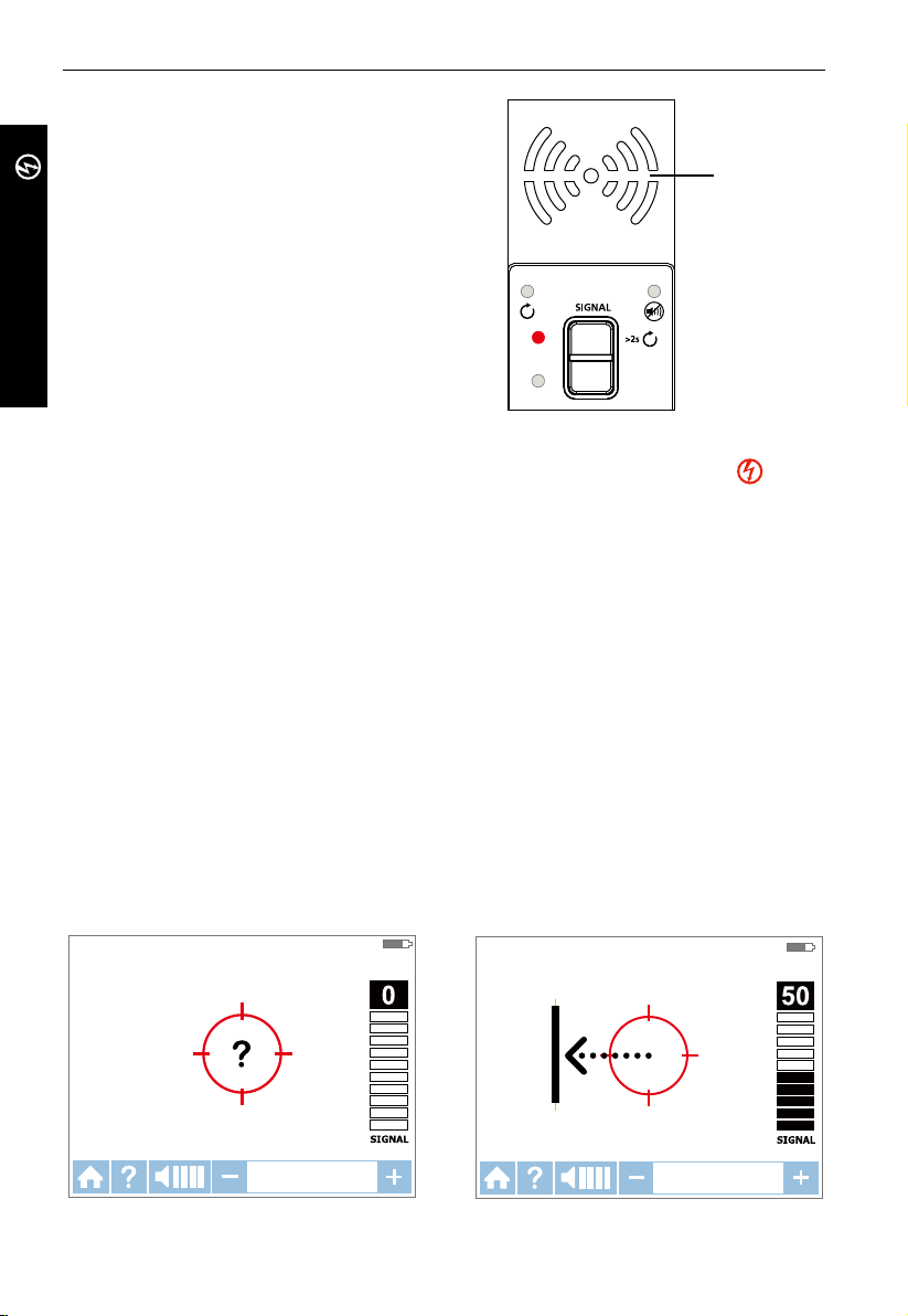
3. APPLICATIONS PRINCIPALES - SMART SENSORTM (Sous tension)
AT-8000-T
TRANSMITTER
Remarque: Le mode de précision de signal FAIBLE peut
être utilisé pour limiter le niveau de signal généré par
le transmetteur afin de repérer plus précisément la
localisation du fil. Un niveau de signal plus faible réduit
le couplage à des fils et à des objets métalliques situés
à proximité et permet d'éviter les lectures erronées
dues aux signaux fantômes. Un signal plus faible
TM
permet également d'empêcher la sursaturation du
récepteur avec un signal élevé couvrant une plage trop
grande. La fonction mode FAIBLE est seulement utilisée
pour les applications de traçage de fils les plus précises
et exigeantes.
HI
SMART SENSOR
LO
Figure 3.1c: Indicateur du transmetteur
affichant le signal en mode ÉLEVÉ
Utilisation du récepteur AT-8000-R en mode SMART SENSORTM sous tension
Le Smart SensorTM facilite le traçage de fil en indiquant la direction et la position du fil et constitue la
méthode recommandée pour tracer des fils sous tension.
Remarque: Le Smart Sensor
d'utiliser le capteur de pointe à la place.
TM
ne fonctionne pas sur les circuits hors tension ; il est préférable
Utiliser le récepteur AT-8000-R
1. Appuyez sur le bouton d'alimentation pour allumer le récepteur ; le chargement de l'écran d'accueil
peut prendre jusqu'à 30 secondes.
2. Sélectionnez le mode SMART SENSOR
jaune ENTRÉE.
3. Tenez le récepteur avec le Capteur intelligent
rouge clignote à l’écran, aucun signal n’est détecté ou le signal n’est pas suffisant pour afficher la
direction. (Figure 3.1d). Approchez le Smart Sensor
détecté et que vous visualisiez une flèche directionnelle. Si aucun signal n'est détecté, augmentez la
sensibilité à l'aide du bouton « + » du récepteur.*
4. Déplacez le récepteur dans la direction indiquée par la flèche à l'écran (Figure 3.1e).
5. Un symbole de cible verte indique que le récepteur est directement au-dessus du fil (Figure 3.1f). Si
le récepteur ne détecte pas le fil, diminuez la sensibilité à l'aide de la touche « - » sur le clavier ou
réglez le transmetteur pour qu'il transmette à un niveau FAIBLE pour un traçage de précision.
6. Appuyez sur ENTRÉE une fois terminé pour retourner à l'écran d'accueil.
*Remarque: Pour de meilleurs résultats, maintenez le récepteur à au moins 3 pieds (90 cm) du
transmetteur et de ses câbles d'essai afin de réduire les interférences du signal et d'améliorer
les résultats du traçage de fil. Sélectionnez la plage « Longue » du Smart Sensor
Paramètres en cas de fonctionnement avec des fils d'une profondeur supérieure à 90 cm.
CAPTEUR INTELLIGENT SOUS TENSION
TM
à l'aide des flèches directionnelles et appuyez sur le bouton
TM
orienté vers la zone cible. Si un «?» dans une cible
TM
de la zone cible jusqu'à ce que le signal soit
CAPTEUR INTELLIGENT SOUS TENSION
CLIGNOTANT
TM
dans le menu
Figure 3.1d:
Aucun signal détecté
14
Figure 3.1e:
Le fil est à gauche

3. APPLICATIONS PRINCIPALES - CAPTEUR DE POINTE (Sous tension)
-
-
CAPTEUR INTELLIGENT SOUS TENSION
Figure 3.1f : Le récepteur a détecté le fil
Utilisation du récepteur AT-8000-R en mode CAPTEUR DE POINTE sous tension
Le mode CAPTEUR DE POINTE est utilisé pour les applications suivantes : repérer un fil
dans un faisceau, tracer dans des coins et des espaces confinés tels que des boîtiers de
raccordement ou à l'intérieur de coffrets.
1. Appuyez sur le bouton d'alimentation pour allumer le récepteur ; le chargement de
l'écran d'accueil peut prendre jusqu'à 30 secondes.
2. Sélectionnez le mode CAPTEUR DE POINTE sous tension à l'aide des flèches
directionnelles et appuyez sur le bouton jaune ENTRÉE.
3. Tenez le récepteur avec le capteur de pointe orienté vers la zone cible.
4. Balayez la zone cible avec le capteur de pointe pour trouver le niveau de signal le plus
élevé (Figure 3.1g). En traçant, réglez de temps en temps la sensibilité pour maintenir
l'intensité du signal autour de 75. Augmentez ou diminuez la sensibilité en appuyant
sur + ou – sur le clavier numérique. Si le signal est trop fort pour une localisation
précise, passez le transmetteur en mode FAIBLE.
5. Positionnement du récepteur : Pour de meilleurs résultats, alignez la rainure sur le
capteur de pointe avec la direction du fil. Le signal peut être perdu si elle n'est pas
alignée correctement (Figure 3.1h).
6. Pour vérifier la direction du fil, tournez de temps en temps le récepteur de 90 degrés.
L'intensité du signal sera la plus élevée si le fil est aligné avec la rainure du capteur de
pointe (Figure 3.1i).
7. Appuyez sur ENTRÉE une fois terminé pour retourner à l'écran d'accueil.
Remarque: Pour de meilleurs résultats, maintenez le récepteur à au moins 3 pieds (1 m)
du transmetteur et de ses câbles d'essai afin de réduire les interférences du signal et
d'améliorer les résultats du traçage de fil.
POINTE DU CAPTEUR SOUS TENSION
CAPTEUR DE POINTE
75
SIGNAL
30-600V AC/DC
40-400 HZ
Figure 3.1g : Écran du récepteur indiquant le signal
détecté en mode CAPTEUR DE POINTE sous tension
15

3. APPLICATIONS PRINCIPALES - CAPTEUR DE POINTE (Sous tension)
AT-8000-T
TRANSMITTER
Aligner
Rainure de
pointe
CAPTEUR DE POINTE
Aligner le capteur de pointe avec le fil
3.2 Tracer des fils hors tension
Connexion des câbles d’essaidu transmetteur
1. Connectez les câbles d’essai vert et rouge au
transmetteur (la polarité n’a pas d’importance).
2. Avec les câbles d’essai fournis, connectez le fil vert à
une terre séparée (structure métallique de bâtiment,
canalisation d’eau métallique ou fil de terre sur un
circuit séparé) (Figure 3.2a).
3. Raccordez le câble d’essai rouge au fil tracé. Pour les
prises électriques, assurez-vous de raccorder le câble
d’essai au fil de ligne (alimenté hors tension). Pour
les systèmes hors tension, le signal sera transmis à
travers toutes les branches du circuit.
Figure 3.1h :
Figure 3.1i :
Tourner le récepteur pour
l'aligner avec le fil
AT-8000-T
Figure 3.2a : Raccordement approprié
Configurer le transmetteur AT-8000-T :
1. Appuyez sur le bouton d’alimentation pour l’allumer le transmetteur.
2. Vérifiez que les câbles d’essai sont correctement
raccordés ; l’indicateur LED rouge de statut de tension
doit être éteint pour les circuits hors tension avec une
tension inférieure à 30 V CA/CC.
Remarque: Assurez-vous d’utiliser le raccordement
séparé à la terre comme décrit ci-dessus.
3. Sélectionnez le mode de signal ÉLEVÉ en appuyant sur
HI pour la plupart des applications. Le transmetteur
apparaît comme indiqué dans la figure 3.2b.
L’affichage LED commence rapidement à clignoter.
Remarque: Le mode de précision de signal FAIBLE peut
être utilisé pour limiter le niveau de signal généré par
le transmetteur afin de repérer plus précisément la
localisation du fil. Un niveau de signal plus faible réduit
le couplage à des fils et à des objets métalliques situés à
proximité et permet d’éviter les lectures erronées dues aux
signaux fantômes. Un signal plus faible permet également
d’empêcher la sursaturation du récepteur avec un signal
élevé couvrant une plage trop grande. La fonction mode
FAIBLE est seulement utilisée pour les applications de
Figure 3.2b: Indicateur du
transmetteur affichant le signal
traçage de fils les plus précises et exigeantes.
16
avec mise à la terre séparée
CLIGNOTANT
HI
LO
en mode ÉLEVÉ

3. APPLICATIONS PRINCIPALES - CAPTEUR DE POINTE (HoRs tension)
-
-
Utilisation du récepteur AT-8000-R en mode CAPTEUR DE POINTE hors tension
CAPTEUR DE POINTE
Le mode CAPTEUR DE POINTE hors tension est utilisé pour le traçage général de fils, repérer
des fils dans des faisceaux, tracer dans des coins étroits et des espaces confinés tels que des
boîtiers de raccordement ou à l'intérieur de coffrets.
1. Appuyez sur le bouton d'alimentation pour allumer le récepteur ; le chargement de
l'écran d'accueil peut prendre jusqu'à 30 secondes.
2. Sélectionnez le mode CAPTEUR DE POINTE hors tension à l'aide des flèches
directionnelles et appuyez sur le bouton jaune ENTRÉE.
3. Tenez le récepteur avec le capteur de pointe orienté vers la zone cible.*
4. Balayez la zone cible avec le capteur de pointe pour trouver le niveau de signal le plus
élevé (Figure 3.2c). En traçant, réglez de temps en temps la sensibilité pour maintenir
l'intensité du signal autour de 75. Augmentez ou diminuez la sensibilité en appuyant
sur + ou – sur le clavier numérique. Si le signal est trop fort pour une localisation
précise, passez le transmetteur en mode FAIBLE.
5. Appuyez sur ENTRÉE une fois terminé pour retourner à l'écran d'accueil.
POINTE DU CAPTEUR HORS TENSION
0-30V AC/DC
75
SIGNAL
CAPTEUR DE POINTE
Figure 3.2c: Récepteur indiquant le signal détecté en mode CAPTEUR DE POINTE hors tension
*Remarque: Pour de meilleurs résultats, maintenez le récepteur à au moins 3 pieds (1 m)
du transmetteur et de ses câbles d'essai afin de réduire les interférences du signal et
d'améliorer les résultats du traçage de fil.
Le mode hors tension utilise une antenne différente dans le capteur de pointe par rapport
au mode sous tension. L'alignement spécifique de la rainure du capteur de pointe sur le fil
n'est pas nécessaire. Les résultats du traçage de fils hors tension sont uniquement basés sur
la proximité du capteur de pointe par rapport au fil.
3.3 Identifier les disjoncteurs et les fusibles
Le mode Disjoncteur ajuste automatiquement la sensibilité du récepteur. Ainsi, le récepteur
localise et indique un seul disjoncteur/fusible correct. Cette amélioration permet de
supprimer l'analyse de l'intensité du signal du processus d'identification du disjoncteur/
fusible, typique sur les traceurs de fils moins avancés.
Remarque: Pour localiser un disjoncteur/fusible, un raccordement direct simplifié aux fils
alimenté et neutre peut être utilisé car ces fils sont séparés au niveau du panneau du
disjoncteur/fusible. Il n'y a aucun risque d'effet d'annulation du signal si les fils sont au
moins à quelques centimètres l'un de l'autre. Cependant, le raccordement séparé à la terre
(Figure 3.3b) doit être utilisé pour de meilleurs résultats, en particulier si les fils doivent être
tracés en plus de l'identification du disjoncteur.
Le raccordement direct simplifié au fil alimenté et neutre NE déclenche PAS le circuit GFCI.
17

3. APPLICATIONS PRINCIPALES - CAPTEUR DE POINTE (HoRs tension)
AT-8000-T
CAPTEUR DE POINTE
Figure 3.3a : Raccordement direct simplifié
Figure 3.3b : Raccordement avec mise à la
AT-8000-T
terre séparée (Préférable)
Connexion du transmetteur - Systèmes sous tension et hors tension
La connexion du transmetteur est la même pour la localisation d'un disjoncteur/fusible sous tension
et hors tension.
Connexion des câbles d'essai
1. Raccordez le transmetteur à l'aide du raccordement direct simplifié ou du raccordement avec
mise à la terre séparée.
2. Si la méthode de raccordement direct simplifié est utilisée, raccordez les câbles d'essai
directement aux fils alimenté et neutre. Pendant la localisation d'un disjoncteur, les fils ne sont
pas traçables car les signaux s'annulent mutuellement.
3. Pour un raccordement avec mise à la terre séparée, raccordez d’abord le câble vert à une terre
séparée, telle qu’une structure métallique de bâtiment, une canalisation d’eau métallique ou un
fil de terre sur un circuit séparé.
4. Raccordez le câble rouge au fil alimenté sous tension sur le côté charge du système. Le signal
sera UNIQUEMENT transmis entre la prise à laquelle le transmetteur est raccordé et la source
d’alimentation.
AT-8000-T
Configurer le transmetteur AT-8000-T :
1. Appuyez sur le bouton d’alimentation pour l’allumer le transmetteur.
2. Vérifiez que les câbles d'essai sont correctement raccordés. Le voyant LED rouge de statut de la
tension s'allume pour les circuits sous tension avec une tension supérieure à 30V CA/CC. Si le
circuit est hors tension, le voyant est éteint.
3. Sélectionnez le mode de signal ÉLEVÉ pour la localisation d'un disjoncteur/fusible.
18

3. APPLICATIONS PRINCIPALES - DISJONCTEURS (Sous tension et hors
-
tension)
Localisation d'un disjoncteur/fusible sous tension et hors tension
DISJONCTEURS
Vue d'ensemble du processus du récepteur
Le traçage des disjoncteurs/fusibles est un processus en deux étapes :
1
BALAYAGE - Balaye chaque disjoncteur/fusible pendant une seconde. Le récepteur
2
LOCALISATION - Le récepteur indique le disjoncteur/fusible avec le signal enregistré le
Utiliser le récepteur AT-8000-R
1. Appuyez sur le bouton d'alimentation pour allumer le récepteur ; le chargement de
l'écran d'accueil peut prendre jusqu'à 30 secondes.
2. Sélectionnez le mode DISJONCTEURS sous tension ou le mode DISJONCTEURS hors
tension à l'aide des flèches directionnelles et appuyez sur le bouton jaune ENTRÉE.
Étape 1 - 1 BALAYAGE
1. L'appareil démarre automatiquement en mode
2. Balayez chaque disjoncteur/fusible pendant une seconde en le touchant avec le capteur
de pointe. Assurez-vous que la rainure du capteur de pointe est parallèle à la longueur
du disjoncteur/fusible (Figure 3.3e).
3. Pour assurer une durée suffisante entre les balayages, attendez la flèche verte animée
et l'alerte sonore (2 bips) avant de passer au disjoncteur/fusible suivant.
4. Balayez tous les disjoncteurs/fusibles, l'ordre de balayage n'a pas d'importance. Vous
pouvez balayer chaque disjoncteur/fusible plusieurs fois. Le récepteur enregistre le
signal détecté le plus élevé.
Conseil d'utilisation : Pour les meilleurs résultats possibles, essayez de balayer à la sortie du
disjoncteur/fusible.
&
enregistre les niveaux du signal de traçage.
plus fort.
1
BALAYAGE (Figure 3.3c).
DISJONCTEURS &
Remarque importante: La différence de conception, de hauteur et de structure de contact
interne des disjoncteurs/fusibles peut affecter la précision de l'identification du disjoncteur/
fusible. Pour obtenir les résultats les plus fiables, retirez le couvercle du panneau des
disjoncteurs/fusibles et effectuez un balayage sur les fils au lieu des disjoncteurs/fusibles.
Balayez toujours les disjoncteurs/fusibles avec la même position et le même alignement du
Capteur de pointe. Une variation peut entraîner des résultats incorrects.
DIJSONCTEURS SOUS TENSION
BALAYER
LOCALISER
VÉRIFICATION DE CHAQUE DISJONCTEUR/FUSIBLE
Figure 3.3c : Mode BALAYAGE –Balayage
de disjoncteurs/fusibles
Figure 3.3e : Alignement correct du capteur
de pointe par rapport au disjoncteur
19

3. APPLICATIONS PRINCIPALES - DISJONCTEURS (Sous tension)
-
Étape 2 - 2 LOCALISATION
1. Sélectionnez le mode LOCALISATION à l'aide
des flèches directionnelles et appuyez sur le
bouton jaune ENTRÉE (Figure 3.3d).
2. Rebalayez chaque disjoncteur/fusible en les
touchant avec le capteur de pointe pendant
une seconde. La flèche rouge animée indique
l'avancement du balayage. Assurez-vous que la
rainure du capteur de pointe est parallèle à la
longueur du disjoncteur/fusible (Figure 3.3e).
Conseil d'utilisation : Tenez le récepteur dans la
DIJSONCTEURS SOUS TENSION
BALAYER
LOCALISER
NOUVELLE VÉRIFICATION POUR LOCALISER LE
DISJONCTEUR/FUSIBLE
-
même position que lors de l'étape de balayage.
3. Rebalayez tous les disjoncteurs/fusibles jusqu’à
MODE NCV
ce qu’une flèche verte fixe et une alerte sonore
indiquent que le disjoncteur/fusible correct a
été trouvé (Figure 3.3f).
4. Appuyez sur ENTRÉE une fois terminé pour retourner à l'écran d'accueil.
Figure 3.3d : Mode LOCALISATION –
Recherche de disjoncteurs/fusibles corrects
Conseil d'utilisation : La précision des résultats de l'identification du disjoncteur/fusible
peut être vérifiée en passant le récepteur au mode CAPTEUR DE POINTE sous tension ou
hors tension et en vérifiant que le niveau du signal du disjoncteur identifié par le récepteur
est le plus élevé parmi tous les disjoncteurs/fusibles.
DIJSONCTEURS SOUS TENSION
BALAYER
LOCALISER
DISJONCTEUR/FUSIBLE DÉTECTÉ
Figure 3.3f : Mode LOCALISATION : Disjoncteur/fusible identifié
3.4 Mode NCV
Le mode NCV (Non-Contact Voltage : Tension sans contact) est utilisé pour vérifier qu'un fil
est sous tension. Cette méthode ne nécessite pas l'utilisation du transmetteur. Le récepteur
détecte et trace un câble sous tension si la tension est entre 90 V et 600 V CA et entre 40 Hz
et 400 Hz. Aucun courant n'est nécessaire.
Remarque: Pour votre sécurité, avant de travailler sur des fils, vérifiez toujours qu'ils sont
hors tension avec un testeur de tension supplémentaire.
� L'indication de tension en mode tension sans contact n'est pas suffisante pour
assurer la sécurité. Cette fonction ne convient pas pour vérifier l'absence de tension. Ceci
nécessite toujours un test de tension à deux pôles.
Fonctionnement en mode NCV
1. Appuyez sur le bouton d'alimentation pour allumer le récepteur ; le chargement de l'écran
d'accueil peut prendre jusqu'à 30 secondes.
2. Appuyez sur le bouton NCV pour sélectionner le mode NCV - Tension sans contact.
3. Tenez le récepteur avec le capteur de pointe contre le fil.
4. Pour un repérage précis du fil de ligne/phase par rapport au fil neutre, augmentez ou
diminuez la sensibilité en appuyant sur + ou – sur le clavier.
5. Appuyez sur ENTRÉE une fois terminé pour retourner à l'écran d'accueil.
20

4. APPLICATIONS SPÉCIALES
TENSION SANS CONTACT
Figure 3.4: Détection de tension en mode NCV à l'aide du capteur de pointe
4.1 Traçage de fils dans les circuits à protection DDFT
Connecter le transmetteur AT-8000-T aux circuits à protection DDFT.
Connecter le transmetteur à un circuit à protection DDFT sous tension avec une méthode de
mise à la terre séparée déclenche la protection DDFT. Utilisez les méthodes suivantes pour
travailler avec les circuits à protection DDFT (pour une prise à protection DDFT hors tension
non déclenchée, vous pouvez brancher les câbles d'essai directement sur les contacts de la
prise à l'aide du mode CAPTEUR DE POINTE hors tension)
Méthode 1 – Court-circuitez le système de circuits GFCI pour éviter de déclencher le DDFT :
(uniquement pour les prises à protection DDFT sous tension)
• Retirez la plaque murale de protection de la prise électrique.
• À l'aide de la pince crocodile fixez un câble d'essai rouge à la vis raccordant le fil
alimenté sous tension à la prise électrique.
• Raccordez le câble d'essai vert à l'aide de la méthode de mise à la terre séparée telle
que décrite dans le mode CAPTEUR DE POINTE sous tension.
• Effectuez le traçage comme décrit dans l'un des modes sous tension : SMART SENSOR
CAPTEUR DE POINTE ou DISJONCTEUR.
TM
,
Méthode 2 – N'utilisez PAS la mise à la terre séparée pour éviter de déclencher le DDFT :
(pour les prises et les disjoncteurs à protection DDFT)
• Raccordez les câbles d'essai du transmetteur aux fils Neutre et Alimenté.
• Effectuez le traçage comme décrit dans l'un des modes sous tension : SMART SENSOR
CAPTEUR DE POINTE ou DISJONCTEUR.
Remarque: Ce type de raccordement entraîne le couplage du signal et réduit l'intensité du
signal. Si le signal est trop faible ou non traçable, utilisez la Méthode 3.
Méthode 3 : Mettez le circuit hors tension :
(pour les disjoncteurs à protection DDFT)
• Mettez le circuit hors tension.
• Raccordez directement un transmetteur au fil comme décrit dans le mode CAPTEUR DE
POINTE hors tension
• Effectuez le traçage comme décrit dans le mode hors tension souhaité (CAPTEUR DE
POINTE pour traçage de fil ou DISJONCTEUR pour identification de disjoncteur).
21
TM
,

4. APPLICATIONS SPÉCIALES
4.2 Trouver les sectionnements/ouvertures
Il est possible de repérer la localisation exacte de l'endroit où un fil est sectionné, même si le
fil se situe derrière des murs, des sols ou des plafonds.
1. Assurez-vous que le fil est hors tension.
2. Utilisez les étapes décrites dans la section 3.2 pour raccorder le transmetteur et
effectuez le traçage avec le récepteur réglé en mode CAPTEUR DE POINTE hors tension.
3. Pour de meilleurs résultats, raccordez à la terre tous les fils hors tension qui passent en
parallèle avec le câble d'essai noir. (Figure 4.2).
Le signal de traçage généré par le transmetteur est conduit le long du fil tant qu'il existe
une continuité dans le conducteur métallique. Pour trouver un défaut, tracez le fil jusqu'à
ce que le signal s'arrête. Pour vérifier la localisation du défaut, déplacez le transmetteur à
l'autre extrémité du fil et répétez le traçage depuis l'extrémité opposée. Si le signal s'arrête
exactement au même endroit, le défaut a été localisé.
Remarque: Si la localisation du défaut est introuvable, le résultat peut être une rupture de
résistance élevée (circuit partiellement ouvert). Un tel sectionnement empêche des courants
plus élevés de transiter mais conduit le signal de traçage par le sectionnement. De tels
défauts ne sont pas détectés jusqu'à ce que le fil soit complètement ouvert.
CAT IV 600V AC
TIP
SENSOR
Figure 4.2: Localiser l'emplacement du défaut
4.3 Trouver des courts-circuits
Les fils en court-circuit entraînent le déclenchement d'un disjoncteur/fusible. Pour corriger
ce problème, débranchez les fils et assurez-vous que les extrémités des fils des deux côtés du
câble sont isolées l'une de l'autre et des autres fils ou charges et qu'ils sont hors tension.
1. Raccordez le transmetteur avec les câbles d'essai au circuit comme indiqué dans la
Figure 4.3.
2. Mettez le transmetteur en mode Boucle en appuyant sur le bouton ÉLEVÉ pendant 2
secondes. Vérifiez que la LED Boucle est allumée.
3. Réglez le récepteur en mode CAPTEUR DE POINTE sous tension (le transmetteur génère
un signal de traçage basse tension sûr) et effectuez le traçage.
Commencez le traçage du câble jusqu'à ce que le signal s'arrête. Pour vérifier la localisation
du défaut, déplacez le transmetteur à l'autre extrémité du fil et répétez le traçage depuis
l'extrémité opposée. Si le signal s'arrête exactement au même endroit, le défaut a été localisé.
Remarque: Cette méthode est affectée d'un effet d'annulation du signal. Prévoyez un signal
relativement faible.
22

4. APPLICATIONS SPÉCIALES
CAT IV 600V AC
TIP
SENSOR
Figure 4.3: Trouver un court-circuit
4.4 Tracer des fils dans un conduit métallique : Méthode avec boîtier de jonction
Le récepteur AT-8000-R ne peut pas capter le signal provenant du fil à travers le conduit
métallique. Le conduit métallique masque complètement le signal de traçage.
Remarque: Le récepteur peut détecter des fils dans un conduit non métallique. Pour ces
applications, suivez les directives générales de traçage.
Afin de tracer des fils dans un conduit :
1. Utilisez le mode CAPTEUR DE POINTE sous tension ou hors tension comme décrit dans
les sections 3.1 et 3.2.
2. Ouvrez les boîtiers de raccordement et utilisez le capteur de pointe du récepteur pour
détecter quel fil du boîtier de raccordement transmet le signal.
3. Passez de boîtier de raccordement en boîtier de raccordement pour suivre le
cheminement du fil.
Remarque: Appliquer le signal directement au conduit envoie le signal dans toutes les
branches du conduit, rendant impossible le traçage du cheminement d'un conduit particulier.
4.5 Tracer des tuyaux et des conduits non métalliques
L'AT-8000 peut tracer indirectement des conduits et des tuyaux en plastique à l'aide des
étapes suivantes :
1. Insérez le ruban de tirage conducteur ou le fil à l'intérieur du conduit.
2. Raccordez le câble d'essai rouge du transmetteur au ruban de tirage et le fil de terre
vert à une terre séparée comme décrit dans la section 3.2.
3. Réglez le récepteur sur le mode CAPTEUR DE POINTE hors tension pour tracer le conduit.
4. Le récepteur capte le signal conduit par le ruban de tirage ou le fil à travers le conduit.
23

4. APPLICATIONS SPÉCIALES
4.6 Tracer des fils blindés
Les fils blindés empêchent le récepteur de détecter un signal de traçage en suivant les instructions
d'utilisation standard. Pour tracer efficacement un fil blindé, suivez ces procédures.
Si le fil blindé est mis à la terre à l'extrémité:
1. Configurez le transmetteur en mode Boucle en appuyant sur le bouton ÉLEVÉ pendant deux
secondes. Vérifiez que la LED Boucle est allumée.
2. Débranchez la mise à la terre près de l'extrémité du fil blindé et raccordez le blindage à l'une
des bornes du transmetteur (la polarité n'a pas d'importance) avec un câble d'essai.
3. Raccordez la deuxième sortie du transmetteur à une mise à la terre séparée.
4. Réglez le récepteur sur le mode CAPTEUR DE POINTE hors tension pour tracer le blindage
comme décrit dans la section 3.2.
CAT IV 600V AC
TIP
SENSOR
Figure 4.6a : Tracer un fil blindé
Si le fil blindé est débranché de la terre à l'extrémité:
1. Configurez le transmetteur en mode Traçage de fils (voir section 3.2).
2. Débranchez la mise à la terre près de l'extrémité du fil blindé et raccordez le blindage à l'une
des bornes du transmetteur (la polarité n'a pas d'importance) avec un câble d'essai.
3. Raccordez la deuxième sortie du transmetteur à une mise à la terre séparée.
4. Réglez le récepteur sur le mode traçage de fil pour tracer le blindage comme décrit dans la
section 3.2.
CAT IV 600V AC
TIP
SENSOR
Figure 4.6b: Tracer un fil blindé déconnecté de la terre à l'extrémité
24

4. APPLICATIONS SPÉCIALES
4.7 Tracer des fils souterrains
L'AT-8000 peut tracer des fils souterrains, de la même manière il peut localiser des fils
derrière les murs ou sous les sols.
Effectuez le traçage tel que décrit dans le mode SMART SENSORTM sous tension ou les modes
CAPTEUR DE POINTE sous tension / hors tension.
Vous pouvez utiliser une fixation de fiche alimentée pour rendre le traçage plus
ergonomique et pratique.
CAT IV 600V AC
TIP
SENSOR
Figure 4.7: Tracer des fils souterrains
4.8 Tracer des fils à basse tension et des câbles de données
L'AT-8000 peut tracer des câbles de données, audio et de thermostats (pour tracer des câbles
de données blindés, consultez la section 4.6).
Tracer les câbles de données, audio et de thermostats :
1. Raccordez le transmetteur à l'aide de la méthode de mise à la terre séparée décrite
dans la section 3.2.
2. Réglez le récepteur sur le mode CAPTEUR DE POINTE hors tension et tracez le fil.
25

4. APPLICATIONS SPÉCIALES
4.9 Trier des fils en faisceau
Identifier un fil spécifique dans un faisceau :
1. Raccordez le transmetteur à l'aide du mode CAPTEUR DE POINTE sous tension ou hors
tension. En cas de connexion à un fil sous tension, assurez-vous que le transmetteur est
raccordé sur le côté charge.
2. Sélectionnez respectivement le mode CAPTEUR DE POINTE sous tension ou hors tension
sur le récepteur. Dans la mesure du possible, tirez un fil parmi les autres fils du faisceau
et touchez-le avec le Capteur de pointe. Le signal le plus fort indique le bon fil dans le
faisceau.
Remarque: Dans certains cas spécifiques, il peut être nécessaire de raccorder tous les fils
non utilisés côté Transmetteur à la terre.
CAT IV 600V AC
TIP
SENSOR
4.9a : Identifier un fil sous tension dans un faisceau
4.9b : Identifier un fil hors tension dans un faisceau
26
CAT IV 600V AC
TIP
SENSOR

4. APPLICATIONS SPÉCIALES
4.10 Situer un circuit à l'aide du raccordement de câbles d'essai
Situer un circuit ne peut être effectué que sur un circuit hors tension en utilisant le
raccordement des câbles d'essai.
1. Passez le disjoncteur/fusible en position ARRÊT.
2. Configurez le transmetteur et le récepteur pour le traçage de fil hors tension comme
décrit dans la section 3.2.
3. Balayez les plaques avant des prises et des fils vers les charges au capteur de pointe du
récepteur.
4. Tous les fils, prises et charges présentant un signal élevé indiqué par le récepteur sont
raccordés à ce disjoncteur/fusible.
AT-8000-T
Figure 4.10: Situer un circuit
4.11 Tracer des disjoncteurs/fusibles sur des systèmes avec des variateurs d'éclairage
Les variateurs d'éclairage peuvent produire une quantité significative de «bruit» électrique,
composé de signaux multifréquences. Dans certaines situations rares, le récepteur peut
interpréter à tort ce bruit, souvent appelé signal «fantôme», comme un signal généré par
le transmetteur. Par conséquent, le récepteur peut fournir des mesures incorrectes. Lors de
la localisation de disjoncteurs ou de fusibles sur des systèmes avec des variateurs d'éclairage,
le variateur doit être désactivé (l'interrupteur d'éclairage est éteint). Cela empêche le
récepteur d'indiquer un disjoncteur/fusible erroné.
27

4. APPLICATIONS SPÉCIALES
AT-8000-T
TRANSMITTER
4.12 Pince de signal - Circuits à boucle fermée
Circuits à boucle fermée, hors tension et à basse impédance
L'accessoire pince est utilisé pour les applications où aucun accès à un conducteur dénudé
n'existe pour raccorder les câbles d'essai. Quand la pince est raccordée au transmetteur,
elle permet au transmetteur d'induire un signal au fil sous tension ou hors tension à travers
l'isolation. Les applications courantes de la pince de signal comprennent le traçage de
conduits ou de blindages mis à la terre aux deux extrémités. Pour les câbles de signal et
les fils ou les charges hors tension, mettez temporairement le circuit à la terre aux deux
extrémités pour effectuer le traçage.
Raccordement de la pince de signal
1. Raccordez les câbles d'essai du CT-400 aux bornes du transmetteur (la polarité n'est pas
importante).
2. Fixez la pince de signal CT-400 autour du conducteur. Pour augmenter l'intensité du
signal, enroulez quelques tours du fil conducteur autour de la pince si possible.
Figure 4.12a : Raccordement de la pince de signal
Configurer le transmetteur AT-8000-T :
1. Appuyez sur le bouton d’alimentation pour l’allumer
le transmetteur. L'indicateur LED rouge de statut de
tension doit être ÉTEINT quand la pince est raccordée
et en travaillant avec des systèmes sous tension ou hors
tension.
2. Appuyez sur le mode de signal ÉLEVÉ et maintenez le
bouton enfoncé pendant > 2 secondes pour sélectionner
le mode Boucle sur le transmetteur. Ce mode pince
(mode boucle) génère un signal amplifié de 6 kHz afin
de procurer des résultats de traçage supérieurs.
28
AT-8000-T
HI
LO
Figure 4.12b: Indicateur du
transmetteur affichant le
signal en mode Boucle

4. APPLICATIONS SPÉCIALES
Utiliser le récepteur AT-8000-R
1. Appuyez sur le bouton d'alimentation pour allumer le récepteur ; le chargement de
l'écran d'accueil peut prendre jusqu'à 30 secondes.
2. Sélectionnez le mode CAPTEUR DE POINTE sous tension à l'aide des flèches
directionnelles et appuyez sur le bouton jaune ENTRÉE.
3. Tenez le récepteur avec le capteur de pointe orienté vers la zone cible.
4. Balayez la zone cible avec le capteur de pointe pour trouver le niveau de signal le plus
élevé. En traçant, réglez de temps en temps la sensibilité pour maintenir l'intensité du
signal autour de 75. Augmentez ou diminuez la sensibilité en appuyant sur + ou – sur le
clavier numérique.
5. Positionnement du récepteur : Pour de meilleurs résultats, alignez la rainure sur le
Capteur de pointe avec la direction du fil comme indiqué. Le signal peut être perdu si
elle n'est pas alignée correctement.
6. Pour vérifier la direction du fil, tournez de temps en temps le récepteur de 90 degrés.
L'intensité du signal sera la plus élevée si le fil est aligné avec la rainure du capteur de
pointe.
7. Appuyez sur ENTRÉE une fois terminé pour retourner à l'écran d'accueil.
Aligner
Rainure de
pointe
Figure 4.12c : Aligner le capteur de
*Remarque: Pour de meilleurs résultats, maintenez le récepteur à au moins 3 pieds
(90 cm) du transmetteur, de la pince de signal et de ses câbles d'essai afin de réduire les
interférences du signal et d'améliorer les résultats du traçage de fil.
pointe avec le fil
Figure 4.12d : Tourner le récepteur
pour l'aligner avec le fil
29

4. APPLICATIONS SPÉCIALES
4.13 Pince de signal - Situer les circuits
L'accessoire pince peut être utilisé pour situer des charges sur des disjoncteurs/fusibles
spécifiques dans des systèmes sous tension et hors tension. Il n'y a pas besoin de couper
l'alimentation électrique.
1. Fixez le CT-400 autour du fil sur le panneau du disjoncteur/fusible.
2. Configurez le transmetteur et le récepteur comme décrit dans la section précédente
4.12.
3. Balayez les plaques avant des prises et des fils raccordant les charges avec le capteur
de POINTE du récepteur. En mode Boucle, vous devez régler le récepteur en mode
CAPTEUR DE POINTE hors tension.
4. Tous les fils, prises et charges présentant un signal élevé indiqué par le récepteur sont
raccordés à ce disjoncteur/fusible.
AT-8000-T
Figure 4.13: Localisation des charges avec la pince de signal
30

5. MAINTENANCE
5.1 Remplacement des piles
Changer les piles du transmetteur
Le compartiment des piles à l'arrière du transmetteur est conçu pour faciliter le changement
de piles par l'utilisateur. Une vis est ajoutée pour retenir la pile en cas de chute de l'appareil.
Huit (8) piles alcalines AA ou NiMH rechargeables peuvent être utilisées. Les piles NiMH
doivent être retirées pour être chargées.
Remarque: Les piles ne sont pas préinstallées dans le transmetteur.
1. Assurez-vous que le transmetteur est éteint et déconnecté du circuit.
2. Utilisez un tournevis cruciforme pour dévisser les vis du compartiment des piles.
3. Retirez le couvercle des piles (Figure 5.1a).
4. Installez les piles.
5. Remettez le couvercle des piles et fixez-le avec les vis.
Vis
Cache du
compartiment
8 x piles AA
à piles
Figure 5.1a : Changer les piles du transmetteur
31

5. MAINTENANCE
Sélection manuelle du type de piles du transmetteur
Le type de piles utilisées - alcalines ou NiMH rechargeables - peut être reconnu
automatiquement lors de la mise sous tension de l'appareil ou défini manuellement par
l'utilisateur.
Régler le type de piles sur alcalines:
1. Assurez-vous que le transmetteur est éteint.
2. Appuyez et maintenez le bouton VOLUME PLUS (+).
3. Tout en appuyant sur le bouton Volume Plus, appuyez sur le bouton d'alimentation. Le
type de piles choisi sera Alcaline.
Régler le type de piles sur NiMH rechargeables:
1. Assurez-vous que le transmetteur est éteint.
2. Appuyez et maintenez le bouton VOLUME MOINS (-).
3. Tout en appuyant sur le bouton Volume Moins, appuyez sur le bouton d'alimentation.
Le type de piles choisi sera NiMH rechargeable.
Si le type de piles n'est pas défini manuellement, il sera reconnu automatiquement. La
reconnaissance automatique du type de piles absorbe plus de courant et peut manquer de
fiabilité si des piles non adaptées ou usagées sont utilisées. La reconnaissance automatique
des piles peut également manquer de fiabilité si les piles rechargeables n'ont pas été
chargées depuis plus d'un mois.
État des piles du transmetteur
Correspondant à 8piles AA de même type et connectées en série.
SEUIL DES PILES ALCALINES
L'appareil s'éteint si la tension est inférieure à 6,9V
Pile vide – LED ROUGE clignotante si la tension est > 7,3 V et < 9,4 V
0-10% - La LED ROUGE est allumée pour les tensions > 9,6 V et < 9,9 V
10-40% - Deux LED jaunes sont allumées pour les tensions > 10 V et < 10,8 V
40-75% - Trois LED vertes sont allumées pour les tensions > 10,9 V et < 12 V
> 75% - Quatre LED vertes sont allumées pour les tensions > 12 V
SEUIL DES PILES NiMH
L'appareil s'éteint si la tension est inférieure à 6,9V
Pile vide – LED ROUGE clignotante si la tension est > 7,1 V et < 7,3 V
0-10% - La LED ROUGE est allumée pour les tensions > 7,4 V et < 7,6 V
10-40% - Deux LED jaunes sont allumées pour les tensions > 7,7 V et < 8,5 V
40-75% - Trois LED vertes sont allumées pour les tensions > 8,6 V et < 9,7 V
> 75% - Quatre LED vertes sont allumées pour les tensions > 9,8 V
32

5. MAINTENANCE
Changer les piles du récepteur
Le compartiment des piles à l'arrière du récepteur est conçu pour faciliter le changement de
piles par l'utilisateur. Une vis est ajoutée pour retenir la pile en cas de chute de l'appareil.
Quatre (4) piles alcalines AA ou NiMH rechargeables peuvent être utilisées. Les piles NiMH
doivent être retirées pour être chargées.
Remarque: Les piles ne sont pas préinstallées dans le récepteur.
1. Assurez-vous que le récepteur est éteint.
2. Utilisez un tournevis en plate pour dévisser la vis imperdable.
3. Retirez le couvercle des piles (Figure 5.1b).
4. Installez les piles.
5. Remettez le couvercle des piles et fixez-le avec la vis fournie.
Vis
Cache du
compartiment
à piles
4 x piles AA
Figure 5.1b: Changer les piles du récepteur
33

5. MAINTENANCE
5.2 Remplacement du fusible
Remplacement du fusible du transmetteur
Avertissement : Pour éviter les chocs, les blessures ou les dommages au
�
transmetteur, débranchez les câbles d'essai avant d'ouvrir le boîtier.
1. Débranchez tous les câbles d'essai du transmetteur.
2. Assurez-vous que le transmetteur est éteint.
3. Utilisez un tournevis cruciforme pour dévisser les vis du support basculant.
4. Enlevez la trappe du compartiment des piles et retirez toutes les piles.
5. Utilisez un tournevis cruciforme pour dévisser les vis de fixation.
6. Retirez le couvercle arrière en le tirant vers le haut (Figure 5.2).
7. Retirez le fusible du porte-fusible.
8. Insérez le nouveau fusible (1,6A, 700V MAX, RAPIDE Ø 6X32mm) dans le portefusible.
9. Insérez le couvercle arrière, attachez-le bien avec les vis de fixation puis serrez avec un
tournevis cruciforme.
Fusible
Figure 5.2: Remplacement du fusible du transmetteur
34

6. SPÉCIFICATIONS
Caractéristiques AT-8000-R AT-8000-T CT-400
Catégorie de
mesure
Tension de
fonctionnement
Fréquence de
fonctionnement
Détection des
tensions
Indications de
signal
Temps de réponse Mode intelligent : 750 ms
Sortie de courant
du signal (type)
Tension du signal
en sortie (nominal)
Plage de détection
(en plein air)
CAT IV 600 V CAT IV 600 V CAT IV 600 V,
0 à 600V CA/CC 0 à 600V CA/CC 0 à 1000 V CA
Sous tension : 6,25 kHz
Hors tension : 32,768 kHz
Voir la détection NCV > 30 V CA/CC S/O
Affichage d'un histogramme
numérique et émission d'un
bip sonore
Capteur de pointe sous
tension: 300 ms
Capteur de pointe hors
tension: 750 ms
NCV : 500 ms
Contrôle de batterie : 5 s
S/O Circuit sous tension:
S/O Circuit hors tension:
Mode intelligent
Repérage :
Approximativement 1,97 po
(5 cm) de rayon (±2%)
Indication de la direction :
Jusqu'à 5 pi (152,4 cm) (±2%)
Capteur de pointe :
Sous tension
Repérage : Environ 1,97 po
(5 cm) (±1 %)
Détection : Jusqu'à 22 pi
(670,56 cm) (±1%)
Capteur de pointe :
Hors tension
Détection : Jusqu'à 14 pi
(426,72 cm) (±5%)
NCV (40-400 Hz)
Repérage : Environ 1,97 po
(5cm) de rayon (±5%)
Détection : Jusqu'à 4 pi
(121,92 cm) (±5%)
Sous tension/Boucle : 6,25 kHz
Hors tension : 32,768 kHz
LED et bip sonore S/O
Contrôle de la tension de
ligne: 1 s
Contrôle de la tension de la
pile: 5 s
Mode FORT: 60 mA RMS
Mode FAIBLE: 30 mA RMS
Circuit hors tension:
Mode FORT: 130 mA RMS
Mode FAIBLE: 40 mA RMS
Mode Boucle: 160 mA RMS
FAIBLE: 29 V RMS, 120V p-p
FORT: 33V RMS, 140V p-p
Modèle Boucle: 31V RMS,
120V p-p
S/O S/O
CAT II 1000 V
Mode Boucle:
6,25 kHz
Mode Élevé /
Faible: 32,768 kHz
Mesure du courant
CA: 45 Hz à 400 Hz
Instantané
1mA/A pour la
mesure de courant
CA avec un
multimètre
Circuit hors
tension:
2,4V RMS, 24V p-p
35

6. SPÉCIFICATIONS
Caractéristiques générales
Caractéristiques AT-8000-R AT-8000-T CT-400
Taille de l'écran 3,5 po (89 mm) LED S/O
Dimensions de l’écran
(L x H)
Résolution de
l'affichage
Type d'écran Écran LCD TFT LED S/O
Couleur d'affichage Oui LED du mode de
Durée de démarrage 30 s < 2 s S/O
Rétroéclairage Oui S/O S/O
Température de
fonctionnement
Humidité de
fonctionnement
Température et
humidité de stockage
Altitude de
fonctionnement
Protection contre les
tensions transitoires
Degré de pollution 2 2 2
Classification IP IP 52 IP 40 IP 40
Test de chute 3,28 pi (1 m) 3,28 pi (1 m) 3,28 pi (1 m)
Alimentation 4 x AA (alcalines ou NiMH
Consommation
électrique (type)
Durée de vie des piles
(normale)
Indicateur de piles
faibles
Fusible S/O 1,6 A, 700 V, à action
Taille maximale du
conducteur
Dimensions
(L x L x H)
(piles installées)
Poids
Certifications
2,76 x 2,07 po
(70 x 52 mm)
320 x 240 S/O S/O
-4 °F à 122 °F
(-20 °C à 50 °C)
45 % : -4 °F à < 50 °F
(-20 °C à < 10 °C)
95 % : 50 °F à < 86 °F
(10 °C à < 30 °C)
75 % : 86 °F à < 104 °F
(30 °C à < 40 °C)
45 % : 104 °F à < 122 °F
(40 °C à < 50 °C)
-4 °F à 158 °F
(-20 °C à 70 °C), ≤ 95% HR
0 à 6561 pieds (2000 m) 0 à 6561 pieds (2000 m) 0 à 6561 pieds (2000 m)
S/O 8,00 kV
rechargeables)
4 piles AA : 2 W Mode Fort/Faible: 70 mA
Environ 9 h Mode Fort/Faible: environ
Oui Oui S/O
S/O S/O 1,26 po (32 mm)
Environ 10,92 x 4,43 x 2,55 po
(278 x 113 x 65 mm)
Environ 1,20 lb (0,544 kg) Environ 1,25 lb (0,57 kg) Environ 0,25 lb (0,114 kg)
P
S/O S/O
fonctionnement: rouge
LED de statut de la pile:
verte, jaune, rouge
-4 °F à 122 °F
(-20 °C à 50 °C)
45 % : -4 °F à < 50 °F
(-20 °C à < 10 °C)
95 % : 50 °F à < 86 °F
(10 °C à < 30 °C)
75 % : 86 °F à < 104 °F
(30 °C à < 40 °C)
45 % : 104 °F à < 122 °F
(40 °C à < 50 °C)
-4 °F à 158 °F
(-20 °C à 70 °C), ≤ 95% HR
(surtension 1,2/50μS)
8 x AA (alcalines ou NiMH
rechargeables)
Mode Boucle avec pince:
90 mA
Consommation sans
transmission de signal:
10 mA
25 h
Mode Boucle: environ 18 h
rapideØ 6x32mm
Environ 7,2 x 3,66 x 1,91 po
(183 x 93 x 50 mm)
P
S/O
32 °F à 122 °F
(0 °C à 50 °C)
95 % : 50 °F à < 86 °F
75 % : 86 °F à < 104 °F
45 % : 104 °F à < 122 °F
-4 °F à 140 °F
(-20 °C à 60 °C), ≤ 95% HR
S/O
S/O
S/O
S/O
S/O
Environ 5,9 x 2,75 x 1,18 po
(150 x 70 x 30 mm)
(10 °C à < 30 °C)
(30 °C à < 40 °C)
(40 °C à < 50 °C)
P
36

6. SPÉCIFICATIONS
Spécifications des accessoires
Caractéristiques ADPTR-SCT TL-8000-INT
Catégorie de mesure CAT II CAT IV 600 V (câbles d'essai)
Tension et courant de
fonctionnement
Température de
fonctionnement
Humidité de fonctionnement ≤ 80% RH 95%: 50 °F à <86 °F (10 °C à <30 °C)
Température et humidité de
stockage
Altitude de fonctionnement 0 à 2000 m (6561 pieds) 0 à 6561 pieds (2000 m)
Degré de pollution 2 2
Classification IP IP 40 IP 20
Test de chute 3,28 pi (1 m) 3,28 pi (1 m)
Dimensions Environ 2,95 x 1,97 x 2,56 po
Poids Environ 0,125 lb (0,057 kg) Environ 0,88 lb (0,4 kg)
Certifications
102 à 253V CA, 4A max. 600 V, 10 A max. (fils rouge/noir)
32 °F à 104 °F (0 °C à 40 °C) 32 °F à 122 °F (0 °C à 50 °C)
32 °F à 104 °F / 0 °C à 40 °C,
≤ 80 % HR
(75 x 50 x 65 mm)
P
CAT IV 600 V (pinces crocodile)
CAT II 300 V (adaptateurs de sortie)
600V, 6 A max. (fil vert)
600V, 10A max. (pinces crocodile)
300 V, 10 A max. (adaptateurs de sortie)
75 % : 86 °F à <104 °F (30 °C à <40 °C)
45%: 104 °F à <122 °F (40 °C à <50 °C)
-4 °F à 140 °F (-20 °C à 60 °C), < 95% HR
Fils rouge/noir: 3,28 pi (1 m)
Fil vert: 22,97pi (7m)
Pinces crocodile:environ 3,74 x 1,77 x
0,94po (95 x 45 x 24 mm)
Adaptateurs de sortie : environ 2,83 x
0,71 x 0,71po (72 x 18 x 18 mm)
P
37


AT-8000
Rastreador de cable avanzado
AT-8020
AT-8030
Manual de usuario
Español
3/2020, 6012207 A
©2020 Amprobe.
Todos los derechos reservados.

Garantía limitada y limitación de responsabilidad
Su producto Amprobe no presentará defectos materiales ni de mano de obra durante un año a
partir de la fecha de compra, a menos que las leyes locales se pronuncien en otro sentido. Esta
garantía no cubre fusibles, pilas desechables o daños provocados por accidentes, negligencia, mal
uso, alteración, contaminación o condiciones anómalas de funcionamiento o manipulación. Los
revendedores no tienen autorización para ampliar ninguna otra garantía en nombre de Amprobe.
Para obtener servicio durante el período de garantía, devuelva el producto con una prueba de
compra a un Centro de servicio técnico autorizado de Amprobe o a un proveedor o distribuidor
de Amprobe. Consulte la sección Reparaciones para obtener más detalles. ESTA GARANTÍA
SERÁ SU ÚNICO MEDIO DE COMPENSACIÓN. POR EL PRESENTE DOCUMENTO, SE RECHAZAN EL
RESTO DE GARANTÍAS (YA SEAN EXPRESAS, IMPLÍCITAS O LEGALES), INCLUIDAS LAS GARANTÍAS
IMPLÍCITAS, DE ADECUACIÓN PARA UNA FINALIDAD DETERMINADA O DE COMERCIALIZACIÓN.
EL FABRICANTE NO ASUMIRÁ NINGUNA RESPONSABILIDAD POR NINGÚN DAÑO O PÉRDIDA
ESPECIAL, INDIRECTA, INCIDENTAL O CONSECUENTE, QUE SE HAYA PROVOCADO POR CUALQUIER
CAUSA O TEORÍA. Dado que algunos estados o países no permiten la exclusión o limitación de una
garantía implícita o de daños incidentales o consecuentes, es posible que esta limitación no se le
aplique a usted.
Reparación
Todas las herramientas de Amprobe devueltas para realizar una reparación cubierta o no por
la garantía, o para realizar tareas de calibración, deben estar acompañadas de lo siguiente:su
nombre, nombre de la compañía, dirección, número de teléfono y justificante de compra. Además,
incluya una breve descripción del problema o del servicio solicitado, así como los conductores de
comprobación con el medidor. El pago de la reparación o sustitución no cubierta por la garantía se
hará a través de un cheque, giro postal, tarjeta de crédito con fecha de caducidad o una orden de
compra pagadera a Amprobe.
Reparaciones y sustituciones cubiertas por la garantía: Todos los países
Lea la declaración de garantía y compruebe la pila antes de solicitar el servicio de reparación.
Durante el período de garantía, puede devolver cualquier herramienta de comprobación
defectuosa al distribuidor de Amprobe para que se la cambien por otra nueva o similar. Consulte
la sección "Where to Buy" (Lugares de compra) en amprobe.com para obtener una lista de los
distribuidores cercanos. Además, en Estados Unidos y Canadá, las unidades de reparación y
sustitución cubiertas por la garantía también se pueden enviar al Centro de servicio técnico de
Amprobe (consulte la dirección a continuación).
Reparaciones y sustituciones no cubiertas por la garantía: Estados Unidos y Canadá
Las reparaciones no cubiertas por la garantía en Estados Unidos y Canadá se deben enviar a un
Centro servicio técnico de Amprobe. Llame a Amprobe o pregunte en su punto de compra las
tarifas actuales de reparación y sustitución.
EE.UU.: Canadá:
Amprobe Amprobe
Everett, WA 98203 Mississauga, ON L4Z 1X9
Teléfono: 877-AMPROBE (267-7623) Teléfono: 905-890-7600
Reparaciones y sustituciones no cubiertas por la garantía – Europa
Su distribuidor de Beha-Amprobe debe reemplazar las unidades europeas no cubiertas por la
garantía por una cuota nominal. Consulte la sección “Dónde comprar” en el sitio web behaamprobe.com para obtener una lista de distribuidores cercanos.
Beha-Amprobe
División y marca registrada de Fluke Corp. (EE. UU.)
Alemania* Reino Unido Países Bajos - Sede central**
In den Engematten 14 52 Hurricane Way Science Park Eindhoven 5110
79286 Glottertal Norwich, Norfolk 5692 EC Son
Alemania NR6 6JB Reino Unido Países Bajos
Teléfono: +49 (0) 7684 8009 - 0 Teléfono: +44 (0) 1603 25 6662 Teléfono: +31 (0) 40 267 51 00
beha-amprobe.de beha-amprobe.com beha-amprobe.com
*(Solo correspondencia; en esta dirección no se permiten reparaciones o sustituciones. En el caso de
países europeos, se deben poner en contacto con el distribuidor).
**Única dirección de contacto en EEA Fluke Europe BV

AT-8000 Rastreador de cable avanzado
CONTENIDO
1. PRECAUCIONES Y MEDIDAS DE SEGURIDAD ...................................................... 2
2. COMPONENTES DEL KIT ....................................................................................... 5
2.1 Receptor AT-8000-R ........................................................................................................6
2.2 Transmisor AT-8000-T ......................................................................................................8
2.3 Pinza de señal CT-400 .....................................................................................................11
3. APLICACIONES PRINCIPALES ................................................................................. 12
3.1 Rastreo de cables energizados .......................................................................................13
TM
• Uso del receptor en el modo Smart Sensor
• Uso del receptor en el modo SENSOR DE PUNTA energizado ................................. 15
3.2 Rastreo de cables desenergizados .................................................................................16
• Uso del receptor en el modo SENSOR DE PUNTA desenergizado
3.3 Identificación de interruptores y fusibles .....................................................................17
• Uso del receptor en el modo Disyuntor energizado y desenergizado
3.4 Modo de tensión sin contacto (NCV) .............................................................................20
4. APLICACIONES ESPECIALES ................................................................................. 21
4.1 Rastreo de cables en circuitos protegidos con GFCI .....................................................21
4.2 Búsqueda de rupturas/aperturas ...................................................................................22
4.3 Búsqueda de cortocircuitos ............................................................................................22
4.4 Rastreo de cables en conducto metálico: método de caja de empalmes ....................23
4.5 Rastreo de tuberías y conductos no metálicos ..............................................................23
4.6 Rastreo de cables blindados ...........................................................................................24
4.7 Rastreo de cables subterráneos .....................................................................................25
4.8 Rastreo de cables de baja tensión y cables de datos ....................................................25
4.9 Cómo ordenar cables agrupados ...................................................................................26
4.10 Mapeo de circuitos utilizando la conexión de los terminales de prueba .................27
4.11 Rastreo de disyuntores/fusibles en sistemas con atenuadores de luz .......................27
4.12 Pinza de señal: circuitos de bucle cerrado ..................................................................28
4.13 Pinza de señal: mapeo de circuitos ..............................................................................30
5. MANTENIMIENTO .................................................................................................. 31
5.1 Reemplazo de las pilas ...................................................................................................31
5.2 Reemplazo del fusible ....................................................................................................34
6. ESPECIFICACIONES ................................................................................................ 35
energizado ........................................14
1

1. PRECAUCIONES Y MEDIDAS DE SEGURIDAD
General
Para su propia seguridad y para evitar daños en el instrumento se recomienda seguir los
procedimientos indicados a continuación:
NOTA: Antes y durante las mediciones, siga cuidadosamente las instrucciones.
• Asegúrese de que el instrumento eléctrico esté funcionando correctamente antes de usarlo.
• Antes de conectar los conductores, asegúrese de que la tensión presente en el
conductor esté en el rango del instrumento.
• Guarde los instrumentos en su funda de transporte cuando no estén en uso.
• Si el transmisor o el receptor no se usarán durante un tiempo prolongado, extraiga las
pilas para evitar fugas en los instrumentos.
• Use cables y accesorios aprobados por Amprobe únicamente.
Precauciones de seguridad
En muchos casos, es posible que estén presentes niveles peligrosos de tensión y/o corriente.
Por lo tanto, es importante que evite el contacto directo con superficies con conducción de
corriente/tensión sin aislamiento. Se deberán utilizar guantes aislantes y ropa de protección
en áreas con tensiones peligrosas.
• No mida la tensión o la corriente en lugares húmedos o con polvo.
• No realice mediciones de la tensión en presencia de gas, materiales explosivos o combustibles.
• No toque el circuito que se está probando si no se están tomando mediciones.
• No toque las piezas metálicas expuestas, como los terminales y los circuitos sin utilizar.
• No use el instrumento si sospecha que está funcionando mal (es decir, si observa
deformaciones, rupturas, fugas de sustancias y ausencia de mensajes en la pantalla, etc.).
Información de seguridad
El producto cumple con:
• UL/IEC/EN 61010-1, CAN/CSA C22.2 núm. 61010-1, nivel de contaminación 2, categoría
de medición IV 600 V (MÁX.)
• IEC/EN 61010-2-030
• IEC/EN 61010-2-032
• IEC/EN 61010-031 (terminales de prueba)
• EMC IEC/EN 61326-1
La Categoría de medición IV (CAT IV) es para circuitos que están conectados directamente a la
fuente de alimentación del servicio principal de un edificio determinado o entre la fuente de
alimentación del edificio y el panel principal de distribución. Dichos equipos podrían incluir
medidores de tarifas de electricidad y dispositivos principales de protección contra sobrecorrientes.
La Categoría de medición II (CAT II) es para las mediciones realizadas en el circuito conectado
directamente a una instalación de baja tensión Los ejemplos son mediciones en electrodomésticos,
herramientas portátiles y equipo similar.
Directivas CENELEC
El instrumento cumple con la directiva de baja tensión CENELEC 2014/35/EU y la directiva de
compatibilidad electromagnética 2014/30/EU.
2

1. PRECAUCIONES Y MEDIDAS DE SEGURIDAD
� Advertencias: Leer antes de usar
Para evitar la posibilidad de descargas eléctricas o lesiones personales:
• Utilice el producto solo como se especifica en este manual o, de lo contrario, la protección
ofrecida por el instrumento podría verse comprometida.
• Evite trabajar solo a fin de poder recibir asistencia en caso de que sea necesario.
• Mida en una fuente de señal activa dentro del rango de tensión nominal del producto antes y después
de utilizarlo a fin de garantizar que el producto esté en buenas condiciones de funcionamiento.
• No utilice el producto alrededor de gases explosivos, vapor o en ambientes húmedos.
• Inspeccione el producto antes del uso y no lo utilice si presenta daños. Examine en búsqueda de
grietas o plásticos faltantes. Preste especial atención al aislamiento alrededor de los conectores.
• Inspeccione los terminales de prueba y otros accesorios antes de utilizarlos. No los utilice si el
aislamiento está dañado o el metal está expuesto.
• No utilice el producto si funciona de forma incorrecta. La protección podría verse afectada. Si
existe alguna duda, haga revisar el producto.
• Inspeccione la continuidad de los terminales de prueba. Reemplace los terminales de prueba
dañados antes de utilizar el producto.
• Solicite la reparación del producto solo a personal de servicio técnico calificado.
• Tenga extremo cuidado al trabajar alrededor de conductores o barras de conexión expuestos. El
contacto con el conductor podría derivar en una descarga eléctrica.
• No sujete el producto más allá de la barrera táctil.
• No aplique más de la tensión nominal y la clasificación de categoría, tal como se indica en el
producto, entre los terminales o entre cualquier terminal y la masa de conexión a tierra.
• Extraiga los conductores de prueba del producto antes de abrir la cubierta o tapa de las pilas
del producto.
• Nunca utilice el producto con la tapa de las pilas extraída o la cubierta abierta.
• Tenga cuidado al trabajar con tensiones superiores a 30 V de CA (RMS), 42 V de CA (pico) o 60 V
de CC. Estas tensiones representan un peligro de descarga eléctrica.
• No exceda la calificación de la Categoría de medición (CAT) del componente individual con la
calificación más baja de un Producto, sonda o accesorio
• No intente realizar una conexión con algún circuito que tenga una tensión que podría exceder
el rango máximo del producto.
• Utilice los terminales, las funciones y los rangos correctos para las mediciones.
• Al utilizar pinzas de cocodrilo y sondas de prueba, mantenga los dedos detrás de las
protecciones para los dedos.
• Utilice solo un reemplazo del fusible exacto y piezas de reemplazo especificadas.
• Al realizar conexiones eléctricas, conecte el terminal de prueba neutro antes de conectar el
terminal de prueba vivo; al realizar la desconexión, desconecte el terminal de prueba vivo antes
de desconectar el terminal de prueba neutro.
• Para evitar que existan lecturas incorrectas que podrían provocar descargas eléctricas y/o
lesiones, reemplace las pilas ni bien aparezca el indicador de pilas por agotarse. Verifique el
funcionamiento del producto con una fuente conocida antes y después de cada utilización.
• Utilice solo pilas "AA" colocadas correctamente en el medidor para alimentar el producto
(consulte la sección 5.1: Reemplazo de las pilas).
• Al solicitar el servicio técnico del medidor, utilice solo las piezas de reemplazo especificadas que
el usuario puede reemplazar.
• Respete los códigos de seguridad locales y nacionales. Se deberán utilizar equipos de protección
individual para evitar lesiones por descargas y estallidos por arco en aquellas situaciones en las
que los conductores vivos están expuestos.
• Utilice solo los terminales de prueba suministrados con el producto o el conjunto de sonda con
clasificación UL y CAT IV de 600 V o superior.
• No utilice la VARILLA DE TIERRA (TIC 410A) para utilizar el receptor AT-8000-RE en tensiones
superiores a 600 V.
• Extraiga las pilas si el producto no se utilizará durante un período extenso o si se lo almacenará
a temperaturas superiores a 122 °F (50 °C). Si no se extraen las pilas, la fuga de las filas podría
provocar daños en el producto.
• Siga todas las instrucciones de mantenimiento y carga de las pilas proporcionadas por el
fabricante de las pilas.
• No utilice el producto para comprobar la ausencia de tensión. En cambio, utilice un voltímetro
apropiado.
3

1. PRECAUCIONES Y MEDIDAS DE SEGURIDAD
Símbolos utilizados en este producto
Estado de las pilas: muestra la carga restante de las pilas.
Inicio: vuelve a la pantalla principal cuando se selecciona.
Ayuda: ingresa a la guía de ayuda cuando se selecciona.
Configuración: ingresa al menú de configuración cuando se selecciona.
Indica que el volumen está silenciado.
Volumen: muestra el volumen en cuatro niveles.
Indicador de sensibilidad: muestra el nivel de sensibilidad del 1 al 10.
Icono que indica el sistema energizado.
Icono que indica el sistema desenergizado.
99
Indicador de intensidad de señal: muestra la intensidad de la señal del
0 al 99.
SIGNAL
MAN/AUTO
Muestra si el ajuste de sensibilidad está en modo manual o automático.
El candado indica que el bloqueo automático de sensibilidad está
activado (únicamente en modo de sensibilidad automático).
Aplicación y extracción de conductores vivos peligrosos permitidas.
�
T
J
CAT IV 600V
I
)
P
=
¡Precaución! Riesgo de descarga eléctrica.
¡Precaución! Se refiere a la explicación en este manual.
El equipo está protegido por un doble aislamiento o un aislamiento
reforzado.
Masa (tierra).
Sobretensión hasta categoría IV 600V (protección de transientes de
hasta 8 kV).
Fusible
Cumplimiento con los estándares de seguridad norteamericanos
pertinentes.
Cumple con la normativa europea.
Está conforme con la normativa relevante en Australia.
Este producto cumple con los requisitos de señalización de la Directiva
WEEE. La etiqueta adherida al producto indica que no debe desechar
este producto eléctrico/electrónico con los residuos domésticos.
Categoría de producto: Con referencia a los tipos de equipos del Anexo
I de la Directiva WEEE, este producto está clasificado como producto de
categoría 9: "Instrumento de supervisión y control". No deseche este
producto como un residuo municipal sin clasificación.
4

1. PRECAUCIONES Y MEDIDAS DE SEGURIDAD
Este manual incluye información y advertencias que deben seguirse para el funcionamiento
y mantenimiento seguros del instrumento. Si el producto se usa de una manera que no esté
especificada por el fabricante, la protección ofrecida por el producto podría verse afectada.
Este producto cumple con protección contra agua y polvo IP52 (receptor) e IP40 (transmisor
y pinza de señal) conforme IEC 60529. NO utilice el producto en exteriores durante períodos
de lluvia. El producto tiene un aislamiento doble de protección según EN 61010-1 para CAT
IV de 600 V.
PRECAUCIÓN: No conecte el transmisor a una conexión a tierra independiente en áreas
de pacientes eléctricamente susceptibles de instalaciones de atención médica. Realice la
conexión a tierra primero y desconéctela por último.
2. COMPONENTES DEL KIT
La caja de embalaje debe incluir:
KIT DE AT-8020 KIT DE AT-8030
RECEPTOR AT-8000-R 1 1
TRANSMISOR AT-8000-T 1 1
KIT DE ACCESORIOS Y TERMINALES DE PRUEBA
TL-8000-INT*
FUNDA DE TRANSPORTE RÍGIDA CC-8000 1 1
CARGADORES DE PILAS - 3
PILAS RECARGABLES "AA" TIPO NIMH DE 1,2 V
(IEC LR6)
PILAS ALCALINAS "AA" DE 1,5 V (IEC LR6) 12 PINZA DE SEÑAL CT-400 - 1
SOPORTE MAGNÉTICO HS-1 - 1
MANUAL DE USUARIO 1 1
GUÍA DE INICIO RÁPIDO 1 1
1 1
- 12
*El kit de accesorios y terminales de prueba TL-8000-INT incluye:
• 2 terminales de prueba de 1 m (rojo y negro): CAT IV de 600 V
• 1 terminal de prueba de 7 m (verde): CAT IV de 600 V
• 2 pinzas de cocodrilo (roja y negra): CAT IV de 600 V
• 2 adaptador de hoja de salida (roja y negra): CAT II 300 V
• 2 adaptador circular de salida (roja y negra): CAT II 300 V
Accesorios opcionales:
• Terminal de prueba de 25 metros TL-8000-25M
• Adaptador de tomacorrientes ADPTR-SCT
• Soporte magnético HS-1
• Pinza de señal CT-400
5

2. COMPONENTES DEL KIT
2.1 Receptor AT-8000-R
El receptor AT-8000-R detecta la señal generada por el transmisor AT-8000-T a lo largo de los cables
con el sensor de punto o el Smart Sensor
todo color.
Rastreo activo con una señal generada por el transmisor AT-8000-T
El Smart Sensor
(por encima de 30 V de CA/CC) y proporciona una indicación de la posición del cable y la dirección
relativa al receptor. El Smart Sensor
para esa aplicación se debe usar el sensor de punta en modo desenergizado.
El sensor de punta se puede utilizar en cables energizados o desenergizados para rastreo general,
rastreo en espacios reducidos, ubicación de disyuntores/fusibles y distribución de cables con
precisión en grupos o en cajas de empalmes. El modo de SENSOR DE PUNTA ubicará los cables con
precisión con una indicación audible y visual de la intensidad de señal detectada pero, a diferencia
del modo del SMART SENSOR
Nota: El receptor NO detectará señales del cable a través del conducto metálico o el cable
blindado. Para conocer métodos alternativos de rastreo, consulte Aplicaciones especiales, sección
4.4 “Rastreo de cables en conducto metálico”.
TM
funciona con una señal de 6kHz generada a lo largo de cables energizados
TM
, no proporcionará la dirección o la orientación de los cables.
TM
y muestra esta información en la pantalla LCD TFT a
TM
no está diseñado para funcionar en sistemas desenergizados;
SENSOR DE
PUNTA
SMART SENSOR
TM
(parte posterior)
BARRERA TÁCTIL
BOTÓN DE NCV
Modo de tensión
sin contacto
TECLAS DE
NAVEGACIÓN
DE 4 VÍAS
CERRAMIENTO
SOBREMOLDEADO
DE GOMA
Figura 2.1a: Descripción general del receptor AT-8000-R
PANTALLA LCD
Pantalla TFT a
todo color
BARRERA TÁCTIL
BOTÓN DE AJUSTE DE
SENSIBILIDAD (-/+)
BOTÓN ENTER (INTRO)
Selecciona la función.
BOTÓN DE
ALIMENTACIÓN
COMPARTIMIENTO
DE PILAS
(parte posterior)
PUNTO DE ACCESORIO DE
VARILLA DE TIERRA
(No utilizar para tensión
superior a 600 V)
6

2. COMPONENTES DEL KIT
ENERGIZED:
Aplicaciones
principales
Guía de
ayuda
Menú de
configuración
Ajuste de volumen
Figura 2.1b: Descripción de los elementos de la pantalla principal
DE-ENERGIZED:
del zumbador
AJUSTES
Retroiluminación:
Idioma:
Estado de
las pilas
--
Ajuste de sensibilidad
Español
Ajustes:
Ayuda:
Sensibilidad:
Rango del sensor
inteligente:
VERSIÓN FWD
x.x.x
PREDET.
ON
MAN
CORTO
OFF
OFF
AUTO
LARGO
x.x
Menú
principal
Figura 2.1c: Descripción de los elementos del menú de configuración
Idioma Inglés, francés, español, portugués
Retroiluminación 25%, 50%, 75%, 100%
Configuración
Guía de ayuda
PREDETERMINADA
ACTIVADA
: Restablece la configuración predeterminada
: El dispositivo lo guiará por cada modo
DESACTIVADA : El dispositivo se iniciará sin guía
Sensibilidad*
MANUAL
: Teclas de ajuste de sensibilidad manual (+) y (-)
AUTOMÁTICA : Ajuste de sensibilidad automático
Rango del
Smart Sensor
TM
CORTO : Para detección de cables de hasta 3pies
LARGO : Para detección de cables entre 3 y 20pies
*Nota: El modo de sensibilidad manual y automático se puede cambiar fácilmente
presionando las teclas + y – al mismo tiempo cuando el receptor está en modo de rastreo.
Cuando el modo de sensibilidad está ajustado en “automático”, el ajuste manual está
deshabilitado.
7

2. COMPONENTES DEL KIT
2.2 Transmisor AT-8000-T
El transmisor AT-8000-T funciona en circuitos energizados y desenergizados de hasta 600 V de
CA/CC en entornos eléctricos de categoría I a categoría IV.
INDICADOR DE
ADVERTENCIA DE
TENSIÓN
1. Rojo: energizado
2. Apagado:
desenergizado
3. Parpadeo:
sobretensión
BOTÓN DE AJUSTE
DE VOLUMEN (+/-)
AT-8000-T
TRANSMITTER
INDICADOR DEL MODO
DE TRANSMISIÓN
INDICADOR DEL
MODO DE BUCLE
CERRAMIENTO
SOBREMOLDEADO
DE GOMA
BOTÓN DE
ALIMENTACIÓN
HI
LO
INDICADOR DE SILENCIO
MODO DE SEÑAL ALTO
Presione durante más
de 2 segundos para el
modo de bucle
MODO DE SEÑAL BAJO
(PRECISIÓN)
ESTADO DE LAS PILAS
Figura 2.3: Descripción general del transmisor AT-8000-T
ENCENDIDO/APAGADO: Presione brevemente para encender el transmisor. Mantenga
presionado durante más de 2 segundos para apagar el transmisor.
Ajuste del volumen: el volumen puede cambiarse presionando brevemente los botones SUBIR
VOLUMEN/BAJAR VOLUMEN. Además de la función de silencio, se encuentran disponibles
cuatro niveles de volumen. Se mostrará durante unos instantes en la pantalla LED el nivel de
volumen elegido. Si el sonido está silenciado, la luz del LED de silencio estará encendido.
El patrón de sonido es diferente en función del modo de funcionamiento elegido.
Indicador de advertencia de tensión: La luz de advertencia estará encendida para circuitos
energizados (de 30 a 600 V de CA/CC), apagada para circuitos desenergizados (de 0 a 30 V de
CA/CC) y parpadeando si se detecta una sobretensión (> 650 V de CA/CC).
INDICADOR DEL MODO DE TRANSMISIÓN: Los LED parpadearán a diferentes velocidades
según el modo de funcionamiento elegido.
Transmitiendo en modo ALTO: parpadeo rápido
Transmitiendo en modo BAJO: parpadeo lento
Transmitiendo en modo BUCLE: parpadeo alternado
Modo Alto: mantenga presionado brevemente el botón ALTO para activar el modo de
transmisión ALTO. A volver a pulsar brevemente el botón ALTO, se desactiva la transmisión.
Modo Bajo: mantenga presionado brevemente el botón BAJO para activar el modo de
transmisión BAJO. A volver a pulsar brevemente el botón BAJO, se desactiva la transmisión.
Modo Bucle: mantenga presionado durante más de 2 segundos el botón ALTO para activar el
modo BUCLE. Presione brevemente o mantenga presionado el botón ALTO para desactivar el
modo BUCLE.
8

2. COMPONENTES DEL KIT
Modos de señal del transmisor:
Señal alta (Hi): la función de modo ALTO se recomienda para la mayoría de aplicaciones
de rastreo de cables en circuitos energizados y desenergizados, incluida la ubicación de
disyuntores/fusibles. Esta función es la que se utilizará la mayoría del tiempo.
Señal baja (Lo): la función de modo BAJO solo es apropiada para las aplicaciones de rastreo
de cables de precisión más demandantes, puesto que limita el nivel de señal generador
por el transmisor para establecer con más precisión la ubicación de los cables. Un nivel de
señal más bajo reduce el acople con cables cercanos y objetos metálicos, que evita lecturas
incorrectas debido a señales fantasma. Una señal más baja también ayuda a evitar la
sobresaturación del receptor con una señal intensa que abarca un área extensa.
Modo Bucle: este modo puede activarse manteniendo presionado el botón ALTO durante
más de 2 segundos. Se deberá utiliza al trabajar con circuitos desenergizados de bucle
cerrado, como cables en cortocircuito, cables blindados o cables desenergizados que están
conectados a tierra en el extremo lejano.
¿Cómo la función de bucle es diferente de la configuración Alto o Bajo al utilizar terminales
de prueba?
Tanto los modos ALTO como BAJO generan una señal en todas las ramas abiertas del circuito
desenergizado. Esto es de suma utilidad al rastrear cables abiertos. Los modos Alto/Bajo NO
funcionarán en los cables que tienen un cortocircuito (bucle cerrado) o están conectados a
tierra en el extremo lejano, puesto que no se puede generar la señal.
CAT IV 600V AC
TIP
SENSOR
CAT IV 600V AC
TIP
SENSOR
Figura 2.2a: Generación de una señal en el modo ALTO y BAJO y bucle cerrado
El modo Bucle genera una señal (flujo de circuito) solo en circuitos desenergizados de
bucle cerrado. El modo de bucle se utiliza para encontrar con precisión la ubicación de un
cortocircuito (debido a que la corriente no podrá fluir en ramas abiertas) y para rastrear
los cables que están conectados a tierra en el extremo lejano (debido a que el bucle está
cerrado a través de la conexión a tierra).
CAT IV 600V AC
TIP
SENSOR
CAT IV 600V AC
TIP
SENSOR
Figura 2.2b: Generación de una señal en el modo Bucle
Nota: El modo Bucle solo funciona en los circuitos desenergizados. Sin embargo, el receptor
debe estar ajustado en el modo de sensor energizado (el transmisor crea un estado de baja
tensión segura). Se activa de forma automática cuando el transmisor está conectado a la
línea energizada con terminales de prueba.
9

2. COMPONENTES DEL KIT
Cómo trabajar con el transmisor
Cuando el transmisor está encendido y conectado al circuito con los terminales de prueba,
comprueba la tensión. Un indicador de advertencia de tensión rojo se encenderá si el
transmisor detecta niveles de tensión peligrosos por encima de 30 V de CA/CC.
IMPORTANTE:
La luz indicadora de advertencia de tensión parpadeará cuando se detecte una sobretensión
(> 650 V de CA/CC). En caso de una sobretensión, desconecte de inmediato el transmisor del
circuito.
El indicador de advertencia de tensión no está diseñado para comprobar la ausencia de
tensión. En cambio, utilice un voltímetro.
Si se presiona momentáneamente el botón de señal High (Alta) o Low (Baja), el transmisor
comienza a generar la señal de rastreo. En función de la tensión detectada, el transmisor
cambia automáticamente a:
• Modo energizado (de 30 a 600 V de CA/CC) que genera una frecuencia de 6 kHz
• Modo desenergizado (de 0 a 30 V de CA/CC) que genera una frecuencia de 33 kHZ
El modo energizado utiliza una frecuencia de transmisión más baja (6 kHz) que el
modo desenergizado (33kHz) para reducir el acople de señal entre los cables. El modo
desenergizado requiere una frecuencia más elevada para poder generar una señal confiable.
Modo energizado: En modo energizado, el transmisor obtiene una corriente muy baja del
circuito energizado y genera una señal de 6 kHz. Esta es una característica muy importante
del transmisor, dado que la obtención de corriente no inyecta ninguna señal que pueda
dañar los equipos sensibles conectados al circuito. La señal también se genera en una
trayectoria directa entre el transmisor y la fuente de alimentación, por lo que NO se coloca
una señal en las ramas, lo cual permite el rastreo de cables directamente hacia el panel
del disyuntor/fusible. Tenga en cuenta que, debido a esta característica, el transmisor debe
conectarse del lado de carga del circuito.
Modo desenergizado: En modo desenergizado, el transmisor inyecta una señal de 33 kHz en
el circuito. En este modo, la señal viajará a través de las ramas del circuito debido a que se la
inyecta. La señal de muy baja energía y alta frecuencia que no dañará los equipos sensibles.
10

2. COMPONENTES DEL KIT
2.3 Pinza de señal CT-400
(incluido con AT-8030, opcional para AT-8020)
La pinza de señal se usa para aplicaciones donde no hay acceso a los conductores expuestos.
El accesorio de pinza le permite al transmisor inducir una señal a través del aislamiento a
cualquiera de los cables. La pinza funciona en circuitos cerrados de baja impedancia.
CONECTORES AL
TRANSMISOR
QUIJADA
BARRERA
TÁCTIL
LIBERACIÓN
DE QUIJADA
TERMINAL DE
PRUEBA
Figura 2.3: Descripción general de la pinza de señal CT-400
11

3. APLICACIONES PRINCIPALES
� AVISO IMPORTANTE: LÉALO ANTES DE COMENZAR EL RASTREO
Cómo evitar problemas de cancelación de señal con una conexión a tierra independiente
La señal generada por el transmisor crea un campo electromagnético alrededor del cable.
Este campo es lo que detecta el receptor. Cuanto más clara sea esta señal, más fácil será rastrear
el cable.
Si el transmisor está conectado a dos cables adyacentes del mismo circuito (por ejemplo, cables
vivo y neutral de un cable Romax), la señal se desplaza en una dirección a través del primer
cable y vuelve (en la dirección opuesta) por el segundo. Esto causa la creación de dos campos
electromagnéticos alrededor de cada cable con dirección opuesta. Estos campos opuestos se
cancelarán parcial o completamente entre sí, lo que hará que el rastreo resulte difícil o imposible.
AT-8000-T
Para evitar el efecto de cancelación, se debe usar un método de conexión a tierra independiente.
El terminal de prueba rojo del transmisor debe estar conectado al cable vivo del circuito que
desea rastrear, y el terminal verde a una conexión a tierra independiente, como una tubería
de agua, un poste a tierra, una estructura metálica a tierra del edificio o una conexión a tierra
de toma de una toma de corriente de un circuito diferente. Es importante comprender que
una conexión a tierra independiente aceptable NO es la terminal de puesta a tierra de un
receptáculo del mismo circuito que el cable que desea rastrear. Si el cable vivo está energizado
y el transmisor está conectado correctamente a una conexión a tierra independiente, la luz LED
roja del transmisor se encenderá. La conexión a tierra independiente crea la intensidad de señal
máxima, porque el campo electromagnético creado alrededor del cable vivo no se cancela por
una señal en la trayectoria de retorno que fluye a lo largo de un cable adyacente (vivo o neutral)
en la dirección opuesta, sino a lo largo de un circuito a tierra independiente.
12
AT-8000-T

3. APLICACIONES PRINCIPALES - CABLES ENERGIZADOS
3.1 Rastreo de cables energizados
Conexión de los terminales de prueba del transmisor
1. Conecte los terminales de prueba verde y rojo
al transmisor (no es necesario tener en cuenta la
polaridad).
2. Con los accesorios de terminales de prueba
suministrados, conecte el cable verde a una
conexión a tierra independiente (estructura
metálica del edificio, tubería de agua metálica o
cable a tierra en un circuito independiente).
3. Conecte el terminal de prueba rojo al cable de
línea/fase que se está rastreando. En el caso de
sistemas energizados, la señal se transmitirá
ÚNICAMENTE entre el lado de carga al que está
conectado el transmisor y la fuente de alimentación
(consulte la Figura 3.1a)
*Nota: Tenga en cuenta que si trabaja con circuitos
protegidos con GFCI, este método interrumpirá la
protección de GFCI. Para conocer métodos alternativos
de rastreo, consulte Aplicaciones especiales, sección 4.1
“Rastreo de cables en circuitos protegidos con GFCI”.
AT-8000-T
Figura 3.1a:
Conexión adecuada con conexión a
tierra independiente
SUGERENCIA: El transmisor, con el terminal de prueba rojo, puede conectarse
directamente al cable vivo del equipo eléctrico en funcionamiento con carga (motor,
dispositivo electrónico, etc.). Se puede realizar el rastreo sin necesitar de apagar el
equipo o la alimentación.
SMART SENSOR
TM
AT-8000-T
Figura 3.1b: Configuración del transmisor
Configuración del transmisor AT-8000-T
1. Presione el botón de encendido/apagado para encender el transmisor.
2. Verifique que que los terminales de prueba estén correctamente conectados; el indicador de
estado de tensión LED rojo deberá estar encendido para circuitos con una tensión superior a
30 V de CA/CC.
Nota: Asegúrese de utilizar la conexión neutra independiente, tal como se describe
anteriormente.
3. Seleccione el modo de señal presionando HIGH (ALTO) para la mayoría de las aplicaciones.
El transmisor aparecerá como se muestra en la Figura 3.1c. El LED comenzará a parpadear
rápidamente.
13

3. APLICACIONES PRINCIPALES - SMART SENSORTM (energizado)
AT-8000-T
TRANSMITTER
Nota: El modo de precisión de señal BAJO se puede
utilizar para limitar el nivel de señal generada por el
transmisor para establecer con más precisión la ubicación
de los cables. Un nivel de señal más bajo reduce el acople
con cables cercanos y objetos metálicos, y ayuda a evitar
las lecturas incorrectas por señales fantasma. Una señal
TM
más baja también ayuda a evitar la sobresaturación
del receptor con una señal intensa que abarca un área
extensa. La función de modo BAJO se usa con poca
frecuencia, solo para las aplicaciones de rastreo de cables
de precisión más demandantes.
HI
SMART SENSOR
LO
Figura 3.1c: Indicador del transmisor que
muestra la señal en el modo ALTO
Uso del receptor AT-8000-REAT-8000-R en el modo SMART SENSORTM energizado
El Smart SensorTM permite un rastreo de cables más fácil al mostrar la dirección y la posición del
cable, y es el método recomendado para rastrear cables energizados.
Nota: El Smart Sensor
deberá utilizar el sensor de punta.
TM
no está diseñado para funcionar en circuitos desenergizados; en cambio, se
Uso del receptor AT-8000-R
1. Presione el botón de encendido/apagado para encender el receptor; la pantalla de inicio podría
demorar hasta 30 segundos en cargarse.
2. Seleccione el modo SMART SENSOR
INTRO amarillo.
3. Sostenga el receptor con el sensor inteligente
pantalla destella un signo "?" en un destino rojo, entonces no se detecta la señal o la señal no
es lo suficientemente adecuada para mostrar la dirección. (Figura 3.1d). Mueva el Smart Sensor
más cerca del área de destino hasta que se detecte la señal y vea una flecha direccional. Si no se
detecta la señal, aumente la sensibilidad con el botón "+" del receptor.*
4. Mueva el receptor en la dirección indicada por la flecha que aparece en la pantalla (Figura 3.1e).
5. Un símbolo de destino verde indica que el receptor está directamente sobre el cable (Figura 3.1f).
Si el receptor no se bloquea en el cable, reduzca la sensibilidad con el botón "-" del teclado o
ajuste el transmisor para que transmita a nivel BAJO para el rastreo de precisión.
6. Presione INTRO cuando haya finalizado para volver a la pantalla de inicio.
*Nota: Para obtener mejores resultados, mantenga el receptor a 3pies como mínimo del transmisor
y sus terminales de prueba para minimizar la interferencia de señal y mejorar los resultados de
rastreo de cables. Seleccione el rango de Smart Sensor
trabaja con cables que estén a más de 3pies de profundidad.
SENSOR INTELIGENTE ENERGIZADO
TM
con las flechas direccionales y presione el botón
TM
con orientación hacia el área de destino. Si en la
TM
“largo” en el menú de configuración si
SENSOR INTELIGENTE ENERGIZADO
PARPADEO
TM
Figura 3.1d:
Sin señal detectada
14
Figura 3.1e:
Cable a la izquierda

3. APLICACIONES PRINCIPALES - SENSOR DE PUNTA (energizado)
-
-
SENSOR INTELIGENTE ENERGIZADO
Figura 3.1f: Receptor bloqueado en cable
Uso del receptor AT-8000-R en el modo SENSOR DE PUNTA energizado
El modo SENSOR DE PUNTA se usa para las siguientes aplicaciones:ubicación con precisión
de un cable en un grupo, rastreo en esquinas y espacios confinados como cajas de empalmes
o dentro de cerramientos.
1. Presione el botón de encendido/apagado para encender el receptor; la pantalla de inicio
podría demorar hasta 30 segundos en cargarse.
2. Seleccione el modo SENSOR DE PUNTA energizado con las flechas direccionales y
presione el botón INTRO amarillo.
3. Sostenga el receptor con el sensor de punta con orientación hacia el área de destino.
4. Realice una lectura del área de destino con el sensor de punta para buscar el nivel de
señal más alto (Figura 3.1g). Al realizar un rastreo, ajuste periódicamente la sensibilidad
para mantener la intensidad de señal cerca de 75. Aumente o reduzca la sensibilidad
presionando + o – en el teclado. Si la señal es demasiado intensa para una ubicación
precisa, cambie el transmisor al modo BAJO.
5. Posicionamiento del receptor: Para obtener mejores resultados, alinee la marca del
sensor de punta con la dirección del cable. Si no se alinea correctamente, es posible que
se pierda la señal (Figura 3.1h).
6. Para comprobar la dirección del cable, gire periódicamente el receptor 90grados. La
intensidad de señal será más alta cuando esté alineado con la marca del sensor de
punta (Figura 3.1i).
7. Presione INTRO cuando haya finalizado para volver a la pantalla de inicio.
Nota: Para obtener mejores resultados, mantenga el receptor a 1 metro (3 pies) como
mínimo del transmisor y sus terminales de prueba para minimizar la interferencia de señal y
mejorar los resultados de rastreo de cables.
SENSOR DE PUNTA ENERGIZADO
SENSOR DE PUNTA
75
SIGNAL
30-600V AC/DC
40-400 HZ
Figura 3.1g: Pantalla del receptor que muestra la señal
detectada en modo de SENSOR DE PUNTA energizado
15

3. APLICACIONES PRINCIPALES - SENSOR DE PUNTA (energizado)
AT-8000-T
TRANSMITTER
Alineación
Ranura de
SENSOR DE PUNTA
la punta
Alineación del sensor de punta con el cable
Figura 3.1h:
Giro del receptor para alinearlo con
3.2 Rastreo de cables desenergizados
Conexión de los terminales de prueba del transmisor
1. Conecte los terminales de prueba verde y rojo
al transmisor (no es necesario tener en cuenta la
polaridad).
2. Con los accesorios de terminales de prueba
suministrados, conecte el cable verde a una conexión
a tierra independiente (estructura metálica del
edificio, tubería de agua metálica o cable a tierra en
un circuito independiente) (Figura 3.2a).
3. Conecte el terminal de prueba rojo al cable que
se está rastreando. En el caso de receptáculos,
asegúrese de conectar el terminal de prueba al
cable de línea (vivo desenergizado). En el caso de los
sistemas desenergizados, la señal se transmitirá por
todas las ramas del circuito.
Configuración del transmisor AT-8000-T
1. Presione el botón de encendido/apagado para encender el transmisor.
2. Verifique que que los terminales de prueba estén
correctamente conectados; el indicador de estado de
tensión LED rojo deberá estar apagado para circuitos
desenergizados por debajo de 30 V de CA/CC.
Nota: Asegúrese de utilizar la conexión a tierra
independiente, tal como se describe anteriormente.
3. Seleccione el modo de señal presionando ALTO para la
mayoría de las aplicaciones. El transmisor aparececrá
como se muestra en la Figura 3.2b. El LED comenzará a
parpadear rápidamente.
Nota: El modo de precisión de señal BAJO se puede utilizar
para limitar el nivel de señal generada por el transmisor para
establecer con más precisión la ubicación de los cables. Un
nivel de señal más bajo reduce el acople con cables cercanos
y objetos metálicos, y ayuda a evitar las lecturas incorrectas
por señales fantasma. Una señal más baja también ayuda a
evitar la sobresaturación del receptor con una señal intensa
que abarca un área extensa. La función de modo BAJO se usa
con poca frecuencia, solo para las aplicaciones de rastreo de
cables de precisión más demandantes.
AT-8000-T
Figura 3.2a: Conexión adecuada con
conexión a tierra independiente
transmisor que muestra la señal
Figura 3.1i:
el cable
PARPADEO
HI
LO
Figura 3.2b: Indicador del
en el modo ALTO
16
 Loading...