

Page 1

AT-6000
Advanced Wire Tracers
AT-6020
AT-6030
User Manual
EN FR ES
NCV
Page 2

Page 3

AT-6000
Advanced Wire Tracer
AT-6020
AT-6030
User Manual
English
8/2017, 6009478 Rev B
©2017 Amprobe Test Tools.
All rights reserved. Printed in China.
Page 4

Limited Warranty and Limitation of Liability
Your Amprobe product will be free from defects in material and workmanship for one
year from the date of purchase unless local laws require otherwise. This warranty does
not cover fuses, disposable batteries or damage from accident, neglect, misuse, alteration,
contamination, or abnormal conditions of operation or handling. Resellers are not
authorized to extend any other warranty on the behalf of Amprobe. To obtain service
during the warranty period, return the product with proof of purchase to an authorized
Amprobe Service Center or to an Amprobe dealer or distributor. See Repair Section for
details. THIS WARRANTY IS YOUR ONLY REMEDY. ALL OTHER WARRANTIES - WHETHER
EXPRESS, IMPLIED OR STATUTORY - INCLUDING IMPLIED WARRANTIES OF FITNESS FOR A
PARTICULAR PURPOSE OR MERCHANTABILITY, ARE HEREBY DISCLAIMED. MANUFACTURER
SHALL NOT BE LIABLE FOR ANY SPECIAL, INDIRECT, INCIDENTAL OR CONSEQUENTIAL
DAMAGES OR LOSSES, ARISING FROM ANY CAUSE OR THEORY. Since some states or
countries do not allow the exclusion or limitation of an implied warranty or of incidental or
consequential damages, this limitation of liability may not apply to you.
Repair
All Amprobe returned for warranty or non-warranty repair or for calibration should be
accompanied by the following: your name, company’s name, address, telephone number,
and proof of purchase. Additionally, please include a brief description of the problem or
the service requested and include the test leads with the meter. Non-warranty repair or
replacement charges should be remitted in the form of a check, a money order, credit card
with expiration date, or a purchase order made payable to Amprobe.
In-warranty Repairs and Replacement – All Countries
Please read the warranty statement and check your battery before requesting repair. During
the warranty period, any defective test tool can be returned to your Amprobe distributor
for an exchange for the same or like product. Please check the “Where to Buy” section
on amprobe.com for a list of distributors near you. Additionally, in the United States and
Canada, in-warranty repair and replacement units can also be sent to an Amprobe Service
Center (see address below).
Non-warranty Repairs and Replacement – United States and Canada
Non-warranty repairs in the United States and Canada should be sent to an Amprobe
Service Center. Call Amprobe or inquire at your point of purchase for current repair and
replacement rates.
USA: Canada:
Amprobe Amprobe
Everett, WA 98203 Mississauga, ON L4Z 1X9
Tel: 877-AMPROBE (267-7623) Tel: 905-890-7600
Non-warranty Repairs and Replacement – Europe
European non-warranty units can be replaced by your Amprobe distributor for a nominal
charge. Please check the “Where to Buy” section on beha-amprobe.com for a list of
distributors near you.
Beha-Amprobe*
In den Engematten 14
79286 Glottertal, Germany
Tel.: +49 (0) 7684 8009 - 0
beha-amprobe.com
*(Correspondence only – no repair or replacement available from this address. European
customers please contact your distributor.)
Page 5

AT-6000 Series
CONTENTS
1. PRECAUTIONS AND SAFETY MEASURES ............................................................. 2
2. KIT COMPONENTS ................................................................................................. 4
2.1 AT-6000-R Receiver ........................................................................................................5
2.2 AT-6000-T Transmitter ...................................................................................................7
2.3 CT-400 Signal Clamp (AT-6030 Kit) ...............................................................................10
3. MAIN APPLICATIONS ............................................................................................ 11
3.1 Tracing Energized and De-energized Wires .................................................................12
3.2 Identifying Breakers and Fuses (Energized and De-energized) ...................................15
3.3 Non-contact Voltage Mode (NCV) and Passive Tracing ................................................ 17
4. SPECIAL APPLICATIONS ........................................................................................ 18
4.1 GFCI-Protected Circuit Wire Tracing .............................................................................18
4.2 Finding Breaks/Opens ...................................................................................................18
4.3 Finding Shorts ...............................................................................................................19
4.4 Tracing Wires in Metal Conduit ...................................................................................19
4.5 Tracing Non-Metallic Pipes and Conduits ....................................................................20
4.6 Tracing Shielded Wires ..................................................................................................20
4.7 Tracing Underground Wires ..........................................................................................21
4.8 Tracing Low Voltage Wires and Data Cables ............................................................... 21
4.9 Sorting Bundled Wires ..................................................................................................21
4.10 Mapping a Circuit Using Test Leads Connection ........................................................22
4.11 Tracing Breakers on Systems with Light Dimmers ......................................................22
4.12 Signal Clamp - Closed Loop Circuits ............................................................................22
4.13 Signal Clamp - Mapping Circuits ..................................................................................24
5. MAINTENANCE ...................................................................................................... 25
5.1 Battery Replacement ......................................................................................................25
5.2 Fuse Replacement ...........................................................................................................28
6. SPECIFICATIONS ..................................................................................................... 29
1
Page 6
1. PRECAUTIONS AND SAFETY MEASURES
General
For your own safety and to avoid damage to the instrument it is suggested to follow the
procedures listed below:
NOTE: Before and during measurements be diligent to follow the instructions.
• Make sure that the electrical instrument is operating properly before use.
• Before attaching any of the conductors, make sure the voltage present in the
conductor is within the range of the instrument.
• Keep the instruments in their carrying case when not in use.
• If the Transmitter or Receiver will not be used for a long time, remove the batteries to
prevent leakage in the instruments.
• Use Amprobe approved cables and accessories only.
Safety precautions
• In many instances, dangerous levels of voltage and/or current may be present. Therefore,
it is important to avoid direct contact with any uninsulated current carrying surfaces.
Insulated gloves and protective clothing should be worn in hazardous voltage areas.
• Do not measure voltage or current in wet, damp or dusty places.
• Do not measure voltage in the presence of gas, explosive materials or combustibles.
• Do not touch the circuit under test if no measurement is being taken.
• Do not touch exposed metal parts, such as unused terminals and circuits.
• Do not use the instrument if it appears to be malfunctioning (i.e. if you notice
deformations, breaks, leakage of substances, absence of messages on the display, etc).
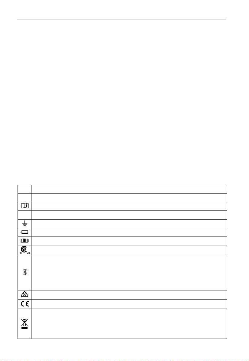
SYMBOLS
�
Caution! Refer to the explanation in this manual.
X
WARNING HAZARDOUS VOLTAGE. Risk of electric shock.
Consult user documentation.
The equipment is protected by double insulation or reinforced insulation.
T
Earth (Ground).
Fuse.
Battery.
®
Certified by CSA Group to North American safety standards.
Conforms to relevant South Korean EMC Standards.
Electromagnetic Compatibility:
Korea (KCC): Class A Equipment (Industrial Broadcasting & Communication Equipment)
[1]
This product meets requirements for industrial (Class A) electromagnetic wave
equipment and the seller or user should take notice of it. This equipment is intended for
use in business environments and is not to be used in homes.
Conforms to relevant Australian standards.
Complies with European Directives.
This product complies with the WEEE Directive marking requirements. The affixed
label indicates that you must not discard this electrical/electronic product in domestic
household waste. Product Category: With reference to the equipment types in the
WEEE Directive Annex I, this product is classed as category 9 “Monitoring and Control
Instrumentation” product. Do not dispose of this product as unsorted municipal waste.
[1]
2
Page 7

1. PRECAUTIONS AND SAFETY MEASURES
Safety information
The product complies with:
• UL/IEC/EN 61010-1, CAN/CSA C22.2 No. 61010-1, Pollution Degree 2, Measurement
CAT III 600 V MAX
• IEC/EN 61010-2-033
• IEC/EN 61010-2-032
• IEC/EN 61010-031 (test leads)
• EMC IEC/EN 61326-1
Measurement Category III (CAT III) is applicable to test and measure circuits connected
to the distribution part of the building’s low-voltage MAINS installation. This part of the
installation is expected to have a minimum of two levels of over-current protective devices
between the transformer and possible connecting points.
CENELEC Directives
The instrument conforms to CENELEC Low-voltage directive 2014/35/EU and Electromagnetic
compatibility directive 2014/30/EU.
X�Warnings: Read Before Using
To avoid the possibility of electric shock or personal injury:
• Use the Product only as specified in this manual or the protection provided by the
instrument may be compromised.
• Avoid working alone so assistance can be rendered.
• Test on a known signal source within the rated voltage range of the Product both
before and after use to ensure the Product is in good working conditions.
• Do not use the Product around explosive gas, vapor, or in damp or wet environments.
• Inspect the Product before use and do not use if it appears damaged. Check for cracks
or missing plastic. Pay particular attention to the insulation around the connectors.
• Inspect the test leads before use. Do not use if insulation is damaged or metal is exposed.
• Do not use the Product if it operates incorrectly. Protection may be impaired. When in
doubt, have the Product serviced.
• Check the test leads for continuity. Replace damaged test leads before using the Product.
• Have the Product serviced only by qualified service personnel.
• Use extreme caution when working around bare conductors or bus bars. Contact with
the conductor could result in electric shock.
• Do not hold the Product beyond the tactile barrier.
• Do not apply more than the rated voltage and CAT rating, as marked on the Product,
between the terminals or between any terminal and earth ground.
• Remove test leads from the Product before opening the Product case or battery cover.
• Never operate the Product with the battery cover removed or the case open.
• Use caution when working with voltages above 30 V AC RMS, 42 V AC peak, or 60 V
DC. These voltages pose a shock hazard.
• Do not attempt to connect to any circuit carrying voltage that may exceed the maximum
range of the Product.
3
Page 8

1. PRECAUTIONS AND SAFETY MEASURES
• Use the proper terminals, functions and ranges for your measurements.
• When using alligator clips, keep fingers behind the finger guards.
• Use only exact fuse replacement and specified replacement parts.
• When making electrical connections, connect the common test lead before
connecting the live test lead; when disconnecting, disconnect the live test lead before
disconnecting the common test lead.
• To avoid false readings that can lead to electrical shock and/or injury, replace or
recharge the batteries as soon as the low battery indicator appears. Check Meter
operation on a known source before and after use.
• Use only AA batteries, properly installed in the Meter case, to power the Product (see
Section 5.1: Battery Replacement).
• When servicing, use only specified user serviceable replacement parts.
• Adhere to local and national safety codes. Individual protective equipment must be used
to prevent shock and arc blast injury where hazardous live conductors are exposed.
• Only use the test lead provided with the Product or UL Listed Probe Assembly rated
CAT III 600 V or better.
• Do not use the HOT STICK (TIC 410A) to operate the AT-6000-R Receiver at voltages above 600 V.
• Remove the batteries if the Meter is not used for an extended period of time, or if
stored in temperatures above 122 °F (50 °C). If the batteries are not removed, battery
leakage can damage the Meter.
• Follow all battery care and charging instructions from the battery manufacturer.
This manual contains information and warnings that must be followed for safe operation
and maintenance of the instrument. If the Product is used in a manner not specified by the
manufacturer, the protection provided by the Product may be impaired. This Product meets water
and dust protection IP52 (Receiver) and IP40 (transmitter and signal clamp) per IEC 60529. Do NOT
operate outside during periods of rainfall. The Product is double insulated for protection per EN
61010-1 to CAT III 600 V.
CAUTION: Do not connect the Transmitter to a separate ground in Electrically Susceptible
Patient areas of a health care facility. Make the ground connection before disconnecting.
4
Page 9

2. KIT COMPONENTS
Your shipping box should include:
AT-6020 KIT AT-6030 KIT
AT-6000-R RECEIVER 1 1
AT-6000-T TRANSMITTER 1 1
TL-6000 TEST LEAD AND ACCESSORY KIT* 1 1
CC-6000 HARD CARRYING CASE 1 1
USER MANUAL 1 1
RECHARGEABLE BATTERIES - 12
BATTERY CHARGERS - 3
CT-400 SIGNAL CLAMP - 1
1.5 V AA (IEC LR6) BATTERY 12 -
*TL-6000 test lead and accessory kit includes:
• 2 x 1 m test leads (red, black)
• 1 x 7 m test lead (green)
Optional accessories:
HS-1 MAGNETIC HANGER
TL-7000-25M TEST LEAD (25 m long)
HOT STICK (TIC 410A)
• 2 x alligator clips (red, black)
• 1 x US Socket adapter
2.1 AT-6000-R Receiver
The AT-6000-R Receiver detects the signal in wires and cables using the following methods:
Active (using Transmitter)
The AT-6000-T Transmitter generates a signal capable of tracing either Energized or De-energized wires.
The main advantage this method is the ability to trace the path of the particular wire using
the Receiver. Since the signal is not present in any neighboring wires, the Receiver will
detect only the wire that is connected to the Transmitter.
The active tracing method is used when the Receiver is set to Quick Scan, Precision Tracing
or Breaker Locating.
Passive (without Transmitter)
The passive method utilizes the Receiver by tracing Energized wires between 90-600 V AC
through electromagnetic fields.
This method is both easy and convenient because it does not require the Transmitter.
However, the Receiver is not selective to a particular wire and will indicate any Energized
wire between 90-600 V AC.
This method is best for simple tracing applications where the wire is Energized and no other
wires are located nearby.
Passive tracing method is used when the Receiver is set to Non-contact voltage (NCV) detection mode.
Note: The Receiver will NOT detect signals from a wire through metal conduit or shielded
cable. Refer to Special Applications, section 4.4 “Tracing Wires In Metal Conduit” for
alternative tracing methods.
5
Page 10
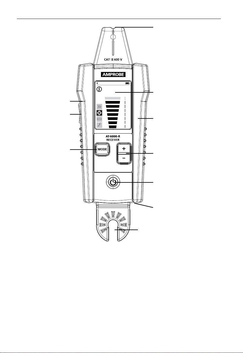
2. KIT COMPONENTS
TIP SENSOR
TACTILE BARRIER
VOLUME
ADJUSTMENT
BUTTON (+/-)
FUNCTION BUTTON
Toggles between
modes:
- Quick Scan
- Precision Tracing
- Breaker Locating
- NCV-contact detecion
(Non-contact voltage)
Figure 2.1: Overview of AT-6000-R Receiver
88
NCV
LCD DISPLAY
Full color TFT display
RUBBER OVER
MOLDED ENCLOSURE
SENSITIVITY ADJUSTMENT
BUTTON (+/-)
POWER BUTTON
Turns unit On / Off
BATTERY COMPARTMENT
(Back side)
HOT STICK ATTACHMENT POINT
(Do not use for voltage higher
than 600 V)
2.2 AT-6000-T Transmitter
6
Page 11

2. KIT COMPONENTS
The AT-6000-T Transmitter works on Energized and De-energized circuits up to 600 V AC/DC
in Category I through Category III electrical environments.
Transmitter signal modes:
High Signal (Hi) – The HIGH mode function is recommended for most wire tracing
applications on Energized and De-energized circuits including breaker location. This
function will be used the majority of the time.
Low Signal (Lo) – The LOW mode function is only appropriate for the most demanding and
precise wire tracing applications, as it limits the signal level generated by the Transmitter
in order to pinpoint the wire location more precisely. A lower signal level reduces coupling
to neighboring wires and metal objects, which avoids misreadings due to ghost signals. A
lower signal also prevents oversaturating the Receiver with a strong signal that covers too
large of an area.
Loop mode – This mode is initiated by pressing and holding this Hi button for two seconds.
It should be used when working with closed loop De-energized circuits, such as shorted
wires, shielded cables or De-energized wires that are grounded on the far-end.
How is the Loop function different from the Hi or Lo settings when using test leads?
Both HIGH and LOW modes generate a signal in all open branches of the De-energized
circuit. This is useful when tracing open wires. Hi/Lo modes will NOT work on wires that are
grounded on the far-end because the signal cannot be generated.
Loop mode generates a signal (current flow) in closed loop De-energized circuits only. Loop
mode is used to pinpoint the location of a short (because the current will not be able to
flow in open branches) and to trace wires that are grounded on the far end (because the
loop is closed via grand connection).
Note: Loop mode only works on De-energized circuits. It is automatically disabled when the
Transmitter is connected to an Energized line with test leads.
Figure 2.2a: Generating a signal with HIGH and LOW modes
Figure 2.2b: Generating a signal in Loop mode
7
Page 12

2. KIT COMPONENTS
Working with the Transmitter:
When the Transmitter is on and connected to the circuit with test leads, it checks for
voltage. A red Voltage Warning Indicator will light up if the Transmitter detects dangerous
voltage levels above 30 V AC/DC.
IMPORTANT!
The Voltage Warning Indicator light will blink when overvoltage (> 650 V AC/DC) is
detected. In case of overvoltage immediately disconnect the Transmitter from the circuit.
If the High (Hi) or Low (Lo) Signal button is pressed momentarily, the Transmitter starts
generating a tracing signal. Based on the detected voltage, the Transmitter automatically
switches to either:
• Energized mode (30 to 600 V AC/DC) generating 6 kHZ frequency
• De-energized mode (0 to 30 V AC/DC) generating 33 kHz frequency
Energized mode uses a lower transmission frequency (6 kHz) than De-energized mode
(33 kHz) to reduce signal coupling between wires. De-energized mode requires a higher
frequency in order to generate a reliable signal.
Energized mode: In Energized mode, the Transmitter draws a very low current from the
Energized circuit and generates a 6 kHz signal. This is a very important feature of the
Transmitter, since drawing current does not inject any signal that would harm sensitive
equipment connected to the circuit. The signal is also generated in a direct path between
the Transmitter and the power source, thus NOT placing a signal onto any branches enabling
wiring tracing directly back to the breaker panel. Please note that due to this feature, the
Transmitter has to be connected on the load side of the circuit.
De-energized mode: In De-energized mode, the Transmitter injects a 33 kHz signal onto the
circuit. In this mode, the signal will travel though all the circuit branches because it is
injected. The high frequency/low energy signal will not harm any sensitive equipment.
8
Page 13
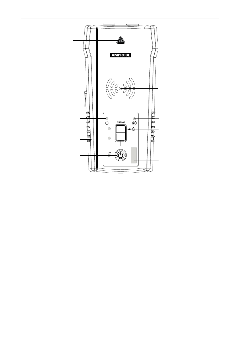
2. KIT COMPONENTS
VOLTAGE WARNING
INDICATOR
1. Red: Energized
2. Off: De-energized
3. Blinking: Overvoltage
VOLUME
ADJUSTMENT
BUTTON (+/-)
AT-6000-T
TRANSMITTER
TRANSMISSION MODE
INDICATOR
LOOP MODE INDICATOR
RUBBER OVERMOLDED
ENCLOSURE
ON / OFF BUTTON
HI
LO
MUTE INDICATOR
HIGH SIGNAL MODE
Press >2s for Loop mode
LOW (PRECISION) MODE
BATTERY STATUS
Figure 2.3: Overview of AT-6000-T Transmitter
ON/OFF: Short press to turn the Transmitter on. Long press >2s to turn the Transmitter off.
Volume adjustment: The volume can be changed by short presses on VOLUME UP/DOWN
buttons. In addition to mute, four volume levels are available. The chosen volume level will
be shown on LED display for a short time. If sound is muted, the MUTE LED light will be on.
The sound pattern is different depending on chosen operating mode.
Voltage Warning light: The warning light will be ON for Energized circuits (30 to 600 V
AC/DC), OFF for De-energized circuits (0 > 30 V AC/DC), and BLINKING if an overvoltage is
detected (> 650 V AC/DC).
LED display:
The LED diodes will blink with different rhythm depending on the chosen operating mode.
Transmitting in HIGH mode – Fast blinking,
Transmitting in LOW mode – Slow blinking,
Transmitting in LOOP mode – Alternating blinking.
High mode: Short press on HI pushbutton to turn on HIGH transmitting mode. Second short
press on HI button to turn off transmitting.
Low mode: Short press on LO pushbutton to turn on LOW transmitting mode. Second short
press on LO button to turn off transmitting.
Loop mode: Long press (>2s) on HI pushbutton to turn on Loop mode. Short or long press on
HI button to turn off Loop mode.
9
Page 14

2. KIT COMPONENTS
2.3 CT-400 Signal Clamp
(included with AT-6030 option for AT-6020)
The Signal Clamp accessory is used for applications when where is no access to the bare
conductors. The clamp attachment enables the Transmitter to induce a signal through the
insulation into either wires. The clamp works on low impedance closed circuits.
CONNECTORS TO
TRANSMITTER
JAW
TACTILE
BARRIER
JAW
RELEASE
TEST LEAD
Figure 2.4: Overview of CT-400 Signal Clamp
10
Page 15
3. MAIN APPLICATIONS
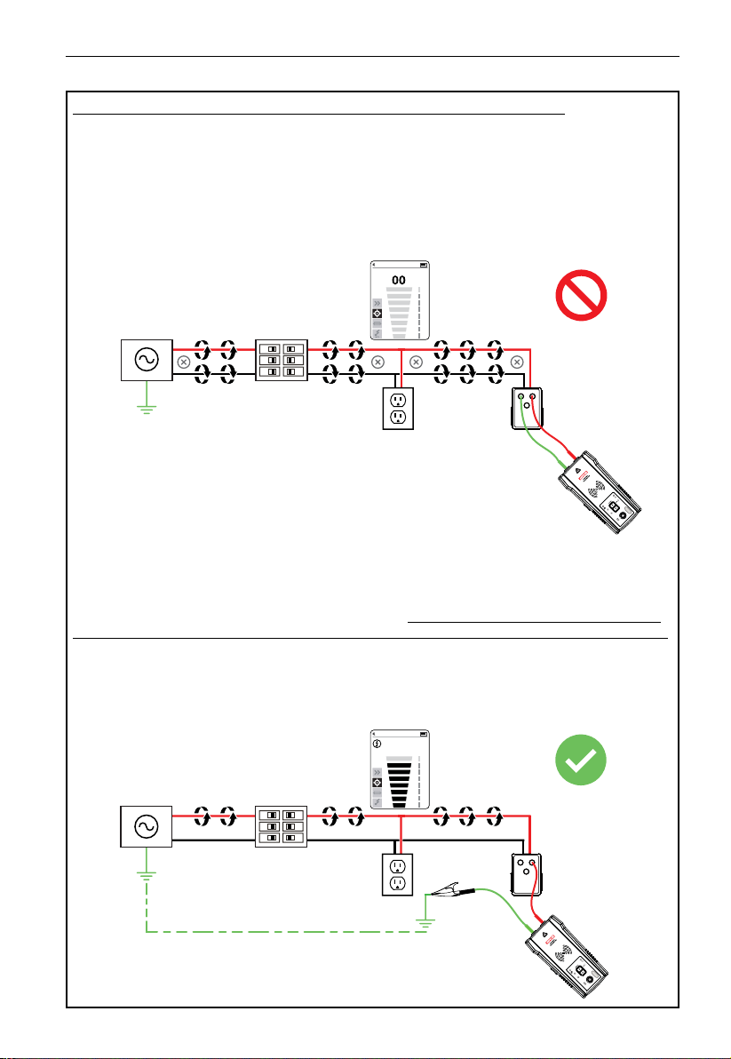
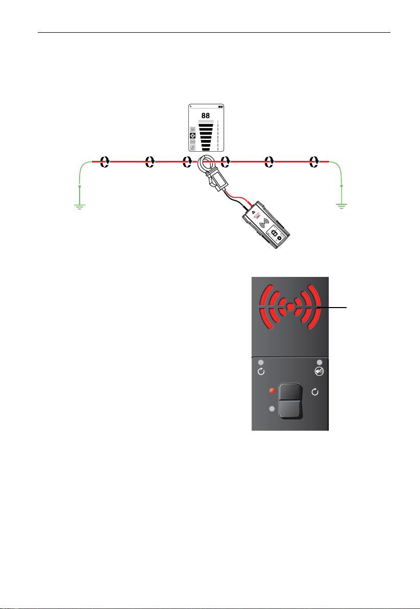
X� IMPORTANT NOTICE, PLEASE READ BEFORE STARTING TRACING
Avoiding signal cancellation problems with a separate ground connection
The signal generated by the Transmitter creates an electromagnetic field around the wire.
This field is what is detectable by the Receiver. The clearer this signal, the easier it is to trace
the wire.
If Transmitter is connected to two adjacent wires on the same circuit (for example, hot and
neutral wires on a Romax cable), the signal travels in one direction through the first wire
and then returns (in opposite direction) through the second. This causes the creation of two
electromagnetic fields around each wire with opposite direction. These opposing fields will
partially or completely cancel each other out, making wire tracing difficult if not impossible.
To avoid the cancellation effect, a separate ground connection method should be used.
The red test lead of the Transmitter should be connected to the hot wire of the circuit you
wish to trace, and the green lead to a separate ground, such as water pipe, ground stake,
metal grounded structure of the building, or outlet ground connection of an outlet on a
different circuit. It is important to understand that an acceptable separate ground is NOT
the grounding terminal of any receptacle on the same circuit as the wire you wish to trace.
If hot wire is Energized and the Transmitter is properly connected to a separate ground,
the red LED on the Transmitter will light up. The separate ground connection creates
maximum signal strength because the electromagnetic field created around the hot wire is
not being cancelled by a signal on the return path flowing along an adjacent wire (hot or
neutral) in the opposite direction, but rather through the separate ground circuit.
11
88
NCV
Page 16
AT-6000-T
TRANSMITTER
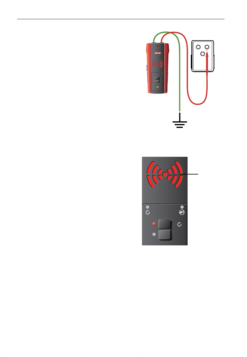
3. MAIN APPLICATIONS - TRACING ENERGIZED AND DE-ENERGIZED WIRES
3.1 Tracing – Energized and De-energized Wires
Connecting test leads to the Transmitter
1. Connect the green and red test leads to the
Transmitter (polarity does not matter).
2. Plug the socket adapter onto the receptacle and
connect the red lead to the Energized hot wire
(on the load side of the system). The signal will
ONLY be transmitted between the load-side
to which the Transmitter is connected and the
source of power (see Figure 3.1a).
3. Connect the green wire to a separate ground
(metal building structure, metal water pipe, or
ground wire on a separate circuit).
*Note: Please note that if working with GFCI
protected circuits, this method will trip the GFCI
protection. Refer to Special Applications, section 4.1
“GFCI-Protected Circuit Wire Tracing” for alternative
tracing methods.
Setting up the AT-6000-T Transmitter
1. Press ON/OFF key to turn on the Transmitter.
2. Verify that the test leads are properly
connected; the red LED voltage status
light should be on for circuits with voltage
above 30 V AC/DC, and it should be off for
De-energized circuits below 30 V AC/DC.
Note: Make sure to use the separate ground
connection as described above.
3. Select HIGH signal mode by pressing HI for
most applications. Screen will appear as
shown in Figure 3.1b. The LED display will
quickly begin to blink.
Note: The LOW signal precision mode can be
used to limit the signal level generated by the
Transmitter in order to more precisely pinpoint
wire location. A lower signal level reduces coupling
to neighboring wires and metal objects and helps
to avoid misreading due to ghost signals. A lower
signal also helps to prevent oversaturating the
Receiver with a strong signal that covers too large
an area. The LOW mode function is only used
for the most demanding and precise wire tracing
applications.
AT-6000-T
TRANSMITTER
SIGNAL
>2s
HI
LO
ON
Figure 3.1a: Proper connection with
separate ground
BLINKING
SIGNAL
>2s
HI
LO
Figure 3.1b: Transmitter indicator
showing signal in HIGH mode
12
Page 17

3. MAIN APPLICATIONS - TRACING ENERGIZED AND DE-ENERGIZED WIRES
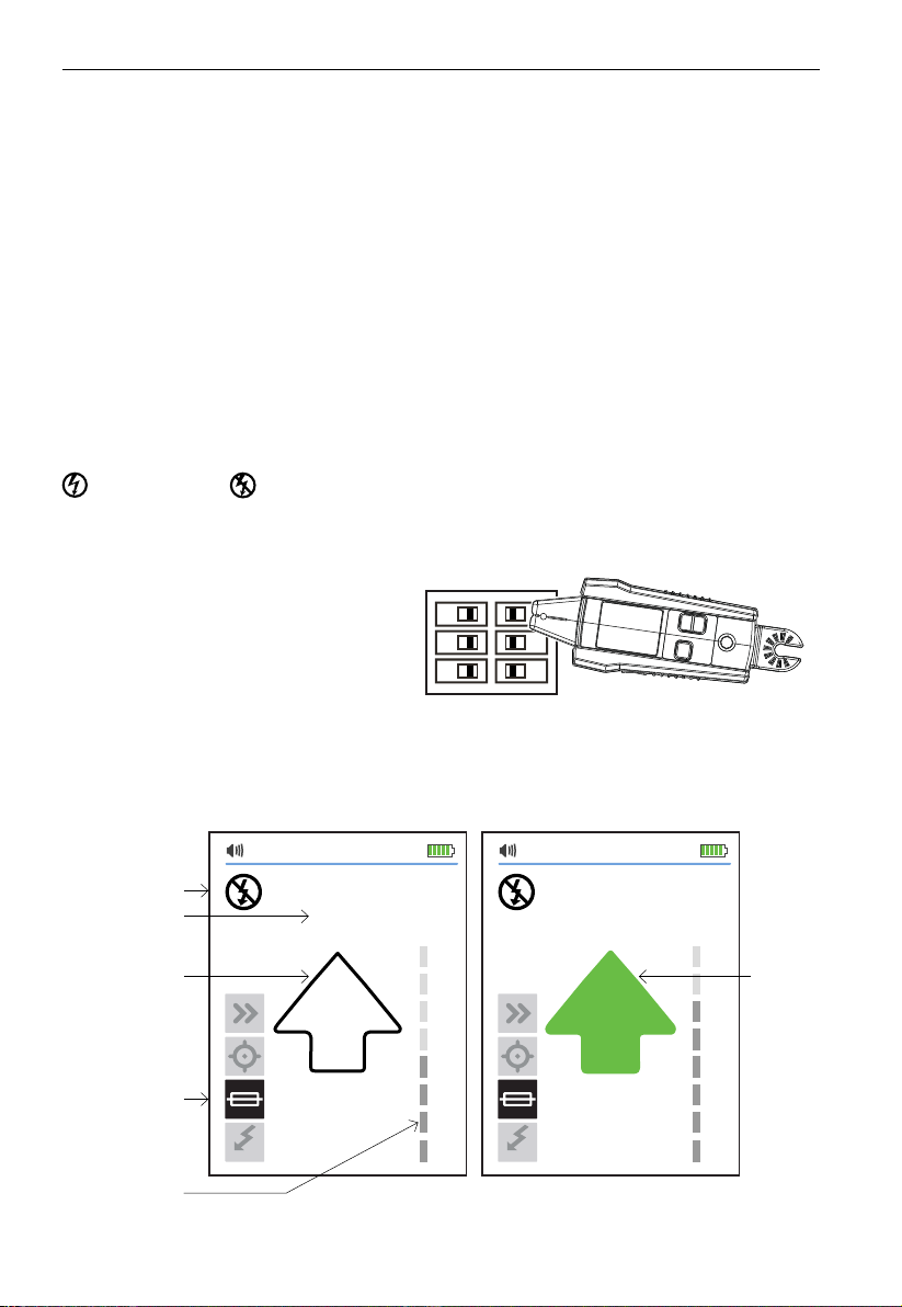
Using the AT-6000-R Receiver in Quick Scan Mode
Quick Scan mode detects wires at a longer distance (between a wire and the Receiver) but
with less precision than Precision Tracing or Breaker modes. This feature is used to verify that
the tracing signal is present and to quickly follow the path of the wire. Switch to Precision
Tracing mode to precisely pinpoint the wire, or to Breaker mode to locate a breaker.
1. Press ON/OFF push button to turn on the Receiver. It will automatically start in Quick
Scan mode, which is the default.
2. Scan a target area with the Tip Sensor to find a signal, then begin tracing the detected
wire. Increase or decrease sensitivity of the Receiver by pressing + or - on the keypad as
necessary.
3. For best results while tracing Energized wires, align groove on the Tip Sensor with wire
direction as shown in Figure 3.1c and Figure 3.1d. Signal may be not detected if not
properly aligned. To verify wire direction, periodically rotate the Receiver 90 degrees.
Signal strength will be the highest when wire is aligned with the Tip Sensor groove.
Depending on the detected signal, the Receiver automatically switches to either
Energized
manual setup is necessary.
Note: For best results, keep the Receiver at least 3 feet away from the Transmitter and test
leads to minimize signal interference.
or De-energized mode, and displays this information on the LCD. No
NC V
NC V
Figure 3.1c: Signal not detected Figure 3.1d: Signal detected
13
Page 18

3. MAIN APPLICATIONS - TRACING ENERGIZED AND DE-ENERGIZED WIRES
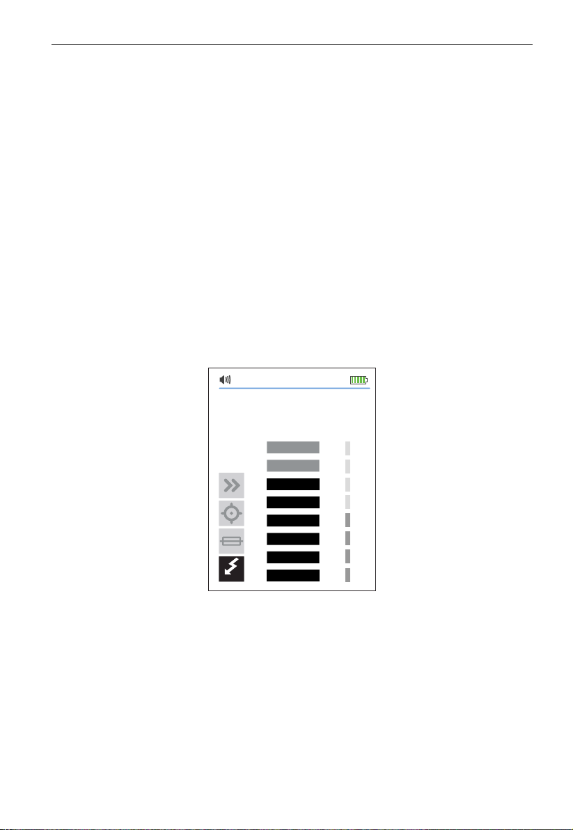
Using the AT-6000-R Receiver in Precision Tracing Mode
Use Precision Tracing mode to precisely pinpoint the wire location or the place of the fault.
The Receiver will indicate detected signal strength using a two digit readout, bar graph and
sound.
1. Press the MODE button until the Precision Tracing function is selected.
2. Scan target area with the Tip Sensor to find the highest signal level. While tracing,
periodically adjust sensitivity to keep the signal strength near 50. Increase or decrease
sensitivity by pressing + or - on the keypad. If the signal is too strong for precise
locating, change the Transmitter to LOW mode.
3. For best results while tracing Energized wires, align groove on the Tip Sensor with wire
direction as shown in Figure 3.1e. Signal may be not detected if not properly aligned.
To verify wire direction, periodically rotate the Receiver 90 degrees. Signal strength will
be the highest when wire is aligned with the Tip Sensor groove.
Depending on the detected signal, the Receiver automatically switches to either
Energized
manual setup is necessary.
or De-energized mode, and displays this information on the LCD. No
Align
Figure 3.1e: Aligning the tip sensor groove
Note: For best results, keep the Receiver at least 3 feet from the Transmitter and test leads
to minimize signal interference.
Sound volume
Energized
88
Quick Scan
Precision Tracing
Breaker Locating
Non-contact voltage
detection, passive tracing
NC V
Figure 3.1f: Screen display
Tip
groove
Battery status
Signal strength (0-99)
Sensitivity level (1-8)
Bargraph - proportional
to signal strength
14
Page 19

3. MAIN APPLICATIONS - TRACING ENERGIZED AND DE-ENERGIZED WIRES
AT-6000-T
TRANSMITTER
ON
HI
LO
SIGNAL
>2s
3.2 Identifying Breakers and Fuses (Energized and De-energized)
Breaker mode automatically adjusts the sensitivity of the Receiver. As a result, the Receiver
will pinpoint and indicate just one correct breaker. This enhancement helps to remove signal
strength analysis from the breaker identification process that is typical for less advanced
wire tracers.
Note: For breaker locating, a simplified direct connection to hot and neutral wires can be
used because these wires are separated at the breaker panel. There is no risk of signal
cancellation effect if wires are at least a few inches away from each other. However, the
separate ground connection (see pg. 11) should be used for superior results specifically if
wires need to be traced in addition to breaker identification.
The simplified direct connection to hot and neutral wire will NOT trip the GFCI circuit.
AT-6000-T
TRANSMITTER
SIGNAL
>2s
HI
LO
ON
Figure 3.2a: Simplified direct connection
Connecting the test leads
1. Connect the Transmitter using either simplified direct connection or separate ground
connection.
2. If the simplified direct connection method is used, connect the test leads directly to
the hot and neutral wires. While locating a breaker, wires will not be traceable as the
signals will cancel each other out.
3. For separate ground connection, first connect the red lead to the Energized hot wire
on the load side of the system. The signal will ONLY be transmitted between the outlet
to which the Transmitter is connected and the source of power.
4. Connect the green lead to a separate ground, such as a metal building structure, metal
water pipe, or ground wire on a separate circuit.
Setting up the AT-6000-T Transmitter
1. Press the ON/OFF key to turn on the Transmitter.
2. Verify that the test leads are properly connected. The red LED voltage status light will
illuminate for Energized circuits with a voltage above 30 V AC/DC. If the voltage is
De-energized, the light will be off.
3. Select the HIGH signal mode for Breaker Locating.
Figure 3.2b: Separate ground connection
(Preferred)
15
Page 20
3. MAIN APPLICATIONS – LOCATING BREAKERS
Using the AT-6000-R Receiver
1. Press the ON/OFF push button to turn on the Receiver and continue pressing the MODE
button until Breaker Locating mode is selected.
2. Align the groove on the Tip Sensor with the breaker lengthwise (See Figure 3.2c).
3. Scan all breakers in any order. Breakers can be scanned multiple times. The Receiver
records the highest signal level and will automatically adjust sensitivity. The Receiver
may beep and the green arrow may light up several times during this step.
4. Locate the breaker by scanning all breakers again; the Receiver should indicate only
one breaker.
Important note: Differentiation in breaker designs, height and internal contact structure
may affect the precision of breaker identification. For most reliable results, remove the
breaker panel cover and perform a scan on the wires instead of the breakers.
If more than one breaker is indicated during the last step, continue scanning the indicated
breakers until only one is positively identified.
Depending on the detected signal, the Receiver automatically switches to either Energized
or De-energized mode, and displays this information on the LCD. No manual setup
necessary. The automatic sensitivity adjustment can be reset or adjusted using the +/- buttons.
Usage Tip: The accuracy of breaker
identification results can be verified by
switching the Receiver to Precision Tracing
mode and checking that the signal level of
the breaker identified by the Receiver is
the highest among all the breakers.
Before starting the next locating process
for new circuit or a branch, connect the
Transmitter and reset the Receiver by
either pressing + button to select high
sensitivity or switching the Receiver off
and then on.
Energized/
De-energized
signal
detected
Signal
Strength
55
Figure 3.2c: Aligning the Tip
Sensor groove with the breaker
75
is
Breaker
searching
Breaker
locating
Sensitivity
level
NC V
Breaker
found
NC V
Figure 3.2d: Reading the Receiver screen
16
Page 21
3. MAIN APPLICATIONS – LOCATING BREAKERS
3.3 Non-contact Voltage Mode (NCV) and Passive Tracing
The NCV (Non-Contact Voltage) mode is used to verify if the wire is Energized and to
perform tracing without the use of the Transmitter. The Receiver will detect and trace an
Energized cable if the voltage is between 90 V and 600 V AC and between 40 and 400 Hz.
No current flow is necessary.
Note: For safety, always verify that wires are De-energized with an additional tester before
working with them.
NCV mode operation
1. Press ON/OFF push button to turn on the Receiver.
2. Continue pressing MODE button until the Non-Contact Voltage function is selected.
Passive tracing
Scan the target area with the Tip Sensor to find the highest signal level. While tracing,
periodically adjust the sensitivity to keep the signal strength near 50. Increase or decrease
sensitivity by pressing.
Verifying if wire is Energized
Hold the Receiver with the Tip Sensor against the wire. For precise pinpointing of hot wire
versus neutral wire, increase or decrease sensitivity by pressing + or - on the keypad.
75
NC V
Figure 3.3: Voltage detection in NCV mode using Tip Sensor
17
Page 22

4. SPECIAL APPLICATIONS
4.1 GFCI-Protected Circuit Wire Tracing: Connecting the AT-6000-T Transmitter to
GFCI Protected Circuits
Connecting the Transmitter to an Energized GFCI protected circuit using a separate ground
method will trip the GFCI protection. Use the following methods to work with GFCI
protected circuits. For a De-energized GFCI-protected outlet that is not tripped, you can
connect test leads directly to the outlet contacts using the De-energized Tip Sensor mode.
Method 1 – Bypass the GFCI circuitry to avoid tripping GFCI:
(for Energized GFCI-protected outlets only)
• Remove the protective receptacle wall plate.
• Using the alligator clip, attach the red test lead to the screw to connect the Energized
hot wire to the receptacle.
• Connect the green test lead using a separate ground method.
• Perform tracing as described in the Quick Scan or Precision Tracing sections.
Method 2 – Do NOT use separate ground to avoid tripping GFCI:
(for GFCI-protected outlets and breakers)
• Connect the Transmitter with the test leads to the Neutral and Hot wires.
• Perform tracing as described in one of the following modes: Quick Scan, Precision
Tracing or Breaker Locating.
Note: This type of connection causes signal coupling and reduces signal strength. If the
signal is too weak or untraceable, use Method 3.
Method 3 - De-energize the circuit:
(for GFCI-protected breakers)
• Connect the Transmitter directly to the wire as described in wire tracing modes (Quick
Scan and Precision).
• Perform tracing as described in one of the following modes: Quick Scan, Precision
Tracing or Breaker Locating.
4.2 Finding Breaks/Opens
It is possible to pinpoint the exact location where a wire is broken using the Precision
Tracing mode, even if the wire is located behind walls, floors or ceilings.
1. Make sure that wire is De-energized.
2. Use the steps described in the Precision Tracing mode to connect the Transmitter and
perform tracing.
3. For best results, ground all De-energized wires that run in parallel with the black test lead.
Figure 4.2: Locating a break or open
18
Page 23

4. SPECIAL APPLICATIONS
The tracing signal generated by the Transmitter is conducted along the wire as long as there is
continuity in the metal conductor. To find a fault, trace the wire until the signal stops. To verify
the fault’s location, move the Transmitter to the other end of the wire and repeat, tracing from
the opposite end. If signal stops at the exact same location, the fault has been located.
Note: If the place of the fault is not found, the result may be a high resistance break
(partially open circuit). Such a break would stop higher currents from flowing but will
conduct the tracing signal through the break. Such faults will not be detected until the wire
is completely open.
4.3 Finding Shorts
Shorted wires will cause a breaker to trip. To correct this, disconnect the wires and make
sure the ends of the wires on both sides of the cable are isolated from each other and other
wires or loads.
1. Connect the Transmitter with the test leads to the circuit as shown in Figure 4.3.
2. Turn the Transmitter to Loop mode by pressing HIGH button for two seconds. Verify that
the Loop LED is ON.
3. Setup the Receiver to a wire tracing mode (either Quick Scan or Precision Tracing).
Start tracing the cable until the signal stops. To verify the place of the fault, move the
Transmitter to the other end of the wire and repeat tracing from the opposite end. If the
signal stops at the exact same location the fault has been located.
Figure 4.3: Tracing a cable to find shorts
Note: This method will be affected by signal cancellation effect. Expect a relatively weak signal.
4.4 Tracing Wires in Metal Conduit
The Receiver is unable to pick up the signal from a wire through a metal conduit. The metal
conduit will completely shield the tracing signal.
Note: The Receiver will be able to detect wires in a non-metallic conduit. For these
applications follow general tracing guidelines.
To trace wires in a metal conduit:
1. Use the Quick Scan or Precision Tracing modes.
2. Open junction boxes and use the Receiver Tip Sensor to detect which wire in the
junction box is carrying the signal.
3. Move from junction box to junction box to follow the path of the wire.
Note: Applying a signal directly to the conduit will send the signal through all the conduit
branches, making tracing a particular conduit path impossible.
19
Page 24

4. SPECIAL APPLICATIONS
4.5 Tracing Non-Metallic Pipes and Conduits
The Transmitter can indirectly trace plastic conduits and pipes using the following steps:
1. Insert fish tape or wire inside the conduit.
2. Connect the Transmitter with the red test lead to the fish tape and the green ground
wire to a separate ground (see wire tracing section 3.1 for further set-up instructions).
3. Set the Receiver to Quick Scan or Precision Tracing modes to trace the conduit.
4. The Receiver will pick up the signal conducted by the fish tape or wire through the conduit.
4.6 Tracing Shielded Wires
Shielded wire prevents the Receiver from detecting a tracing signal when following the
standard user instructions. To effectively trace shielded wire, follow these procedures.
If shielded wire is grounded at the far-end:
1. Setup Transmitter in Loop mode by pressing HIGH button for two seconds. Verify that
the Loop LED is ON.
2. Disconnect the ground on the near-end of the shielded wire and connect the shield to
one of the terminals of the Transmitter (polarity does not matter) with a test lead.
3. Connect the second output of the Transmitter to a separate ground.
4. Set the Receiver to a wire tracing mode to trace the shield (refer to section 3.1).
Figure 4.6a: Tracing a shielded wire grounded at the far-end
If shielded wire is disconnected from ground at the far-end:
1. Set the Transmitter to a wire tracing mode (see section 3.1).
2. Disconnect the ground on the near-end of the shielded wire and connect the shield to
one of the terminals of the Transmitter (polarity does not matter) with a test lead.
3. Connect the second output of the Transmitter to a separate ground.
4. Set the Receiver to a wire tracing mode to trace the shield.
Figure 4.6b: Tracing a shielded wire disconnected from the ground at far-end
20
Page 25

4. SPECIAL APPLICATIONS
4.7 Tracing Underground Wires
The AT-6000 can trace Energized and De-energized wires underground the same way it can
locate wires behind walls or floors.
Perform tracing using a separate ground connection. The HOT STICK (TIC 410A) attachment can
be used to make tracing more ergonomic and convenient.
Figure 4.7: Tracing Underground Wires
4.8 Tracing Low Voltage Wires and Data Cables
The AT-6000 can trace data, audio and thermostat cables (to trace shielded data cables, refer
to section 4.6 “Tracing Shielded Wires”).
Trace data, audio, and thermostat cables
1. Connect the Transmitter using the separate ground method (see section 3.1).
2. Set the Receiver to a wire tracing mode and trace the wire.
4.9 Sorting Bundled Wires
Identify a specific wire in a bundle
1. Connect the Transmitter and set to a wire tracing mode. If connecting to an Energized
wire, make sure the Transmitter is connected on the load side.
2. Select a wire tracing mode on the Receiver.
3. One at a time, pull each wire away from the others and touch it with the Tip Sensor. The
strongest signal indicates the proper wire in the bundle.
4. Adjust the Receiver sensitivity as required with +/- buttons.
Figure 4.9: Identifying a specific wire in a bundle
21
Page 26
4. SPECIAL APPLICATIONS
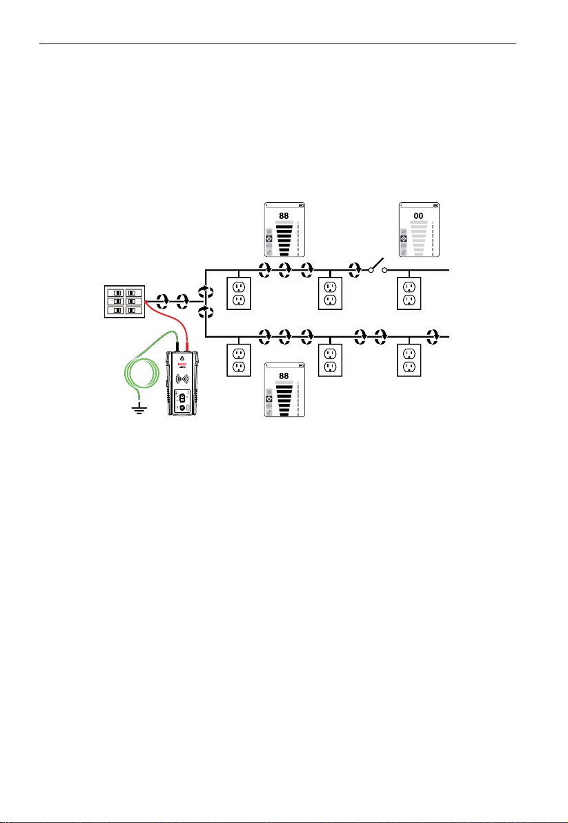
4.10 Mapping a Circuit using Test Leads Connection
Mapping a circuit can be only performed on a De-energized circuit when using test leads
connection.
1. Switch the breaker to the OFF position.
2. Set up the Transmitter and Receiver as described in the Precision Tracing section 3.1.
3. Scan face plates of receptacles and wires connecting loads with the Tip Sensor of the
Receiver
4. All the wires, receptacles and loads that have a strong signal as indicated by the Receiver
are connected to the breaker.
Figure 4.10: Mapping a circuit using test leads connection
4.11 Tracing Breakers on Systems with Light Dimmers
Light dimmers can produce a significant amount of electrical “noise” that consists of
multi-frequency signals. In some rare situations, the Receiver can misread this noise, often
called a “ghost” signal, as a Transmitter - generated signal. Therefore, the Receiver may
provide wrong readings.
When locating breakers or fuses on systems with light dimmers, the dimmer should be off
(the light switch is off). This prevents the Receiver from indicating a wrong breaker/fuse.
4.12 Signal Clamp - Closed Loop Circuits
Closed loop, De-energized and low impedance circuits
The clamp accessory is used for applications where there is no access to a bare conductor
to connect the test leads. When the clamp is connected to the Transmitter, it enables the
Transmitter to induce a signal to the Energized or De-energized wire through the insulation.
Typical applications of the Signal Clamp include tracing conduits or shields grounded on
both ends. For signal cables and De-energized wires or loads, temporarily ground the circuit
on both ends to perform tracing.
22
Page 27
4. SPECIAL APPLICATIONS
AT-6000-T
TRANSMITTER
Connecting the Signal Clamp
1. Connect the CT-400 test leads to the terminals of the Transmitter (polarity does not
matter).
2. Clamp the CT-400 Signal Clamp around the conductor. To increase the signal strength,
wind a few turns of the conductor wire around the clamp if possible.
Figure 4.12a: Connecting the clamp
Setting up the AT-6000-T Transmitter
1. Press the ON/OFF key to turn on the Transmitter.
The red LED voltage status indicator should be OFF
when the clamp is connected and when working
with either Energized or De-energized systems.
2. Press HIGH signal mode and hold
pushbutton for >2 seconds to select the
Loop mode on the Transmitter. The clamp
mode generates a boosted 6 kHz signal in order to
provide superior tracing results. The screen on the
Transmitter should appear as in Figure 4.12b.
Using the AT-6000-R Receiver
1. Press the ON/OFF push button to turn on the Receiver.
2. Select either Quick Scan or Precision Tracing mode.
3. Hold the Receiver with the Tip Sensor facing the
target area.
4. Scan the target area with the Tip Sensor to find the highest signal level. While tracing,
periodically adjust the sensitivity to keep the signal strength near 50. Increase or
decrease the sensitivity by pressing + / - on the keypad.
5. Receiver Positioning: For best results while tracing Energized wires, align the groove on
the Tip Sensor with the wire direction as shown. The signal may be lost if not properly
aligned.
6. To verify the wire direction, periodically rotate the Receiver 90 degrees. Signal strength
will be highest when wire is aligned with the Tip Sensor groove.
SIGNAL
>2s
HI
LO
Figure 4.12b: Transmitter indicator
showing signal in Loop mode
BLINKING
23
Page 28

4. SPECIAL APPLICATIONS
4.13 Signal Clamp - Mapping Circuits
The clamp accessory can be used to map loads to the specific breakers on both Energized
and De-energized circuits. There is no need to disconnect the power.
1. Connect the CT-400 test leads to the terminals of the Transmitter (polarity does not
matter) and select HIGH mode.
2. Clamp the CT-400 around the hot (line) wire at the breaker panel.
3. Select Quick Scan mode on the Receiver with the highest sensitivity level.
Scan the face plates of receptacles and wires by touching them with the Tip Sensor of the
Receiver. All the wires, receptacles and loads that the Receiver indicates in the Quick Scan
mode are connected to the breaker.
Note: Expect a relatively weak signal. For best performance, install fully charged high
capacity rechargeable batteries to the Transmitter. Use the “Mapping a circuit using test
leads connection” method if a much stronger signal is required.
Figure 4.13a: Using the Signal Clamp to map loads to specific breakers
Align
Tip
groove
Figure 4.13b: Aligning the Tip Sensor groove
*Note: For best results, keep the Receiver at least 3 feet from the Transmitter and its test
leads to minimize signal interference and improve wire tracing results.
24
Page 29
5. MAINTENANCE
5.1 Battery Replacement
Changing the Transmitter Batteries
The battery compartment on the back of the Transmitter is designed to make it easy for
the user to change the batteries. A screw is added to secure the battery in case the unit is
dropped. Eight (8) AA alkaline or rechargeable NiMH batteries may be used. NiMH batteries
need to be removed to be charged.
Note: Batteries do not come pre-installed in the Transmitter.
1. Make sure that the Transmitter is turned off and disconnected from the circuit.
2. Use a star screw driver to unscrew the battery compartment screws.
3. Remove the battery cover.
4. Install batteries.
5. Replace the battery cover and secure it with the screws.
8 x AA batteries
Figure 5.1: Changing the Transmitter batteries
25
Page 30

5. MAINTENANCE
Manual Selecting of Transmitter Battery Type
The type of batteries being used-Alkaline or rechargeable NiMH-are recognized
automatically during power up of the device or may be defined manually by the user.
Set battery type as alkaline:
1. Make sure that the Transmitter is turned off.
2. Press and hold the VOLUME UP (+) button.
3. While volume up button is pressed, press the POWER ON button. The chosen battery
type will be alkaline.
Set battery type as rechargeable NiMH:
1. Make sure that the Transmitter is turned off.
2. Press and hold the VOLUME DOWN (-) button.
3. While volume down button is pressed, press the POWER ON button. The chosen battery
type will be rechargeable NiMH.
If the battery type is not defined manually, it will be recognized automatically. Automatic
battery type recognition draws more current and can be unreliable if inadequate or
old batteries are used. The automatic battery recognition can also be unreliable if the
rechargeable batteries have not been charged in over one month.
Transmitter Battery Status
Related to 8 AA batteries same type and connected in series.
BATTERY TRESHOLD ALKALINE
Device will power off if voltage is below 6.9 V
Battery empty – RED LED blinking if voltage is > 7.3 V and < 9.4 V
0-10% - RED LED is ON for voltages > 9.6 V and < 9.9 V
10-40% - Two yellow LEDs are ON for voltages > 10 V and < 10.8 V
40-75% - Three green LEDs are ON or voltages > 10.9 V and < 12 V
> 75% - Four green LEDs are ON for voltages > 12 V
BATTERY TRESHOLD NiMH
Device will power off if voltage is below 6.9 V
Battery empty – RED LED blinking if voltage is > 7.1 V and < 7.3 V
0-10% - RED LED is ON for voltages > 7.4 V and < 7.6 V
10-40% - Two yellow LEDs are ON for voltages > 7.7 V and < 8.5 V
40-75% - Three green LEDs are ON or voltages > 8.6 V and < 9.7 V
> 75% - Four green LEDs are ON for voltages > 9.8 V
26
Page 31

5. MAINTENANCE
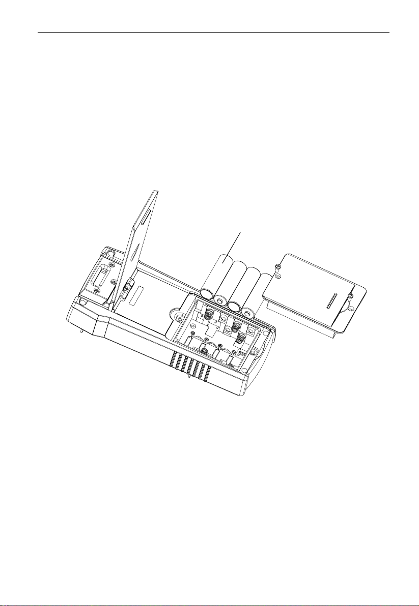
Changing the Receiver Batteries
The battery compartment on the back of the Receiver is designed to make it easy for the user to
change the batteries. Four (4) AA 1.5 V alkaline or 1.2 V rechargeable batteries may be used.
Note: Batteries do not come pre-installed in the Receiver.
1. Make sure that the Receiver is turned off.
2. Use a screw driver to unscrew the captive screw.
3. Remove the battery cover.
4. Install batteries.
5. Replace the battery cover and secure it with the provided screw.
4 x AA batteries
Figure 5.2: Changing the Receiver batteries
Note: The Receiver automatically recognizes if batteries are alkaline or rechargeable and
adapts the battery indication to provide the right information.
Old rechargeable batteries and certain alkaline batteries may not provide accurate battery
level indication. Turn on the device while holding the volume + button to automatically
adjust battery indication for rechargeable or alkaline batteries.
27
Page 32

5. MAINTENANCE
5.2 Fuse Replacement
Transmitter Fuse Replacement:
X�
Warning: To avoid shock, injury, or damage to the Transmitter, disconnect test leads
before opening case.
1. Disconnect all test leads from the Transmitter.
2. Make sure the Transmitter is turned off.
3. Use a star screw driver to unscrew the tilt-stand screws.
4. Remove the battery door and remove all batteries.
5. Use a star screw driver to unscrew holding screws.
6. Remove the back cover by pulling it upwards as shown in figure 5.3.
7. Remove the fuse from the fuse holder.
8. Insert the new fuse (1.6 A, 700 V MAX, FAST Ø 6X32 mm) in the fuse holder.
9. Insert the back cover, secure it with the holding screws and tighten with a star screw driver.
Fuse
Figure 5.3: Transmitter fuse replacement
28
Page 33

6. SPECIFICATIONS
Features AT-6000-R AT-6000-T CT-400
Measurement
Category
Operating
Voltage
Operating
Frequency
Hazardous
Voltage Detection
Signal Indications Numeric bar graph display
Response Time Tip Sensor (Energized /
Current Output of
Signal (typical)
Signal Voltage
Output (nominal)
Range Detection
(open air)
CAT III 600 V CAT III 600 V CAT IV 600 V,
0 to 600 V AC/DC 0 to 600 V AC/DC 0 to 1000 V AC
Energized: 6.25 kHz
De-Energized: 32.768 kHz
See NCV detection > 30 V AC/DC N/A
and audible beep
De-energized): 500 ms
NCV: 500 ms
Battery voltage
monitoring: 5 sec
N/A Energized circuit:
N/A De-energized circuit:
Tip Sensor (Energized):
Max distance via air: up to
20 ft (6.1 m)
Pinpointing: approx. 1.97
in (5 cm)
Tip Sensor (De-energized):
Max distance via air: up to
14.7 ft (4.5 m)
Pinpointing: approx. 1.97
in (5 cm)
NCV detection (40 to 400 Hz):
Max. sensitivity: 90 V, up
to 6.56 ft (2 m)
Min. sensitivity: 600 V, up
to 0.39 in (1 cm)
Energized: 6.25 kHz
De-Energized: 32.768 kHz
LEDs and audible beep N/A
Line voltage monitoring:
1 sec
Battery voltage
monitoring: 5 sec
HI mode: 60 mA RMS
LO mode: 30 mA RMS
De-energized circuit:
HI mode: 130 mA RMS
LO mode: 40 mA RMS
Loop mode: 160 mA RMS
LOW: 29 V RMS, 120 Vp-p
HIGH: 33 V RMS, 140 Vp-p
With CT-400:
Loop model: 31 V RMS,
120 Vp-p
N/A N/A
CAT III 1000 V
Wire tracing: 32.768 kHz
AC current measurement:
45 Hz to 400 Hz
Instantaneous
1 mA/A for AC current
measurement with
multimeter
De-energized circuit:
2.4 V RMS, 24 Vp-p
29
Page 34

6. SPECIFICATIONS
General specifications
Features AT-6000-R AT-6000-T CT-400
Display Size LCD 2.5 in (6.35 cm) LEDs N/A
Display Dimensions
(W x H)
Display Resolution 240(RGB) x 320 pixels N/A N/A
Display Type TFT-LCD (262 K) LEDs N/A
Display Color True, 16bit/color Operating mode LEDs: red
Booting Time < 3 sec < 2 sec N/A
Backlight Yes N/A N/A
Operating
Temperature
Operating Humidity 45%: -4 °F to <50 °F
Storage Temperature
and Humidity
Operating Altitude 0 to 6561 ft (2000 m) 0 to 6561 ft (2000 m) 0 to 6561 ft (2000 m)
Transient Protection N/A 6.00 kV (1.2/50µS surge) N/A
Pollution Degree 2 2 2
IP Rating IP 52 IP 40 IP 40
Drop Test 3.28 ft (1 m) 3.28 ft (1 m) 3.28 ft (1 m)
Power Supply 4 x AA (alkaline or NiMH
Power Consumption
(typical)
Battery Life (typical) Approx. 16 h Hi/Lo mode: approx. 25 h
Low Battery
Indication
Fuse N/A 1.6 A, 700 V, fast-acting,
Maximum
Conductor Size
Dimensions
(L x W x H)
Weight
(batteries installed)
Certifications
1.45 x 1.93 in
(36.72 x 48.96 mm)
-4 °F to 122 °F
(-20 °C to 50 °C)
(-20 °C to <10 °C)
95%: 50 °F to <86 °F
(10 °C to <30 °C)
75%: 86 °F to <104 °F
(30 °C to <40 °C)
45%: 104 °F to 122 °F
(40 °C to 50 °C)
-4 °F to 158 °F
(-20 °C to 70 °C), <95% RH
rechargeable)
110 mA Hi/Lo mode: 70 mA
Yes Yes N/A
N/A N/A 1.26 in (32 mm)
Approx. 7.2 x 2.95 x 1.69 in
(183 x 75 x 43 mm)
Approx. 0.6 lb (0.27 kg) Approx. 1.25 lb (0.57 kg) Approx. 0.25 lb (0.114 kg)
P
N/A N/A
N/A
Battery status LEDs:
green, yellow, red
-4 °F to 122 °F
(-20 °C to 50 °C)
45%: -4 °F to <50 °F
(-20 °C to <10 °C)
95%: 50 °F to <86 °F
(10 °C to <30 °C)
75%: 86 °F to <104 °F
(30 °C to <40 °C)
45%: 104 °F to 122 °F
(40 °C to 50 °C)
-4 °F to 158 °F
(-20 °C to 70 °C), <95% RH
8 x AA (alkaline or NiMH
rechargeable)
Loop mode with Clamp:
90 mA
Consumption without
signal transmission: 10 mA
Loop mode: approx. 18 h
Ø 6x32mm
Approx. 7.2 x 3.66 x 1.97 in
(183 x 93 x 50 mm)
P
32 °F to 122 °F
(0 °C to 50 °C)
95%: 50 °F to <86 °F
(10 °C to <30 °C)
75%: 86 °F to <104 °F
(30 °C to <40 °C)
45%: 104 °F to <122 °F
(40 °C to <50 °C)
-4 °F to 140 °F
(-20 °C to 60 °C), <95% RH
N/A
N/A
N/A
N/A
Approx. 5.9 x 2.75 x 1.18 in
(150 x 70 x 30 mm)
P
30
Page 35

6. SPECIFICATIONS
Accessory specifications
Features ADPTR-SCT TL-6000
Measurement Category CAT II CAT III (test leads)
Operating Voltage and Current 0 to 120 V AC, 4 A, max. 1000 V, 16 A max. (red/green leads)
Operating Frequency 50 Hz to 60 Hz N/A
Operating Temperature 32 °F to 122 °F
(0 °C to 50 °C)
Operating Humidity 95%: 50 °F to <86 °F
Storage Temperature and
Humidity
Operating Altitude 0 to 6561 ft (2000 m) 0 to 6561 ft (2000 m)
Pollution Degree 2 2
IP Rating IP 40 IP 20
Drop Test 3.28 ft (1 m) 3.28 ft (1 m)
Dimensions Approx. 2.95 x 1.97 x 2.56 in
Weight Approx. 0.125 lb (0.057 kg) Approx. 0.75 lb (0.34 kg)
Certifications
(10 °C to <30 °C)
75%: 86 °F to <104 °F
(30 °C to <40 °C)
45%: 104 °F to <122 °F
(40 °C to <50 °C)
-4 °F to 140 °F
(-20 °C to 60 °C), <95% RH
(75 x 50 x 65 mm)
CAT IV (alligator clips)
600 V, 16 A max. (black lead)
600 V, 10 A max. (alligator clips)
32 °F to 122 °F
(0 °C to 50 °C)
95%: 50 °F to <86 °F
(10 °C to <30 °C)
75%: 86 °F to <104 °F
(30 °C to <40 °C)
45%: 104 °F to <122 °F
(40 °C to <50 °C)
-4 °F to 140 °F
(-20 °C to 60 °C), <95% RH
Red/black leads: 3.28 ft (1 m)
Green lead: 22.97 ft (7 m)
Alligator clips:
approx. 3.74 x 1.77 x 0.94 in
(95 x 45 x 24 mm)
31
Page 36

Page 37

AT-6000
Détecteur de câbles avancé
AT-6020
AT-6030
Manuel de l’utilisateur
Français
8/2017, 6009478 Rév. B
©2017 Amprobe Test Tools.
Tous droits réservés. Imprimé en Chine.
Page 38

Limites de garantie et de responsabilité
Ce produit Amprobe sera exempt de vices au niveau des matériaux et de la fabrication pendant
un an à partir de la date d’achat sauf législation locale contraire. Cette garantie ne s'applique pas
aux fusibles, aux piles jetables ni à tout endommagement accidentel du produit par suite d'une
mauvaise utilisation, d'une modication, contamination, négligence ou d'un fonctionnement ou
manipulation dans des conditions anormales. Les revendeurs ne sont pas autorisés à proposer une
quelconque autre garantie pour le compte d’Amprobe. Pour bénécier de la garantie, renvoyez
le produit accompagné d'un justicatif d'achat auprès d'un centre de services agréé par Amprobe
ou à un distributeur ou revendeur Amprobe. Voir la section Réparation pour tous les détails.
CETTE GARANTIE EST VOTRE SEUL RECOURS. TOUTES AUTRES GARANTIES, EXPLICITES, IMPLICITES
OU STATUTAIRES, NOTAMMENT LES GARANTIES DE QUALITE MARCHANDE OU D'ADAPTATION
A UN OBJECTIF PARTICULIER SONT EXCLUES PAR LES PRESENTES. LE FABRICANT NE SERA EN
AUCUN CAS TENU RESPONSABLE DE DOMMAGES PARTICULIERS, INDIRECTS, ACCIDENTELS OU
CONSECUTIFS, NI D'AUCUNS DEGATS OU PERTES DE DONNEES, SUR UNE BASE CONTRACTUELLE,
EXTRA-CONTRACTUELLE OU JURIDIQUE. Étant donné que certains pays ou états n'admettent pas
les exclusions ou limitations d'une condition de garantie implicite ou de dégâts accidentels ou
indirects, cette limitation de la responsabilité pourrait ne pas s'appliquer à vous.
Réparation
Tous les produits Amprobe renvoyés pour toute réparation couverte ou non par une garantie ou
pour tout étalonnage doit être accompagné de : votre nom, le nom de la société, une adresse,
un numéro de téléphone et un justicatif d'achat. Ajoutez également une brève description
du problème ou du service demandé et incluez les cordons de test avec l’appareil. Les frais de
remplacement ou de réparation hors garantie doivent être acquittés par chèque, mandat, carte de
crédit avec date d'expiration, ou par bon de commande payable à l'ordre d'Amprobe.
Remplacements et réparations sous garantie – Tous pays
Veuillez lire la déclaration de garantie et vériez la pile avant de demander une réparation.
Pendant la période de garantie, tout outil de test défectueux peut être renvoyé auprès de votre
distributeur Amprobe pour être échangé contre un produit identique ou similaire. Consultez
la section « Where to Buy » (points de vente) sur le site amprobe.com pour obtenir la liste des
distributeurs dans votre région. Au Canada et aux États-Unis, les appareils devant être remplacés
ou réparés sous garantie peuvent également être envoyés dans un centre de services Amprobe
(voir les adresses ci-dessous).
Remplacements et réparations hors garantie – Canada et États-Unis
Les appareils à réparer hors garantie au Canada et aux États-Unis doivent être envoyés dans un
centre de service Amprobe. Appelez Amprobe ou renseignez-vous auprès de votre lieu d’achat
pour connaître les tarifs de remplacement ou de réparation en vigueur .
États-Unis : Canada :
Amprobe Amprobe
Everett, WA 98203 Mississauga, ON L4Z 1X9
Tél. : 877-AMPROBE (267-7623) Tél : 905-890-7600
Remplacements et réparations hors garantie – Europe
Les appareils européens non couverts par la garantie peuvent être remplacés par votre distributeur
Amprobe pour une somme symbolique. Consultez la section « Where to Buy » (points de vente) sur
le site beha-amprobe.com pour obtenir la liste des distributeurs dans votre région.
Beha-Amprobe*
In den Engematten 14
79286 Glottertal, Allemagne
Tél. : +49 (0) 7684 8009 - 0
beha-amprobe.com
*(Réservée à la correspondance – Aucune réparation ou remplacement n’est possible à cette
adresse. Nos clients européens doivent contacter leur distributeur.)
Page 39

Série AT-6000
SOMMAIRE
1. PRÉCAUTIONS ET MESURES DE SÉCURITÉ ........................................................... 2
2. COMPOSANTS DU KIT ........................................................................................... 4
2.1 Récepteur AT-6000-R .....................................................................................................5
2.2 Transmetteur AT-6000-T ................................................................................................7
2.3 Pince de signal CT-400 (kit AT-6030) ............................................................................10
3. APPLICATIONS PRINCIPALES ................................................................................. 11
3.1 Détecter des câbles sous tension et hors tension .......................................................12
3.2 Identifier des disjoncteurs et des fusibles (sous tension et hors tension) ..................15
3.3 Mode de tension sans contact (NCV) et détection passive .........................................17
4. APPLICATIONS SPÉCIFIQUES ................................................................................. 18
4.1 Détecter des câbles sur circuit protégé par GFCI .........................................................18
4.2 Identifier des ruptures/ouvertures ................................................................................18
4.3 Identifier des courts-circuits .........................................................................................19
4.4 Détecter des câbles dans un conduit métallique ........................................................19
4.5 Détecter des câbles et tuyaux non métalliques ...........................................................20
4.6 Détecter des câbles blindés ...........................................................................................20
4.7 Détecter des câbles souterrains ....................................................................................21
4.8 Détecter des câbles basse tension et de données ........................................................21
4.9 Trier des câbles emmêlés ...............................................................................................21
4.10 Cartographier un circuit en connectant des cordons de mesure ...............................22
4.11 Détecter des disjoncteurs sur des systèmes avec variateurs de lumière ....................22
4.12 Pince de signal - Circuits fermés ..................................................................................22
4.13 Pince de signal - Cartographier des circuits ................................................................24
5. ENTRETIEN ............................................................................................................. 25
5.1 Remplacement des piles ................................................................................................25
5.2 Remplacement des fusibles ...........................................................................................28
6. SPÉCIFICATIONS ..................................................................................................... 29
1
Page 40

1. PRÉCAUTIONS ET MESURES DE SÉCURITÉ
Généralités
Pour votre propre sécurité et afin de ne pas endommager l’instrument, nous vous conseillons de suivre les
procédures indiquées ci-dessous:
REMARQUE: Avant et pendant la prise des mesures, suivez rigoureusement les instructions.
• Assurez-vous que l’instrument électrique fonctionne correctement avant de l’utiliser.
• Avant de raccorder tout conducteur, assurez-vous que la tension présente dans le conducteur est
comprise dans la plage de l’instrument.
• Rangez les instruments dans leur mallette de transport lorsque vous ne les utilisez pas.
• Si vous n’envisagez pas d’utiliser le transmetteur ou le récepteur pendant une longue période,
retirez les piles afin de prévenir toute fuite dans les instruments.
• Utilisez uniquement des câbles et accessoires homologués par Amprobe.
Précautions de sécurité
• Dans de nombreux cas, les niveaux de tension et/ou de courant peuvent être dangereux. De ce fait,
il est essentiel d’éviter tout contact direct avec les surfaces porteuses de courant non isolées. Portez
des gants isolants ainsi que des vêtements de protection dans les zones de tension dangereuse.
• Ne mesurez pas la tension ou le courant dans des environnements humides, mouillés ou
poussiéreux.
• Ne mesurez pas la tension en présence de gaz, de matériaux explosifs ou de combustibles.
• Ne touchez pas le circuit soumis au test si aucune mesure n’est prise.
• Ne touchez pas les parties métalliques exposées telles que les bornes et les circuits non utilisés.
• N’utilisez pas l’instrument s’il semble défectueux (ex. si vous remarquez des déformations, ruptures,
fuites ou substances, une absence de messages sur l’écran, etc.).
SYMBOLES
�
Attention! Reportez-vous à l'explication dans ce manuel.
X
AVERTISSEMENT DE TENSION DANGEREUSE Risque d´électrocution.
Consulter la documentation utilisateur.
L’équipement est protégé par une double isolation ou une isolation renforcée.
T
Mise à la terre.
Fusible.
Batterie.
®
Certifié conforme aux normes de sécurité en vigueur en Amérique du Nord par CSA Group.
Conforme aux normes CEM sud-coréennes.
Compatibilité électromagnétique:
Corée (KCC): Equipement de classe A (Équipement de communication et diffusion industriel)
[1]
Cet appareil est conforme aux exigences des équipements générateurs d'ondes électromagnétiques
industriels (classeA), et le fournisseur ou l'utilisateur doit en tenir compte. Cet équipement est destiné
à l'utilisation dans des environnements professionnels et non à domicile.
Conforme aux normes australiennes en vigueur.
Conforme aux directives européennes.
Ce produit est conforme aux normes de marquage de la directive DEEE. La présence de cette
étiquette indique que cet appareil électrique/électronique ne doit pas être mis au rebut avec
les déchets ménagers. Catégorie de produit: Cet appareil est classé parmi les «instruments de
surveillance et de contrôle» de catégorie9 en référence aux types d'équipements mentionnés
dans l'Annexe I de la directive DEEE. Ne jetez pas ce produit avec les déchets ménagers non triés.
[1]
2
Page 41

1. PRÉCAUTIONS ET MESURES DE SÉCURITÉ
Consignes de sécurité
L'appareil est conforme aux normes suivantes:
• UL/IEC/EN 61010-1, CAN/CSA C22.2 N° 61010-1, Degré de pollution2, Mesure
CAT III 600 V MAX
• CEI/EN61010-2-033
• CEI/EN61010-2-032
• IEC/EN 61010-031 (cordons de mesure)
• EMC IEC/EN 61326-1
La catégorie de mesure III (CATIII) s´applique aux circuits de test et de mesure connectés à la section
de distribution de l´installation SECTEUR basse tension de l´immeuble. Cette section de l’installation
doit contenir au minimum deux niveaux de dispositifs de protection contre les surtensions entre le
transformateur et les éventuels points de connexion.
Directives CENELEC
L'instrument est conforme à la directive basse tension 2014/35/EU et à la directive de compatibilité
électromagnétique 2014/30/EU de CENELEC.
X�Avertissements: Précautions à lire avant utilisation
Pour éviter tout risque d’électrocution ou de blessure corporelle:
• Utilisez le produit en respectant les consignes de ce manuel afin de ne pas compromettre la
protection de l’instrument.
• Ne travaillez pas seul afin de pouvoir bénéficier d’une assistance éventuelle.
• Essayez sur une source de signal connue dans la gamme de tension nominale du produit avant et
après utilisation pour vous assurer que le produit est en bon état de fonctionnement.
• N’utilisez pas le produit à proximité d´un gaz explosif, de vapeurs, dans un environnement humide
ou mouillé.
• Inspectez le produit avant utilisation et ne l’utilisez pas s'il semble endommagé. Recherchez
d´éventuels défauts ou fissures dans le plastique. Inspectez particulièrement l'isolant autour des
connecteurs.
• Inspectez les cordons de mesure avant l’utilisation. N’utilisez pas l’équipement si l'isolant est
endommagé ou si des parties métalliques sont mises à nu.
• N’utilisez pas le produit s´il ne fonctionne pas correctement. Sa protection est peut-être
défectueuse. En cas de doute, faites vérifier l'appareil.
• Effectuez un essai de continuité sur les cordons. Remplacez les cordons de mesure endommagés
avant d'utiliser le produit.
• Faites réparer ou entetenir le produit uniquement par des techniciens qualifiés.
• Procédez avec extrême prudence en travaillant aux abords de conducteurs nus ou de barres
omnibus. Un contact avec le conducteur pourrait entraîner un choc électrique.
• Ne tenez pas le produit au-dessus de la barrière tactile.
• N’appliquez jamais de tension supérieure à la tension nominale et à la valeurCAT, indiquée sur le
produit, entre les bornes ou entre une borne quelconque et la terre.
• Retirez les cordons de mesure du produit avant d’ouvrir son boîtier ou le compartiment de la pile.
• N’utilisez jamais le produit si le compartiment de la pile a été retiré ou si le boîtier est ouvert.
• Procédez avec prudence en travaillant avec des tensions supérieures à 30VAC efficaces, à 42 VAC
crête ou à 60VDC Ces tensions présentent un risque d'électrocution.
• Ne tentez pas de raccorder de circuit porteur de tension susceptible de dépasser la plage maximale du
produit.
• Utilisez les bornes, les fonctions et les plages qui conviennent pour les mesures envisagées.
3
Page 42

1. PRÉCAUTIONS ET MESURES DE SÉCURITÉ
• Lorsque vous utilisez les pinces crocodile, placez les doigts derrière la collerette de protection.
• Utilisez uniquement les fusibles exacts de rechange ainsi que les pièces de rechange agréées.
• En établissant les raccordements électriques, branchez le cordon de mesure commun avant la
polarité au potentiel ; pour déconnecter les cordons de mesure, commencez par celui au potentiel.
• Pour éviter les mesures erronées pouvant présenter des risques d’électrocution et/ou de
blessure, remplacez ou rechargez les piles dès l'apparition du témoin de piles faibles. Vérifiez le
fonctionnement de la pince sur une source connue avant et après l’emploi.
• Utilisez uniquement des piles AA correctement installées dans le boîtier du multimètre pour
alimenter le produit (voir Section5.1: Remplacement des piles).
• En cas de réparation, n'utilisez que des pièces de rechange agréées en bon état de fonctionnement.
• Respectez les codes locaux et nationaux de sécurité en vigueur. Utilisez un équipement de
protection individuel pour éviter les blessures dues aux électrocutions et aux arcs électriques là où
des conducteurs sous tension dangereuse sont exposés.
• Utilisez uniquement le cordon de mesure fourni avec le produit ou le bloc sonde certifié UL,
CATIII 600V ou supérieur.
• N’utilisez pas la PERCHE ISOLANTE (TIC 410A) pour faire fonctionner le récepteur AT-6000-R à des
tensions supérieures à 600V.
• Retirez les piles si le multimètre n’est pas utilisé pendant une longue période ou s'il est conservé
dans un lieu où la température est supérieure à 50°C (122°F). Si les piles ne sont pas retirées, une
fuite éventuelle peut endommager le multimètre.
• Suivez l’ensemble des instructions fournies par le fabricant de piles pour l’entretien et le chargement
des piles
Le présent manuel contient des informations et avertissements qui doivent être suivis pour assurer la
sécurité lors de l’utilisation et l’entretien de l’instrument. Si le produit n’est pas utilisé conformément aux
instructions du fabricant, la protection fournie par le produit peut être endommagée. Ce produit répond
aux exigences IP52 (récepteur) et IP40 (transmetteur et pince de signal) relatives à l’eau et à la poussière
données par la norme CEI60529. N’utilisez PAS le produit en extérieur en cas de pluie. Le produit est
couvert d'une double isolation, conformément aux règles de sécurité EN 61010-1 pour CATIII 600V.
ATTENTION: Ne raccordez pas le transmetteur à une entrée de terre distincte dans les zones accueillant
des patients sensibles à l’électricité dans les établissements de santé. Réalisez les raccordements de mise à
la terre avant de débrancher.
4
Page 43

2. COMPOSANTS DU KIT
Votre colis doit contenir:
Kit AT-6020 Kit AT-6030
RÉCEPTEUR AT-6000-R 1 1
Transmetteur AT-6000-T 1 1
CORDON DE MESURE TL-6000 ET KIT
D’ACCESSOIRES*
MALLETTE DE TRANSPORT CC-6000 1 1
MANUEL DE L’UTILISATEUR 1 1
BATTERIES RECHARGEABLES - 12
CHARGEUR DE BATTERIE
PINCE DE SIGNAL CT-400 – 1
PILE 1,5VAA (CEI LR6) 12 –
*Le cordon de mesure TL-6000 ainsi que le kit d’accessoires comprenant :
1 1
–
3
• Cordons de mesure (rouge, noir) 2 x 1m
• Cordon de mesure (vert) 1 x 7m
Accessoires en option:
SANGLE MAGNÉTIQUE HS-1
CORDON DE MESURE TL-7000-25M (25m de longueur)
PERCHE ISOLANTE (TIC 410A)
• 2 x pinces crocodile (rouge, noire)
• 1 x adaptateur de fiche US
2.1 Récepteur AT-6000-R
Le récepteur AT-6000-R détecte le signal dans les fils et les câbles par le biais des méthodes suivantes:
Active (avec le transmetteur)
Le transmetteur AT-6000-T émet un signal capable de détecter les câbles sous tension et hors tension.
Le principal avantage de cette méthode est sa capacité à détecter le chemin d’un câble en particulier à
l’aide du récepteur. Étant donné que le signal n’est pas présent dans les câbles environnants, le récepteur
détecte uniquement le câble raccordé au transmetteur.
La méthode active de détection est employée lorsque le récepteur est paramétré en mode analyse rapide,
détection précise ou localisation de disjoncteurs.
Passive (sans transmetteur)
La méthode passive se sert du récepteur pour détecter les câbles sous tension entre 90 et 600VAC par le
biais de champs électromagnétiques.
Cette méthode est à la fois facile et pratique puisqu’elle ne nécessite pas de transmetteur. Néanmoins, le
récepteur ne sélectionne pas un câble unique mais détecte les câbles sous tension entre 90 et 600VAC.
Cette méthode est la plus adaptée pour les applications de détection simples lorsque le câble est sous
tension et qu’aucun autre câble n’est situé à proximité.
La méthode de détection passive est employée lorsque le récepteur est paramétré en mode de détection
de tension sans contact (NCV).
Remarque: Le récepteur NE DÉTECTE PAS les signaux émis par un câble à travers un conduit métallique
ou un câble blindé. Consultez Applications spécifiques, section 4.4 «Détecter des câbles dans un conduit
métallique» pour employer d’autres méthodes de détection.
5
Page 44

2. COMPOSANTS DU KIT
CAPTEUR À POINTE
COLLERETTE DE
PROTECTION
BOUTON (+/–)
DE RÉGLAGLE
DU VOLUME
BOUTON DE FONCTION
Navigation entre les
modes:
- Analyse rapide
- Détection précise
- Localisation de
disjoncteurs
- Détection du mode
NCV (tension sans
contact)
Figure2.1: Présentation du récepteur AT-6000-R
88
NCV
ÉCRAN LCD
Écran polychrome TFT
BOÎTIER AVEC
MOULE EXTERNE EN
CAOUTCHOUC
BOUTON (+/–) DE
RÉGLAGLE DE LA
SENSIBILITÉ
BOUTON MARCHE
Met l’unité en
Marche / Arrêt
COMPARTIMENT À PILES
(Arrière)
POINT DE FIXATION DE LA
PERCHE ISOLANTE
(Ne pas utiliser pour une
tension supérieure à 600V).
6
Page 45

2. COMPOSANTS DU KIT
2.2 Transmetteur AT-6000-T
Le transmetteur AT-6000-T fonctionne sur les circuits sous tension et hors tension jusqu’à 600VAC/DC de
la CatégorieI à la CatégorieIII dans les environnements électriques.
Modes de signal du transmetteur:
Signal élevé (Hi) – La fonction du mode ÉLEVÉ est recommandée pour la plupart des applications de
détection sur les circuits sous tension et hors tension, notamment la détection des disjoncteurs. Cette
fonction sera utilisée la plupart du temps.
Signal faible (Lo) – La fonction du mode FAIBLE est uniquement adaptée pour les applications de
détection les plus difficiles et précises, puisqu’elle limite le niveau de signal émis par le transmetteur afin
d’identifier plus précisément l’emplacement du câble. Un niveau de signal plus faible permet d’éviter les
interférences avec les câbles et objets métalliques avoisinants, évitant ainsi les mauvaises interprétations
dues aux signaux fantômes. Un niveau de signal plus faible permet également d’éviter la saturation du
récepteur avec un signal fort qui couvrirait une zone trop importante.
Mode boucle – Ce mode peut être défini en appuyant sur le bouton Hi pendant deux secondes. Ce mode
doit être utilisé en cas de circuits en boucle fermée hors tension tels que les câbles court-circuités, blindés
ou mis à la terre sur l’extrémité.
En quoi la fonction boucle est-elle différente des réglages Hi ou Lo dans l’utilisation des cordons de
mesure?
Les modes ÉLEVÉ et FAIBLE émettent un signal sur tous les branchements ouverts du circuit hors tension.
Ces modes sont pratiques pour la détection de câbles ouverts. Les modes Hi/Lo NE FONCTIONNENT PAS
sur les câbles mis à la terre sur l’extrémité car le signal ne peut être émis.
Figure2.2a: Émet un signal avec les modes ÉLEVÉ ET FAIBLE
Le mode boucle émet un signal (débit du courant) uniquement dans les circuits en boucle fermée. Le
mode boucle est utilisé pour identifier l’emplacement d’un court-circuit (car le courant ne peut passer
dans les branchements ouverts) et détecter les câbles mis à la terre sur l’extrémité (car la boucle est
fermée par le raccordement de mise à la terre).
Figure2.2b: Émet un signal en mode boucle
Remarque: Le mode boucle fonctionne uniquement sur les circuits hors tension. Ce mode est automatiquement désactivé lorsque le transmetteur est raccordé à une ligne sous tension avec des cordons de mesure.
7
Page 46

2. COMPOSANTS DU KIT
Utilisation du transmetteur:
Lorsque le transmetteur est en marche et raccordé à un circuit avec des cordons de mesure, il mesure la
tension. Un voyant rouge d’avertissement de tension s’allume si le transmetteur détecte des niveaux de
tension élevée supérieure à 30V AC/DC.
IMPORTANT!
Le voyant d’avertissement de tension élevée clignote lorsqu’une surtension (> 650V AC/DC) est
détectée. En cas de surtension, débranchez immédiatement le transmetteur du circuit.
En réalisant une pression longue sur le bouton de signal Élevé (Hi) ou Faible (Lo), le transmetteur émet
un signal de détection. En fonction de la tension détectée, le transmetteur passe automatiquement aux
modes suivants:
• Mode sous tension (30 à 600VAC/DC), émission d’une fréquence de 6kHZ.
• Mode hors tension (0 à 30VAC/DC), émission d’une fréquence de 33kHz.
Le mode sous tension utilise une fréquence de transmission plus faible (6kHz) que le mode hors tension
(33kHz) afin d’éviter les interférences des signaux entre les câbles. Le mode hors tension nécessite une
fréquence plus élevée afin d’émettre un signal fiable.
Mode sous tension: En mode sous tension, le transmetteur consomme très peu de courant sur le circuit
sous tension et émet un signal de 6kHz. Cette fonctionnalité du transmetteur est très importante,
puisque la consommation du courant n’émet aucun signal susceptible d’endommager l’équipement
sensible raccordé au circuit. Le signal est également émis dans un chemin direct entre le transmetteur et
la source d'alimentation. De ce fait, N’ÉMETTEZ PAS de signal sur les branchements permettant de suivre
les câbles menant directement au tableau à disjoncteur. Avec cette fonctionnalité, le transmetteur doit
être raccordé sur le côté charge du circuit.
Mode hors tension: En mode hors tension, le transmetteur injecte un signal de 33kHz dans le circuit.
Avec ce mode, le signal parcourt tous les branchements du circuit puisqu'il est injecté. La haute
fréquence/faible énergie du signal n’endommage pas l’équipement sensible.
8
Page 47

2. COMPOSANTS DU KIT
VOYANT
D’AVERTISSEMENT
DE TENSION
1. Rouge: sous tension
2. Arrêt: hors tension
3. Clignotant: surtension
BOUTON (+/–) DE
RÉGLAGLE DU
VOLUME
AT-6000-T
TRANSMITTER
VOYANT DU MODE DE
TRANSMISSION
VOYANT DU MODE
VOYANT MUET
BOUCLE
HI
BOÎTIER AVEC
LO
MOULE EXTERNE EN
CAOUTCHOUC
BOUTON
MARCHE / ARRÊT
Figure2.3: Présentation du transmetteur AT-6000-T
MARCHE/ARRÊT: Réalisez une pression courte pour allumer le transmetteur. Réalisez une pression
longue>2s pour éteindre le transmetteur.
Réglage du volume: Le volume peut être réglé en réalisant des pressions courtes sur les boutons HAUT/BAS
du VOLUME. En plus du mode muet, quatre niveaux de volume sont disponibles. Le niveau de volume choisi
est indiqué par LED à l’écran pendant une courte période. Si le son est coupé, la LED MUET s’allumera.
Le bruit émis est différent en fonction du mode de fonctionnement choisi.
Voyant de tension élevée: Le voyant d’avertissement S’ALLUME sur les circuits sous tension (30 à
600VAC/DC), S’ÉTEINT sur les circuits hors tension (0 >30VAC/DC) et CLIGNOTE lorsqu'une surtension est
détectée (>650VAC/DC).
Affichage par LED: Les diodes LED clignotent à des rythmes différents en fonction des modes de
fonctionnement choisis.
Transmission en mode ÉLEVÉ – Clignotement rapide,
Transmission en mode FAIBLE – Clignotement lent,
Transmission en mode BOUCLE – Clignotement alternatif.
Mode élevé: Pression brève sur le bouton HI pour activer le mode de transmission ÉLEVÉ. Deuxième
pression brève sur le bouton HI pour désactiver la transmission.
Mode faible: Pression brève sur le bouton LO pour activer le mode de transmission FAIBLE. Deuxième
pression brève sur le bouton LO pour désactiver la transmission.
Mode boucle: Pression longue (>2s) sur le bouton HI pour activer le mode boucle. Pression brève ou
longue sur le bouton HI pour désactiver le mode boucle.
MODE DE SIGNAL ÉLEVÉ
Appuyez >2s pour le
mode boucle
MODE FAIBLE (PRÉCISION)
ÉTAT DES PILES
9
Page 48

2. COMPOSANTS DU KIT
2.3 Pince de signal CT-400
(incluse avec l’option AT-6030 pour AT-6020)
La pince de signal fournie en accessoire est utilisée pour les applications où les conducteurs dénudés
ne sont pas accessibles. La pince fournie en accessoire permet au transmetteur d’émettre un signal par
isolation dans l’un des câbles. La pince fonctionne sur les circuits fermés à faible impédance.
CONNECTEURS DU
TRANSMETTEUR
MÂCHOIRE
COLLERETTE DE
PROTECTION
DÉBLOCAGE DES
MÂCHOIRES
CORDON DE
MESURE
Figure2.4: Présentation de la pince de signal CT-400
10
Page 49

3. APPLICATIONS PRINCIPALES
X� REMARQUE IMPORTANTE, À LIRE AVANT DE COMMENCER LA DÉTECTION
Évitez les problèmes d’annulation de signal avec un raccordement de mise à la terre distinct
Le signal émis par le transmetteur crée un champ électromagnétique autour du câble.
Ce champ est l’élément détectable par le récepteur. Plus le signal est clair, plus le câble est facile
à détecter.
Si le transmetteur est raccordé à deux câbles adjacents sur le même circuit (par exemple, fils de
phase et de neutre sur un câble Romax), le signal circule dans une direction par le biais du premier
câble puis revient (dans la direction opposée) dans le second. Ce phénomène crée deux champs
électromagnétiques autour de chaque câble à direction opposée. Ces champs opposés s’annulent en
partie ou en totalité, rendant la détection des câbles difficile voire impossible.
Afin d’éviter l’effet d’annulation, une méthode de raccordement de mise à la terre distinct doit être
utilisée. Le cordon de mesure rouge du transmetteur doit être connecté au câble de phase du circuit
que vous souhaitez détecter, et le cordon vert doit être connecté à un raccordement de mise à la
terre distinct tel qu’une conduite d’eau, un piquet de terre, une structure métallique mise à la terre
du bâtiment ou une prise de terre d'une prise sur un circuit différent. Il est important de comprendre
qu’unraccordement de mise à la terre distinct acceptable N’EST PAS la borne de terre de n’importe
quelle prise sur le même circuit que le câble que vous souhaitez détecter. Si le câble de phase est
sous tension et que le transmetteur est correctement connecté à un raccordement de mise à la terre
distinct, la LED rouge du transmetteur s’allumera. Le raccordement de mise à la terre distinct crée une
puissance maximale de signal puisque le champ électromagnétique crée autour du câble de phase n’est
pas annulé par un signal sur le chemin inverse d’un câble adjacent (de phase ou de neutre) dans la
direction opposée, mais plutôt par le circuit de mise à la terre distinct.
11
88
NCV
Page 50

AT-6000-T
TRANSMITTER
3. APPLICATIONS PRINCIPALES - DÉTECTION DES CÂBLES SOUS TENSION ET HORS TENSION
3.1 Détecter des câbles sous tension et hors
tension
Raccorder des cordons de mesure au transmetteur
1. Raccordez les cordons de mesure vert et rouge au
transmetteur (la polarité n’importe pas).
2. Branchez l’adaptateur de la fiche sur la prise et
TRANSMITTER
AT-6000-T
raccordez le cordon rouge au câble de phase sous
tension (sur le côté charge du système). Le signal est
UNIQUEMENT transmis entre le côté charge auquel est
raccordé le transmetteur et la source d’alimentation
(voir Figure 3.1a).
SIGNAL
>2s
HI
LO
ON
3. Connectez le câble vert à un raccordement de mise
à la terre (structure métallique du bâtiment, conduite
d’eau métallique ou câble de terre sur un circuit
distinct).
*Remarque : Notez qu’avec des circuits protégés par GFCI,
cette méthode déclenche la protection GFCI. Consultez
Applications spécifiques, section 4.1 «Détecter des câbles sur
circuit protégé par GFCI» pour employer d’autres méthodes
de détection.
Figure3.1a: Connexion propre avec un
raccordement de mise à la terre
Mettre en marche le transmetteur AT-6000-T
1. Appuyez sur la touche MARCHE/ARRÊT pour allumer
le transmetteur.
2. Vérifiez que les cordons de mesure sont correctement
raccordés. Le voyant de l’état de tension de la LED
rouge doit être allumé pour les circuits d'une tension
supérieure à 30V AC/DC et doit être éteint pour les
circuits hors tension inférieurs à 30V AC/DC.
Remarque: Assurez-vous d’utiliser un raccordement
de mise à la terre tel qu'indiqué ci-dessus.
3. Sélectionnez le mode de signal ÉLEVÉ en appuyant
sur HI pour la plupart des applications. L’écran
apparaîtra comme indiqué sur la Figure3.1b. La LED
commencera alors à clignoter.
Remarque: Le mode de signal de précision FAIBLE
peut être utilisé pour limiter le niveau de signal généré
par le transmetteur afin d’identifier plus précisément
l’emplacement du câble. Un niveau de signal plus faible
permet d’éviter les interférences avec les câbles et objets
métalliques avoisinants et évite ainsi les mauvaises
interprétations dues aux signaux fantômes. Un niveau de
signal plus faible permet également d’éviter la saturation
du récepteur avec un signal fort qui couvrirait une zone
trop importante. Le mode de fonctionnement FAIBLE est
uniquement utilisé pour les applications de détection des
câbles les plus difficiles et précises.
SIGNAL
>2s
HI
LO
Figure3.1b: Voyant du transmetteur
indiquant un signal en mode ÉLEVÉ
CLIGNOTANT
12
Page 51

3. APPLICATIONS PRINCIPALES - DÉTECTION DES CÂBLES SOUS TENSION ET HORS TENSION
Utiliser le récepteur AT-6000-R en mode analyse rapide
Le mode analyse rapide détecte les câbles à une plus longue distance (entre le câble et le récepteur) mais
avec une plus faible précision qu’avec le mode détection précise ou localisation de disjoncteurs. Cette
fonctionnalité est utilisée pour vérifier la présence du signal de détection et suivre rapidement le chemin
du câble. Configurez le mode de détection précise pour identifier précisément le câble, ou en mode
localisation de disjoncteurs pour détecter un disjoncteur.
1. Appuyez sur le bouton MARCHE/ARRÊT pour allumer le récepteur. L’appareil s’allumera
automatiquement en mode analyse rapide, qui est le mode par défaut.
2. Balayez une zone cible avec le capteur à pointe pour détecter un signal, puis commencez à suivre
le câble détecté. Augmentez ou réduisez la sensibilité du récepteur en appuyant sur +ou – sur le
clavier au besoin.
3. Pour obtenir de meilleurs résultats lors du suivi des câbles sous tension, alignez la fente du capteur
sur la pointe à la direction du câble tel qu’indiqué sur la Figure3.1c et la Figure3.1d. Le signal
risque de ne pas être détecté si l'alignement est incorrect. Afin de vérifier la direction du câble,
tournez régulièrement le récepteur à 90degrés. La puissance du signal est à son maximum lorsque
le fil est aligné sur la fente du capteur à pointe.
En fonction du signal détecté, le récepteur passe automatiquement en mode sous tension
mode hors tension
et affiche ces informations sur l’écran LCD. Aucune configuration manuelle
n’est nécessaire.
Remarque: Pour obtenir de meilleurs résultats, le récepteur doit être à une distance d’au moins
90centimètres du transmetteur et des cordons de mesure afin de minimiser les interférences de signaux.
ou en
NC V
NC V
Figure3.1c: Signal non détecté Figure3.1d: Signal détecté
13
Page 52

3. APPLICATIONS PRINCIPALES - DÉTECTION DES CÂBLES SOUS TENSION ET HORS TENSION
Utiliser le récepteur AT-6000-R en mode détection précise
Utilisez le mode détection précise pour identifier précisément l’emplacement du câble ou du défaut. Le
récepteur indiquera la puissance du signal détecté en utilisant une mesure à deux chiffres, un graphique
à barres et un signal sonore.
1. Appuyez sur le bouton MODE jusqu’à la sélection de la fonction de détection précise.
2. Balayez la zone cible avec le capteur à pointe pour détecter le niveau de signal le plus élevé.
Pendant la détection, réglez régulièrement la sensibilité pour maintenir la puissance du signal à
environ 50. Augmentez ou réduisez la sensibilité en appuyant sur +ou – sur le clavier. Si le signal est
trop puissant pour une détection précise, réglez le transmetteur en mode FAIBLE.
3. Pour obtenir de meilleurs résultats lors du suivi des câbles sous tension, alignez la fente du capteur à
pointe sur la direction du câble tel qu’indiqué sur la et la Figure3.1e. Le signal risque de ne pas être
détecté si l'alignement est incorrect. Afin de vérifier la direction du câble, tournez régulièrement le
récepteur à 90degrés. La puissance du signal est à son maximum lorsque le fil est aligné sur la fente
du capteur à pointe.
En fonction du signal détecté, le récepteur passe automatiquement en mode sous tension
mode hors tension
n’est nécessaire.
et affiche ces informations sur l’écran LCD. Aucune configuration manuelle
ou en
Align
Figure3.1e: Alignement de la fente du capteur à pointe
Remarque: Pour obtenir de meilleurs résultats, le récepteur doit être à une distance d’au moins
90centimètres du transmetteur et des cordons de mesure afin de minimiser les interférences de signaux.
Volume sonore
Sous tension
88
Analyse rapide
Détection précise
Localisation de disjoncteurs
Détection de tension sans
contact, détection passive
NC V
Figure3.1f: Affichage écran
Tip
groove
État des piles
Intensité du signal (0-99)
Niveau de sensibilité (1-8)
Graphique à barres proportionnel à l’intensité
du signal
14
Page 53

3. APPLICATIONS PRINCIPALES - DÉTECTION DES CÂBLES SOUS TENSION ET HORS TENSION
AT-6000-T
TRANSMITTER
ON
HI
LO
SIGNAL
>2s
3.2 Identifier des disjoncteurs et des fusibles (sous tension et hors tension)
Le mode localisation de disjoncteurs règle automatiquement la sensibilité du récepteur. Ainsi, le
récepteur identifie et indique correctement un unique disjoncteur. Cette amélioration permet de
supprimer l’analyse de la puissance du signal dans le processus d’identification du disjoncteur, qui
s’applique généralement aux détecteurs de câbles moins avancés.
Remarque: Pour identifier un disjoncteur, un raccordement simplifié à des câbles de phase et de neutre
peut être utilisé car ces câbles sont séparés dans le tableau à disjoncteurs. Il n’existe aucun risque
d’effet d’annulation de signal si les câbles sont à une distance d’au moins 30centimètres l’un de l’autre.
Néanmoins, le raccordement de mise à la terre distinct (voir p. 11) doit être utilisé pour de meilleurs
résultats, en particulier si la détection des câbles est nécessaire en plus de l’identification du disjoncteur.
Le raccordement direct simplifié aux câbles de phase et de neutre NE DÉCLENCHE PAS le circuit GFCI.
AT-6000-T
TRANSMITTER
SIGNAL
>2s
HI
LO
ON
Figure3.2a: Raccordement direct simplifié
Brancher les cordons de mesure
1. Branchez le transmetteur en utilisant soit un raccordement direct simplifié soit un raccordement de
mise à la terre distinct.
2. Si la méthode du raccordement direct simplifié est utilisée, branchez les cordons de mesure
directement aux câbles de phase et de neutre. Pendant la localisation d'un disjoncteur, les câbles ne
seront pas détectables puisque les signaux s’annuleront entre eux.
3. Pour le raccordement de mise à la terre distinct, branchez en premier lieu le cordon rouge au câble
de phase sous tension sur le côté charge du système. Le signal sera UNIQUEMENT transmis entre la
prise à laquelle est raccordé le transmetteur et la source d’alimentation.
4. Branchez le cordon vert sur un raccordement de mise à la terre tel qu’une structure métallique du
bâtiment, une conduite d’eau métallique ou un câble de terre sur un circuit distinct.
Mettre en marche le transmetteur AT-6000-T
1. Appuyez sur la touche MARCHE/ARRÊT pour allumer le transmetteur.
2. Assurez-vous que les cordons de mesure sont correctement branchés. Le voyant de l’état de tension
de la LED rouge s’allume pour les circuits sous tension dont la tension est supérieure à 30V AC/DC.
Si le circuit est hors tension, le voyant reste éteint.
3. Sélectionnez le mode de signal ÉLEVÉ pour localiser le disjoncteur.
Figure3.2b: Raccordement de mise à la terre
distinct (privilégié)
15
Page 54

3. APPLICATIONS PRINCIPALES - LOCALISATION DES DISJONCTEURS
Utilisation du récepteur AT-6000-R
1. Appuyez sur le bouton MARCHE/ARRÊT pour allumer le récepteur et continuez à appuyer sur le
bouton MODE jusqu’à sélectionner le mode localisation de disjoncteur.
2. Alignez la fente du capteur à pointe au disjoncteur dans le sens de la longueur (voir Figure3.2c).
3. Balayez tous les disjoncteurs dans l’ordre de votre choix. Les disjoncteurs peuvent être balayés
plusieurs fois. Le récepteur enregistre le niveau de signal le plus élevé et règle automatiquement la
sensibilité. Le récepteur peut émettre un signal sonore et la flèche verte peut s’allumer plusieurs fois
pendant cette étape.
4. Localisez le disjoncteur en balayant à nouveau tous les disjoncteurs: le récepteur devrait en
indiquer un seul.
Remarque importante: Les différences de formes, de tailles et de structures de contact interne des
disjoncteurs peuvent affaiblir la précision de l’identification de disjoncteurs. Pour obtenir des résultats
plus fiables, ôtez le cache du tableau à disjoncteurs et balayez les câbles au lieu des disjoncteurs.
Si plus d'un disjoncteur est indiqué pendant la dernière étape, continuez à balayer les disjoncteurs
indiqués jusqu’à ce qu'un seul d’entre eux soit identifié positivement.
En fonction du signal détecté, le récepteur passe automatiquement en mode sous tension
mode hors tension
nécessaire. Le réglage automatique de la sensibilité peut être réinitialisé ou réglé à l’aide des boutons +/–.
Conseil d'utilisation: La précision des résultats
d’identification du disjoncteur peut être vérifiée
en passant le récepteur en mode détection
précise et en s’assurant que le niveau de signal
du disjoncteur identifié par le récepteur est le
plus élevé de tous.
Avant de commencer le processus suivant
de localisation pour un nouveau circuit ou
branchement, connectez le transmetteur et
réinitialisez le récepteur en appuyant sur le
bouton + pour sélectionner une sensibilité élevée
ou en éteignant et en rallumant le récepteur.
et affiche ces informations sur l’écran LCD. Aucune configuration manuelle
Figure3.2c: Alignement de la fente
du capteur à pointe et du disjoncteur
ou en
n’est
Signal détecté
sous tension/
hors tension
Intensité du
signal
Recherche de
disjoncteurs
Localisation de
disjoncteurs
Niveau de
sensibilité
NC V
55
NC V
Figure3.2d: Lecture de l’écran du récepteur
75
16
Disjoncteur
détecté
Page 55

3. APPLICATIONS PRINCIPALES - LOCALISATION DES DISJONCTEURS
3.3 Mode de tension sans contact (NCV) et détection passive
Le mode NCV (tension sans contact) est employé pour déterminer si le câble est sous tension et pour
réaliser une détection sans transmetteur. Le récepteur détecte et identifie un câble sous tension si la
tension est comprise entre 90V et 600V AC et entre 40 et 400Hz. Aucun courant n’est nécessaire.
Remarque: Pour votre sécurité, vérifiez toujours que les câbles sont hors tension avec un test
supplémentaire avant de les manipuler.
Fonctionnement du mode NCV
1. Appuyez sur le bouton MARCHE/ARRÊT pour allumer le récepteur.
2. Appuyez plusieurs fois sur le bouton MODE jusqu’à ce que la fonction de tension sans contact soit
sélectionnée.
Détection passive
Balayez la zone cible avec le capteur à pointe pour détecter le niveau de signal le plus élevé. Pendant la
détection, réglez régulièrement la sensibilité pour maintenir la puissance du signal à environ 50. Appuyez
pour augmenter ou réduire la sensibilité.
Vérifier que le câble est sous tension
Tenez le récepteur avec le capteur à pointe contre le câble. Pour une identification précise des câbles de
phase et de neutre, augmentez ou réduisez la sensibilité en appuyant sur +ou – sur le clavier.
75
NC V
Figure3.3: Détection de la tension en mode NCV à l’aide du capteur à pointe
17
Page 56

4. APPLICATIONS SPÉCIFIQUES
4.1 Détecter des câbles sur circuit protégé par GFCI Connecter le transmetteur
AT-6000-T aux circuits protégés par GFCI
Le fait de connecter le transmetteur à un circuit sous tension protégé par GFCI avec la méthode de
raccordement de mise à la terre distinct déclenche la protection GFCI. Appliquez les méthodes suivantes
pour travailler avec des circuits protégés par GFCI. Pour une prise hors tension protégée par GFCI n’étant
pas activée, raccordez les cordons de mesure directement aux contacts de la prise à l’aide du mode
capteur à pointe hors tension.
Méthode1 – Contournez le système de circuits GFCI pour éviter de déclencher le GFCI:
(Pour les prises protégées par GFCI uniquement)
• Retirez le cache de la prise murale.
• À l’aide de pinces crocodile, attachez le cordon de mesure rouge à la vis pour brancher le câble de
phase sous tension à la prise.
• Branchez le cordon de mesure vert en procédant à une méthode de raccordement de mise à la terre.
• Réalisez la détection tel qu'indiqué dans les sections analyse rapide ou détection précise.
Méthode2 – N’utilisez PAS de raccordement de mise à la terre pour éviter le déclenchement du GFCI:
(pour les prises et disjoncteurs protégés par GFCI)
• Raccordez le transmetteur avec les cordons de mesure aux câbles de phase et de neutre.
• Réalisez la détection tel qu'indiqué pour l’un des modes suivants: analyse rapide, détection précise
ou localisation de disjoncteurs.
Remarque: Ce type de raccordement provoque des interférences de signal et réduit la puissance du
signal. Si le signal est trop faible ou indétectable, procédez à la méthode3.
Méthode3 - Mettez le circuit hors tension:
(Pour les disjoncteurs protégés par GFCI)
• Raccordez le transmetteur directement au câble tel qu’indiqué dans les modes de détection des
câbles (analyse rapide et précision).
• Réalisez la détection tel qu'indiqué pour l’un des modes suivants: analyse rapide, détection précise
ou localisation de disjoncteurs.
4.2 Identifier des ruptures/ouvertures
Il est possible d’identifier l’emplacement exact de la rupture d’un câble à l’aide du mode de détection
précise, même si le câble est situé derrière des murs, des sols ou des plafonds.
1. Assurez-vous que le câble est hors tension.
2. Suivez les étapes décrites dans le mode de détection précise pour brancher le transmetteur et réaliser
la détection.
3. Pour obtenir de meilleurs résultats, mettez hors tension les câbles parallèles au cordon de mesure noir.
Figure4.2: Localiser une rupture ou une ouverture
18
Page 57

4. APPLICATIONS SPÉCIFIQUES
Le signal de détection émis par le transmetteur est envoyé dans le câble tant qu’il y a une continuité
dans le conducteur métallique. Pour détecter un défaut, suivez le câble jusqu’à ce que le signal s’arrête.
Pour déterminer l’emplacement du défaut, déplacez le transmetteur de l’autre côté et répétez l’action
en suivant le câble en partant de l'extrémité opposée. Si le signal s’arrête exactement au même
emplacement, le défaut est localisé.
Remarque: Si l’emplacement du défaut n’est pas identifié, il peut s’agir d’une rupture importante de la
résistance (circuit partiellement ouvert). Une telle rupture pourrait arrêter des courants plus élevés mais
conduirait le signal de détection à travers la rupture. Les défauts de cette envergure ne sont pas détectés
jusqu’à ce que le câble soit complètement ouvert.
4.3 Identifier des courts-circuits
Les câbles en court-circuit déclenchent les disjoncteurs. Pour corriger cela, débranchez les câbles et
assurez-vous que les extrémités des deux côtés du câble sont isolées l’une de l’autre ainsi que des autres
câbles et charges.
1. Raccordez le transmetteur et les cordons de mesure au circuit tel qu'indiqué dans la Figure4.3.
2. Réglez le transmetteur en mode boucle en appuyant sur le bouton ÉLEVÉ pendant deux secondes.
Assurez-vous que la LED boucle est sur MARCHE.
3. Paramétrez le récepteur en mode détection de câbles (soit analyse rapide soit détection précise).
Suivez le câble jusqu’à ce que le signal s’arrête. Pour déterminer l’emplacement du défaut, déplacez le
transmetteur de l’autre côté du câble et répétez l’opération en suivant le câble en partant de l'extrémité
opposée. Si le signal s’arrête exactement au même emplacement, le défaut est localisé.
Figure4.3: Suivre un câble pour identifier des courts-circuits
Remarque: Cette méthode est affectée par l’effet d’annulation de signal. Le signal risque d’être
relativement faible.
4.4 Détecter des câbles dans un conduit métallique
Le récepteur est incapable de repérer un signal issu d'un câble par un conduit métallique. Le conduit
métallique couvre complètement le signal de détection.
Remarque: Le récepteur est capable de détecter les câbles dans un conduit non métallique. Pour ces
applications, suivez les consignes générales de détection.
Pour détecter des câbles dans un conduit métallique:
1. Utilisez les modes analyse rapide ou détection précise.
2. Ouvrez les boîtiers de jonction puis utilisez le capteur à pointe du récepteur pour identifier le câble
conduisant le signal dans le boîtier de jonction.
3. Passez d’un boîtier de jonction à l’autre en suivant le chemin du câble.
Remarque: Le fait d’émettre un signal directement dans le conduit enverra le signal dans tous les
branchements du conduit, rendant impossible la détection d'un chemin de conduit spécifique.
19
Page 58

4. APPLICATIONS SPÉCIFIQUES
4.5 Détecter des câbles et tuyaux non métalliques
Le transmetteur peut détecter directement des conduits et tuyaux en plastique en suivant les étapes
suivantes:
1. Insérez un ruban de tirage ou un câble dans le conduit.
2. Raccordez le transmetteur et le cordon de mesure rouge au ruban de tirage et le cordon de mesure
vert de mise à la terre à un raccordement de mise à la terre distinct (voir Détecter des câbles
section3.1 pour plus d’instructions de configuration).
3. Réglez le récepteur en mode analyse rapide ou détection précise pour détecter le conduit.
4. Le récepteur repèrera le signal véhiculé par le ruban de tirage ou le câble à travers le conduit.
4.6 Détecter des câbles blindés
Les câbles blindés permettent d’éviter l’identification d’un signal de détection par le récepteur lorsque
les instructions standards de l’utilisateur doivent être suivies. Pour détecter un câble blindé efficacement,
suivez les étapes suivantes.
Si le câble blindé est mis à la terre sur l’extrémité:
1. Réglez le transmetteur en mode boucle en appuyant sur le bouton ÉLEVÉ pendant deux secondes.
Assurez-vous que la LED boucle est sur MARCHE.
2. Débranchez la terre à l’extrémité du câble blindé et raccordez la protection à l’une des bornes du
transmetteur (la polarité n’importe pas) avec un cordon de mesure.
3. Branchez la deuxième prise du transmetteur à un raccordement de mise à la terre.
4. Réglez le récepteur en mode détection de câbles pour identifier la protection (voir section3.1).
Figure4.6a: Détecter un câble blindé mis à la terre sur l’extrémité
Si le câble blindé est débranché de la terre sur l’extrémité:
1. Réglez le transmetteur en mode détection de câbles (voir section3.1).
2. Débranchez la terre à l’extrémité du câble blindé et raccordez la protection à l’une des bornes du
transmetteur (la polarité n’importe pas) avec un cordon de mesure.
3. Branchez la deuxième prise du transmetteur à un raccordement de mise à la terre séparé.
4. Réglez le récepteur en mode détection de câbles pour identifier la protection.
Figure4.6b: Détecter un câble blindé débranché de la terre sur l’extrémité
20
Page 59

4. APPLICATIONS SPÉCIFIQUES
4.7 Détecter des câbles souterrains
L’appareil AT-6000 peut détecter les câbles souterrains sous tension et hors tension de la même manière
que les câbles situés derrière les murs et sous les sols.
Réalisez une détection en utilisant un raccordement de mise à la terre distinct. L’accessoire de la PERCHE
ISOLANTE (TIC 410A) peut être utilisé pour détecter de façon plus ergonomique et pratique.
Figure 4.7: Détecter des câbles souterrains
4.8 Détecter des câbles basse tension et de données
L’appareil AT-6000 peut détecter les câbles de données, audio et de thermostat (pour détecter des câbles
de données blindés, consultez la section4.6 «Détecter des câbles blindés»).
Détecter des câbles audio, de données et de thermostat
1. Branchez le transmetteur en utilisation la méthode de raccordement de mise à la terre distinct
(voirsection 3.1).
2. Réglez le récepteur en mode détection de câbles puis suivez le câble.
4.9 Trier des câbles emmêlés
Identifier un câble spécifique dans des câbles emmêlés
1. Branchez le transmetteur et réglez-le en mode de détection de câbles. S’il est connecté à un câble
sous tension, assurez-vous que le transmetteur est branché du côté charge.
2. Sélectionnez un mode de détection de câbles sur le récepteur.
3. Un à un, tirez les câbles hors de l’enchevêtrement puis touchez-les avec le capteur à pointe. Le signal
le plus puissant identifie le câble en question dans l’enchevêtrement.
4. Réglez la sensibilité du récepteur au besoin à l’aide des boutons +/–.
Figure4.9: Identifier un câble spécifique dans des câbles emmêlés
21
Page 60

4. APPLICATIONS SPÉCIFIQUES
4.10 Cartographier un circuit en connectant des cordons de mesure
La cartographie d'un circuit peut uniquement être réalisée sur un circuit hors tension en réalisant un
raccordement avec des cordons de mesure.
1. Réglez le disjoncteur en position ARRÊT.
2. Réglez le transmetteur et le récepteur tel qu'indiqué dans la section3.1 Détection précise.
3. Balayez les plaques de protection des prises et des câbles en raccordant les charges au capteur à
pointe du récepteur.
4. L’ensemble des câbles, prises et charges à signal puissant indiqués par le récepteur sont connectés au
disjoncteur.
Figure4.10: Cartographier un circuit en connectant des cordons de mesure
4.11 Détecter des disjoncteurs sur des systèmes avec variateurs de lumière
Les variateurs de lumière peuvent produire une quantité conséquente de «bruit» électrique, qui se
compose de signaux multi-fréquences. Dans certains cas rares, le récepteur peut mal interpréter ce bruit,
souvent nommé signal «fantôme», et l’identifier comme un signal émis par un transmetteur. Ainsi, le
récepteur peut fournir des mesures erronées.
Pendant la détection de disjoncteurs ou de fusibles dans des systèmes de variateurs de lumière, le
variateur doit être éteint (l’interrupteur en position arrêt). Cela permet d’éviter la détection d'un mauvais
disjoncteur/fusible avec le récepteur.
4.12 Pince de signal - Circuits fermés
Circuits en boucle fermée, hors tension et à faible impédance.
La pince fournie en accessoire est utilisée pour les applications dans lesquelles il n’existe aucun accès
à un conducteur dénudé pour raccorder les cordons de mesure. Lorsque la pince est connectée au
transmetteur, ce dernier émet un signal au câble sous tension et hors tension par le biais de l’isolation.
Les applications types de la pince de signal comprennent la détection de conduits ou de protections mises
à la terre aux deux extrémités. Pour les câbles de signal et les câbles ou charges hors tension, mettez le
circuit à la terre temporairement pour procéder à la détection.
22
Page 61

4. APPLICATIONS SPÉCIFIQUES
AT-6000-T
TRANSMITTER
Raccorder la pince de signal
1. Raccordez les cordon de mesure CT-400 aux bornes du transmetteur (la polarité n’importe pas).
2. Placez la pince de signal CT-400 autour du conducteur. Pour amplifier la puissance du signal, enroulez
plusieurs fois le câble conducteur autour de la pince si possible.
Figure4.12a: Raccorder la pince
Mettre en marche le transmetteur AT-6000-T
1. Appuyez sur la touche MARCHE/ARRÊT pour allumer le
transmetteur. Le voyant de l’état de tension de la LED
rouge doit être en position ARRÊT lorsque la pince est
connectée et lorsque vous travaillez sur des systèmes sous
tension ou hors tension.
2. Appuyez sur le mode de signal ÉLEVÉ puis maintenez la
touche enfoncée pendant >2secondes pour sélectionner
le mode boucle sur le transmetteur. Le mode pince émet
un signal augmenté de 6kHz pour fournir de meilleurs
résultats de détection. L’écran sur le transmetteur doit
apparaître tel qu’indiqué sur la Figure4.12b.
Utilisation du récepteur AT-6000-R
1. Appuyez sur le bouton MARCHE/ARRÊT pour allumer le
récepteur.
2. Utilisez les modes analyse rapide ou détection précise.
3. Maintenez le récepteur avec le capteur à pointe face
à la zone cible.
4. Balayez la zone cible avec le capteur à pointe pour détecter le niveau de signal le plus élevé. Pendant
la détection, réglez régulièrement la sensibilité pour maintenir la puissance du signal à environ 50.
Augmentez ou réduisez la sensibilité en appuyant sur +ou – sur le clavier.
5. Positionnement du récepteur: Pour obtenir de meilleurs résultats lors du suivi des câbles sous tension,
alignez la fente du capteur à pointe sur la direction du câble tel qu’indiqué. Une perte de signal
risque de se produire si l'alignement est incorrect.
6. Afin de vérifier la direction du câble, tournez régulièrement le récepteur à 90degrés. La puissance du
signal est à son maximum lorsque le fil est aligné sur la fente du capteur à pointe.
SIGNAL
>2s
HI
LO
Figure4.12b: Voyant du transmetteur
indiquant un signal en mode boucle
CLIGNOTANT
23
Page 62

4. APPLICATIONS SPÉCIFIQUES
4.13 Pince de signal - Cartographier des circuits
La pince fournie en accessoire peut être utilisée pour cartographier des charges aux disjoncteurs
spécifiques sur des circuits sous tension et hors tension. Il n'est pas nécessaire de couper l’alimentation.
1. Raccordez les cordons de mesure CT-400 aux bornes du transmetteur (la polarité n’importe pas) puis
sélectionnez le mode ÉLEVÉ.
2. Placez la pince de signal CT-400 autour du câble de phase dans le tableau à disjoncteurs.
3. Sélectionnez le mode analyse rapide sur le récepteur au niveau de sensibilité le plus élevé.
Balayez les plaques de protection des prises et des câbles en les touchant avec le capteur à pointe du
récepteur. L’ensemble des câbles, prises et charges indiqués par le récepteur en mode analyse rapide sont
connectés au disjoncteur.
Remarque: Le signal risque d’être relativement faible. Pour de meilleurs résultats, placez des
batteries rechargeables de haute capacité à pleine charge dans le transmetteur. Utilisez la méthode
«Cartographier un circuit en connectant des cordons de mesure» si un signal bien plus puissant est
nécessaire.
Figure4.13a: Utiliser une pince de signal pour cartographier des charges à des
Align
Figure4.13b: Alignement de la fente du capteur à pointe
*Remarque : Pour obtenir de meilleurs résultats, le récepteur doit être à une distance d’au moins
90centimètres du transmetteur et de ses cordons de mesure afin de minimiser les interférences de
signaux et améliorer les résultats de détection des câbles.
disjoncteurs spécifiques
Tip
groove
24
Page 63

5. ENTRETIEN
5.1 Remplacement des piles
Remplacement des piles du transmetteur
Le compartiment des piles situé à l’arrière du transmetteur est conçu pour un remplacement facile des
piles. Une vis est ajoutée pour sécuriser la batterie en cas de chute de l’unité. Huit (8) piles alcalines AA
ou batteries NiMH rechargeables sont nécessaires. Les batteries NiMH doivent être retirées pour être
chargées.
Remarque: Les piles ne sont pas pré-installées dans le transmetteur.
1. Assurez-vous que le transmetteur est éteint et débranché du circuit.
2. Utilisez un tournevis en étoile pour dévisser le compartiment des piles.
3. Retirez le couvercle du logement des piles.
4. Installez les piles.
5. Reposez le couvercle du compartiment à piles et serrez les vis.
8 x piles AA
Figure5.1: Remplacement des piles du transmetteur
25
Page 64

5. ENTRETIEN
Sélection manuelle du type de piles du transmetteur
Le type de piles utilisées (alcalines ou batteries NiMH rechargeables) est automatiquement reconnu
pendant la mise en marche de l’appareil ou peut être défini manuellement par l’utilisateur.
Définir le type de piles en tant qu’alcaline:
1. Assurez-vous que le transmetteur est éteint.
2. Faites un appui long sur le bouton HAUT (+) du volume.
3. Tout en maintenant le bouton haut du volume enfoncé, appuyez sur le bouton MARCHE. Le type de
piles choisi sera défini sur alcaline.
Définir le type de piles en tant que batteries NiMH rechargeables:
1. Assurez-vous que le transmetteur est éteint.
2. Maintenez enfoncé le bouton BAS (-) du volume.
3. Tout en maintenant le bouton bas du volume enfoncé, appuyez sur le bouton MARCHE. Le type de
piles choisi sera défini sur batteries NiMH rechargeables.
Si le type de piles n’est pas défini manuellement, il sera reconnu automatiquement. La reconnaissance
automatique du type de piles consomme plus de courant et peut être erronée si des piles inadaptées ou
usées sont utilisées. La reconnaissance automatique du type de piles peut également être erronée si les
batteries rechargeables n'ont pas été chargées pendant un mois.
État des piles du transmetteur
Concerne les piles du même type que les piles 8AA et les piles connectées en série.
SEUIL DES PILES ALCALINE
L’appareil s’éteint lorsque la tension est inférieure à 6,9V.
Piles déchargées – Une LED ROUGE clignote si la tension est >7,3V et <9,4V.
0-10% - Une LED ROUGE s’allume si la tension est >9,6 V et <9,9 V.
10-40% - Deux LED jaunes s’allument si la tension est >10V et <10,8 V.
40-75% - Trois LED vertes s’allument si la tension est >10,9 V et <12 V.
>75% - Quatre LED vertes s’allument si la tension est >12 V.
SEUIL DES BATTERIES NiMH
L’appareil s’éteint lorsque la tension est inférieure à 6,9V.
Batterie déchargée – Une LED ROUGE clignote si la tension est >7,1V et <7,3V.
0-10% - Une LED ROUGE s’allume si la tension est >7,4 V et <7,6 V.
10-40% - Deux LED jaunes s’allument si la tension est >7,7 V et <8,5 V.
40-75% - Trois LED vertes s’allument si la tension est >8,6V et <9,7V.
>75% - Quatre LED vertes s’allument si la tension est >9,8V.
26
Page 65

5. ENTRETIEN
Remplacement des piles du récepteur
Le compartiment des piles situé à l’arrière du récepteur est conçu pour un remplacement facile des piles.
Quatre (4) piles alcalines AA 1,5V ou batteries rechargeables 1,2V sont nécessaires.
Remarque: Les piles ne sont pas pré-installées dans le récepteur.
1. Assurez-vous que le récepteur est éteint.
2. Utilisez un tournevis pour dévisser la vis imperdable.
3. Retirez le couvercle du logement des piles.
4. Installez les piles.
5. Replacez le couvercle du compartiment à piles et refermez-le avec les vis fournies.
4 x piles AA
4 x AA batteries
Figure5.2: Remplacement des piles du récepteur
Remarque: Le récepteur détermine automatiquement s’il s’agit de piles alcalines ou de batteries
rechargeables et adapte les instructions pour fournir les bonnes informations.
Avec de vieilles batteries rechargeables et certaines piles alcalines, l’indication du niveau de batterie
peut être erronée. Allumez l’appareil tout en maintenant le bouton + du volume enfoncé pour régler
automatiquement les instructions pour des batteries rechargeables ou des piles alcalines.
27
Page 66

5. ENTRETIEN
5.2 Remplacement des fusibles
Remplacement des fusibles du transmetteur:
X�
Avertissement: Afin d’éviter les chocs, ruptures ou dommages du transmetteur, débranchez les
cordons de mesure avant d'ouvrir le boîtier.
1. Débranchez tous les cordons de mesure du transmetteur.
2. Assurez-vous que le transmetteur est éteint.
3. Utilisez un tournevis en étoile pour dévisser les vis à tête inclinable.
4. Retirez le couvercle du compartiment à piles puis enlevez toutes les piles.
5. Utilisez un tournevis en étoile pour dévisser les vis de fixation.
6. Retirez le cache arrière en le tirant vers le haut tel qu’indiqué sur la Figure5.3.
7. Retirez le fusible du porte-fusible.
8. Insérez le nouveau fusible (1,6A, 700V MAX, FAST Ø 6X32mm) dans le porte-fusible.
9. Insérez le cache arrière, refermez-le avec les vis de fixation puis resserrez avec un tournevis en étoile.
Fusible
Figure5.3: Remplacement des fusibles du transmetteur
28
Page 67

6. SPÉCIFICATIONS
Caractéristiques AT-6000-R AT-6000-T CT-400
Catégorie de
mesure
Tension de
fonctionnement
Fréquence de
fonctionnement
Détection
de tension
dangereuse
Instructions de
signal
Temps de réponse Capteur à pointe (sous
Sortie de courant
du signal
(standard)
Sortie de tension
du signal
(nominale)
Détection de
gamme (plein air)
CATIII 600V CATIII 600V CATIV 600V,
de 0 à 600V AC/DC de 0 à 600V AC/DC 0 à 1 000 V AC
Sous tension: 6,25kHz
Hors tension: 32,768kHz
Voir détection NCV >30V AC/DC N/A
Affichage numérique de
graphique à barres et bip
sonore
tension/hors tension):
500ms
NCV: 500ms
Surveillance de la tension
de la batterie: 5s
N/A Circuit sous tension:
N/A Circuit hors tension:
Capteur à pointe
(sous tension):
Distance max par l’air:
jusqu’à 6,1m (20pi)
Identification: approx.
5cm (1,97pi)
Capteur à pointe
(hors tension):
Distance max par l’air:
jusqu’à 4,5m (14,7pi)
Identification: approx.
5cm (1,97pi)
Détection NCV (40 à
400Hz):
Sensibilité max.: 90V,
jusqu’à 2m (6,56pi)
Sensibilité min.: 600V,
jusqu’à 1cm (0,39pi)
Sous tension: 6,25kHz
Hors tension: 32,768kHz
LED et bip sonore N/A
Surveillance de la tension
de la ligne: 1s
Surveillance de la tension
de la batterie: 5s
Mode HI: 60 mA RMS
Mode LO: 30 mA RMS
Circuit hors tension:
Mode HI: 130 mA RMS
Mode LO: 40 mA RMS
Mode boucle: 160 mA RMS
FAIBLE: 29V RMS,
120Vp-p
ÉLEVÉ: 33 V RMS, 140Vp-p
Avec CT-400:
Modèle boucle: 31 V RMS,
120Vp-p
N/A N/A
CATIII 1000V
Tracé des câbles:
32,768kHz
Mesure de courant AC
45Hz à 400 Hz
instantané
Mesure du courant
AC 1mA/A avec un
multimètre
Circuit hors tension:
2,4 V RMS, 24Vp-p
29
Page 68

6. SPÉCIFICATIONS
Spécifications générales
Caractéristiques AT-6000-R AT-6000-T CT-400
Taille de l'écran LCD 6,35cm (2,5pi) Voyants LED N/A
Dimensions de l’écran
(l x H)
Résolution d´affichage 240 (RGB) x 320pixels N/A N/A
Type d'écran TFT-LCD (262K) Voyants LED N/A
Écran couleur True, 16bit/couleur LED du mode de
Temps de démarrage < 3s < 2s N/A
Rétroéclairage Oui N/A N/A
Température de
fonctionnement
Humidité de
fonctionnement
Température de
stockage et humidité :
Altitude de
fonctionnement
Protection contre les
transitoires
Degré de pollution 2 2 2
NiveauIP IP52 IP40 IP40
Test de chute 1 m (3,28 pi) 1 m (3,28 pi) 1 m (3,28 pi)
Alimentation 4 x AA (alcaline ou batterie
Consommation
d'énergie (standard)
Durée de vie
(standard)
Témoin de décharge
de la pile
Fusible N/A 1,6A, 700V, action rapide,
Taille de conducteur
maximale:
Dimensions
(L x l x H)
Poids
(batteries installées)
Certifications
36,72 x 48,96mm
(1,45 x 1,93pi)
-20°C à 50°C
(-4°F à 122°F)
45% -20 °C à <10 °C
(-4 °F à <50 °F)
95% 10 °C à <30 °C
(50 °F à <86 °F)
75% 30 °C à <40 °C
(86 °F à <104 °F)
45% 40°C à 50°C
(104 °F à 122 °F)
-20°C à 70°C
(-4°F à 158°F), <95% HR
0 à 2000m (6561pi) 0 à 2000m (6561pi) 0 à 2000m (6561pi)
N/A 6,00kV (1,2/50µS
NiMH rechargeable)
110 mA Mode Hi/Lo: 70 mA
Env. 16h Mode Hi/Lo: Env. 25h
Oui Oui N/A
N/A N/A 32mm (1,26pi)
Env. 183 x 75 x 43mm
(7,2 x 2,95 x 1,69pi)
env. 0,27 kg (0,6 lb) env. 0,57 kg (1,25 lb) env. 0,114 kg (0,25 lb)
P P
N/A N/A
fonctionnement: rouge
LED de l’état des piles:
verte, jaune, rouge
-20°C à 50°C
(-4°F à 122°F)
45% -20 °C à <10 °C
(-4 °F à <50 °F)
95% 10 °C à <30 °C
(50 °F à <86 °F)
75% 30 °C à <40 °C
(86 °F à <104 °F)
45% 40°C à 50°C
(104 °F à 122 °F)
-20°C à 70°C
(-4°F à 158°F), <95% HR
surtension)
8 x AA (alcaline ou batterie
NiMH rechargeable)
Mode boucle avec pince:
90 mA
Consommation sans
transmission de signal:
10mA
Mode boucle: env. 18h
Ø 6 x 32mm
Env. 183 x 93 x 50 mm
(7,2 x 3,66 x 1,97pi)
N/A
0 °C à 50°C
(32 °F à 122°F)
95% 10 °C à <30 °C
(50 °F à <86 °F)
75% 30 °C à <40 °C
(86 °F à <104 °F)
45% 40 °C à <50 °C
(104 °F à <122 °F)
-20°C à 60 °C
(-4°F à 140°F), <95% HR
N/A
N/A
N/A
N/A
N/A
Env. 150 x 70 x 30 mm
(5,9 x 2,75 x 1,18pi)
P
30
Page 69

6. SPÉCIFICATIONS
Spécifications sur les accessoires
Caractéristiques ADPTR-SCT TL-6000
Catégorie de mesure CATII CATIII (cordons de mesure)
Tension opératoire et
courant
Fréquence de
fonctionnement
Température de
fonctionnement
Humidité de
fonctionnement
Température de stockage et
humidité :
Altitude de fonctionnement 0 à 2000m (6561pi) 0 à 2000m (6561pi)
Degré de pollution 2 2
NiveauIP IP40 IP20
Test de chute 1 m (3,28 pi) 1 m (3,28 pi)
Dimensions Env. 75 x 50 x 65mm
Poids env. 0,057 kg (0,125 lb) env. 0,34 kg (0,75 lb)
Certifications
0 à 120V AC, 4A, max. 1000V, 16A max. (cordons
50Hz à 60Hz N/A
-20°C à 50°C
(32 °F à 122°F)
95% 10 °C à <30 °C
(50 °F à <86 °F)
75% 30 °C à <40 °C
(86 °F à <104 °F)
45% 40 °C à <50 °C
(104 °F à <122 °F)
-20°C à 60°C
(-4°F à 140 °F), < 95% HR
(2,95 x 1,97 x 2,56pi)
CATIV (pinces crocodile)
rouge/vert)
600V, 16A max. (cordon noir)
600V, 10A max. (pinces crocodile)
-20°C à 50°C
(32 °F à 122°F)
95% 10 °C à <30 °C
(50 °F à <86 °F)
75% 30 °C à <40 °C
(86 °F à <104 °F)
45% 40 °C à <50 °C
(104 °F à <122 °F)
-20°C à 60°C
(-4°F à 140 °F), < 95% HR
Cordons rouge/noir: 1 m (3,28 pi)
Cordon vert: 7m (22,97pi)
Pinces crocodile:
env. 95 x 45 x 24mm
(3,74 x 1,77 x 0,94pi)
31
Page 70

Page 71

AT-6000
Localizador de cables avanzado
AT-6020
AT-6030
Manual de uso
Español
8/2017, 6009478 Rev B
©2017 Amprobe Test Tools.
Todos los derechos reservados. Impreso en China.
Page 72

Garantía limitada y Limitación de responsabilidad
Su producto Amprobe estará libre de defectos de material y mano de obra durante un año a partir
de la fecha de compra a menos que la legislación local especique lo contrario. Esta garantía
no cubre fusibles, pilas desechables o daños que sean consecuencia de accidentes, negligencia,
uso indebido, alteración, contaminación o condiciones anormales de uso o manipulación. Los
distribuidores no están autorizados para ampliar ninguna otra garantía en nombre de Amprobe.
Para obtener servicio durante el período de garantía, devuelva el producto con una prueba de
compra a un centro de servicio autorizado por Amprobe o a un representante o distribuidor de
Amprobe. Consulte la sección Reparación para obtener información más detallada. ESTA GARANTÍA
CONSTITUYE SU ÚNICO RECURSO. TODAS LAS DEMÁS GARANTÍAS, TANTO EXPRESAS, IMPLÍCITAS O
ESTATUTARIAS, INCLUYENDO LAS GARANTÍAS IMPLÍCITAS DE ADECUACIÓN PARA UN PROPÓSITO
DETERMINADO O DE COMERCIALIZACIÓN, Y POR LA PRESENTE SE DECLINA CUALQUIER
RESPONSABILIDAD SOBRE DICHAS GARANTÍAS. EL FABRICANTE NO SERÁ RESPONSABLE DE
NINGÚN DAÑO O PÉRDIDA, TANTO ESPECIAL COMO INDIRECTO, CONTINGENTE O RESULTANTE
QUE SURJA DE CUALQUIER CAUSA O TEORÍA. Debido a que ciertos estados o países no permiten
la exclusión o limitación de una garantía implícita, ni de daños imprevistos o contingentes, las
limitaciones de esta garantía pueden no ser de aplicación a todos los compradores.
Detalles de
Todos los instrumentos Amprobe devueltos para reparación dentro del período de garantía o
no deben ir acompañados de lo siguiente: su nombre, el nombre de la empresa, la dirección, el
número de teléfono y el comprobante de compra. Además, incluya una breve descripción del
problema o del servicio solicitado y los cables de prueba del multímetro. La reparación fuera de
garantía o los cargos de reemplazo deben remitirse en forma de cheque, giro postal, tarjeta de
crédito con fecha de vencimiento o una orden de compra pagadera a Amprobe.
Reparaciones y reemplazos cubiertos por la garantía (todos los países)
Sírvase leer la declaración de garantía y compruebe su batería antes de solicitar la reparación.
Durante el período de garantía, cualquier instrumento de medida defectuoso puede ser devuelto
a su distribuidor de Amprobe para cambiarlo por el mismo producto u otro similar. Consulte la
sección “Dónde comprar” en amprobe.com para obtener una lista de los distribuidores cercanos a
usted. Asimismo, las unidades de reparación en garantía y las unidades de reemplazo en Estados
Unidos y Canadá también pueden enviarse a un Centro de Servicio de Amprobe (consulte la
dirección más abajo).
Reparaciones y sustituciones no cubiertas por la garantía (Estados Unidos y Canadá)
Las reparaciones fuera de la garantía en Estados Unidos y Canadá deben enviarse a un Centro
de Servicio de Amprobe. Llame a Amprobe o pregunte en su punto de compra para conocer las
tarifas actuales de reparación y reemplazo.
EE. UU.: Canadá:
Amprobe Amprobe
Everett, WA 98203 Mississauga, ON L4Z 1X9
Tel.: 877-AMPROBE (267-7623) Tel.: 905-890-7600
Reparaciones y sustituciones no cubiertas por la garantía (Europa)
En Europa las unidades fuera de garantía pueden ser sustituidas por su distribuidor de Amprobe
por un cargo nominal. Consulte la sección “Dónde comprar” en beha-amprobe.com para obtener
una lista de los distribuidores cercanos a usted.
Beha-Amprobe*
In den Engematten 14
79286 Glottertal, Alemania
Tel.: +49 (0) 7684 8009 - 0
beha-amprobe.com
*(Solo para correspondencia, no se dispone de reparación o reemplazo en esta dirección. Los
clientes europeos deben ponerse en contacto con su distribuidor).
Page 73

Serie AT-6000
CONTENIDO
1. PRECAUCIONES Y MEDIDAS DE SEGURIDAD ...................................................... 2
2. COMPONENTES DEL KIT ....................................................................................... 4
2.1 Receptor AT-6000-R .......................................................................................................5
2.2 Transmisor AT-6000-T .....................................................................................................7
2.3 Pinza de señal CT-400 (Kit de AT-6030) .......................................................................10
3. APLICACIONES PRINCIPALES ................................................................................ 11
3.1 Localización de cables con y sin tensión .....................................................................12
3.2 Identificación de interruptores y fusibles (con o sin tensión) .....................................15
3.3 Modo de detección de tensión sin contacto (NCV) y localización pasiva ..................17
4. APLICACIONES ESPECIALES ................................................................................. 18
4.1 Localización de cables en circuito protegido por GFCI ...............................................18
4.2 Búsqueda de roturas/aberturas ...................................................................................18
4.3 Búsqueda de cortocircuitos ..........................................................................................19
4.4 Localización de cables en conducto metálico .............................................................19
4.5 Localización de tuberías y conductos no metálicos .....................................................20
4.6 Localización de cables blindados ..................................................................................20
4.7 Localización de cables subterráneos ............................................................................21
4.8 Localización de cables de baja tensión y cables de datos ..........................................21
4.9 Clasificación de cables enrollados ................................................................................21
4.10 Asignación de un circuito mediante conexión de cables de prueba ........................22
4.11 Localización de interruptores en sistemas con reguladores de luz ..........................22
4.12 Pinza de señal: circuitos en bucle cerrados ................................................................22
4.13 Pinza de señal: asignación de circuitos ......................................................................24
5. MANTENIMIENTO ................................................................................................. 25
5.1 Sustitución de pilas ........................................................................................................25
5.2 Reemplazo del fusible ...................................................................................................28
6. ESPECIFICACIONES ................................................................................................ 29
1
Page 74

1. PRECAUCIONES Y MEDIDAS DE SEGURIDAD
Datos generales
Para su propia seguridad y para evitar daños en el instrumento, se sugiere seguir los siguientes
procedimientos:
NOTA: Antes y durante las mediciones, siga las instrucciones.
• Asegúrese de que el instrumento eléctrico esté funcionando correctamente antes de usarlo.
• Antes de conectar cualquiera de los conductores, asegúrese de que la tensión presente en el
conductor esté dentro del rango del instrumento.
• Mantenga los instrumentos en su estuche de transporte cuando no estén en uso.
• Si el Transmisor o el Receptor no se utilizarán durante un periodo prolongado, retire las pilas para
evitar fugas en los instrumentos.
• Utilice solo cables y accesorios aprobados por Amprobe.
Precauciones de seguridad
• En muchos casos, pueden estar presentes niveles peligrosos de tensión y/o corriente. Por lo tanto, es
importante evitar el contacto directo con cualquier superficie portadora de corriente no aislada. Se
deben usar guantes aislados y ropa protectora en áreas de tensión peligrosa.
• No mida la tensión ni la corriente en lugares húmedos o polvorientos.
• No mida la tensión en presencia de gas, materiales explosivos o combustibles.
• No toque el circuito durante la prueba si no se está tomando ninguna medida.
• No toque las partes metálicas expuestas, como terminales y circuitos no utilizados.
• No utilice el instrumento si parece que está funcionando mal (es decir, si nota deformaciones,
roturas, fugas de sustancias, ausencia de mensajes en la pantalla, etc.).
SÍMBOLOS
�
¡Precaución! Consulte la explicación que encontrará en este manual.
X
ADVERTENCIA DE VOLTAJE PELIGROSO. Peligro de choque eléctrico.
Consulte la documentación del usuario.
El equipo está protegido por aislamiento doble o aislamiento reforzado.
T
Conexión (a tierra).
Fusible.
Batería.
Certificado por el Grupo CSA según las normas de seguridad de Norteamérica.
®
Cumple los estándares pertinentes de EMC en Corea del Sur.
Compatibilidad electromagnética:
Corea (KCC): Equipos de clase A (equipos de comunicaciones y de transmisión industrial)
[1]
Este producto cumple los requisitos de los equipos de ondas electromagnéticas en la industria (clase
A), y el vendedor o el usuario deben tener conocimiento de ello. Este equipo está diseñado para su
uso en entornos comerciales, no domésticos.
Cumple con las normas aplicables australianas.
Cumple las directivas europeas.
Este producto cumple la Directiva WEEE sobre requisitos de marcado. La etiqueta que lleva pegada
indica que no debe desechar este producto eléctrico o electrónico con los residuos domésticos.
Categoría del producto: Según los tipos de equipo del anexo I de la Directiva WEEE, este producto
está clasificado como producto de categoría 9 “Instrumentación de supervisión y control”. No
se deshaga de este producto utilizando los servicios municipales de recolección de desechos sin
clasificar.
[1]
2
Page 75

1. PRECAUCIONES Y MEDIDAS DE SEGURIDAD
Información sobre seguridad
El producto cumple las normas:
• UL/IEC/EN 61010-1, CAN/CSA C22.2 N.º 61010-1, grado de contaminación 2, medición
CAT III 600 V MAX
• IEC/EN 61010-2-033
• IEC/EN 61010-2-032
• IEC/EN 61010-031 (cables de prueba)
• EMC IEC/EN 61326-1
La categoría de medición III (CAT III) es aplicable a los circuitos de prueba y medida conectados a la parte
de distribución de la instalación primaria de bajo voltaje del edificio. Se espera que esta parte de la
instalación tenga un mínimo de dos niveles de dispositivos de protección contra sobrecorrientes entre el
transformador y los posibles puntos de conexión.
Directivas CENELEC
El instrumento cumple con la directiva de baja tensión 2014/35/UE de CENELEC y la directiva de
compatibilidad electromagnética 2014/30/UE.
X�Advertencias: Léase antes de utilizar
Para evitar la posibilidad de descargas eléctricas o lesiones personales:
• Utilice el producto solamente de acuerdo con las especificaciones dadas en este manual; de lo
contrario, la protección provista por el instrumento podría verse afectada.
• No trabaje solo, para poder así pedir ayuda si la necesita.
• Pruebe con una fuente de señal conocida dentro del rango de voltaje nominal del Producto antes y
después del uso para asegurar que el Producto esté en buenas condiciones de trabajo.
• No utilice el Producto cerca de gases o vapores explosivos, o en ambientes húmedos o mojados.
• Inspeccione el producto antes de usarlo y no lo utilice si aparece dañado. Observe si hay grietas o
falta alguna pieza de plástico. Preste atención especial al aislamiento que rodea a los conectores.
• Inspeccione los conductores de prueba antes de usarlos. No los utilice si el aislamiento está dañado o
hay metal expuesto.
• No utilice el Producto si no funciona correctamente. Es posible que la protección esté afectada.
Encaso de duda, haga reparar el producto.
• Verifique la continuidad de los conductores de prueba. Reemplace los cables de prueba dañados
antes de utilizar el producto.
• Solo personal de servicio calificado puede realizar servicio al producto.
• Tenga extrema precaución al trabajar cerca de conductores sin aislamiento o barras colectoras.
Elcontacto con el conductor podría producir una descarga eléctrica.
• No sostenga el producto por delante de la protección dactilar.
• No aplique más de la tensión nominal o la clasificación CAT, como está marcado en el producto,
entre los terminales o entre cualquier terminal y la descarga a tierra.
• Retire los conductores de prueba del producto antes de abrir la caja del producto o la tapa de la
batería.
• No opere nunca el producto si se ha quitado la cubierta de la batería o si la caja está abierta.
• Tenga cuidado cuando trabaje con tensiones superiores a 30 V CA de verdadero valor eficaz, 42 V
CA pico o 60 V CC. Estas tensiones representan un riesgo de descarga eléctrica.
• No intente conectarse a ninguna tensión de circuito que pueda exceder el rango máximo del Producto.
• Utilice para sus mediciones los terminales, las funciones y los rangos adecuados.
• Al utilizar las pinzas de contacto, mantenga los dedos detrás de las protecciones dactilares.
• Utilice solo el reemplazo del fusible exacto y las piezas de repuesto específicas.
3
Page 76

1. PRECAUCIONES Y MEDIDAS DE SEGURIDAD
• Al hacer conexiones eléctricas, conecte el conductor de prueba común antes de conectar el
conductor de prueba con voltaje; al desconectar, desconecte el conductor de prueba con voltaje
antes de desconectar el conductor de prueba común.
• Para evitar lecturas falsas que podrían provocar una descarga eléctrica y/o lesiones, reemplace
o recargue las pilas en cuanto el indicador de batería baja se active. Verifique la operación del
multímetro en una fuente conocida, antes y después del uso.
• Para alimentar el multímetro, utilice solo dos pilas AA correctamente instaladas en la caja del
mismo (consulte la sección 5.1: Sustitución de pilas).
• Al dar servicio técnico, utilice solamente los repuestos especificados que el usuario pueda reparar.
• Siga los códigos de seguridad locales y nacionales. En los lugares donde haya conductores
energizados expuestos se debe utilizar equipo de protección individual para evitar lesiones por
descargas eléctricas y arcos.
• Utilice únicamente el cable de prueba suministrado con el producto o el ensamblaje de la sonda con
clasificación UL CAT III 600 V o superior.
• No utilice la PÉRTIGA (TIC 410A) para operar el Receptor AT-6000-R a voltajes superiores a 600 V.
• Retire las pilas si el multímetro no se utiliza durante un período prolongado de tiempo, o si se
almacena a temperaturas superiores a 50 ºC (122 °F). Si no se quitan las pilas, la fuga de las pilas
puede dañar el medidor.
• Siga las instrucciones de precaución para las pilas y la carga proporcionadas por el fabricante de
las pilas.
Este manual contiene información y advertencias que deben seguirse para una operación y mantenimiento
seguros del instrumento. Si el producto se utiliza de forma no especificada por el fabricante, la protección
provista por el producto podría resultar afectada. Este producto cumple con los estándares IP52 (Receptor)
e IP40 (Transmisor y pinza de señal) de protección contra agua y polvo según IEC 60529. NO opere en el
exterior durante períodos de lluvia. El producto está protegido por un doble aislamiento según las normas
EN 61010-1 para CAT III 600 V.
PRECAUCIÓN: No conecte el Transmisor a una toma a tierra independiente en zonas eléctricas susceptibles
a pacientes de un centro de salud. Realice la conexión a tierra antes de efectuar la desconexión.
4
Page 77

2. COMPONENTES DEL KIT
La caja de envío debería incluir:
KIT DE AT-6020 KIT DE AT-6030
RECEPTOR AT-6000-R 1 1
TRANSMISOR AT-6000-T 1 1
KIT DE ACCESORIOS Y CABLE DE PRUEBA
TL-6000*
ESTUCHE RÍGIDO DE TRANSPORTE CC-6000 1 1
MANUAL DE USO 1 1
PILAS RECARGABLES - 12
CARGADORES DE BATERÍAS
PINZA DE SEÑAL CT-400 - 1
PILA DE 1,5 V AA (IEC LR6) 12 -
*El kit de accesorios y cable de prueba del TL-6000 incluye:
1 1
-
3
• 2 cables de prueba de 1 m (rojo y negro)
• 1 cables de prueba de 7 m (verde)
Accesorios opcionales:
GANCHO MAGNÉTICO HS-1
CABLE DE PRUEBA TL-7000-25M (25 m de largo)
PÉRTIGA (TIC 410A)
• 2 pinzas de contacto (roja y negra)
• 1 adaptador de enchufe para EE. UU.
2.1 Receptor AT-6000-R
El Receptor AT-6000-R detecta la señal en cables utilizando los siguientes métodos:
Activo (mediante el Transmisor)
El Transmisor AT-6000-T genera una señal capaz de localizar cables con o sin tensión.
La principal ventaja de este método es la capacidad de localizar el trayecto de un cable en particular
utilizando el Receptor. Dado que la señal no está presente en ningún cable vecino, el Receptor detectará
solamente el cable que está conectado al Transmisor.
El método de localización activo se utiliza cuando el Receptor está configurado en Exploración rápida,
Localización precisa o Localización de interruptor.
Pasiva (sin Transmisor)
El método pasivo utiliza el Receptor mediante la localización de cables con tensión entre 90-600 V CA a
través de campos electromagnéticos.
Este método es fácil y conveniente porque no requiere Transmisor. Sin embargo, el Receptor no es
selectivo para un cable en particular e indicará cualquier cable con tensión entre 90-600 V CA.
Este método resulta más práctico para aplicaciones simples de localización donde el cable tiene tensión y
no hay otros cables en las proximidades.
El método de localización pasivo se utiliza cuando el Receptor está ajustado en el modo de detección de
tensión sin contacto (NCV).
Nota: El Receptor no detectará las señales procedentes de un cable a través de un conducto de metal
o un cable blindado. Consulte las Aplicaciones especiales en la sección 4.4 “Localización de cables en
conducto metálico” para conocer otros métodos de localización alternativos.
5
Page 78

2. COMPONENTES DEL KIT
SENSOR DE PUNTA
PROTECCIÓN
DACTILAR
BOTÓN DE
AJUSTE DE
VOLUMEN (+/-)
BOTÓN DE FUNCIÓN
Alterne entre los
modos:
- Exploración rápida
- Localización precisa
- Localización de
interruptor
- Detección de
contacto de NVC
(Tensión sin contacto)
88
NCV
Figura 2.1: Descripción del Receptor AT-6000-R
PANTALLA LCD
Pantalla TFT a todo
color
CARCASA RECUBIERTA
DE GOMA
BOTÓN DE AJUSTE DE
SENSIBILIDAD (+/-)
BOTÓN DE ENCENDIDO
Encienda/apague la
unidad
COMPARTIMENTO PARA
LA BATERÍA
(Lado opuesto)
PUNTO DE SUJECIÓN DE LA
PÉRTIGA
(No debe utilizarse con una
tensión superior a 600 V)
6
Page 79

2. COMPONENTES DEL KIT
2.2 Transmisor AT-6000-T
El Transmisor AT-6000-T funciona en circuitos con y sin tensión de hasta 600 V CA/CC en entornos
eléctricos de Categoría I a Categoría III.
Modos de señal del Transmisor:
Señal alta (Hi): la función de modo HIGH se recomienda para la mayoría de las aplicaciones de
localización de cables en los circuitos con y sin tensión, incluyendo la ubicación del interruptor. Esta
función se utilizará la mayor parte del tiempo.
Señal baja (Lo): la función del modo LOW solo es apropiada para las aplicaciones de localización de cables
más exigentes y precisas, ya que limita el nivel de señal generado por el Transmisor con el fin de localizar
con más precisión la ubicación del cable. Un nivel de señal más bajo reduce el acoplamiento a cables
vecinos y objetos metálicos, lo que evita lecturas erróneas debido a señales fantasmas. Una señal más baja
también evita sobrecargar el Receptor con una señal fuerte que cubra una parte demasiado extensa de
una zona.
Modo Loop (Bucle): este modo se inicia manteniendo pulsado este botón “Hi” durante dos segundos. Se
debe utilizar cuando se trabaja con circuitos sin tensión de bucles cerrados, como cables en cortocircuito,
cables blindados o cables sin tensión que están conectados a tierra en el extremo remoto.
¿En qué se diferencia la función Bucle de los ajustes Hi y Lo cuando se utilizan cables de prueba?
Los modos HIGH y LOW (Alta y Baja) generan una señal en todas las ramas abiertas del circuito sin
tensión. Resulta útil para la localización de cables abiertos. Los modos Hi/Lo no funcionarán en cables que
estén conectados a tierra en el extremo remoto porque no se puede generar la señal.
Figura 2.2a: Generación de una señal con modos HIGH y LOW (Alta y Baja)
El modo Bucle genera una señal (flujo de corriente) solo en circuitos sin tensión de bucle cerrado. El modo
Loop (Bucle) se utiliza para señalar la ubicación de un cortocircuito (porque la corriente no podrá fluir en
ramas abiertas) y para localizar cables que están conectados a tierra en el otro extremo (porque el bucle
está cerrado mediante una conexión perfecta).
Figura 2.2b: Generación de una señal en modo Loop (Bucle)
Nota: El modo Loop (Bucle) solo funciona en los circuitos sin tensión. Se desactiva automáticamente
cuando el Transmisor está conectado a cables de prueba con línea con tensión.
7
Page 80

2. COMPONENTES DEL KIT
Trabajo con el Transmisor:
Cuando el Transmisor esté encendido y conectado al circuito con cables de prueba, compruebe la tensión.
Un indicador rojo de advertencia de voltaje se encenderá si el Transmisor detecta niveles de voltaje
peligrosos por encima de 30 V CA/CC.
IMPORTANTE
El indicador de advertencia de tensión parpadeará cuando se detecte sobretensión (superior a 650 V CA/CC).
En caso de sobretensión desconecte inmediatamente el Transmisor del circuito.
Si se pulsa momentáneamente el botón de señal alta (Hi) o baja (Lo), el Transmisor comenzará a generar
una señal de localización. Basándose en el voltaje detectado, el Transmisor cambia automáticamente a:
• Modo con tensión (de 30 a 600 V CA/CC) que genere una frecuencia de 6 kHz
• Modo sin tensión (de 0 a 30 V CA/CC) que genere una frecuencia de 33 kHz
El modo Con tensión utiliza una frecuencia de transmisión inferior (6 kHz) que el modo Sin tensión
(33 kHz) para reducir el acoplamiento de señales entre los cables. El modo Sin tensión requiere una
frecuencia más alta para generar una señal fiable.
Modo con tensión: En el modo Con tensión, el Transmisor toma una corriente muy baja del circuito con
tensión y genera una señal de 6 kHz. Esta es una característica muy importante del Transmisor, ya que
al consumir corriente no se inyecta ninguna señal que pueda dañar el equipo conectado al circuito. La
señal también se genera en una trayectoria directa entre el Transmisor y la fuente de alimentación, por
lo que no se recomienda colocar una señal en ninguna rama que permita la localización del cableado
directamente de vuelta al panel del interruptor. Tenga en cuenta que, debido a esta característica, el
Transmisor tiene que estar conectado en el lado de carga del circuito.
Modo sin tensión: En el modo Sin tensión, el Transmisor inyecta una señal de 33 kHz en el circuito. En
este modo, la señal viajará a través de todas las ramas del circuito porque se inyecta. La señal de alta
frecuencia / baja energía no dañará ningún equipo sensible.
8
Page 81

2. COMPONENTES DEL KIT
ADVERTENCIA DE
VOLTAJE INDICADOR
1. Rojo: Con tensión
2. Off: Sin tensión
3. Parpadeo: Sobretensión
BOTÓN DE AJUSTE
DE VOLUMEN (+/-)
AT-6000-T
TRANSMITTER
INDICADOR DEL MODO
DE TRANSMISIÓN
INDICADOR DE MODO
INDICADOR DE SILENCIO
DE BUCLE
CARCASA RECUBIERTA
DE GOMA
BOTÓN DE
ENCENDIDO/APAGADO
HI
LO
MODO SEÑAL ALTA
Pulse más de 2 s para el
modo Loop (Bucle)
MODO BAJO (PRECISIÓN)
ESTADO DE LA BATERÍA
Figura 2.3: Descripción del Transmisor AT-6000-T
ACTIVACIÓN/DESACTIVACIÓN: Pulse brevemente para encender el Transmisor. Pulse durante más de 2 s
para apagar el Transmisor.
Ajuste de volumen: El volumen puede cambiarse presionando brevemente los botones VOLUME UP/DOWN
(Subir/bajar volumen). Además de la función para silenciar, están disponibles cuatro niveles de volumen. El
nivel de volumen elegido se mostrará en la pantalla LED durante un breve período de tiempo. Si el sonido
está silenciado, la luz del LED de silenciado se encenderá.
El patrón de sonido es diferente dependiendo del modo de funcionamiento elegido.
Indicador luminoso de advertencia de tensión: La luz de aviso estará encendida para los circuitos con
tensión (de 30 a 600 V CA/CC), apagada para los circuitos sin tensión (de 0 a 30 V CA/CC) y parpadeante si
se detecta una sobretensión (superior a 650 V CA/CC).
Pantalla LED:
elegido.
Transmisión en modo HIGH (Alta): parpadeo rápido,
Transmisión en modo LOW (Baja): parpadeo lento,
Transmisión en modo Loop (Bucle): parpadeo alternado.
Modo High (Alta): Pulse brevemente el botón HI para activar el modo de transmisión HIGH (Alta). Pulse
brevemente por segunda vez el botón HI para desactivar la transmisión.
Modo Low (Baja): Pulse brevemente el pulsador LO para activar el modo de transmisión LOW (Baja). Pulse
brevemente por segunda vez el botón LO para desactivar la transmisión.
Modo Loop (Bucle): Presione durante más de 2 s el botón HI para activar el modo Loop (Bucle). Pulse
brevemente o mantenga pulsado el botón HI para desactivar el modo Loop (Bucle).
Los diodos LED parpadearán con un ritmo diferente dependiendo del modo de funcionamiento
9
Page 82

2. COMPONENTES DEL KIT
2.3 Pinza de señal CT-400
(incluida con la opción AT-6030 para AT-6020)
El accesorio de la pinza de señal se utiliza para aplicaciones cuando no hay acceso a los conductores sin
aislamiento. La fijación de la pinza permite al Transmisor inducir una señal a través del aislamiento a
cualquiera de los cables. La pinza funciona en circuitos cerrados de baja impedancia.
CONECTORES AL
TRANSMISOR
MORDAZA
PROTECCIÓN
DACTILAR
LIBERACIÓN
DE
MORDAZA
CABLE DE
PRUEBA
Figura 2.4: Descripción de la pinza de señal CT-400
10
Page 83

3. APLICACIONES PRINCIPALES
X� AVISO IMPORTANTE, LEA LA DOCUMENTACIÓN ANTES DE INICIAR LA LOCALIZACIÓN
Prevención de problemas de cancelación de la señal con una conexión a tierra independiente
La señal generada por el Transmisor crea un campo electromagnético alrededor del cable.
Este campo es lo que detecta el Receptor. Cuanto más clara sea esta señal, más fácil será localizar el cable.
Si el Transmisor está conectado a dos cables adyacentes en el mismo circuito (por ejemplo, cables
activos y neutros en un cable Romax), la señal viaja en una dirección a través del primer cable y,
posteriormente, regresa (en dirección opuesta) a través del segundo. Esto causa la creación de dos
campos electromagnéticos alrededor de cada cable con dirección opuesta. Estos campos opuestos
se cancelarán de forma parcial o total, por lo que la localización de los cables será difícil o, incluso,
imposible.
Para evitar el efecto de cancelación, debe utilizarse un método de conexión a tierra independiente. El
cable de prueba rojo del Transmisor debe conectarse al cable activo del circuito que desee localizar y
el cable verde a una toma a tierra separada, como una tubería de agua, una piqueta, la estructura de
metal cimentada de un edificio o una conexión de salida a tierra de una toma de un circuito diferente.
Es importante entender que una toma a tierra independiente aceptable no es el terminal a tierra de
ningún receptáculo en el mismo circuito que el cable que desea localizar. Si el cable caliente tiene
tensión y el Transmisor está conectado correctamente a una toma de tierra independiente, el LED rojo
del Transmisor se iluminará. La conexión a tierra independiente crea la intensidad máxima de la señal
porque el campo electromagnético creado alrededor del cable activo no está siendo cancelado por una
señal en la trayectoria de retorno que fluye a lo largo de un cable adyacente (activo o neutro) en el
circuito a tierra independiente.
11
88
NCV
Page 84

AT-6000-T
TRANSMITTER
3. APLICACIONES PRINCIPALES: LOCALIZACIÓN DE CABLES CON Y SIN TENSIÓN
3.1 Localización de cables con y sin tensión
Conexión de los cables de prueba al Transmisor
1. Conecte los cables de prueba verde y rojo al Transmisor
(la polaridad no importa).
2. Conecte el adaptador de enchufe en el receptáculo
y conecte el cable rojo al cable activo con tensión
TRANSMITTER
AT-6000-T
(en el lado de carga del sistema). La señal SOLO
se transmitirá entre el lado de carga al que está
conectado el Transmisor y la fuente de energía (véase
la Figura 3.1a).
3. Conecte el cable verde a un punto de tierra
independiente (estructura metálica del edificio, tubería
SIGNAL
>2s
HI
LO
ON
metálica o cable de tierra de otro circuito).
*Nota: Tenga en cuenta que si trabaja con circuitos
protegidos por GFCI, este método desactivará la protección
GFCI. Consulte las Aplicaciones especiales en la sección 4.1
“Localización de cables en circuito protegido por GFCI” para
obtener más información sobre los métodos de localización
alternativos.
Figura 3.1a: Conexión adecuada con
toma a tierra independiente
Configuración del Transmisor AT-6000-T
1. Pulse el interruptor ON/OFF para encender el
Transmisor.
2. Verifique que los cables de prueba estén conectados
correctamente; el indicador lumínico LED rojo del
estado de la tensión debe estar encendido para
circuitos con una tensión superior a 30 V CA/CC y
debe apagarse para circuitos sin tensión inferiores a
30 V CA/CC.
Nota: Asegúrese de utilizar la conexión a tierra
independiente como se describió anteriormente.
3. Seleccione el modo de señal HIGH (Alta) presionando
HI para la mayoría de las aplicaciones. La pantalla
aparecerá como se muestra en la Figura 3.1b. La
pantalla LED comenzará a parpadear rápidamente.
Nota: El modo de precisión de la señal LOW (Baja) se
puede utilizar para limitar el nivel de señal generado por
el Transmisor con el fin de localizar con más precisión la
ubicación del cable. Un nivel de señal más bajo reduce
el acoplamiento a cables vecinos y objetos metálicos y
ayuda a evitar la lectura errónea debido a las señales
fantasmas. Una señal más baja también ayuda a evitar la
sobrecarga del Receptor con una señal fuerte que cubra
demasiado una zona. La función de modo LOW (Baja) se
utiliza únicamente para las aplicaciones de localización de
cables más exigentes y precisas.
SIGNAL
>2s
HI
LO
Figura 3.1b: Indicador del Transmisor que
muestra la señal en modo HIGH (Alta)
PARPADEO
12
Page 85

3. APLICACIONES PRINCIPALES: LOCALIZACIÓN DE CABLES CON Y SIN TENSIÓN
Uso del Receptor AT-6000-R en el modo Exploración rápida
El modo Exploración rápida detecta cables a una distancia mayor (entre un cable y el Receptor), pero
con menos precisión que los modos de localización precisa o de interruptor. Esta función se utiliza para
verificar que la señal de localización está presente y para seguir rápidamente la trayectoria del cable.
Cambie al modo Localización precisa para identificar con precisión el cable, o al modo Interruptor para
localizar un interruptor.
1. Pulse el botón ON/OFF para encender el Receptor. Se iniciará automáticamente en el modo
Exploración rápida, que es el predeterminado.
2. Explore una zona objetivo con el Sensor de punta para detectar una señal y, a continuación, inicie
la localización del cable detectado. Aumente o disminuya la sensibilidad del Receptor con la tecla +
o - del teclado según sea necesario.
3. Para obtener los mejores resultados durante la localización de los cables con tensión, alinee
la ranura del Sensor de punta con la dirección del cable como se muestra en la Figura 3.1c y la
Figura3.1d. Puede que no se detecte la señal si no coincide correctamente. Para comprobar la
dirección del cable, gire sucesivamente el Receptor 90 grados. La intensidad de la señal será mayor
cuando el cable coincida con la ranura del Sensor de punta. Dependiendo de la señal detectada,
el Receptor cambia automáticamente al modo Con tensión
información en la pantalla LCD. No se requiere configuración manual.
Nota: Para obtener los mejores resultados, mantenga el Receptor a una distancia mínima de 1 metro
(3pies) del Transmisor y los cables de prueba para minimizar la interferencia de la señal.
o Sin tensión , y muestra esta
NC V
NC V
Figura 3.1c: Señal no detectada Figura 3.1d: Señal detectada
13
Page 86

3. APLICACIONES PRINCIPALES: LOCALIZACIÓN DE CABLES CON Y SIN TENSIÓN
Uso del Receptor AT-6000-R en el modo Localización precisa
Utilice el modo Localización precisa para identificar con precisión la ubicación del cable o el lugar de
la falla. El Receptor indicará la intensidad de la señal detectada usando una lectura de dos dígitos, un
gráfico de barras y sonido.
1. Presione el botón MODE (Modo) hasta que se seleccione la función Localización precisa.
2. Explore la zona objetivo con el Sensor de punta para detectar el nivel más alto de señal. Mientras
localiza, ajuste continuamente la sensibilidad para mantener la intensidad de la señal cerca de 50.
Aumente o disminuya la sensibilidad con la tecla + o - del teclado. Si la señal es demasiado alta para
hacer una localización exacta, ponga el Transmisor en el modo LOW (Baja).
3. Para obtener los mejores resultados durante la localización de los cables con tensión, alinee la
ranura del Sensor de punta con la dirección del cable como se muestra en la Figura 3.1e. Puede
que no se detecte la señal si no coincide correctamente. Para comprobar la dirección del cable,
gire sucesivamente el Receptor 90 grados. La intensidad de la señal será mayor cuando el cable
coincida con la ranura del Sensor de punta. Dependiendo de la señal detectada, el Receptor cambia
automáticamente al modo Con tensión
pantalla LCD. No se requiere configuración manual.
o Sin tensión , y muestra esta información en la
Align
Figura 3.1e: Alineación de la ranura del Sensor de punta
Nota: Para obtener los mejores resultados, mantenga el Receptor al menos a 1 metro (3 pies) del Transmisor
y los cables de prueba para minimizar la interferencia de la señal.
Volumen de sonido
Con tensión
88
Exploración rápida
Localización precisa
Localización de interruptor
Detección de tensión sin
contacto, localización pasiva
NC V
Figura 3.1f: Pantalla de visualización
Tip
groove
Estado de la batería
Intensidad de la señal (0-99)
Nivel de sensibilidad (1-8)
Gráfico de barras:
proporcional a la
intensidad de la señal
14
Page 87

3. APLICACIONES PRINCIPALES: LOCALIZACIÓN DE CABLES CON Y SIN TENSIÓN
AT-6000-T
TRANSMITTER
ON
HI
LO
SIGNAL
>2s
3.2 Identificación de interruptores y fusibles (con o sin tensión)
El modo Interruptor ajusta automáticamente la sensibilidad del Receptor. Como resultado, el Receptor
señalará e indicará solo un interruptor correcto. Esta mejora ayuda a eliminar el análisis de la intensidad
de la señal del proceso de identificación del interruptor que es típico para los localizadores de cables
menos avanzados.
Nota: Para la localización del interruptor, se puede usar una conexión directa simplificada a los cables
activos y neutros porque estos cables están separados en el panel del interruptor. No hay riesgo de
efecto de cancelación de señal si los cables están al menos a unos pocos centímetros de distancia entre
sí. Sin embargo, la conexión a tierra independiente (consulte la pág. 11) se debe utilizar para obtener
resultados superiores, específicamente si es necesario localizar los cables e identificar el interruptor.
La conexión directa simplificada al cable activo y neutro no activará el circuito GFCI.
AT-6000-T
TRANSMITTER
SIGNAL
>2s
HI
LO
ON
Figura 3.2a: Conexión directa simplificada
Conecte los cables de prueba
1. Conecte el Transmisor utilizando una conexión directa simplificada o conexión a tierra
independiente.
2. Si se utiliza el método de conexión directa simplificada, conecte los cables de prueba directamente
a los cables activos y neutros. Al localizar un interruptor, los cables no serán localizables ya que las
señales se cancelarán mutuamente.
3. Para la conexión a tierra independiente, primero conecte el cable rojo al cable activo con tensión en
el lado de carga del sistema. La señal solo se transmitirá entre la salida a la que está conectado el
Transmisor y la fuente de energía.
4. Conecte el cable verde a un punto de tierra independiente, como una estructura metálica del
edificio, tubería metálica o cable de tierra de otro circuito.
Configuración del Transmisor AT-6000-T
1. Pulse el interruptor ON/OFF para encender el Transmisor.
2. Verifique que los cables de prueba estén conectados correctamente. El indicador lumínico rojo del
estado de la tensión del LED se encenderá para los circuitos con una tensión superior a 30 V CA/CC.
Si el voltaje no tiene tensión, la luz se apagará.
3. Seleccione el modo de señal HIGH (Alta) para la localización del interruptor.
Figura 3.2b: Conexión a tierra independiente
(preferida)
15
Page 88

3. APLICACIONES PRINCIPALES: LOCALIZAR LOS INTERRUPTORES
Uso del Receptor AT-6000-R
1. Pulse el botón ON/OFF para encender el Receptor y mantenga presionado el botón MODE (Modo)
hasta que el modo de Localización de interruptor se seleccione.
2. Alinee la ranura del Sensor de punta con el interruptor a lo largo (consulte la figura 3.2c).
3. Explore todos los interruptores en cualquier orden. Los interruptores pueden explorarse varias
veces. El Receptor registra el nivel de señal más alto y ajustará automáticamente la sensibilidad. El
Receptor puede emitir un pitido y la flecha verde puede encenderse varias veces durante este paso.
4. Localice el interruptor explorando todos los interruptores de nuevo; el Receptor debe indicar
solamente un interruptor.
Nota importante: La diferenciación en los diseños de los interruptores, la altura y la estructura interna
del contacto pueden afectar la precisión de la identificación del interruptor. Para obtener resultados más
fiables, retire la cubierta del panel de interruptores y realice una exploración en los cables en lugar de en
los interruptores.
Si se indica más de un interruptor durante el último paso, continúe explorando los interruptores
indicados hasta que solo se identifique uno de ellos.
Dependiendo de la señal detectada, el Receptor cambia automáticamente al modo Con tensión
Sin tensión
ajuste automático de la sensibilidad puede restablecerse o ajustarse con los botones +/-.
Consejo de uso: La precisión de los resultados
de la identificación de los interruptores puede
verificarse cambiando el modo Receptor a
Localización precisa y comprobando que el
nivel de la señal del interruptor identificada
por el Receptor es la más alta entre todos los
interruptores.
Antes de iniciar el siguiente proceso de
localización para un circuito nuevo o una
ramificación, conecte el Transmisor y restablezca
el Receptor presionando el botón + para
seleccionar una sensibilidad alta o apagando y
encendiendo el receptor.
, y muestra esta información en la pantalla LCD. No se requiere
Figura 3.2c: Alineación de la ranura
del Sensor de punta con el interruptor
configuración manual. El
o
Señal con/sin
tensión
detectada
Potencia de
la señal
Búsqueda de
interruptor
Localización de
interruptor
Nivel de
sensibilidad
NC V
55
NC V
Figura 3.2d: Lectura de la pantalla del Receptor
75
16
Interruptor
detectado
Page 89

3. APLICACIONES PRINCIPALES: LOCALIZAR LOS INTERRUPTORES
3.3 Modo de detección de tensión sin contacto (NCV) y localización pasiva
El modo NCV (tensión sin contacto) se utiliza para verificar si el cable está con tensión y para realizar la
localización sin el uso del Transmisor. El Receptor detectará y localizará un cable con tensión si la tensión
está entre 90 V y 600 V CA y entre 40 y 400 Hz. No es necesario un flujo de corriente.
Nota: Por seguridad, siempre verifique que los cables estén sin tensión con un comprobador adicional
antes de trabajar con ellos.
Funcionamiento del modo NCV
1. Pulse el botón ON/OFF para encender el Receptor.
2. Continúe pulsando el botón MODE (Modo) hasta que se seleccione la función Tensión sin contacto.
Localización pasiva
Explore la zona objetivo con el Sensor de punta para detectar el nivel más alto de señal. Mientras analiza,
ajuste continuamente la sensibilidad para mantener la intensidad de la señal cerca de 50. Aumente o
disminuya la sensibilidad presionando.
Verificación de si el cable tiene tensión
Sujete el Receptor con el Sensor de punta contra el cable. Para distinguir claramente un cable activo del
neutro, aumente o disminuya la sensibilidad con las teclas + o - del teclado.
75
NC V
Figura 3.3: Detección de tensión en modo NCV usando el Sensor de punta
17
Page 90

4. APLICACIONES ESPECIALES
4.1 Localización de cables en circuito protegido por GFCI Conexión del Transmisor
AT-6000-T a circuitos protegidos por GFCI
La conexión del Transmisor a un circuito con tensión protegido por GFCI mediante un método de conexión a
tierra independiente disparará la protección GFCI. Utilice los métodos siguientes para trabajar con circuitos
protegidos por GFCI. Para una salida protegida por GFCI sin tensión que no esté activada, puede conectar los
cables de prueba directamente a los contactos de salida utilizando el modo Sensor de punta sin tensión.
Método 1: desvíe el circuito GFCI para evitar la activación de GFCI:
(para tomas con tensión protegidas por GFCI)
• Retire la placa protectora de pared del receptáculo.
• Con una pinza de contacto, conecte el cable de prueba rojo al tornillo para conectar el cable activo
con tensión al receptáculo.
• Conecte el cable de prueba verde utilizando un método de conexión a tierra independiente.
• Realice la localización como se describe en las secciones Exploración rápida o Localización precisa.
Método 2: no utilice una conexión a tierra independiente para evitar la activación de GFCI:
(para tomas e interruptores protegidos por GFCI)
• Conecte el Transmisor con los cables de prueba a los cables activos y neutros.
• Realice la localización siguiendo uno de los siguientes modos: Exploración rápida, Localización
precisa o Localización de interruptor.
Nota: Este tipo de conexión provoca el acoplamiento de la señal y reduce la intensidad de la misma. Si la
señal es demasiado débil o no se puede localizar, utilice el método 3.
Método 3: desconecte el circuito:
(para interruptores protegidos por GFCI)
• Conecte el Transmisor directamente al cable como se describe en los modos de localización de cables
(Exploración rápida y precisa).
• Realice la localización siguiendo uno de los siguientes modos: Exploración rápida, Localización
precisa o Localización de interruptor.
4.2 Búsqueda de roturas/aberturas
Es posible determinar con precisión la ubicación exacta en la que se rompe un cable mediante el modo de
Localización precisa, incluso si el cable se encuentra detrás de paredes, suelos o techos.
1. Asegúrese de que el cable no tenga tensión.
2. Utilice los pasos descritos en el modo Localización precisa para conectar el Transmisor y realizar la
localización.
3. Para obtener los mejores resultados, conecte todos los cables sin tensión que funcionen en paralelo
con el cable de prueba negro.
Figura 4.2: Localización de una interrupción o circuito abierto
18
Page 91

4. APLICACIONES ESPECIALES
La señal de localización generada por el Transmisor se conduce a lo largo del cable, siempre que haya
continuidad en el conductor metálico. Para encontrar un fallo, localice el cable hasta que se detenga
la señal. Para verificar la ubicación del fallo, mueva el Transmisor al otro extremo del cable y repita la
localización desde el extremo opuesto. Si la señal se detiene en el mismo lugar, se ha localizado el fallo.
Nota: Si no se encuentra el lugar del fallo, el resultado puede ser una interrupción de alta resistencia
(circuito parcialmente abierto). Tal interrupción impediría que las corrientes más altas fluyan, pero
conducirá la señal de localización a través de la rotura. Tales fallos no se detectarán hasta que el cable
esté completamente abierto.
4.3 Búsqueda de cortocircuitos
Los cables en cortocircuito abrirán el interruptor. Para corregir esto, desconecte los cables y asegúrese de
que los extremos de los cables en ambos lados del cable estén aislados entre sí y respecto a otros cables o
cargas.
1. Conecte el Transmisor con los cables de prueba al circuito como se muestra en la Figura 4.3.
2. Cambie al modo Bucle del Transmisor pulsando el botón HIGH durante dos segundos. Verifique que el
LED del circuito está activado.
3. Configure el Receptor en un modo de localización de cables (Exploración rápida o Localización
precisa).
Comience a localizar el cable hasta que la señal se detenga. Para verificar la ubicación del fallo, mueva
el Transmisor al otro extremo del cable y repita la localización desde el extremo opuesto. Si la señal se
detiene en el mismo lugar, se ha localizado el fallo.
Figura 4.3: Localización de un cable para encontrar cortocircuitos
Nota: Este método se verá afectado por el efecto de la cancelación de la señal. Espere una señal
relativamente débil.
4.4 Localización de cables en conducto metálico
El Receptor no puede capturar la señal de un cable a través de un conducto metálico. El conducto
metálico protegerá completamente la señal de localización.
Nota: El Receptor podrá detectar cables en un conducto no metálico. Para estas aplicaciones, siga las
directrices generales de localización.
Para localizar cables en un conducto metálico:
1. Utilice los modos Exploración rápida o Localización precisa.
2. Abra las cajas de conexiones y utilice el Sensor de punta del Receptor para detectar qué cable de la
caja de conexiones lleva la señal.
3. Siga el recorrido de una caja de conexiones a otra para seguir la trayectoria del cable.
Nota: La aplicación de una señal directamente al conducto enviará la señal a través de todas las ramas
del conducto, lo que no permitirá la localización de la trayectoria de un conducto en particular.
19
Page 92

4. APLICACIONES ESPECIALES
4.5 Localización de tuberías y conductos no metálicos
El Transmisor puede localizar indirectamente conductos y tuberías de plástico siguiendo los siguientes
pasos:
1. Inserte cinta de guía o alambre dentro del conducto.
2. Conecte el Transmisor con el cable de prueba rojo a la cinta de guía y el cable de conexión a tierra
verde a una toma de tierra independiente (consulte la sección 3.1 sobre la localización de cables para
más información acerca de la configuración).
3. Ajuste el Receptor a los modos Exploración rápida o Localización precisa para localizar el conducto.
4. El Receptor captará la señal conducida por la cinta de guía o el cable a través del conducto.
4.6 Localización de cables blindados
El cable blindado evita que el Receptor detecte una señal de localización cuando siga las instrucciones de
usuario estándar. Para localizar eficazmente el cable blindado, siga estos procedimientos.
Si el cable blindado está conectado a tierra en el extremo remoto:
1. Configure el Transmisor en modo Bucle pulsando el botón HIGH durante dos segundos. Verifique que
el LED del circuito está activado.
2. Desconecte la toma de tierra del extremo cercano del cable blindado y conecte el blindaje a uno de
los terminales del Transmisor (la polaridad no importa) con un cable de prueba.
3. Conecte la segunda salida del Transmisor a una toma de tierra independiente.
4. Coloque el Receptor en un modo de localización de cables para localizar el blindaje (consulte la
sección 3.1).
Figura 4.6a: Localización de un cable blindado conectado a tierra en el extremo remoto
Si el cable blindado está desconectado de la toma a tierra en el extremo remoto:
1. Ajuste el Transmisor a un modo de localización de cables (consulte la sección 3.1).
2. Desconecte la toma de tierra del extremo cercano del cable blindado y conecte el blindaje a uno de
los terminales del Transmisor (la polaridad no importa) con un cable de prueba.
3. Conecte la segunda salida del Transmisor a una toma de tierra independiente.
4. Ajuste el Receptor a un modo de localización de cables para localizar el blindaje.
Figura 4.6b: Localización de un cable blindado desconectado de la toma de tierra en el extremo lejano
20
Page 93

4. APLICACIONES ESPECIALES
4.7 Localización de cables subterráneos
El AT-6000 puede localizar cables con y sin tensión subterráneos de la misma manera que puede localizar
cables detrás de paredes o suelos.
Realice la localización utilizando una conexión a tierra independiente. El accesorio PÉRTIGA (TIC 410A) se
puede utilizar para realizar la localización de forma más ergonómica y conveniente.
Figura 4.7: Localización de cables subterráneos
4.8 Localización de cables de baja tensión y cables de datos
El AT-6000 puede localizar cables de datos, audio y termostato (para localizar cables de datos blindados,
consulte la sección 4.6 “Localización de cables blindados”).
Localice los cables de datos, audio y termostato
1. Conecte el Transmisor utilizando el método de conexión a tierra independiente (consulte la
sección3.1).
2. Coloque el Receptor en un modo de localización de cables y localice el cable.
4.9 Clasificación de cables enrollados
Identificar un cable específico en un conjunto
1. Conecte el Transmisor y ajuste un modo de localización de cables. Si se conecta a un cable con
tensión, asegúrese de que el Transmisor esté conectado en el lado de carga.
2. Seleccione un modo de localización de cables en el Receptor.
3. Tire de un cable para separarlo de los demás y tóquelo con el Sensor de punta. Repita el paso con los
demás cables. La señal más fuerte indica el cable apropiado del conjunto.
4. Ajuste la sensibilidad del Receptor según sea necesario con los botones +/-.
Figura 4.9: Identificación de un cable específico en un conjunto
21
Page 94

4. APLICACIONES ESPECIALES
4.10 Asignación de un circuito mediante conexión de cables de prueba
La asignación de un circuito solo se puede realizar en un circuito sin tensión cuando se utilice la conexión
de los cables de prueba.
1. Coloque el interruptor en la posición OFF.
2. Configure el Transmisor y el Receptor como se describe en la sección 3.1 Localización precisa.
3. Explore las placas frontales de los receptáculos y los cables que conectan las cargas con el Sensor de
punta del Receptor
4. Todos los cables, receptáculos y cargas que poseen una señal potente según indica el Receptor están
conectados al interruptor.
Figura 4.10: Asignación de un circuito mediante conexión de cables de prueba
4.11 Localización de interruptores en sistemas con reguladores de luz
Localizar los reguladores de luz puede producir una cantidad significativa de “ruido” eléctrico que
consiste en señales de múltiples frecuencias. En raras ocasiones, el Receptor puede interpretar mal este
ruido, a menudo llamado señal “fantasma”, como una señal generada por el Transmisor. Por lo tanto, el
Receptor puede proporcionar lecturas incorrectas.
Al localizar interruptores o fusibles en sistemas con reguladores de luz, el regulador debe estar apagado
(el interruptor de luz está apagado). Esto evita que el Receptor indique un interruptor/fusible incorrecto.
4.12 Pinza de señal: circuitos en bucle cerrados
Circuitos sin tensión, de baja impedancia y bucles cerrados
El accesorio de la pinza se utiliza para aplicaciones donde no hay acceso a un conductor sin aislamiento
para conectar los cables de prueba. Cuando la pinza está conectada al Transmisor, permite al Transmisor
inducir una señal al cable con o sin tensión a través del aislamiento.
Las aplicaciones habituales de la pinza de señal incluyen la localización de conductos o cables blindados
conectados a tierra en ambos extremos. Para cables de señal y cargas o cables sin tensión, conecte
temporalmente el circuito a tierra en ambos extremos para realizar la localización.
22
Page 95

4. APLICACIONES ESPECIALES
AT-6000-T
TRANSMITTER
Conexión de la pinza de la señal
1. Conecte los cables de prueba CT-400 a los terminales del Transmisor (la polaridad no importa).
2. Sujete la pinza de señal CT-400 alrededor del conductor. Para aumentar la intensidad de la señal,
enrolle algunas vueltas del cable conductor alrededor de la pinza si es posible.
Figura 4.12a: Conexión de la pinza
Configuración del Transmisor AT-6000-T
1. Pulse el interruptor ON/OFF para encender el Transmisor.
El indicador del estado de la tensión LED rojo debe estar
apagado cuando la pinza esté conectada y cuando se
trabaje con sistemas con o sin tensión.
2. Pulse el modo de señal HIGH (Alta) y mantenga pulsado
el botón durante más de 2 segundos para seleccionar el
modo Loop (Bucle) en el Transmisor. El modo de la pinza
genera una señal de 6 kHz potenciada para proporcionar
resultados de localización superiores. La pantalla del
Transmisor debe aparecer como en la Figura 4.12b.
PARPADEO
Uso del Receptor AT-6000-R
1. Pulse el botón ON/OFF para encender el Receptor.
2. Seleccione el modo Exploración rápida o Localización
de precisión.
3. Sujete el Receptor con el Sensor de punta apuntando
hacia el objetivo.
4. Explore la zona objetivo con el Sensor de punta para
detectar el nivel más alto de señal. Mientras analiza,
ajuste continuamente la sensibilidad para mantener la
SIGNAL
>2s
HI
LO
Figura 4.12b: Indicador del Transmisor
que muestra la señal en modo Loop
(Bucle)
intensidad de la señal cerca de 50. Aumente o disminuya
la sensibilidad con la tecla + o - del teclado.
5. Colocación del Receptor: Para obtener los mejores resultados durante la localización de los cables con
tensión, alinee la ranura del Sensor de punta con la dirección del cable como se muestra. Se puede
perder la señal si no coincide correctamente.
6. Para comprobar la dirección del cable, gire periódicamente el Receptor 90 grados. La intensidad de la
señal será mayor cuando el cable coincida con la ranura del Sensor de punta.
23
Page 96

4. APLICACIONES ESPECIALES
4.13 Pinza de señal: asignación de circuitos
El accesorio de sujeción se puede utilizar para asignar cargas a los interruptores específicos en los circuitos
con y sin tensión. No hay necesidad de desconectar la alimentación.
1. Conecte los cables de prueba CT-400 a los terminales del Transmisor (la polaridad no importa) y
seleccione el modo HIGH (Alta).
2. Sujete el CT-400 alrededor del cable activo (línea) en el panel del interruptor.
3. Seleccione el modo Exploración rápida en el Receptor con el nivel de sensibilidad más alto.
Explore las placas frontales de los receptáculos y los cables tocándolos con el Sensor de punta del
Receptor. Todos los cables, receptáculos y cargas que el Receptor indique en el modo de Exploración
rápida están conectados al interruptor.
Nota: Espere una señal relativamente débil. Para obtener el mejor rendimiento, coloque pilas recargables
de alta capacidad totalmente cargadas en el Transmisor. Utilice el método “Asignación de un circuito
mediante conexión de cables de prueba” si se requiere una señal más intensa.
Figura 4.13a: Uso de la pinza de señal para asignar cargas a interruptores específicos
Align
Figura 4.13b: Alineación de la ranura del Sensor de punta
*Nota: Para obtener los mejores resultados, mantenga el Receptor al menos a 1 metro (3 pies) del
Transmisor y los cables de prueba para minimizar la interferencia de la señal y mejorar los resultados de
la localización de cables.
Tip
groove
24
Page 97

5. MANTENIMIENTO
5.1 Sustitución de pilas
Cambio de las pilas del Transmisor
El compartimento de la batería en la parte posterior del Transmisor está diseñado para facilitar al usuario
el cambio de las pilas. Se añade un tornillo para asegurar las pilas en caso de caída. Se pueden utilizar
ocho (8) pilas alcalinas AA o recargables NiMH. Las pilas NiMH deben quitarse para cargarse.
Nota: Las pilas no vienen colocadas en el Transmisor.
1. Asegúrese de que el Transmisor está apagado y desconectado del circuito.
2. Utilice un destornillador de estrella para desenroscar los tornillos del compartimento de la batería.
3. Retire la cubierta de la batería.
4. Introduzca las pilas.
5. Vuelva a colocar la cubierta de la batería y fíjela con los tornillos.
8 pilas AA
Figura 5.1: Cambio de las pilas del Transmisor
25
Page 98

5. MANTENIMIENTO
Selección manual del tipo de batería del Transmisor
El tipo de pilas que se utilizan (Alcalinas o NiMH recargables) se reconocen automáticamente durante el
encendido del dispositivo o pueden definirse manualmente por el usuario.
Ajuste el tipo de pila como alcalino:
1. Asegúrese de que el Transmisor está apagado.
2. Mantenga pulsado el botón de VOLUME UP (+) (Subir volumen).
3. Mientras presione el botón de subir volumen, presione el botón POWER ON (Encender). El tipo de
pila elegido será alcalino.
Ajuste el tipo de pila como NiMH recargable:
1. Asegúrese de que el Transmisor está apagado.
2. Mantenga pulsado el botón VOLUMEN DOWN (-) (Bajar volumen).
3. Mientras presione el botón de bajar volumen, presione el botón POWER ON (Encender). El tipo de
pila elegido será NiMH recargable.
Si el tipo de pilas no se define manualmente, se reconocerá automáticamente. El reconocimiento
automático del tipo de pilas consume más corriente y puede no ser fiable si se usan pilas inadecuadas o
viejas. El reconocimiento automático de las pilas también puede ser poco fiable si las pilas recargables no
se han cargado en más de un mes.
Estado de la pila del Transmisor
Uso de 8 pilas AA del mismo tipo y conectadas en serie.
PILAS ALCALINAS
El dispositivo de apagará si la tensión es inferior a 6,9 V
Batería vacía: el LED rojo parpadea si la tensión es superior a 7,3 V e inferior a 9,4 V
0 % - 10 %: el LED rojo está encendido o la tensión es superior a 9,6 V e inferior a 9,9 V
10 % - 40 %: dos LED amarillos están encendidos o la tensión es superior a 10 V e inferior a 10,8 V
40 % - 75 %: tres LED verdes están encendidos o la tensión es superior a 10,9 V e inferior a 12 V
Superior al 75 %: cuatro LED verdes están encendidos o la tensión es superior a 12 V
UMBRAL NiMH DE LAS PILAS
El dispositivo de apagará si la tensión es inferior a 6,9 V
Batería vacía: el LED rojo parpadea si la tensión es superior a 7,1 V e inferior a 7,3 V
0 % - 10 %: el LED rojo está encendido o la tensión es superior a 7,4 V e inferior a 7,6 V
10 % - 40 %: dos LED amarillos están encendidos o la tensión es superior a 7,7 V e inferior a 8,5 V
40 % - 75 %: tres LED verdes están encendidos o la tensión es superior a 8,6 V e inferior a 9,7 V
Superior al 75 %: cuatro LED verdes están encendidos o la tensión es superior a 9,8 V
26
Page 99

5. MANTENIMIENTO
Cambio de las pilas del Receptor
El compartimento de la batería en la parte posterior del Transmisor está diseñado para facilitar al usuario
el cambio de las pilas. Se pueden utilizar cuatro (4) pilas alcalinas AA de 1,5 V o NiMH recargables de 1,2 V.
Nota: Las pilas no vienen colocadas en el Receptor.
1. Asegúrese de que el Receptor está apagado.
2. Utilice un destornillador para desenroscar el tornillo cautivo.
3. Retire la cubierta de la batería.
4. Introduzca las pilas.
5. Vuelva a colocar la tapa de la batería y fíjela con el tornillo suministrado.
4 pilas AA
4 x AA batteries
Figura 5.2: Cambio de las pilas del Receptor
Nota: El Receptor reconoce automáticamente si las pilas son alcalinas o recargables y adapta la indicación
de la batería para proporcionar la información correcta.
Las pilas recargables viejas y ciertas pilas alcalinas pueden no proporcionar la indicación exacta del nivel
de la batería. Encienda el dispositivo mientras mantiene presionado el botón de volumen + para ajustar
automáticamente la indicación de pilas recargables o alcalinas.
27
Page 100

5. MANTENIMIENTO
5.2 Reemplazo del fusible.
Reemplazo del fusible del Transmisor:
X�
Advertencia: Para evitar descargas eléctricas, lesiones personales o daños en el Transmisor,
desconecte los cables de prueba antes de abrir la caja.
1. Desconecte todos los cables de prueba del Transmisor.
2. Asegúrese de que el Transmisor está apagado.
3. Utilice un destornillador de estrella para desenroscar los tornillos del soporte de inclinación.
4. Retire la tapa de la batería y retire todas las pilas.
5. Utilice un destornillador de estrella para desenroscar los tornillos de sujeción.
6. Retire la cubierta posterior tirando hacia arriba como se muestra en la Figura 5.3.
7. Desmonte el fusible del portafusibles.
8. Inserte el nuevo fusible (1,6 A, 700 V MAX, FAST Ø 6X32 mm) en el portafusibles.
9. Inserte la cubierta posterior, asegúrela con los tornillos de sujeción y apriétela con un destornillador
de estrella.
Fusible
Figura 5.3: Reemplazo del fusible del Transmisor
28
 Loading...