

Page 1
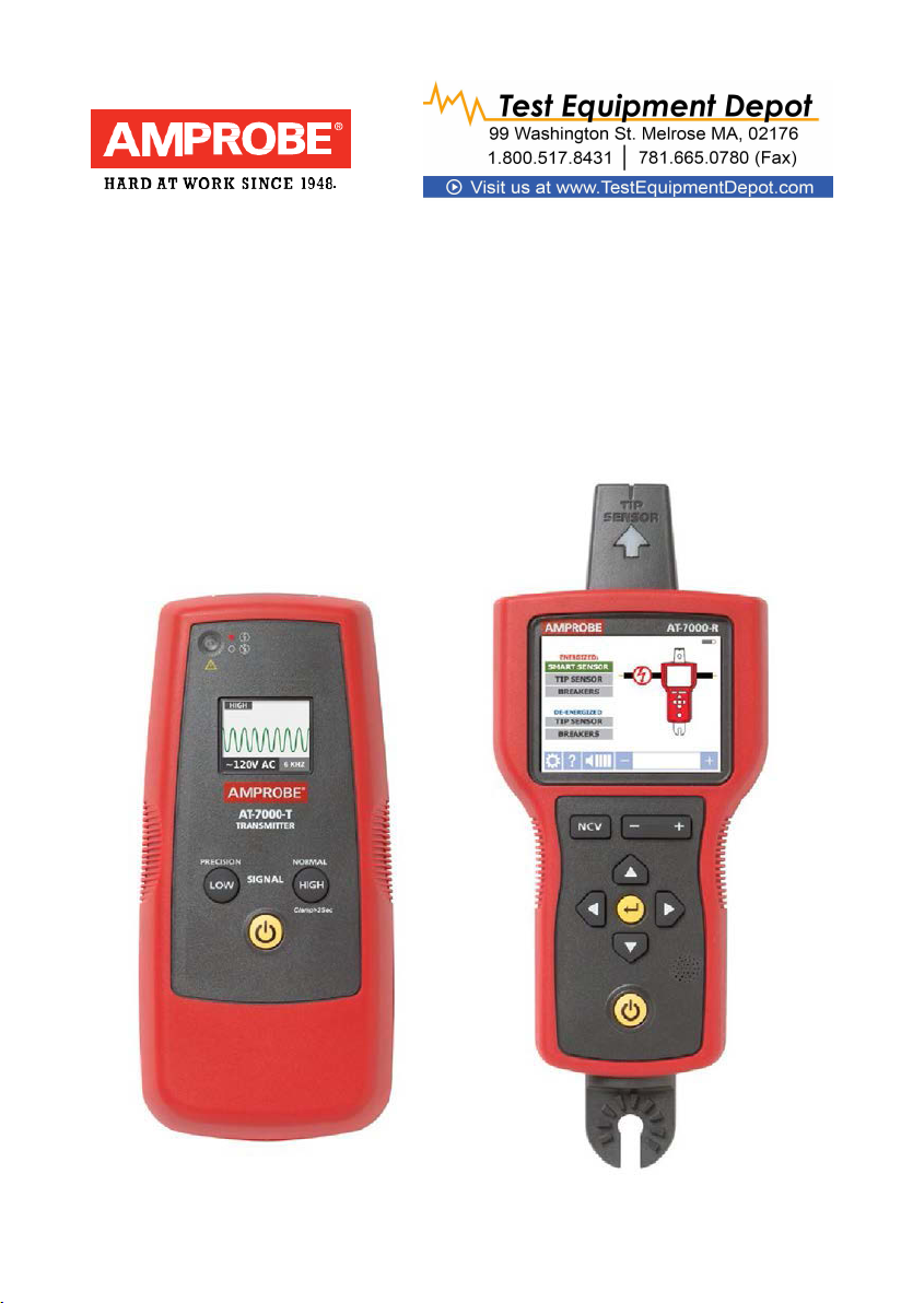
AT-7000
Advanced Wire Tracers
AT-7020
AT-7030
User Manual
For detailed specifications and ordering info go to www.TestEquipmentDepot.com
Page 2

AT-7000
English
Advanced Wire Tracer
AT-7020 AT-7030
User Manual
Page 3

Limited Warranty and Limitation of Liability
Your Amprobe product will be free from defects in material and workmanship for 1 year from
the date of purchase. This warranty does not cover fuses, disposable batteries or damage from
accident, neglect, misuse, alteration, contamination, or abnormal conditions of operation or
handling. Resellers are not authorized to extend any other warranty on Amprobe’s behalf.
To obt ain ser vic e during the warranty period, return the product with proof of purchase to an
authorized Amprobe Test Tools Service Center or to an Ampr obe dealer or distributor. See
Rep air S ect ion f or details. THIS W ARRANTY IS YO UR ONLY REMEDY. ALL OTHER W ARRANTIES
- WHETHER EXPRESS, IMPLIED OR STAUTORY - INCLUDING IMPLIED WARRANTIES OF
FITNESS FOR A PARTICULAR PURPOSE OR MERCHANTABILITY, ARE HEREBY DISCLAIMED.
MANUFACTURER SHALL NOT BE LIABLE FOR ANY SPECIAL, INDIRECT, INCIDENTAL OR
CONSEQUEN TIAL DAMAGES OR LOSSES, ARISING FROM ANY CAUSE OR THEORY. Since some
states or countries do not allow the exclusion or limitation of an implied warranty or of
incidental or cons equential damages, this limitation of liability may not apply to you.
Repair
All Amprobe tools returned for warranty or non-warranty repair or for calibration should
be accompanied by the following: your name, company’s name, address, telephone number,
and proof of purchase. Additionally, please include a brief description of the problem or
the service requested and include the test leads with the meter. Non-warranty repair or
replacement charges should be remitted in the form of a check, a money order, credit card
with expiration date, or a purchase order made payable to Amprobe.
In-warranty Repairs and Replacement – All Countries
Please read the warranty statement and check your battery before requesting repair. During
the warranty period, any defective test tool can be returned to your Amprobe distributor for
an exchange for the same or like product.
Non-warranty Repairs and Replacement – United States and Canada
Non-warranty repairs in the United States and Canada should be sent to an Amprobe Service
Center. Call Amprobe or inquire at your point of purchase for current repair and replacement
rates.
Page 4

1
AT-700
CONT ENTS
1.
PRECAUTIONS AND SAFETY MEASURES
2.
KIT COMPONENTS
2.1
AT-7000-R Receiver ........................................................................................................... 6
2.2
AT-7000-T Tr ansmitter ...................................................................................................... 8
2.3
TL-7000 Test Lead & Accessory Kit .................................................................................. 9
2.4
SC-7000 Signal Clamp (AT-7030 Kit) ............................................................................... 10
2.5
BR-7000-T Signal Booster Rechargeable Battery Pack (AT-7030 Kit)........................... 10
3.
MAIN APPLICATIONS
3.1
Trac ing Energized W ires
•
SMART SENSOR ............................................................................................................................
•
TIP SENSOR Energized ..................................................................................................
3.2
Trac ing De-Energized W ires
•
TIP SENSOR De-Energized ............................................................................................
3.3
Identifying Breakers and Fuses
•
BREAKER Energized (Energized Circuits) .................................................................... 18
•
BREAKER De-Energized (De-Energized Circuits) ........................................................ 20
3.4
Non-Contact V oltage Mode (NCV) .................................................................................. 21
4. SPECIAL APPLICATIONS
4.1
GFCI-Protected Circuit Wire Tracing ............................................................................... 22
4.2
Finding Breaks/Opens ...................................................................................................... 22
4.3
Finding S hor ts ................................................................................................................... 23
4.4
Tracing Wires in Metal Conduit ...................................................................................... 24
4.5
Tracing Non-Metallic Pipes and Conduits ...................................................................... 24
4.6
Tracing Shielded W ir es..................................................................................................... 24
4.7
Trac ing Undergr ound Wires ............................................................................................ 25
4.8
Trac ing Low Voltage W ires and Dat a Cables ................................................................. 25
4.9
Sorting Bundled Wires ..................................................................................................... 25
4.10
No Acc ess to Bare Conductors (Signal Clamp).............................................................. 26
4.11
Locating Loads (Signal Clamp) ....................................................................................... 27
5.
MAINTENANCE - BATTERY AND FUSE REPLACEMENT
6. SPECIFICATIONS
................................................................................................................
............................................................................................................
.....................................................................................................................
.....................................................................................................................................
.......................................................................
..............................................
0 Series
2
5
11
12
14
16
22
28
31
Page 5

2
1.
Precautions and safety measures
General
For your own safety and to avoid damage to the instrument we suggest you to follow the
procedures listed b elow:
NOTE: Before and during measurements be diligent to follow the instructions.
•
Make sure that the electrical instrument is operating properly before us e.
•
Before attaching any of the conductors, make sure that the voltage present in the
conductor is in the range of the instrument.
•
Keep the instruments in their carrying case when not in use.
•
If the transmitter or receiver will not be used for a long time, remove the batteries to
prevent leakage in the instruments.
•
Use A mpr obe approved c ables and accessories only.
Safety precautions
•
In many instances, you will be working with dangerous level of voltage and/or current,
therefore, it is important that you avoid direct contact with any uninsulated, current
carrying surfaces. Wear appropriate insulated gloves and protective clothing in
hazardous voltage areas
•
Do not measure voltage or current in wet or damp or dusty places
•
Do not measure in presence of gas, explosive m ater ials or combustibles
•
Do not touch the c ircuit under test if no measurement is being taken
•
Do not touch exposed metal parts, unused terminals, circuits and so on
•
Do not use the instrument if it seems to be malfunctioning (i.e. if you notice
def orm ations, breaks, leakage of substances, and absence of mes sag es on the display
and so on.)
Safety information
The product com plies with:
•
UL/IEC/EN 61010-1, CAN/CSA C22.2 No. 61010-1, Pollution Degree 2, Measurement
category IV 600 V (AT-7000-R); Category IV 300V MAX (AT-7000-T)
• IEC/EN 61010
• IEC/EN 61010-2-032
•
IEC/EN 61010-031 (test leads)
•
EMC IEC/EN 61326-1
Measurement Category III (CAT III)
to the distribution part of the building’s low-voltage MAINS installation. This part of the
installation is expected to have a minimum of two levels of over-current protective devices
between the transformer and possible connecting points
-2-033
is applicable to test and measuring circuits connected
Measurement Category IV (CAT IV)
utility power source for a given building or between the building power supply and the
main distribution board. Such equipment may include electricity tariff meters and primary
over current protection devices.
CENELEC Directives
The instruments conform to CENELEC Low-voltage directive 2006/95/EC and Electromagnetic
compatibility directive 2004/108/EC.
is for circuits that are directly connected to the primary
Page 6

3
1.
Precautions and safety measures
�Warnings: Read Before Using
To avoid pos sible el ectric s hoc k or pers onal injury:
•
Use the Meter only as specified in this manual or the protection provided by the
instrument might be impaired.
•
Avoid working alone so assistance can be r end ered.
•
Never measure ac current while the test leads are inserted into the input jacks.
•
Do n ot us e th e Meter in wet or damp environments.
•
Do not use the Meter if it appears damaged. Inspect the Meter before use. Look
for cracks or missing plastic. Pay particular attention to the insulation around the
connectors.
•
Inspect the test leads before use. Do not use them if insulation is damaged or metal is
exposed.
•
Check the test leads for continuity. Replace damaged test leads before using the Meter.
•
Have the Meter serviced only by qualified service personnel.
•
Use extreme caution when working around bar e conductors or bus bars. Contact with
the conductor could result in electric shock.
•
Do not hold the Meter anywhere beyond the tactile barrier.
•
Do not apply more than the rated voltage, as marked on the Meter, between the
terminals or between any terminal and earth ground.
•
Remove test leads from the Meter bef ore opening the Meter c ase or batter y cover.
•
Never operate the Meter with the battery cover removed or the case open.
•
Never remove the battery cover or open the case of the Meter without first removing
the test leads from a live conductor.
•
Use caution when working with volt ages above 30 V ac rms, 42 V ac peak, or 60 V dc.
These volt ages pos e a sh ock hazard.
•
Do not attempt to measure any voltage that might exceed the maximum range of the
Meter.
•
Use the prop er terminals, function, and range for your measurements.
•
Do not operate the Meter around explosive gas, vapor, or dust.
•
When using probes, keep fingers behind the finger guards.
•
When making electrical connections, connect the common test lead bef ore
connecting the live test lead; when disconnecting, disconnect the live test lead before
disconnecting the common test lead.
•
To avoid false readings that can lead to electrical shock and injury, replace the battery
as s oon as the low battery indicator appears. Check Meter op eration on a know n
source befor e and after us e.
•
When servicing, use only specified user serviceable replacement parts.
•
Adhere to local and national safety codes. Individual protective equipment must
be used to prevent shock and arc blast injury where hazardous live conductors are
exposed.
•
Only use the test lead provided with the Meter or UL Listed Probe Assembly rated CAT
IV 600V or better.
•
Do not use HOT STICK to oper ate the AT-7000-R R eceiver around voltage more than 600V
Page 7
4
1. Precautions and safety measures
Automatic mode
�
T
reinforced insulation.
J
CAT IV
B
F
)
P
=
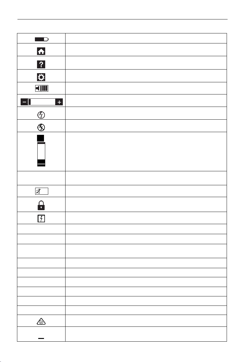
Symbols used in this product
Battery status – Displays the remaining battery charge
Home – R eturn to home screen when s elected
Help – Enters to the help mode when selected
Settings – Enters to the settings menu when selected
Volume– Displays the volume in four levels
Sensitivity indicator – Displays the sensitivity level from 1 to 10.
Icon indicating energized sys te m
Icon indicating de-energized system
99
Signal strength indicator – Shows the strength of the signal
from 0 to 99
SI GNA L
MAN/AUTO
Shows whether the sensitivity adjustment is in Manual or
Indicates the volume is muted.
Lock indicates if the Auto sensitivity lock is active
(Only in Auto sensitivity mode)
Application and removal from hazardous live conductors permitted
Caution! Risk of elec tric shock.
Caution! Refer to the explanation in this Manual.
The equipment is protected by double insulation or
Earth (Gr ound).
Overvoltage up to Category IV 300V (transient protection up to 6kV)
Alternating Current (AC).
Direct Current (DC).
Conforms t o relevant North Americ an S afet y St and ards .
Complies with European Directives.
Conforms to relevant Australian standards.
Do not dispose of this product as unsorted municipal waste. Contact
a qualified rec ycler.
Page 8
1.
AT-7000-T TRANSMITTER
Precautions and safety measures
This manual contains information and warnings that must be followed for operating the
tester safely and maintaining the tester in a safe operating condition. If the tester is used in
a manner not specified b y th e manufacturer, the protection provided by the tester may be
impaired. This tester meets water and dust protection IP40 per IEC60529 Ed 2.1 (2001). Do
not use in rainfall! The tester is double insulated for protection per EN61010-1:2010 3rd Ed
to CAT IV 600V. (AT-7000-R) and CAT IV 300V MAX (AT-7000-T)
CAUTION:
Patient areas of a health care facility. Make the ground connection first and disconnect it
last.
2.
Kit comPonents
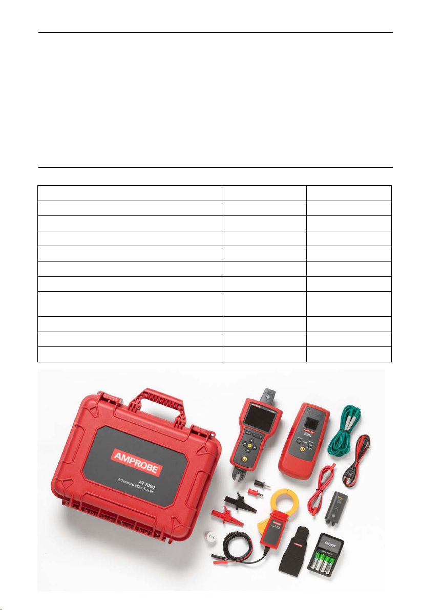
Your shipping box should include:
AT-7000-R RECEIVE R
TL-7000 TEST LEAD AND ACCESSORY KIT
CC-7000 HARD CARRYING CASE
USER MANUAL
BR-7000-T LI-ION RECHARGEABLE BATTERY
BR-7000-R WITH 4AA RECHARGEABLE
BATTERIES
SC-7000 SIGNAL CLAMP
HS-1 MAGNETIC HANGER
1.5 V AA (IEC R 6) BATTERY
Do not connect the Transmitter to a separate ground in Electrically Susceptible
AT-7020 KIT AT-7030 KIT
1 1
1 1
1 1
1 1
1 1
- 1
- 1
- 1
- 1
10 -
5
Page 9
6
2.
Kit comPonents
2.1 AT-7000-R Receiver
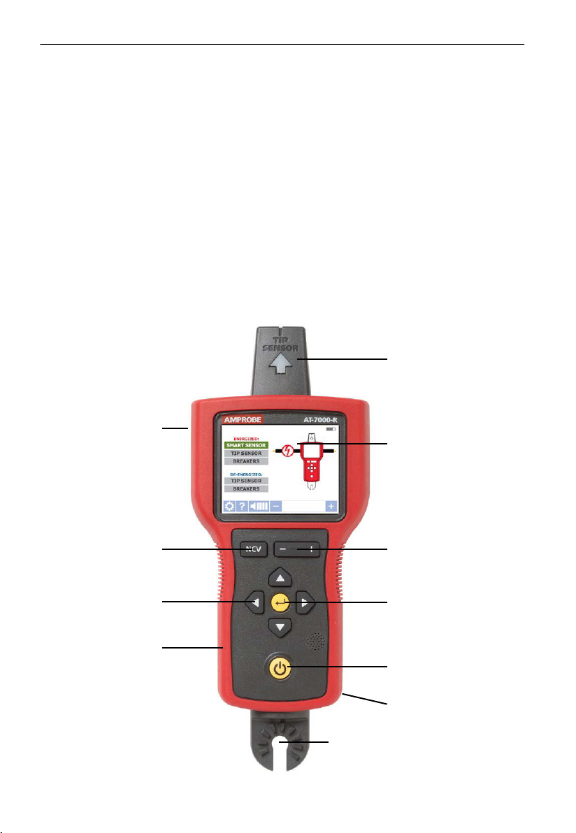
Th e AT-7000-R Receiver detects the signal generated by t he AT-7000-T transmitter along wires
using either the TIP SENSOR or SMART SENSOR and displays this inf orm ation on the full color TFT
LCD display.
Active tracing using a signal generated by the AT-7000-T Transmitter
The SMART SENSOR works with a 6 kHz signal generated along energized wires (above 30V
AC/DC) and provides an indication of the wire position and direc tion rel ative to the receiver.
The SMART SENSOR is not designed to work on de-energized systems; for that application
the TIP SENSOR should be used in de-energized mod e.
The TIP SENSOR may be used on either energized or de-energized wires and can be used for
general tracing, tracing in tight spaces, locating breakers, pinpointing wires in bundles or in
junction boxes. The TIP SENSOR mode will pinpoint the wire location with both an audible
and visual indication of detected signal strength, but unlike SMART SENSOR mode it will not
provide wire direction or orientation.
Note: The receiver will NOT detect signals from the wire through metal conduit or shielded
cable. Refer to Special Applications, section 4.4 “Tracing Wires In M etal Conduit” for
alternative tracing methods.
SMART SENSOR
(Back side)
TIP SENSOR
LCD DISPLAY
Full c olor T FT display
NCV BUTTON
Non-Contac t
oltage mode
V
NAVIGATION KEYS
RUBBER OVER
MOLDED ENCLOSURE
4-WAY
HOT STICK ATTACHMENT POINT
(Do not use for voltage higher
than 600V)
Figure 1: Overview of AT-7000-R Receiver
SENSITIVITY ADJUSTMENT
BUTTON (-/+)
ENTER BUTTON
Sel ects the functions
POWER BUTTON
Turns unit On / Off
BATTERY COMPARTMENT
(Back side)
Page 10
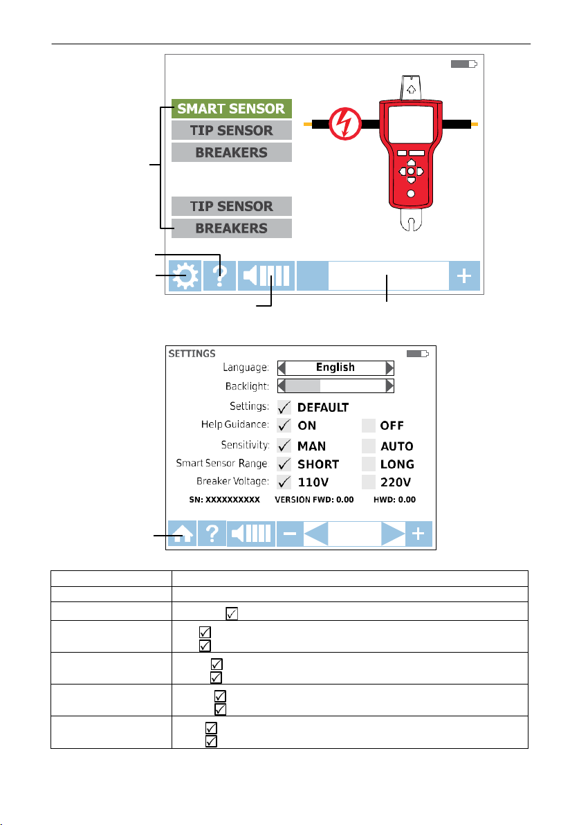
7
DE-ENERGIZED:
2. Kit comPonents
Language
English, French, German, S panish, Italian
Backlight
25%, 50%, 75%, 100%
DEFAULT
: Res tor e def ault settings
Help Guidance
OFF
: Device will start without guidance
Sensitivity*
AUTO : Auto sensitivity adjustment
LONG
: For wire detection between 3 and 20 feet
220V
: For 220V to 240V sys tems
Main applications
Help guide
Setting menu
ENERGIZED:
Buzzer volume adjust ment Sensitivity adjustment
Home menu
Setting
Smart Sensor Range
Figure 1a: Overview of all elements on home screen
Figure 1b: Overview of all elements on the setting menu
ON : Device will guide you thr ough eac h mode
MAN : Manual sensitivity adjustment (+) and (-) keys
SHORT
: For wire detection up to 3 feet
Breaker Voltage
*Note: The Auto and Manual sensitivity mode can be easily changed by pressing the + and
– key at the same time when the receiver is in a tracing mode. When sensitivity mode is set
110V
: For 110V to 120V sys tems
Page 11
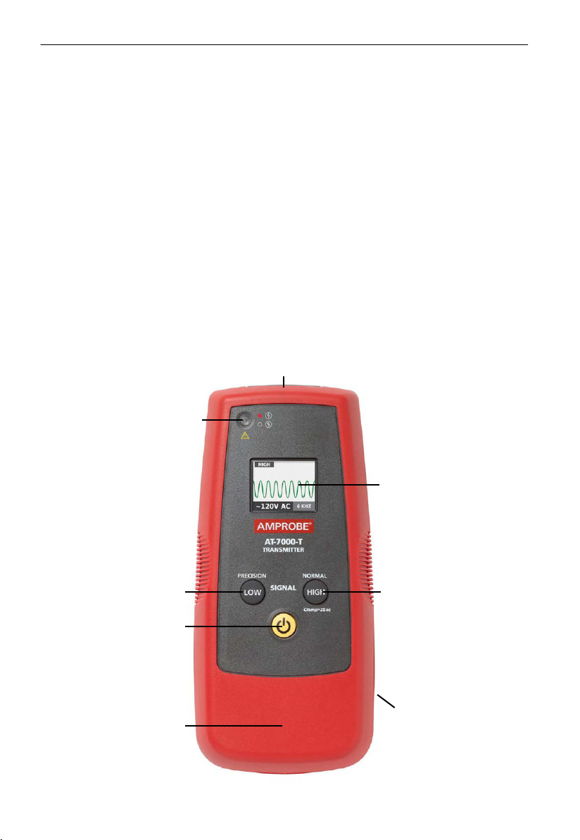
9
2. Kit comPonents
2.2 AT-7000-T Transmitter
The AT-7000-T Transmitter works on energized and de-energized circuits up to 300V AC/DC
in C ateg ory I-IV electrical environments.
The transmitter will measure the line voltage and display it on the transmitter’s color
TFT LCD display screen. Based on detected voltage it will automatically switch to either
energized mode (30 to 300V AC/DC) or de-energized mode (0 to 30V AC/DC). The energized
mode uses a lower transmission frequency (6kHz) than de-energized mode (33 kHz) to
reduce signal coupling with nearby metallic objects and improve results. If the circuit is
energized the red LED in the upper left corner of the AT-7000-T transmitter will light.
IMPORTANT! Note that the red LED light will turn on when connected to an energized
circuit. Select the correct energized or de-energized mode on the AT-7000-R receiver when
choosing your tracing mode.
Energized mode: In energized mode the transmitter draws very low current from the
energized circuit and generates a 6.25 kHz signal. This is very important feature of the
AT-7000-T, since drawing current does not inject any signal that would harm sensitive
equipment connected to the circuit. The signal is also generated in a direct path between
the transmitter and the power source, thus NOT placing a signal onto any branches enabling
wiring tracing directly back to the breaker panel. Please note that due to this feature, the
transmitter has to be connected on the load side of the circuit.
De-energized mode:
circuit. In this mode, since the signal is injected, it w ill travel through all the circuit branches.
It is a high frequency, very low energy signal that will not harm any sensitive equipment
RED LED VOLTAGE INDICATOR
Indicates the transmitter mode
1.
Red: Energized circuit mode
2.
Amber: Overload
3.
OFF: De-en ergized circuit
mode
In de-energized mode the transmitter injects a 32.8 kHz signal onto the
TEST LE ADS CONNECTION JACKS
COLOR TFT LCD DISPLAY
LOW/PRECISION MODE
For prec isi on applications
ON / OFF BUTTON
RUBBER OVERMOLDED
ENCLOSURE
Figure 2: Overview of AT-7000-T Trans mitter
HIGH/NORMAL M ODE
Used f or m ost applications
BATTERY COMPARTMENT
(Back side)
Page 12
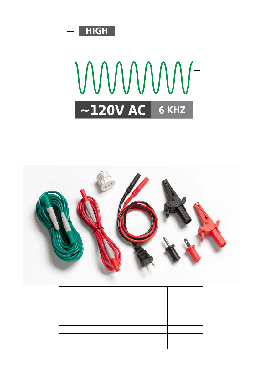
1
2. Kit comPonents
TL-7000
US power cord with banana plugs
1
Tes t lead (red). 6.4 ft. (1.9m)
1
Tes t lead (green), 25 ft. (7.7 m)
1
Alligator clip set (red, black)
1
Plug adaptor – flat pin (red)
1
Plug adaptor – round pin (black)
1
Light socket adaptor
1
Power Mode
Transmission
Frequency &
Amplitude
Detected Voltage
Figure 2a: Overview of AT-7000-T Trans mitter LCD Screen
2.3
TL-7000 Test Lead & Accessory Kit
All AT-7000 kits come with our complete test leads & accessory kit. The kit supports a
wide range of standard and specialty applications and contains test leads and adaptors as
outlined below:
Transmission
Frequency
Page 13
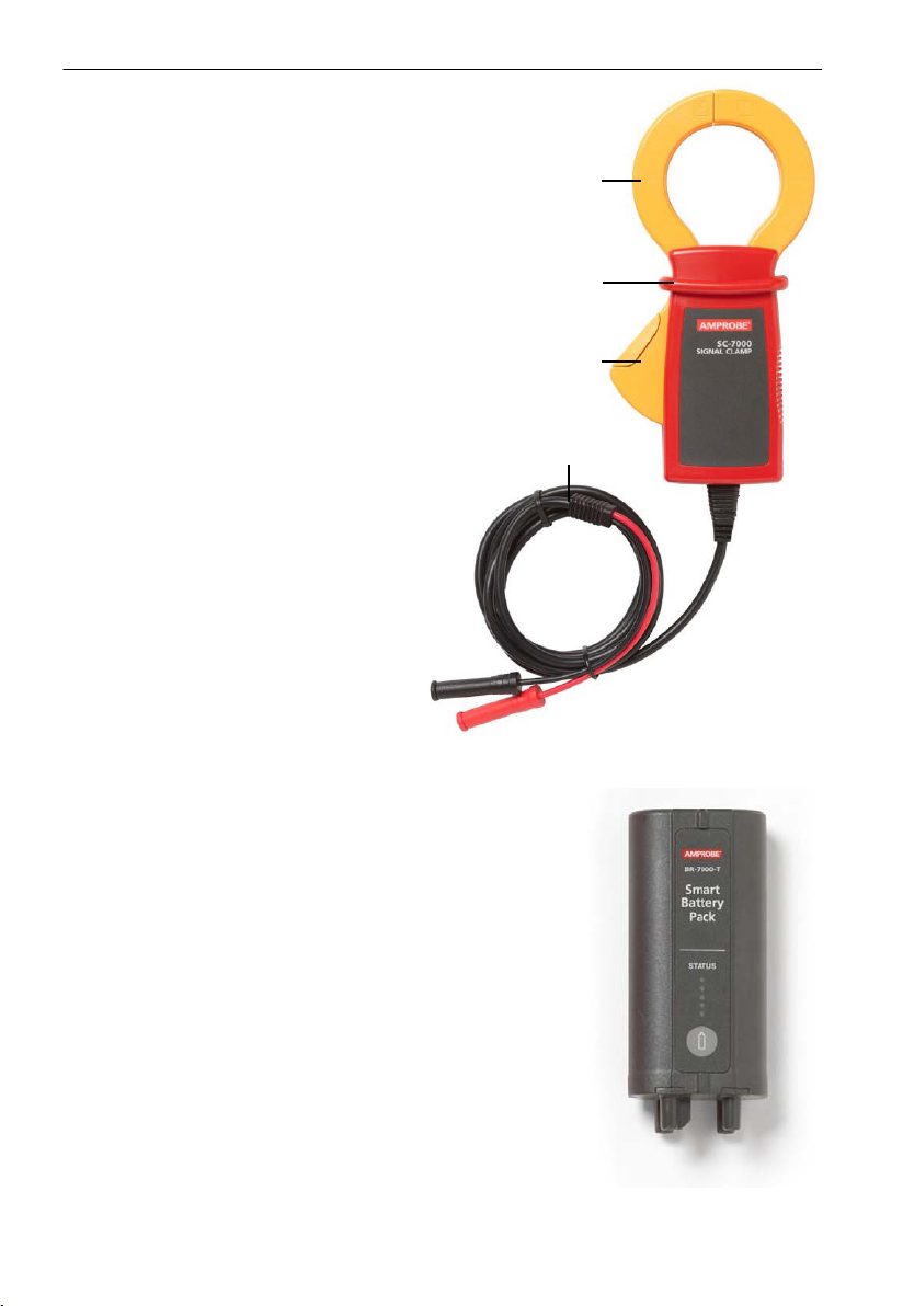
11
JAW HAND GUARD
JAW TRIGGER
INPUT
WITH
2. Kit comPonents
2.4 SC-7000 Signal Clamp
(included with AT-7030, option for AT-7020)
The clamp acc essory is us ed for applications
when th ere is no access to the bar e
conductors. The clamp attachment enables
the AT-7000-T Tr ansmitter to induce a
signal through the insulation into either
energized or de-energized wires. The
signal will travel through the wire in both
directions and into all the branches. This
transmission method will not damage any
sensitive electronic equipment connected to
the circuit.
LEADS
2.5 BR-7000-T Signal Booster Rechargeable Battery Pack
(included with AT-7030, option for AT-7020)
The BR-7000-T Signal B ooster Recharg eab le B attery P ack
provides increased power to the AT-7000-T Trans mitter,
enabling improved wire tracing results in energized, deenergized and clamp modes. This 7.2V, 2.2 Ah Lithium-Ion
(Li-Ion) battery pack automatically begins recharging when
the transmitter is connected to circuits between 90V - 270V.
The outside of the battery features a LED status indicator that
shows the remaining battery charge with the push of a button.
Page 14
1
3.
main aPPLications
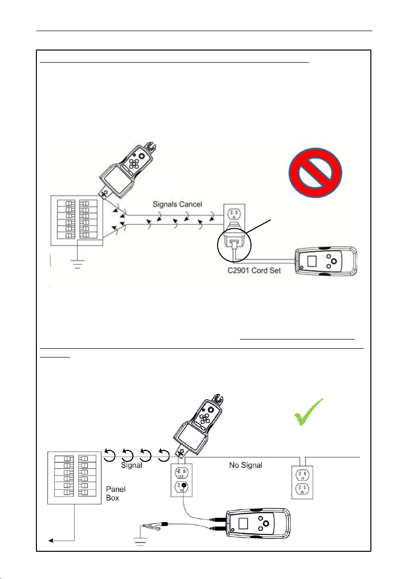
IMPORTANT NOTICE, PLEASE READ BEFORE YOU START TRACING
�
Avoiding signal cancellation problems with a separate ground connection
The signal generated by the transmitter creates an electromagnetic field around the wire.
This field is what is detectable by the receiver. The clearer this signal, the easier it is to tr ace
the wire.
If trans mitter is connected t o two adjacent wires on the same circuit (for example, hot and
neutral wires on a Romax cable), the signal travels in one directions through the firs t wire and
then returns (with opposite direction) through the second one. This causes creation of two
electromagnetic fields around each wire with opposite direction. These opposing fields will
partially or c ompletely canc el eac h oth er out, making wire tr acing difficult if not impossible.
AT-7000-R
Not recommended. T his
wire connection causes
signal cancellation
Figure 3a AT-7000-T
To avoid the cancellation effect, a separate ground connection method should be used.
The red test lead of the transmitter should be connected to the hot wire of the circuit
you wish to trace, and the green lead to a separate ground, such as water pipe, ground
stake, metal grounded structure of the building, or outlet ground connection of an outlet
on a different circuit. It is important to understand that an acceptable separate ground
is NOT the gr oun din g ter minal of any rec eptacle on the same circuit as the wire you wish
to trace. If hot wire is energized and the transmitter is properly connected to
ground,
the maximum signal strength, because the electromagnetic field created around the hot
wire is not being cancelled by a signal on the return path flowing along an adjacent wire
(hot or neutr al) in the opposit e direction, but rather through the sep arate ground circuit.
the red LED on a transmitter will light up. The separate ground connection cr eate
a s epar ate
AT-7000-R
To Tr ans former
Fig
ure 3b
Avoiding signal
cancellation effect
AT-7000-T
Page 15
13
3.
SMART SENSOR
SMAR
T
SENSOR
main aPPLications - smart sensor (energized)
3.1 Tracing Energized Wires
The SMART SENSOR enables easier wire tr acin g by
showing the direction and position of the wire and
is the recommended method for tracing energized
wires (does n ot work on de-energized circuits, use
de-energized
TIP SENSOR f or that application).
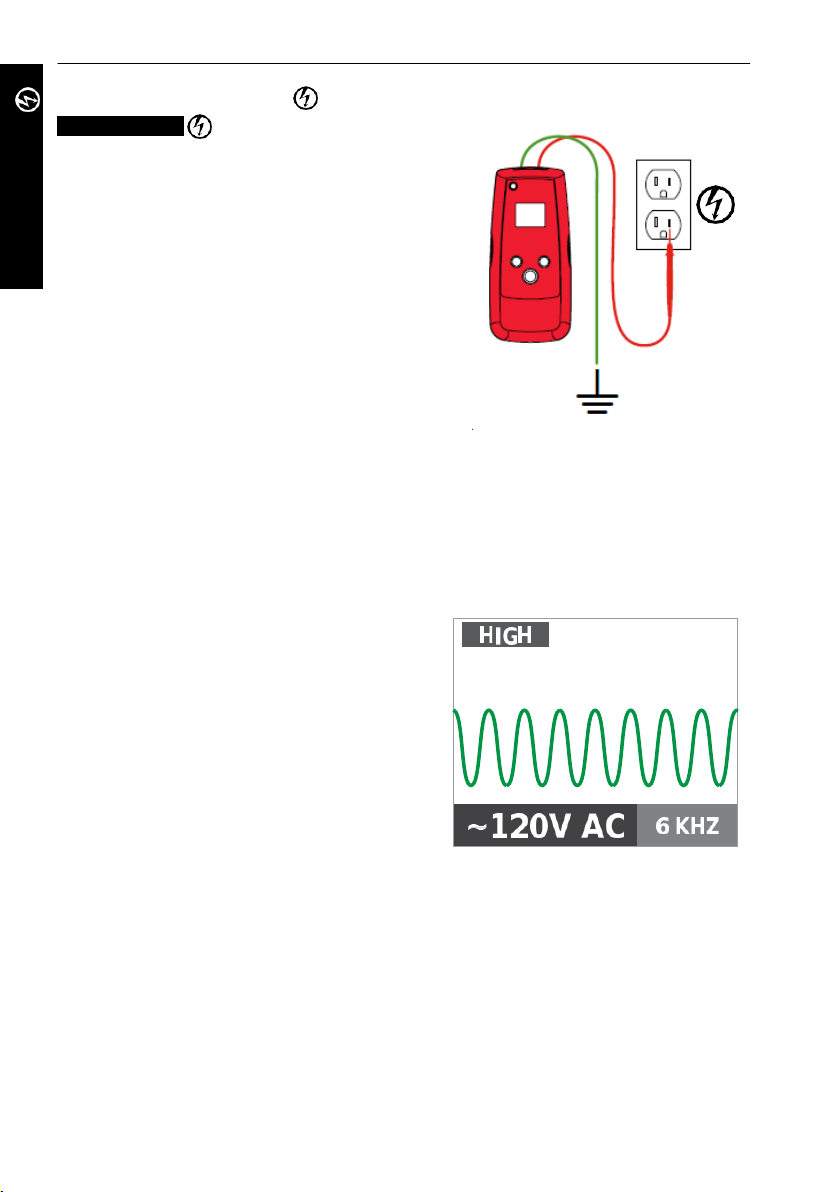
Connecting transmitter t est leads
Connect green and red test leads to the
1.
transmitter (polarity does not matter)
2.
. Connect red lead to energized hot wire (on
the load side of the system). The signal will
ONLY be transmitted between the outlet to
which the transmitter is connected and the
source of power
(see Figure 3a).
3. Con nec t gr een wire to a s eparat e gr ound
(metal building structure, metal water pipe,
or ground wire on a separate circuit).
*Note: Please note that if working with GFCI protected circuits, t his method will trip the
GFCI protection. Refer to Special Applications, section 4.1 “GFCI-Protected Circuit Wire
Tracing” for alternative tracing methods.
Figure 3.1a
Proper c onnection with s epar ate ground
Set up the AT-7000-T Transmitter:
1. Press ON/OFF key to turn on th e
transmitter.
2. Ver ify that the t est leads are prop erly
con nected - the red LED voltage status
should indicator should be on, indicating
that the circuit is energized. If not, make
sure that
•
the circuit is energized
•
the separate ground green wire is
properly grounded. If the ground wire is
not properly grounded the red LED will
ght, even when connected to an
not li
energized circuit.
3. Select HIGH signal mode for most
applications. Screen will appear as shown
in Figure 3.1b.
Note: The LOW signal precision mode can be used to limit the signal level generated by the
transmitter in order to more precisely pinpoint wire location. A lower signal level reduces
coupling to neighboring wires and metal objects and helps to avoid misreading due to
ghost signals. A lower signal also helps to prevent oversaturating the receiver with a
strong sign al that covers a large area. The LOW mode function is rarely used, only for most
demanding precise wire tracing applications.
Transmitter screen showing signal in
HIGH mode with 6kHz frequenc y for
energized circuit
Figure 3.1b
Page 16
13
3.
SMAR
T
SENSOR
main aPPLications - smart sensor (energized)
Using AT-7000-R Receiver
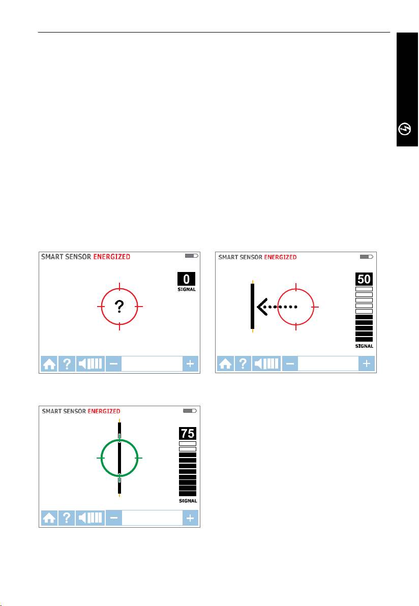
1. Press ‘ON/OFF’ push button to turn on the receiver and wait for the home screen (boot
up time is around 30 seconds).
2. S elec t SM ART SENSOR mode by using the directional arrows to highlight this operating
mode and pressing the yellow ENTER button.
Hold the receiver with the Smart Sensor on the rear of the unit facing the target area.
3.
If the screen flashes a
Sensor closer to the target area until the signal is detected and you see a directional
arrow. If no signal is detected increase the sensitivity using the
rec eiver. (see Figure 3.1c)*
4. Move the Receiver in direction indicated by the arrow on the screen (see Figure 3.1d)
5.
Green target symbol indicates that the Receiver is directly over the wire. If Receiver
will not lock on the wire, decrease sensitivity using the
transmitter to transmit at LOW level (Precision). (see Figure 3.1e)
6. Pres
s ENTER when complete to retur n to Home screen.
*Note: For best results, keep the receiver at least 3 feet from the transmitter and its t est
leads to minimize signal interference and improve wire tracing results. Select the “Long”
Smart Sensor Range in the Settings Menu if working with wires that are greater than 3 feet
deep.
“?”
in a red target then no signal is detected. Move the Smart
“+”
button on the
“-“
on the keypad or set the
Figure 3.1c
No s ign al detec ted
Figure 3.1e
Rec eiver locked on wire
Figure 3.1d
Wire on the left
Page 17
14
3.
TIP SENSOR
TIP
SENSOR
main aPPLications - tiP sensor (energized)
3.1 Tracing Energized Wires
TIP SENSOR mode is used for the following
applications: pinpointing a wire in a bundle,
tracing in c orn ers and confined spac es such as
junction boxes or inside enclosures.
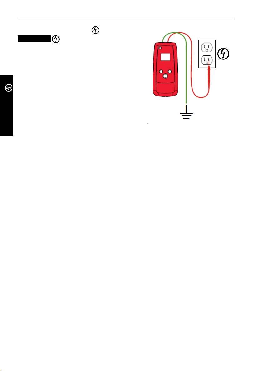
Connecting transmitter t est leads
Connect green and red test leads to the
1.
transmitter (polarity does not matter)
2. Connect red lead to energized hot wire (on
the load side of the system).
The signal will ONLY be transmitted between
the outlet to which the transmitter is
connected and the source of power (see
Figure 3b).
3. Con nec t gr een wire to a s eparat e gr ound
(metal building structure, metal water pipe,
or ground wire on a separate circuit).
*Note: Please note that if working with GFCI protected circuits, t his method will trip the
GFCI protection. Refer to Special Applications, section 4.1 “GFCI-Protected Circuit Wire
Tracing” for alternative tracing methods.
Figure 3.1f
Proper c onnection with s epar ate ground
Set up the AT-7000-T Transmitter:
1. Press ON/OFF key to turn on the transmitter.
2. Verify that the test leads are properly connected - the red LED voltage status should
indicator should be on, indicating that the circuit is energized. If not, make sure th at
•
the circuit is energized
•
the separate ground green wire is properly grounded. If the ground wire is not
properly grounded the red LED will not light, even when connected to an energized
circuit.
3. Sel ec
Note: The LOW signal precision mode can be used to limit the signal level generated by the
transmitter in order to more precisely pinpoint wire location. A lower signal level reduces
coupling to neighboring wires and metal objects and helps to avoid misreading due to
ghost signals. A lower signal also helps to prevent oversaturating the receiver with a
strong sign al that covers a large area. The LOW mode function is rarely used, only for most
demanding precise wire tracing applications.
t HIGH signal mode for most applications. Screen will appear as shown in Figure
3.1b.
Page 18
15
Figure 3.1h
TIP SENSOR ENE RGIZED
75
SIGN AL
30-600V AC/DC
40-400 HZ
3.
TIP
SENSOR
main aPPLications - tiP sensor (energized)
Using AT-7000-R Receiver
1. Press ‘ON/OFF’ push button to turn on the receiver and wait for the home screen (boot
up time is around 30 seconds).
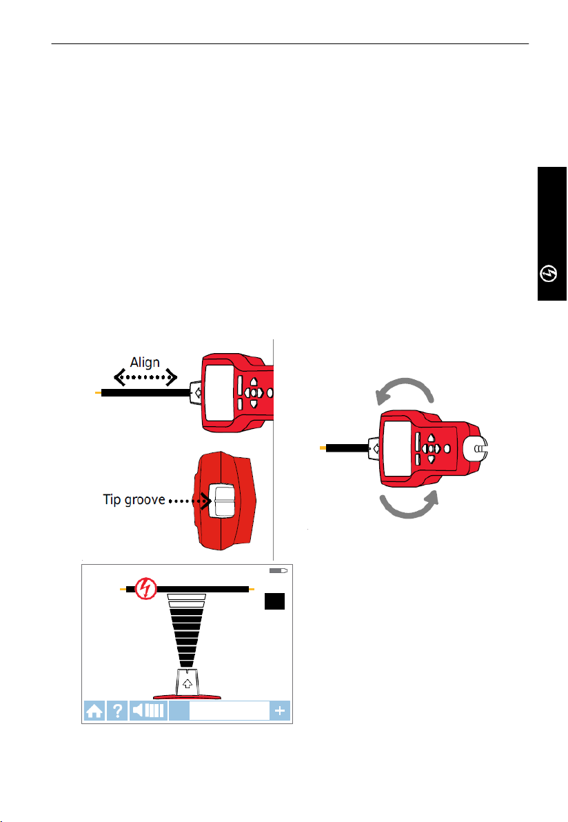
2. S elec t En ergi zed TIP SENSOR mode by using the directional arrows to highlight this
operating mode and pressing the yellow “ENTER” button. Screen as shown in 3.1i will
appear.
Hold the receiver with the Tip Sensor facing the target area.
3.
4.
Scan target area with Tip Sensor to find highest signal level. While tracing, periodically
adjust sensitivity to keep signal strength near 75. Increase or decrease sensitivity
by pr
essing + or – on the keypad. If signal is too strong for precise locating, change
transmitter to LOW mod e.
5.
Receiver Positioning: For best results, align groove on tip sensor with wire direction as
shown. Signal may b
6. T o ve
rify wire direction, periodically rotate receiver 90 degrees. Signal strength will be
highest when wire is aligned with Tip Sens or groove. (see Figure 3.1h)
7. Press ENTER when complete to ret urn to Home screen.
Note: For best results, keep the receiver at least 3 feet from the transmitter and its test
leads to minimize signal interference and improve wire tracing results.
e lost if not properly aligned. (see Figure 3.1g)
Figure 3.1g
Figure 3.1i
Receiver showing signal detected in
Energized TIP SENSOR mode
Page 19
16
3.
TIP SENSOR
TIP
SENSOR
main aPPLications - tiP sensor (de-energized)
3.2 Tracing De-energized Wires
De-energized TIP SENSOR mode is used for gener al
wire tracing, pinpointing wires in bundles, tracing
in tight corners and confined spaces such as
junction boxes or inside enclosures.
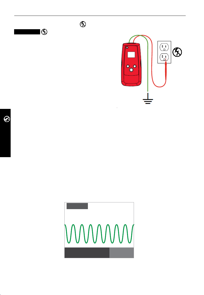
Connecting transmitter t est leads
1.
Connect green and red test leads to the
transmitter (polarity does not matter)
2. Connect red lead to de-energized hot wire
(on the load side of the system).
In de-energized mode the signal will be
injected to ALL branches of the circuit, not
just between the outlet and the breaker as in
energized modes.
3. Con nec t gr een wire to a s eparat e gr ound
(metal building structure, metal water pipe,
or ground wire on a separate circuit).
Set up the AT-7000-T Transmitter:
1. Press ON/OFF key to turn on the transmitter.
2. The red LED voltage status should indicator should be off, indicating that the circuit is
de-energized. If LED is on, disconnect power to the circuit.
3. S elec t HIGH signal mode for most applications. Screen will appear as shown in Figure
3.2b
Note: The LOW signal precision mode can be used to limit the signal level generated by the
transmitter in order to more precisely pinpoint wire location. A lower signal level reduces
coupling to neighboring wires and metal objects and helps to avoid misreading due to
ghost signals. A lower signal also helps to prevent oversaturating the receiver with a
strong sign al that covers a large area. The LOW mode function is rarely used, only for most
demanding precise wire tracing applications.
Figure 3.2a
Proper c onnection with s epar ate ground
HIGH
0V DC
Figure 3.2b
33 KHZ
Page 20
17
3.
TIP SE NSOR DE-ENERGIZED
75
SIGNAL
0-30V AC/DC
TIP
SENSOR
main aPPLications - tiP sensor (de-energized)
Using AT-7000-R Receiver
1. Press ‘ON/OFF’ push button to turn on the receiver and wait for the home screen (boot
up time is around 30 seconds).
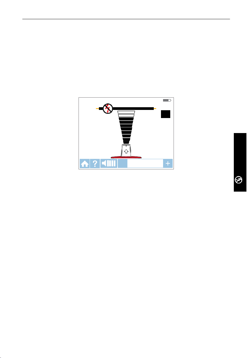
2. S elec t De-Energized TIP SENSOR mode by using the directional arrows to highlight this
operating mode and pressing the yellow “ENTER” button. Screen will appear as shown
in Figure 3.2c
Hold the receiver with the Tip Sensor facing the target area.*
3.
4.
Scan target area with Tip Sensor to find highest signal level. While tracing, periodically
adjust sensitivity to keep signal strength near 75. Increase or decrease sensitivity
by pr
essing + or – on the keypad. If signal is too strong for precise locating, change
transmitter to LOW mod e.
5. Press ENTER when complete to ret urn to Home screen.
*Note: For best results, keep the receiver at least 3 feet from the transmitter and its test
leads to minimize signal interference and improve wire tracing results.
De-energized mode uses a different antenna in the Tip Sensor than in energized mode.
Specific alignment of the Tip Sensor groov e to the wire is not required. De-energized wire
tracing results ar e based only on how close the Tip Sensor is to the wire.
Figure 3.2c
Page 21
18
BREAKERS
3.
BREAKERS
main aPPLications - breaKers (energized)
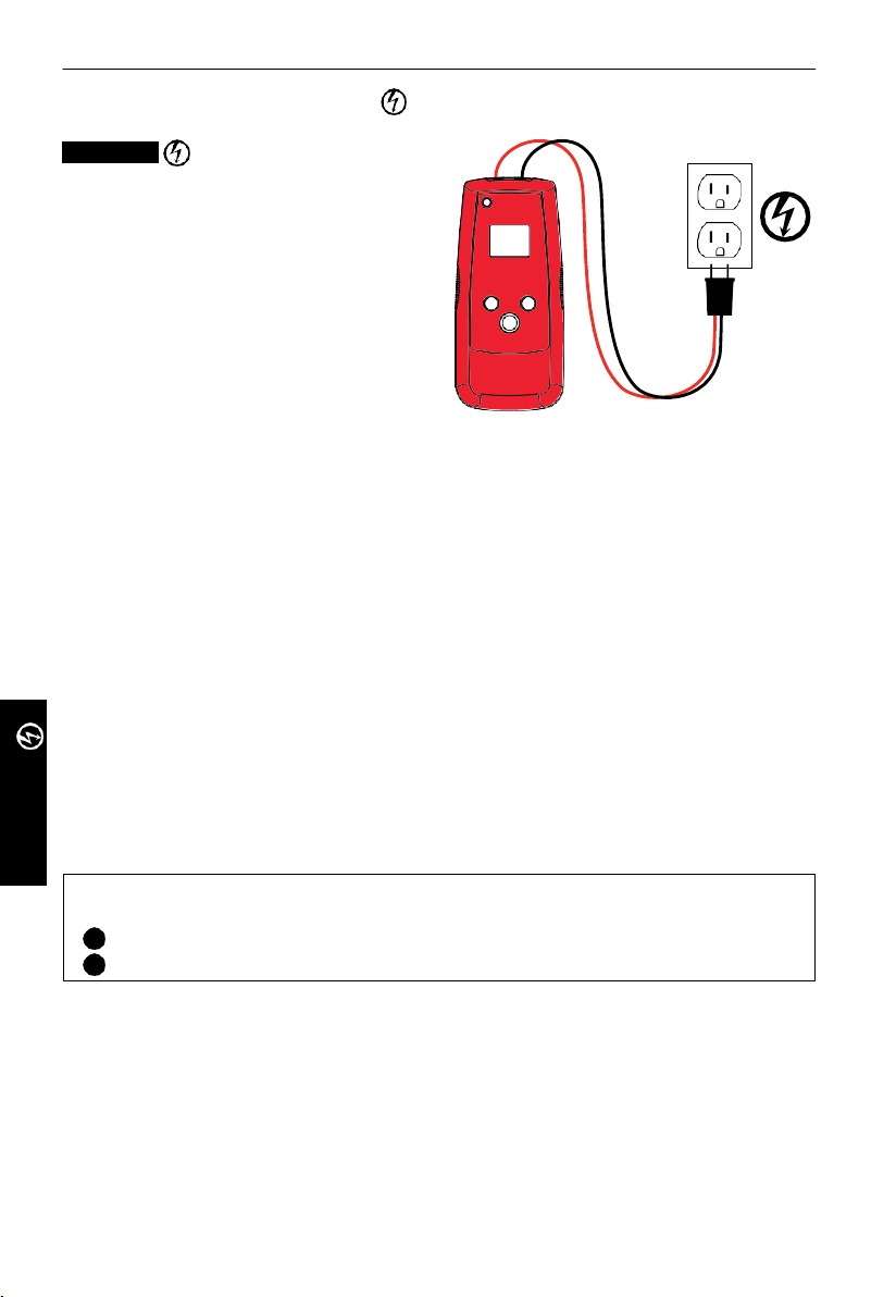
3.3 Identifying Breakers and Fuses
Energized breaker locating
Connecting transmitter t est leads
1. Use test leads with standard plug
connection for r eceptac les and bl ack and
red test leads with alligator clips when
connecting to wir es.
2. Plug test leads into Trans mitter. Polarity
is n ot imp ortant.
Connect plug to outlet, or if using test
3.
leads connect them to hot and neutral
wires.
Note: For breaker locating, a simplified
direct connection to hot and neutral wires
can be used becau se these wires are
separated at the breaker panel. There is no
risk of signal cancellation effect if wires are at least a few inches (centimeters) away from
each other. However the separate ground connection as shown in Energized TIP SENSOR
should be used for superior results specifically if wires need to be traced in addition to
breaker identification.
The simplified direct connection to hot and neutral wire will NOT trip the GFCI circuit.
Figure 3.3a
Set up the AT-7000-T Transmitter:
1. Press ON/OFF key to turn on the transmitter.
2. Verify that the test leads are properly connected - th e red LED vol tag e stat us indicator
should be on, indicating that the circuit is energized. If not, make sure that
•
the circuit is energized
•
the test leads are fully plugged into the transmitter
•
ground green wire is properly grounded (if using separate ground connection
method). If the ground wire is not properly grounded the red LED will not light, even
when connected to an energized circuit.
ect HIGH signal mode for breaker tracing.
3. Sel
Receiver Process Overview
Tracing breakers is a two-step p roc ess :
1
SCAN - Sc an each breaker for one secon d. The receiver will record tracing signal levels.
2
LOCAT E - The receiver will indic ate the single breaker wit h the strongest recorded signal.
Using AT-7000-R Receiver
1. Press ‘ON/OFF’ push button to turn on the receiver and wait for the home screen (boot
up time is around 30 seconds).
2. Sel ect Energized BRE AKERS mode by using the directional arrows to highlight this
operating mode and pressing the yellow “ENTER” button.
Page 22
19
1 1 2
Figure 3.3d
3.
BREAKERS
main aPPLications - breaKers (energized)
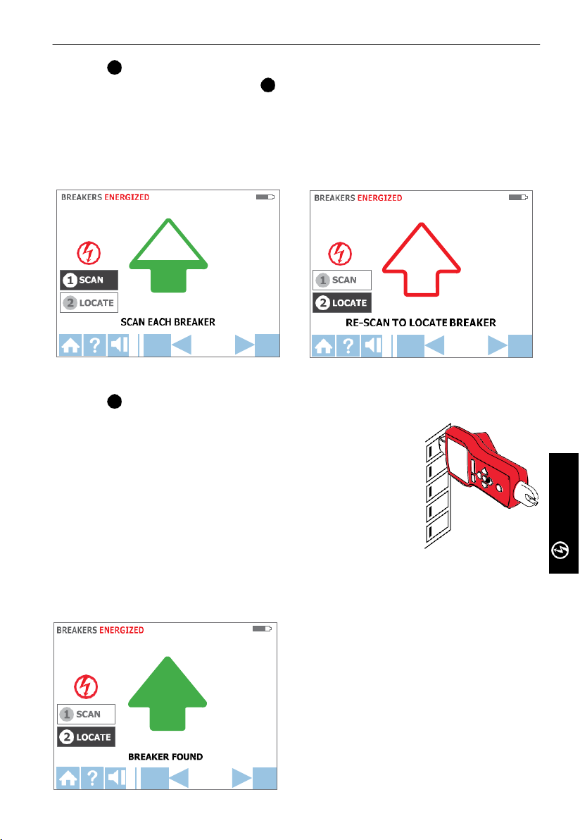
Step 1 - SCAN:
1.
The unit will automatically start in
2.
Scan each breaker for a half second by touching it with the Tip Sensor. Make sure the
groove on the Tip Sensor is parallel to the breaker lengthwise (See Figure 3.3d)
To assure sufficient time between the scans, wait for active green arrow and audible
3.
alert (2-beeps) before moving to the next breaker.
4. Scan all breakers – the order of scanning does not matt er. You can sc an breakers
multiple times. The receiver is recording the highest detected signal.
SCAN mode as shown in Figure 3.3b.
SCAN mode – receiver scanning breakers
Step 2 - LOCATE
1.
Select LOCATE mode by using the directional arrows to
highlight this oper
“ENTER” button. (See figure 3.3c)
2. Rescan each breaker by touching each with the Tip Sensor
for a half second. Active red arr ow indicates scanning pr ocess
(see Figure 3.3c). Make sure the groove on the Tip Sensor is
parallel to the breaker lengthwise.(See Figure 3.3d)
3. Rescan all breakers until solid green arrow and audible alert
(continuous beep) indicates that the correct breaker was
found. (See figure 3.3e)
4. Press ENTER when complete to return to Home screen.
Usage Tip: The accuracy of breaker identification results can be verified by switching the
receiver to Energized TIP SENSOR mode and checking that that the signal level of the
breaker identified by the receiver is the highest among all breakers.
Figure 3.3b
LOCATE mode – receiver checking breakers
ating mode and pressing the yellow
LOCATE mode – receiver identified breaker
Figure 3.3c
Figure 3.3e
Page 23
20
BREAKERS
1
3.
BREAKERS
main aPPLications - breaKers (de-energized)
3.3 Identifying De-Energized Breakers and Fuses
De-Energized breaker locating
Connecting transmitter t est leads
1. Use test leads with standard plug
connection for r eceptac les and bl ack and
red test leads with alligator clips when
connecting to wir es.
2. Plug test leads into Transmitter. Polarity
is n ot imp ortant.
3.
Connect plug to outlet, or if using test
leads connect them to hot and neutral
wires.*
*
The separate ground connection as shown
in De-Energized TIP SENSOR should be used
for superior results specifically if wires
need to be traced in addition to breaker
identification.
Set up the AT-7000-T Transmitter:
1. Press ON/OFF key to turn on the transmitter.
2. The red LED voltage status should indicator should be off, indicating that the circuit is
de-energized. If LED is on, disconnect power to the circuit.
3. Select HIGH signal mode for breaker tr acing.
Figure 3.3f
Receiver Process Overview
Tracing breakers is a two-step p roc ess :
1
SCAN - Sc an each breaker for one secon d. The receiver will record tracing signal levels.
2
LOCAT E - The receiver will indic ate the single breaker wit h the strongest recorded signal.
Using AT-7000-R Recei ver
1. Press ‘ON/OFF’ push button to turn on the receiver and wait for the home screen (boot
up time is around 30 seconds).
2. Select De-Energized BREAKERS mode by using the directional arrows to highlight this
operating mode and pressing the yellow “ENTER” button.
3. Step 1 - SCAN
a)
Select SCAN mode by using the directional arrows to highlight this operating mode
and pressing the yellow “ENTER” button.
b)
Scan each breaker for a half second by touching it with the Tip Sensor. Make sure the
groove on the Tip Sensor is parallel to the breaker lengthwise
c)
To assure sufficient time between the scans, wait for active green arrow and audible
alert (2-beeps) before moving to the next breaker.
d)
Scan all breakers – the ord er of scanning d oes not matter . You can scan breakers
multiple times. The receiver is recording the highest detected signal.
Page 24
21
2
3. main aPPLications - breaKers (de-energized)
NCV
MODE
4. Step 2 - LOCATE
a)
Select LOCATE mode by using the directional arrows to highlight this operating mode
and pressing the yellow “ENTER” button.
b)
Scan each breaker again for a half second each by touching it with the Tip Sensor.
Active red arrow indicates scanning process. Make sure the groove on the Tip Sensor is
parallel to the breaker lengthwise.
c)
Rescan all breakers until solid green arrow and audible alert (continuous beep)
indicates that the correct breaker was found.
d)
Pres s ENTER when complete to return to Home screen.
Usage Tip: The accuracy of breaker location can be verified by switching the receiver to
De-Energized TIP SENSOR mode, and checking that that the signal level of the breaker
identified by the receiver is the highest among all breakers.
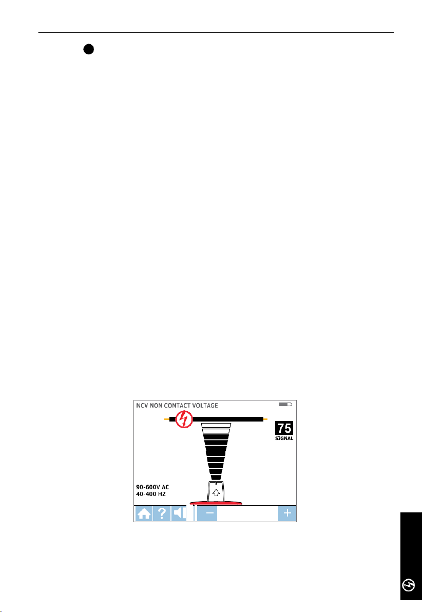
NCV Mode
3.4
The NCV (N on-Contact Voltage) mode is used to verify that the wire is energized. This
method does not require the use of the transmitter. The receiver will detect an energized
cable if the voltage is between 90V and 600V AC and between 40 and 400Hz. No curr ent
flow is n eces sar y.
Note: For safety, before working with wires, always verify that they are de-energized with
an additional tester.
NCV mode operation:
1. Press ‘ON/OFF’ push button to turn on the receiver and wait for the home screen (boot
up time is around 30 seconds).
2. Press ‘NCV’ push butt on to select the Non-Contact V oltage mode.
3.
Hold the receiver with the Tip Sensor against the wire.
4. For
precise pinpointing of hot wire versus neutral wire, increase or decrease sensitivity
by pressing + or – on the keypad.
5. Press ENTER when complete to return to Home screen.
Voltage det ection in NCV mode using Tip Sens or
Page 25

22
4.
sPeciaL aPPLications
4.1 GFCI-Protected Circuit Wire Tracing
Connecting AT-7000-T transmitter to GFCI protected circuits.
Connecting a transmitter to an energized GFCI protected circuit using separate ground
method will trip the GFCI protection. Use following methods to work with GFCI protected
circuits (for de-energized GFCI-pr otected outlet that is not tripped, you can connect test
leads directly to the outlet contacts using de-energized TIP SENSOR mode)
hod 1 – B ypass the GFCI circuitry to avoi d tripping GFCI:
Met
(for energized GFCI-protected outlets only)
•
Remove the protective receptacle wall plate
•
Using the alligator clip attach a red test lead to the screw connecting the energized hot
wire to the receptacle
•
Connect green test lead using separate ground method as described in Energized TIP
SENSOR mode
•
Perform tracing as described in one of the Energized modes: SMART SENSOR, TIP
SENSOR or BREAKER.
Method 2 – Do NOT use separate ground to avoid tripping GFCI:
(for GFCI-protected outlets and breakers)
•
Connect transmitter test leads to Neutral and Hot wires.
•
Perform tracing as described in one of the Energized modes: SMART SENSOR, TIP
SENSOR or BREAKER.
e: This type of connection causes signal coupling and reduc es signal strength. If the
Not
signal is too weak or untraceable, use Method 3.
hod 3 - De-energize the circuit:
Met
(for GFC I-protected breakers)
•
De-energize the circuit
•
Con nec t a transmitter directly to the wire as desc rib ed in De-Ener gized TIP SENSOR
mode
•
Perf orm tracing as described in the desired De-Energized mode (TIP SENSOR f or wir e
tracing or BREAKER for breaker identification).
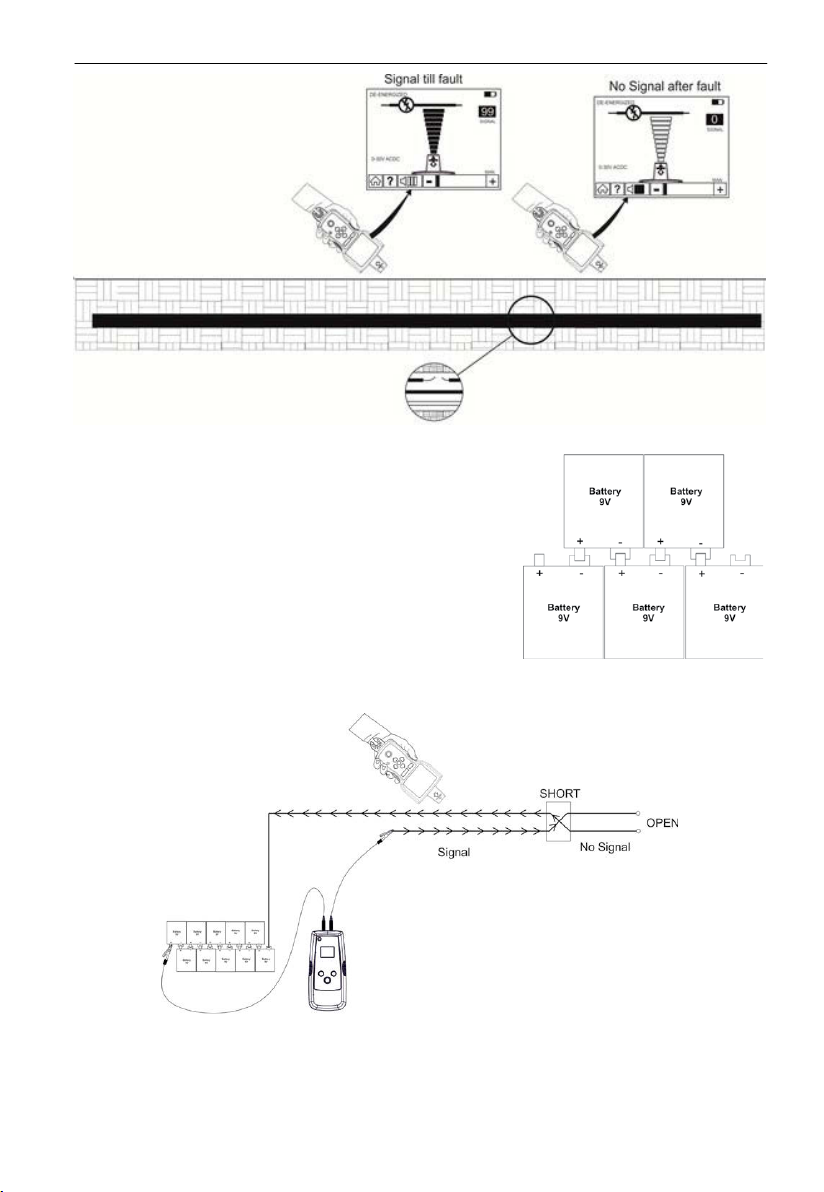
4.2 Finding Breaks/Opens
It
is possible
TIP SENSOR mod e, even
1. Make sure th at wire is de-energized.
2. Use steps described in the De-Energized TIP SENSOR mode to connect the transmitter
and perform tracing. (see section 3.2)
The tracing signal generated by the AT-7000-T transmitter will be conducted along the wire
as long as there is continuity in the metal conductor. To find the place of fault, trace the
wire until the signal stops. To verify the place of the fault, move transmitter to the other
end of the wire and repeat tracing from the opposite end. If signal stops at the exact same
location you have found the place of the break.
Not
e: If the place of fault is not found, the open may be a high resistance break (partially
open circuit). Such a break would stop higher currents from flowing but will conduct
the tracing signal through the break. Such faults will not be detected until the wire is
completely open.
to
pinpoint the exact location where the wire is broken using the de-energized
if
wire is located behind walls, floors or ceilings:
Page 26
23
AT-7000-T
4. sPeciaL aPPLications
Trace
moving
receiver
the wire by
back and forth at
4.3 Finding Shorts
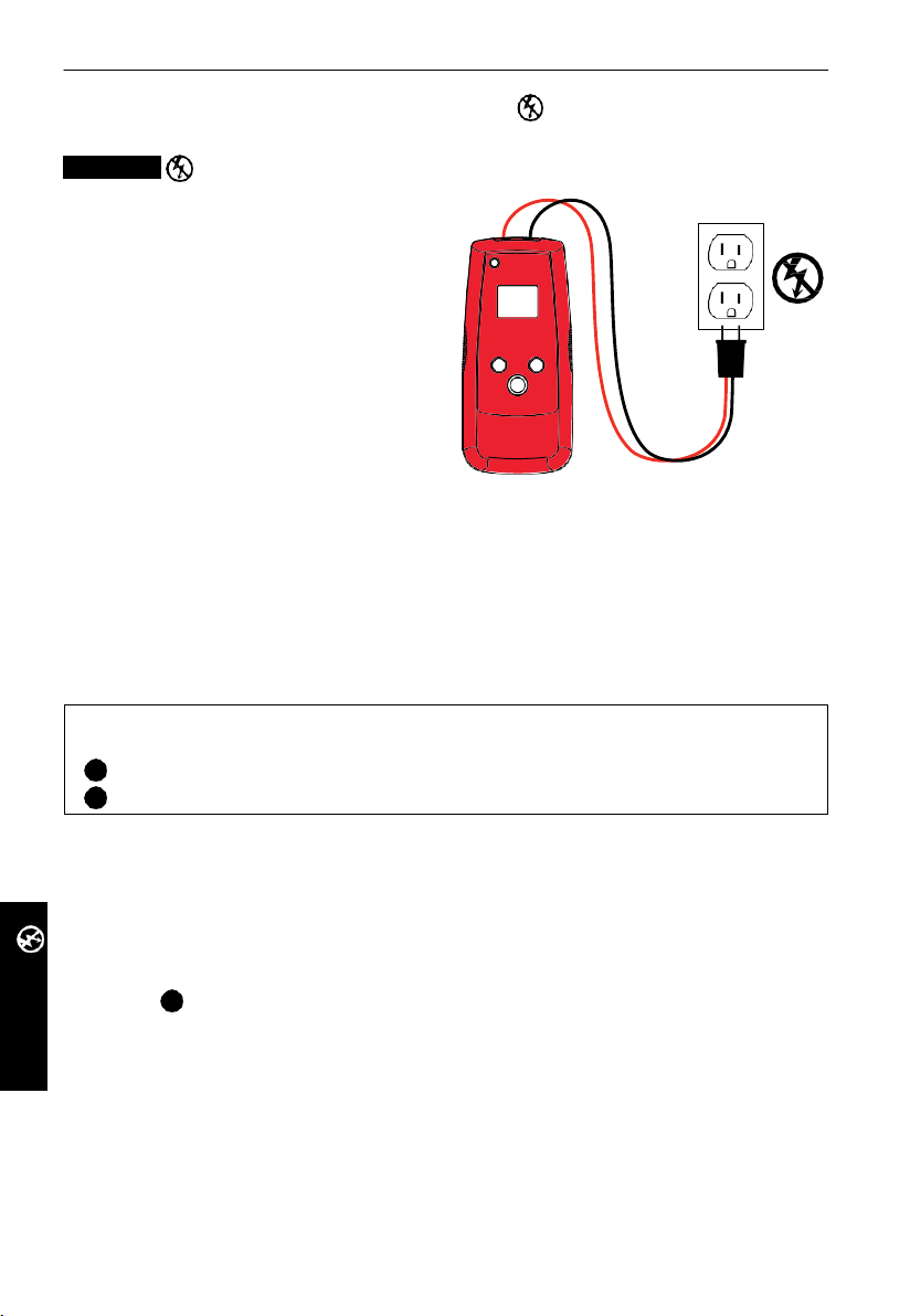
Shorted wires will cause a breaker to trip. Disconnect the
wires, and make sure the ends of the wires on both sides
of the cabl e are is olated from each other and other wires
or loads.
Interconnect ten (10) 9V batteries in series, by connecting
negative “-“contact of one battery to the positive “+” on
the other one. The 10 batteries will create safe 90V DC
power s ourc e.
Connect the circuit as shown in the illustration below.
Setup the receiver to Energized TIP SENSOR mode. Start tracing the cable until you find the
location where the signal stops. To verify the place of the fault, move the transmitter to the
other end of the wire and repeat tracing from the opposite end. If the signal stops at the
exact same location you have found the place of break.
Note: This method will be affected by signal cancellation effect. Exp ect a very weak signal.
Page 27
24
4. sPeciaL aPPLications
AT-7000-T
4.4
Tracing Wires in Metal Conduit
The AT-7000-R receiver will not be able to pick up the signal from the wire through the
metal conduit. The metal conduit will completely shield the tracing signal.
Note: The receiver will be able to det ect wires in non-metallic conduit. For these
applications follow general tracing guidelines.
In order to trace wires in conduit:
1. Use either energized or de-energized TIP SENSOR mode (refer to section 3.1 or 3.2 as
appropriate)
2. Open junction boxes and use the r eceiver TIP SENSOR to det ect which wire in the
junction box is carrying the signal.
Move from junction box to junction box to follow the path of the wire.
3.
Note
: Applying signal directly to the conduit will send signal through all the conduit
branches making tracing of one particular conduit path not possible.
4.5
Tracing Non-Metallic Pipes and Conduits
The AT-7000 c an indirectly trace plastic conduits and pipes using the following steps:
Insert fish tape or wire inside the conduit.
1.
2. Conn
ect the AT-7000-T transmitter red test lead to the fish tape and the green ground
wir e to a separat e gr ound (see secti on 3. 2 for furt her set-up instructions).
3. Set the R ecei ver to De- energized TIP SENSOR mode to trac e the conduit
(ref er to section 3.2).
The receiver will pick up the signal conducted by fish tape or wire through the conduit.
4.
4.6
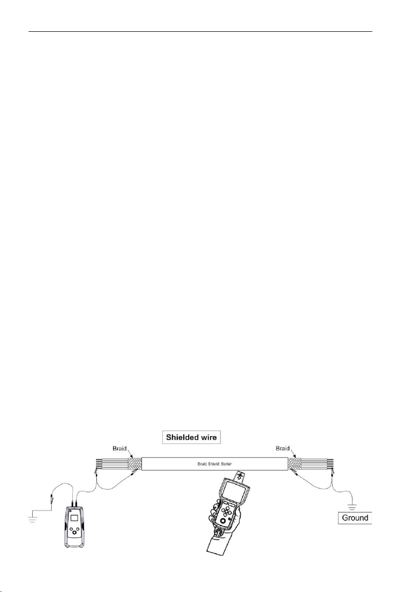
Tracing Shielded Wi res
The AT-7000-R receiver will not be able to pick up the signal from the shielded wire. The
shield will completely stop the tracing signal.
In order to trace these types of wires:
1.
Connect the AT-7000-T transmitter directly to the shield (connect red test lead to the
shield and the green test lead to the separate ground).
2.
Set the r ecei ver to the De-Energized TIP SENSOR mode to trace the wir e.
3.
For best results disconnect the shield from the ground at the point where transmitter is
connected, and leave the other end grounded.
Page 28
25
4. sPeciaL aPPLications
AT-7000-T
AT-7000-T
4.7
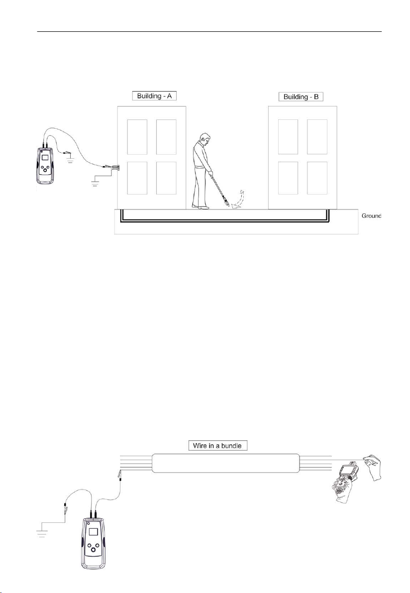
Tracing Underground Wires
Th e AT-7000 can trace wires underground, the s ame way it c an locat e wires behind walls or f loors.
Perf orm tr acing as described in Energized SMART SENSOR mode or Energized / De-Energized
TIP SENSOR modes.
You can use a hot sic k att achment to mak e tracing mor e er gonomic and convenient.
4.8
Tracing Low Voltage Wires and Data Cables
The AT-7000 can trace data, audio, and thermostat cables (to trace shielded data cables,
refer to section 4.6 “Tracing Shielded Wires”).
Tr ace data, audio, and thermostat cables as follows:
1.
Connect the AT-7000-T transmitter using the separate ground method described in
section 3.2 “Tracing De-Energized W ires”.
2.
Set the AT-7000-R recei ver to De-energized TIP SENSOR mode and trace the wire (see
section 3.2 for further detailed set-up instructions).
Connect the transmitter as shown in the diagram.
4.9
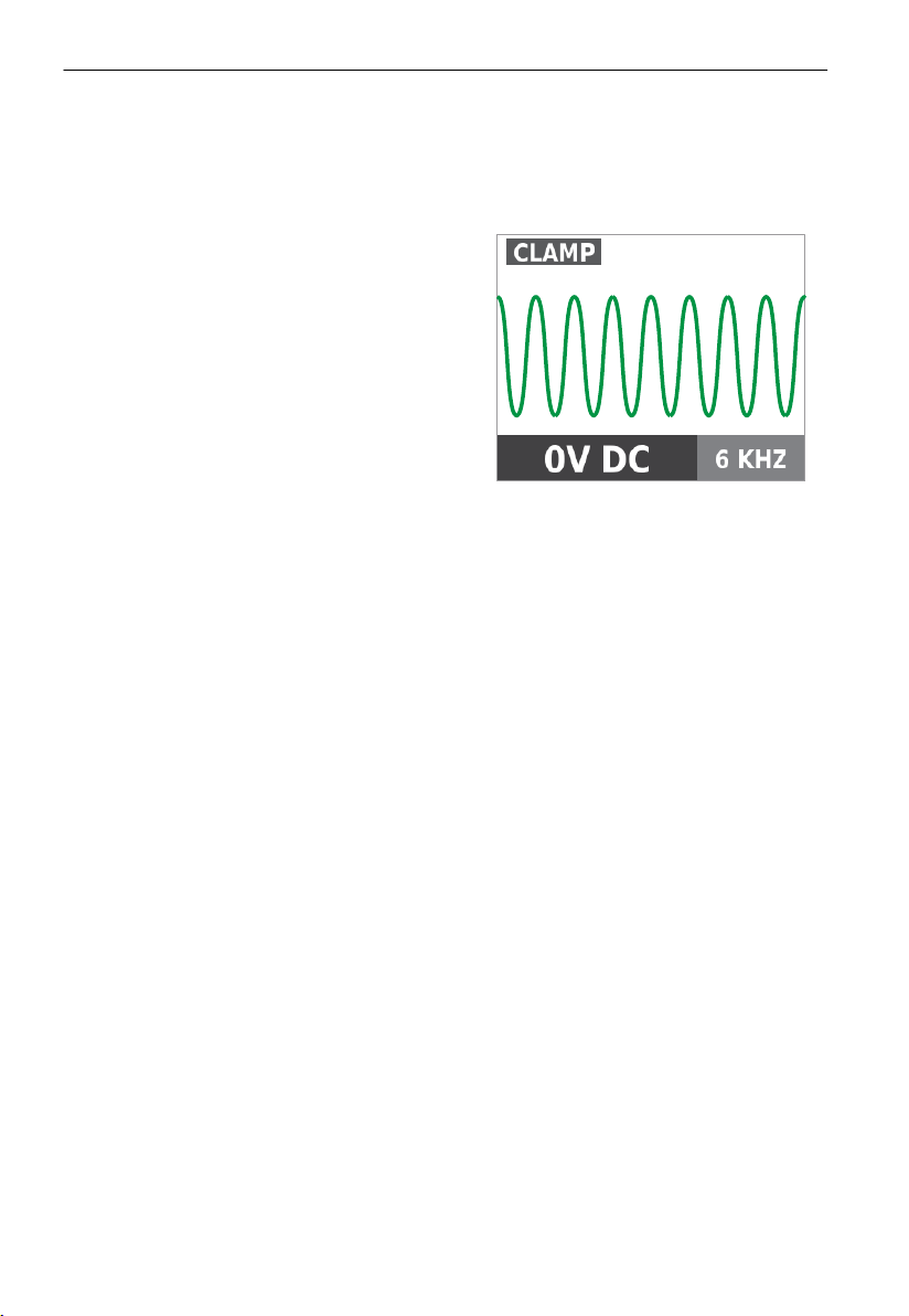
Sorting Bundled Wires
Identifying a specific wire in a bundle
Con nec t th e AT-7000-T transmitter using Energized or De-Energized T IP SENSOR mode. If
connecting to energized wire, make sure the transmitter is connected on the load sid e.
Sel ect r espectively Energized or De-energiz ed TIP sensor mode on AT-7000-R r ecei ver. As far
as it is possible pull one wire at the time way from other wires in the bundle and touch it
with
the TIP sensor. The strongest signal indicates the proper wire in the bundle.
Page 29
26
4. sPeciaL aPPLications
4.10
No Access to Bare Conductors (Signal Clamp)
The clamp ac cessor y is us ed for applications where th ere is no access to the bar e conductor
to connect transmitter test leads. When clamp is connected to the transmitter, it enables the
AT-7000-T to induce signal to energized or de-energized wire through the insulation. The
signal will travel through the wire both directions and it will affect all the branches. This
met hod is safe to us e for any s ensitive electr onic equipment.
Connect the clamp
Connect the SC-7000 test leads to the
1.
terminals of the transmitter
(polarity does not matter).
2. Clamp the SC-7000 Signal Clamp around the
conductor. To increase the signal strength
wind a few turns of conductor wire around
the clamp if poss ibl e.
Set up the AT-7000-T Transmitter:
1. Pres s ON/OFF key to turn on the transmitter. The red LED voltage status indicator should
be OFF when clamp is connected and when working with either energized or deenergized systems.
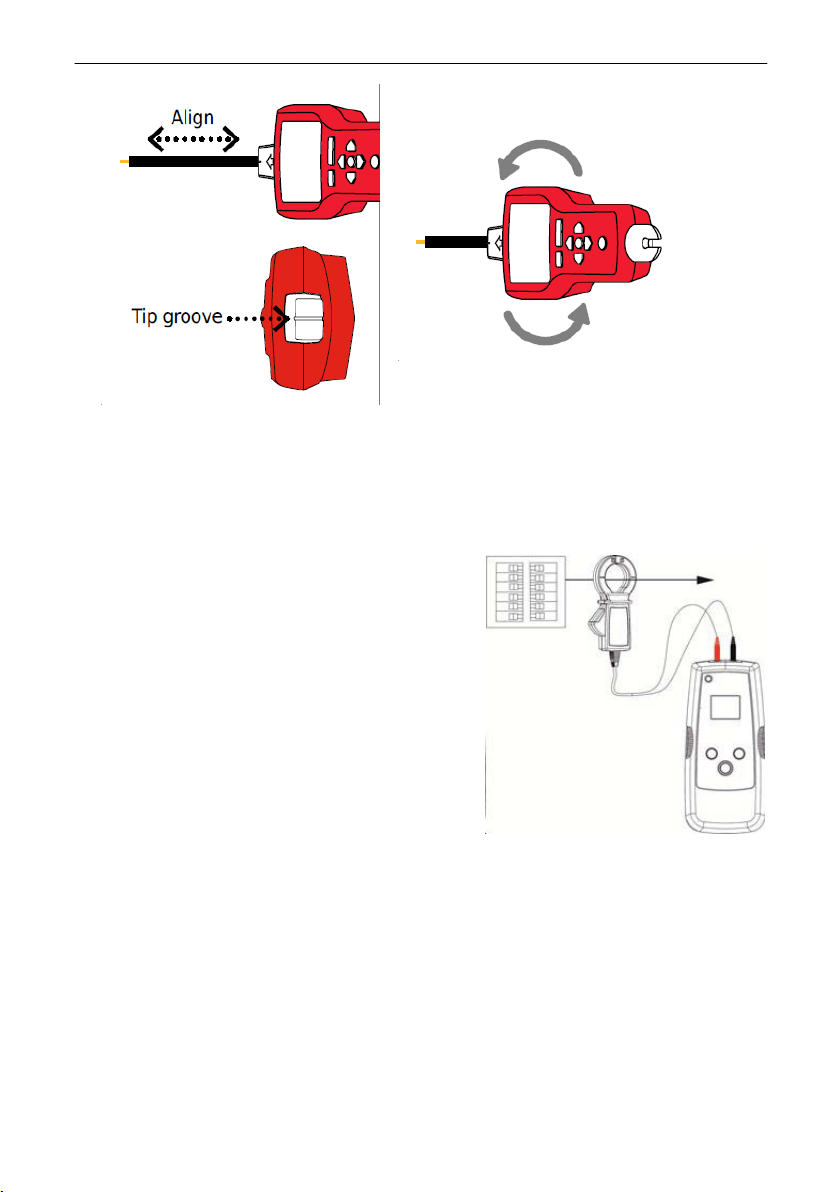
2. Press HIGH signal mode for 2 seconds to select the clamp mode on the transmitter. The
clamp mode generates a boosted 6kHz signal in order to provide superior tracing results.
The screen on the Transmitter should appear as in Figure 4.10a.
4.10a
Figure
Transmitter in CLAMP mode
Using AT-7000-R Recei ver
1. Press ‘ON/OFF’ push button to turn on the receiver and wait for the home screen (boot
up time is around 30 seconds).
2. Sel ect Energized TIP SENSOR mode by using the directional arr ows to highlight this
operating mode and pressing the yellow “ENTER” button.
3.
Hold the receiver with the Tip Sensor facing the target area.
4. Scan
adjust sensitivity to keep signal strength near 75. Increase or decrease sensitivity by
pressing +or – on the keypad.
5.
Receiver Positioning: For best results, align groove on tip sensor with wire direction as
shown. Signal may be lost if not properly aligned.
6. To verify wire direction, periodically rotate receiver 90 degrees. Signal strength will be
highest when wire is aligned with Tip Sens or groove.
target area with Tip Sensor to find highest signal level. While tracing, periodically
Page 30
27
4. sPeciaL aPPLications
Figure 4.10c
Figure 4.10b
7. PRESS ENTER when complete to return to home screen.
*Note: For best results, keep the receiver at least 3 feet from the transmitter and its test
leads to minimize signal interference and improve wire tracing results.
4.11 Locating Loads (Signal Clamp)
The clamp acc essory can be used to map loads to
specific breakers on both energized and
de-energized systems. There is no need to
disconnect power.
1. Clamp the SC-7000 around the wire at the
breaker panel.
2. Set up the tr ans mitter and recei ver as described
in the previous section 4.10 “No Access to Bare
Conductors (Inductive Clamp)’.
3. Sc an f ace plates of receptacles and wir es
connecting loads with the TIP Sensor of the
AT-7000-R. If using on a de-ener giz ed system
you mus t set the receiver to d e-energized TIP
SENSOR mode.
4. All the wires, receptacles and loads that have a
strong signal as indicated by the AT-70000-R are
con nected t o the breaker.
Page 31
28
5. maintenance
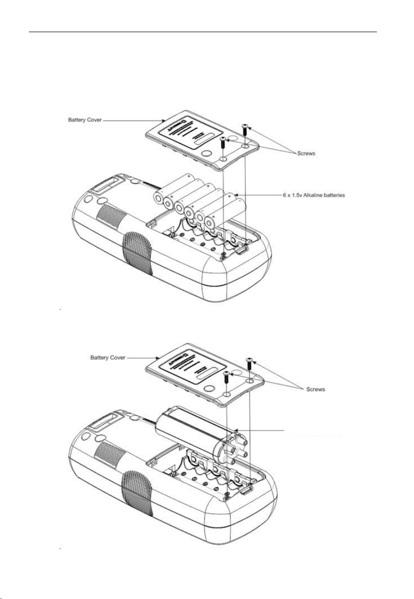
BR-7000-T
Changing battery for transmitter:
The battery compartment on the back of the AT-7000-T is designed to make it easy for
the user to change the battery. A screw is added to secure the battery in case the unit is
dropped. The 7.2V BR-7000-T Signal Booster Rechargeable Battery Pack or 6 AA alkaline
batteri es may be used. The BR-7000-T does not need to be removed to c harge. It will begin
recharging whenever the AT-7000-T is plugged into an energized outlet (90V-270V).
OR
Figure 5.1: Changing transmitter b attery
Page 32
29
5. maintenance
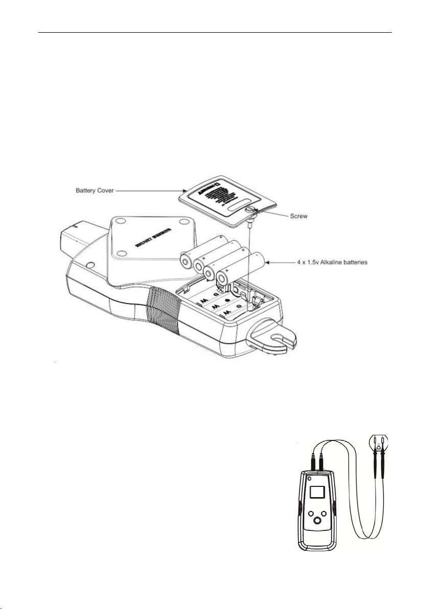
1.
Make sure that the Transmitter is turned off.
2. Use
the star screw driver to unscrew the holding screws.
3.
Remove the battery cover.
4. Install Batt eries us ing the b attery clip.
Replace the battery cover and secure it with the provided screw.
5.
Changing receiver battery:
The battery compartment on the back of the AT-7000-R is designed to make changing
batteri es easy. Four (4) AA 1.5V alkaline or 1.2V rechargeable batteries may be used.
Figure 5.2: Changing receiver battery
1.
Make sure that the Receiver is turned off.
2. Use screw driver to unscrew the captive screw.
3.
Remove the battery cover.
4.
Install batteries using the battery clip.
Replace the battery cover and secure it with the
5.
provided screw.
Transmitter battery charging:
The BR-7000 Signal B ooster Rechargeable Battery Pack will
automatically begin recharging whenever the Transmitter
is connected to an energized circuit with voltage between
90-270 Volts AC. When connected to an energized circuit the
Transmitter does not need a battery as the Transmitter uses
power from the line.
Figure 5.3
Transmitter battery charging
Page 33
30
5.
maintenance
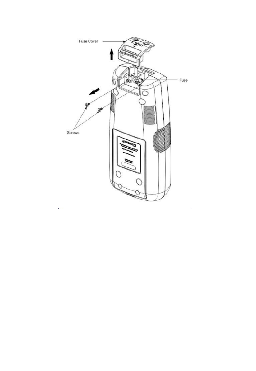
Transmitter fuse replacement:
Figure 5.4: Transmitter fus e replacement
� Warning: To avoid shock, injury, or damage to the Transmitter, disconnect test
leads before opening case.
onnect all test leads from the Transmitter.
1. Disc
2.
Make sure that the transmitter is turned off.
3. Use
the star screw driver to unscrew the holding screws.
4. Remove the fuse cover by pulling it upwards as shown in figure 5.4.
Remove the fuse from the fuse holder.
5.
6. Ins ert the new fuse in the fuse holder. 3.15A , 600V MAX, SLOW 5X20MM
7.
Insert the fuse cover and secure it with the holding screws and tighten with the Star
screw driver.
Page 34

31
6.
LCD size
LCD Dimensions
LCD type
Color LCD
Audio
0°F to 120°
F
0°F to 120°
F
-40°F to 150°
-40°F to 150°
Operating
Humidity
protection
(BR-7000-T)
(BR-7000-T)
sPecifications
LCD Resolution
(pixels)
Backlight Yes
AT-7000-R AT-7000-T SC-7000
3.5"
2.76 x 2.07
40
320 x 2
TFT
Yes
1.77"
1.1 x 1.38 in
128 x 160
RGB x T
FT
Yes
Yes
NA
NA
NA
NA
NA
NA
mDDR 64 MB
FLASH memory
Operating
Temperature
range
Storage
Temperature
Operating
altitude
Measurement
Category
Transient
Pollution degree 2
Drop test 1 meter
Power Supply
Power
consumption
Charging voltage
128 MB
95 dB
0 to 120F (-17.
49C)
(-40 to 150
65.5C)
95% R.H max
2000m
CAT IV 600V
NA 6.00kV
4x AA Alkaline battery
4xA A b attery: 2W BR-7000-T battery: 2W
No
77C to
F) (-40 to
64 MB
128 MB
No
°
(-17.77 C to 49 C)
(-40° to 65.5°
C C)
95% R.H max 95% R.H max
2000m 2000m
CAT IV 300V CAT IV 600V
(1.2/50uS surg
2 2
1 m
eter 1 meter
90-270V AC/DC,
40-400 Hz
BR-7000-T: 7.2V;
LI-ION Battery
6x AA Alkaline Battery
6xAA battery:2W
AC line voltage
(Charging state): 10W
AC line voltage: 3W
85-270V (±5%)
°
F
e)
NA
NA
NA
°
(-17.77 C to 49 C)
(-40° to 65.5°
C C)
NA
NA
NA
NA
°
F
Charging duration
Booting time 30-sec
Non-Rechargeable
Battery lifetime
No
9 Hrs
16Hrs
20-se
9 H
rs
c
NA
NA
NA
Page 35

32
6. sPecifications
(rechargeable)
IP Rating
Indication
Rechargeable
Battery lifetime
(BR-7000-T)
Leakage current
(non-rechargeable)
Leakage current
No
1.1 to 2.6uA
NA
10 H
rs
6 to 14uA
1.2 to 4u
NA
NA
A
NA
IP52
Sampling rate
Signal Response
Response time
Voltage
Measurement
NCV 90-600V AC
LED Indicator
Operating
Frequency
Acoustic
6.25kHz Signal:
62.5KS
PS
32.768kHz: 256KSPS
NCV: 62.5 kSPS
Audible beep,
bargraph display,
numeric display
Smart mode: 750 m Sec
Tip Sens or Energized:
300 mS ec
Tip Sensor De-Energized:
750 mS ec
NCV: 500 mSec
Battery monitoring:
5 Sec
NA
Accuraccy: ( 5%)
Green Flashing:
Signal D etec tion
Energized: 6.25kHz
De-Energized:
32.768kHz
1 kZ Piezo Buzzer
IP40 IP52
62.5 kSPS
Numeric di
Voltage measurement:
1.5 Sec
Battery monitoring:
5 Sec
9-300V, DC to 400Hz
A
ccuraccy:
(±10%) 9-109V AC/DC
(±5%) 110-300V AC/DC
Over-range indication:
“OL” (>330V)
High voltage cool
down for 10 mins after
60 mins of operation:
>285V
NA NA
±
Red: Energized
OFF: De_Energized
Orange: Over vol
Voltage measurement:
40-400 Hz
Energized: 6.25 kHz
De-E
32.768 kHz
NA NA
splay
nergized:
NA
NA
instantaneous
NA
NA
tage
Energized: 6.25kH
De-Energized:
32.768kHz
z
Current output
(Low ) Energized
NA
ms
NA
53 mA r
Page 36

33
6. sPecifications
7000-T Energized
De-Energized
De-Energized
1.97-in (5cm) r adius
Jaw Opening
Current output
(High) Energized
Current output
(Low ) with BR7000-T Energized
Current output
(High) with BR-
Voltage output
(Low)
Voltage output
(High)
Voltage output
(Clamp mode)
De-Energized
Range Detection
(Open air)
NA
NA
NA
NA
NA
NA
Smart mode
Pinpointing: Around
1.97-in (5 cm) r adius
( 2%)
±
Direction indication:
Up to 5FT (152.4c m)
( 2%)
±
TIP Sensor: Energized
Pinpointing: Around
1.97-in (5 cm) ( 1%)
Detection: Up to 22-FT
(670.56cm) ( 1%)
TIP Sensor: De-Energiz ed
Detection: Up to 14-FT
(426.72cm) ( 5%)
NCV (40-400 Hz)
Pinpointing: Around
±
±
±
92 mA r
ms
53 mA r
ms
120 mA r
60 Vp
120 Vp
180 Vp
NA NA
ms
-p
-p
-p 1.5 Vp-p
NA
NA
NA
NA
NA
Fuse NA
Dimensions
Weight 1.20 lb (0.544 kg)
NA
10.92x4.43x2.55-in
(
27.75x11.25x64.83cm)
NA
3.15A , 600V MAX,
SLOW 5X20MM
8.5x4x2.2-in
(21.59x10.16x5.59cm)
1.30 lb (0.593 kg
) 0.648 lb (0.294 kg)
2-in (5.08cm)
NA
8.2x3.2x 1.68-in
(208.28 x 81.28x 42.67
mm)
 Loading...