

Page 1
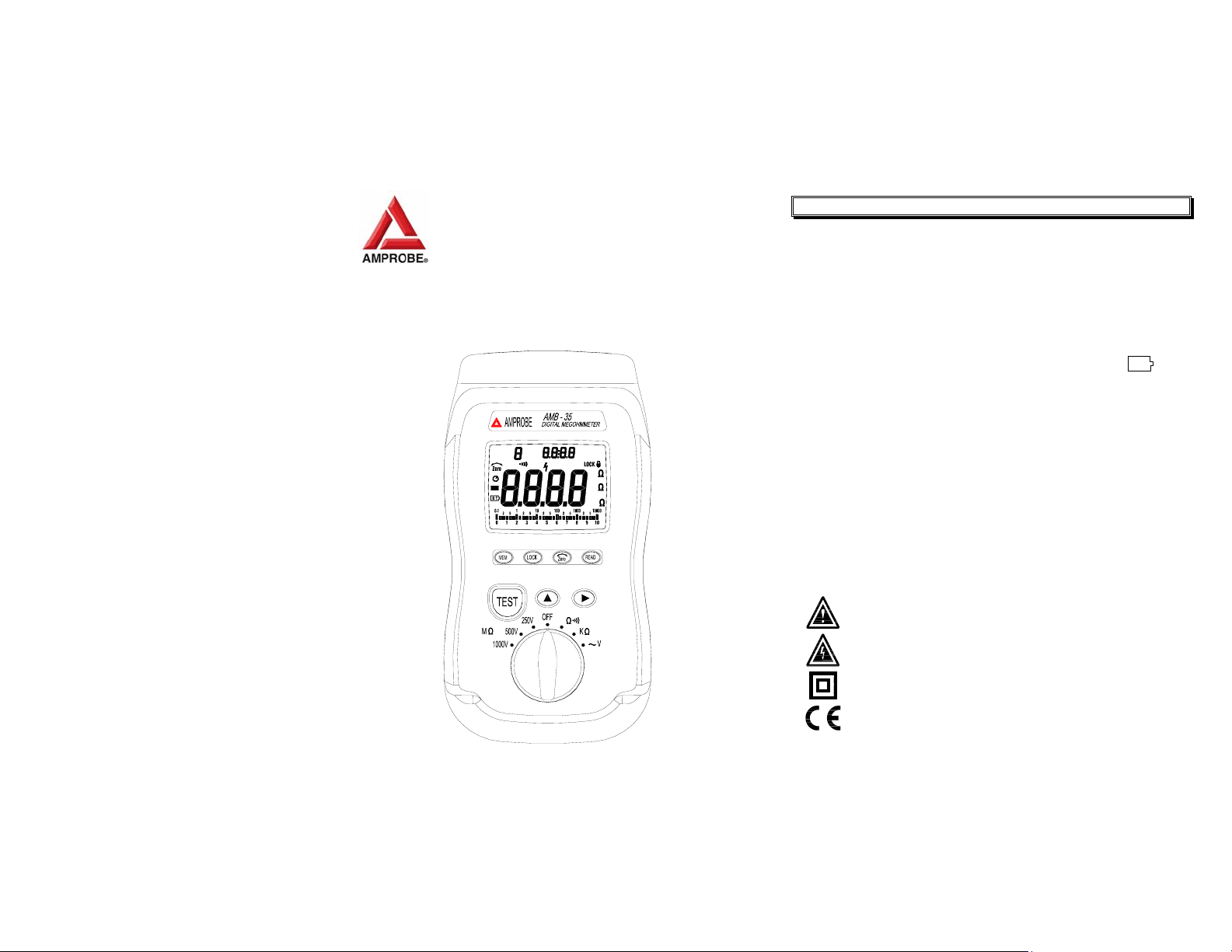
INSULATION TESTER
AMB-35
INSTRUCTION MANUAL
sACm:
M
REMEAD
HOLD
K
M
VG
1. SAFETY INFORMATION
The circuit under test must be de-energized and isolated before
connections are made except for voltage measurements.
Verify operation prior to measuring hazardous voltages (voltage
above 30V AC rms, 42V AC peak and 60V DC).
Do not touch the Circuit connections during a test.
Disconnect the hot test lead before disconnecting the neutral
test lead.
After insulation tests, to protect against electric shock, capacitive
circuits must to be discharged.
Do not use the meter if the low battery indicator (
displayed.
Test leads (including crocodile clips) must be in good order,
clean with no breaks or cracks.
Do not use the meter if it looks damaged.
Do not use the meter around explosive gases, vapors or dust.
Do not push the test button before all connections and
preparations are complete. The instrument must only be used by
suitably trained and competent persons.
Do not use the meter with any parts or cover removed.
Do not use the meter in a wet environment.
U.S. PAT. NO. 478,017
JAPAN PAT. NO. 1180870
CHINA PAT. NO. ZL02367250.1
Warnings and Safety symbols:
Caution refer to this manual before using the meter.
Dangerous voltages.
Meter is protected throughout by double insulation or
reinforced insulation.
Comply with IEC1010-1
When servicing, use only specified replacement parts.
1
BT
) is
Page 2
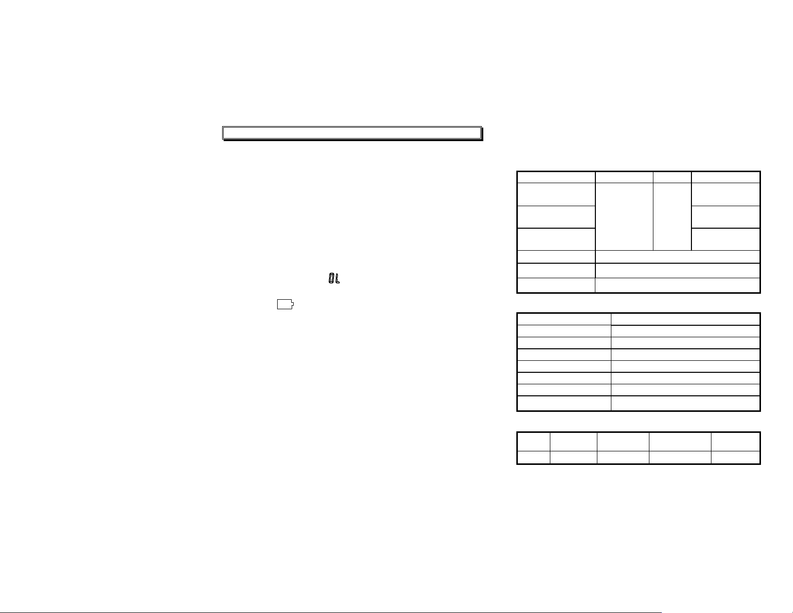
2. SPECIFICATIONS
/
/
/
Ω
2-1 General Information
Environment conditions:
c Installation CategoriesⅢ 1000V
d
Pollution Degree 2
e Altitude up to 2000 meters
f Indoor use only
Safety Meets of IEC61010-1 and IEC61557
Display : Dual display, 3-3/4 Digital readout with analog bar
Sampling Rate : 2.5 sample/sec.
Manual data Memory and Read : Memory capacity 9 set.
Over Range Indicator : “
Low Battery Indication :
Operating Temperature and Humidity:
Temperature Coefficient : 0.10 x (specified accuracy)/ ℃
Storage Temperature and Humidity :
Battery : 6 x 1.5V “AA” battery.
Fuse : 6mm x 32mm (0.25 x 1.25 inch), 0.5A 1000V, Fast Acting.
Dimensions : 235 (L) x 116 (W) x 54(H) mm ,
Weight : Approx. 520g (1.15 LB), including batteries
Accessories : Test leads, 6pcs battery, Holster, operation manual.
indication.
” will be displayed.
BT
The (
below the operating voltage.
0℃ to 50℃ (32℉ to 122℉) below 80% RH (noncondensing).
-10℃ to 60℃ (14℉ to 140℉) below 70% RH (noncondensing)
) will be displayed when the battery voltage drop
(9.3”L x 4.6”W x 2.1”H)
2
2-2 Electrical Specifications
Accuracies are specified as:
±(...% of reading + ...digits) at 23℃ ±5℃,below 80% RH.
Insulation Resistance
Range Resolution Accuracy Test Voltages
4MΩ/40MΩ/400M
1000MΩ/250V
4MΩ/40MΩ/400M
2000MΩ/500V
4MΩ/40MΩ/400M
4000MΩ/1000V
Analog Bar Graph
Nominal Current
Circuit Protection
LoΩ
Display Range
Measurement Range
Accuracy 2%+2
Resolution
Analog Bar Graph
Open Circuit Voltage 6V typical
Short Circuit Current
Circuit Protection
AC Voltage (40Hz〜500Hz)
Range Resolution Accuracy
1000V 1V 2%+1
Sensitivity : 2V
Ω
4MΩ: 1 KΩ
40MΩ: 10 K
Ω
400MΩ:100 K
4000MΩ: 10M
Ω
Test inhibited if input ≧ 30V AC or DC
200mA minimum, (0.2 to 2.0Ω)
Test inhibited if input ≧ 30V AC or DC.
3%+5
(<1000M)
Ω
Ω
5%+5
(>1000M)
0 to 4000MΩ
≧
1mA
40.00Ω
0.10Ω to 40.00Ω
0.01Ω
40.00Ω
Input
Impedance
2.5MΩ
250V+20% ~ -0%
500V+20% ~ -0%
1000V+20% ~ -0%
Overload
Protection
1000Vrms
Page 3
3
DC Voltage
Range Resolution Accuracy Input Impedance Overload Protection
1000V
-1000V
1V 1%+1
2.5MΩ
1000Vrms
Sensitivity : 2V
Resistance & Continuity
Range Resolution Accuracy
Ω
9999
1Ω
1%+2 3V 1000Vrms
Max. open Circuit
Voltage
Overload
Protection
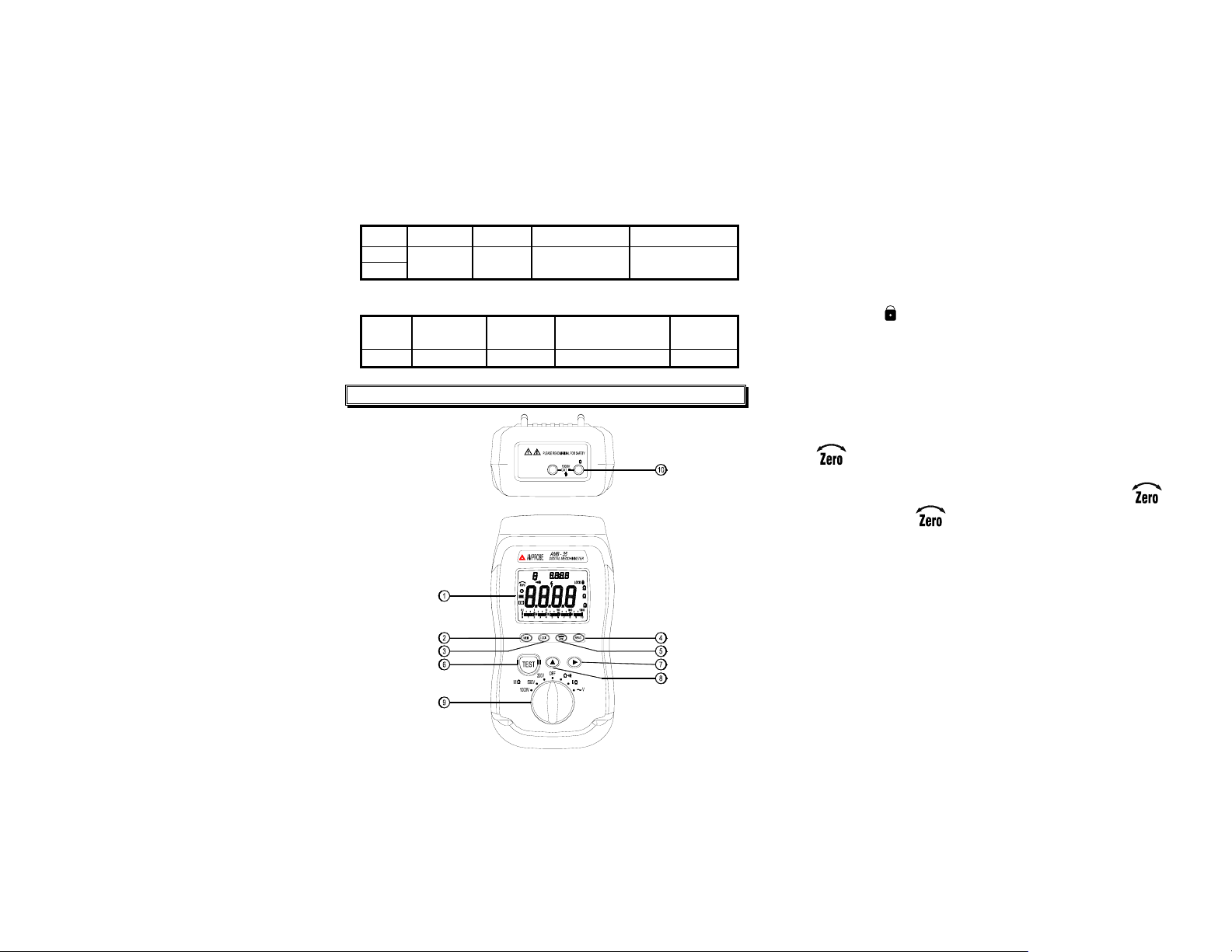
3. PARTS & CONTROLS
c
LCD display.
d
MEM key: Manual data memory control key.
e
LOCK key: Locks the Insulation test Resistance (MΩ) and Low resistan ce
(LoΩ) functions.
a). Press and hold down TEST key, then press LOCK key, the
“ LOCK ” icon appears on the display.
b). In MΩ mode continuously applies the test voltage to the circuit to
be tested. The beeper sounds every 2 seconds to remind you
that you are in the LOCK mode.
c). In LoΩ mode continuously applied the test current to the circuit to
be tested.
d). Press Lock or TEST key again to exit the mode.
f
READ key: Manual memory data reading control key.
4
COM V
g
key: In the LoΩ function, turns the test lead resistance
compensation ON.
Touch the probe tips together, then press
the
icon appears on the display and the main
key,
display indicates 0.00Ω.
h
sACm:
MEM
READ
HOLD
K
M
VG
TEST key:
a). Used for MΩ and LoΩ test functions.
b). Press and hold TEST key until the main display reading is stable.
▼▲
i j
keys : In READ mode, select the memory data location for
direct reading the data from the display.
k
Rotary switch: To select a measurement function.
l
Input terminals.
Page 4
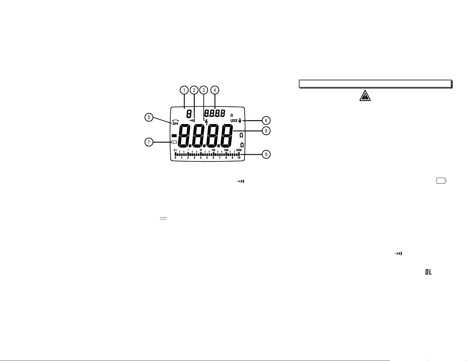
Display :
MEM
READ
5
V
DC
AC
DC
M
M
V
c
Manual data memory and read location indicator.
d
Beeper symbol shows if beeper turned on in
e
High voltage warning symbol flashes, if voltage ≧ 30V is present on the
probes.
f
Voltage applied to the probes in MΩ function, Resistance reading held
from the last measurement in MΩ and LoΩ functions and DC Voltage
reading in
g
Zero symbol is on if test leads are zeroed out.
h
Lock symbol is on if the TEST mode is locked in MΩ or LoΩ functions.
i
Low battery symbol.
j
Main display reading for all functions.
k
Analog bar graph displays resistance on a logarithmic scale and
voltage on a linear scale. The value always tracks the main display.
~
function.
V
Ω
function.
6
4. BEFORE OPERATION
Warning
To avoid electrical shock remove the test leads before opening the
case or battery cover. Do not operate with battery cover open.
To avoid electrical shock when performing resistance tests, remove
all power from the circuit to be measured.
To avoid electrical shock, first connect the test leads to the meter
inputs before you make connection to the circuit under test.
To avoid electrical shock, do not touch the test lead tips, test points
or terminals when pressing TEST.
4-1 How to connect test leads.
Connect the red test lead into the “ VΩ ” jack and the black lead
into the “ COM ” jack.
4-2 Battery Check & Replacement
1). If battery power is not sufficient, The LCD will display “
Replacement of 6 ea. new batteries, type 1.5V size “AA” is required.
2). Use a screw drive to unscrew the screw secured on battery cover.
Take out the used batteries and replace 6 pcs new batteries.
3). Place back the battery cover and secure the screw.
4-3 Auto-Power-Off
1). The meter automatically turns off after 15 minutes of non-use. In
the LoΩ mode the meter turns off after 5 minutes of non-use.
2). To turn the meter back on, turn the rotary switch to OFF, then to
the desired function.
4-4 Test Leads Check
Set the range select switch to the “
alligator clips to the test leads. Connect the alligator clips together.
The indicator should read <0.5Ω. When the leads are not
connected the display will read infinity indicated by “
will ensure that test leads are under working condition.
Ω
” range. Connect the
BT
-
-
”. This
”.
Page 5
4-5 Data Memory Storage and Read Modes:
1). Clearing the memorized data
c Set the function switch to the OFF position.
d Press and hold the "MEM" key, and rotate the function switch
to one of it’s operating modes. The "dEL" symbol will appear
on the LCD indicating the memorized data has been erased.
2). Storing Manual data
c Press the "MEM" key each time, one set of data will be stored
into the memory. At this moment, the LCD will show the
"MEM" mark and the memory address location. The total
memory size is 9 sets.
d When the memory is full, the LCD will dispaly the number "9",
the last memory address location.
3). Read Manual memory data
c Press the "READ" key to enter the memory storage mode. The
LCD will display the "READ" symbol along with the memory
address number.
d Press the " " or " " key to select the desired memory
address location.
e Press the " READ " key again to exit this mode.
7
8
5.
1). Set the function switch to V position.
2). Connect red test lead to the “VΩ” jack and the black test lead to
3). Connect the probe IN PARALLEL with the circuit to be measured.
4). Read the voltage value from the display. The meter indicates DC
VOLTAGE MEASUREMENTS
V
the “COM” terminal.
voltage on the upper right of the display and the AC voltage on the
main display.
6. Ω RESISTANCE AND CONTINUITY MEASUREMENTS
1). Set the function switch to
2). Connect the red test lead to “VΩ” terminal and the black test lead
to “COM” terminal.
3). Connect the probes to the circuit to be measured. Measure the
voltage first to ensure that no hazardous voltage is present, then
switch to ohms.
4). Read the resistance value on the display. If the resistance is
approximately 40Ω or less, the meter will beep.
Ω
position.
7. LOΩ LOW RESISTANCE MEASUREMENTS
7-1 Measuring Low Resistance
1). Set the function switch to LoΩ position.
2). Connect the red test lead to “VΩ” terminal and the black test lead
to “COM” terminal.
3). Zero out the test lead resistance (see Zero key).
4). Connect the probes to the circuit to be measured, if there is
voltage on the probes, the voltage will be displayed. A repetitive
beep will sound and the flashing high voltage symbol “
displayed to warn the user when the voltage is more than 30V.
” will be
Page 6

Please remove the voltage from the circuit under test before
proceeding with the next step.
9
5). Press and hold the TEST key until a stable reading is displayed
on the main display.
6). Release the TEST button. The upper right display holds the
resistance reading until a new test is started or a different
function is selected.
7). Exchange the red (+) and black (-) probes on the circuit and
repeat steps 5 and 6 to reverse the polarity of the test current.
The reading should be the same as the previous. This test is
useful to detect corroded connections, which can cause different
reading for both polarities.
7-2 Using the LOCK Function to Measure Resistance
The LOCK function is used to continuously supply the test
current to the circuit to be tested. This is useful for making
several measurements in succession, don’t need to push and
hold the TEST key for each measurement.
1). Press and hold the TEST button, then press the LOCK key to
enter LOCK mode.
2). Connect the probes to the desired test location in succession.
3). Press LOCK or TEST to disable the lock function.
4). The meter cannot indicate if the circuit is live in this mode.
Ensure that the circuit is deenergized before connecting the test
probes or the fuse may blow.
8. MΩ INSULATION RESISTANCE MEASUREMENTS
8-1 Measuring Insulation Resistance
Measuring insulation resistance requires the application of
potentially dangerous voltages to the circuit. This may include
exposed metal surfaces.
Before proceeding, ensure that the installation is correctly wired
and no personnel are endangered by any test.
1). Set the function switch to the desired MΩ test voltage position.
2). Connect the red test lead to “VΩ” jack and black test lead to
“COM” jack.
10
3). Connect the probes to the circuit to be measured, if there is a
voltage measured by the probes, the voltage will be displayed.
A repetitive beep and the flashing high voltage symbol “
the LCD will be present to warn the user when the voltage is
over 30V. Please remove the voltage from the circuit under test
before preceding the next step.
4). The display will show “-----“ until the TEST button is pressed.
Press and hold the TEST key. The upper right display shows
the test voltage applied to the circuit under test. The main
display shows the resistance until a stable resistance reading is
displayed on the main display.
5). After releasing the TEST key the upper right display shows the
measured resistance and the circuit discharges through the
meter. The main display indicates the decreasing voltage.
Assure the probes remain in contact with the circuit until it is
completely discharged and “-----“ again appears on the main
display. The upper right display holds the resistance reading
until a new test is performed or a different function is selected.
8-2 Using the LOCK Function to Measure Insulation Resistance
For long duration tests use the LOCK mode. This eliminates the
need to hold the TEST button for long periods.
1). Press and hold the TEST button, then press the LOCK key to
enter LOCK mode. In this mode, a potentially dangerous
voltage is continuously applied to the probes.
In this mode, if the probes are disconnected from the circuit, the
meter cannot discharge any potentially dangerous capacitive
voltages left on the circuit.
In this mode the meter cannot indicate whether or not there is a
voltage present.
Ensure that the circuit is de-energized before connecting the test
probes.
2). Press the LOCK or TEST key again to disable the Lock mode.
” on
Page 7
11
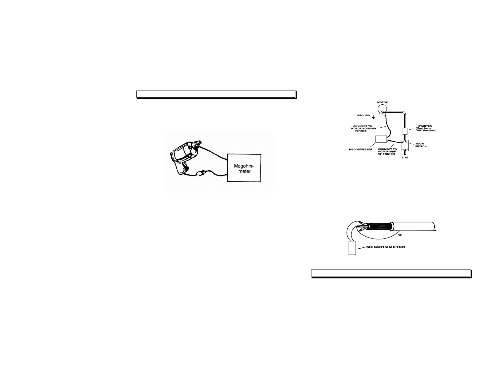
9. POWER TOOLS AND SMALL APPLIANCES
This test would also apply to other similar equipment that has a power
cord. For double insulated power tools, one lead of the megohmmeter
must be connected to the housing. The other leads would be connected
to some metal part of the tool (e.g. chuck, housing bolt).
Note: The power switch must be in the “ON” position and the main power
should be disconnected.
individually, leaving the other connected to the grounded motor housing.
The above also applies to DC Generators.
12
MOTORS
Disconnect the motor from the line by disconnecting the wires at the
motor terminals or by opening the main switch. If a main switch is used
and the motor has a starter contactor then the starter contacts must be
held closed by some means, possible by energizing the coil. In the
latter case, the measured resistance will include the resistance of the
motor, wire and all other components between the motor and the main
switch. If a problem is indicated, the motor and other components
should be checked individually.
If the motor is disconnected at the motor terminals, connect one
megohmmeter lead to the grounded motor housing and the other lead to
hot motor lead.
Disconnect the motor from the line. To test the brush rigging, field coils
and armature connect one megohmmeter lead to the grounded motor
housing and the other lead to the brush on the commutator.
If the resistance measurement indicates a problem, raise the brushes off
the commutator and separately test the armature, field coils and brush
rigging by connecting one megohmmeter lead to each of them
CABLES
Disconnect the cable from power. Also, disconnect the opposite end of the
cable to avoid any leakage due to the load. Check each conductor to
ground and/or lead source by connecting one megohmmeter lead to ground
and/or lead source and the other megohmmeter lead to each of the
conductors. Check insulation resistance between conductors by connecting
megohmmeter leads to conductors in pairs.
10. FUSE CHECK & REPLACEMENT
10-1 Testing the Fuse
1). Set the function switch to LoΩ position.
2). Connect the test leads to the input terminals and short then together.
Page 8

3). Press TEST key, the display should indicate approximately 0.5Ω, if the
display reads OL, replace the fuse as described next and test again.
13
10-2 Replace the Fuse
Warning
To avoid electric shock, personal injury or damage to the meter, use
only the specified fuse.
1). Set the function switch to OFF position.
2). Disconnect test leads from any power source.
3). Place the meter face down on a nonabrasive surface and loosen the
four screws.
4). Take off the bottom cover.
5). Remove the fuse, replace with a new fuse.
6). Place the bottom cover on and secure the four screws.
7). Test the fuse (refer 10-1 Testing the Fuse).
11. BATTERY REPLACEMENT
1). Set the function switch to OFF position.
2). Disconnect test leads from any power source.
3). Place the meter face down on a nonabrasive surface and loosen the
two screws.
4). Take off the battery cover.
5). Remove the battery, replace with six new batteries.
6). Place the battery cover on and secure the two screws.
12. MAINTENANCE & CLEANING
Maintenance & Clearing :
1). Repairs or servicing not covered in this manual should only be
performed by qualified personnel.
2). Periodically wipe the case with a dry cloth.
Do not use abrasives or solvents on this instrument.
14
WARRANTY
Congratulations! Your new instrument has been quality crafted
according to quality standards and contains quality components and
workmanship. It has been inspected for proper operation of all of its
functions and tested by qualified factory technicians according to the
long-established standards of our company.
Your instrument has a limited warranty against defective materials
and/or workmanship for one year from the date of purchase provided
that, in the opinion of the factory, the instrument has not been tampered
with or taken apart.
Should your instrument fail due to defective materials, and/or
workmanship during this one-year period, a no charge repair or
replacement will be made to the original purchaser. Please have
your dated bill of sale, which must identify the instrument model
number and serial number and call the number listed below:
Repair Department
ATP – Amprobe, TIF, Promax
Miramar, FL
Phone: 954-499-5400
800-327-5060
Fax: 954-499-5454
Website: www.Amprobe.com
Please obtain an RMA number before returning product for repair.
Outside the U.S.A. the local representative will assist you. Above
limited warranty covers repair and replacement of instrument only and
no other obligation is stated or implied.
Miramar, FL
Phone: 954-499-5400
Fax: 954-499-5454
Page 9

www.Amprobe.com
Sep-2003
 Loading...