

Page 1
AM-560
Advanced HVAC
Multimeter
AM-570
Industrial Multimeter
User Manual
EN FR ES
Page 2

Page 3

AM-560
Advanced HVAC Multimeter
AM-570
Industrial Multimeter
User Manual
10/2017, Rev.4
©2017 Amprobe Test Tools.
All rights reserved. Printed in China.
English
Page 4

Limited Warranty and Limitation of Liability
Your Amprobe product will be free from defects in material and workmanship for one year from
the date of purchase unless local laws require otherwise. This warranty does not cover fuses,
disposable batteries or damage from accident, neglect, misuse, alteration, contamination, or
abnormal conditions of operation or handling. Resellers are not authorized to extend any other
warranty on the behalf of Amprobe. To obtain service during the warranty period, return the
product with proof of purchase to an authorized Amprobe Service Center or to an Amprobe
dealer or distributor. See Repair Section for details. THIS WARRANTY IS YOUR ONLY REMEDY.
ALL OTHER WARRANTIES - WHETHER EXPRESS, IMPLIED OR STATUTORY - INCLUDING IMPLIED
WARRANTIES OF FITNESS FOR A PARTICULAR PURPOSE OR MERCHANTABILITY, ARE HEREBY
DISCLAIMED. MANUFACTURER SHALL NOT BE LIABLE FOR ANY SPECIAL, INDIRECT, INCIDENTAL
OR CONSEQUENTIAL DAMAGES OR LOSSES, ARISING FROM ANY CAUSE OR THEORY. Since
some states or countries do not allow the exclusion or limitation of an implied warranty or of
incidental or consequential damages, this limitation of liability may not apply to you.
Repair
All Amprobe returned for warranty or non-warranty repair or for calibration should be
accompanied by the following: your name, company’s name, address, telephone number, and
proof of purchase. Additionally, please include a brief description of the problem or the service
requested and include the test leads with the meter. Non-warranty repair or replacement charges
should be remitted in the form of a check, a money order, credit card with expiration date, or a
purchase order made payable to Amprobe.
In-warranty Repairs and Replacement – All Countries
Please read the warranty statement and check your battery before requesting repair. During the
warranty period, any defective test tool can be returned to your Amprobe distributor for an exchange
for the same or like product. Please check the “Where to Buy” section on amprobe.com for a list
of distributors near you. Additionally, in the United States and Canada, in-warranty repair and
replacement units can also be sent to an Amprobe Service Center (see address below).
Non-warranty Repairs and Replacement – United States and Canada
Non-warranty repairs in the United States and Canada should be sent to an Amprobe Service
Center. Call Amprobe or inquire at your point of purchase for current repair and replacement rates.
USA Canada
Amprobe Amprobe
Everett, WA 98203 Mississauga, ON L4Z 1X9
Tel: 877-AMPROBE (267-7623) Tel: 905-890-7600
Non-Warranty Repairs and Replacement – Europe
European non-warranty units can be replaced by your Beha-Amprobe distributor for a nominal charge.
Please check the “Where to Buy” section on beha-amprobe.com for a list of distributors near you.
Beha-Amprobe
Division and reg. trademark of Fluke Corp. (USA)
Germany* United Kingdom The Netherlands - Headquarters**
In den Engematten 14 52 Hurricane Way Science Park Eindhoven 5110
79286 Glottertal Norwich, Norfolk 5692 EC Son
Germany NR6 6JB United Kingdom The Netherlands
Phone: +49 (0) 7684 8009 - 0 Phone: +44 (0) 1603 25 6662 Phone: +31 (0) 40 267 51 00
beha-amprobe.de beha-amprobe.com beha-amprobe.com
*(Correspondence only – no repair or replacement available from this address. European customers please
contact your distributor.)
**single contact address in EEA Fluke Europe BV
Page 5
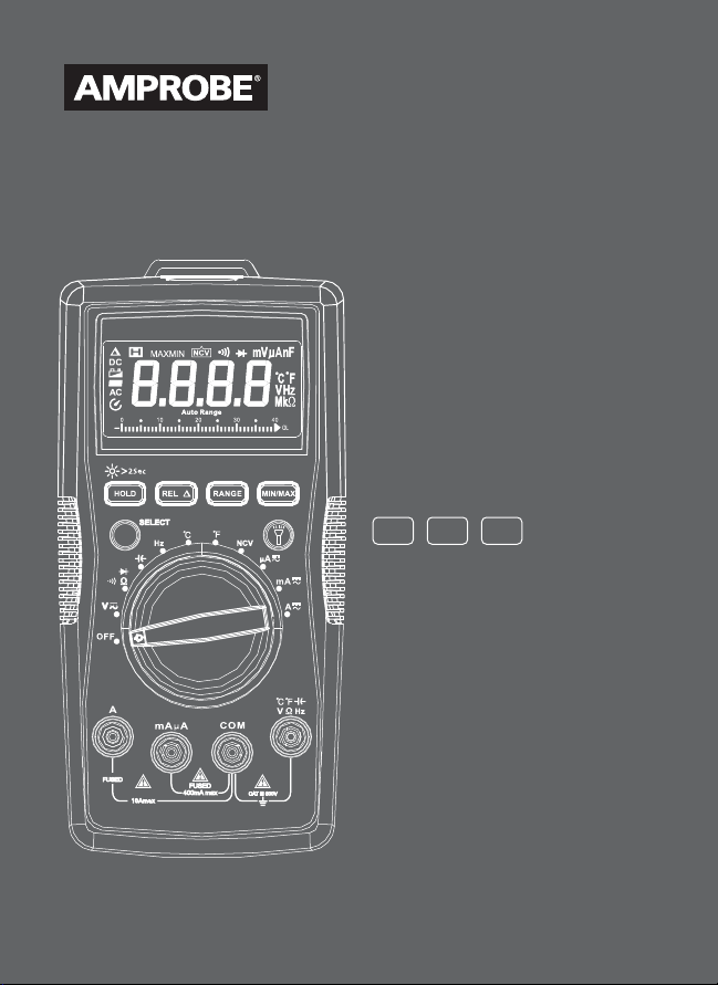
AM-560 Advanced HVAC Multimeter
AM-570 Industrial Multimeter
1
7
2
3
4 46
5
10
7
89
Flash light
1
LCD Display
2
Push buttons (See making measurement for button functions)
3
AM-570: Low-impedance button
4
AM-560: Backlight button
Rotary switch
5
SELECT button
6
Input terminal for voltage, diode, capacitance, resistance,
7
continuity and temperature measurement
COM (return) terminal for all measurements
8
Input terminal for AC/DC mA/uA measurement
9
10
Input terminal for AC/DC A measurement to10A
6
Page 6

Screen Display
26
2 4
25
24
27
3
7
18
6
28
Auto- or Manual- range
1
Direct current
2
Negative reading
3
Alternate current
4
True-rms value
5
Low battery indicator
6
Data hold
7
Diode test
8
Continuity test
9
10
Relative zero mode
11
Non-contact Voltage
detection mode
12
Measurement units
for Resistance
13
Measurement units
for Frequency
14
Measurement units for Voltage
15
Measurement units for Current
5
10 19 2011 21
16
Measurement units for Capacitance
17
Duty cycle
18
Auto power off
19
Maximum / minimum reading
memory
20
Positive / negative peak
reading memory
21
Measurement unit for temperature
22
Low-pass filter
23
400KΩ low-impedance test
(AM-570 only)
24
Temperature measurement T1 or T2
25
Temperature measurement T1 - T2
26
Warning for error input terminals
connection for test leads
27
Hazardous Voltage presence
28
Analog bar graph display
17
16
12
13
14 15
9
2223
81
Page 7

AM-560 Advanced HVAC Multimeter
AM-570 Industrial Multimeter
CONTENTS
SYMBOL .................................................................................................................2
SAFETY INFORMATION .........................................................................................2
UNPACKING AND INSPECTION .............................................................................3
FEATURES ...............................................................................................................4
MAKING MEASUREMENT .....................................................................................5
Rotary Switch Positions ....................................................................................6
Function Buttons ..............................................................................................6
Measuring AC and DC Voltage ........................................................................9
Low Pass Filter ...................................................................................................9
Measuring Frequency / Duty Cycle ...................................................................11
Measuring AC and DC Current ........................................................................13
Measuring Resistance .......................................................................................14
Measuring Continuity ......................................................................................15
Measuring Capacitance ....................................................................................16
Measuring Diode ...............................................................................................17
Measuring Temperature °C / °F ........................................................................18
Non-Contact Voltage Detection .......................................................................19
SPECIFICATIONS ....................................................................................................20
MAINTENANCE ......................................................................................................24
BATTERY AND FUSE REPLACEMENT .....................................................................25
1
Page 8

SYMBOLS
Caution! Risk of electric shock.
Caution! Refer to the explanation in this manual
Alternating Current (AC)
Direct Current (DC)
The equipment is protected by double insulation or reinforced
insulation
Earth ground
Audible tone
Battery
Complies with European directives
Conforms to relevant Australian standards
Canadian Standards Association (NRTL/C)
Do not dispose of this product as unsorted municipal waste
Contact a qualified recycler
SAFETY INFORMATION
The meters comply with:
IEC/EN 61010-1 3rd Edition Pollution Degree 2, Measurement Category IV 600V
and Measurement Category III 1000V
IEC/EN 61010-2-31 for test leads
EMC IEC/EN 61326-1
Measurement Category IV (CAT IV) is for measurements performed at the
source of the low-voltage installation. Examples are electricity meters and
measurements on primary overcurrent protection devices and ripple control
units.
Measurement Category III (CAT III) is for measurements performed in the
building installation. Examples are measurements on distribution boards,
2
Page 9

circuit- breakers, wiring, including cables, bus-bars, junction boxes, switches,
socket-outlets in the fixed installation, and equipment for industrial use
and some other equipment, for example, stationary motors with permanent
connection to the fixed installation.
WARNING: Read before using
• To avoid possible electrical shock or personal injury, follow these
instructions and use the Meter only as specied in this manual.
• Do not use the Meter or test leads if they appear damaged, or if
the Meter is not operating properly. If in doubt, have the Meter
serviced.
• Always use the proper function and range for measurements.
• Before rotating the function range selection switch, disconnect
test probe from circuit under test.
• Verify the Meter’s operation by measuring on a known voltage
source.
• Do not apply more than the rated voltage, as marked on the Meter,
between the test probe or between any test probe and earth ground.
• Use the Meter with caution for voltages above 30 V ac rms, 42 V
ac peak, or 60 Vdc. These voltages pose electrical shock hazards.
• Disconnect circuit power and discharge all high-voltage capacitors
before testing resistance.
• Do not use the Meter around explosive gas or vapor.
• When using the test leads, keep your ngers behind the nger guards.
UNPACKING AND INSPECTION
Your shipping carton should include:
1 AM-560 or AM-570 Multimeter
1 Pair of test leads
2 Temperature probes
1 Temperature adaptor
1 Velcro strap
1 9V (6F22) battery (installed)
1 Users manual
1 Carrying case
If any of the items are damaged or missing, return the complete package to
the place of purchase for an exchange.
3
Page 10

FEATURES
The multimeter designed for professional HVAC technicians. The AM-560
measures a complete range of electrical parameters and features. Key
functions include: temperature, capacitance to check the motor startup
capacitors, micro amps for flame sensor troubleshooting, and a low pass filter
to take accurate measurements on variable frequency drives. With a builtin flashlight, and non-contact voltage detection, the AM-560 is the choice
multimeter for the professional HVAC technician. This meter is safety rated to
CAT IV 600V and CAT III 1000V for the most advanced HVAC troubleshooting
needs.
The Amprobe AM-570 is a fully featured multimeter designed for professional
electricians who need to maintain service or troubleshoot advanced electrical
systems. True-rms sensing accurately measures voltage on systems affected by
harmonics; built-in flashlight allows you to identify wires while working in
dark conditions, and non-contact voltage detection allows for quick go-no-go
checks without the need for an additional tool. The AM-570 also features dual
input temperature measurement, a low-impedance function to detect stray
voltage, and a low pass filter to accurately take measurements on variable
frequency drives. Safety rated to CAT IV 600V and CAT III 1000V for use in the
most industrial applications.
• Measurements: AC/DC Voltage up to 1000V, ac/dc current, Resistance,
Frequency, Capacitance, Temperature, duty cycle.
• Special Functions:
- Low Z - to detect “ghost” voltages (for AM-570 only)
- Low pass filter for variable frequency drives
- Non-contact Voltage detection
- Audible continuity
- Diode test
• Dual reading backlit LCD display with analog bargraph
• Events:
- Data hold
- MAX / MIN memory
- Peak hold (crest)
- Relative zero mode
• Built-in flash light
• Built-in test leads storage and “third hand holder”
• Warning against improper test leads connection
4
Page 11
• Auto and manual ranging
• Auto power off
• Low battery warning
• Velcro strap to hang a meter
• Safety: CAT IV 600V, CAT III 1000V
MAKING MEASUREMENT
1. Use the proper function and range for measurements.
2. To avoid possible electrical shock, personal injury or damages to the
Meter, disconnect circuit power and discharge all high-voltage capacitors
before testing resistance and diode.
3. Connecting test leads:
• Connect the common (COM) test lead to the circuit before connecting
the live lead;
• After measurement, remove live lead before removing the common
(COM) test lead from the circuit
4. Symbol “OL” is displayed on LCD when the measurement is out of range.
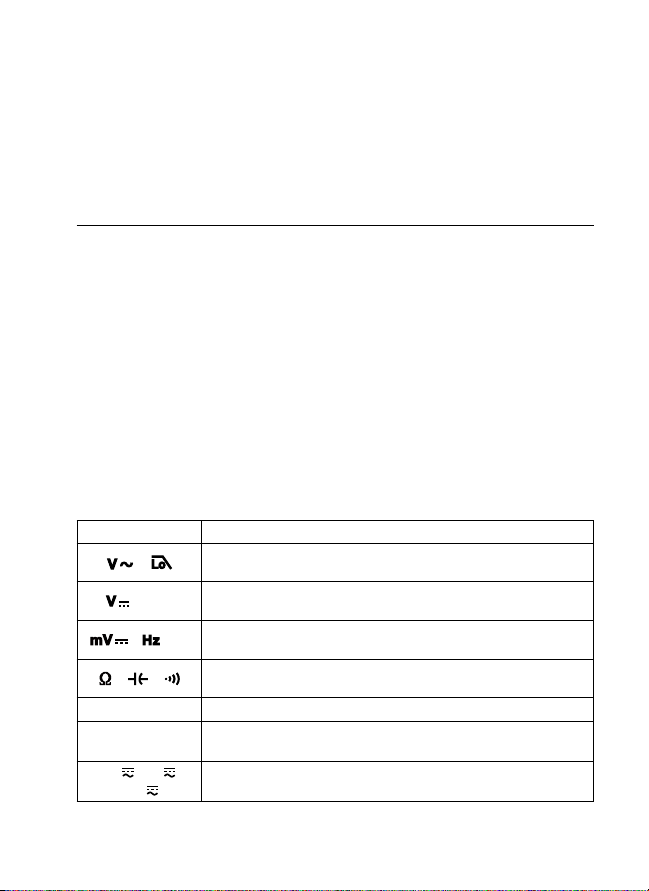
Rotary Switch Positions
Switch Position Measurement Function
/
/ NCV
/ / %
/ /
°C °F
mA
μA
10A
AC voltage measurement / Low-pass filter (1kHz).
Use SELECT button to select alternate function.
DC voltage measurement / Non-contact Voltage
detection.Use SELECT button to select alternate function.
DC millivolt measurement / Frequency / Duty cycle
Use SELECT button to select alternate function.
Resistance / Capacitance / Continuity measurement.
Use SELECT button to select alternate function.
Voltage measurement of diode PN junction (diode test).
Temperature measurement.
Use SELECT button to select temperature unit °C or °F.
AC or DC current measurement.
Use SELECT button to select alternate function ac or dc
5
Page 12
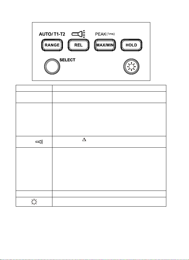
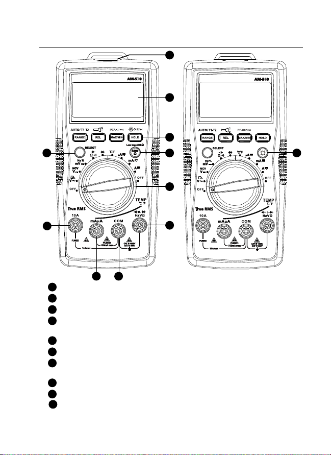
AM-560 Function Buttons
Button Measurement Function
SELECT
RANGE /
AUTO T1-T2
REL /
MAX/MIN /
PEAK(1ms)
HOLD Display freezes present reading.
Press the yellow SELECT button to select alternate
measurement functions on the rotary switch.
Manual or Auto range switching for voltage current,
resistance and capacitance. The default setting is autoranging, press to switch to manual ranging. Press for 2
seconds to return to auto-ranging.
T1 or T2 or T1-T2 function switching for temperature
measurement.
Relative mode / Press >2 seconds to turn ON or turn
OFF flash light.
Press to enter maximum / minimum reading memory
mode. Press again for maximum reading; press again for
minimum reading. Press > 2 seconds to exit maximum/
minimum reading mode.
Press > 2 seconds to enter Peak MAX/ Peak MIN mode.
Press again for Peak MAX reading; press again for Peak
MIN reading. Press > 2 sec to exit Peak MAX/ Peak MIN
reading mode.
Press > 2 seconds to turn ON or turn OFF LCD backlight.
6
Page 13

AM-570 Function Buttons
Button Measurement Function
SELECT
RANGE /
AUTO T1-T2
REL /
MAX/MIN /
PEAK(1ms)
HOLD /
Low imp. 400kΩ
Press the yellow SELECT button to select alternate
measurement functions on the rotary switch.
Manual or auto range switching for voltage current,
resistance and capacitance. The default setting is Auto
ranging, press to switch to manual ranging. Press for 2
seconds to return to auto-ranging.
T1 or T2 or T1-T2 function switching for temperature
measurement.
Relative mode / Press >2 seconds to turn ON or turn
OFF flash light.
Press to enter Maximum / minimum reading memory
mode. Press again for naximum reading; press again for
minimum reading. Press > 2 seconds to exit maximum/
minimum reading mode.
Press > 2 seconds to enter Peak MAX/ Peak MIN mode.
Press again for Peak MAX reading; press again for Peak
MIN reading. Press > 2 seconds to exit Peak MAX/ Peak
MIN reading mode.
Display freezes present reading / press > 2 seconds to turn
ON or turn OFF LCD backlight.
For voltage measurement functions only. Press and hold
the button to change the input impedance of V and COM
terminal to 400kΩ. Release 400kΩ button to return to
normal input impedance of V and COM terminal (around
10MΩ).
7
Page 14
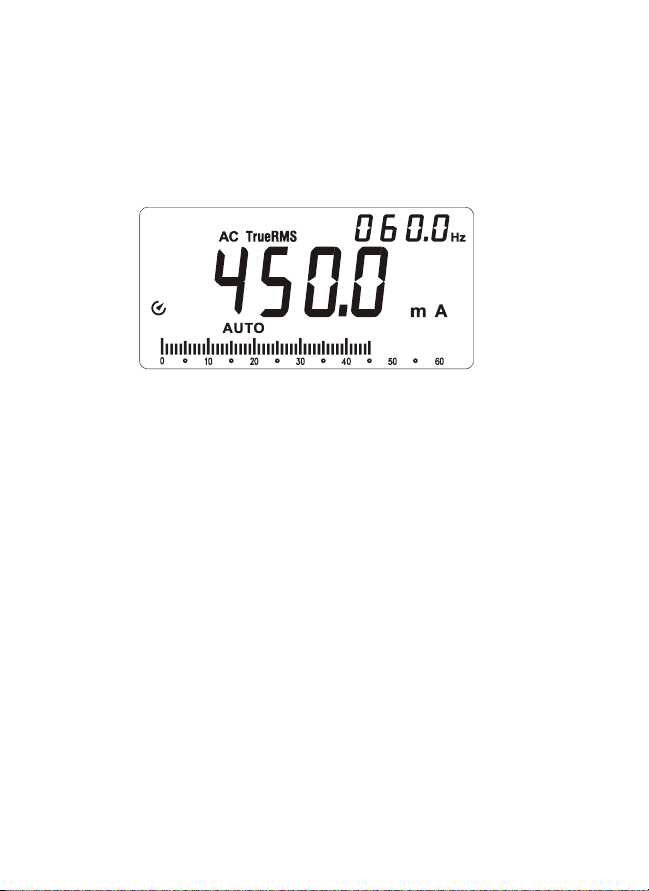
Dual Display
AC Voltage measurement
Primary display shows ac voltage.
Secondary display shows frequency.
AC Current measurement
Primary display shows ac current.
Secondary display shows frequency.
Auto Power OFF
Auto power off: Approximately 15 minutes.
When the Meter is in auto power off mode, press any button to resume
normal operation.
REL Measurement (V, A, Ω and Measurement)
The Meter will calculate the values based on the stored value when set to related
mode Display value under REL
Note: Entering relative mode is not allowed when the Meter displays “OL”.
Mode = Measured Value - Reference Value
Incorrect Input Terminal Connection Warning
To alert you about the incorrect connection of input terminals, the Meter will
display “Warning” and buzzer will sound when test leads are falsely inserted
to terminals which are not for measurement of the selected functions.
Function selected WARNING – Incorrect Terminal Connection
V, Ω, , , Hz, %,
mA μA
°C °F
10A
10A, mA μA
10A
mA μA
Hazardous Voltage Warning
LCD screen displays
when the Meter detects a voltage ≥30 Vac
or ≥42 V dc.
8
Page 15
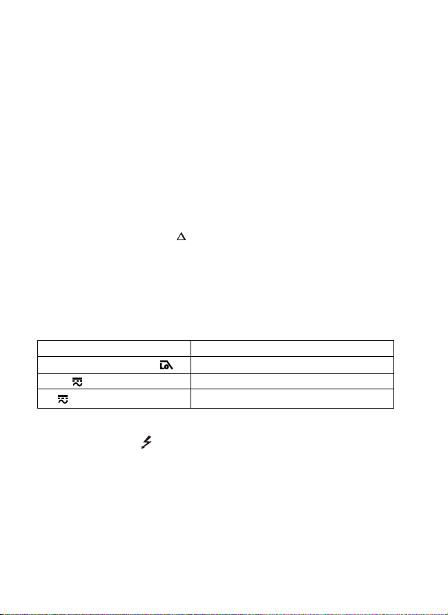
Measuring AC and DC Voltage
To avoid personal injury or damage to the Meter, do not apply
voltage higher than 1000V ac and 1000V dc.Buzzer will sound when detect a
voltage higher than 1000V ac and 1000V dc.
Low imp. 400Ω
(For only)
Low Pass Filter
• To avoid personal injury or damage to the Meter, do not use low pass
filter function to verify the presence of hazardous voltage in the circuit.
Always use Voltage function to verify hazardous voltages.
• Do not apply voltage higher than 1000V.
Measuring AC voltage with Low Pass Filter:
Turn rotary switch to position and press SELECT button for Low Pass Filter
mode,
Making measurement under ac voltage mode by a low pass filter can block
voltage above 1KHz. Low pass filter can be used to measure composite sine
wave signal generated by inverter and variable frequency motor drives.
symbol is displayed on screen.
9
Page 16
Note: The Meter goes into manual mode when Low Pass Filter mode is
enabled. Auto-range mode is not available for Low Pass Filter option.
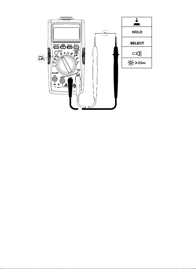
Measuring Frequency / Duty Cycle
To avoid personal injury or damage to the Meter, do not apply
voltage higher than 1000V.
1. Frequency / Duty Cycle function
Step 1: Turn the rotary switch to Hz % position. Use SELECT button for Hz
or duty cycle measurement.
Step 2: Connect test leads to the circuit. Connecting diagram see below.
10
Page 17
(for Frequency only)
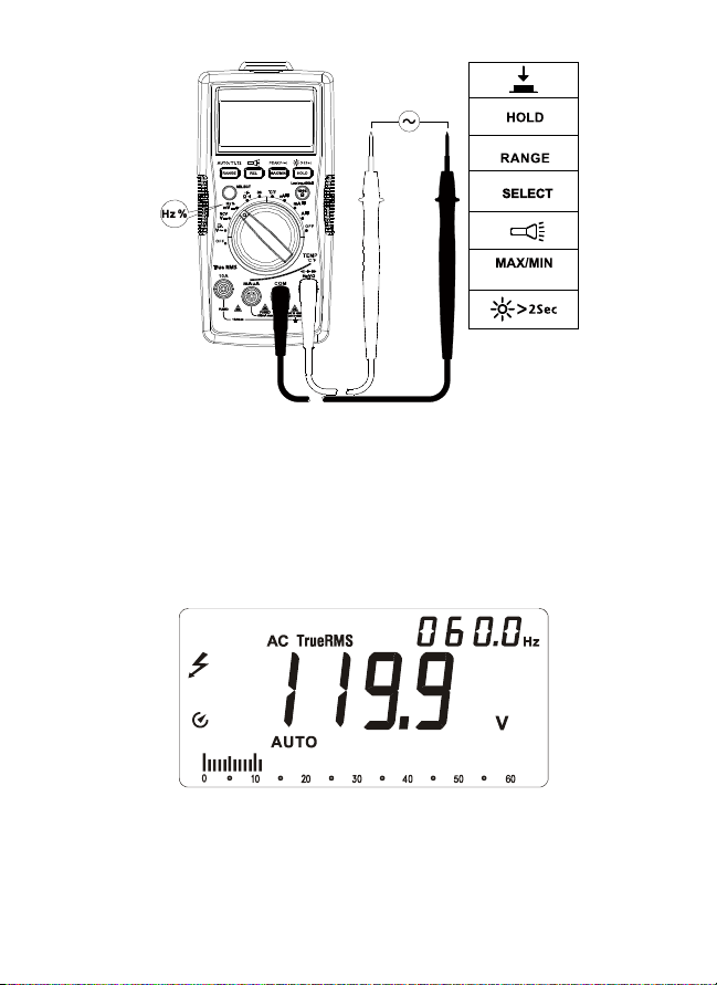
2. Measuring Frequency by using ac Voltage function
Step 1: Turn the rotary switch to position.
Step 2: Connect test leads to the circuit. Connect the common (COM) test
lead to the circuit before connecting the live lead (connecting diagram
refer to “Measuring AC Voltage”).
Primary display shows ac Voltage measurement reading.
Secondary display shows Frequency measurement reading.
11
Page 18
3. Measuring Frequency by using ac current function
Step 1: Turn the rotary switch to μA or mA or 10A position.
Step 2: Connect the test leads to the correct input 10A/mA μA current
terminal and to the circuit before powering the circuit under test
(connecting diagram refer to “Measuring AC Current”).
Primary display shows ac current measurement reading.
Secondary display shows Frequency measurement reading.
Measuring AC and DC Current
Press SELECT button to select ac or dc current measurement function.
To avoid personal injury or damage to the Meter:
1. Do not attempt to make an in-circuit current measurement when the
open-circuit potential to earth ground exceeding 1000V
2. Switch to proper function and range for your measurement.
3. Do not place the test probe in parallel with a circuit when the test leads
are connected to the current terminals.
4. Connect the test leads to the correct input 10A/mA μA current terminal
and to the circuit before powering the circuit under test.
5. For current range from 8-10A, do not measure current for more than 20
minutes. Wait for 10 minutes before taking another measurement
6. After measurement, switch OFF the circuit’s power before removing test
leads from the circuit.
12
Page 19
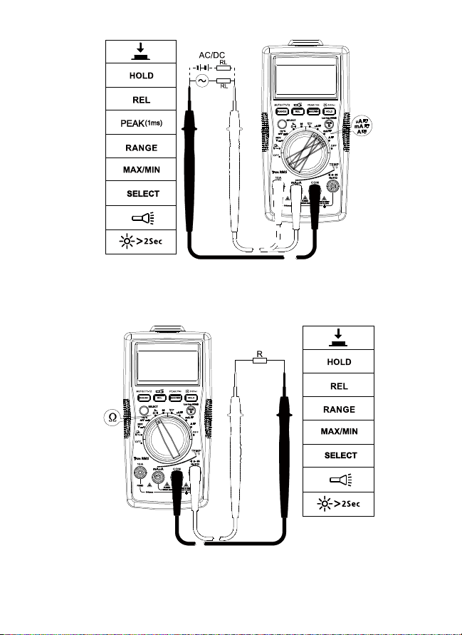
Measuring Resistance
Disconnect circuit power and discharge all high-voltage capacitors
before testing resistance.
Note: On a higher resistance measurement (>1M), the measurement may
take a few seconds to get stable reading.
Over range or open circuit indication: OL
13
Page 20
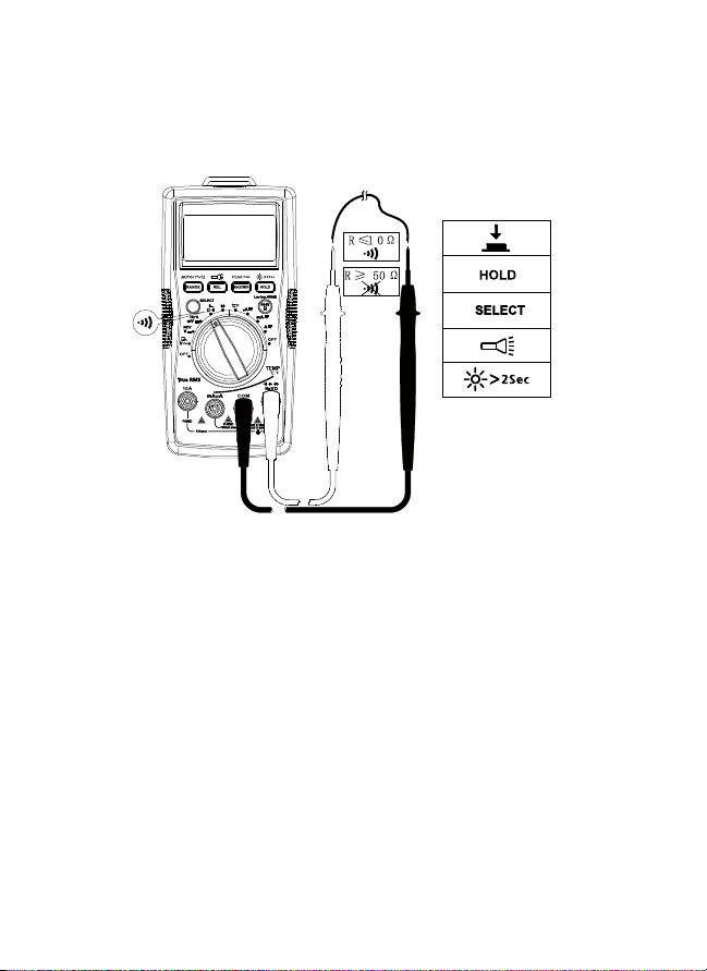
Measuring Continuity
Disconnect circuit power and discharge all high-voltage capacitors
before testing continuity.
Press SELECT button for continuity function.
Measuring Capacitance
Disconnect circuit power and discharge all high-voltage capacitors
before measuring capacitance. Use dc Voltage function to check the
capacitors are discharged.
Press SELECT button for capacitance measurement function.
14
Page 21
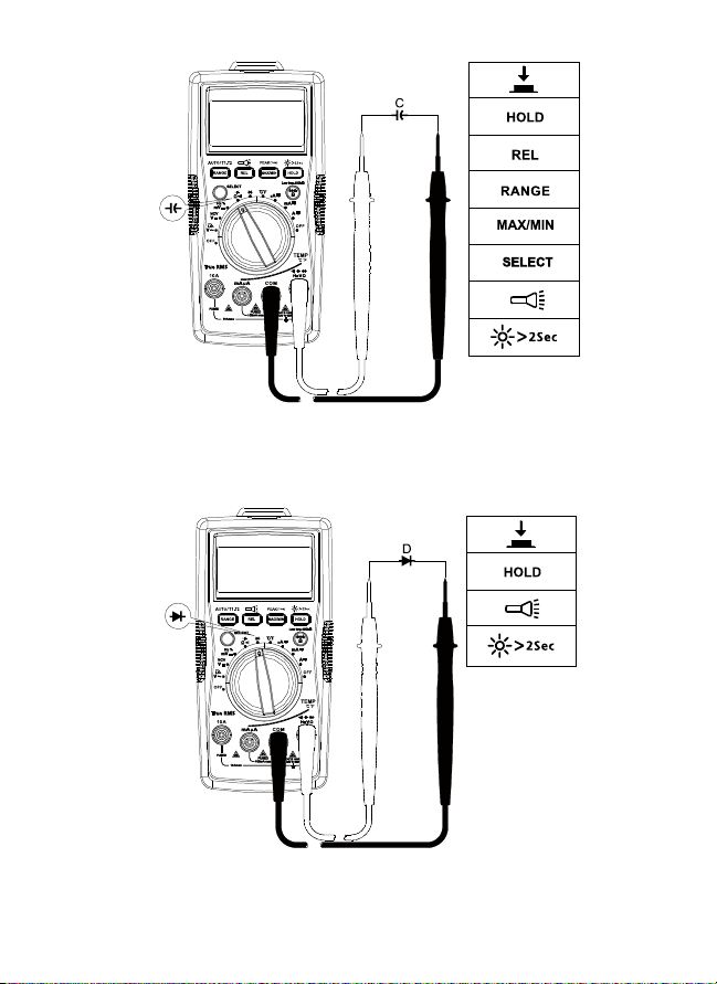
Measuring Diode
Disconnect circuit power and discharge all high-voltage capacitors
before testing diode.
Note: A typical junction Voltage drops 0.5 V to 0.8 V.
15
Page 22

Measuring Temperature °C / °F
1. To avoid personal injury or damage to the Meter, do not apply the
temperature probe to any live conductive parts.
2. Temperature sensor K-type (nickel-chromium/nichrosi) thermocouple is
suitable for temperature measurement below 230°C (446°F).
Measurement steps:
Step 1: Turn the rotary switch to °C/°F position. The display will show
“OPEN”. Press SELECT button for conversion to °F measurement.
Step 2: Connect the temperature probe (K-type) to the Meter and to the
surface to be measured. Two temperature surface points can be measured
at the same time by using the provided temperature probes.
Step 3: Press RANGE button to select temperature measurement T2 or T1-T2
(the default temperature measurement is T1).
T2
T1
16
Page 23
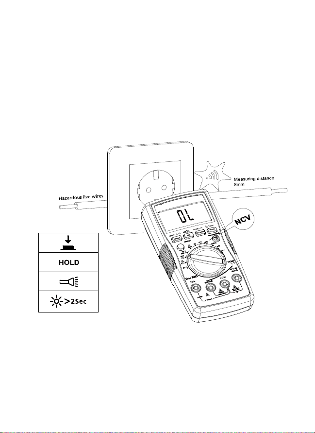
Non-Contact Voltage Detection (NCV Mode)
1. To avoid personal injury or damage to the Meter, do not test on uninsulated high voltage wires.
2. Buzzer will sound and screen will display “OL” when detecting ac
Voltage above 90V ac.
3. Do not test on hazardous live wires higher than 750V ac.
4. Before and after hazardous voltage measurements, test the Meter by
approaching to a known source such as a line ac Voltage or outlet to
determine proper operation.
5. At NCV mode, no test lead connections are required for NCV measurement.
Buzzer will sound when the detected voltage is ≥90V, and the buzzer will be
on. The distances between the wire and the meter should be ≤8mm.
17
Page 24
DETAILED SPECIFICATIONS
Ambient temperature: 23°C ±5°C (73.4°F ±9°F); Relative temperature: ≤75%
Accuracy: ±(% of reading + digits)
Maximum voltage between input terminal and earth ground:
1000V ac True-rms or 1000V dc.
Fuse for mA µA input: F1 0.5A H 1000V fast-fuse, (Φ6.3×32)mm
Fuse for 10A input: F2 11A H 1000V fast-fuse, (Φ10×38)mm
Maximum display: Digital 5999 counts, updates 3/seconds.
Analog pointer display: 61 segments. Updates 20 times/seconds.
Over-range indication: OL
Range: Automatic and Manual
Altitude: Operating ≤ 2000m
Operating temperature: 0°C~+40°C (32°F~104°F)
Relative humidity: 0°C~+30°C (32°F~86°F) ≤75%; +30°C~+40°C (86°F~104°F) ≤50%
Storage temperature: -10°C~+50°C (14°F~122°F)
Electromagnetic compatibility: In an RF filed of 1V/m = Specified accuracy ± 5%
Battery: 9V, 6F22, NEDA1604 or equivalent
Low battery indication:
Dimensions (L x W x H): 182 mm x 90 mm x 45 mm (7.2 in x 3.5 in x 1.8 in)
Weight: Approximately 354g (0.78 lb) with batteries installed
1. DC Voltage Measurement
Range Resolution Best Accuracy
600.0mV 0.1mV ±(0.5%+3 LSD)
6.000V 1mV
±(0.5%+2 LSD)60.00V 10mV
600.0V 100mV
1000V 1V ±(1.0%+2 LSD)
Input impedance: Around 10MΩ ;
Overload protection: ±1000V
18
Page 25

2. AC Voltage Measurement
Accuracy
Range Resolution
6.000V 1mV
600.0V 100mV
1000V 1V ±(1.2%+3LSD) ±(2.5%+3 LSD)
Overload protection: 1000V rms
Input impedance: Around 10MΩ
Frequency response: 45Hz– 400Hz (AM-560), 45Hz – 1kHz (AM-570)
AM-560: Average detecting, True-rms indication. rms indication.
AM-570: True-rms.
Note: Frequency (on secondary display) may not be displayed if the measured
voltage is below 20% of the display voltage range.
45Hz – 400Hz
(AM-560 / AM-570)
±(1.0%+3LSD) ±(2%+3 LSD) 60.00V 10mV
400Hz – 1kHz
(AM-570)
3. Low Pass Filter
Range Resolution Accuracy
6.000V 0.001V
60.00V 0.01V
600.0V 0.1V
1000V 1V
Block ac voltage signals above 1KHz
Overload protection: 1000Vp
45 to 200Hz ± (2%+40 LSD)
200 to 440Hz ± (6%+40 LSD)
4. Frequency Measurement
Range Resolution Accuracy
60.00Hz 0.01 Hz
600.0Hz 0.1 Hz
6.000kHz 1 Hz
60.00kHz 10 Hz
600.0 kHz 100Hz
6.000MHz 1KHz
60.00MHz 10KHz
Overload protection: 1000Vp
±(0.1%+3 LSD)
±(0.1%+3 LSD)
19
Page 26
5. Duty Cycle
Range Resolution Accuracy
10%~90% 0.01% ±(1.2%+30 LSD)
Overload protection: 1000Vp
6. DC Current Measurement
Range Resolution Accuracy
600.0μA 0.1μA
μA
mA
10 A 10.00A 10mA ±(1.5%+3 LSD)
Overload protection:
mA /µA range:F1 fuse, 0.5A H 1000V fast-fuse, (
10 A range:F2 fuse, 11A H 1000V fast-fuse, ( 10×38)mm
6000μA 1μA
60.00mA 10μA
500.0mA 0.1mA
±(1.0%+2LSD)
±(1.2%+3 LSD)
6.3×32)mm
7. AC Current Measurement
Accuracy
Range Resolution
600.0μA 0.1μA
μA
mA
10 A 10.00A 10mA ±(2%+5 LSD) ±(4%+5 LSD)
Overload protection:
µA mA range: F1 0.5A H 1000V fast-fuse, (
10 A range: F2 11A H 1000V fast-fuse, ( 10×38)mm
Frequency response: 45Hz – 400Hz(AM-560), 45Hz – 1KHz (AM-570)
Note: Frequency (on secondary display) may not be displayed if the measured
current is below 20% of the display current range.
6000μA 1μA
60.00mA 10μA
500.0mA 0.1mA
45Hz – 400Hz
(AM-560/ AM-570)
±(1.2%+5 LSD) ±(2%+5 LSD)
±(1.5%+5 LSD) ±(3%+5 LSD)
6.3×32)mm
400Hz – 1KHz
(AM-570)
20
Page 27
8. Resistance Measurement
Range Resolution Accuracy
600.0Ω 0.1Ω ±(1.2%+2 LSD)
6.000kΩ 1Ω
±(1.0%+2 LSD)60.00kΩ 10Ω
600.0kΩ 100Ω
6.000MΩ 1kΩ ±(1.2%+2 LSD)
60.00MΩ 10kΩ ±(1.5%+2 LSD)
Open circuit voltage: Around 0.5V
Overload protection: 1000Vp
9. : Continuity : Diode Measurement
Range Resolution Accuracy
Open circuit voltage is around -3V dc.
0.1Ω
Overload protection: 1000Vp
1mV
Resistance >50Ω, buzzer will not sound.
Resistance ≤10Ω, buzzer will sound.
Display range is 0V to 2.8V. Normal voltage is around
0.5V to 0.8V for silicon PN junction.
10. Capacitance Measurement
Range Resolution Accuracy
60.00nF 10pF Under REL status: ±(3%+5 LSD)
600.0nF 100pF
±(3%+5 LSD)6.000μF 1nF
60.00μF 10nF
600.0μF 100nF ±(4%+5 LSD)
6000μF 1μF ±(5%+5 LSD)
60mF 10μF Not specified
Overload protection: 1000Vp
21
Page 28

11. Temperature Measurement
Range Resolution Accuracy
-40 – 40°C
>40 – 400°C ±(1%+8 LSD)
>400 – 1000°C ±2.5%
-40 – 104°F
>104 – 752°F ±(1%+12 LSD)
>752 – 1832°F ±2.5%
Overload protection: 1000Vp
K-type (nickel-chromium/nichrosi) thermocouple must be used for temperature
measurements.
1°C
2°F
±(2%+8 LSD)
±(2%+12 LSD)
MAINTENANCE AND REPAIR
If the Meter fails to operate, check battery, test leads, etc., and replace as
necessary.
Double check the following:
1. Replace the fuse or battery if the meter does not work.
2. Review the operating instructions for possible mistakes in operating
procedure.
Quick check on 0.5A FUSE:
Step 1: Turn the rotary switch to mA
Step 2: Use a multimeter with continuity function to verify the fuse
continuity for the fuse of mA/μA terminal. Connect the test leads to mA/μA
terminal and COM terminal.
position.
Continuity buzzer activates: the fuse is OK
Continuity buzzer is not activated: the fuse is burnt. Replace the fuse as specified.
F1 0.5A H 1000V fast-fuse, ( 6.3×32)mm
22
Page 29

Quick check on 10A FUSE:
Step 1: Turn the rotary switch to A
Step 2: Use a multimeter with continuity function to verify the fuse
continuity for the fuse of 10A terminal. Connect the test leads to 10A
terminal and COM terminal.
Continuity buzzer activates: the fuse is OK
Continuity buzzer is not activated: the fuse is burnt. Replace the fuse as specified.
F2 11A H 1000V fast-fuse, (
Except for the replacement of the battery, repair of the meter should be
performed only by an Authorized Service Center or by other qualified
instrument service personnel.
The front panel and case can be cleaned with a mild solution of detergent and water.
Apply sparingly with a soft cloth and allow to dry completely before using. Do
not use aromatic hydrocarbons, gasoline or chlorinated solvents for cleaning.
10×38)mm
position.
23
Page 30

BATTERY AND FUSE REPLACEMENT
WARNING
To avoid shock, injury, or damage to the Meter:
Disconnect test leads before opening case.
Use ONLY fuses with the amperage, interrupt, voltage, and speed
ratings specified.
Replacing BATTERY follow below steps:
1. Disconnect the test lead probe from measuring circuit.
2. Turn the Meter to OFF position.
3. Remove the screws from the battery cover and open the battery cover
4. Remove the batteries and replace with one 9V (6F22) or equivalent. The
battery cover provides the correct polarity fitting construction design.
Install the battery in the battery cover.
5. Put the battery cover back and re-fasten the screw.
Battery: 9V (6F22) Battery or equivalent
Replacing FUSE follow below steps:
1. Disconnect the test lead probe from measuring circuit.
2. Turn the Meter to OFF position.
3. Remove the screws from the enclosure and open the enclosure.
4. Remove the broken fuse and replace with new specified fuse.
5. Put the enclosure back and re-fasten the screw.
Fuse ratings:
mA /µA input terminal: F1 fuse, 0.5A H 1000V fast-fuse, (
10 A input terminal: F2 fuse, 11A H 1000V fast-fuse, ( 10×38)mm
6.3×32)mm
24
Page 31

F1
F2
9V battery
25
Page 32

Page 33

AM-560
Multimètre CVC avancé
AM-570
Multimètre industriel
Mode d’emploi
10/2017, Rev.4
©2017 Amprobe Test Tools.
Tous droits réservés. Imprimé en Chine.
Français
Page 34

Limites de garantie et de responsabilité
Amprobe garantit l’absence de vices de matériaux et de fabrication de ce produit pendant
une période d’un an prenant effet à la date d’achat, sauf disposition contraire prévue par
la loi. Cette garantie ne s’applique pas aux fusibles, aux piles jetables ni à tout produit mal
utilisé, modifié, contaminé, négligé ou endommagé par accident ou soumis à des conditions
anormales d’utilisation et de manipulation. Les revendeurs n’ont pas l’autorisation de
prolonger toute autre garantie au nom d’Amprobe. Pour bénéficier de la garantie, renvoyez
le produit accompagné d’un justificatif d’achat auprès d’un centre de services agréé par
Amprobe ou d’un distributeur ou d’un revendeur Amprobe. Voir la section Réparation pour
tous les détails. LA PRÉSENTE GARANTIE EST LE SEUL ET EXCLUSIF RECOURS DE L’UTILISATEUR
TOUTES AUTRES GARANTIES, EXPLICITES, IMPLICITES OU STATUTAIRES, NOTAMMENT
LE CAS ÉCHÉANT LES GARANTIES DE QUALITÉ MARCHANDE OU D’ADAPTATION À UN
OBJECTIF PARTICULIER SONT EXCLUES PAR LES PRÉSENTES. LE FABRICANT NE SERA EN
AUCUN CAS TENU RESPONSABLE DE DOMMAGES PARTICULIERS, INDIRECTS, ACCIDENTELS
OU CONSÉCUTIFS, NI D’AUCUNS DÉGATS OU PERTES DE DONNÉES, SUR UNE BASE
CONTRACTUELLE, EXTRA-CONTRACTUELLE OU AUTRE. Étant donné que certaines juridictions
n’admettent pas les limitations d’une condition de garantie implicite ou l’exclusion ou la
limitation de dégâts accidentels ou consécutifs, il se peut que les limitations et les exclusions
de cette garantie ne s’appliquent pas à votre cas.
Réparation
Tous les outils de test renvoyés pour être réparés au titre de la garantie ou pour étalonnage
doivent être accompagnés des éléments suivants : nom, raison sociale, adresse, numéro de
téléphone et justificatif d’achat. Ajoutez également une brève description du problème ou du
service demandé et incluez les cordons de test avec l’appareil. Les frais de remplacement ou
de réparation hors garantie doivent être acquittés par chèque, mandat, carte de crédit avec
date d’expiration, ou par bon de commande payable à l’ordre de Amprobe®.
Remplacements et réparations sous garantie – Tous pays
Veuillez lire la déclaration de garantie et vérifiez la pile avant de demander une réparation.
Pendant la période de garantie, tout outil de test défectueux peut être renvoyé auprès de
votre distributeur Amprobe® pour être échangé contre un produit identique ou similaire.
Consultez la section « Where to Buy » sur le site www.amprobe.com pour obtenir la liste des
distributeurs dans votre région. Les appareils sous garantie devant être remplacés ou réparés
au Canada et aux États-Unis peuvent également être envoyés dans un centre de services
Amprobe® (voir les adresses ci-dessous).
Remplacements et réparations hors garantie – Canada et États-Unis
Les appareils à réparer hors garantie au Canada et aux États-Unis doivent être envoyés dans
un centre de services Amprobe®. Appelez Amprobe® ou renseignez-vous auprès de votre lieu
d’achat pour connaître les tarifs en vigueur de remplacement ou de réparation.
Aux États-Unis et au Canada
Amprobe Amprobe
Everett, WA 98203 Mississauga, ON L4Z 1X9Canada
Tél. : 877-AMPROBE (267-7623) Tél. : 905-890-7600
Remplacements et réparations hors garantie – Europe
Les appareils européens non couverts par la garantie peuvent être remplacés par votre
distributeur Amprobe® pour une somme nominale. Consultez la section « Where to Buy » sur
le site www.metermantesttools.com pour obtenir la liste des distributeurs dans votre région.
Adresse postale européenne*
Amprobe® Europe
Beha-Amprobe GmbH
In den Engematten 14
79286 Glottertal, Allemagne
Tél. : +49 (0) 7684 8009 - 0
www.amprobe.eu
*(Réservée à la correspondance – Aucun remplacement ou réparation n’est possible à cette
adresse. Nos clients européens doivent contacter leur distributeur.)
Page 35

Multimètre CVC avancé AM-560
Multimètre industriel AM-570
7
1
6
2
3
4 46
5
10
7
89
Lampe-torche
1
Afficheur LCD
2
Boutons-poussoirs (voir Opérations de mesure pour les fonctions des
3
touches)
AM-570 : Bouton de mesure à faible impédance
4
AM-560 : Bouton de rétroéclairage
Sélecteur rotatif
5
Bouton de sélection SELECT
6
Borne d’entrée pour les mesures de tension, de capacité, de résistance,
7
de température, et le contrôle de diode et de continuité
Borne (de retour) COM pour toutes les mesures
8
Borne d’entrée pour les mesures A c.a./c.c. mA/µA
9
10
Borne d’entrée pour les mesures A c.a./c.c. jusqu’a 10 A
Page 36

Affichage
26
2 4
25
24
27
3
7
18
6
28
Gamme automatique ou manuelle
1
Courant continu
2
Lecture négative
3
Courant alternatif
4
Valeur eff. vraie (TRMS)
5
Témoin de pile faible
6
Maintien des données affichées
7
Contrôle de diode
8
Contrôle de continuité
9
10
Mode du zéro relatif
11
Mode de détection de tension
sans contact
12
Unités de mesure de la résistance
13
Unités de mesure de la fréquence
14
Unités de mesure de la tension
15
Unités de mesure du courant
5
10 19 2011 21
17
16
12
13
14 15
9
2223
81
16
Unités de mesure de la capacité
17
Rapport cyclique
18
Mise en veille automatique
19
Mémoire de lecture maximum /
minimum
20
Mémoire de lecture crête positive /
crête négative
21
Unités de mesure des températures
22
Filtre passe-bas
23
Test à faible impédance 400 KΩ
(AM-570 uniquement)
24
Mesure de températures T1 ou T2
25
Mesure de températures T1 à T2
26
Avertissement pour les erreurs de
branchement des cordons de test
aux bornes d’entrée
27
Présence de tensions dangereuses
28
Graphique à barres analogique
Page 37

Multimètre CVC avancé AM-560
Multimètre industriel AM-570
TABLE DES MATIÈRES
SYMBOLES .............................................................................................................2
CONSIGNES DE SÉCURITÉ .....................................................................................2
DÉBALLAGE ET INSPECTION .................................................................................3
FONCTIONNALITÉS ................................................................................................4
OPÉRATIONS DE MESURE .....................................................................................5
Positions du sélecteur rotatif ..........................................................................5
Fonctions des boutons de fonction ..................................................................6
Mesure de tension alternative et continue .....................................................9
Filtre passe-bas ..................................................................................................9
Mesure de fréquence / Rapport cyclique .........................................................10
Mesure de courant alternatif et continu .........................................................12
Mesure de résistance ........................................................................................13
Contrôle de continuité .....................................................................................14
Mesure de capacité ...........................................................................................14
Contrôle de diode .............................................................................................15
Mesure de température °C / °F .........................................................................16
Détection de tension sans contact ...................................................................17
CARACTÉRISTIQUES ..............................................................................................18
ENTRETIEN .............................................................................................................22
REMPLACEMENT DES FUSIBLES ET DES PILES .....................................................24
1
Page 38

SYMBOLES
Attention ! Risque de décharge électrique
Attention ! Se reporter aux explications de ce manuel
Courant alternatif (c.a.)
Courant continu (c.c.)
L’équipement est protégé par une double isolation ou une isolation
renforcée vv
Prise de terre
Signal sonore
Batterie
Conforme aux directives européennes
Conforme aux directives de l’association australienne de normalisation
Association canadienne de normalisation (CSA)
Ne pas mettre ce produit au rebut parmi les déchets ménagers.
Consulter un centre de recyclage homologué.
CONSIGNES DE SÉCURITÉ
Le multimètre numérique est conforme à ;
CEI/EN 61010-1 3e édition, degré de pollution 2, catégorie de mesure IV 600 V
et catégorie de mesure III 1 000 V
CEI/EN 61010-2-31 pour les cordons de test
CEM CEI/EN 61326-1
La catégorie IV (CAT IV) de mesures concerne les mesures effectuées au
niveau de la source de l’installation en basse tension. Il s’agit, par exemple de
compteurs électriques et des mesures effectuées sur les dispositifs principaux
de protection contre les surintensités et les unités de contrôle des fluctuations.
La catégorie III (CAT III) de mesures concerne les mesures effectuées sur
les installations dans les bâtiments. Il s’agit, par exemple, des tableaux de
dérivation, des coupe-circuit, du câblage, y compris les conducteurs, les barres
omnibus, les boîtes de jonction, les commutateurs, les prises murales de
2
Page 39

l’installation fixe, et le matériel destiné à l’utilisation industrielle, ainsi que
certains autres équipements tels que, par exemple, les moteurs fixes connectés
en permanence à l’installation fixe.
Avertissement : À lire avant l’emploi
• Pour éviter les chocs électriques ou les risques de blessures,
appliquer ces consignes et utiliser uniquement le multimètre
numérique en respectant les instructions de ce manuel.
• Ne pas utiliser le multimètre ou les cordons de test s’ils paraissent
endommagés ou si le multimètre ne fonctionne pas correctement.
En cas de doute, faire vérifier l’appareil.
• Toujours utiliser la fonction et la gamme appropriée pour les mesures.
• Avant de régler le sélecteur sur la gamme de fonction, débrancher
la sonde de test du circuit testé.
• Vérifier le fonctionnement du multimètre en mesurant une source
de tension connue.
• Ne jamais appliquer de tension supérieure à la tension nominale,
indiquée sur le multimètre, entre une sonde de test et la prise de
terre.
• Utiliser le multimètre avec prudence aux tensions supérieures à
30 V c.a. eff., 42 V c.a. crête ou 60 V c.c. Ces tensions présentent
un risque d’électrocution.
• Débrancher l’alimentation du circuit et décharger tous les
condensateurs à tension élevée avant de contrôler la résistance.
• Ne pas utiliser le multimètre à proximité de vapeurs ou de gaz
explosifs.
• En utilisant les cordons de test, placer les doigts au-delà de leur
collerette de protection.
DÉBALLAGE ET INSPECTION
Le carton d’emballage doit inclure les éléments suivants :
1 multimètre AM-560 ou AM-570
1 paire de cordons de test
2 sondes de température
1 adaptateur de température
1 bande Velcro
1 pile 9 V (6F22) (installée)
1 mode d’emploi
1 mallette de transport
Si l’un de ces éléments est endommagé ou manquant, renvoyez le contenu
complet de l’emballage au lieu d’achat pour l’échanger.
3
Page 40

FONCTIONNALITÉS
Le multimètre est conçu pour les spécialistes CVC. L’AM-560 mesure une
gamme complète de paramètres électriques et propose des fonctions clés telles
que la mesure de températures, de capacité pour vérifier les condensateurs
de démarrage moteur, l’intensité des microampères pour le dépannage des
capteurs de flammes, et un filtre passe-bas pour relever des mesures précises
sur les variateurs de vitesse. Avec sa lampe-torche intégrée et sa détection
de tension sans contact l’AM-560 est le multimètre idéal pour les spécialistes
CVC. Sécurité homologuée à CAT IV 600 V, CAT III 1 000 V pour les besoins de
dépannage CVC les plus avancés.
L’Amprobe AM-570 est un multimètre à fonctions complètes conçu pour les
électriciens professionnels qui doivent assurer une réparation ou dépanner
des systèmes électriques avancés. La détection des valeurs efficaces vraies
(TRMS) mesure avec précision les tensions sur les systèmes affectés par les
harmoniques ; une lampe-torche intégrée permet d’identifier les fils dans
l’obscurité ou sous faible éclairage, et la détection de tension sans contact
permet de procéder à des vérifications « tout ou rien » sans exiger d’outil
supplémentaire. L’AM-570 propose également une mesure de température
à double entrée, une fonction à faible impédance pour détecter les tensions
parasites et un filtre passe-bas pour prendre des mesures précises sur les
variateurs de vitesse. Sécurité homologuée CAT IV 600 V et CAT III 1 000 V pour
la plupart des applications industrielles.
• Mesures : Tension jusqu’à 1 000 V c.a./c.c., courant c.a./c.c.,résistance,
fréquence, capacité, température, rapport cyclique.
• Fonctions spéciales :
- Faible impédance (Low Z) : Pour détecter les tensions « fantômes »
(AM-570 uniquement)
- Filtre passe-bas pour les variateurs de vitesse
- Détection de tension sans contact
- Continuité sonore
- Contrôle de diode
• Double affichage LCD rétroéclairé avec graphique à barres analogique
• Événements :
- Maintien des données affichées
- Mémoire MAX/MIN
- Bouton Peak Hold (Maintien de crête)
- Mode du zéro relatif
• Lampe de travail intégrée (lampe-torche)
• Rangement intégré des cordons de test et porte-sonde « troisième main »
• Avertissement signalant les mauvais branchements des cordons de test
• Mode de gamme automatique et manuelle
• Mise en veille automatique
• Indicateur de pile faible
• Bande Velcro pour suspendre le multimètre
• Sécurité : CAT IV 600 V, CAT III 1 000 V
4
Page 41

OPÉRATIONS DE MESURE
1. Utiliser la fonction et la gamme appropriées pour les mesures.
2. Pour éviter les chocs électriques éventuels, les blessures ou
l’endommagement du multimètre, débrancher l’alimentation du circuit
et décharger tous les condensateurs à tension élevée avant de mesurer la
résistance et les diodes.
3. Branchement des cordons de test :
• Relier le commun (COM) du cordon de test au circuit avant de brancher
le cordon sous tension.
• Après la mesure, retirer le cordon sous tension avant de débrancher du
circuit le commun (COM) du cordon de test.
4. Le symbole « OL » est affiché sur l’écran LCD lorsque la mesure est en
dehors de la gamme.
Positions du sélecteur rotatif
Position
commutée
/
/ NCV
/ / %
/ /
°C °F
μA
mA
10A
Mesure de tension alternative avec le filtre passe-bas
(1 kHz). Utiliser le bouton SELECT pour sélectionner une
autre fonction.
Mesure de tension continue / Détection de tension sans
contact. Utiliser le bouton SELECT pour sélectionner une
autre fonction.
Mesure en mV c.c. / Fréquence / Rapport cyclique.
Utiliser le bouton SELECT pour sélectionner une autre
fonction.
Mesure de résistance / capacité / continuité. Utiliser le
bouton SELECT pour sélectionner une autre fonction.
Mesure de tension de la jonction PN d’une diode (contrôle
de diode).
Mesure de températures.
Utiliser le bouton SELECT pour sélectionner l’unité de
température °C ou °F.
Mesure de courant continu ou alternatif.
Utiliser le bouton SELECT pour sélectionner une autre
fonction de mesure AC ou DC.
Fonctions de mesure
5
Page 42

Boutons de fonction AM-560
Bouton Fonctions de mesure
SELECT
RANGE /
AUTO T1-T2
REL /
MAX/MIN /
PEAK (1 ms)
HOLD L’affichage gèle la lecture actuelle.
Appuyer sur le bouton de sélection jaune pour sélectionner
d’autres fonctions de mesure sur le sélecteur rotatif.
Bascule entre la gamme manuelle et la gamme automatique
pour la tension, le courant, la résistance et la capacité. Le
réglage par défaut est le mode de gamme automatique,
appuyer pour basculer en mode de gamme manuel. Maintenir
le bouton enfoncé 2 secondes pour revenir au mode de
gamme automatique.
Bascule entre la fonction T1 ou T2 et la fonction T1-T2 pour
les mesures de température.
Mode relatif / Appuyer > 2 s pour activer ou désactiver la
lampe-torche.
Appuyer pour passer en mode de mémoire de lecture
maximum / minimum. Appuyer de nouveau pour la lecture
maximum ; appuyer de nouveau pour la lecture minimum.
Appuyer sur la touche pendant 1 seconde pour quitter le
mode de lecture maximum/minimum.
Appuyer sur > 2 s pour passer en mode Crête MAX/ Crête MIN.
Appuyer de nouveau pour la lecture crête maximum ; appuyer
de nouveau pour la lecture crête minimum. Appuyer sur > 2 s
pour quitter le mode de lecture Crête MAX/ Crête MIN.
Appuyer > 2 s pour activer ou désactiver le rétroéclairage sur
l’afficheur LCD.
6
Page 43

Boutons de fonction AM-570
Bouton Fonctions de mesure
SELECT
RANGE /
AUTO T1-T2
REL /
MAX/MIN /
PEAK (1 ms)
HOLD /
Low imp.
400 kΩ
Appuyer sur le bouton de sélection jaune pour sélectionner
d’autres fonctions de mesure sur le sélecteur rotatif.
Bascule entre la gamme manuelle et la gamme automatique
pour la tension, le courant, la résistance et la capacité. Le
réglage par défaut est le mode de gamme automatique,
appuyer pour basculer en mode de gamme manuel.
Maintenir le bouton enfoncé 2 secondes pour revenir au
mode de gamme automatique.
Bascule entre la fonction T1 ou T2 et la fonction T1-T2 pour
les mesures de température.
Mode relatif / Appuyer > 2 s pour activer ou désactiver la
lampe-torche.
Appuyer pour passer en mode de mémoire de lecture
maximum / minimum. Appuyer de nouveau pour la lecture
maximum ; appuyer de nouveau pour la lecture minimum.
Appuyer sur la touche pendant 1 seconde pour quitter le
mode de lecture maximum/minimum.
Appuyer sur > 2 s pour passer en mode Crête MAX/ Crête MIN.
Appuyer de nouveau pour la lecture crête maximum ; appuyer
de nouveau pour la lecture crête minimum. Appuyer sur > 2 s
pour quitter le mode de lecture Crête MAX/ Crête MIN.
L’écran gèle les lectures affichées / appuyer 2 s pour activer ou
désactiver le rétroéclairage sur l’afficheur LCD.
Pour les fonctions de mesure de tension uniquement.
Maintenir le bouton enfoncé pour changer l’impédance
d’entrée de la borne V et COM sur 400 kΩ. Relâcher le
bouton 400 kΩ pour revenir à l’impédance d’entrée normale
de la borne V et COM (environ 10 MΩ).
7
Page 44

Double affichage
Mesure de tension alternative
Le volet principal indique les tensions alternatives.
Le volet secondaire indique la fréquence.
Mesure de courant alternatif
Le volet principal indique le courant alternatif.
Le volet secondaire indique la fréquence.
Mise en veille automatique
Arrêt automatique : au bout de 15 minutes environ.
Lorsque le multimètre est en mode de mise en veille automatique, appuyez
sur un bouton pour revenir en fonctionnement normal.
Mesure REL (mesure V, A, Ω et )
Le multimètre calcule la valeur basée sur la valeur archivée quand il est réglé sur le
mode apparenté
La valeur affichée sous le mode REL
Remarque : Le passage en mode relatif n’est pas autorisé lorsque le
multimètre affiche « OL ».
= valeur mesurée - valeur de référence
Avertissement sur un branchement de borne incorrect
Pour signaler le branchement incorrect des bornes d’entrée, le multimètre
affiche « Warning » et l’avertisseur retentit quand les cordons de test sont
incorrectement insérés dans les bornes qui ne sont pas destinées aux mesures
de fonctions sélectionnées.
Fonction sélectionnée
V, Ω, , , Hz, %,
°C °F
mA μA
10A
AVERTISSEMENT : Branchement de borne
incorrect
10 A, mA μA
10 A
mA μA
Avertissement sur les tensions dangereuses
L’écran LCD affiche lorsque le multimètre détecte une tension
≥ 30 V c.a. ou ≥ 42 V c.c.
8
Page 45

Mesure de tension alternative et continue
Pour éviter les blessures ou l’endommagement du multimètre, ne
pas appliquer de tension supérieure à 1 000 V c.a. et 1 000 V c.c. L’avertisseur
retentit quand une tension supérieure à 1 000 V c.a. et 1 000 V c.c est détectée.
Low imp. 400Ω
(For only)
Filtre passe-bas
• Pour éviter les blessures ou l’endommagement du multimètre, ne pas
utiliser la fonction du filtre passe-bas pour détecter la présence de
tensions dangereuses dans le circuit. Toujours utiliser la fonction de
tension pour vérifier les tensions dangereuses.
• Ne pas appliquer de tension supérieure à 1 000 V.
Mesure de tension alternative avec le filtre passe-bas :
Réglez le sélecteur rotatif sur la position et appuyez sur le bouton SELECT
pour activer le mode du filtre passe-bas : le symbole
L’opération de mesure en mode de tension alternative par un filtre passebas peut bloquer la tension au-dessus de 1 kHz. Le filtre passe-bas peut être
utilisé pour mesurer un signal sinusoïdal composite généré par un inverseur
et des variateurs de vitesse.
9
s’affiche sur l’écran.
Page 46

Remarque : Le multimètre passe en mode manuel lorsque le mode du filtre
passe-bas est validé. Le mode de gamme automatique n’est pas disponible
pour l’option du filtre passe-bas.
Mesure de fréquence / Rapport cyclique
Pour éviter les blessures ou l’endommagement du multimètre, ne pas
appliquer de tension supérieure à 1 000 V.
1. Fonction Fréquence / Rapport cyclique
Étape 1 : Réglez le commutateur rotatif sur la position Hz %. Utilisez le
bouton SELECT pour la mesure de fréquence ou du rapport cyclique.
Étape 2 : Reliez les cordons de test au circuit. Voir le schéma de connexion
ci-dessous.
10
Page 47

(for Frequency only)
2. Mesure de fréquence en utilisant la fonction de tension alternative
Étape 1 : Réglez le commutateur rotatif sur la position .
Étape 2 : Reliez les cordons de test au circuit. Reliez le cordon de test du
commun (COM) au circuit avant de connecter le cordon sous tension (le
schéma de connexion renvoie à « Mesure de tension alternative »).
Le volet principal indique les mesures de tension alternative.
Le volet secondaire affiche les mesures de fréquence.
11
Page 48

3. Mesure de fréquence en utilisant la fonction de courant alternatif
Étape 1 : Réglez le commutateur rotatif sur la position μA ou mA ou 10 A.
Étape 2 : Reliez les cordons de test entre la borne de courant d’entrée 10 A/
mA μA correcte et le circuit avant d’alimenter le circuit testé (le schéma de
connexion renvoie à « Mesure de courant alternatif »).
Le volet principal indique les mesures de courant alternatif.
Le volet secondaire affiche les mesures de fréquence.
Mesure de courant alternatif et continu
Appuyez sur le bouton SELECT pour sélectionner la fonction des mesures de
courant alternatif ou continu.
Pour éviter les blessures ou l'endommagement du multimètre :
1. Ne pas tenter de prendre une mesure de courant interne au circuit
lorsque le potentiel en circuit ouvert à la terre dépasse 1 000 V
2. Utiliser la fonction et la gamme appropriées pour les mesures.
3. Ne pas placer la sonde de test en parallèle à un circuit lorsque les cordons
de test sont connectés aux bornes de courant.
4. Relier les cordons de test entre la borne de courant d’entrée 10 A/mA μA
correcte et le circuit avant d’alimenter le circuit testé.
5. Pour la gamme de curant de 8-10A, ne mesurez pas le courant pour plus
que 20 minutes. Attendez 10 minutes avant de prendre une autre mesure
6. Après la mesure, couper l’alimentation du circuit avant de débrancher les
cordons de test du circuit.
12
Page 49

Mesure de résistance
Débrancher l’alimentation du circuit et décharger tous les
condensateurs à tension élevée avant de contrôler la résistance.
Remarque : Sur une mesure de résistance supérieure (> 1 M), il faut parfois
attendre quelques secondes pour obtenir une lecture stable.
Indication de dépassement de calibre ou de circuit ouvert : OL
13
Page 50

Contrôle de continuité
Débrancher l’alimentation du circuit et décharger tous les
condensateurs à tension élevée avant de contrôler la continuité.
Appuyez sur le bouton SELECT pour la fonction de continuité.
Mesure de capacité
Débrancher l’alimentation du circuit et décharger tous les
condensateurs à tension élevée avant de mesurer la capacité. Utiliser la
fonction de tension continue pour vérifier que les condensateurs sont
déchargés.
Appuyez sur le bouton SELECT pour basculer sur la fonction de mesure de
capacité.
14
Page 51

Contrôle de diode
Débrancher l’alimentation du circuit et décharger tous les
condensateurs à tension élevée avant de contrôler la diode.
Remarque : Une tension de jonction typique chute de 0,5 V à 0,8 V.
15
Page 52

Mesure de température °C / °F
1. Pour éviter les blessures ou l’endommagement du multimètre, ne pas
appliquer la sonde de température aux pièces conductrices sous tension.
2. Le thermocouple avec capteur de température de type K (nickel-chrome/
nichrome) convient pour les mesures de température inférieures à 230 °C
(446 °F).
Étapes de la mesure :
Étape 1 : Réglez le commutateur rotatif sur la position °C ou °F. L’affichage
indique « OPEn ». Appuyez sur le bouton SELECT pour lancer une
conversion en °F.
Étape 2 : Reliez la sonde de température (type K) au multimètre et à la
surface à mesurer. Deux points de surface de température peuvent être
mesurés en même temps en utilisant les sondes de température fournies.
Étape 3 : Appuyez sur RANGE pour sélectionner la mesure de température
T2 ou T1-T2 (la mesure de température par défaut est T1).
T2
T1
16
Page 53

Détection de tension sans contact
Distance de mesure
8 mm
Fils sous tension dangereuse
1. Pour éviter les blessures ou l’endommagement du multimètre, ne pas
mesurer des tensions élevées sur des fils non isolés.
2. L’avertisseur retentit et l’écran affiche « OL » en détectant une tension
alternative supérieure à 90 V.
3. Ne pas tester les fils sous tensions dangereuses supérieures à 750 V c.a.
4. Avant et après les mesures de tensions dangereuses, tester le multimètre
en l’approchant d’une source connue, une prise ou une tension secteur
par exemple, pour vérifier son bon fonctionnement.
5. En mode NCV, aucun branchement de cordon de test n’est nécessaire
pour les mesures de tension sans contact (NCV).
L’avertisseur retentit lorsque la tension détectée est ≥ 90 V et que l’avertisseur
est activé. La distance entre le fil et le multimètre doit être ≤ 8 mm.
17
Page 54

CARACTÉRISTIQUES
Température ambiante : 23 °C ± 5 °C (73,4 °F ± 9 °F) ; température relative :
≤75 %
Précision : ± ( % du résultat + chiffres)
Tension maximum entre la borne et la prise de terre :
750 V c.a. eff. ou 1 000 V
Fusible pour l’entrée mA μA : Fusible rapide F1 0,5 A H, 1 000 V,
(Φ6.3 × 32) mm
Fusible pour l’entrée 10 A : Fusible rapide F2 11 A H, 1 000 V,
(Φ10 × 38) mm
Affichage maximum : 5 999 comptes numériques ; 3 mises à jour/ seconde
Affichage du pointeur analogique : 61 segments. Mises à jour 20 fois/s.
Indication de dépassement de calibre : OL
Gamme : Mode automatique et manuel
Altitude : Fonctionnement ≤ 2 000 m
Température de fonctionnement : 0 °C à 40 °C (32 °F à 104 °F)
Humidité relative : 0 °C à +30 °C (32°F à 86 °F) ≤75 % ; +30 °C à +40 °C (86 °F
à 104 °F) ≤50 %
Température d’entreposage : -10 °C à +50 °C (14 °F à 122 °F)
Compatibilité électromagnétique : Dans un champ RF de 1 V/m = Précision
spécifiée ± 5 %
Batterie : 1 pile 9 V, 6F22, NEDA1604 ou équivalente
Témoin de pile faible :
Dimensions (H x l x L) : 182 mm x 90 mm x 45 mm (7,2 x 3,5 x 1,8 pouces)
Poids : Environ 354 g (0,78 lb) avec la pile installée
1. Mesure de tension continue
Gamme Résolution Précision
600,0 mV 0,1 mV ± (0,5 % +3 chiffres LSD)
6,000 V 1 mV
± (0,5 % +2 chiffres LSD)60,00 V 10 mV
600,0 V 100 mV
1 000 V 1 V ± (1,0 % +2 chiffres LSD)
Impédance d’entrée : Environ 10 MΩ;
Protection contre les surcharges : ±1 000 V
18
Page 55

2. Mesure de tension alternative
Gamme Résolution
6,000 V 1 mV
60,00 V 10 mV
600,0 V 100 mV
1 000 V 1 V ± (1,2 % + 3 chiffres LSD)
Protection contre les surcharges : 1 000 V eff.
Impédance d’entrée : Environ 10 MΩ
Réponse en fréquence : 45 Hz à 400 Hz (AM-560), 45 Hz à 1 kHz (AM-570)
AM-560 : Indication des mesures eff. à détection moyenne
AM-570 : Mesure efficace vraie (TRMS).
Remarque : La fréquence (sur le volet secondaire) risque de ne pas s’afficher si
la tension mesurée est inférieure à 20 % de la gamme de tension affichée.
45 Hz à 400 Hz
AM-560 / AM-570
± (1,0 % + 3 chiffres LSD)
Précision
400 Hz à 1 kHz
(AM-570)
± (2 % + 3 chiffres
LSD)
± (2,5 % +3 chiffres
LSD)
3. Filtre passe-bas
Gamme Résolution Précision
6,000 V 0,001 V
60,00 V 0,01 V
600,0 V 0,1 V
1 000 V 1 V
Bloque les signaux de tension alternatifs au-dessus de 1 kHz
Protection contre les surcharges : 1 000 Vp
45 à 200 Hz
± (2 %+40 chiffres LSD)
200 à 440 Hz
± (6 %+40 chiffres LSD)
4. Mesure de fréquence
Gamme Résolution Précision
60,00 Hz 0,01 Hz
600,0 Hz 0,1 Hz
6,000 kHz 1 Hz
60,00 kHz 10 Hz
600,0 kHz 100 Hz
6,000 MHz 1 kHz
60,00 MHz 10 kHz
Protection contre les surcharges : 1 000 Vp
19
± (0,1 % +3 chiffres LSD)
± (0,1 % +3 chiffres LSD)
Page 56

5. Rapport cyclique
Gamme Résolution Précision
10 % à 90 % 0,01 % ± (1,2 % +30 chiffres LSD)
Protection contre les surcharges : 1 000 Vp
6. Mesure de courant continu
Gamme Résolution Précision
600,0 μA 0,1 μA
μA
6 000 μA 1 μA
60,00 mA 10 μA
mA
500,0 mA 0,1 mA
10 A 10,00 A 10 mA ± (1,5 % +3 chiffres LSD)
Protection contre les surcharges :
Gamme mA /µA : Fusible rapide F1 0.5 A H 1 000 V, (
Gamme 10 A : Fusible rapide F2 11 A H 1 000 V, (
± (1,0 % + 2 chiffres LSD)
± (1,2 % +3 chiffres LSD)
6.3 × 32) mm
10 × 38) mm
7. Mesure de courant alternatif
Précision
Gamme Résolution
600,0 μA 0,1 μA
μA
6 000 μA 1 μA
60,00 mA 10 μA
mA
500,0 mA 0,1 mA
10 A 10,00 A 10 mA
Protection contre les surcharges :
Gamme μA mA : Fusible rapide F1 0,5 A H 1 000 V, (
Gamme 10 A : Fusible rapide F2 11 A H 1 000 V, (
Réponse en fréquence : 45 Hz à 400 Hz (AM-560), 45 Hz à 1 kHz (AM-570)
Remarque : La fréquence (sur le volet secondaire) risque de ne pas s’afficher si
le courant mesuré est inférieur à 20 % de la gamme de courant affiché.
45 Hz à 400 Hz
(AM-560/ AM-570)
± (1,2 %
+5 chiffres LSD)
± (1,5 %
+5 chiffres LSD)
± (2 % +
5 chiffres LSD)
10 × 38) mm
400 Hz à 1 kHz
(AM-570)
± (2 % +
5 chiffres LSD)
± (3 % +
5 chiffres LSD)
± (4 % +
5 chiffres LSD)
6.3 × 32) mm
20
Page 57

8. Mesure de résistance
Gamme Résolution Précision
600,0 Ω 0,1 Ω ± (1,2 % +2 chiffres LSD)
6,000 kΩ 1 Ω
± (1,0 % +2 chiffres LSD)60,00 kΩ 10 Ω
600,0 kΩ 100 Ω
6,000 MΩ 1 kΩ ± (1,2 % +2 chiffres LSD)
60,00 MΩ 10 kΩ ± (1,5 % +2 chiffres LSD)
Tension en circuit ouvert : Environ 0,5 V
Protection contre les surcharges : 1 000 Vp
9. : Continuité : Mesure de diode
Gamme Résolution Précision
La tension en circuit ouvert est d’environ -3 V c.c. ;
0,1 Ω
Protection contre les surcharges : 1 000 Vp
1 mV
À une résistance >50 Ω, l’avertisseur ne retentit pas.
À une résistance ≤ 10 Ω, l’avertisseur retentit.
La gamme d’affichage est comprise entre 0 V et 2,8 V.
La tension normale est d’environ 0,5 V à 0,8 V pour la
jonction PN dans du silicium.
10. Mesure de capacité
Gamme Résolution Précision
60,00 nF 10 pF En mode REL : ± (3 % + 5 chiffres LSD)
21
Page 58

600,0 nF 100 pF
± (3 % + 5 chiffres LSD)6,000 μF 1 nF
60,00 μF 10 nF
600,0 μF** 100 nF ± (4 % + 5 chiffres LSD)
6 000 μF 1 μF ± (5 % + 5 chiffres LSD)
60 mF 10 μF Non spécifiée
Protection contre les surcharges : 1 000 Vp
11. Mesure de températures
Gamme Résolution Précision
-40 à 40 °C
> -40 à 400 °C ± (1 % + 8 chiffres LSD)
> 400 à 1 000 °C ± 2,5 %
-40 à 104 °F
> 104 à 752 °F ± (1 % + 12 chiffres LSD)
> 752 à 1 832 °F ± 2,5 %
Protection contre les surcharges : 1 000 Vp
Le thermocouple de type K (nickel-chrome/nichrome) doit être utilisé pour les
mesures de température.
1 °C
2 °F
± (2 % + 8 chiffres LSD)
± (2 % + 12 chiffres LSD)
ENTRETIEN ET RÉPARATION
Si le multimètre ne fonctionne pas correctement, vérifiez la pile, les cordons de
test, etc. et remplacez au besoin.
Vérifiez bien les éléments suivants :
1. Remplacez le fusible ou la pile si le multimètre ne fonctionne pas.
2. Consultez les consignes d’utilisation pour vérifier les erreurs possibles lors
de l’utilisation.
Vérification rapide sur le fusible 0,5 A :
Étape 1 : Réglez le commutateur rotatif sur la position mA
Étape 2 : Utilisez un multimètre avec la fonction de continuité pour vérifier
la continuité du fusible de la borne mA/μA. Reliez le cordon de test à la
borne mA/μA et à la borne COM.
.
22
Page 59

L’avertisseur de continuité est actif : le fusible est en bon état
L’avertisseur de continuité n’est pas actif : le fusible est grillé. Remplacez le fusible
conformément aux instructions.
Fusible rapide F1 0,5 A H 1 000 V, (
Vérification rapide sur le fusible 10 A :
Étape 1 : Réglez le commutateur rotatif sur la position A
Étape 2 : Utilisez un multimètre avec la fonction de continuité pour vérifier
la continuité du fusible de la borne 10 A. Reliez le cordon de test à la borne
10 A et à la borne COM.
L’avertisseur de continuité est actif : le fusible est en bon état
L’avertisseur de continuité n’est pas actif : le fusible est grillé. Remplacez le
fusible conformément aux instructions.
Fusible rapide F2 11 A H 1 000 V, (
À l’exception du changement des piles, les réparations de l’appareil doivent
être effectuées dans un centre de service agréé ou par un autre personnel de
réparation qualifié.
La face avant et le boîtier peuvent être nettoyés à l’aide d’une solution légère à base
d’eau et de détergent. Appliquez cette solution avec modération en utilisant un
tissu doux et laissez bien sécher avant l’utilisation. N’utilisez pas de solvants à
base d’essence, de chlore ou d’hydrocarbures aromatiques pour le nettoyage.
6.3 × 32) mm
.
10 × 38) mm
23
Page 60

REMPLACEMENT DES FUSIBLES ET DES PILES
AVERTISSEMENT
Pour éviter les blessures ou l’endommagement du multimètre :
Retirer les cordons de test avant d’ouvrir le boîtier.
Utiliser uniquement les fusibles d’intensité, de pouvoir de
coupure, de tension et de vitesse nominales spécifiées.
Procédez comme suit pour remplacer la pile :
1. Débranchez la sonde de test du circuit de mesure.
2. Mettez le multimètre hors tension.
3. Enlevez les vis du compartiment de la pile et séparez le couvercle
4. Retirez l’ancienne pile et remplacez-la par une (1) pile de 9 volts (6F22)
ou équivalente. Le couvercle de pile fournit un modèle de construction
adapté à la polarité correcte. Installez la pile dans son compartiment.
5. Remettez le capot du compartiment à pile en place et revissez-le.
Batterie : 1 pile 9 V (6F22) ou équivalente
Procédez comme suit pour remplacer les fusibles :
1. Débranchez la sonde de test du circuit de mesure.
2. Mettez le multimètre hors tension.
3. Enlevez les vis du compartiment la pile et ouvrez-le.
4. Retirez le fusible sauté et remplacez-le par le nouveau fusible spécifié.
5. Remettez le capot du compartiment en place et revissez-le.
Calibres de fusibles :
Borne d’entrée mA /μA : Fusible rapide F1 0,5 A H 1 000 V, (
Borne d’entrée 10 A : Fusible rapide F2 11 A H 1 000 V, (
6.3 × 32) mm
10 × 38) mm
24
Page 61

F1
F2
Pile 9 V
25
Page 62

Page 63

AM-560
Multímetro digital
profesional HVAC
AM-570
Multímetro digital industrial
con RMS verdadero
Manual de uso
10/2017, Rev.4
©2017 Amprobe Test Tools.
Reservados todos los derechos. Impreso en China.
Español
Page 64

Garantía limitada y limitación de responsabilidades
Su producto de Amprobe está garantizado contra defectos de material y mano de obra durante
1 año a partir de la fecha de compra, salvo que la legislación de su país estipule lo contrario. Esta
garantía no cubre fusibles, baterías desechables, ni daños derivados de accidentes, negligencia,
uso indebido, alteración, contaminación o condiciones anormales de uso o manipulación. Los
revendedores no están autorizados a extender ninguna otra garantía en nombre de Amprobe.
Para obtener servicio durante el período de garantía, devuelva el producto acompañado del
comprobante de compra a un centro de servicio de Amprobe autorizado o a un concesionario
o distribuidor de Amprobe. Consulte el apartado Reparación para obtener información más
detallada. ESTA GARANTÍA CONSTITUYE SU ÚNICO RECURSO. TODAS LAS DEMÁS GARANTÍAS,
TANTO EXPRESAS COMO IMPLÍCITAS O ESTATUTARIAS, INCLUIDAS LAS GARANTÍAS IMPLÍCITAS
DE IDONEIDAD PARA UN PROPÓSITO DETERMINADO O DE COMERCIABILIDAD, QUEDAN
POR LA PRESENTE DENEGADAS. EL FABRICANTE NO SERÁ RESPONSABLE DE LOS DAÑOS O
PÉRDIDAS ESPECIALES, INDIRECTOS, CONTINGENTES O RESULTANTES, QUE SE DERIVEN DE
CUALQUIER CAUSA O TEORÍA. Debido a que determinados estados o países no permiten la
exclusión o limitación de una garantía implícita o de los daños contingentes o resultantes, esta
limitación de responsabilidad puede no regir para usted.
Reparación
Todas las herramientas de prueba que se devuelvan para su reparación, cubierta o no por
garantía, o para su calibración, deben ir acompañadas de lo siguiente: su nombre, el nombre de
su empresa, el domicilio, el número de teléfono y el comprobante de compra. Además, incluya
una breve descripción del problema o del servicio solicitado y adjunte los conductores de prueba
del medidor. La reparación fuera de garantía o los cargos de sustitución deben remitirse en la
forma de cheque, giro postal, tarjeta de crédito con fecha de vencimiento u orden de compra
pagadera a Amprobe®.
Reparaciones y sustituciones cubiertas por la garantía – Todos los países
Sírvase leer la declaración de garantía y compruebe las baterías antes de solicitar la reparación.
Durante el período de garantía, toda herramienta de prueba defectuosa puede devolverse al
distribuidor de Amprobe® para cambiarla por otra igual o por un producto similar. Consulte el
apartado “Where to buy” en www.amprobe.com para ver una lista de distribuidores locales.
Asimismo, las unidades de reparación en garantía y las unidades de reemplazo en los Estados
Unidos y Canadá también pueden enviarse al Centro de servicio Amprobe® (consulte la
dirección más abajo).
Reparaciones y sustituciones no cubiertas por la garantía – Estados Unidos y Canadá
Las reparaciones fuera de la garantía en los Estados Unidos y Canadá deben enviarse a un
Centro de servicio de Amprobe®. Llame a Amprobe® o pregunte en su punto de compra para
conocer las tarifas actuales de reparación y sustitución de productos.
En Estados Unidos En Canadá
Amprobe Amprobe
Everett, WA 98203 Mississauga, Ontario L4Z 1X9
Tel.: 877-AMPROBE (267-7623) Tel.: 905-890-7600
Reparaciones y sustituciones no cubiertas por la garantía – Europa
El distribuidor de Amprobe® puede sustituir las unidades vendidas en Europa no cubiertas por
la garantía por un coste nominal. Consulte el apartado “Where to buy” en
www.amprobe.com para ver una lista de distribuidores locales.
Dirección para envío de correspondencia en Europa*
Amprobe® Europe
Beha-Amprobe GmbH
In den Engematten 14
79286 Glottertal, Alemania
Tel.: +49 (0) 7684 8009 - 0
www.amprobe.eu
*(Correspondencia solamente. En esta dirección no se proporcionan reparaciones ni sustituciones
de productos. Los clientes europeos deben ponerse en contacto con su distribuidor).
Page 65

Multímetro avanzado para HVAC AM-560
Multímetro industrial AM-570
1
7
2
3
4 46
5
6
10
Linterna
1
Pantalla LCD
2
Botones (las funciones de los botones se describen en la sección
3
89
7
Realización de mediciones)
AM-570: Botón de baja impedancia
4
AM-560: Botón de retroiluminación
Selector giratorio
5
Botón SELECT
6
Terminal de entrada para medición de tensión, diodos, capacitancia,
7
resistencia, continuidad y temperatura
Terminal COM (retorno) para todas las mediciones
8
Terminal de entrada para medición de CA/CC mA/µA
9
10
Terminal de entrada para medición de amperaje de CA/CC hasta 10 A
Page 66

Pantalla
26
2 4
25
24
27
3
7
18
6
28
Rango manual o automático
1
Corriente continua
2
Lectura negativa
3
Corriente alterna
4
Valor RMS verdadero
5
Indicador de batería con
6
poca carga
Retención de datos
7
Comprobación de diodos
8
Comprobación de continuidad
9
10
Modo de cero relativo
11
Detección de tensión sin
contacto
12
Unidades de medida de
resistencia
13
Unidades de medida de
frecuencia
14
Unidades de medida de tensión
15
Unidades de medida de corriente
5
10 19 2011 21
17
16
13
14 15
9
2223
81
16
Unidades de medida de capacitancia
17
Ciclo de servicio
18
Apagado automático
19
Memoria de la lectura máxima /
mínima
20
Memoria de lectura pico positiva /
pico negativa
21
Unidad de medida de temperatura
22
Filtro de paso bajo
23
Prueba de baja impedancia de 400 KΩ
(sólo en AM-570)
24
Medición de temperatura T1 o T2
25
Medición de temperatura T1 - T2
26
Advertencia de errores de conexión
en terminales de entrada para los
conductores de prueba
27
Presencia de tensiones peligrosas
28
Pantalla de gráfico de barras
analógico
12
Page 67

Multímetro avanzado para HVAC AM-560
Multímetro industrial AM-570
ÍNDICE
SÍMBOLOS ..............................................................................................................2
INFORMACIÓN DE SEGURIDAD ............................................................................2
DESEMBALAJE E INSPECCIÓN ...............................................................................3
FUNCIONES ............................................................................................................4
REALIZACIÓN DE MEDICIONES .............................................................................5
Posiciones del mando giratorio ........................................................................5
Botones de funciones ......................................................................................6
Medición de tensión CA y CC ...........................................................................9
Filtro de paso bajo ............................................................................................9
Medición de frecuencia y ciclo de servicio ......................................................10
Medición de corriente CA y CC ........................................................................12
Medición de resistencia ....................................................................................13
Medición de continuidad .................................................................................14
Medición de capacitancia .................................................................................14
Medición de diodos ..........................................................................................15
Medición de temperatura °C / °F ......................................................................16
Detección de tensión sin contacto ...................................................................17
ESPECIFICACIONES ................................................................................................18
MANTENIMIENTO ..................................................................................................22
CAMBIO DE BATERÍAS Y FUSIBLES .......................................................................24
1
Page 68

SÍMBOLOS
¡Precaución! Riesgo de descargas eléctricas
¡Precaución! Consulte la explicación incluida en este manual
Corriente alterna (CA)
Corriente continua (CC)
La unidad está protegida con doble aislamiento o con aislamiento
reforzado
Conexión a tierra
Señal acústica
Baterías
Cumple las directivas europeas
Cumple las normas australianas pertinentes
Canadian Standards Association (Asociación canadiense de
normalización) (NRTL/C)
No elimine este producto como residuo municipal sin clasificar.
Póngase en contacto con un reciclador cualificado.
INFORMACIÓN DE SEGURIDAD
El medidor es conforme a las siguientes normas:
Grado de contaminación 2 conforme a la 3ª edición de IEC/EN 61010-1,
Categoría de medición IV 600 V y Categoría de medición III 1000 V
IEC/EN 61010-2-31 para conductores de prueba
EMC IEC/EN 61326-1
La categoría IV de mediciones (CAT IV) es para mediciones realizadas en
la fuente de la instalación de baja tensión. Algunos ejemplos incluyen
multímetros de electricidad y mediciones en dispositivos de protección
primaria contra sobrecorriente y unidades de control de ondulaciones.
La categoría III de mediciones (CAT III) es para mediciones realizadas en la
instalación del edificio. Ejemplos de esta categoría son las mediciones en
tableros de distribución, disyuntores, cableado, incluidos cables, barras de
conexión, cajas de empalme, conmutadores, tomas de corriente en instalaciones
fijas y equipos para uso industrial, así como otros equipos, como por ejemplo,
motores estacionarios con conexión permanente a la instalación fija.
2
Page 69

Advertencia: Leer antes de usar
• Para evitar posibles descargas eléctricas o lesiones físicas, siga
estas instrucciones y utilice el medidor únicamente según se
especifica en este manual.
• No utilice el medidor ni los conductores de prueba si parecen
estar dañados, o si el medidor no funciona correctamente. En caso
de duda, lleve el medidor a reparar.
• Utilice siempre el rango y la función adecuados para realizar las
mediciones.
• Antes de accionar el mando giratorio, desconecte el conductor de
prueba del circuito que se está probando.
• Antes de utilizarlo, verifique el funcionamiento del medidor
midiendo una tensión conocida.
• No supere la tensión nominal que aparece indicada en el medidor,
ya sea entre los conductores de prueba o entre un conductor y
tierra.
• Utilice el medidor con cuidado para medir tensiones superiores
a 30 V CA rms, picos de 42 V CA o 60 V CC. Estas tensiones
presentan riesgos de descargas eléctricas.
• Antes de comprobar la resistencia, desconecte la alimentación
eléctrica al circuito y descargue todos los condensadores de alta
tensión.
• No utilice el medidor en áreas donde haya presencia de gases o
vapores explosivos.
• Al utilizar los conductores de prueba, mantenga los dedos detrás
de las protecciones.
DESEMBALAJE E INSPECCIÓN
La caja del producto debe contener lo siguiente:
1 Multímetro AM-560 o AM-570
1 Par de conductores de prueba
2 Sonda de temperatura
1 Adaptador de temperatura
1 Correa de velcro
1 Batería de 9 V (6F22) (instalada)
1 Manual de uso
1 Estuche de transporte
Si alguno de los artículos está dañado o no está en la caja, devuelva el
producto completo a la tienda donde lo compró para cambiarlo.
3
Page 70

FUNCIONES
El multímetro diseñado para técnicos especialistas en calefacción, ventilación
y aire acondicionado (HVAC). El AM-560 permite medir una amplia gama
de parámetros eléctricos y ofrece funciones esenciales como temperatura,
capacitancia para comprobar condensadores para arranque de motores,
microamperios para diagnosticar averías en sensores de llamas y filtro de paso
bajo para realizar mediciones precisas en sistemas de frecuencia variable.
Gracias a su linterna incorporada y a la función de detección de tensión
sin contacto, el AM-560 es el multímetro ideal para técnicos especialistas
en calefacción, ventilación y aire acondicionado (HVAC). Cuenta con la
homologación de seguridad CAT IV 600 V, CAT III 1000 V para las necesidades
más avanzadas en el ámbito de HVAC.
El Amprobe AM-570 es un multímetro que incluye todas las funciones
necesarias para los electricistas profesionales que trabajan en el mantenimiento
o en el diagnóstico de averías de sistemas eléctricos avanzados. La detección
con RMS verdadero permite medir con exactitud la tensión en sistemas
afectados por armónicos, su linterna integrada permite identificar los cables
cuando se trabaja en lugares oscuros o con iluminación deficiente, mientras que
la detección de tensión sin contacto permite determinar si se puede proceder a
trabajar en el sistema sin necesidad de recurrir a otras herramientas. El AM-570
también incluye la medición de dos entradas de temperatura, una función de
baja impedancia para detectar la presencia de tensión parásita, y un filtro de
paso bajo para realizar mediciones exactas en sistemas de frecuencia variable.
Gracias a su homologación de seguridad CAT IV 600 V y CAT III 1000 V, puede
utilizarse en la mayoría de las aplicaciones industriales.
• Mediciones: Tensión CA/CC hasta 1000 V, corriente CA/CC, resistencia,
frecuencia, capacitancia, temperatura, ciclo de servicio.
• Funciones especiales:
- Valor Z bajo para detectar tensiones “fantasma” (sólo en modelo AM-570)
- Filtro de paso bajo para sistemas de frecuencia variable
- Detección de tensión sin contacto
- Continuidad audible
- Comprobación de diodos
• Pantalla LCD doble retroiluminada con gráfico de barras analógico
• Eventos:
- Retención de datos
- Memoria de valores MÁX / MÍN
- Retención de valores pico (cresta)
- Modo de cero relativo
• Linterna integrada
• Espacio para guardar los conductores de prueba y soporte para sonda
manos libres
• Advertencia en caso de conexión incorrecta de los conductores de prueba
• Rangos automático y manual
4
Page 71

• Apagado automático
• Advertencia de batería con poca carga
• Correa de velcro para colgar el medidor
• Seguridad: CAT IV 600 V, CAT III 1000 V
REALIZACIÓN DE MEDICIONES
1. Utilice el rango y la función adecuados para realizar las mediciones.
2. Para evitar posibles descargas eléctricas, daños al medidor o lesiones
físicas, desconecte la electricidad del circuito y descargue todos los
condensadores de alta tensión antes de medir resistencias y diodos.
3. Conexión de los conductores de prueba:
• Conecte el conductor de prueba común (COM) al circuito antes de
conectar el conductor con corriente.
• Después de la medición, retire primero el conductor con corriente
antes de retirar el conductor de prueba común (COM) del circuito.
4. En la pantalla LCD aparece el símbolo “OL” cuando la medición está fuera
de rango.
Posiciones del mando giratorio
Posición del
mando
/
/ NCV
/ / %
/ /
°C °F
mA
μA
10A
Medición de tensión CA / Filtro de paso bajo (1 kHz).
Utilice el botón SELECT para alternar de función.
Medición de tensión CC / Detección de tensión sin contacto.
Utilice el botón SELECT para alternar de función.
Medición de milivoltios CC / Frecuencia/ Ciclo de servicio
Utilice el botón SELECT para alternar de función.
Medición de resistencia / capacitancia / continuidad.
Utilice el botón SELECT para alternar de función.
Medición de tensión del empalme PN del diodo
(comprobación de diodos).
Medición de temperatura.
Utilice el botón SELECT para seleccionar la unidad de
temperatura (°C o °F).
Medición de corriente CA o CC.
Utilice el botón SELECT para alternar entre las funciones de
CA o CC.
Función de medición
5
Page 72

Botones de funciones del AM-560
Botón Función de medición
SELECT
RANGE /
AUTO T1-T2
REL /
MAX/MIN /
PEAK (1ms)
HOLD La pantalla congela la lectura vigente.
Pulse el botón amarillo SELECT para seleccionar otras funciones
de medición en el mando giratorio.
Alterna entre rango manual y automático para tensión,
resistencia y capacitancia. El rango automático es el
predeterminado; pulse para cambiar al rango manual. Para
volver a rango automático, manténgalo pulsado durante
2 segundos.
Alterna entre las funciones T1, T2 o T1-T2 para la medición de
temperaturas.
Modo relativo / Pulse más de 2 segundos para encender o
apagar la linterna.
Pulse para pasar al modo de memoria de lecturas de valores
máximos/mínimos. Vuelva a pulsar para ver la lectura máxima,
y pulse una vez más para la lectura mínima. Manténgalo
pulsado más de 2 segundos para salir del modo de lectura de
valores máximos/mínimos.
Manténgalo pulsado más de 2 segundos para entrar en el
modo de lectura de valores pico máximo y mínimo. Vuelva
a pulsar para ver la lectura de pico máximo, y pulse una vez
más para la lectura de pico mínimo. Manténgalo pulsado más
de 2 segundos para salir del modo de lectura de valores pico
máximo y mínimo.
Manténgalo pulsado más de 2 segundos para encender o
apagar la retroiluminación de la pantalla LCD.
6
Page 73

Botones de funciones del AM-570
Botón Función de medición
SELECT
RANGE /
AUTO T1-T2
REL /
MAX/MIN /
PEAK (1ms)
HOLD /
Pulse el botón amarillo SELECT para seleccionar otras funciones
de medición en el mando giratorio.
Alterna entre rango manual y automático para tensión,
resistencia y capacitancia. El rango automático es el
predeterminado; pulse para cambiar al rango manual. Para
volver a rango automático, manténgalo pulsado durante
2 segundos.
Alterna entre las funciones T1, T2 o T1-T2 para la medición
de temperaturas.
Modo relativo / Pulse más de 2 segundos para encender o
apagar la linterna.
Pulse para pasar al modo de memoria de lecturas de valores
máximos/mínimos. Vuelva a pulsar para ver la lectura
máxima, y pulse una vez más para la lectura mínima.
Manténgalo pulsado más de 2 segundos para salir del modo
de lectura de valores máximos/mínimos.
Manténgalo pulsado más de 2 segundos para entrar en el
modo de lectura de valores pico máximo y mínimo. Vuelva
a pulsar para ver la lectura de pico máximo, y pulse una vez
más para la lectura de pico mínimo. Manténgalo pulsado más
de 2 segundos para salir del modo de lectura de valores pico
máximo y mínimo.
La pantalla congela la lectura vigente; púlselo durante más de
2 segundos para encender o apagar la retroiluminación de la
pantalla LCD.
7
Page 74

Solamente para funciones de medición de tensión. Mantenga
Low imp.
400 kΩ
pulsado el botón para cambiar la impedancia de entrada de
V y el terminal COM a 400 kΩ. Suelte el botón 400 kΩ para
volver a la impedancia de entrada normal de V y del terminal
COM (alrededor de 10 MΩ).
Pantalla doble
Medición de tensión CA
La pantalla primaria indica la tensión CA.
La pantalla secundaria indica la frecuencia.
Medición de corriente alterna
La pantalla primaria indica la corriente alterna.
La pantalla secundaria indica la frecuencia.
Apagado automático
Apagado automático: aproximadamente 15 minutos.
Cuando está en modo de apagado automático, pulse cualquier botón para
recuperar el funcionamiento normal.
Medición REL para valores relativos (V, A, Ω y )
El medidor calcula el valor en función del valor que se encuentre almacenado
cuando se utiliza en el modo de funcionamiento relativo
Valor mostrado bajo modo REL
Nota: No está permitido acceder al modo de medición relativo cuando en la
pantalla aparece el indicador “OL”.
= Valor medido - Valor de referencia
Advertencia de conexión errónea de los terminales de entrada
Si los conductores de prueba se insertan en terminales que no son los
correspondientes para la medición de las funciones seleccionadas, el medidor
muestra en pantalla el mensaje “Warning” y el zumbador suena.
Función seleccionada ADVERTENCIA – Conexión incorrecta en terminal
V, Ω, , , Hz, %,
mA μA
°C °F
10 A
10A, mA μA
10 A
mA μA
Advertencia de tensión peligrosa
La pantalla LCD muestra el indicador
una tensión ≥30 V CA o ≥42 V CC.
8
cuando el medidor detecta
Page 75

Medición de tensión CA y CC
Para evitar lesiones físicas o daños en el medidor, no aplique
tensiones superiores a 1000 V CA/CC. El zumbador sonará cuando se detecte
una tensión superior a 1000 V CA/CC.
Low imp. 400Ω
(For only)
Filtro de paso bajo
• Para evitar lesiones físicas o daños en el medidor, no utilice la función del
filtro de paso bajo cuando se trate de verificar la presencia de tensión
peligrosa en el circuito. Utilice siempre la función de tensión para
verificar tensiones peligrosas.
• No aplique tensiones superiores a 1000 V.
Medición de tensión CA con filtro de paso bajo:
Coloque el mando giratorio en la posición y pulse el botón SELECT para
pasar al modo de filtro de paso bajo (aparece el símbolo
La realización de mediciones en el modo de tensión CA con filtro de paso
bajo puede bloquear la tensión por encima de 1 kHz. El filtro de paso bajo
puede utilizarse para medir señales de ondas sinusoidales compuestas
generadas por inversores y sistemas de motor de frecuencia variable.
9
en la pantalla).
Page 76

Nota: El medidor pasa al modo de medición manual cuando se habilita el
filtro de paso bajo. El modo de rango automático no está disponible con la
opción de filtro de paso bajo.
Medición de frecuencia y ciclo de servicio
Para evitar lesiones físicas o daños en el medidor, no aplique
tensiones superiores a 1000 V.
1. Función de frecuencia y ciclo de servicio
Paso 1: Coloque el selector giratorio en la posición Hz %. Utilice el botón
SELECT para elegir la medición de HZ o de ciclo de servicio.
Paso 2: Conecte los conductores de prueba al circuito. Vea el diagrama de
conexiones a continuación.
10
Page 77

(for Frequency only)
2. Medición de la frecuencia con la función de tensión CA
Paso 1: Coloque el selector giratorio en la posición .
Paso 2: Conecte los conductores de prueba al circuito. Conecte el conductor
de prueba común (COM) al circuito antes de conectar el conductor con
corriente (para ver el diagrama de conexiones, consulte “Medición de
tensión CA”).
La pantalla primaria indica la lectura de medición de la tensión CA.
La pantalla secundaria indica la lectura de medición de la frecuencia.
11
Page 78

3. Medición de la frecuencia con la función de corriente alterna
Paso 1: Coloque el selector giratorio en la posición μA, mA o 10A.
Paso 2: Conecte los conductores de prueba a la terminal de entrada
de corriente correcta (10 A/mA μA) y al circuito antes de conectar la
electricidad al circuito que se está comprobando (para ver el diagrama de
conexiones, consulte “Medición de corriente alterna”).
La pantalla primaria indica la lectura de medición de la corriente alterna.
La pantalla secundaria indica la lectura de medición de la frecuencia.
Medición de corriente CA y CC
Pulse el botón SELECT para seleccionar la función de medición de corriente
CA o CC.
Para evitar lesiones físicas o daños en el medidor:
1. No intente medir la corriente en el propio circuito si el potencial de
circuito abierto a tierra supera los 1000 V.
2. Cambie al rango y la función adecuados para realizar cada medición.
3. No ponga la sonda de comprobación en paralelo con un circuito cuando
los conductores de prueba estén conectados a los terminales de corriente.
4. Conecte los conductores de prueba a la terminal de entrada de corriente
correcta (10 A/mA μA) y al circuito antes de conectar la electricidad al
circuito que se está comprobando.
5. Para el rango de corriente entre 8-10 A, no mida la corriente por más de
20 minutos. Espere 10 minutos antes de realizar otra medida.
6. Una vez realizada la medición, desconecte la electricidad del circuito
antes de retirar los conductores de prueba del circuito.
12
Page 79

Medición de resistencia
Antes de comprobar la resistencia, desconecte la alimentación
eléctrica al circuito y descargue todos los condensadores de alta tensión.
Nota: Al medir resistencias superiores a (>1 M), la medición puede tardar
unos segundos en estabilizarse.
Indicación de rango sobrepasado o de circuito abierto: OL
13
Page 80

Medición de continuidad
Antes de comprobar la continuidad, desconecte la alimentación
eléctrica al circuito y descargue todos los condensadores de alta tensión.
Pulse el botón SELECT para seleccionar la función de continuidad.
Medición de capacitancia
Antes de medir la capacitancia, desconecte la alimentación eléctrica
al circuito y descargue todos los condensadores de alta tensión. Utilice
la función de tensión CC para comprobar que los condensadores están
descargados.
Pulse el botón SELECT para seleccionar la función de medición de
capacitancia.
14
Page 81

Medición de diodos
Antes de comprobar el diodo, desconecte la alimentación eléctrica al
circuito y descargue todos los condensadores de alta tensión.
Nota: Normalmente, la tensión en un empalme suele caer de 0,5 V a 0,8 V.
15
Page 82

Medición de temperatura °C / °F
1. Para evitar lesiones físicas o daños en el medidor, no aplique la sonda de
temperatura a ningún componente conductor con corriente.
2. El termopar tipo K (níquel-cromo/nichrosi) del sensor de temperatura es
adecuado para mediciones de temperatura por debajo de 230 °C (446 °F).
Pasos para realizar mediciones:
Paso 1: Coloque el selector giratorio en la posición °C/°F. La pantalla indicará
“OPEn”. Pulse el botón SELECT para pasar a medir en °F.
Paso 2: Conecte la sonda de temperatura (tipo K) al medidor y a la
superficie que desee medir. Es posible medir la temperatura en dos puntos
de superficie al mismo tiempo utilizando las sondas de temperatura
suministradas.
Paso 3: Pulse el botón RANGE para seleccionar la medición de temperatura
T2 o T1-T2 (la medición predeterminada es T1).
T2
T1
16
Page 83

Detección de tensión sin contacto
Distancia de medición:
8 mm
Cables con corriente peligrosos
1. Para evitar lesiones físicas o daños en el medidor, no realice
comprobaciones en cables de alta tensión que no tengan aislamiento.
2. Sonará el zumbador y la pantalla mostrará el mensaje “OL” al detectar
tensiones de CA por encima de 90 V.
3. No realice comprobaciones en cables con corriente peligrosos que
porten tensiones superiores a 750 V CA.
4. Antes y después de realizar mediciones de tensión peligrosas, pruebe
el medidor aproximándolo a una fuente conocida, como un enchufe o
tensión de CA de línea, para comprobar que funciona correctamente.
5. No es necesario conectar conductores de prueba para realizar mediciones
de tensión sin contacto (NCV).
Sonará el zumbador cuando se detecten tensiones ≥ 90 V, y el zumbador
permanecerá encendido. La distancia entre el cable y el medidor deberá ser
≤ 8 mm.
17
Page 84

ESPECIFICACIONES
Temperatura ambiente: 23 °C ± 5 °C (73,4 °F ± 9 °F); Temperatura relativa: ≤75 %
Exactitud: ± (% de la lectura + dígitos)
Tensión máxima entre terminal de entrada y toma de tierra:
1000 V RMS CA o 1000 V CC
Fusible para entrada mA µA: Fusible rápido F1 de 0,5 A H 1000 V,
(Φ6.3 × 32) mm
Fusible para entrada 10 A: Fusible rápido F2 de 11 A H 1000 V,
(Φ10 × 38) mm
Máximo de pantalla: 5999 recuentos digitales, 3 actualizaciones por segundo
Pantalla de puntero analógico: 61 segmentos. Se actualiza 20 veces por segundo
Indicación de rango superado: OL
Rango: Automático y manual
Altitud: Funcionamiento ≤ 2000 m
Temperatura de funcionamiento: 0 °C ~ +40 °C (32 °F ~ 104 °F)
Humedad relativa: 0 °C ~ +30 °C (32 °F ~ 86 °F) ≤75 %; + 30 °C ~ +40 °C
(86 °F ~ 104 °F) ≤50 %
Temperatura de almacenamiento: -10 °C ~ + 50 °C (14 °F ~ 122 °F)
Compatibilidad electromagnética: En un campo de RF de 1 V/m = Exactitud
especificada ± 5 %
Baterías: 9 V, 6F22, NEDA1604 o equivalente
Indicación de batería con poca carga:
Dimensiones (Al x An x La): 182 mm x 90 mm x 45 mm (7,2 pulg. x 3,5 pulg. x
1,8 pulg.)
Peso: Aproximadamente 354 g (0,78 lb) con baterías instaladas
1. Medición de tensión de CC
Rango Resolución Exactitud
600,0 mV 0,1 mV ± (0,5 % + 3 LSD)
6,000 V 1 mV
± (0,5 % + 2 LSD)60,00 V 10 mV
600,0 V 100 mV
1000 V 1 V ± (1,0 % + 2 LSD)
Impedancia de entrada: Aproximadamente 10 MΩ ;
Protección contra sobrecargas: ± 1000 V
18
Page 85

2. Medición de tensión de CA
Exactitud
Rango Resolución
6,000 V 1 mV
600,0 V 100 mV
1000 V 1 V ± (1,2 % + 3 LSD) ± (2,5 % + 3 LSD)
Protección contra sobrecargas: 1000 V RMS
Impedancia de entrada: Aproximadamente 10 MΩ
Respuesta de frecuencia: 45 Hz– 400 Hz (AM-560), 45 Hz – 1 kHz (AM-570)
AM-560: Detección promedio, indicación rms.
AM-570: RMS verdadero.
Nota: Puede que la frecuencia no aparezca (en la pantalla secundaria) si la
tensión medida es inferior al 20 % del rango de tensión indicado en pantalla.
45 Hz – 400 Hz
(AM-560 / AM-570)
± (1,0 % + 3 LSD) ± (2 % + 3 LSD) 60,00 V 10 mV
400 Hz – 1 kHz
(AM-570)
3. Filtro de paso bajo
Rango Resolución Exactitud
6,000 V 0,001 V
60,00 V 0,01 V
600,0 V 0,1 V
1000 V 1 V
Bloquea la señales de tensión CA que están por encima de 1 kHz
Protección contra sobrecargas: 1000 Vp
45 a 200 Hz ± (2 % + 40 LSD)
200 a 440 Hz ± (6 % + 40 LSD)
4. Medición de frecuencia
Rango Resolución Exactitud
60,00 Hz 0,01 Hz
600,0 Hz 0,1 Hz
6,000 kHz 1 Hz
60,00 kHz 10 Hz
600,0 kHz 100 Hz
± (0,1 % + 3 LSD)
19
Page 86

6,000 MHz 1 kHz
60,00 MHz 10 kHz
Protección contra sobrecargas: 1000 Vp
± (0,1 % + 3 LSD)
5. Ciclo de servicio
Rango Resolución Exactitud
10 % ~ 90 % 0,01 % ± (1,2 % + 30 LSD)
Protección contra sobrecargas: 1000 Vp
6. Medición de corriente continua
Rango Resolución Exactitud
600,0 μA 0,1 μA
μA
6000 μA 1 μA
60,00 mA 10 μA
mA
500,0 mA 0,1 mA
10 A 10,00 A 10 mA ± (1,5 % + 3 LSD)
Protección contra sobrecargas:
Rango mA /µA: Fusible rápido F1, 0,5 A H 1000 V, (
Rango 10 A: Fusible rápido F2, 11 A H 1000 V, ( 10×38) mm
± (1,0 % + 2 LSD)
± (1,2 % + 3 LSD)
6×32) mm
7. Medición de corriente alterna
Exactitud
Rango Resolución
600,0 μA 0,1 μA
μA
6000 μA 1 μA
60,00 mA 10 μA
mA
500,0 mA 0,1 mA
10 A 10,00 A 10 mA ± (2 % + 5 LSD) ± (4 % + 5 LSD)
Protección contra sobrecargas:
Rango de µA mA: Fusible rápido F1 de 0,5 A H 1000 V, (
Rango de 10 A: Fusible rápido F2 de 11 A H 1000 V, ( 10×38) mm
Respuesta de frecuencia: 45 Hz – 400 Hz (AM-560), 45 Hz – 1 kHz (AM-570)
45 Hz – 400 Hz
(AM-560/ AM-570)
± (1,2 % + 5 LSD) ± (2 % + 5 LSD)
± (1,5 % + 5 LSD) ± (3 % + 5 LSD)
400 Hz – 1 kHz
(AM-570)
6.3×32) mm
20
Page 87

Nota: No es posible mostrar la frecuencia (en la pantalla secundaria) si la
corriente medida es inferior al 20 % del rango de corriente indicado en pantalla.
8. Medición de resistencia
Rango Resolución Exactitud
600,0 Ω 0,1Ω ± (1,2 % + 2 LSD)
6,000 kΩ 1 Ω
± (1,0 % + 2 LSD)60,00 kΩ 10 Ω
600,0 kΩ 100 Ω
6,000 MΩ 1 kΩ ± (1,2 % + 2 LSD)
60,00 MΩ 10 kΩ ± (1,5 % + 2 LSD)
Tensión de circuito abierto: Aproximadamente 0,5 V
Protección contra sobrecargas: 1000 Vp
9. : Continuidad : Medición de diodos
Rango Resolución Exactitud
La tensión en circuito abierto es de aproximadamente
0,1 Ω
Protección contra sobrecargas: 1000 Vp
1 mV
-3 V CC;
Con la resistencia > 50 Ω, el zumbador no suena.
Con la resistencia ≤10 Ω, el zumbador suena.
El rango de pantalla es de 0 V a 2,8 V. La tensión
normal es de aproximadamente 0,5 V a 0,8 V para
empalmes de sílice PN.
10. Medición de capacitancia
Rango Resolución Exactitud
60,00 nF 10 pF En estado REL: ± ( 3 % + 5 LSD)
600,0 nF 100 pF
± (3 % + 5 LSD)6,000 μF 1 nF
60,00 μF 10 nF
600,0 μF 100 nF ± (4 % + 5 LSD)
21
Page 88

6000 μF 1 μF ± (5 % + 5 LSD)
60 mF 10 μF Sin especificar
Protección contra sobrecargas: 1000 Vp
11. Medición de temperatura
Rango Resolución Exactitud
-40 – 40 °C
>40 – 400 °C ± (1 % + 8 LSD)
>400 – 1000 °C ± 2,5 %
-40 – 104 °F
>104 – 752 °F ± (1 % + 12 LSD)
>752 – 1832 °F ± 2,5 %
Protección contra sobrecargas: 1000 Vp
Es necesario utilizar un termopar tipo K (níquel-cromo/nichrosi) para medir
temperaturas.
1 °C
2°F
± (2 % + 8 LSD)
± (2 % + 12 LSD)
MANTENIMIENTO Y REPARACIÓN
Si el medidor no funciona, compruebe las baterías, los conductores de prueba,
etcétera, y reemplácelos según sea necesario.
Compruebe dos veces los siguientes elementos:
1. Cambie los fusibles o las baterías si el medidor no funciona.
2. Repase las instrucciones de funcionamiento por si hubiera cometido
algún error en un procedimiento.
Haga una comprobación rápida del fusible de 0,5 A:
Paso 1: Coloque el selector giratorio en la posición mA
Paso 2: Utilice un multímetro con función de continuidad para verificar la
continuidad del fusible del terminal mA/μA. Conecte los conductores de
prueba al terminal mA/μA y al terminal COM.
.
22
Page 89

Si se activa el zumbador de continuidad, significa que el fusible está bien
Si no se activa el zumbador de continuidad, significa que el fusible está fundido.
Cambie el fusible conforme a las especificaciones.
Fusible rápido F1 de 0,5 A H 1000 V, ( 6.3×32) mm
Haga una comprobación rápida del fusible de 10 A:
Paso 1: Coloque el selector giratorio en la posición A .
Paso 2: Utilice un multímetro con función de continuidad para verificar
la continuidad del fusible del terminal 10A. Conecte los conductores de
prueba al terminal 10A y al terminal COM.
Si se activa el zumbador de continuidad, significa que el fusible está bien.
Si no se activa el zumbador de continuidad, significa que el fusible está
fundido. Cambie el fusible conforme a las especificaciones.
Fusible rápido F2 de 11 A H 1000 V, (
Excepto el cambio de las baterías, cualquier otra reparación del medidor
deberá realizara exclusivamente un centro de servicio autorizado u otro
profesional cualificado para la reparación de instrumentos.
El panel frontal y la caja pueden limpiarse con una solución suave de detergente y
agua. Aplique sólo un poquito de dicha solución con un paño suave y séquelo
por completo antes de su utilización. No utilice hidrocarburos aromáticos,
gasolina ni solventes clorados para la limpieza.
10×38) mm
23
Page 90

CAMBIO DE BATERÍAS Y FUSIBLES
ADVERTENCIA:
Para evitar descargas, lesiones o daños en el medidor:
Desconecte los conductores de prueba antes de abrir la caja.
Utilice ÚNICAMENTE fusibles que tengan los valores nominales
especificados en lo relativo a amperaje, interrupción, tensión y
velocidad.
Para cambiar las BATERÍAS, siga este procedimiento:
1. Desconecte la sonda del conductor de prueba del circuito sometido a
medición.
2. Apague el medidor (posición OFF).
3. Quite los tornillos de la tapa de las baterías y ábrala.
4. Retire la batería y cámbiela por una de 9 V (6F22) o equivalente. La
tapa de las baterías indica la polaridad correcta. Instale la batería en el
compartimento de baterías.
5. Vuelva a colocar la tapa de las baterías y vuelva a apretar el tornillo.
Baterías: Batería de 9 V (6F22) o equivalente
Siga este procedimiento para cambiar el FUSIBLE:
1. Desconecte la sonda del conductor de prueba del circuito sometido a
medición.
2. Apague el medidor (posición OFF).
3. Retire los tornillos de la caja y ábrala.
4. Retire el fusible roto y cámbielo por otro nuevo conforme a las
especificaciones.
5. Vuelva a colocar la caja y vuelva a apretar el tornillo.
Valores nominales del fusible:
Terminal de entrada mA /µA: Fusible rápido F1, 0,5 A H 1000 V, (
Terminal de entrada 10 A: Fusible rápido F2, 11 A H 1000 V, ( 10×38) mm
24
6.3×32) mm
Page 91

F1
F2
Batería 9 V
25
Page 92

Page 93

Visit amprobe.com for
• Catalog
• Application notes
• Product specifications
• User manuals
Amprobe
®
amprobe.com
Division of Fluke Corp.
6920 Seaway Blvd.
M/S 143F
Everett, WA 98203 USA
Tel: 877-AMPROBE (267-7623)
Beha-Amprobe
®
beha-amprobe.com
c/o Fluke Europe BV
Science Park
Eindhoven 5110
NL-5692 EC Son
Tel.: +49 (0) 7684 8009 - 0
Please
Recycle
 Loading...