

Page 1
User manual
Manual de instrucciones
ACD-51HP – ACD-56HPQ
Release 1.01 - 26/09/03
Page 2

YAMUM0002AT0
Miramar, FL
Phone: 954-499-5400
Fax: 954-499-5454
www.amprobe.com
Page 3

General index
Índice general
ENGLISH .........................EN - 1
ESPAÑOL ........................ES - 1
Page 4

ENGLISH
User’s manual
Release EN 1.03 - 30/10/2003
Page 5

ACD-51HP - ACD-56HPQ
CONTENTS:
1. SAFETY PRECAUTIONS AND PROCEDURES ..........................................................................2
1.1. Preliminary instructions............................................................................................................2
1.2. During use................................................................................................................................3
1.3. After use...................................................................................................................................3
1.4. Definition of measuring (overvoltage) category........................................................................4
2. GENERAL DESCRIPTION............................................................................................................5
3. PREPARATION FOR USE............................................................................................................6
3.1. Preliminary checks...................................................................................................................6
3.2. Power supply ...........................................................................................................................6
3.3. Calibration................................................................................................................................6
3.4. Storage ....................................................................................................................................6
4. OPERATING INSTRUCTIONS .....................................................................................................7
4.1. Instrument description..............................................................................................................7
4.1.1. Controls description ..................................................................................................................... 7
4.1.2. Alignment marks .......................................................................................................................... 7
4.1.3. Rubber cap use to hold test leads ...............................................................................................8
4.1.4. AUTO POWER OFF function....................................................................................................... 8
4.2. Description of function keys .....................................................................................................9
4.2.1.
4.2.2. D-H / key ................................................................................................................................ 9
4.2.3. MAX/MIN/PK key ......................................................................................................................... 9
4.2.4. ENERGY key ............................................................................................................................. 10
4.3. Description of rotary switch functions.....................................................................................11
4.3.1. AC / DC voltage measurement .................................................................................................. 11
4.3.2. Frequency measurement (with test leads)................................................................................. 12
4.3.3. Measurement of voltage harmonics (ACD-56HPQ only)........................................................... 13
4.3.4. Resistance and continuity measurement................................................................................... 14
4.3.5. AC current measurement........................................................................................................... 15
4.3.6. Frequency measurement (from the jaws) .................................................................................. 16
4.3.7. Measurement of current harmonics (ACD-56HPQ only) ........................................................... 17
4.3.8. Power and energy measurement on single phase systems ...................................................... 18
4.3.8.1. Energy measurement on single phase systems.................................................................. 19
4.3.9. Power and energy measurement on three phase balanced systems ....................................... 20
4.3.9.1. Energy measurement on three phase balanced systems ................................................... 21
4.3.10. Detection of phase sequence .................................................................................................... 22
4.3.10.1. Detection of phase coincidence........................................................................................... 24
4.3.10.2. Phase detection................................................................................................................... 26
5. MAINTENANCE ..........................................................................................................................27
5.1. General information................................................................................................................27
Battery replacement...............................................................................................................27
5.2.
5.3. Cleaning.................................................................................................................................27
6. TECHNICAL SPECIFICATIONS .................................................................................................28
6.1. Characteristics .......................................................................................................................28
6.1.1. Safety standards ........................................................................................................................ 29
6.1.2. General data .............................................................................................................................. 29
6.2. Environmental conditions .......................................................................................................29
6.2.1. Climatic conditions ..................................................................................................................... 29
6.2.2. EMC ........................................................................................................................................... 29
6.3. Accessories............................................................................................................................29
6.3.1. Standard accessories ................................................................................................................ 29
7. WARRANTY................................................................................................................................30
8. APPENDIX: VOLTAGE AND CURRENT HARMONICS .............................................................31
8.1. Theory....................................................................................................................................31
8.2. Limit values for harmonics .....................................................................................................32
8.3. Causes for the presence of harmonics...................................................................................32
8.4. Consequences of the presence of harmonics ........................................................................33
FUNC key .............................................................................................................................. 9
EN - 1
Page 6
ACD-51HP - ACD-56HPQ
1. SAFETY PRECAUTIONS AND PROCEDURES
This instrument has been designed in compliance with EN 61010 directive. For your own
safety and to avoid damaging the instrument we suggest you follow the procedures hereby
prescribed and to read carefully all the notes preceded by the symbol
WARNING
Should you fail to keep to the prescribed instructions you could damage the
instrument and/or its components or endanger your safety.
Take extreme care of the following conditions while taking measurements:
• Do not measure voltage or current in humid or wet environments.
• Do not use the clamp in the presence of explosive gas (material), combustible gas
(material), steam or dust.
• Do not touch the circuit under test if no measurement is being taken;
• Do not touch exposed metal parts, unused terminals, circuits and so on;
• Do not use the instrument if it seems to be malfunctioning (i.e. if you notice
deformations, breaks, leakage of substances, absence of segments on the display and
so on);
• Be careful when you measure voltages exceeding 20V as you may risk electrical
shocks.
• Take care not to allow your hand to pass over the Safety Guard Fig. 1, pos.2) on
current measurements and voltage measurements using the holster.
The following symbols are used:
Caution: refer to the instruction manual. An incorrect use may damage the tester
or its components
.
High voltage danger: risk of electric shocks
Double insulated meter
AC voltage or current
DC voltage or current
1.1. PRELIMINARY INSTRUCTIONS
• This clamp has been designed for use in environments of pollution degree 2.
• It can be used for CURRENT measurements on installations of over voltage category
III up to 600V (voltage between phase and earth) and for VOLTAGE and
FREQUENCY measurements on installations of over voltage category III up to 600V
(voltage between terminals and between phase and earth).
• Please use the standard safety precautions aimed at:
♦ ♦ Protecting you against dangerous electric currents.
Protecting the instrument against incorrect operations.
EN - 2
Page 7
ACD-51HP - ACD-56HPQ
• Only the leads supplied with the instrument guarantee compliance with the safety
standards. They must be in good condition and, if necessary, be replaced with identical
leads.
• Do not test circuits exceeding the current and voltage limits.
• Do not perform any test under environmental conditions exceeding the limits indicated
in paragraphs 6.2.1.
• Assure the batteries are installed correctly.
• Before connecting the test leads to the circuit to be tested, make sure that the rotary
selector switch is set to the correct function.
• Make sure that the LCD and rotary selector switch indicate the same function.
1.2. DURING USE
WARNING
Non compliance with warnings and/or instructions may cause damage to
the tester or its components or injure the operator.
• Remove the clamp jaw from the conductor or circuit under test before changing the
range.
• When the tester is connected to the measuring circuits, do not touch any unused
terminal.
• Do not measure resistance in the presence of external voltages. Even if the circuit is
protected, excessive voltage could cause the instrument to malfunction.
• When measuring current with the clamp jaws, first remove the test leads from the
instrument’s input jacks.
• When measuring current, any other source near the clamp jaw could affect its
accuracy.
• When measuring current, always put the conductor to be tested in the middle of the
clamp jaw to obtain the most accurate reading as referred into paragraph 4.1.2.
• While measuring, if the value remains unchanged check if the HOLD function is
enabled.
1.3. AFTER USE
• After taking measurements turn off the clamp.
• If the instrument is not be used for a long period, remove the battery.
EN - 3
Page 8

ACD-51HP - ACD-56HPQ
1.4. DEFINITION OF MEASURING (OVERVOLTAGE) CATEGORY
The norm EN 61010: Safety requirements for electrical equipment for measurement,
control and laboratory use, Part 1: General requirements, defines what a measuring
category, usually called overvoltage category, is.
Circuits are divided into the following measurement categories:
• Measurement category IV is for measurements performed at the source of the
low-voltage installation.
Examples are electricity meters and measurements on primary overcurrent
protection devices and ripple control units.
• Measurement category III is for measurements performed in the building
installation.
Examples are measurements on distribution boards, circuit breakers, wiring,
including cables, bus-bars, junction boxes, switches, socket-outlets in the fixed
installation, and equipment for industrial use and some other equipment, for
example, stationary motors with permanent connection to fixed installation.
• Measurement category II is for measurements performed on circuits directly
connected to the low voltage installation.
Examples are measurements on household appliances, portable tools and similar
equipment.
• Measurement category I is for measurements performed on circuits not directly
connected to MAINS.
Examples are measurements on circuits not derived from MAINS, and specially
protected (internal) MAINS-derived circuits. In the latter case, transient stresses are
variable; for that reason, the norm requires that the transient withstand capability of
the equipment is made known to the user.
EN - 4
Page 9

ACD-51HP - ACD-56HPQ
2. GENERAL DESCRIPTION
Thanks to a new development concept assuring double insulation as well as compliance
with category III up to 600V you can rely on the utmost safety conditions (see chapter
6.1.1).
This instrument can perform the following measurements:
• AC voltage (V
• DC voltage (VDC).
• AC current (IAC) with TRMS conversion mode.
• Harmonic AC voltage (from DC to 25th components) (ACD-56HPQ only).
• Harmonic AC current (from 1st to 25th components) (ACD-56HPQ only).
• Frequency with input test leads.
• Frequency with clamp jaws.
• Resistance.
• Continuity test.
• Phase rotation with only one test lead.
• Active, reactive, apparent power and power factor measure on single-phase systems.
• Active, reactive, apparent power and power factor measure on balanced three phase
systems.
• Active, reactive, apparent energy measurements on single-phase systems.
• Active, reactive, apparent energy measurements on balanced three phase systems.
Each parameter can be selected using the 7-position rotary switch, including an OFF
position. There are also the following buttons: "
and “D-H /
H↑” and “D-H / ” (ACD-56HPQ only). For their use please see paragraph 4.2. The
selected quantity appears on a high-contrast display with unit and function indication.
) with TRMS conversion mode.
AC
FUNC ", “MAX/MIN/PK”, “ENERGY”
” (ACD-51HP only) or " FUNC / HARM", “MAX/MIN/PK / H↓”, “ENERGY /
EN - 5
Page 10

ACD-51HP - ACD-56HPQ
3. PREPARATION FOR USE
3.1. PRELIMINARY CHECKS
This instrument has been checked mechanically and electrically before shipment. All
precautions have been taken to assure that the instrument reaches you in perfect
condition.
However, it is advisable to carry out a rapid check in order to detect any possible damage,
which might have occurred in transit.
Check the accessories contained in the packaging to make sure they are the same as
reported in paragraph 6.3.1.
3.2. POWER SUPPLY
The instrument is supplied with 2 AAA batteries. The instruments battery life is about 90
hours.
The "
following the instructions in paragraph 5.2.
3.3. CALIBRATION
The tester complies with the accuracy specifications listed in this manual and such
compliance is guaranteed for one year, afterwards the tester may need recalibration.
3.4. STORAGE
In order to guarantee the accuracy of the measurements, after a period of storage in
extreme environmental conditions wait for the tester to stabilize to within the specified
operating conditions (see environments specifications paragraph 6.2.1) before use.
" symbol appears when the batteries are nearly discharged. Replace them
EN - 6
Page 11
ACD-51HP - ACD-56HPQ
4. OPERATING INSTRUCTIONS
4.1. INSTRUMENT DESCRIPTION
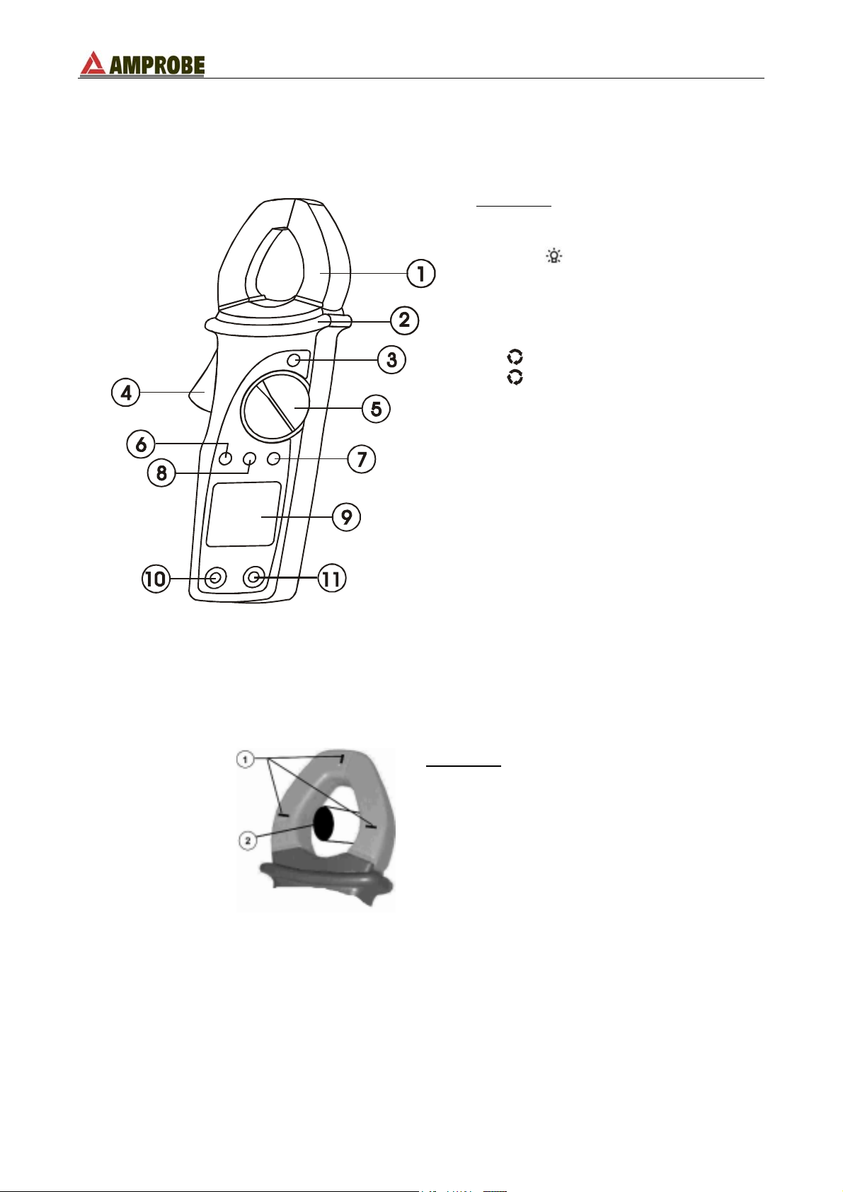
4.1.1. Controls description
LEGEND:
1. Inductive clamp jaw.
2. Safety guard.
3. D-H,
4. Jaw trigger.
5. Rotary selector switch.
6. ENERGY key (ACD-51HP)
ENERGY / H↑ key (ACD-56HPQ)
7.
56HPQ)
8. MAX/MIN/PK key (ACD-51HP)
MAX/MIN/PK / H↓ key (ACD-
56HPQ)
9. LCD display.
10. COM jack.
11. V/Ω jack.
key.
FUNC key (ACD-51HP)
FUNC / HARM key (ACD-
Fig. 1: Instrument description
4.1.2. Alignment marks
Put the conductor within the jaws on intersection of the indicated marks as close as
possible (see Fig. 2) in order to meet the meter accuracy specifications.
LEGEND:
1. Alignment marks.
2. Conductor.
Fig. 2: Alignment marks.
EN - 7
Page 12
ACD-51HP - ACD-56HPQ
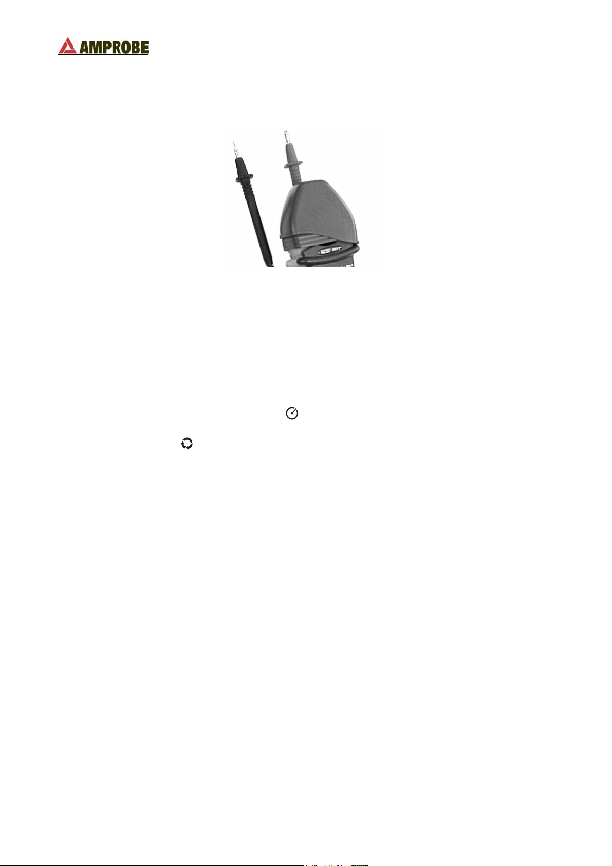
4.1.3. Rubber cap use to hold test leads
A rubber holster is provided with the instrument. This standard accessory, when fitted on
the top of the clamp, can hold one of the two test leads, as shown in Fig. 3.
Fig. 3: Use of rubber test lead holster
This rubber holster has a very practical use. It allows the user to perform the
measurements with both test leads while, more easily, observing the value on the display
at the same time.
4.1.4. AUTO POWER OFF function
In order to extend the battery life, the instrument switches off 5 minutes after the last rotary
switch or button actuation.
When this function is enabled the symbol
is displayed.
To disable this function rotate the selector to the OFF position, then rotate the selector to
any position while the
Rotating the selector switch to the OFF position then back to any function again will reenable the AUTO POWER OFF function.
FUNC key is pressed.
EN - 8
Page 13
ACD-51HP - ACD-56HPQ
4.2. DESCRIPTION OF FUNCTION KEYS
4.2.1.
This key allows the user to cycle through each function’s measurement modes with each
key press.
•
V
•
A
•
W: press
•
W3Φ: press
•
On the ACD-56HPQ model only, press & hold the
activate the “Harmonic measurement mode”. With the rotary selector switch in the
following positions
•
V
•
A
This function mode is disabled by:
• Pressing and holding the
• Rotating the selector to any other position.
More details about the
4.2.2. D-H /
This key enables the HOLD function. The symbol "H" is displayed when this function is
enabled. To disable this function:
• Press the D-H key again
• Rotate the rotary selector switch to another position.
Press and hold the
automatically turns off about 5 seconds after the last rotary selector switch or button
actuation.
4.2.3. MAX/MIN/PK key
By pressing and holding the MAX/MIN/PK key for at least 1 second, the instrument
activates the maximum (MAX), minimum (MIN), average (AVG) and peak (PK)
measurement modes. All of these values are continually updated even if only one of them
is displayed. By repeatedly pressing the MAX/MIN/PK key each value is displayed with the
corresponding frequency. To disable this function:
• Press and hold the MAX/MIN/PK key for at least 1 second.
• Rotate the selector to any position.
FUNC key
: press
: press
: press
energy, and power factor measurements on single-phase systems.
energy, and power factor measurements on three phase balanced systems.
: press and hold the
harmonic measurement. By pressing the H↑ and H↓ keys the individual
harmonic values are displayed.
: press and hold the
harmonic measurement. By pressing the H↑ and H↓ keys the individual
harmonic values are displayed.
FUNC key to select between voltage and frequency measurement.
FUNC key to select between current and frequency measurement.
FUNC key to start phase sequence detection.
FUNC key to select between active energy, reactive energy, apparent
FUNC key to select between active energy, reactive energy, apparent
FUNC key for at least 1 second to
FUNC key for at least 1 second to activate the voltage
FUNC key for at least 1 second to activate the current
FUNC key for at least 1 second.
FUNC key use are specified in the measurements paragraphs.
key
key for 1 second to illuminate the backlight. The backlight
EN - 9
Page 14

ACD-51HP - ACD-56HPQ
4.2.4. ENERGY key
With the rotary selector on “W" or "W3Φ" position, press and hold this key at least 1
second to activate the energy measurement. With the rotary selector switch in the
following positions:
•
W: push the ENERGY key to start the active energy, reactive energy, apparent
energy and power factor measurements on single-phase systems. Pushing
FUNC key every single parameter value is displayed.
W3Φ: push the ENERGY key to start the active energy, reactive energy, apparent
•
energy and power factor measurements on three phase-balanced systems.
Pushing
FUNC key every parameter value is displayed.
EN - 10
Page 15
ACD-51HP - ACD-56HPQ
4.3. DESCRIPTION OF ROTARY SWITCH FUNCTIONS
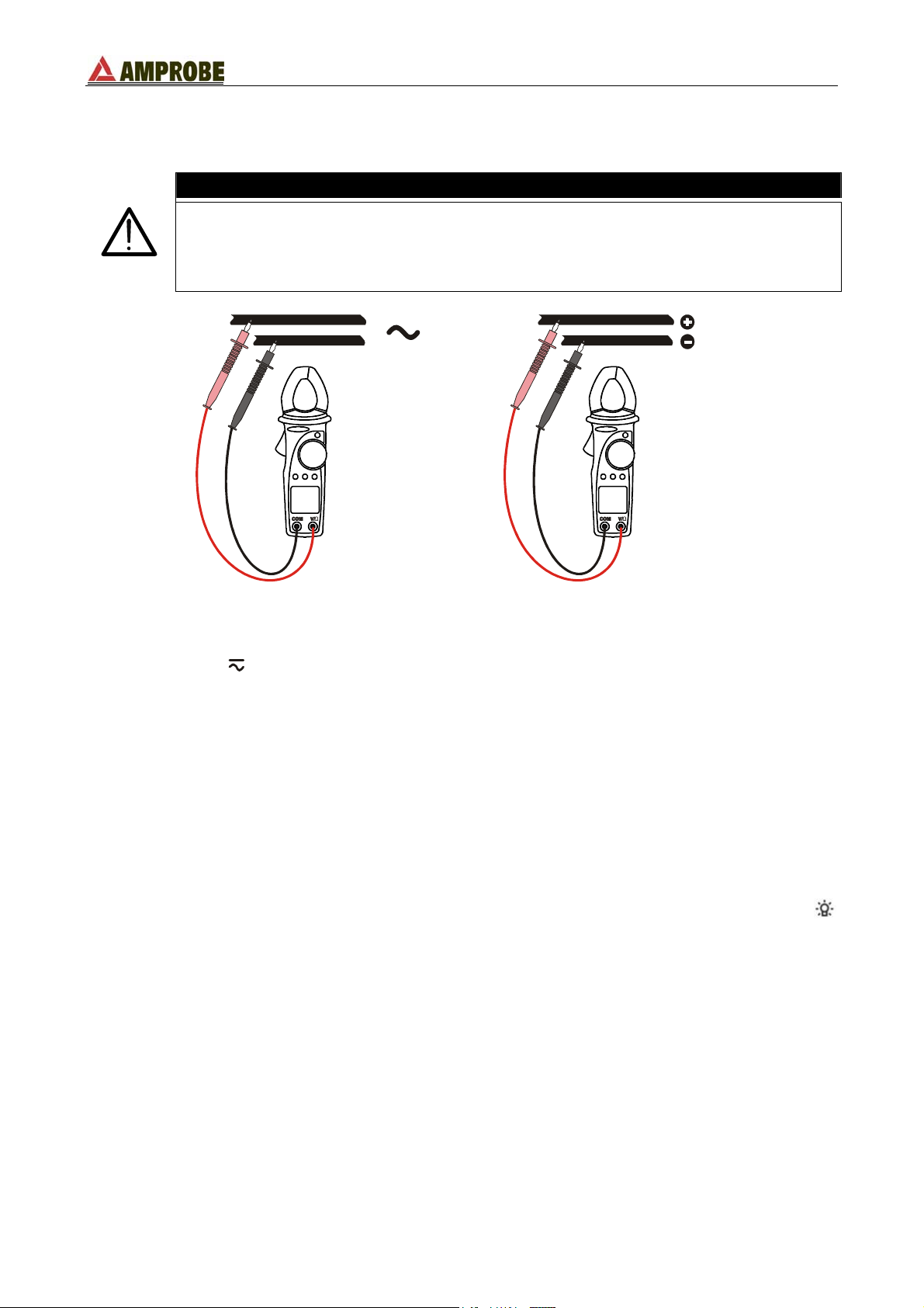
4.3.1. AC / DC voltage measurement
WARNING
• The maximum Voltage input is 600V. Do not attempt to take any voltage
measurements exceeding the limits indicated in this manual. Exceeding
the limits could cause electrical shock or damage to the instrument.
• The instrument won’t measure any value less than 1.5V.
Fig. 4: AC voltage measurement Fig. 5: DC voltage measurement
1. Select the “V
” position.
2. Insert the red lead into V/Ω jack and the black lead into the COM jack. For ease of use,
attach the rubber holster and insert a test lead (see Fig. 3).
3. Connect the test leads to the circuit under test (see Fig. 4 and Fig. 5). The instrument
automatically selects AC or DC. For AC voltage measurements the frequency value is
shown on the secondary display.
4. The “-“ symbol indicates a negative DC voltage polarity.
5. The "
O.L" symbol indicates a voltage higher than the full-scale capability of the
instrument.
6. If the displayed value varies rapidly and reading it is difficult, press the D-H key to hold
the displayed value. To disable this function press the D-H key again.
7. If the measurement is being performed in a dark environment, press and hold the
key for 1 second to activate the backlight. It automatically turns OFF after 5 seconds.
By pressing and holding the MAX/MIN/PK key for at least 1 second, the instrument
enables the maximum (MAX), minimum (MIN), average (AVG) and peak (PK)
measurement recording mode. All of these values are continually updated even if only one
is shown. Momentary MAX/MIN/PK keystrokes will cycle the display through these
recorded values with their corresponding frequencies. To disable this function press and
hold the MAX/MIN/PK key for at least 1 second or turn the selector to any other position.
EN - 11
Page 16

ACD-51HP - ACD-56HPQ
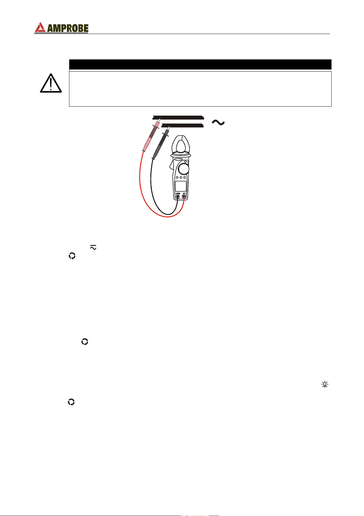
4.3.2. Frequency measurement (with test leads)
WARNING
• The maximum Voltage input is 600V. Do not attempt to take any voltage
measurements exceeding the limits indicated in this manual. Exceeding
the limits could cause electrical shock or damage to the instrument.
• The instrument won’t measure any value less than 1.5V.
Fig. 6: frequency measurement with test leads
1. Select the “
2. Press the
V
” position.
FUNC key to select the Hz function (in AC mode). Press the
FUNC
key again to return to the voltage measurement function.
3. Insert the red plug into V/Ω jack and the black plug into the COM jack. For ease of use,
attach the rubber holster and insert a test lead (see Fig. 3).
4. Connect the test leads to the circuit under test (see Fig. 6). The measured frequency
value is displayed.
5. The "O.L" symbol indicates a voltage higher than the full-scale capability of the
instrument.
6. If the display is difficult to read, press D-H key to hold the measured value. To disable
this function press the D-H key again.
7. If the measurement is being performed in a dark environment, press the
key for at
least 1 second to activate the backlight. It automatically turns OFF after 5 seconds.
By pressing and holding the MAX/MIN/PK key for at least 1 second, the instrument
enables the maximum (MAX), minimum (MIN), average (AVG) and peak (PK)
measurement recording mode. All of these values are continually updated even if only one
is shown. Momentary MAX/MIN/PK keystrokes will cycle the display through these
recorded values with their corresponding frequencies. To disable this function press and
hold the MAX/MIN/PK key for at least 1 second or turn the selector to any other position.
EN - 12
Page 17
ACD-51HP - ACD-56HPQ
4.3.3. Measurement of voltage harmonics (ACD-56HPQ only)
WARNING
• The maximum Voltage input is 600V. Do not attempt to take any voltage
measurements exceeding the limits indicated in this manual. Exceeding
the limits could cause electrical shock or damage to the instrument.
• Harmonic voltage measure is active for AC voltage on inputs only.
Fig. 7: voltage harmonic analysis
1. Select the “
V
” position.
2. Press FUNC key and keep it pressed at least 1 second until symbol “THD%” is
displayed.
3. Insert the red plug into V/Ω jack and the black plug into COM jack. For ease of use,
attach the rubber test lead holster and insert a test lead (see Fig. 3).
4. Connect the test leads to the circuit under test (see Fig. 6). The instrument displays the
Total Harmonic Distortion value of the input signal. The symbol “THD%” is shown on
the display. See chapter 0 for the parameter’s definition.
5. With the H↑ and H↓ keys you can cycle through all available harmonic values from DC
to the 25
th
order. On the secondary display is shown the order of the harmonic whose
percentage value is displayed on the main one (ex. H3% means third harmonic).
6. Press the
DC to 25
FUNC key to switch to the absolute harmonics’ values displaying (from
th
order). On the secondary display is shown the order of the harmonic whose
absolute value is displayed on the main one (ex. H3 means third harmonic).
7. If the display is difficult to read, press D-H key to hold the measured value. To disable
this function press the D-H key again.
8. If the measurement is being performed in a dark environment, press and hold the
key for 1 second to activate the backlight. It automatically turns OFF after 5 seconds.
9. Press FUNC key to escape this mode going back to voltage measurement function
(see paragraph 4.3.1).
EN - 13
Page 18

ACD-51HP - ACD-56HPQ
4.3.4. Resistance and continuity measurement
WARNING
Before attempting any resistance measurement remove the power from the
circuit under test and discharge all the capacitors, if present.
Fig. 8: resistance and continuity measurements
1. Select the “Ω ” position.
2. Insert the red plug into V/Ω jack and the black plug into COM one. For an easy
measurement use the rubber test lead holster inserting in it one test lead (see Fig. 3).
3. Connect the test leads to the circuit under test (see Fig. 8). The measured resistance
value is displayed.
4. An audible beep sounds when the measured value is lower than 40Ω.
5. The symbol "
O.L" means that the measured voltage is higher than the full scale of the
instrument.
6. If the display is difficult to read, press D-H key to hold the measured value. To disable
this function press the D-H key again.
7. If the measurement is being performed in a dark environment, press and hold the
key for 1 second to activate the backlight. It automatically turns OFF after 5 seconds.
By pressing and holding the MAX/MIN/PK key at least for 1 second, the instrument
activates the maximum (MAX), minimum (MIN) and average (AVG) measurements. All
these values are continually updated even if only one of them is shown. With a simple
MAX/MIN/PK key press the values are cyclically displayed. To escape this function press
and hold pressed MAX/MIN/PK key at least for 1 second or turn the selector to any
position.
EN - 14
Page 19

ACD-51HP - ACD-56HPQ
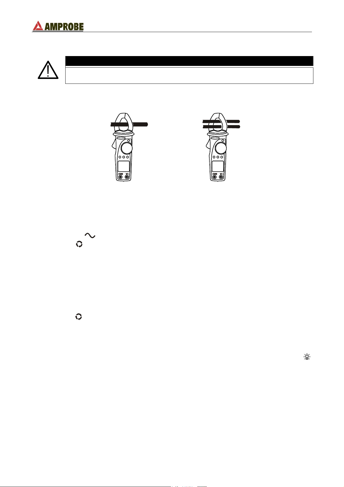
4.3.5. AC current measurement
Before attempting any measurement disconnect all the test leads from the
circuit under test and from the meter's input terminals.
WARNING
CORRECT
INCORRECT
Fig. 9: AC current measurements
1. Select the “
A
position.
”
2. Open the jaws and clamp only one cable. Pay attention to the alignment marks (see
paragraph 4.1.2. and Fig. 9). The values of current and frequency are shown on the
main and secondary displays.
3. The symbol "
O.L" means that the measured voltage is higher than the full scale of the
instrument.
4. If the display is difficult to read, press the D-H key to hold the measured value. To
disable this function press the D-H key again.
5. If the measurement is being performed in a dark environment, press and hold the
key for 1 second to activate the backlight. It automatically turns OFF after 5 seconds.
By pressing and holding the MAX/MIN/PK key at least for 1 second, the instrument
activates the maximum (MAX), minimum (MIN), average (AVG) and peak (PK)
measurements. All of these values are continually updated even if only one of them is
displayed. With a simple MAX/MIN/PK key press the values are cyclically displayed
including frequency (except for peak measurements which maximum value’s frequency is
associated to). To escape this function press and hold the MAX/MIN/PK key at least for 1
second or turn the selector to any other position.
EN - 15
Page 20

ACD-51HP - ACD-56HPQ
4.3.6. Frequency measurement (from the jaws)
WARNING
Before attempting any measurement disconnect all the test leads from the
circuit under test and from the meter's input terminals.
CORRECT
INCORRECT
Fig. 10: frequency measurements from the jaws
1. Select the “
A
position.
”
2. Press FUNC key to select Hz function.
3. Open the jaws and clamp only one cable. Pay attention to the alignment marks (see
paragraph 4.1.2. and Fig. 10). The value of frequency is shown on main display.
4. The symbol "O.L" means that the measured voltage is higher than the full scale of the
instrument.
5. If the display is difficult to read, press D-H key to hold the measured value. To disable
this function press the D-H key again.
6. If the measurement is being performed in a dark environment, press and hold the
key for 1 second to activate the backlight. It automatically turns OFF after 5 seconds.
7. Press
FUNC key to escape this mode going back to current measurement function
(see paragraph 4.3.5).
By pressing and holding pressed MAX/MIN/PK key at least for 1 second, the instrument
activates the maximum (MAX), minimum (MIN) and average (AVG) measurements. All of
these values are continually updated even if only one of them is shown. With a simple
MAX/MIN/PK key press the values are cyclically displayed. To escape this function press
and hold the MAX/MIN/PK key at least for 1 second or turn the selector to any position.
EN - 16
Page 21
ACD-51HP - ACD-56HPQ
4.3.7. Measurement of current harmonics (ACD-56HPQ only)
WARNING
Before attempting any measurement disconnect all the test leads from the
circuit under test and from the meter's input terminals.
CORRECT
INCORRECT
Fig. 11: harmonic current measurement
1. Select the “
A
position.
”
2. Press the FUNC key and keep it pressed at least 1 second until symbol “THD%” is
displayed.
3. Open the jaws and clamp only one cable. Pay attention to the alignment marks (see
paragraph 4.1.2. and Fig. 11). The instrument displays the Total Harmonic Distortion
value of the input signal. The symbol “THD%” is displayed. See chapter 0 for the
parameter’s definition.
4. With the H↑ and H↓ keys you can cycle through all available harmonic values from the
st
1
to the 25th order. On the secondary display is shown the order of the harmonic
whose percentage value is displayed on the main one (ex. H3% means third harmonic).
5. Press the
to 25
th
order). The secondary display indicates the order of the harmonic whose
FUNC key to switch to the absolute harmonics’ values displaying (from 1st
absolute value is displayed on the main one (ex. H3 means third harmonic).
6. If the display is difficult to read, press D-H key to hold the measured value. To disable
this function, press the D-H key again.
7. If the measurement is being performed in a dark environment, press and hold the
key for 1 second to activate the backlight. It automatically turns OFF after 5 seconds.
EN - 17
Page 22
ACD-51HP - ACD-56HPQ
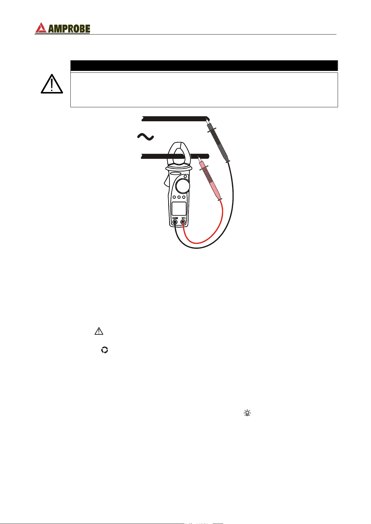
4.3.8. Power measurements on single phase systems
WARNING
The maximum input for Voltage measurements is 600V. Do not attempt to
take any voltage measurement exceeding the limits indicated in this manual.
Exceeding the limits could cause electrical shock at the operator and
damages to the clamp meter.
Fig. 12: power and energy measurement on single phase systems
1. Select the “
W” position.
2. Open the jaws and clamp only one cable. Pay attention to the alignment marks (see
paragraph 4.1.2. and Fig. 12).
3. Insert the red plug into V/Ω jack and the black plug into COM one.
4. Connect the test leads to the circuit under test (see Fig. 12). The measured active
power value and the symbol “AC” are displayed.
5. If the symbol "
" is displayed the input voltage and/or current value is higher than the
instrument’s full scale. Therefore the power and power factor values could be incorrect.
6. By pressing the
FUNC key the following parameters are shown:
• Active power (kW);
• Reactive power (kVAR, capacitive C, inductive I);
• Apparent power (kVA);
• Power factor (Pfi or Pfc for inductive and capacitive respectively).
7. If reading the display is difficult, press the D-H key to hold the value. To disable this
function press D-H key again.
8. If the measuring in a dark environment, press and hold the key for at least 1 second
to activate the backlight. It automatically turns OFF after 5 seconds.
By pressing and holding the MAX/MIN/PK key for at least 1 second, the instrument
activates the maximum (MAX), minimum (MIN) and average (AVG) measurements. All
these values are continually updated even if only one of them is displayed. With a simple
MAX/MIN/PK key press the values are cyclically displayed. To escape this function press
and hold the MAX/MIN/PK key at least for 1 second or turn the selector to any position.
EN - 18
Page 23

ACD-51HP - ACD-56HPQ
4.3.8.1. Energy measurements on single phase systems
1. Select the “
2. Open the jaws and clamp only one cable. Pay attention to the alignment marks (see
paragraph 4.1.2. and Fig. 12).
3. Insert the red plug into V/Ω jack and the black plug into COM one.
4. Connect the test leads to the circuit under test (see Fig. 12). The measured active
power value and the symbol “AC” are displayed.
5. If the symbol " " is displayed the input voltage and/or current value is higher than the
instrument’s full scale. Therefore the power and power factor values could be incorrect.
6. Press and hold the ENERGY key for at least 1 second to active the energy
measurement mode.
7. By pressing the
• Active energy (kWh);
• Reactive energy (kVARh, capacitive C, inductive I);
• Apparent energy (kVAh);
• TIME with indication of energy measurement duration.
8. Press the ENERGY key to activate the energy measurement. The message
“MEASURING” appears at the bottom of the display. Press the ENERGY key again to
stop the energy measurement, the message “MEASURING“ disappears from the
display.
9. If the reading were difficult, press D-H key to hold the obtained value. To escape this
function press the D-H key again.
10. If the measurement was performed in dark environments, press and hold the
least for 1 second to activate the backlight that is automatically turned OFF after 5
seconds.
11. Push ENERGY key and keep it pressed at least 1 second to escape from the energy
measurement mode.
W” position.
FUNC key the following parameters are displayed:
key at
EN - 19
Page 24

ACD-51HP - ACD-56HPQ
4.3.9. Power measurements on three phase balanced systems
WARNING
The maximum input for Voltage measurements is 600V. Do not attempt to
take any voltage measurement exceeding the limits indicated in this manual.
Exceeding the limits could cause electrical shock at the operator and
damages to the clamp meter.
L1
L2
L3
Fig. 13: power and energy measurement on three phase balanced systems
1. Select the “
W3Φ” position.
2. Open the jaws and clamp the L3 phase cable. Pay attention to the alignment marks
(see paragraph 4.1.2. and Fig. 13).
3. Insert the red plug into V/Ω jack and the black plug into COM one.
4. Connect the red test lead to L1 phase conductor and the black test lead to L2 phase
conductor (see Fig. 13). The measured active power value and the symbol “AC” are
displayed.
5. If the symbol " " is displayed the input voltage and/or current value is higher than the
instrument’s full scale. Therefore the power and power factor values could be incorrect.
6. By pressing the
FUNC key the following parameters are displayed:
• Active power (kW);
• Reactive power (kVA
R
, capacitive C, inductive I);
• Apparent power (kVA);
• Power factor (Pfi or Pfc for inductive and capacitive respectively).
7. If the reading were difficult, press D-H key to hold the obtained value. To escape this
function press the D-H key again.
8. If the measurement was performed in dark environments, press at least for 1 second
the
key to activate the backlight that is automatically turned OFF after 5 seconds.
By pressing and holding the MAX/MIN/PK key for at least 1 second, the instrument
activates the maximum (MAX), minimum (MIN) and average (AVG) measurements. All
these values are continually updated even if only one of them is displayed. With a simple
MAX/MIN/PK key press the values are cyclically displayed. To escape this function press
and hold the MAX/MIN/PK key at least for 1 second or turn the selector to any position.
EN - 20
Page 25

ACD-51HP - ACD-56HPQ
4.3.9.1. Energy measurement on three phase balanced systems
1. Select the “
2. Open the jaws and clamp the L3 phase cable. Pay attention to the alignment marks
(see paragraph 4.1.2. and Fig. 13).
3. Insert the red plug into V/Ω jack and the black plug into COM one.
4. Connect the red test lead to L1 phase conductor and the black test lead to L2 phase
conductor (see Fig. 13). The measured active power value and the symbol “AC” are
displayed.
5. If the symbol "
instrument’s full scale. Therefore the power and power factor values could be incorrect.
6. Push ENERGY key and keep it pressed at least 1 second to active the energy
measurement.
7. By pressing the
• Active energy (kWh);
• Reactive energy (kVARh, capacitive C, inductive I);
• Apparent energy (kVAh);
• TIME with indication of energy measurement duration.
8. Press the ENERGY key to activate the energy measurement. The counter is activated
and the message “MEASURING” is showed on the bottom of the display. Press again
ENERGY key to stop the energy measurement, the message “MEASURING“
disappears from the display.
9. If the reading were difficult, press D-H key to hold the obtained value. To escape this
function press the D-H key again.
10. If the measurement was performed in dark environments, press at least for 1 second
the
11. Push the ENERGY key and keep it pressed at least 1 second to escape from the
energy measurement.
W3Φ” position.
" is displayed the input voltage and/or current value is higher than the
FUNC key the following parameters are displayed:
key to activate the backlight that is automatically turned OFF after 5 seconds.
EN - 21
Page 26

ACD-51HP - ACD-56HPQ
N
4.3.10. Detection of phase sequence
The maximum Voltage input is 600V. Do not attempt to take any voltage
measurements exceeding the limits indicated in this manual. Exceeding the
limits could cause electrical shock or damage to the instrument.
WARNING
N
L1
L2
L3
1
1
2
L1
L2
L3
2
Fig. 14: phase rotation detection Fig. 15: phase rotation detection with rubber cup
1. Select the “
” position.
2. Insert the red lead into V/Ω jack.
3. The symbol “
1PH” will appear on the secondary display. The instrument is ready to
perform the first measurement.
st
4. Connect the red terminal to the L1 phase conductor (see Fig. 14, 1
necessary use the rubber test lead holster and insert the red test lead (see Fig. 15, 1
measurement). If
st
measurement).
WARNING
During this measurement:
• The instrument must be held in the operator’s hand.
• The test lead cable must not be in contact with or near to any voltage
source that, due to instrument sensitivity, can abort the measurement.
5. When an input voltage greater than 80V is detected the buzzer sounds and the symbol
PH” is shown on the main display. Don’t press any key and keep the test lead
“
connected to L1 phase cable.
WARNING
If the input voltage value is less to 80V the instrument doesn’t show “PH”
symbol and it’s not possible to execute the phase rotation detection.
EN - 22
Page 27

ACD-51HP - ACD-56HPQ
6. After about one second “MEASURING“ appears on the display indicating that the
instrument is ready to execute the first measurement.
7. Press the FUNC key, the “MEASURING” message will disappear.
8. Disconnect the test lead and the symbol “2PH” appears on the secondary display, the
instrument is ready to perform the second measurement.
9. Connect the test lead to the L2 phase conductor (see Fig. 14, 2
nd
measurement or Fig.
15, 2nd measurement).
10. When an input voltage greater than 80V is detected the buzzer sounds and the
symbols “PH” is shown on the main display. Don’t press any key and keep the test
lead connected to L2 phase cable.
WARNING
If the input voltage value is less to 80V instrument doesn’t show “PH”
symbol and it’s not possible to execute the phase rotation detection.
11. After about one second “MEASURING“ appears on the display indicating that the
instrument is ready to execute the second measurement.
12. Press the
FUNC key, the “MEASURING” message will disappear.
If you Wait more than 10 seconds between the first
the second, the instrument will display the “SEC” message and it’s
necessary to repeat all the measurements from the beginning. Rotate the
WARNING
FUNC key press and
selector to any position to escape the function and restart at step 1.
13. If the two tested phases follow the correct sequence, the instrument displays “1.2.3.”,
otherwise it displays “2.1.3.” indicating an incorrect phase sequence.
WARNING
• The detected voltage is NOT the phase to neutral voltage, but the
voltage between the conductor and the operator who is holding the
instrument. This value can be lower than the phase to neutral voltage.
DON’T TOUCH THE PHASE CABLE IF YOU AREN’T SURE THAT
ANY VOLTAGE IS PRESENT.
• If the operator is insulated from the ground (e.g. insulated floors, shoes
with rubber souls, etc.) the instrument may not measure correctly. We
recommend repeating test at least twice due to verify the rightness of the
obtained result.
EN - 23
Page 28

ACD-51HP - ACD-56HPQ
4.3.10.1. Detection of phase coincidence
The purpose of this measurement is to verify the correct phase between 2 conductors
before executing a parallel connection.
WARNING
The maximum Voltage input is 600V. Do not attempt to take any voltage
measurements exceeding the limits indicated in this manual. Exceeding the
limits could cause electrical shock or damage to the instrument.
L3
L2
L1
L3
L2
L1
L3
L2
L1
L3
L2
L1
1
1
2
2
Fig. 16: phase detection Fig. 17: phase detection with rubber cup
1. Select the “
” position.
2. Insert the red plug into V/Ω jack.
3. The symbol “
1PH” is shown on the secondary display, the instrument is ready to
perform the first measurement.
st
4. Connect the red terminal to the L1 phase conductor (see Fig. 16, 1
necessary use the rubber cup to insert red test lead (see Fig. 17, 1
measurement). If
st
measurement).
WARNING
During this measurement:
• The instrument must always be held in the operator’s hand.
• The test lead cable must not be in contact with or near to any voltage
source that, due to instrument sensitivity, can abort the measurement.
5. When an input voltage greater than 80V is detected the buzzer sounds and the
symbols “PH” is shown on the main display. Don’t press any key and keep the test
lead connected to L1 phase cable.
WARNING
If the input voltage value is less to 80V the instrument doesn’t show the
PH” symbol and it’s not possible to execute the phase rotation detection.
“
EN - 24
Page 29
ACD-51HP - ACD-56HPQ
6. After about one second “MEASURING“ appears on the display indicating that the
instrument is ready to execute the first measurement.
7. Press the FUNC key, the “MEASURING” symbol will disappear.
8. Disconnect the test lead. The symbol “2PH” appears on the secondary display. The
instrument is now ready to perform the second measurement.
9. Connect the test lead to the second cable (see Fig. 14, 2
nd
measurement or Fig. 15, 2nd
measurement).
10. When an input voltage greater than 80V is detected the buzzer sounds and the
symbols “PH” is shown on the main display. Don’t press any key and keep the test
lead connected to L2 phase cable.
WARNING
If the input voltage value is less to 80V instrument doesn’t show “PH”
symbol and its not possible to execute the phase rotation detection.
11. After about one second “MEASURING“ appears indicating the instrument is ready to
execute the second measurement.
12. Press the
FUNC key, the “MEASURING” symbol disappears.
If you Wait more than 10 seconds between the first
the second, the instrument will display the “SEC” message and it’s
necessary to repeat all the measurements from the beginning. Rotate the
WARNING
FUNC key press and
selector to any position to escape the function and restart at step 1.
13. If the two test cables belong to the same phase, the instrument displays “1.1.-.”,
otherwise it displays “2.1.3.” or “1.2.3.” This indicates that the two cables belong to
two different phases.
WARNING
• The detected voltage is NOT the phase to neutral voltage, but the
voltage between the conductor and the operator who is holding the
instrument. This value can be lower than the phase to neutral voltage.
DON’T TOUCH THE PHASE CABLE IF YOU AREN’T SURE THAT
ANY VOLTAGE IS PRESENT.
• If the operator is insulated from the ground (e.g. insulated floors, shoes
with rubber souls, etc.) the instrument may not measure correctly. We
recommend repeating test at least twice due to verify the rightness of the
obtained result.
EN - 25
Page 30

ACD-51HP - ACD-56HPQ
4.3.10.2. Phase detection
The maximum Voltage input is 600V. Do not attempt to take any voltage
measurements exceeding the limits indicated in this manual. Exceeding the
limits could cause electrical shock or damage to the instrument.
WARNING
Fig. 18: Voltage detection Fig. 19: Voltage detection with rubber cup
1. Select the “
” position.
2. Insert the red plug into V/Ω jack.
3. Connect the red terminal to the L1 phase conductor (see Fig. 18, 1
necessary use the rubber cup to insert red test lead (see Fig. 19, 1
st
measurement). If
st
measurement).
4. When an input voltage greater than 80V is detected the buzzer emits a sound and the
symbols “
PH” is shown on the main display.
WARNING
During this measurement:
• The instrument must be held in the operator’s hand.
• The test lead cable must not be in contact with or near to any voltage
source that, due to instrument sensitivity, can abort the measurement.
WARNING
• The detected voltage is NOT the phase to neutral voltage, but the
voltage between the conductor and the operator who is holding the
instrument. This value can be lower than the phase to neutral voltage.
DON’T TOUCH THE PHASE CABLE IF YOU AREN’T SURE THAT
ANY VOLTAGE IS PRESENT.
• If the operator is insulated from the ground (e.g. insulated floors, shoes
with rubber souls, etc.) the instrument may not measure correctly. We
recommend repeating test at least twice due to verify the rightness of the
obtained result.
EN - 26
Page 31
ACD-51HP - ACD-56HPQ
5. MAINTENANCE
5.1. GENERAL INFORMATION
1. This digital clamp meter is a precision instrument. Whether in use or in storage, please
do not exceed the specifications to avoid any possible damage or danger during use.
2. Do not place this meter in high temperature and/or humidity or expose to direct
sunlight.
3. Be sure to turn the meter off after use. For long term storage, remove the batteries to
avoid leakage of battery fluid that can damage the internal components.
5.2. BATTERY REPLACEMENT
When the LCD displays the "
Only experts and trained technicians should perform this operation. Remove
the test leads or the circuit under test before replacing the batteries.
1. Turn the rotary switch to the OFF position.
2. Disconnect the test leads from the jacks and any cable from the jaws.
3. Unscrew the battery cover screw and remove the cover.
4. Replace the batteries with two new AAA batteries. Pay attention to the correct polarity.
5. Replace the battery cover and it’s screw.
6. Use the appropriate battery disposal methods for your area.
5.3. CLEANING
To clean the instrument, use a soft dry cloth. Never use a wet cloth, solvents or water, etc.
" symbol, replace the batteries.
WARNING
EN - 27
Page 32

ACD-51HP - ACD-56HPQ
6. TECHNICAL SPECIFICATIONS
6.1. CHARACTERISTICS
Accuracy is indicated as [% of reading + digit number]. It is referred to the following
reference conditions: 23°C ± 5°C with RH <75%.
DC Voltage
Range Resolution Accuracy Input impedance
1.6 ÷ 599.9V
AC Voltage (TRMS)
Range Resolution
1.6 ÷ 599.9V
Max. Crest factor = 1.5
MAX / MIN / AVG / PEAK AC/DC Voltage
Function Range Resolution Accuracy Response time
MAX,MIN,AVG
PEAK
AC Current (TRMS)
Range Resolution
0.0 ÷ 399.9A
Max. Crest factor = 2
MAX / MIN / AVG / PEAK AC Current
Function Range Resolution Accuracy
MAX,MIN,AVG
PEAK
Resistance and Continuity test
Range Resolution Accuracy Overload protection
0.0 ÷ 499.9Ω 0.1Ω
500 ÷ 999Ω 1Ω
1000 ÷ 1999Ω 3Ω
Instrument emitted a buzzer for R<40Ω
Frequency (with test leads)
Range Resolution Accuracy Overload protection
40.0 ÷ 399.9Hz
Voltage range for frequency measure: 0.5 ÷ 600V
Frequency (with jaws)
Range Resolution Accuracy Overload protection
40.0 ÷ 399.9Hz
Voltage range for frequency measure: 0.5 ÷ 400V
Active power, Reactive power, Apparent power
Range [kW], [kVAR], [kVA] Resolution [kW], [kVAR], [kVA] Accuracy
0.00 ÷ 99.99
100.0 ÷ 999.9
Accuracy defined for: sine wave, voltage 100 ÷600V, current ≥1A, freq. 50-60Hz, Pf: 0.8i ÷ 0.8c
0.1V
0.1V
10 ÷ 599.9V
10 ÷ 850V
0.1A
1.0 ÷ 399.9A
10 ÷ 800A
0.1Hz
0.1Hz
±(1.0% rdg + 3 dgt) 1MΩ
Accuracy
40 ÷ 200Hz 200 ÷ 400Hz
Input impedance
±(1.0% rdg+3 dgt) ±(5.0% rdg + 3 dgt) 1MΩ
0.1V
1V
±(5.0% rdg + 10 dgt)
±(5.0% rdg + 10 dgt)
Accuracy
40 ÷ 200Hz 200 ÷ 400Hz
±(1.0% rdg+3 dgt) ±(5.0% rdg + 5 dgt)
Overload protection
500ms
1ms
600A RMS
Response
0.1A
1A
±(5.0% rdg + 10 dgt)
±(5.0% rdg + 10 dgt)
±(1.0% rdg + 5 dgt)
±(0.5% rdg + 1 dgt)
±(0.5% rdg + 1 dgt)
0.01
0.1
time
500ms 600A RMS
15ms 600A RMS
600V AC/DC RMS
600V RMS
600A RMS
±(3.5% rdg + 3 dgt)
protection
Overload
EN - 28
Page 33

ACD-51HP - ACD-56HPQ
Power factor
Range Resolution Accuracy Minimum current
0.20 ÷ 1.00
Voltage and current harmonics (ACD-56HPQ only)
Harmonic order Resolution [V], [A] Accuracy
1 ÷ 15
16 ÷ 25
Accuracy defined for: voltage ≥1.6V, current ≥2A
0.01
0.1
0.1
± 3°
±(10.0% rdg + 5 dgt)
±(15.0% rdg + 5 dgt)
2A
6.1.1. Safety standards
Comply with: EN 61010
Insulation: Class 2, double reinforced insulation
Pollution: Level 2
For inside use, max height: 2000m
Over voltage: CAT III 600V between terminals and ground
6.1.2. General data
Mechanical characteristics
Size: 205 (L) x 64 (W) x 39 (D) mm
Weight (including battery): about 280g batteries included
Jaws opening: 30mm
Max conductor size: 30mm
Power supply
Battery type: 2 batteries 1.5V LR03 AAA.
Low battery indication: Symbol "
" is displayed when battery level is too low.
Battery life: About 90 hours of continue measurement
Display
Characteristics: 4 dgt LCD with maximum reading 9999 units plus decimal
point and sign
Sample rate: 64 samples in 20ms
Conversion mode: TRMS
6.2. ENVIRONMENTAL CONDITIONS
6.2.1. Climatic conditions
Reference temperature: 23° ± 5°C
Operating temperature: 5 ÷ 40 °C
Operating humidity: <80% RH
Storage temperature: -10 ÷ 60 °C
Storage humidity: <80% RH
6.2.2. EMC
This apparatus was designed in accordance with EMC standards in force and its
compatibility has been tested in accordance EN61326 (1997) + A1 (1998) + A2 (2001).
This product conforms to the prescriptions of the European directive on low voltage
73/23/EEC (LVD) and to EMC directive 89/336/EEC, amended by 93/68/EEC.
6.3. ACCESSORIES
6.3.1. Standard accessories
The accessories contained inside the packaging are the following:
• Instrument • Rubber holster (MTL-CAP)
• Test leads (MTL-90B) • Alligator clips
• Carrying Case (SV-U) • User’s manual
EN - 29
Page 34

ACD-51HP - ACD-56HPQ
7. WARRANTY
Congratulations! Your new instrument has been quality crafted according to quality
standards and contains quality components and workmanship. It has been inspected for
proper operation of all of its functions and tested by qualified factory technicians according
to the long-established standards of our company.
Your instrument has a limited warranty against defective materials and/or workmanship for
1 year from the date of purchase provided that, in the opinion of the factory, the instrument
has not been tampered with or taken apart.
Should your instrument fail due to defective materials, and/or workmanship during
this 1 year period, a no charge repair or replacement will be made to the original
purchaser. Please have your dated bill of sale, which must identify the instrument
model number and serial number and call the number listed below:
Repair Department
ATP – Amprobe, TIF, Promax
Miramar, FL
Phone: 954-499-5400
800-327-5060
Fax: 954-499-5454
Website: www.amprobe.com
Please obtain an RMA number before returning product for repair.
Outside the U.S.A. the local representative will assist you. Above limited warranty covers
repair and replacement of instrument only and no other obligation is stated or implied.
EN - 30
Page 35

ACD-51HP - ACD-56HPQ
8. APPENDIX: VOLTAGE AND CURRENT HARMONICS
8.1. THEORY
Any periodical non-sine wave can be represented as a sum of sinusoidal waveforms each
having a frequency that corresponds to an integer multiple of the fundamental frequency,
according to the relation:
∞
)tsin(VVv(t)
ϕω
++=
kk
(1)
previous components.
where:
V
= Average value of v(t)
0
V
= Amplitude of the fundamental of v(t)
1
V
= Amplitude of the kth harmonic of v(t)
k
∑
=
k0
1k
LEGENDA:
1. Fundamental
2. Third Harmonic
3. Distorted waveform sum of two
Effect of the sum of 2 multiple frequencies.
In the mains voltage, the fundamental has a frequency of 60 Hz, the second harmonic has
a frequency of 120 Hz, the third harmonic has a frequency of 180 Hz and so on. Harmonic
distortion is a constant problem and should not be confused with short durations events
such as sags, surges or spikes.
It can be noted that in (1) the index of sigma is from 1 to the infinity. What happens in
reality is that a signal does not have an unlimited number of harmonics: a number always
exists after which the harmonics value is negligible. The EN 50160 standard recommends
the index end in (2) in correspondence of the 40
th
harmonic.
A fundamental element to detect the presence of harmonics is THD defined as:
40
2
V
h
∑
h
=
V
2
1
THDv
=
This index takes all the harmonics into account. The larger it is, the more distorted the
waveform gets.
EN - 31
Page 36

ACD-51HP - ACD-56HPQ
8.2. LIMIT VALUES FOR HARMONICS
EN-50160 fixes the limits for the harmonic voltages, which can be introduced into the
network by the energy provider. Under normal conditions, during whatever period of a
week, 95% if the RMS value of each harmonic voltage, for a duration of 10 minutes, will
have to be less than or equal to the values stated in the following table.
The total harmonic distortion (THD) of the supply voltage (including all the harmonics up to
the 40
th
order) must be less than or equal to 8%.
Odd harmonics Even harmonics
Not multiple of 3 Multiple of 3
Order h Relative voltage % Max Order h Relative voltage % Max
5 6 3 5 2 2
7 5 9 1,5 4 1
11 3,5 15 0,5 6..24 0,5
13 3 21 0,5
17 2
19 1,5
23 1,5
25 1,5
Order h
Relative voltage %Max
These limits, theoretically applicable only for the supplier of electric energy, provide
however a series of reference values within which the harmonics introduced into the
network by the user must be contained.
8.3. CAUSES FOR THE PRESENCE OF HARMONICS
Any apparatus that alters the sine wave or uses only a part of such a wave causes
distortions to the sine wave and therefore harmonics.
All current signals result in some way virtually distorted. The most common situation is the
harmonic distortion caused by non-linear loads such as electric household appliances,
personal computers or motor speed control drives. Harmonic distortion causes significant
currents at frequencies that are odd multiples of the fundamental frequency. Harmonic
currents affect the neutral current.
In most countries, the mains power is three-phase 50/60Hz with a delta primary and star
secondary transformers. The secondary generally provides 277V AC from phase to neutral
and 480V AC from phase to phase. Balancing the loads on each phase has always
represented a headache for electric systems designers.
Until some ten years ago, in a well balanced system, the vector sum of the currents in the
neutral was zero or quite low (given the difficulty of obtaining a perfect balance). The
devices were incandescent lights, small motors and other devices that presented linear
loads. The result was an essentially sinusoidal current in each phase and a low current on
the neutral at a frequency of 50/60Hz.
“Modern” devices such as TV sets, fluorescent lights, video machines and microwave
ovens normally draw current for only a fraction of each cycle thus causing non-linear loads
and subsequent non-linear currents. All this generates odd harmonics of the 50/60Hz line
frequency. For this reason, the current in the transformers of the distribution boxes
contains only a 50Hz (or 60Hz) component but also a 150Hz (or 180Hz) component, a
50Hz (or 300Hz) component and other significant components of harmonic up to 750Hz
(or 900Hz) and higher.
The vector sum of the currents in a well balanced system that feeds non-linear loads may
still be quite low. However, the sum does not eliminate all current harmonics. The odd
multiples of the third harmonic (called “TRIPLENS”) are added together in the neutral
conductor and can cause overheating even with balanced loads.
EN - 32
Page 37

ACD-51HP - ACD-56HPQ
8.4. CONSEQUENCES OF THE PRESENCE OF HARMONICS
In general, even harmonics, i.e. the 2
nd
, 4th etc., do not cause problems.
Designers should take into consideration the following points when designing a power
distribution system that will contain harmonic current:
Installation parts Effects attributed to Harmonics
Fuses
Cables
Neutral conductor
Transformer
Motors
Heating of internal fuse elements. This over-heating can cause an explosion of the fuse casing.
Increase in “body” effect. This means, for cables with many wires, the internal wires have higher
impedance than external wires due to their inability to dissipate heat.
The consequence of this is the current, which normally is distribute along the external surface of
wire, produces:
– an over-heating of the conductor;
– a premature degrading of the cable’s insulation;
– an increase in line voltage drop.
The triplens harmonics, odd multiples of three, sum on the neutral conductor (instead of erasing
themselves) and generate a potential danger over-heating situation of the same conductor.
Increasing of copper loss due to a higher TRMS current value that circulate on internal circuits
and due to “body” effect present on protected wires also.
Increasing of iron loss due to hysteresis cycle distortion and due to generation of leakage
currents on magnetic core.
Heating of insulation material due to eventually DC component that can generate saturation of
magnetic core column.
Increase of loss due to over-heating of internal circuits and possible damage of insulation
material. Increase in motor vibration reducing efficiency and causing premature motor wear.
th
and 11th harmonic components generate some abnormal electromagnetic coupling that
The 5
can increase motor speed.
Re-phased
capacitance
RCD devices
Energy disk
counters
Power controls
switch
UPS
Electronics
devices
Increase in “parallel resonance” present inside a circuit, due to inductive loads and re-phased
capacitance, when at least one of the harmonics has the same frequency as the resonance
phenomenon. Effects of this event can be very dangerous. with explosion of used re-phased
capacitances.
Possible saturation of current sensing toroidal transducers resulting in incorrect measurements.
Increased rotation speed of a disk resulting in measurement error (especially in cases of low
power factor loads).
Reduce of electrical duration of contact surfaces.
Reduced power generation from UPS.
Internal damage of electronic components.
EN - 33
Page 38

ESPAÑOL
Manual de Instrucciones
Versión ES 1.03 - 30/10/2003
Page 39

ACD-51HP - ACD-56HPQ
Índice:
1. PRECAUCIONES Y MEDIDAS DE SEGURIDAD............................................................................2
1.1. Instrucciones preliminares .......................................................................................................3
1.2. Durante el uso..........................................................................................................................3
1.3. Después del uso ......................................................................................................................3
1.4. Definiciòn de categorìa de medida (sobrevoltaje) ....................................................................4
2. DESCRIPCION GENERAL ..............................................................................................................5
3. PREPARACION PARA SU USO......................................................................................................6
3.1. Control inicial ...........................................................................................................................6
3.2. Alimentaciòn del instrumento ...................................................................................................6
3.3. Calibración ...............................................................................................................................6
3.4. Almacenaje ..............................................................................................................................6
4. INSTRUCCIONES DE USO.............................................................................................................7
4.1. Descripción del instrumento.....................................................................................................7
4.1.1. Descripción de los controles....................................................................................................... 7
4.1.2. Marcas de alineación.................................................................................................................. 7
4.1.3. Uso del capuchón de goma........................................................................................................8
4.1.4. Función auto apagado (Auto Power Off).................................................................................... 8
4.2. Descripciòn de las teclas de funciòn........................................................................................9
4.2.1. Tecla
4.2.2. Tecla D-H / ........................................................................................................................... 9
4.2.3. Tecla MAX/MIN/PK................................................................................................................... 10
4.2.4. Tecla ENERGY......................................................................................................................... 10
FUNC.......................................................................................................................... 9
4.3. Descripción del selector rotativo ............................................................................................11
4.3.1. Medida de voltaje CA / CC .......................................................................................................11
4.3.2. Medida de frecuencia (a través de las puntas de prueba) ....................................................... 12
4.3.3. Medida de los armónicos de voltaje (ACD-56HPQ solo) ......................................................... 13
4.3.4. Medida de la resistencia y prueba de la continuidad ............................................................... 14
4.3.5. Medida de la corriente CA........................................................................................................ 15
4.3.6. Medida de la frecuencia (a través de las pinzas)..................................................................... 16
4.3.7. Medida de los armónicas de corriente (ACD-56HPQ solo)...................................................... 17
4.3.8. Medida de potencia en sistema monofásico ............................................................................ 18
4.3.8.1. Medida de energía en sistemas monofásicos..................................................................... 19
4.3.9. Medida de potencia en sistemas trifásicos equilibrados.......................................................... 20
4.3.9.1. Medida de energía en sistemas trifásicos equilibrados ...................................................... 21
4.3.10. Medida del sentido cíclico de las fases .................................................................................... 22
4.3.10.1. Medida de la Concordancia de Fase .................................................................................. 24
4.3.10.2. Función Busca fases ........................................................................................................... 26
5. MANTENIMIENTO .........................................................................................................................27
5.1. Generalidades........................................................................................................................27
5.2. Cambio de las pilas................................................................................................................27
5.3. Limpieza.................................................................................................................................27
6. ESPECIFICACIONES TÉCNICAS .................................................................................................28
6.1. Carateristicas técnicas...........................................................................................................28
6.1.1. Normas de seguridad ............................................................................................................... 29
6.1.2. Características generales......................................................................................................... 29
6.2. Ambiente................................................................................................................................29
6.2.1. Condiciones ambientales de uso ............................................................................................. 29
6.2.2. EMC.......................................................................................................................................... 29
6.3. Accesorios .............................................................................................................................29
6.3.1. Dotación estándar .................................................................................................................... 29
7. ASISTENCIA..................................................................................................................................30
8. ARMÒNICOS DE VOLTAJE Y CORRIENTE.................................................................................31
8.1. Teorìa.....................................................................................................................................31
8.2. Valores lìmite de los armònicos .............................................................................................32
8.3. Causas de la presencia de armónicos ...................................................................................32
8.4. Consecuencia de la presencia de armónicos.........................................................................33
ES - 1
Page 40

ACD-51HP - ACD-56HPQ
1. PRECAUCIONES Y MEDIDAS DE SEGURIDAD
Este aparato es conforme a las normas de seguridad EN 61010. Estas normas son
relativas a los instrumentos electrónicos de medida.
Para su propia seguridad y la del aparato, usted debe seguir los procedimientos descritos
en este manual de instrucciones y especialmente leer todas las notas que preceden el
símbolo
Cuando esté midiendo tome mucho cuidado en las siguientes condiciones:
• No mida voltaje o corriente en ambientes húmedos.
• No utilice el equipo en ambientes con gases explosivos (material), gases combustibles,
vapores o polvo (material).
• Manténgase aislado del objeto cuando este en medida.
• No toque ningún metal expuesto (conductivo) como las puntas de prueba, los
terminales, objetos que están bajo de evaluación, circuitos, etc.
• Conducción por el cuerpo humano pude suceder cuando se mide un voltaje más que
20V.
• Si el instrumento tiene cualquier daño como deformación, fractura, sustancias
extranjeras, pantalla rota no utilice el instrumento.
• No exceda el Guardamano con la mano durante la medidas de voltaje y/o corriente
(vea la Fig. 1, punto 2).
Los siguientes símbolos se usan para:
.
ATENCIÓN
Si el instrumento es usando sin seguir los avisos y/o las instrucciones de
uso, se pueden dañar las protecciones de seguridad.
Atención: lea el manual de instrucciones. Un uso incorrecto puede dañar al
aparato o sus componentes.
Peligro Voltaje Alto: riesgo de choque eléctrico.
Medidor de doble Aislamiento.
Voltaje o Corriente CA.
Voltaje o Corriente CC.
ES - 2
Page 41

ACD-51HP - ACD-56HPQ
1.1. INSTRUCCIONES PRELIMINARES
• Este equipo ha sido diseñado para su uso en ambientes de grado de polución 2.
• Puede ser usado para medir CORRIENTE, VOLTAJE y FRECUENCIA en
instalaciones con Categoría III hasta 600V entre Fase y Tierra (Instalaciones fijas) y
por medida de corriente hasta 400A.
• Este equipo no está diseñado para mediciones que no son sinusoidales.
• Usted debe cumplir con las regulaciones de uso para asegurar:
♦ ♦ Protegerse de corrientes eléctricas peligrosas.
Proteger el instrumento de un uso incorrecto.
• Sólo las puntas de prueba incluidas con el instrumento garantizan el cumplimiento con
las normas de seguridad. Deben estar en buen estado y si es necesario, cambiarlas
por un modelo idéntico.
• No pruebe o conecte el instrumento a ningún circuito con voltaje o coriente que
excedan la protección de sobrecarga.
• No efectuar medidas en condiciones ambientales fuera de los límites indicados en el
parágrafo 6.2.1.
• Compruebe si las pilas está instalada correctamente.
• Antes de conectar las puntas de prueba a la instalación compruebe que el selector de
funciones está en la posición requerida.
• Compruebe que el visualizador y el indicador de escala indiquen lo mismo que la
función deseada.
1.2. DURANTE EL USO
Lea las recomendaciones siguientes:
ATENCIÓN
No siguiendo los avisos y/o las instrucciones de uso pueden dañar el
instrumento y/o sus componentes o incluso lastimar al usuario.
• Cuando cambie de escala, primero desconecte el conductor que esta en medida o el
circuito de la pinzas para evitar accidentes.
• Cuando el instrumento está conectado a los circuitos de medida, nunca toque los
terminales inusitados.
• Cuando mida resistencias, por favor no añade ningún voltaje. Aunque hay un circuito
de protección, voltajes excesivos pueden llegar a provocar un funcionamiento
incorrecto.
• Cuando mida corrientes, primero desconecte las puntas de prueba de los terminales
de entrada.
• Cuando mida corrientes, cualquier corriente cercana a las pinzas pueden afectar la
precisión.
• Cuando mida corrientes, siempre ponga el conductor en el centro de la pinzas para
obtener la lectura más precisa. (vea párrafo 4.1.2).
• Durante la medida, si el valor de la lectura o el indicador de polaridad permanecen sin
cambios, compruebe si la tecla HOLD está activada.
1.3. DESPUÉS DEL USO
• Tan pronto las medidas se han completados, gire el selector de funciones a la posición
OFF.
• Si el instrumento no va ha ser usado durante un período largo, saque las pilas.
ES - 3
Page 42

ACD-51HP - ACD-56HPQ
1.4. DEFINICIÒN DE CATEGORÌA DE MEDIDA (SOBREVOLTAJE)
La norma EN61010-1: Prescripciones de seguridad para aparatos eléctricos de medida,
control y para uso en laboratorio, Parte 1: Prescripciones generales, definición de
categoría de medida, comúnmente llamada categoría de sobrevoltaje. En el párrafo 6.7.4:
Circuitos de medida, indica:
Los circuitos están subdivididos en las siguientes categorías de medida:
• La categoría IV de medida sirve para las medidas efectuadas sobre una fuente de
una instalación de baja voltaje.
Ejemplo: contadores eléctricos y de medidas sobre dispositivos primarios de
protección de las sobre corrientes y sobre la unidad de regulación de la ondulación.
• La categoría III de medida sirve para las medidas efectuadas en instalaciones
interiores de edificios.
Ejemplo: medida sobre paneles de distribución, disyuntores, cableados, incluidos
los cables, los embarrados, los interruptores, las tomas de instalaciones fijas y los
aparatos destinados al uso industrial y otros instrumentación, por ejemplo los
motores fijos con conexionado a instalación fija.
• La categoría II de medida sirve para las medidas efectuadas sobre circuitos
conectados directamente a las instalaciones de baja voltaje.
Ejemplo: medidas sobre instrumentación para uso doméstico, utensilios portátiles e
instrumentación similar.
• La categoría I de medida sirve para las medidas efectuadas sobre circuitos no
conectados directamente a la RED DE DISTRIBUCIÓN.
Ejemplo: medidas sobre no derivados de la RED y derivados de la RED pero con
protección particular (interna). En este último caso las necesidades de transitorios
son variables, por este motivo (OMISSIS) se requiere que el usuario conozca la
capacidad de resistencia a los transitorios de la instrumentación.
ES - 4
Page 43

ACD-51HP - ACD-56HPQ
2. DESCRIPCION GENERAL
Queremos agradecerle la confianza depositada. La pinza que acaba de adquirir garantiza
mediciones precisas y seguras de acuerdo con las instrucciones del presente manual., Le
garantizará medidas con precisión y fiabilidad.
El instrumento está fabricado en modo de garantizarle la máxima seguridad gracias a un
desarrollo de nueva concepción que asegura el doble aislamiento y la categoría de
sobrevoltaje III hasta 600V (ver párrafo 6.1.1).
El equipo es capaz de realizar las siguientes mediciones:
• Medida de voltaje CA (V
• Medida de voltaje CC (V
• Medida del valor de la corriente CA (ICA) en verdadero valor eficaz TRMS.
• Medida de los Armónicos (1 –25a) de Voltaje (ACD-56HPQ solo).
• Medida de los Armónicos (1 –25a) de Corriente (ACD-56HPQ solo).
• Medida de la frecuencia a través de los terminales de entrada.
• Medida de la frecuencia a través del pinzas.
• Medida de la Resistencia.
• Prueba de continuidad.
• Detección del Sentido cíclico de las Fases con una sola punta de prueba.
• Medida de la potencia activa, reactiva, aparente y factor de potencia en sistemas
monofásicos.
• Medida de la potencia activa, reactiva, aparente y factor de potencia en sistemas
trifásicos equilibrados.
• Medida de la energía activa, reactiva, aparente en sistema monofásico.
• Medida de la energía activa, reactiva, aparente en sistemas trifásicos equilibrados.
Cada unos de estos parámetros pueden ser seleccionados mediante el selector rotativo
de 7 posiciones, incluido la posición OFF. Son presentes las teclas: "
“MAX/MIN/PK”, “ENERGY” e “D-H / ” (ACD-51HP solo) y "
“MAX/MIN/PK / H↓”, “ENERGY / H↑” e “D-H / ” (ACD-56HPQ solo). Para la descripción
detallada de las varias funciones vea el capítulo 4.2. Los parámetros seleccionados
aparecen sobre el visualizador con la indicación de la unidad de medida y de las
funciones habilitadas.
) en verdadero valor eficaz TRMS.
CA
).
CC
FUNC ",
FUNC / HARM",
ES - 5
Page 44

ACD-51HP - ACD-56HPQ
3. PREPARACION PARA SU USO
3.1. CONTROL INICIAL
Todos los equipos han sido comprobados mecánicamente y eléctricamente antes de su
envío.
Han sido tomados los cuidados necesarios para asegurar que el instrumento llegue hasta
usted sin daños.
De todas formas, es aconsejable realizar una pequeña comprobación con el fin de
detectar cualquier daño posible sufrido por el transporte, si este fuera el caso, consulte
inmediatamente con su transportista.
Compruebe que dentro el empaque estén todos los componentes incluidos en la lista del
párrafo 6.3.1 En caso de discrepancias contacte con el distribuidor.
En el caso donde tengas que reenviar el equipo siga las instrucciones reflejadas en el
capitulo 7.
3.2. ALIMENTACIÒN DEL INSTRUMENTO
El instrumento está alimentado por dos pilas modelo 1.5V LR03 AAA UM-4 incluidas en el
embalaje. La vida de las pilas es de unas 90 horas.
El símbolo "
cambie las pilas como indica el párrafo 5.2.
3.3. CALIBRACIÓN
El instrumento cumple con las características listadas en este manual. Las características
de las especificaciones están garantizadas por un año.
3.4. ALMACENAJE
Para garantizar la precisión de las medidas, después de un largo tiempo de almacenaje
en condiciones ambientales extremas, espere a que el instrumento esté en las
condiciones ambientales normales (vea las especificaciones ambientales en el párrafo
6.2.1).
" aparece cuando las pilas están cerca de la descarga. En este caso
ES - 6
Page 45

ACD-51HP - ACD-56HPQ
4. INSTRUCCIONES DE USO
4.1. DESCRIPCIÓN DEL INSTRUMENTO
4.1.1. Descripción de los controles
LEYENDA:
1. Pinzas
2. Guardamanos
3. Tecla D-H /
4. Gatillo de apertura
5. Conmutador de funciones
6. Tecla ENERGY (ACD-51HP)
Tecla ENERGY/H↑ (ACD56HPQ)
7. Tecla
Tecla
56HPQ)
8. Tecla MAX/MIN/PK (ACD-51HP)
Tecla MAX/MIN/PK/H↓ (ACD56HPQ)
9. Visualizador LCD
10. Terminal COM
11. Terminal V/Ω
FUNC (ACD-51HP)
FUNC/HARM (ACD-
Fig. 1: Descripción del instrumento
4.1.2. Marcas de alineación
Coloque el conductor dentro de las pinzas y en la intersección de las marcas de
alineación lo más exactamente posible para poder obtener la precisión de las
especificaciones. (Vea. Fig. 2).
LEYENDA:
1. Marcas de Alineamiento.
2. Conductor.
Fig. 2: Marca de alineación
ES - 7
Page 46

ACD-51HP - ACD-56HPQ
4.1.3. Uso del capuchón de goma
El instrumento incluye un capuchón de goma que, insertado sobre las pinzas, permite
alojar una de las dos puntas de prueba de medida, como muestra la Fig. 3.
Fig. 3: Uso de la pinza con el capuchón de goma
Esto permite un uso muy práctico del instrumento, pudiendo operar con los 2 terminales
de medida y contemporáneamente vea el valor indicado en el visualizador del
instrumento.
4.1.4. Función auto apagado (Auto Power Off)
Con el fin de ahorrar pilas, el instrumento quedará apagado si después de 30 minutos no
se ha pulsado ninguna tecla o ha cambiado el selector de funciones. Si esta función está
desactivada aparece el símbolo
Para deshabilitar esta modalidad de funcionamiento primero apague el instrumento y
enriéndalo de nuevo presionando a la vez la tecla FUNC.
Apagando y volviendo a encender el instrumento se habilitará automáticamente la función
de AUTO APAGO.
.
ES - 8
Page 47

ACD-51HP - ACD-56HPQ
4.2. DESCRIPCIÒN DE LAS TECLAS DE FUNCIÒN
4.2.1. Tecla
Esta tecla permite conmutar entre varias modalidades de medida, que se presentan
cíclicamente a cada presión, asociada a las posiciones del conmutador rotativo. En
particular para las posiciones del conmutador:
•
V
: presionando de la tecla
• A : presionando de la tecla
•
: presionando de la tecla
FUNC
FUNC permite seleccionar la medida de voltaje y la
medida de la frecuencia de la señal en las entradas del instrumento.
FUNC permite seleccionar la medida de la
corriente que circula en el cable pinzado y la medida de frecuencia de la
misma señal.
FUNC habilita la detección del sentido cíclico de
las fases.
•
W: presionando de la tecla
FUNC permite seleccionar la medida de la
potencia activa, potencia reactiva, potencia aparente, factor de potencia en los
sistemas monofásica.
W3Φ: presionando de la tecla
•
FUNC permite seleccionar la medida de la
potencia activa, potencia reactiva, potencia aparente, factor de potencia en los
sistemas trifásicos equilibrados.
Para el modelo ACD-56HPQ, pulsar durante 1 segundo la tecla
FUNC activa la
modalidad "Medida de armónicos". En particular para las posiciones del conmutador:
V
•
: presionando durante 1 segundo la tecla
FUNC habilita el análisis armónico
de voltaje. Los valores singulares de armónicos serán visualizados
presionando las teclas H↑ y H↓.
: presionando durante 1 segundo la tecla
A
•
de corriente. Los valores singulares de armónicos serán visualizados
presionando las teclas H↑ y H↓.
Esta modalidad de funcionamiento será deshabilitada cuando:
• Si pulsa nuevamente la tecla.
• Girando el conmutador.
Para más detalles sobre el uso de la tecla
FUNC habilita el análisis armónico
FUNC haga referencia a los párrafos
descritos de los procedimientos de medida.
4.2.2. Tecla D-H /
Oprime la tecla D-H para activar la función HOLD, esto congela el valor del parámetro
medido. En el visualizador aparece el símbolo "H".
Este modo de funcionamiento es deshabilitada cuando:
• Se presiona nuevamente la tecla.
• Girando el conmutador.
Si presiona por al menos 1 segundo la tecla
se activa la iluminación del visualizador.
Después de aproximadamente 5 segundos de la última prensa de una tecla o rotación del
conmutador la iluminación será automáticamente desactivada.
ES - 9
Page 48

ACD-51HP - ACD-56HPQ
4.2.3. Tecla MAX/MIN/PK
Presionando la tecla MAX/MIN/PK por al menos 1 segundo activa el valor Máximo,
Mínimo, Medio y del valor de Pico (este último sólo para las medidas de voltaje y
corriente) del parámetro en examen. Tal función se presenta de manera cíclica a cada
nueva prensa de la misma tecla. En el visualizador aparece el símbolo asociado a la
función seleccionada: “MAX” para obtener valores máximos, “MIN” para mínimos, “AVG”
para promedios y "PK" para picos.
Esta modalidad de funcionamiento será deshabilitada cuando:
• Se oprima nuevamente la tecla MAX/MIN/PK por 1 segundo.
• Girando el conmutador.
4.2.4. Tecla ENERGY
Con el selector de funciones en las posiciones "
durante unos 2 segundos activaremos la medida de Energía.
En particular para las posiciones:
W: presionando la tecla ENERGY ejecuta la medida de Energía Activa, Reactiva,
•
Aparente en los sistemas monofásicos. Los respectivos valores son
visualizadles a través de la Tecla
W3Φ: presionando la tecla ENERGY ejecuta la medida de Energía Activa, Reactiva,
•
Aparente en los sistemas Trifásicos Equilibrados. Los respectivos valores son
visualizadles a través de la Tecla
4.2.1
W" o "W3Φ", presionando esta tecla
FUNC según lo descrito en el 4.2.1
FUNC según lo descrito en el párrafo
ES - 10
Page 49

ACD-51HP - ACD-56HPQ
4.3. DESCRIPCIÓN DEL SELECTOR ROTATIVO
4.3.1. Medida de voltaje CA / CC
ATENCIÓN
• El voltaje máximo de entrada es 600V. No mida voltajes que excedan de los
límites indicados en este manual. La superación de los límites de voltaje
puede causar un choque eléctrico al usuario y dañar al instrumento
• Cualquier valor de voltaje de entrada resulta inferior a 1.5V el
instrumento no visualizará ningún valor.
Fig. 4: medida de voltaje CA Fig. 5: medida de voltaje CC
1. Seleccione la posición “V
”.
2. Inserte el cable rojo en el terminal de entrada V/Ω y el cable negro en el terminal de
entrada COM (ver Fig. 4 o Fig. 5). Use eventualmente el capuchón de goma para
alojar la punta roja para operar con más comodidad (ver Fig. 3).
3. Posicione las puntas de prueba en el circuito en examen. El instrumento selecciona
automáticamente los símbolos AC o DC en caso de medir voltajes alternas o
continúas. El valor del voltaje es mostrado en el visualizador. En caso de voltajes CA
será visualizada también el valor de la frecuencia sobre el visualizador secundario.
4. Si aparece el símbolo "-" significa que la polaridad de la voltaje CC es negativa
(polaridad invertida respecto a lo indicado en la Fig. 5).
5. La visualización del símbolo "
O.L V" indica que el valor del voltaje en examen es
superior al fondo de escala del instrumento.
6. Si la medida resulta dificultosa se puede usar la función HOLD para bloquear el valor
visualizado, oprime la tecla D-H. Para salir de esta función oprime nuevamente la tecla
D-H
7. Si la medida es realizada en ambientes con poca iluminación, se puede usar la función
Iluminación presionando la tecla
durante 1 segundo. La iluminación del visualizador
se apaga automáticamente después de los 5 segundos aproximadamente.
Manteniendo oprimido por 1 segundo la tecla MAX/MIN/PK es activada la función del
valor máximo (MAX), mínimo (MIN), medio (AVG) y pico (PK) del voltaje y de la frecuencia
correspondiente. En la función del valor de pico del voltaje será indicada la frecuencia
relativa al valor máximo. Las indicaciones se presentan cíclicamente a cada presionando
de la tecla y serán actualizadas continuamente por el instrumento. Para salir de esta
función oprime nuevamente durante 1 segundo la tecla MAX/MIN/PK o rotar el
conmutador.
ES - 11
Page 50

ACD-51HP - ACD-56HPQ
4.3.2. Medida de frecuencia (a través de las puntas de prueba)
ATENCIÓN
• El voltaje máximo de entrada es 600V. No mida voltajes que excedan de los
límites indicados en este manual. La superación de los límites de voltaje
puede causar un choque eléctrico al usuario y dañar al instrumento
• Cualquier valor de voltaje de entrada resulta inferior a 1.5V el
instrumento no visualizará ningún valor.
Fig. 6: medida de frecuencia con puntas de pruebas
1. Seleccione la posición “V
”.
2. Oprime la tecla FUNC para seleccionar la función Hz (en el caso de medir CA).
3. Inserte el cable rojo en el terminal de entrada V/Ω y el cable negro en el terminal de
entrada COM. Utilice eventualmente el capuchón de goma para alojar una punta para
operar con mayor comodidad (ver Fig. 3).
4. Posicione las puntas de prueba en el punto deseado del circuito en examen (ver la Fig.
6). El valor de frecuencia de la señal presente en la entrada y es mostrado en el
visualizador.
5. La visualización del símbolo "
O.L Hz" indica que el valor de la Frecuencia en examen
es superior al fondo de escala del instrumento.
6. Si la medida resulta dificultosa se puede usar la función HOLD para bloquear el valor
visualizado, oprime la tecla D-H. Para salir de esta función oprime nuevamente la tecla
D-H
7. Si la medida es realizada en ambientes con poca iluminación, se puede usar la función
Iluminación presionando la tecla durante 1 segundo. La iluminación del visualizador
se apaga automáticamente después de los 5 segundos.
8. Oprime la tecla
FUNC para salir de la modalidad y volver a la visualización del
voltaje (vea párrafo 4.3.1).
Manteniendo oprimido por 1 segundo la tecla MAX/MIN/PK es activada la función del
valor máximo (MAX), mínimo (MIN), medio (AVG) de la frecuencia. Las indicaciones se
presentan cíclicamente a cada presionando de la tecla y serán actualizadas
continuamente por el instrumento. Para salir de esta función oprime nuevamente durante
1 segundo la tecla MAX/MIN/PK o rotar el conmutador.
ES - 12
Page 51

ACD-51HP - ACD-56HPQ
4.3.3. Medida de los armónicos de voltaje (ACD-56HPQ solo)
ATENCIÓN
• El voltaje máximo de entrada es 600V. No mide voltajes que excedan de los
límites indicados en este manual. La superación de los límites de voltaje
puede causar un choque eléctrico al usuario y dañar al instrumento
Fig. 7: análisis armónicos del voltaje
1. Seleccione la posición “V
”.
2. Mantenga oprimido la tecla FUNC durante 1 segundo hasta visualizar el símbolo
“THD%”.
3. Inserte el cable rojo en el terminal de entrada V/Ω y el cable negro en el terminal de
entrada COM. Utilice eventualmente el capuchón de goma para alojar una punta para
operar con mayor comodidad (ver Fig. 3).
4. Posicione las puntas de prueba en el punto deseado del circuito en examen (ver la Fig.
7). El instrumento visualizará el símbolo “THD%” correspondiente a la medida
porcentual de la Distorsión Armónica Total de la voltaje en examen (para conocer el
significado de los parámetros medidos vea el capitulo 8).
5. Para visualizar los valores porcentuales de los Armónicos (del 1
a
al 25a) utilice las
teclas H↑ y H↓. Sobre el visualizador secundario es indicado el símbolo “H %” y el
número del armónico (Ej.: h3 = tercer armónico) mientras sobre el visualizador
principal será visualizado el valor porcentual del armónico seleccionado (Ej.: h3% =
2.3%).
6. Para visualizar el valor absoluto de los Armónicos (del 1º al 25º) oprime la tecla
FUNC y utilice las teclas H↑ y H↓ para la selección. Sobre el visualizador secundario
es indicado el número del armónico (Ej.: H3 = Tercer armónico) mientras que sobre el
visualizador principal y mostrado el valor absoluto del armónico seleccionado (Ej.: h3 =
2.1V).
7. Si la medida resulta dificultosa se puede usar la función HOLD para bloquear el valor
visualizado, oprime la tecla D-H. Para salir de esta función oprime nuevamente la tecla
D-H
8. Si la medida es realizada en ambientes con poca luz, se puede usar la función
Iluminación presionando la tecla
durante 1 segundo. La iluminación del visualizador
se apaga automáticamente después de 5 segundos
9. Oprime la tecla
FUNC para salir de la modalidad y volver a la visualización del
voltaje (vea párrafo 4.3.1).
ES - 13
Page 52

ACD-51HP - ACD-56HPQ
4.3.4. Medida de la resistencia y prueba de la continuidad
ATENCIÓN
Antes de realizar cualquier medida en un circuito de resistencia,
desconecte la alimentación del circuito y asegúrese que los condensadores
estén descargados.
Fig. 8: medidas de resistencia y continuidad
1. Seleccione la posición “Ω ”.
2. Inserte el cable rojo en el terminal de entrada V/Ω y el cable negro en el terminal de
entrada COM. Utilice eventualmente el capuchón de goma para alojar una punta para
operar con mayor comodidad (ver Fig. 3).
3. Posicione las puntas de prueba en el punto deseado del circuito en examen (ver Fig.
8), el valor de la resistencia será visualizada.
4. El indicador acústico para la prueba de continuidad emite un señal acústica cuando el
valor de la resistencia medida es inferior a 40Ω aproximadamente.
5. La visualización del símbolo "
O.L V" indica que el voltaje medido es más alto que la
gama completa del instrumento.
6. Si la medida resulta dificultosa se puede usar la función HOLD. Oprime la tecla D-H
para mantener el valor visualizado. Para salir de esta función oprime nuevamente la
tecla D-H.
7. Si la medida es realizada en ambientes con poca iluminación, se puede usar la función
Iluminación presionando la tecla
durante 1 segundo. La iluminación del visualizador
se apaga automáticamente después de los 5 segundos aproximadamente.
Manteniendo oprimido por al menos 1 segundo la tecla MAX/MIN/ PK activa la función del
valor máximo (MAX), mínimo (MIN), medio (AVG) de la resistencia. Las indicaciones se
presentan cíclicamente a cada presionando de la tecla y serán actualizadas
continuamente por el instrumento. Para salir de esta función oprime nuevamente durante
1 segundo la tecla MAX/MIN/PK o rotar el conmutador.
ES - 14
Page 53

ACD-51HP - ACD-56HPQ
4.3.5. Medida de la corriente CA
ATENCIÓN
Asegúrese que todos los terminales de entrada del instrumento estén
desconectados.
CORRECTO
INCORRECTO
Fig. 9: medida de corriente CA
1. Seleccione la posición “
A
.
”
2. Poniendo atención a las marcas de alineación abra las pinzas y abrase solo un cable.
(vea párrafo 4.1.2 y Fig. 9). El valor de la corriente y de la frecuencia serán
respectivamente indicadas sobre el visualizador principal y secundario.
3. La visualización del símbolo "
O.L " indica que la corriente medida es más alta que la
gama completa del instrumento.
4. Si la medida resulta dificultosa se puede usar la función HOLD. Oprime la tecla D-H
para mantener el valor visualizado. Para salir de esta función oprime nuevamente la
tecla D-H.
5. Si la medida es realizada en ambientes con poca iluminación, se puede usar la función
de iluminación presionando la tecla
por 1 segundo. La iluminación del visualizador
se apaga automáticamente después de 5 segundos (aproximadamente).
6. Presionando por al menos 1 segundo la tecla MAX/MIN/PK activa la función del valor
máximo (MAX), mínimo (MIN), medio (AVG) y pico (PK) de la corriente y de la
frecuencia correspondiente. En la función del valor pico la frecuencia relativa al valor
máximo será indicada
. Las indicaciones se presentan cíclicamente a cada prensa de la
tecla y serán actualizadas continuamente por el instrumento. Para salir de esta función
oprime nuevamente por al menos 1 segundo la tecla MAX/MIN/PK o roté el
conmutador.
ES - 15
Page 54

ACD-51HP - ACD-56HPQ
4.3.6. Medida de la frecuencia (a través de las pinzas)
ATENCIÓN
Asegúrese que todos los terminales de entrada del instrumento estén
desconectados.
CORRECTO
NO CORRECTO
Fig. 10: Uso de la pinza en medida de la frecuencia.
1. Seleccione la posición “
2. Oprime la tecla
A
.
”
FUNC para seleccionar la función Hz.
3. Poniendo atención a las marcas de alineación abra las pinzas y abrase solo un cable.
(vea párrafo 2 y ). El valor de la corriente y de la frecuencia serán
Fig. 10
respectivamente indicadas sobre el visualizador principal y secundario.
4. La visualización del símbolo "
O.L " indica que la corriente medida es más alta que la
gama completa del instrumento.
5. Si la medida resulta dificultosa se puede usar la función HOLD. Oprime la tecla D-H
para mantener el valor visualizado. Para salir de esta función oprime nuevamente la
tecla D-H.
6. Si la medida es realizada en ambientes con poca iluminación, se puede usar la función
Iluminación presionando la tecla
durante 1 segundo. La iluminación del visualizador
se apaga automáticamente después de los 5 segundos aproximadamente.
Manteniendo oprimido 1 segundo la tecla MAX/MIN/PK es activada la función del valor
máximo (MAX), mínimo (MIN), medio (AVG) de la frecuencia. Las indicaciones se
presentan cíclicamente a cada presionando de la tecla y serán actualizadas
continuamente por el instrumento. Para salir de esta función oprime nuevamente durante
1 segundo la tecla MAX/MIN/PK o rotar el conmutador.
ES - 16
Page 55

ACD-51HP - ACD-56HPQ
4.3.7. Medida de los armónicas de corriente (ACD-56HPQ solo)
ATENCIÓN
Asegúrese que todos los terminales de entrada del instrumento estén
desconectados.
CORRECTO
NO CORRECTO
Fig. 11: análisis armónico de la corriente
1. Seleccione la posición “
A
.
”
2. Mantenga oprimido la tecla FUNC durante 1 segundo hasta visualizar el símbolo
“THD%”.
3. Poniendo atención a las marcas de alineación abra las pinzas y abrase solo un cable.
(vea párrafo 2 y Fig. 11). El instrumento visualizará el símbolo “THD%”
correspondiente a la medida porcentual de la Distorsión Armónica Total de la corriente
en examen.
4. Para visualizar los valores porcentuales de los Armónicos (del 1
a
al 25a) utilice las
teclas H↑ y H↓. Sobre el visualizador secundario es indicado el símbolo “H %” y el
número del armónico (Ej.: h3 = tercer armónico) mientras sobre el visualizador
principal será visualizado el valor porcentual del armónico seleccionado (Ej.: h3% =
2.3%) (para conocer el significado de los parámetros medidos vea el capitulo 8).
5. Para visualizar el valor absoluto de los Armónicos (del 1º al 25º) oprime la tecla
FUNC y utilice las teclas H↑ y H↓ para la selección. Sobre el visualizador secundario
es indicado el número del armónico (Ej.: h3 = Tercer armónico) mientras que sobre el
visualizador principal y mostrado el valor absoluto del armónico seleccionado (Ej.: h3 =
2.1 A). (para conocer el significado de los parámetros medidos vea el capitulo 8).
6. Si la medida resulta dificultosa se puede usar la función HOLD para bloquear el valor
visualizado, oprime la tecla D-H. Para salir de esta función oprime nuevamente la tecla
D-H.
7. Si la medida es realizada en ambientes con poca iluminación, se puede usar la función
Iluminación presionando la tecla
durante 1 segundo. La iluminación del visualizador
se apaga automáticamente después de los 5 segundos aproximadamente.
ES - 17
Page 56

ACD-51HP - ACD-56HPQ
4.3.8. Medida de potencia en sistema monofásico
ATENCIÓN
El valor máximo de entrada para voltaje CA es de 600Vrms. Trate de no
medir ningún voltaje que exceda estos límites. Excediendo los límites
puede causar choque eléctrico y daño a la pinza.
Fig. 12: medida de potencia y energía en un sistema monofásico.
1. Seleccione la posición “W”.
2. Poniendo atención a las marcas de alineación abra las pinzas y abrase solo un cable.
(vea 4.1.2).
3. Inserte el cable rojo en el terminal de entrada V/Ω y el cable negro en el terminal de
entrada COM (ver Fig. 12).
4. La visualización del símbolo "
" indica que el valor de voltaje o de corriente es más
alta que la gama completa del instrumento y por tanto los valores de potencia y factor
de potencia visualizados podrían ser incorrectos
5. Posicione las puntas de prueba en el punto deseado del circuito en examen, el valor
de la potencia activa será visualizada acompañada del símbolo “AC”.
6. Presionando la tecla
FUNC permite visualizar cíclicamente los siguientes
parámetros: Potencia activa (kW); Potencia reactiva (kVAR, capacidad C, inductiva I);
Potencia aparente (kVA); Factor de potencia (Pfi o Pfc respectivamente inductivo y
capacito).
7. Si la medida resulta dificultosa se puede usar la función HOLD para bloquear el valor
visualizado, oprime la tecla D-H. Para salir de esta función oprime nuevamente la
tecla D-H.
8. Si la medida es realizada en ambientes con poca iluminación, se puede usar la función
Iluminación presionando la tecla
durante 1 segundo. La iluminación del visualizador
se apaga automáticamente después de los 5 segundos aproximadamente.
Manteniendo oprimido por 1 segundo la tecla MAX/MIN/PK es activada la función del
valor máximo (MAX), mínimo (MIN), medio (AVG) de la potencia. Las indicaciones se
presentan cíclicamente a cada presionando de la tecla y serán actualizadas
continuamente por el instrumento. Para salir de esta función oprime nuevamente durante
1 segundo la tecla MAX/MIN/PK o rotar el conmutador
ES - 18
Page 57

ACD-51HP - ACD-56HPQ
4.3.8.1. Medida de energía en sistemas monofásicos
1. Seleccione la posición “
2. Poniendo atención a las marcas de alineación abra las pinzas y abrase solo un cable.
(vea párrafo 4.1.2).
3. Inserte el cable rojo en el terminal de entrada V/Ω y el cable negro en el terminal de
entrada COM (ver Fig. 12).
4. La visualización del símbolo " " indica que el valor de voltaje o de corriente es más
alta que la gama completa del instrumento y por tanto los valores de potencia y factor
de potencia visualizados podrían ser incorrectos
5. Posicione las puntas de prueba en el punto deseado del circuito en examen, el valor
de la potencia activa será visualizada acompañada del símbolo “AC”.
6. Oprime la tecla ENERGY por 1 segundo para programar la medida de la energía. La
presionando de la tecla
parámetros: Energía activa (kWh o MWh); Energía reactiva (kVARh o MVARh inductiva
I o capacidad C); Energía aparente (kVAh o MVAh); Tiempo (TIME) para la indicar la
duración de la medida de energía.
7. Para empezar la medida de energía oprime la tecla ENERGY. El contador se activa y
el mensaje “MEASURING” aparece en la parte inferior del la pantalla. Para reiniciar la
medida de energía oprime nuevamente la tecla ENERGY, se visualizará el mensaje
“MEASURING”.
8. Si la medida resulta dificultosa se puede usar la función HOLD para bloquear el valor
visualizado, oprime la tecla D-H .Para salir de esta función oprime nuevamente la tecla
D-H
9. Si la medida es realizada en ambientes con poca iluminación, se puede usar la función
Iluminación presionando la tecla
se apaga automáticamente después de los 5 segundos aproximadamente.
10. Oprime durante 1 segundo la tecla ENERGY para salir de la medida de energía.
W”.
FUNC permite visualizar cíclicamente los siguientes
durante 1 segundo. La iluminación del visualizador
ES - 19
Page 58

ACD-51HP - ACD-56HPQ
4.3.9. Medida de potencia en sistemas trifásicos equilibrados
ATENCIÓN
El valor máximo de entrada para voltaje CA es de 600Vrms. Trate de no
medir ningún voltaje que exceda estos límites. Si se exceden los límites
puede causar un choque eléctrico y dañar la pinza.
L1
L2
L3
Fig. 13: medida de potencia y energía en un sistema trifásico
1. Seleccione la posición”W3Φ”.
2. Poniendo atención a las marcas de alineación abra las pinzas y abrase el cable de la
fase 3. (vea párrafo 4.1.2 y Fig. 13).
3. La visualización del símbolo " " indica que el valor de voltaje o de corriente es más
alta que la gama completa del instrumento y por tanto los valores de potencia y factor
de potencia visualizados podrían ser incorrectos.
4. Inserte el cable rojo en el terminal de entrada V/Ω y el cable negro en el terminal de
entrada COM (ver Fig. 13).
5. Posicione la punta de prueba roja sobre el conductor correspondiente a la fase 1 y la
punta negra sobre el conductor correspondiente a la fase 2, como muestra en Fig. 13.
El valor de la potencia activa será visualizado acompañado del símbolo AC.
6. Presionando la tecla
FUNC permite visualizar cíclicamente los siguientes
parámetros: Potencia activa (kW); Potencia reactiva (kVAR, capacidad C, inductiva I);
Potencia aparente (kVA); Factor de potencia (Pfi o Pfc respectivamente inductivo y
capacetito).
7. Si la medida resulta dificultosa se puede usar la función HOLD para bloquear el valor
visualizado, oprime la tecla D-H. Para salir de esta función oprime nuevamente la tecla
D-H
8. Si la medida es realizada en ambientes con poca iluminación, se puede usar la función
Iluminación presionando la tecla
durante 1 segundo. La iluminación del visualizador
se apaga automáticamente después de los 5 segundos aproximadamente.
Manteniendo oprimido por 1 segundo la tecla MAX/MIN/PK es activada la función del
valor máximo (MAX), mínimo (MIN), medio (AVG) de la potencia. Las indicaciones se
presentan cíclicamente a cada presionando de la tecla y serán actualizadas
continuamente por el instrumento. Para salir de esta función oprime nuevamente durante
1 segundo la tecla MAX/MIN/PK o rotar el conmutador
ES - 20
Page 59

ACD-51HP - ACD-56HPQ
4.3.9.1. Medida de energía en sistemas trifásicos equilibrados
1. Seleccione la posición “
2. Poniendo atención a las marcas de alineación abra las pinzas y abrase el cable de la
fase 3. (vea párrafo 4.1.2 y Fig. 13).
3. La visualización del símbolo " " indica que el valor de voltaje o de corriente es más
alta que la gama completa del instrumento y por tanto los valores de potencia y factor
de potencia visualizados podrían ser incorrectos.
4. Inserte el cable rojo en el terminal de entrada V/Ω y el cable negro en el terminal de
entrada COM (ver Fig. 13).
5. Posicione la punta de prueba roja sobre el conductor correspondiente a la fase 1 y la
punta negra sobre el conductor correspondiente a la fase 2, como muestra en Fig. 13.
El valor de la potencia activa será visualizado acompañado del símbolo AC.
6. Oprime la tecla ENERGY durante 1 segundo para programar la medida de la energía.
La presionando de la tecla
parámetros: Energía activa (kWh o MWh); Energía reactiva (kVARh o MVARh inductiva
I o capacidad C); Energía aparente (kVAh o MVAh); Tiempo (TIME) para la indicación
de la duración de la medida de energía.
7. Para efectuar la medida de energía oprime la tecla ENERGY. El contador se activa y el
mensaje “MEASURING” aparece en la parte inferior del visualizador. Para reiniciar la
medida de energía oprime nuevamente la tecla ENERGY, se visualizará el mensaje
“MEASURING”.
8. Si la medida resulta dificultosa se puede usar la función HOLD para bloquear el valor
visualizado, oprime la tecla D-H. Para salir de esta función oprime nuevamente la tecla
D-H
9. Si la medida es realizada en ambientes con poca iluminación, se puede usar la función
Iluminación presionando la tecla
se apaga automáticamente después de los 5 segundos aproximadamente.
10. Oprime por 1 segundo la tecla ENERGY para salir de la medida de energía.
W3Φ”.
FUNC permite visualizar cíclicamente las siguientes
durante 1 segundo. La iluminación del visualizador
ES - 21
Page 60

ACD-51HP - ACD-56HPQ
4.3.10. Medida del sentido cíclico de las fases
ATENCIÓN
El valor máximo de entrada para voltaje CA es de 600Vrms. Trate de no
medir ningún voltaje que exceda estos límites. Si se exceden los límites
puede causar un choque eléctrico y dañar la pinza.
N
N
L1
L2
L3
1
2
Fig. 14: detección del sentido cíclico de las
fases
1
Fig. 15: detección del sentido cíclico de las
fases con capuchón de goma
L1
L2
L3
2
1. Seleccione la posición
.
2. Inserte el cable rojo en el terminal de entrada V/Ω.
3. Sobre el visualizador secundario el símbolo "
a
indican que se está efectuando la 1
medida.
4. Conecte la punta roja a la fase L1 (ver la Fig. 14, 1
capuchón práctico de goma para alojar la punta roja (ver Fig. 15, 1
1PH" y tres rociadas aparecen que
a
medida). En alternativa use el
a
medida).
ATENCIÓN
Durante la ejecución de la medida:
• El instrumento debe estar siempre en la mano del operador.
• El cable rojo de las puntas de prueba no debe estar en contacto o en
proximidad de cualquier fuente de voltaje que, por efecto de la
sensibilidad del instrumento, pueda bloquear la medida.
5. Sobre el visualizador principal es visualizado el símbolo "PH" y el instrumento emite
una señal acústica (indicador acústico).
ATENCIÓN
Si el valor de voltaje de entrada resulta inferior a 80V el instrumento no
muestra el símbolo “
PH” y no permite la detección del sentido cíclico de las
fases.
ES - 22
Page 61
ACD-51HP - ACD-56HPQ
6. Manteniendo el contacto de la punta sobre el cable de la Fase L1, después de algunos
segundos el instrumento visualiza el símbolo "MEASURING" indicando que el
instrumento está listo para efectuar la memorización de los valores de la voltaje de la
Fase 1.
7. Presione la tecla
8. Desconecte la punta de la Fase L1. Sobre el visualizador secundario el símbolo "
indica que se está efectuando la 2
9. Posicione la punta en la Fase L2 (ver las Fig. 14 o Fig. 15 2
FUNC. El símbolo "MEASURING" desaparece.
a
medida.
a
medida).
2PH"
10. Sobre el visualizador principal es visualizado el símbolo "PH" y el instrumento emite
una señal acústica (indicador acústico).
ATENCIÓN
Si el valor de voltaje de entrada resulta inferior a 80V el instrumento no
muestra el símbolo “PH” y no permite la detección del sentido cíclico de las
fases.
11. Manteniendo el contacto de la punta sobre el cable de la Fase L2, después de algunos
segundos el instrumento visualiza el símbolo "MEASURING" indica que el instrumento
está listo para efectuar la memorización de los valores de la voltaje de la Fase 2.
12. Oprime la tecla
FUNC. El instrumento visualiza el símbolo MEASURING".
ATENCIÓN
Por una espera de más de 10 segundos el instrumento presenta sobre el
visualizador el mensaje “SEC” y necesita repetir la medida totalmente.
Oprime la tecla
FUNC para salir de la función y reanudar desde el punto
1
13. Si las dos fases a la cual ha estado conectada la punta en la correcta secuencia, el
instrumento visualiza "
fases no es correcto.
• El voltaje obtenido del instrumento en este modo NO es el voltaje real
de fase, sino aquella entre la fase y la mano del operador (presente en
las entradas del mismo instrumento) que puede ser mucho más bajo
que el voltaje de fase. NO TOQUE EL CABLE DE FASE SIN ESTAR
SEGURO QUE NO ESTE BAJO VOLTAJE.
• Puede suceder, en el caso en cuyo aislamiento de tierra del operador
asuma valores elevados (pavimentos aislantes, calzado con suela de
goma muy gruesa, etc...), que el instrumento no efectúa correctamente
la medida. Se considera por tanto repetir al menos dos veces la medida
para una verificación del resultado obtenido.
1.2.3.” si muestra "2.1.3." significa que el sentido cíclico de las
ATENCIÓN
ES - 23
Page 62

ACD-51HP - ACD-56HPQ
4.3.10.1. Medida de la Concordancia de Fase
El objetivo de esta función es verificar la concordancia de fase entre los conductores de 2
terminales trifásicos antes de efectuarlo en paralelo.
ATENCIÓN
El valor máximo de entrada para voltaje CA es de 600Vrms. Trate de no
medir ningún voltaje que exceda estos límites. Si se exceden los límites
puede causar un choque eléctrico y dañar la pinza.
L3
L2
L1
L3
L2
L1
L3
L2
L1
L3
L2
L1
1
1
2
2
Fig. 16: concordancia de fase Fig. 17: concordancia de fase con capuchón de goma
1. Seleccione la posición .
2. Inserte el cable rojo en el terminal de entrada V/Ω.
3. Sobre el visualizador secundario el símbolo "
1PH" indica que se está efectuando la 1
a
medida.
4. Conecte la punta roja a la fase L1 (ver la Fig. 16, 1
práctico capuchón de goma para alojar la punta roja (ver Fig. 17, 1
a
medida). En alternativa use el
a
medida).
ATENCIÓN
Durante la ejecución de la medida:
• El instrumento debe estar siempre en la mano del operador.
• El cable rojo de las puntas de prueba no debe estar en contacto o en
proximidad de cualquier fuente de voltaje que, por efecto de la
sensibilidad del instrumento, pueda bloquear la medida.
5. Sobre el visualizador principal es visualizado el símbolo "PH" y el instrumento emite
una señal acústica (indicador acústico).
ES - 24
Page 63

ACD-51HP - ACD-56HPQ
ATENCIÓN
Si el valor de voltaje de entrada resulta inferior a 80V el instrumento no
muestra el símbolo “
PH” y no permite la detección del sentido cíclico de las
fases.
6. Manteniendo el contacto de la punta sobre el cable de la Fase L1, después de algunos
segundos el instrumento visualiza el símbolo "MEASURING" indica que el instrumento
está listo para efectuar la memorización de los valores de la voltaje de la Fase 1.
7. Oprime la tecla
8. Desconecte la punta de la Fase L1. Sobre el visualizador secundario el símbolo "
FUNC. El instrumento visualiza el símbolo "MEASURING".
2PH"
indica que se está efectuando la 2a medida.
9. Posicione la punta en segundo cable de la Fase L1 (ver las Fig. 16 o Fig. 17 2
a
medida).
10. Sobre el visualizador principal es visualizado el símbolo "PH" y el instrumento emite
una señal acústica (indicador acústico).
ATENCIÓN
Si el valor de voltaje de entrada resulta inferior a 80V el instrumento no
muestra el símbolo “
PH” y no permite la detección del sentido cíclico de las
fases.
11. Manteniendo el contacto de la punta sobre el cable de la Fase L1, después de algunos
segundos el instrumento muestra el símbolo "MEASURING" e indica que el
instrumento está listo para efectuar las memorizaciones de los valores de voltaje de la
Fase 1.
12. Oprime la tecla
FUNC. El instrumento simboliza "MEASURING".
ATENCIÓN
Si la espera es más de 10 segundos el instrumento presenta sobre el
visualizador el mensaje “SEC” y necesita repetir la medida totalmente.
Oprime la tecla
FUNC para salir de la función y reanudar desde el punto
1
13. Si las dos fases ha las cuales ha sido conectado la punta concuerdan, el instrumento
muestra el símbolo "
1.1.-." si no visualiza "2.1.3." o "1.2.3." significa que las fases
examinadas no son concordantes.
ATENCIÓN
• El voltaje obtenido del instrumento en este modo NO es el voltaje real
de fase, sino aquella entre la fase y la mano del operador (presente en
las entradas del mismo instrumento) que puede ser mucho más bajo
que el voltaje de fase. NO TOCAR EL CABLE DE FASE SIN ESTAR
SEGURO QUE NO ESTE BAJO VOLTAJE.
• Puede suceder, en el caso en cuyo aislamiento de tierra del operador
asuma valores elevados (pavimentos aislantes, calzado con suela de
goma muy gruesa, etc...), que el instrumento no efectúa correctamente
la medida. Se considera por tanto repetir al menos dos veces la medida
para una verificación del resultado obtenido.
ES - 25
Page 64

ACD-51HP - ACD-56HPQ
4.3.10.2. Función Busca fases
ATENCIÓN
El valor máximo de entrada para voltaje CA es de 600Vrms. Trate de no
medir ningún voltaje que exceda estos límites. Si se exceden los límites
puede causar un choque eléctrico y dañar la pinza.
Fig. 18: busca fases Fig. 19: busca fases con capuchón de goma
1. Seleccione la posición
.
2. Inserte el cable rojo en el terminal de entrada V/Ω.
3. Conecte la punta roja a la fase L1 (ver Fig. 18). Como alternativa use el práctico
capuchón de goma para alojar la punta roja (ver Fig. 19).
4. La visualización del símbolo "PH" sobre el visualizador principal indica la presencia
sobre el cable en examen de una voltaje superior a 80V.
ATENCIÓN
Durante la ejecución de la medida:
• El instrumento debe estar siempre en la mano del operador.
• El cable rojo de las puntas de prueba no debe estar en contacto o en
proximidad de cualquier fuente de voltaje que, por efecto de la
sensibilidad del instrumento, pueda bloquear la medida.
ATENCIÓN
• El voltaje obtenido del instrumento en esta modalidad NO es el real
voltaje de fase, sino aquella entre la fase y la mano del operador
(presente en las entradas del mismo instrumento) que puede ser mucho
más bajo que el voltaje de fase. NO TOCAR EL CABLE DE FASE SIN
ESTAR SEGURO QUE NO ESTE BAJO VOLTAJE.
• Puede suceder, en el caso en cuyo aislamiento de tierra del operador
asuma valores elevados (pavimentos aislantes, calzado con suela de
goma muy gruesa, etc...), que el instrumento no efectúa correctamente
la medida. Se considera por tanto repetir al menos dos veces la medida
para una verificación del resultado obtenido.
ES - 26
Page 65

ACD-51HP - ACD-56HPQ
5. MANTENIMIENTO
5.1. GENERALIDADES
1. Esta pinza digital es un instrumento de precisión. Por lo tanto en su uso o en su
almacenamiento no exceda los valores límite ni las especificaciones requeridas para
evitar en lo posible cualquier daño o peligro durante el uso.
2. No someta este instrumento a altas temperaturas o humedades o lo exponga
directamente a la luz solar.
3. Asegúrese de apagar el instrumento después de su uso. Para periodos largos de
almacenamiento, quite las pilas para evitar que el ácido dañe partes internas
5.2. CAMBIO DE LAS PILAS
Cuando en el visualizador aparece el símbolo "
ATENCIÓN
Solo expertos o técnicos cualificados pueden realizar esta operación.
Desconecte las puntas de prueba o el conductor bajo prueba antes de
proceder con el cambio de las pilas.
1. Sitúe el selector de funciones en la posición OFF.
2. Desconecte todas las puntas de prueba o el objeto bajo prueba.
3. Saque los tornillos de la tapa de pilas, y saque la tapa de la parte posterior.
4. Saque las pilas de sus conectores cuidadosamente.
5. Inserte las dos pilas nuevas de tipo (1.5V LR 6 AA AM3) respetando la polaridad
indicada.
6. Coloque la tapa de pilas y los tornillos.
7. No tire las pilas agotadas. Use los contenedores especiales para salvaguardar el
medio ambiente.
5.3. LIMPIEZA
Para la limpieza del instrumento use un paño suave y seco. Nunca use un paño húmedo,
disolventes o agua, etc.
” cambie las pilas.
ES - 27
Page 66

ACD-51HP - ACD-56HPQ
6. ESPECIFICACIONES TÉCNICAS
Este producto está conforme las prescripciones de la directiva europea de baja
voltaje 73/23/CEE (LVD) y la directiva CEM 89/336/CEE, enmienda por 93/68/CEE.
6.1. CARATERISTICAS TÉCNICAS
La precisión está indicada como [% de la lectura + numero de dígitos]. Estas condiciones
están referidas a las siguientes condiciones ambientales: 23°C ± 5°C con HR < 75%.
Voltaje CC
Escala Resolución Precisión Impedancia de entrada
1.6 ÷ 599.9V
Voltaje CA (TRMS)
Escala Resolución
1.6 ÷ 599.9V
Max. Factor de Cresta = 1.5
MAX / MIN / MEDIO / PICO Voltaje CA/CC
Funciones Escala Resolución Precisión Tiempo de respuesta
MAX,MIN,AVG
PEAK
Corriente CA (TRMS)
Escala Resolución
0.0 ÷ 399.9A
Max. Factor de Cresta = 2
MAX / MIN / MEDIO / PICO Corriente AC
Funciones Escala Resolución Precisión
MAX,MIN,AVG
PEAK
Resistencia y Prueba de continuidad
Escala Resolución Precisión Protección contra sobrecarga
0.0 ÷ 499.9Ω 0.1Ω
500 ÷ 999Ω 1Ω
1000 ÷ 1999Ω 3Ω
El instrumento emite un señal acústica para R<40Ω
Frecuencia (por puntas de prueba)
Escala Resolución Precisión Protección contra sobrecarga
40.0 ÷ 399.9Hz
Escala voltaje para medidas frecuencia: 0.5 ÷ 600V
Frecuencia (pinzas)
Escala Resolución Precisión Protección contra sobrecarga
40.0 ÷ 399.9Hz
Escala voltaje para medida frecuencia: 0.5 ÷ 400V
Voltaje y Corriente Armónica
Número armónico Resolución [V], [A] Precisión
1 ÷ 15
16 ÷ 25
Resolución para: voltaje ≥1.6V, corriente ≥2A
0.1V
0.1V
10 ÷ 599.9V
10 ÷ 850V
0.1A
1.0 ÷ 399.9A
10 ÷ 800A
0.1Hz
0.1Hz
±(1.0% lec + 3 dgt) 1MΩ
Precisión
40 ÷ 200Hz 200 ÷ 400Hz
Impedancia de entrada
±(1.0% lec+ 3 dgt) ±(5.0% lec + 3 dgt) 1MΩ
0.1V
1V
±(5.0% lec + 10 dgt)
±(5.0% lec + 10 dgt)
Precisión
40 ÷ 200Hz 200 ÷ 400Hz
±(1.0% lec + 3 dgt) ±(5.0% lec + 5 dgt)
Tiempo de
respuesta
0.1A
1A
±(5.0% lec + 10 dgt)
±(5.0% lec + 10 dgt)
500ms 600A RMS
15ms 600A RMS
±(1.0% lec + 5 dgt)
±(0.5% lec + 1 dgt)
±(0.5% lec + 1 dgt)
0.1
0.1
600V AC/DC RMS
±(10.0% lec + 5 dgt.)
±(15.0% lec + 5 dgt.)
500ms
1ms
Protección contra
sobrecarga
600A RMS
Protección contra
sobrecarga
600V RMS
600A RMS
ES - 28
Page 67

ACD-51HP - ACD-56HPQ
Potencia Activa, Potencia Reactiva, Potencia Aparente
Escala [kW], [kVAR], [kVA] Resolución [kW], [kVAR], [kVA] Precisión
0.00 ÷ 99.99
100.0 ÷ 999.9
Precisión para: forma de onda sinusoidal, voltaje 100 – 600V, corriente ≥1A, frecuencia 50-60Hz, Pf: 0.8i
÷0.8c
Factor de Potencia
Escala Resolución Corriente Precisión
0.20 ÷ 1.00
0.01
0.01
0.1
±(3.5% lec + 3 dgt)
≥2A ± 3°
6.1.1. Normas de seguridad
El instrumento es conforme normas: EN 61010
Aislamiento: Clase 2, Doble aislamiento
Polución 2
Altitud máx.: 2000m, para uso en interiores
Categoría de Sobrevoltaje: CAT III 600V entre las entradas respecto tierra
6.1.2. Características generales
Características mecánicas
Dimensiones: 205 (L) x 64 (La) x 39 (H) mm
Peso: Aprox 280g, incluidas las pilas
Apertura Pinza: 30mm
Diámetro máx conductor: 30mm
Alimentación
Tipo pilas: 2 pilas x 1.5V LR 03 AAA
Indicación pila descargada: Aparece el símbolo "
" cuando la carga de las
pilas estén bajas.
Duración de las pilas: 90 horas aproximadamente con uso continuo
Visualizador
Características: 4 LCD (máx. 9999 puntos), signo y punto decimal
Velocidad de muestreo: 64 medidas cada 20ms
Método de conversión: TRMS
6.2. AMBIENTE
6.2.1. Condiciones ambientales de uso
Temperatura de referencia: 23° ± 5 °C
Temperatura de uso: 0 ÷ 40 °C
Humedad de funcionamiento: <80%
Temperatura de almacenamiento: -10 ÷ 60 °C
Humedad de almacenamiento: <80%
6.2.2. EMC
Este instrumento ha sido diseñado de acuerdo con las normas EMC así como su
compatibilidad ha sido comprobado de acuerdo con las siguientes normas: EN61326
(1997) + A1 (1998) + A2 (2001).
6.3. ACCESORIOS
6.3.1. Dotación estándar
Los accesorios que contiene el embalaje son los siguientes:
• Instrumento • Capuchón de goma (MTL-CAP)
• Puntas de prueba (MTL-90B)
• Bolsa (SV-U)
• Manual de instrucciones
ES - 29
Page 68

ACD-51HP - ACD-56HPQ
7. ASISTENCIA
Garantía Limitada
!Felicidades! Su nuevo instrumento ha sido fabricado de acuerdo a normas de alta
calidad y contiene componentes y mano de obra de calidad. Este instrumento ha sido
inspeccionado para garantizar la operación apropiada de todas sus funciones y probado
por técnicos calificados de acuerdo con las normas establecidas por nuestra empresa.
Su instrumento tiene una garantía limitada de 1 año a partir de la fecha de compra, que lo
proteje de defectos de materiales y/o mano de obra, siempre y cuando el fabricante
certifique que el instrumento no ha sido manipulado indebidamente y/o desarmado.
Si su instrumento fallara debido a defecto de materiales, y/o mano de obra durante el
período de garantía de 1 año, se repara su unidad libre de cargos o se hará un
reemplazo al comprador original. Por favor tenga su recibo de compra fechado
apropiadamente el cual debe identificar el número de modelo y el número de serie y llame
al número de teléfono que sigue:
Departamento de Reparaciones
Tel.: 954-499-5400 / 800-327-5060
Fax: 954-499-5454
Website:www.Amprobe.com
Favor de asegurase de obtener un número de autorización de devolución de material
(RMA) antes de devolver su instrumento para reparación.
Si radica fuera de los EE.UU. su representante local de Amprobe le ayudará. La anterior
garantía limitada cubre solamente la reparación y el reemplazo del instrumento y no existe
ninguna otra obligación expresa o implícita.
ES - 30
Page 69

ACD-51HP - ACD-56HPQ
8. ARMÒNICOS DE VOLTAJE Y CORRIENTE
8.1. TEORÌA
Cualquier onda no senoidal puede ser representada como la suma de ondas senoidales
(armónicos) teniendo en cuenta que su frecuencia corresponde a un múltiplo de la
frecuencia fundamental (en el caso de la red = 50Hz), según la relación:
∞
)tsin(VVv(t)
ϕω
∑
Donde:
V
= Valor medio de v(t) (onda en estudio)
0
V
= Amplitud de la fundamental de v(t)
1
V
= Amplitud del armónico de orden k de v(t)
k
k0
=
1k
LEYENDA:
1. Fundamental
2. Tercer armónico
3. Onda distorsionada suma de las
dos componentes anteriores
++=
kk
(1)
Efecto de la suma de 2 frecuencias múltiples.
En la voltaje de alimentación la frecuencia fundamental es de 50Hz, el segundo armónico
tiene una frecuencia de 100Hz, el tercer armónico una frecuencia de 150Hz y así
sucesivamente. La distorsión debida a la presencia de armónicos es un problema
constante y no debe confundirse con fenómenos de corta duración como picos,
reducciones o fluctuaciones.
Es necesario notar que en (1) los límites de la suma (sigma) son desde 1 hasta infinito. Lo
que sucede en la práctica es que no existe un número ilimitado de componentes
armónicas, sino que a partir de cierta componente (orden) su valor es despreciable. La
norma EN 50160 recomienda no tener en cuenta los índices de la expresión (1)
superiores al orden 40º.
Un índice fundamental para anotar la presencia de armónicos es el THD definido como:
40
2
V
h
∑
h
=
V
2
1
THDv
Tal índice tiene en cuenta la presencia de todos los armónicos y es mucho más elevado
cuanto más deformada sea la forma de onda.
=
ES - 31
Page 70

ACD-51HP - ACD-56HPQ
8.2. VALORES LÌMITE DE LOS ARMÒNICOS
El Normativa EN-50160 fija los límites para las voltajes Armónicas que el Ente proveedor
puede introducir en la red.
En condiciones normales de ejercicio, durante cualquier período de una semana, el 95%
de los valores eficaces de cada voltaje armónica, sobre los 10 minutos, tendrá que ser
menor o igual con respecto de los valores indicados en la siguiente Tabla.
La distorsión armónica global (THD) de la voltaje de alimentación (incluyendo todas los
armónicos hasta el 40°) tiene que ser menor o igual a los 8%.
Armónicos Impares Armónicos Pares
No múltiples de 3 Múltiples de 3
Orden A Voltaje relativa% Max Orden A Voltaje relativa% Max
5 6 3 5 2 2
7 5 9 1,5 4 1
11 3,5 15 0,5 6..24 0,5
13 3 21 0,5
17 2
19 1,5
23 1,5
25 1,5
Orden A Voltaje relativa %Max
Estos límites, teóricamente aplicables sólo para los Entes proveedores de energía
eléctrica, proveen en todo caso una serie de valores de referencia dentro de que también
contienen los armónicos introducidas en red de los explotadores.
8.3. CAUSAS DE LA PRESENCIA DE ARMÓNICOS
Cualquier aparato que altere la forma de la onda senoidal o que sólo use una parte de la
onda causa distorsiones de la forma de onda y en consecuencia armónicos.
Todas las señales quedarán afectadas. La situación más común es la distorsión armónica
debida a cargas no lineales como equipos electrodomésticos, ordenadores personales,
controladores de velocidad de motores. La distorsión armónica produce corrientes de
valores significativos a las frecuencias de orden impar de la frecuencia fundamental. Las
distorsiones armónicas afectan considerablemente al conductor de neutro de las
instalaciones eléctricas.
En la mayoría de países la red de alimentación es trifásica con 50/60Hz con conexión
triángulo en el primario y conexión estrella en el secundario del transformador. El
secundario generalmente entrega 230V AC entre fase y neutro y 400V AC entre fases. El
balanceando de las cargas para cada fase es el problema de los diseñadores de sistemas
eléctricos.
Hasta hace unos diez años, en un sistema bien balanceado, la suma vectorial de las
corrientes era aproximadamente cero en el punto de neutro. Las cargas eran bombillas
incandescentes, pequeños motores y otros dispositivos que presentaban cargas lineales.
El resultado era esencialmente corrientes senoidales en cada fase y una pequeña
corriente en el neutro a la frecuencia de 50/60Hz.
Los “Modernos” dispositivos como TV, luces fluorescentes, máquinas de vídeo y
microondas normalmente consumen corriente sólo durante una fracción de corriente de
cada ciclo en consecuencia se producen corrientes no lineales. Todo esto produce
armónicos de orden impar de la frecuencia de línea a 50/60Hz. Por esta razón la corriente
en los transformadores de distribución contiene solo componentes de 50Hz (o 60Hz) pero
en realidad también corrientes de orden a 150Hz (o 180Hz), a 250Hz (o 300Hz) y otras
componentes de orden superior de más de 750Hz (o 900Hz).
ES - 32
Page 71

ACD-51HP - ACD-56HPQ
La suma vectorial de las corrientes en un sistema bien balanceado que alimenta a cargas
no lineales es demasiado baja. Por lo tanto no se eliminan todos los armónicos. Los
múltiples de orden impar quedan añadidas en el neutro y pueden causar
sobrecalentamientos con cargas balanceadas.
8.4. CONSECUENCIA DE LA PRESENCIA DE ARMÓNICOS
En general, los armónicos pares, p.e. 2º, 4º etc., no causan problemas. Los armónicos
impares, quedan añadidos al neutro (en vez de cancelarse unos con otros) y este motivo
lleva a crear una condición de sobrecalentamiento que es extremadamente peligrosa.
Los diseñadores deben tener en consideración tres normas cuando diseñan sistemas de
distribución que pueda contener armónicos en la corriente:
Parte de
instalación
Efectos imputables de los armónicos
Fusibles
Cables
Conductores de
Neutro
Transformadores
Motores
Condensadores
de
descasamiento
Recalentamiento no homogéneo del fusible interno y consiguiente sobrecalentamiento que
puede llevar a la explosión del envoltorio.
Aumento del efecto "piel", por lo cual en un cable compuesto de muchos hilos, los interno
presentan una impedancia mayor de la externa.
Como consecuencia la corriente, tiende a distribuirse mayormente a través de la faja externa del
conductor, produciendo:
– un sobrecalentamiento del conductor;
– un envejecimiento prematuro del aislamiento que lo envuelve;
– una mayor caída de voltaje en línea.
Los armónicos triples múltiplos dispares de tres, se suman sobre el neutro (en lugar de
anularse) creando así una situación de sobrecalentamiento del conductor potencialmente
peligrosa.
Aumento de la perdida en el cobre, debido sea un incremento del valor eficaz de corriente que
transita en los envolventes, sea por el efecto piel que se manifiesta sobre los hilos esmaltados.
Aumento de las perdidas en el hierro por vía de la distorsión del ciclo de histéresis y de la
formación de corrientes parásitas en el paquete magnético.
Sobrecalentamiento de los aislantes después de una eventual componente continúa en grado
de saturación las columnas del paquete magnético.
Incremento de las perdidas, con sobrecalentamiento de los envolventes y posible daños a los
aislantes.
a
y el 11a armónico conllevan la formación de pares electromagnéticos alterados, capaces
El 5
de aumentar la velocidad del motor.
Incremento de la "resonancia paralela" que se manifiesta en un circuito por la presencia de
cargas inductivas y de condensadores de acoplo, a menos que uno de los armónicos
producidos tiene la misma frecuencia que contrarresta el fenómeno resonante.
Los efectos de una situación similar pueden ser desastrosos, con explosión de los
condensadores de acoplo presentes.
Dispositivos
diferenciales
Contadores de
energía de disco
Contactares de
potencia
Grupos estáticos
de continuidad
Aparatos
electrónicos
Posible saturación del las pinzas de detección de las corrientes y en consecuencia
malfuncionamiento, sea en términos de intervenciones intempestivas, sea del incremento del
umbral de intervención.
Aumento de la velocidad de rotación del disco y consiguiente error de medida (especialmente
en los casos los cuales el factor de potencia de la carga es bajo).
Reducción de la duración eléctrica de las pastillas de contacto.
Reducción de la máxima potencia emitida del grupo.
Averías en los circuitos internos no protegidos de idóneos dispositivos.
ES - 33
 Loading...