

Page 1

Users Manual
Mode d’emploi
•
Bedienungshandbuch
•
Manuale d’Uso
•
Manual de uso
•
Användarhandbok
•
ACD-31P
ACD-41PQ
1000A Clamp-on
Power Quality Meters
Page 2

ACD-31P
ACD-41PQ
1000A Clamp-on
Power Quality Meters
Users Manual
ACD-31P_Rev001
© 2008 Amprobe Test Tools.
All rights reserved.
English
Page 3

Limited Warranty and Limitation of Liability
Your Amprobe product will be free from defects in material and workmanship for 1
year from the date of purchase. This warranty does not cover fuses, disposable batteries
or damage from accident, neglect , misuse, alteration, contamination, or abnormal
conditions of operation or handling. Resellers are not authorized to extend any other
warrant y on Amprobe’s behalf. To obtain service during the warranty period, return the
product with proof of purchase to an authorized Amprobe Test Tools Service Center or
to an Amprobe dealer or distributor. See Repair Section for details. THIS WARRANTY
IS YOUR ONLY REMEDY. ALL OTHER WARRANTIES - WHETHER EXPRESS, IMPLIED OR
STAUTORY - INCLUDING IMPLIED WARR ANTIES OF FITNESS FOR A PARTICUL AR PURPOSE
OR MERCHANTABILITY, ARE HEREBY DISCL AIMED. MANUFACTURER SHALL NOT BE LIABLE
FOR ANY SPECIAL, INDIREC T, INCIDENTAL OR CONSEQUENTIAL DAMAGES OR LOSSES,
ARISING FROM ANY CAUSE OR THEORY.
exclusion or limitation of an implied warranty or of incidental or consequential damages ,
this limitation of liability may not apply to you.
Repair
All test tools returned for warranty or non-warranty repair or for calibration should be
accompanied by the following: your name, company’s name, address, telephone number,
and proof of purchase. Additionally, please include a brief description of the problem or
the ser vice reques ted and include the test leads with the meter. Non-warranty repair or
replacement charges should be remitted in the form of a check, a money order, credit card
with expiration date, or a purchase order made payable to Amprobe® Test Tools.
In-Warranty Repairs and Replacement – All Countries
Please read the warrant y statement and check your battery before requesting repair.
During the warranty period any defective test tool can be returned to your Amprobe® Test
Tools distributor for an exchange for the same or like product. Please check the “Where to
Buy” section on ww w.amprobe.com for a list of dis tributors near you. Additionally, in the
United States and Canada In-Warrant y repair and replacement units can also be sent to a
Amprobe® Test Tools Service Center (see address below).
Non-Warranty Repairs and Replacement – US and Canada
Non-warranty repairs in the United States and Canada should be sent to a Amprobe
Tools Service Center. Call Amprobe® Test Tools or inquire at your point of purchase for
current repair and replacement rates.
In USA In Canada
Amprobe Test Tools Amprobe Test Tools
Everet t, WA 98203 Mississauga, ON L4Z 1X9
Tel: 877-AMPROBE (267-7623 ) Tel: 905-890-7600
Non-Warranty Repairs and Replacement – Europe
European non- warranty units can be replaced by your Amprobe
a nominal charge. Please check the “Where to Buy” section on w ww.amprobe.com for a
list of distributors near you.
European Correspondence Address*
Amprobe
In den Engematten 14
79286 Glottertal, Germany
Tel.: +49 (0) 768 4 8009 - 0
*(Correspondence only – no repair or replacement available from this address. European
customers please contact your distributor.)
®
Test Tools Europe
Since some states or countries do not allow the
®
Test Tools distributor for
®
Test
2
Page 4
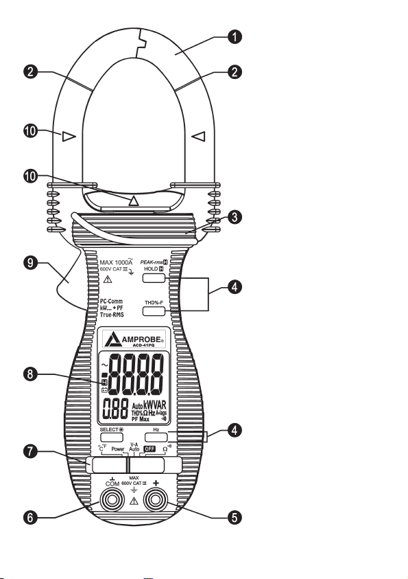
➊ Transformer Clamp Jaws
for AC current magnetic
field pick up
➋ Jaw marking lines for
ACA (& thus Power)
position error indication
➌ Hand /Finger Barrier to
indicate the limits of safe
access to the jaws during
current measurements
➍ Push-but tons for special
functions & features
➎ Input Jack for all
functions EXCEPT noninvasive ACA current (&
thus Power) function
➏ Common (Ground
reference) Input Jack
for all functions EXCEPT
non-invasive ACA current
(& thus Power) function
➐ Slide-switch Selector to
turn the power ON /OFF
and Select a function
➑ LCD display
➒ Jaw trigger for opening
the transformer clamp
jaws
➓ Jaw center Indicators,
at where best AC A (&
thus Power) accuracy is
specified
This user’s manual uses only
representative model(s) for
illustrations. Please refer
specification details for
function availabilit y to each
model.
3
Page 5

ACD-31P / ACD-41PQ
1000A Clamp-on Power Quality Meters
CONTENTS
Symbols .............................................................................................................................................5
Safety Information ...........................................................................................................................
Unpacking and Contents .................................................................................................................6
Introduction ......................................................................................................................................
Operation .........................................................................................................................................
Alignment marks (see Fig. 1) .....................................................................................................
PEAK-rms Hold
HOLD
THD%-F (Total Harmonic Distortion-Fundamental) (see figure 3) ..........................................
SELECT / Backlight (
Frequency (see figure 4) ............................................................................................................
Auto Power Off function ...........................................................................................................
RS232C PC computer interface capabilities ...............................................................................8
AutoVATM Measurement (see figures 5) ...................................................................................8
Resistance Measurement (See Fig. 6) ........................................................................................
Continuity Test (See Fig. 6) ........................................................................................................
Temperature Measurement (see figure 7) ................................................................................8
Power Measurement ..................................................................................................................9
Power Measurement - Single Phase (Ø) (see figure 8) ...........................................................9
Power Measurement – 3 Phase (Ø) - 3 Wire (see figure 9) .....................................................
Power Measurement - 3 Phase (Ø) - 4 Wire (see figure 10) ..................................................
Power Factor (PF) ....................................................................................................................
Maintenance and Repair ..............................................................................................................10
Battery Replacement (see Fig. 11) ..........................................................................................
Specifications .................................................................................................................................11
General .....................................................................................................................................
Electrical (23 °C ± 5 °C) < 75% RH ...........................................................................................
(see figure 2) ................................................................................................7
(Data Hold) ..................................................................................................................7
) .............................................................................................................7
5
6
6
6
7
7
7
8
8
9
9
10
11
11
12
4
Page 6

SYMBOLS
Battery
Double insulated
Direct Current
Alternating Current
Conforms to relevant Australian
standards.
Do not dispose of this product
as unsorted municipal waste.
Application around and
removal from hazardous live
conductors is permitted
SAFETY INFORMATION
The ACD-31P and ACD-41PQ Digital Clamp meters conform to EN61010-1:20 01;
•
EN61010- 2-032: 2002; CAT III 600 V, class 2 and pollution deg. 2
•
This instrument is EN61010-1 certified for Installation Category III (600V ). It is
recommended for use in distribution level and fixed installations, as well as lesser
installations, and not for primary supply lines, overhead lines and cable systems.
Do not exceed the maximum overload limit s per function (see specifications) nor the
•
limits marked on the instrument itself. Never apply more than 6 00 Vdc /600 V ac rms
between the test lead and earth ground.
Warnings and Precautions
Before and after hazardous voltage measurements, test the voltage function on a
•
known source such as line voltage to determine proper meter functioning.
Disconnect the tes t leads from the test points before changing meter functions.
•
Disconnected from the meter’s test leads before measuring current.
•
•
Inspect the Clampmeter, test leads and accessories before every use. Do not use any
damaged part.
•
Never ground yourself when taking measurements. Do not touch exposed circuit
elements or test probe tips.
Do not operate the instrument in an explosive atmosphere.
•
To reduce the risk of fire or elec tric shock, do not expose this product to rain or
•
moisture.
The meter is intended only for indoor use. To avoid electrical shock hazard, obser ve the
•
proper safet y precautions when working with voltages above 60 VDC or 30 VAC rms.
These voltage levels pose a potential shock hazard to the user.
Refer to the manual
Dangerous Voltage
Earth Ground
Audible tone
Complies with EU directives
Under writers Laboratories.
5
Page 7

Before and after hazardous voltage measurements, test the voltage function on a
•
known source such as line voltage to determine proper meter functioning.
Keep your hands /fingers behind the hand /finger barriers (of the meter and the test
•
leads ) that indicate the limits of safe access of the hand-held part during measurement.
•
Inspect test leads, connectors, and probes for damaged insulation or exposed metal
before using the instrument. If any defects are found, replace them immediately.
This Clamp-on meter is designed to apply around or remove from un-insulated
•
hazardous live conductors. Individual protective equipment must be used if hazardous
live par ts of the installation could be accessible.
•
Exercise extreme caution when: measuring voltage >20 V // current >10 mA // AC power
line with induc tive loads // AC power line during elec trical storms // current, when the
fuse blows in a circuit with open circuit voltage >1000 V // servicing CRT equipment.
Remove test leads before opening the case to change the battery.
•
Disconnect circuit power and discharge all high-voltage capacitors before testing
•
resistance, continuity, diodes, or capacitance.
To avoid false readings, which could lead to possible elec tric shock or personal injury,
•
replace the bat teries as soon as the low battery indicator () appears.
CAUTION
For non-invasive ACA current measurements, clamp the jaws around only one single
conductor of a circuit for load current measurement. More than 1 conductor will cause
false readings.
UNPACKING AND CONTENTS
Your shipping carton should include
1 ACD-31P or ACD-41PQ
1 Test lead set
1 Type K Thermocouple probe
2 AAA - 1.5V Bat teries
1 Users Manual
1 Carrying Case
If any of the items are damaged or missing, immediately return the complete package to
the place of purchase for an exchange.
INTRODUC TION
The ACD-31P and ACD-41PQ are True RMS responding, autoranging, 400 Amp / 600 V
Clamp-On power quality meters. The features include AC / DC voltage, AC / DC current,
Resistance, Continuity and Power Quality measurements.
OPER ATION
Alignment mark s (see Fig. 1)
Place conductor within the jaws at the intersection of the indicated mark s as close as
possible to maximize the accuracy of the reading.
6
Page 8

PEAK-rms Hold (see figure 2)
Peak-rms captures and displays the maximum RMS value of surge voltage or current with
durations as short as 65ms when in Vac or Aac.
Press and hold Peak-rms button for 2 beeps to enter this mode.
1.
2.
The LCD annuciators ‘P-‘ & ‘Max’ are turned on.
Press and hold Peak-rms button for 2 beeps to exit this mode.
3.
HOLD (Data Hold)
Freezes the reading present on the LCD at the moment the button is pressed.
Set up the meter for the type of measurement de sired.
1.
Connect the test leads or clamp jaws to the circuit/component to be measured.
2.
3.
Press Hold button.
4.
The LCD reading will freeze and display ‘
reading will not change until you press the Hold button again
Caution
Connection to a Hazardous Live circuit will still display the previous reading. This
function will not update the reading.
THD%-F (Total Harmonic Distortion- Fundamental) (see figure 3)
Fundamental distor tion is the percentage ratio of the Total Harmonics RMS value to the
Fundamental RMS value of a voltage or current signal.
THD% -F = (Total Harmonics RMS / Fundamental RMS) x 100%
An ideal sinusoidal waveform has a value of 0.00 THD%. A highly distor ted sinusoidal
waveform may have higher THD% value, up to several hundred.
Note: Used with Vac or Aac, THD%- F displays values up to 99 THD% in the secondar y mini
display. Press THD%-F button to move THD%-F readings to main display to show readings
up to 999.9 THD% . Pressing THD%-F but ton will alternate the reading location.
SELEC T / Backlight (
Press Backlight button more than 1 second, enable /disable Backlight.
Press the SELEC T / Backlight button to step through the manually selected V-A Auto
function options :
Auto
Frequency (see figure 4)
Displays the line frequency when in Vac or Aac. Trigger levels vary with the ranges.
1.
Press the ‘Hz’ button to display the signal frequency.
2.
Press the ‘Hz’ again to return to previous display.
Auto Power Off function
The clamp meter powers down automatically af ter approximately 17 minutes of inactivity.
To turn it back on, move the func tion selector switch to OFF and back to a measuring
function.
To disable Auto Power Off, press and hold the HOLD button while moving the slide switch
)
→ THD% Aac → THD% Vac → Vdc → Auto
‘. You may now remove the test leads and the
7
Page 9

to the desired function from OFF.
RS232C PC computer interface capabilities
The instrument is equipped with an optical isolated data output port at the back case
near the battery compartment. An optional PC interface kit RS232 KIT2 (Optical Adapter
Back, RS232 Cable and Amprobe Download Suite) is required to connect the meter to PC
computer thru R S232C protocol.
1.
To enable the RS-232 output, press-and-hold the Hz button while sliding the functionselec tor to a function.
2.
The LCD displays ’
To disable the RS-232 output, slide the function-selector to any other position.
3.
AutoVATM Measurement ( see figures 5)
Selec t the AutoVA position.
1.
2.
With no input, the meter displays “Auto” when it is ready.
3.
If no ACA current input via the jaws and a voltage signal > 2.4 Vdc or 30 Vac (40 Hz to
500 Hz) is present, the meter will display the voltage value with annunciator.
4.
If no voltage signal is present on ‘+” COM terminals and a ACA current signal > 1 AC A
(40 Hz to 500 Hz) is present, the meter will display the current value and ~ A.
The Auto-VA feature stays at the auto-select function as long as its signal remains
5.
above the specified threshold.
6.
Press the SELEC T but ton momentarily to manually step thru the functions (ACA
→ DCV → Auto-VA).
Resistance Measurement (See Fig. 6)
Selec t the ‘ Ω ‘ function .
1.
2.
Inser t the test leads into the jacks. The red lead into V/
jack.
Remove power from the circuit being tested and discharge all the capacitors.
3.
Connect the test leads to the circuit, the resistance measured will be displayed.
4.
5.
If OL appears on the highest range, the resis tance is too large to be measured.
Continuity Test ( See Fig. 6)
Selec t the ‘' function.
1.
2.
Inser t the test leads into the jacks, the red lead into V/
jack.
Remove power from the circuit being tested and discharge all the capacitors.
3.
Connect the test leads to the circuit,
4.
The resistance will be displayed and the buzzer sounds when the resistance value is
5.
between 10 and 300 Ω.
Temperature Measurement (see figure 7)
1.
Selec t the °C /°F position.
2.
Press SELECT button to toggle between °C and °F measurement functions.
3.
Inser t the banana-plug t ype -K temperature bead probe noting correct polarity.
‘ to confirm activation af ter the Hz button is released.
→ ACV
Ω jack, and black lead into COM
Ω jack, and black lead into COM
8
Page 10

Power Measurement
Polarity configuration note :
When measuring load circuits with power absorptions, positive (‘+’ implied) W or kW ( Real
Power) readings indicate correct measurement setups. Negative readings (“-“ segment on)
indicate either the clamp-on jaws direction or the test leads polarity is reversed in such
cases. Correct the setups to get correc t readings.
Power Measurement - Single Phase (Ø) (see figure 8)
Selec t the Power position.
1.
Press SELEC T button momentarily to select W ( real power), VAR (reactive power) or VA
2.
(apparent power) measurement functions.
3.
Connect COM input to neutral or GRD.
Connect ‘ + ‘ input to the phase being tested.
4.
Clamp jaws around the phase wire
5.
The display will show reading, W ( real power), VAR (reactive power) or VA (apparent
6.
power) measurement and PF.
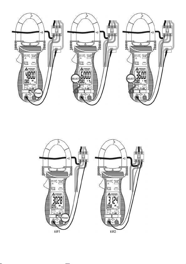
Power Measurement – 3 Phase (Ø) - 3 Wire (see figure 9)
Selec t the Power position.
1.
Press SELEC T button momentarily to select W ( real power) or VA (apparent power)
2.
measurement functions.
3.
Connect COM input to Ø 3 terminal .
Connect ‘ + ‘ input to Ø 1 terminal
4.
Clamp jaws around to Ø 1 wire
5.
The display will show reading, W ( real power) or VA (apparent power) measurement
6.
and PF.
7.
Write down the reading as kW1, kVA1
8.
Connect COM input to Ø 3 terminal .
Connect ‘ + ‘ input to Ø 2 terminal
9.
Clamp jaws around to Ø 2 wire
10.
The display will show reading, W ( real power) or VA (apparent power) measurement
11.
and PF.
12.
Write down the reading as kW2
Load Balanced Unbalanced
kW Total kW1 + kW2 kW1 + kW2
kVA Total 1.732 * kVA1 not applicable
kVAR Total √ kVA Total2 - kW Total
2
not applicable
Power Measurement - 3 Phase (Ø) - 4 Wire (see figure 10)
Selec t the Power position.
1.
Press SELEC T button momentarily to select W ( real power), VA (apparent power) or
2.
VAR (reactive power) measurement functions.
9
Page 11

Connect COM input to neutral or ground terminal.
3.
Connect ‘ + ‘ input to Ø 1 terminal
4.
Clamp jaws around to Ø 1 wire
5.
The display will show reading, W ( real power), VA (apparent power)or VAR (reactive
6.
power) measurement and PF.
7.
Write down the reading as kW1, kVA1, kVAR1
8.
Connect COM input to neutral or ground terminal.
Connect ‘ + ‘ input to Ø 2 terminal
9.
Clamp jaws around to Ø 2 wire
10.
The display will show reading, W ( real power), VA (apparent power) or VAR (reactive
11.
power) measurement and PF.
12.
Write down the reading as kW2, kVA2, kVAR2
13.
Connect COM input to neutral or ground terminal.
Connect ‘ + ‘ input to Ø 3 terminal
14.
Clamp jaws around to Ø 3 wire
15.
The display will show reading, W ( real power), VAR (reactive power) or VA (apparent
16.
power) measurement and PF.
17.
Write down the reading as kW3, kVA3, kVAR3
Load Balanced Unbalanced
kW Total 3 * kW1 kW1 + kW2 + kW3
kVA Total 3 * kVA1 kVA1 + kVA2 + kVA3
kVAR Total 3 * kVAR1 kVAR1 + kVAR2 + kVAR3
Power Factor (PF)
Total Power Factor =
“A-lags” annunciator indicates an inductive circuit , or Cur rent A lag s Voltage V (phase-
shift angle θ is “+”).
“A-lags” not visible indicates a c apacitive circuit, or Current A lead s Voltage V (phase-shift
angle θ is “-”).
MAINTENANCE AND REPAIR
If there appears to be a malfunc tion during the operation of the meter, the following
steps should be performed in order to isolate the cause of the problem:
Check the battery.
1.
Review the operating instructions for possible mistakes in operating procedure.
2.
3.
Inspect and test the test leads for a broken or intermittent connection.
Except for the replacement of the battery or test probes, repair of the multimeter
should be performed only by a Factor y Authorized Service Center or by other qualified
instrument service personnel. The front panel and case can be cleaned with a mild solution
of detergent and water. Apply sparingly with a sof t cloth and allow to dry completely
before using. Do not use aromatic hydrocarbons or chlorinated solvents for cleaning.
Real Power ( V rms * A rms * Cos θ ) /Ap parent Power (V rms * A rms)
10
Page 12

Battery Replacement (see Fig. 11)
Warning
To prevent electrical shock or meter damage, disconnect the meter’s tes t leads from any
circuit and the meter, then turn the meter off before removing the battery cover. Batter y
replacement should be performed in a clean environment and with appropriate care taken
to avoid contaminating the meter’s interior components.
Remove the screws and lif t the battery cover.
1.
2.
Replace the bat terie s with the same t ype (1.5V AA A). Note polarity guide below the
battery.
Replace the bat tery cover and screws.
3.
SPECIFIC ATIONS
General
Display :
Voltage functions : 6000 counts LCD display (s)
Power, Ohm & Hz functions : 9999 counts LCD display(s)
ACA clamp-on func tion : 4000 counts LCD display (s)
Update Rate :
Power function: 1 per second nominal
Voltage, ACA clamp- on, Ohm, Hz & Temperature functions : 4 per second nominal
Polarity : Automatic
Operating Temperature :
@ 40°C
Altitude : Indoor operation, below 2000m.
Storage Temperature : -20°C to 60°C, < 80% R .H. (with batter y removed)
Temperature Coef ficient :
-40°C)
Sensing : True RMS sensing
Power Supply : standard 1.5V AAA Size ( NE DA 24A or IE C LR03) bat tery X 2
Low Battery :
Power Consumption :
Voltage, ACA, Hz & Power functions : 10mA t ypical
Ohm & Temperature functions: 4mA typical
APO Timing : Idle for 17 minutes
APO Consumption :
Jaw opening & Conductor diameter : 45mm max
Dimension : 224 x 78mm x 40 mm (8.9 x 3.1 x 1.6 in.)
Weight : 224 gm approx
Safety LVD: Meets EN60101-1:20 01; EN61010-2-032 (2002), Category III- 600 Volts ac & dc;
pollution degree : 2
Below approx. 2.4V
0°C to 40 °C; < 80% RH @ < 31°C; decreasing linearly to 50% RH
nominal 0.15 x (specified accuracy)/ °C @ (0°C -18°C or 28°C
10µA typical
11
Page 13

EMC: EN 61326 -1 This product complies with requirements of the following
European Community Directives : 89 /336/ EEC (Electromagnetic Compatibility) and
73/23/EEC ( Low Voltage) as amended by 93 /68/EEC ( CE Marking). However, electrical
noise or intense elec tromagnetic fields in the vicinity of the equipment may disturb the
measurement circuit. Measuring instruments will also respond to unwanted signals that
may be present within the measurement circuit. Users should exercise care and take
appropriate precautions to avoid misleading results when making measurements in the
presence of electronic interference.
Electrical (23 °C ± 5 °C) < 75% RH
AC Voltage
Voltage Range Accuracy
50Hz to 60Hz
600.0V
CMRR : > 60 dB @ DC to 60 Hz, Rs = 1 k
Input Impedance: 2 M
Crest Factor: < 2.3 : 1 at full scale; < 4.6 : 1 at half scale
ACV AutoVATM Threshold : 30VAC (40 to 500 Hz) nominal
DC Voltage
Range : 600.0 V
Accuracy: ± (0.5% rdg + 5d)
NMRR : > 50 dB @ 50 /60 Hz
CMRR : >120 dB @ DC, 50/ 60 Hz, Rs = 1 k
Input Impedance: 2 M
DCV AutoVATM Threshold : 2.4VDC nominal
PEAK-rms HOLD (ACA & AC V only)
Response: 65ms to 9 0% rdg
Ohms
Range : 000.0 to 999.9
Accuracy: ± (1.0% rdg + 6d)
Open Circuit Voltage : 0.4VDC typical
Audible Continuity Tester
Audible threshold: between 10Ω and 300Ω.
Response time: 250µs
45 to 50Hz, 60 to 50 0Hz
500Hz to 3.1kHz
Ω, 30 pF nominal
Ω, 30 pF nominal
Ω
± (0.5% rdg + 5d)
± (1.5% rdg + 5d)
± (2.5% rdg + 5d)
Ω
Ω
ACA Current (Clamp-on)
12
Page 14
Range Frequency Accuracy
1) 2)
40.00A, 400.0A, 100 0A 50 Hz / 60 Hz ± (0.5% rdg + 5d)
40.00A, 400.0A
1000A ± (2.5% rdg + 5d)
40.00A, 400.0A
1000A ± (3.0% rdg + 5d)
45 to 50 Hz, 60 to 500 Hz
500 Hz to 3.1 kHz
± (2.0% rdg + 5d)
± (2.5% rdg + 5d)
ACA AutoVATM Threshold : 1A AC (40Hz ~ 500Hz only) nominal
Crest Factor:
40.00A & 400.0A: < 2.5 : 1 at full scale; < 5.0 : 1 at half scale
1000A : < 1.4 : 1 at full scale; < 2.8 : 1 at half scale
1)
Induced error from adjacent current- carrying conductor: < 0.06A /A
2)
Specified accuracy is from 1% rdg to 100% rdg of range and for measurements made at
the jaw center. When the conductor is not positioned at the jaw center, position errors
introduced are:
Add + 1% rdg to specified accuracy for measurements made WITHIN jaw marking lines
(away from jaw opening)
Add + 4% rdg to specified accuracy for measurements made BEYOND jaw marking lines
(toward jaws opening)
Temperature
Range Accuracy
-50°C to -20°C ± (2.0% rdg + 6°C)
-20°C to 300°C ± (2.0% rdg + 3°C )
-58°F to -4°F ± (2.0% rdg + 12°F)
-4°F to 572°F ± (2.0% rdg + 6°F)
Type-K thermocouple range & accurac y not included
Frequency
Range 5.00 Hz to 500.0 Hz
Accuracy: ± (0.5% rdg +4 d
Range Sensitivity (Sine RMS)
40A > 4A
400A > 40A
1000A > 400A
600V > 30V
THD% rdg-F
1)
(ACD-41PQ only)
13
Page 15

Range : 0.0% to 999.9%
Harmonic Accuracy
3)
2)
Fundamental ± (1.5% rdg + 6d)
2nd ~ 3rd ± (5.0% rdg + 6d)
4th ~ 16th ± (2.5% rdg + 6d)
17th ~ 46th ± (3.0% rdg + 6d)
47th ~ 51st ± (4.5% rdg + 6d)
1)
THD- F is defined as : (Total Harmonic RMS / Fundamental RMS) x 100%
2)
Range for Dual Display mode: 0 % to 99%
3)
Specified accuracy @ ACA fundamental > 5A ; ACV fundamental > 50V
Total Power Factor ( PF)
Range Accuracy
0.10 to 0.99
1)
Specified accuracy @ ACA fundamental > 2A ; AC V fundamental > 50V
1)
F to 21st harmonic
22nd to 51st harmonic
± 3d ± 5d
Power (VA)
Range Accuracy
1) 2)
0 to 600.0 kVA F to 10th 11th to 46th 47th to 51st
@ PF = 0.99 to 0.1
± (2.0% rdg + 6d) ± (3.5% rdg + 6d) ± (5.5% rdg + 6d)
Power (kW and kVAR )
Range Accuracy
0 to 600.0 kW
/ kVAR
@ PF = 0.99 to
0.70
@ PF = 0.70 to
0.50
@ PF = 0.50 to
0.30
@ PF = 0.30 to
0.20
1)
Specified accuracy is for ACA clamp measurement at the center of jaws. When the
conductor is not positioned at the jaw center, position error s introduced are: Add 1%
rdg to specified accuracy for AC A measurements made WITHIN jaw marking lines (away
1) 3)
F to 10th
± (2.0% rdg + 6d
± (3.0% rdg + 6d)
11th to 25th 26th to 46th 47th to 51st
± (3.5% rdg
+ 6d)
± (4.5% rdg
+ 6d)
± (10% rdg + 6d)
± (4.5% rdg + 6d)
± (10% rdg + 6d ) ± (15% rdg +6d)
14
Page 16

from jaw opening)
Accuracy is not specified for AC A measurement made BEYOND jaw marking lines (toward
jaws opening)
2)
Add 1% rdg to specified accuracy @ AC A fundamental < 5A or ACV fundamental < 90V.
Accuracy is not specified @ ACA fundamental < 1A or ACV fundamental < 30V
3)
Add 1% rdg to specified accuracy @ AC A fundamental < 5A or ACV fundamental < 90V.
Accuracy is not specified @ ACA fundamental < 2A or ACV fundamental < 50V
15
Page 17

Figure 1. Alignment Marks Figure 2. PEAK-rms
Figure 3. THD% -F
Figure 4. Frequency
16
Page 18
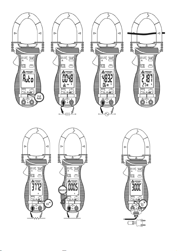
Figure 5. VDC VAC ACA
Resistance Continuity
Figure 6.
Figure 7. Temperature
17
Page 19
Φ1Φ2Φ3
N
Φ1Φ2Φ3
N
Φ1Φ2Φ3
N
kW kVA kVAR
Figure 8. Power
Φ1Φ2Φ3
Φ1Φ2Φ3
Figure 9. 3 Phase 3 Wire
18
Page 20

Φ1Φ2Φ3
N
Figure 10 3 Phase 4 Wire
Φ1Φ2Φ3
Φ1Φ2Φ3
N
N
Figure 11 Battery Replacement
19
Page 21

20
Page 22

ACD-31P
ACD-41PQ
Pinces multimètres 1000 A
Mode d’emploi
ACD-31P_Rev001
© 2008 Amprobe Test Tools.
Tous droits réservés.
21
Français
Page 23

Limites de garantie et de responsabilité
Amprobe garantit l’absence de vices de matériaux et de fabrication de ce produit
pendant une période d’un an prenant ef fet à la date d’achat. Cette garantie ne
s’applique pas aux fusibles, aux piles jetables ni à tout produit mal utilisé, modifié,
contaminé, négligé ou endommagé par accident ou soumis à des conditions anormales
d’utilisation et de manipulation. Les distributeurs agréés par Amprobe ne sont pas
autorisés à appliquer une garantie plus étendue au nom d’Amprobe. Pour bénéficier
de la garantie, renvoyez le produit accompagné d’un justificatif d’achat auprès d’un
centre de services agréé par Amprobe Test Tools ou d’un dis tributeur ou d’un revendeur
Amprobe. Voir la section Réparation pour tous les détails. LA PRESENTE GARANTIE EST
LE SEUL ET EXCLUSIF RECOURS. TOUTES AUTRES GARANTIES, EXPLICITES, IMPLICITES OU
STATUTAIRES, NOTAMMENT LE CAS ECHEANT LES GARANTIES DE QUALITE MARCHANDE
OU D’ADAPTATION A UN OBJECTIF PARTICULIER SONT EXCLUES PAR LES PRESENTES. LE
FABRIC ANT NE SERA EN AUCUN CAS TENU RESPONSABLE DES DOMMAGES PARTICULIERS,
INDIRECTS, ACCIDENTELS OU CONSECUTIFS, NI D’AUCUNS DEGATS OU PERTES DE
DONNEES, SUR UNE BASE CONTR ACTUELLE, EXTRA-CONTRAC TUELLE OU AUTRE. Etant
donné que certaines juridictions n’admettent pas les limitations d’une condition de
garantie implicite, ou l’exclusion ou la limitation de dégâts accidentels ou consécutifs , il se
peut que les limitations et les exclusions de cette garantie ne s’appliquent pas à votre cas.
Réparation
Tous les outils de test renvoyés pour un étalonnage ou une réparation couverte ou non par
la garantie doivent être accompagnés des éléments suivants: nom, raison sociale, adresse,
numéro de téléphone et justificatif d’achat. Ajoutez également une brève description
du problème ou du service demandé et incluez les cordons de mesure avec l’appareil. Les
frais de remplacement ou de réparation hors garantie doivent être acquittés par chèque,
mandat , carte de crédit avec date d’expiration, ou par bon de commande payable à l’ordre
d’Amprobe® Test Tools.
Remplacements et réparations sous garantie – Tous pays
Veuillez lire la déclaration de garantie et vérifier la pile avant de demander une
réparation. Pendant la période de garantie, tout outil de test défectueux peut être
renvoyé auprès de votre distributeur Amprobe® Test Tools pour être échangé contre
un produit identique ou similaire. Consultez la section «Where to Buy» sur le site
www.amprobe.com pour obtenir la liste des distributeurs dans votre région. Au Canada
et aux Etats-Unis, les appareils devant être remplacés ou réparés sou s garantie peuvent
également être envoyés dans un centre de services Amprobe® Test Tools (voir les adresses
ci-dessous).
Remplacements et réparations hors garantie – Canada et Etats-Unis
Les appareils à réparer hors garantie au Canada et aux Etats-Unis doivent être envoyés
dans un centre de service Amprobe® Test Tools. Appelez Amprobe® Test Tools ou
renseignez-vous auprès de votre lieu d’achat pour connaître les tarifs en vigueur de
remplacement ou de réparation.
Aux Etats-Unis Au Canada
Amprobe Test Tools Amprobe Test Tools
Everet t, WA 98203 Mississauga, Ontario L4Z 1X9
Tél.: 877-AMPROBE (267-7623) Tél.: 905-890-7600
Remplacements et réparations hors garantie – Europe
Les appareils européens non couverts par la garantie peuvent être remplacés par votre
distributeur Amprobe® Test Tools pour une somme nominale. Consultez la section
«Where to Buy» sur le site www.amprobe.com pour obtenir la liste des distributeurs
dans votre région.
Adresse postale européenne*
Amprobe® Test Tools Europe
In den Engematten 14
79286 Glottertal, Allemagne
Tél.: +49 ( 0) 7684 8009 - 0
*(Réservé à la correspondance – Aucune réparation ou remplacement n’est possible à cette
adresse. Nos clients européens doivent contacter leur distributeur.)
22
Page 24

➊ Mâchoires de pince
transformateur pour
capter le champ
magnétique du courant
alternatif (c .a. )
➋ Repères des mâchoires
pour indiquer l’erreur
de position A c.a. (donc
depuissance)
➌ Collerette de protection
des doigts indiquant les
limites de sécurité sur les
mâchoires pendant les
mesures de courant
➍ Boutons-poussoirs pour
les fonctionnalités
spéciales
➎ Jack d’entrée pour toutes
les fonctions SAUF la
fonction de courant
Ac.a. (donc de puissance)
non invasive
➏ Jack d’entrée au commun
(référence à la terre)
pour toutes les fonctions
SAUF la fonction de
mesure du courant Ac.a.
(donc de puissance)
noninvasive
➐ Commutateur à glissière
marche /arrêt et sélecteur
de fonc tion
➑ Ecran LCD
➒ Gâchette d’ouverture
des mâchoires de la pince
transformateur
➓ Indicateurs du centrage
des mâchoires, à l’endroit
où la meilleure précision
A c.a. est spécifiée
Ce mode d’emploi ne
représente les modèles qu’à
titre indicatif. Repor tezvous aux détails des
caractéris tiques pour la
disponibilité des fonctions sur
chaque modèle.
23
Page 25

ACD-31P / ACD-41PQ
Pinces multimètres 1000 A
TABLE DES MATIERES .....................................................................................................................24
Symboles .........................................................................................................................................25
Consignes de sécurité .....................................................................................................................25
Déballage et vérification du contenu ...........................................................................................26
Introduction ....................................................................................................................................
Fonctionnement .............................................................................................................................
Repères d’alignement (voir Fig. 1) ...........................................................................................
PEAK-rms Hold
HOLD
THD%-F (Taux de distorsion harmonique par rapport au fondamental) (voir Figure 3) .....
SELECT / Rétroéclairage (
Fréquence (voir Figure 4) .........................................................................................................
Fonction d’arrêt automatique .................................................................................................
Capacités de l’interface informatique PC RS232C ...................................................................28
Mesure Auto-VA (voir Figure 5) ...............................................................................................
Mesure de résistance (voir Fig. 6) ............................................................................................
Contrôle de continuité (voir Fig. 6) .........................................................................................
Mesure de température (voir Figure 7) ...................................................................................
Mesure de puissance .................................................................................................................29
Mesure de puissance en monophasé (Ø) (voir Figure 8) ......................................................
Mesure de puissance en triphasé (Ø) – 3 fils (voir Figure 9) .................................................
Mesure de puissance en triphasé (Ø) – 4 fils (voir Figure 10) ...............................................
Facteur de puissance (PF) ........................................................................................................
Entretien et R
Changement des piles (voir fig. 11) ........................................................................................31
Caractéristiques générales ............................................................................................................31
Caractéristiques générales ......................................................................................................31
Electricité (23 °C ± 5 °C) < 75% HR .........................................................................................
(voir Figure 2) .............................................................................................27
(Maintien de l’affichage) ...........................................................................................27
) .....................................................................................................27
eparation ................................................................................................................30
26
26
26
27
27
27
28
28
28
28
29
29
29
30
32
24
Page 26

SYMBO LES
Batterie
Double isolation
Courant continu
Courant alternatif
Conformes aux normes
australiennes per tinentes
Ne pas mettre ce produit
au rebut parmi les
déchetsménagers
L’application et le retrait
de la pince à proximité de
conducteur s sous tension
dangereuse sont autorisés
CONSIGNES DE SÉCURITÉ
Les pinces multimètres numériques modèles ACD-31P et ACD-41PQ sont compatibles avec
•
EN61010-1:2001; EN610102-032:2002; CAT III 600 V, classe 2 et degré de pollution2.
Cet appareil est certifié conforme à la norme EN61010-1 pour les installations de
•
catégorie III (600 V). Il est recommandé pour les installations fixes et les équipements
au niveau distribution, ainsi que pour les installations de catégories inférieures, mais il
n’est pas destiné aux lignes du réseau d’alimentation électrique principale, aux lignes
aériennes ou aux systèmes câblés.
Ne pas dépasser les limites de surcharge maximum par fonction (voir les caractéristiques
•
techniques) ou les limites indiquées sur l’appareil lui-même. Ne jamais appliquer plus de
600 V c.c./600 V c.a. eff. entre le cordon de mesure et la prise de terre.
Mises en garde et précautions
Avant et après les mesures de tensions dangereuses, tester la fonction de tension sur
•
une source connue, une tension secteur p. ex ., pour déterminer le bon fonctionnement
du multimètre.
Débrancher les cordons de me sure des points de test avant de changer de fonction sur
•
le multimètre.
Débrancher les cordons de me sure du multimètre avant de mesurer le courant.
•
Inspecter la pince multimètre, les cordons de mesure et les accessoires avant toute
•
utilisation. Ne pas utiliser de pièce endommagée.
Ne jamais se relier à la terre en prenant des mesures. Ne toucher ni aux éléments de
•
circuit exposés ni aux pointes des sondes de test .
Ne pas utiliser l’appareil dans une atmosphère explosive.
•
Pour réduire le risque d’incendie ou d’électrocution, ne pas exposer cet appareil à
•
l’humidité ou à la pluie.
Le multimètre est destiné à être utilisé à l’intérieur uniquement . Pour éviter les chocs
•
électriques, observer les précautions de sécurité appropriées en intervenant sur des
Se reporter au mode d’emploi
Tension dangereuse
Prise de terre
Signal sonore
Conforme aux directives
del’UE
Under writers Laboratories
25
Page 27

tensions supérieures à 60 V c.c. ou à 30 V c.a. eff. Ces niveaux de tension présentent un
risque d’élec trocution pour l’utilisateur.
Avant et après les mesures de tensions dangereuses, tester la fonction de tension sur
•
une source connue, une tension secteur p. ex ., pour déterminer le bon fonctionnement
du multimètre.
Garder les mains/ doigts derrière les collerettes de protection qui indiquent les limites
•
de sécurité du multimètre et des cordons pendant la mesure.
Inspecter les cordons de mesure, les connecteurs et les sondes pour détecter
•
l’endommagement de l’isolant ou les parties métalliques exposées avant d’utiliser
l’instrument. Remplacer immédiatement l’élément si des défauts sont détectés.
Cette pince multimètre est destinée à être retirée ou appliquée aux conducteurs sous
•
tension dangereuse non isolés. Utiliser des équipements de protection individuelle si
des pièces sous tension dangereuse risquent d’être accessibles.
Faire preuve d’extrême prudence en: mesurant une tension > 20 V / / un courant
•
> 10 mA // les ligne s d’alimentation sec teur avec charges inductives // les lignes
d’alimentation secteur pendant les orages électriques // un courant alors que le
fusible a sauté dans un circuit avec une tension en circuit ouver t > 1000 V // lors d’une
intervention sur un appareil à écran cathodique.
Retirer les cordons de mesure avant d’ouvrir le boîtier pour changer les pile s.
•
Débrancher l’alimentation du circuit et décharger tous les condensateurs à tension
•
élevée avant de contrôler la résistance, la continuité, les diodes ou la capacité.
Pour éviter les mesures erronées qui posent des risques d’électrocution ou de blessure,
•
remplacer les piles dès que l’indicateur d’état de piles faibles apparaît ().
ATTENTION
Pour les mesures de courant A c.a. non invasives, serrer les mâchoires autour d’un
conducteur du circuit pour mesurer le courant de charge. La prise en compte simultanée
de plusieurs conducteurs entraîne des mesures erronées.
DÉBALLAGE ET VÉRIFICATION DU CONTENU
Le carton d’emballage doit inclure les éléments suivants:
1 ACD-31P ou ACD-41PQ
1 Jeu de cordons de mesure
1 Sonde thermocouple de type K
2 Piles A AA – 1,5 V
1 Mode d’emploi
1 Mallet te de transport
Si l’un de ces éléments est endommagé ou manquant, renvoyez immédiatement le
contenu complet de l’emballage au lieu d’achat pour l’échanger.
INTRODUC TION
Les modèles ACD-31P et ACD-41PQ sont des pinces multimètres de 400 A / 600 V, avec
mode de gamme automatique et réponse eff. vraie. Ils proposent les fonctions de
mesure suivantes: tension c.a. / c.c., courant c.a. / c.c., résistance, continuité et qualité du
réseauélectrique.
FONC TIONNEMENT
Repères d’alignement (voir Fig. 1)
Positionnez le conducteur entre les mâchoires au niveau de l’inter section indiquée par les
repères, le plus près possible pour optimiser la précision de la lecture.
26
Page 28

PEAK-rms Hold (voir Figure 2)
La fonc tion Peak-rms capture et affiche la valeur ef ficace maximum de sur tension ou de
surintensité à des durées aussi brèves que 65 ms en mode V c.a. ou A c.a.
Maintenez le bouton Peak-rms enfoncé pendant 2 bips sonores pour ac tiver ce mode.
1.
Les indicateurs «P-» et «Max» sont activés.
2.
Maintenez le bouton Peak-rms enfoncé pendant 2 bips sonores pour quitter ce mode.
3.
HOLD (Maintien de l’affichage)
Gèle la mesure af fichée sur l’écran LCD lorsque cette touche est ac tivée.
Configurez le type de mesure souhaité pour le multimètre.
1.
Raccordez les cordons de mesure ou les mâchoires de la pince au circuit /composant
2.
àmesurer.
Appuyez sur le bouton Hold.
3.
La mesure est figée sur l’écran LCD et ‘‘ est affiché. Vous pouvez maintenant retirer
4.
les cordons; la mesure reste affichée tant que la touche Hold n’est pas réactivée.
Attention
Un branchement à un circuit sous tension dangereuse affiche toujours le relevé
précédent. Cette fonction n’actualise pas la mesure.
THD%-F (Taux de distorsion harmonique par rappor t au fondamental) (voir Figure 3)
La distorsion du fondamental est le rapport en pourcentage entre la valeur ef ficace des
harmoniques et la valeur efficace du fondamental d’un signal de courant ou de tension.
THD%- F = (Valeur efficace des harmoniques / valeur efficace du fondamental) x 100%
Ce signal de forme sinusoïdale idéale a une valeur de 0,00 THD%. Une forme d’onde
sinusoïdale très déformée peut présenter une valeur THD% plus élevée, jusqu’à
plusieurscentaines.
Remarque: Utilisé avec V c .a ou A c.a, THD%- F affiche les résultats jusqu’à 99 THD%
dans l’af fichage miniature secondaire. Appuyez sur THD% -F pour amener les mesures
THD% -F dans l’affichage principal et afficher les résultats jusqu’à 999,9 THD%. Appuyez
sur le bouton THD%- F pour basculer entre les deux affichages.
SELEC T / Rétroéclairage ()
Appuyez sur le bouton de rétroéclairage plus d’une seconde pour l’activer ou le désactiver.
Appuyez sur le bouton SELECT / rétroéclairage pour faire défiler les options de la fonction
V-A Auto sélectionnée manuellement:
Auto
Fréquence (voir Figure 4)
Affiche la fréquence secteur en mode V c.a. ou A c.a. Les niveaux de déclenchement
varient selon les gammes.
1.
2.
Fonction d’arrêt automatique
La pince multimètre s’éteint automatiquement après environ 17 minutes d’inac tivité.
Pour la remettre en marche, éloignez le sélec teur de fonction de la position OFF pour
choisir une fonction de mesure.
→ THD% A c.a. → THD% V c.a. → V c.c. → Auto
Appuyez sur le bouton «Hz» pour afficher la fréquence du signal.
Appuyez de nouveau sur «Hz» pour revenir à l’af fichage précédent .
27
Page 29

Pour désactiver l’arrêt automatique, maintenez le bouton HOLD enfoncé tout en éloignant
le commutateur de la position OFF vers la fonc tion souhaitée.
Capacités de l’interface informatique PC RS232C
L’instrument est équipé d’un por t de sortie de données à isolation optique au niveau du
boîtier dorsal près du compartiment des piles. Un kit d’inter face PC RS232 KIT2 disponible
option (capot d’adaptateur optique, cordon RS232 et Download Suite d’Amprobe) est
nécessaire pour brancher le multimètre au PC en utilisant le protocole RS232C.
Pour activer la sortie RS-232, maintenez le bouton Hz enfoncé en faisant glisser le
1.
sélec teur sur la fonction voulue.
L’écran LCD affiche ’ ‘ pour confirmer l’activation de la fonction après le relâchement
2.
du bouton Hz.
Pour désactiver la sortie RS-232, faites glisser le sélecteur de fonction sur une
3.
autreposition.
Mesure Auto-VA (voir Figure 5)
Sélec tionnez la position Auto-VA.
1.
En l’absence d’entrée, le multimètre affiche «Auto» lorsqu’il est prêt.
2.
En l’absence d’une entrée de courant A c.a. détectée par les mâchoires et d’un signal de
3.
tension > 2,4 V c.c. ou 30 V c.a. ( 40 Hz à 500 Hz) , le multimètre affiche la tension avec
un indicateur.
Si aucun signal de tension n’est présent aux bornes «+» COM alors qu’un signal de
4.
courant A c.a. > 1 A c.a. (40 Hz à 500 Hz) est présent, le multimètre af fiche l’intensité
et ~ A.
La fonc tion Auto-VA reste en mode de fonction automatique tant que son signal res te
5.
au-delà du seuil spécifié.
Appuyez temporairement sur le bouton SELEC T pour faire défiler les fonctions (ACA →
6.
ACV → DCV → Auto-VA).
Mesure de résistance (voir Fig. 6)
Sélec tionnez la fonction « Ω».
1.
Insérez les cordons de mesure dans les jacks. Le cordon rouge dans le jack V/Ω et le
2.
cordon noir dans le jack COM. Met tez le circuit testé hors tension et déchargez tous
lescondensateurs.
Reliez les cordons de mesure au circuit: la résistance mesurée s’affiche.
3.
Si OL apparaît sur la gamme la plus élevée, la résistance est trop forte pour
4.
êtremesurée.
Contrôle de continuité (voir Fig. 6)
Sélec tionnez la fonction ‘‘.
1.
Insérez les cordons de mesure dans les jacks, le cordon rouge dans le jack V/Ω et le
2.
cordon noir dans le jack COM.
Mettez le circuit testé hors tension et déchargez tous les condensateurs.
3.
Branchez les cordons de mesure au circuit.
4.
La résistance s’affiche et l’avertisseur indique que la résistance est comprise entre
5.
10et300 Ω.
Mesure de température (voir Figure 7)
1.
Sélec tionnez la position °C/ °F.
2.
Appuyez sur le bouton SELECT pour basculer entre les fonc tions de mesure °C et °F.
3.
Insérez la sonde à perle de type K à fiche banane en respectant la polarité.
28
Page 30

Mesure de puissance
Note sur la configuration de la polarité:
En mesurant des circuit s de charge avec des absorptions de puissance, le s mesures positive s
(«+» implicite) W ou kW (puissance réelle) indiquent des configurations de mesure
correc tes. Les mesures négatives (segment «-» affiché) indiquent que la direction des
mâchoires ou la polarité des cordons de mesure est inversée selon le cas. Corrigez les
configurations pour obtenir des mesures correctes.
Mesure de puissance en monophasé (Ø ) (voir Figure 8 )
Sélec tionnez la position Power.
1.
Appuyez temporairement sur le bouton SELECT pour sélectionner les fonctions de
2.
mesure W (puissance réelle), VAR (puissance réactive) ou VA (puissance apparente).
3.
Branchez l’entrée COM au neutre ou à GRD.
Branchez l’entrée «+» à la phase testée.
4.
Serrez les mâchoires autour du fil de phase.
5.
L’écran affiche maintenant la mesure W ( puissance réelle), VAR (puissance réactive) ou
6.
VA (puissance apparente) et PF.
Mesure de puissance en triphasé (Ø) – 3 fils (voir Figure 9)
Sélec tionnez la position Power.
1.
Appuyez temporairement sur SELEC T pour sélec tionner les fonctions de mesure
2.
W(puissance réelle) ou VA (puissance apparente).
Reliez l’entrée COM à la borne Ø 3.
3.
Reliez l’entrée «+» à la borne Ø 1.
4.
Serrez les mâchoires autour d’un fil Ø 1.
5.
L’écran affiche maintenant la mesure W ( puissance réelle) ou VA (puissance apparente)
6.
et PF.
Notez la valeur relevée sous la forme kW1, kVA1.
7.
Reliez l’entrée COM à la borne Ø 3.
8.
Reliez l’entrée «+» à la borne Ø 2.
9.
Serrez les mâchoires d ’un fil Ø 2.
10.
L’écran affiche maintenant la mesure W ( puissance réelle) ou VA (puissance apparente)
11.
et PF.
Notez la valeur relevée sous la forme kW2.
12.
Charge Equilibrée Déséquilibrée
kW total kW1 + kW2 kW1 + kW2
kVA total 1,732 * kVA1 non applicable
kVAR total √ kVA total2 - kW total
2
non applicable
Mesure de puissance en triphasé (Ø) – 4 fils (voir Figure 10)
Sélec tionnez la position Power.
1.
Appuyez temporairement sur le bouton SELECT pour sélectionner les fonctions de
2.
mesure W (puissance réelle), VA (puissance apparente) et VAR (puissance réac tive).
3.
Branchez l’entrée COM au neutre ou à la borne de terre.
29
Page 31

Reliez l’entrée «+» à la borne Ø 1.
4.
Serrez les mâchoires autour d’un fil Ø 1.
5.
L’écran affiche maintenant la mesure W ( puissance réelle), VA (puissance apparente) ou
6.
VAR (puissance réac tive) et PF.
7.
Notez la valeur relevée sous la forme kW1, kVA1, kVAR1.
8.
Reliez l’entrée COM au neutre ou à la borne de terre.
Reliez l’entrée «+» à la borne Ø 2.
9.
Serrez les mâchoires autour d’un fil Ø 2.
10.
L’écran affiche maintenant la mesure W ( puissance réelle), VA (puissance apparente) ou
11.
VAR (puissance réac tive) et PF.
12.
Notez la valeur relevée sous la forme kW2, kVA2, kVAR2.
13.
Reliez l’entrée COM au neutre ou à la borne de terre.
Reliez l’entrée «+» à la borne Ø 3.
14.
Serrez les mâchoires autour d’un fil Ø 3.
15.
L’écran affiche maintenant la mesure W ( puissance réelle), VAR (puissance réactive) ou
16.
VA (puissance apparente) et PF.
17.
Notez la valeur relevée sous la forme kW3, kVA3, kVAR3.
Charge Equilibrée Déséquilibrée
kW total 3 * kW1 kW1 + kW2 + kW3
kVA total 3 * kVA1 kVA1 + kVA2 + kVA3
kVAR total 3 * kVAR1 kVAR1 + kVAR2 + kVAR3
Facteur de puissance ( PF)
Facteur de puissance total =
(V eff. * A eff.)
L’indicateur «A-lags» indique un circuit inductif ou le ret ard du courant A p ar rapp ort à la
tension V (l’angle de déphasage θ est «+»).
Le circuit est c apacitif si l’indicateur «A- lags» n’est pas visible, ou le retard du courant A
par rapport à la tension V (l’angle de déphasage θ est «-»).
ENTRETIEN ET REPARATION
En cas de dysfonctionnement pendant le fonctionnement du multimètre, procédez comme
suit pour isoler la cause du problème:
Vérifiez le s piles.
1.
Consultez les consignes d’utilisation pour vérifier les erreurs possibles lors
2.
del’utilisation.
Inspectez et testez les cordons de mesure pour détecter un branchement intermit tent
3.
ou brisé.
A l’exception du changement des piles ou des sondes de test, les interventions sur le
multimètre doivent être effectuées en usine dans un centre de service agréé ou par un
autre personnel de réparation qualifié. La face avant et le boîtier peuvent être nettoyés
à l’aide d’une solution légère à base d’eau et de détergent. Appliquez cette solution avec
modération en utilisant un tissu doux et laissez bien sécher avant l’utilisation. N’utilisez
pas de solvants à base de chlore ou d’hydrocarbures aromatiques pour le nettoyage.
Puiss ance réelle (V eff.* A eff. * Cos θ )/Puissance apparente
30
Page 32

Changement des piles (voir fig. 11)
Avertissement
Pour éviter les chocs électriques ou l’endommagement du multimètre, débrancher les
cordons de mesure du circuit et du multimètre et mettre l’appareil hors tension avant
de retirer le capot du boî tier. Les piles doivent être remplacées dans un environnement
propre et avec soin pour ne pas contaminer les composants internes du multimètre.
Retirez les vis et soulevez le couvercle du compar timent des piles.
1.
Installez des piles neuves du même t ype (1,5 V A AA). Notez le repère de polarité
2.
sous la pile.
Replacez le couvercle du compar timent des piles et vissez.
3.
CAR ACTÉRISTIQUES GÉNÉRALES
Caractéristiques générales
Affichage:
Fonctions de tension: Ecran (s ) LCD 60 00 comptes
Fonctions de puissance, résis tance et fréquence: Ecran(s) LCD 9999 comptes
Fonction de pince A c.a.: Ecran (s) LCD 4000 comptes
Vitesse de rafraîchissement:
Fonction de puissance: 1 par seconde (nominale )
Fonctions de tension, pince A c.a., résistance, fréquence et température:
4 par seconde (nominale)
Polarité: Automatique
Température de fonctionnement: 0 °C à 40 °C; < 80% HR à < 31 °C; diminuant
linéairement jusqu’à 50% HR à 40 °C
Altitude: Fonctionnement en intérieur, en dessous de 2000 m
Température d’entreposage: -20 °C à 60 °C, < 8 0% H.R. (sans les piles)
Coefficient thermique: nominale 0,15 x (précision spécifiée)/ °C à ( 0 °C à 18 °C ou
28°C à40 °C )
Détection: Détection de mesure eff. vraie
Alimentation: 2 piles A AA standard de 1,5 V (NEDA 24A ou CEI LR03 )
Batterie faible:
Consommation d’énergie:
Fonctions de tension, A c.a., fréquence et puissance: 10 mA typique
Fonctions de température et de résistance: 4 mA typique
Arrêt automatique (APO):
Consommation avec APO: 10 µA typique
Ouverture des mâchoires et diamètre du conducteur:
Dimensions : 224 mm x 78 mm x 40 mm (8,9 x 3,1 x 1,6 po)
Poids: 224 gm environ
Sécurité LVD: Conforme à EN60101-1:2001 ; EN61010-2- 032(2002), catégorie III - 600 V c.a.
et c.c.; degré de pollution: 2
en dessous de 2,4 V environ
inactivité pendant 17 minutes
45 mm max
31
Page 33

CEM: EN 61326-1. Ce produit es t conforme aux exigences des direc tives suivantes de
la Communauté européenne: 89/336/CEE (Compatibilité électromagnétique) et 73/23 /CEE
(Basse tension) modifiée par 93 /68/CEE ( Marquage CE ). Toutefois, le bruit électrique ou
les champs électromagnétiques intenses à proximité de l’équipement sont susceptibles de
perturber le circuit de mesure. Les appareils de mesure réagissent également aux signaux
indésirables parfois présents dans le circuit de mesure. Les utilisateurs doivent faire preuve
de prudence et prendre les mesures nécessaires pour éviter les erreurs de mesure en
présence de parasites électromagnétiques.
Electricité (23 °C ± 5 °C ) < 75% HR
Tension alternative
Tension Gamme Précision
50 Hz à 60 Hz
600,0 V
Taux d’élimination en
mode commun: > 60 dB à c.c. de 60 Hz, Rs = 1 kΩ
Impédance d’entrée: 2 M
Facteur de crête: < 2,3 : 1 à pleine échelle; < 4,6 : 1 à demi-échelle
Seuil Auto-VA ACV: 30 V c.a. (40 à 500 Hz) nominal
Tension continue
Gamme: 600,0 V
Précision: ± (0,5% de lecture + 5c)
Taux d’élimination en
mode normal: > 50 dB à 50 /60 Hz
Taux d’élimination en
mode commun: > 120 dB à c.c. 50/60 Hz, Rs = 1 kΩ
Impédance d’entrée: 2 M
Seuil Auto-VA DCV: 2,4 V c.c. nominal
PEAK-rms HOLD (ACA et ACV uniquement)
Réponse: 65 ms à 90% de lec ture
Résistance
Gamme : 000,0 à 999,9 Ω
Précision: ± (1,0% de lecture + 6c)
Tension en circuit ouvert: 0,4 V c.c. typique
Avertisseur du test de continuité
Seuil sonore: entre 10 Ω et 30 0 Ω
Temps de réponse: 250 µs
45 à 50 Hz, 60 à 500 Hz
500 Hz à 3,1 kHz
Ω, 30 pF nominal
Ω, 30 pF nominal
± (0,5% de lecture + 5c)
± (1,5% de lecture + 5c)
± (2,5% de lecture + 5c)
32
Page 34

Courant A c .a. ( pince)
Gamme Fréquence Précision
1) 2)
40,00 A, 400,0 A, 1000 A 50 Hz/60 Hz ± (0,5% de lecture + 5c)
40,00 A, 400,0 A
1000 A ± (2,5% de lecture + 5c)
40,00 A, 400,0 A
1000 A ± (3,0% de lecture + 5c)
45 à 50 Hz, 60 à 500 Hz
500 Hz à 3,1 kHz
± (2,0% de lecture + 5c)
± (2,5% de lecture + 5c)
Seuil Auto-VA ACA: 1A c.a. (40 Hz à 50 0 Hz uniquement) nominal
Facteur de crête:
40,00 A et 400,0 A: < 2,5 : 1 à pleine échelle; < 5,0 : 1 à demi-échelle
1000 A: < 1,4 : 1 à pleine échelle; < 2,8 : 1 à demi-échelle
1)
Erreur induite du conducteur transportant le courant adjacent: < 0,06 A /A
2)
La précision est spécifiée entre 1% de la lecture et 100 % de la lecture de la gamme
et pour les mesures relevées au centre des mâchoires. Des erreurs de position sont
introduites lorsque le conducteur n’est pas positionné au centre des mâchoire s:
Ajouter + 1% de la lecture à la précision spécifiée pour les mesures relevées ENTRE les
repères des mâchoires (loin de l’ouverture des mâchoires).
Ajouter + 4% de la lecture à la précision spécifiée pour les mesures relevées AU-DELÀ des
repères des mâchoires (vers l’ouverture des mâchoires).
Température
Gamme Précision
-50 °C à -20 °C ± (2,0% de lecture + 6 °C)
-20 °C à 300 °C ± (2,0% de lecture + 3 °C)
-58 °F à - 4 °F ± (2,0% de lecture + 12 °F)
-4 °F à 572 °F ± (2,0% de lec ture + 6 °F)
Précision et gamme du thermocouple de type K non comprises
Fréquence
Gamme: 5,00 Hz à 500,0 Hz
Précision: ± (0,5% de lecture + 4c)
Gamme Sensibilité (sinusoïde, eff.)
40 A > 4A
400 A > 40A
1000 A > 400A
600 V > 30V
33
Page 35

THD% rdg-F 1) (ACD-41PQ uniquement)
Gamme: 0,0% à 999,9%
Harmonique Précision
3)
2)
Fondamental ± (1,5% de lec ture + 6c)
2e à 3e ± (5,0% de lecture + 6c)
4e à 16e ± (2,5% de lec ture + 6c)
17e à 46e ± (3,0% de lec ture + 6c)
47e à 51e ± (4,5% de lecture + 6c)
1)
THD- F est défini sous la forme: (Valeur efficace des harmoniques / valeur efficace du
fondamental) x 100%
2)
Gamme en double affichage: 0% à 99%
3)
Précision spécifiée au fondamental A c.a. > 5 A ; fondamental V c.a. > 50 V
Facteur de puissance total (PF)
Gamme Précision
0,10 à 0,99
1)
Précision spécifiée au fondamental A c.a. > 2 A ; fondamental V c.a. > 50 V
1)
F au 21e harmonique
22e au 51e harmonique
± 3c ± 5c
Puissance (VA)
Gamme Précision
1) 2)
0 à 600,0 kVA F au 10e 11e au 46e 47e au 51e
PF = 0,99 à 0,1
± (2,0% de lecture
+ 6c)
± (3,5% de lecture
+ 6c)
± (5,5% de lecture
+ 6c)
Puissance (kW et kVAR)
Gamme Précision
1) 3)
0 à 600,0 kW/kVAR F au 10e 11e au 25e 26e au 46e 47e au 51e
PF = 0,99 à 0,70
PF = 0,70 à 0,50
PF = 0,50 à 0,30
PF = 0,30 à 0,20
1)
La précision est spécifiée pour une mesure de pince A c.a. relevée au centre des
mâchoires. Des erreurs de position sont introduites lorsque le conducteur n’est pas
positionné au centre des mâchoires: Ajouter 1% de la lec ture à la précision spécifiée
± (2,0% de
lecture + 6c)
± (3,0% de
lecture + 6c)
± (3,5% de
lecture + 6c)
± (4,5% de lecture + 6c)
± (10% de lecture + 6c)
± (4,5% de
lecture + 6c)
± (10% de
lecture + 6c)
± (15% de
lecture + 6c)
34
Page 36

pour les mesures A c.a. relevées ENTRE les repères des mâchoires (loin de l’ouverture
desmâchoires).
La précision n’est pas spécifiée pour la mesure A c.a. relevée AU-DELÀ des repères des
mâchoires (vers l’ouverture des mâchoires) .
2)
Ajouter 1% de lec ture à la précision spécifiée au fondamental A c.a. < 5 A ou
fondamental V c.a. < 90 V.
La précision n’est pas spécifiée au niveau du fondamental A c.a. < 1 A ou du fondamental
V c.a. < 30 V.
3)
Ajouter 1% de lec ture à la précision spécifiée au fondamental A c.a. < 5 A ou
fondamental V c.a. < 90 V.
La précision n’est pas spécifiée au niveau du fondamental A c.a. < 2 A ou du fondamental
V c.a. < 50 V.
35
Page 37

Figure 1. Repères d’alignement Figure 2. PEAK-rms
Figure 3. THD% -F
Figure 4. Fréquence
36
Page 38

Figure 5. V c.c. V c.a. A c.a.
Résistance Continuité
Figure 6.
Figure 7. Température
37
Page 39

Φ1Φ2Φ3
N
Φ1Φ2Φ3
N
Φ1Φ2Φ3
N
kW kVA kVAR
Figure 8. Puissance
Φ1Φ2Φ3
Φ1Φ2Φ3
Figure 9. Triphasé, 3 fils
38
Page 40

Φ1Φ2Φ3
N
Figure 10. Triphasé, 4 fils
Φ1Φ2Φ3
Φ1Φ2Φ3
N
N
Figure 11. Changement des piles
39
Page 41

40
Page 42

ACD-31P
ACD-41PQ
Zangenmessgeräte für
Netzqualität - 1000 A
Bedienungshandbuch
ACD-31P_Rev001
© 2008 Amprobe Test Tools.
Alle Rechte vorbehalten.
Deutsch
41
Page 43

Beschränkte Gewährleistung und Haftungsbeschränkung
Es wird gewährleistet, dass dieses Amprobe-Produkt für die Dauer von einem Jahr ab
dem Kaufdatum frei von Material- und Fertigungsdefekten ist. Diese Gewährleistung
erstreckt sich nicht auf Sicherungen, Einwegbatterien oder Schäden durch Unfälle,
Nachlässigkeit, Missbrauch, Änderungen oder abnormale Betriebsbedingungen
bzw. unsachgemäße Handhabung. Die Verkaufsstellen sind nicht dazu berechtigt,
diese Gewährleistung im Namen von Amprobe zu erweitern. Um während der
Gewährleistungsperiode Serviceleistungen in Anspruch zu nehmen, das Produkt mit
Kaufnachweis an ein autorisiertes Amprobe Test Tools Service- Center oder an einen
Amprobe-Fachhändler/-Distributor einsenden. Nähere Einzelheiten siehe Abschnitt
„Reparatur“. DIESE GEWÄHRLEISTUNG STELLT DEN EINZIGEN UND ALLEINIGEN
RECHTSANSPRUCH AUF SCHADENERSATZ DAR. ALLE ANDEREN GEWÄHRLEISTUNGEN,
VERTR AGLICH GEREGELTE ODER GESETZLICHE VORGESCHRIEBENE, EINSCHLIESSLICH
DER GESETZLICHEN GEWÄHRLEISTUNG DER MARKTFÄHIGKEIT UND DER EIGNUNG
FÜR EINEN BESTIMMTEN ZWECK, WERDEN ABGELEHNT. DER HERSTELLER ÜBERNIMMT
KEINE HAFTUNG FÜR SPEZIELLE, INDIREKTE, NEBEN- ODER FOLGESCHÄDEN ODER
FÜR VERLUSTE, DIE AUF BELIEBIGER URSACHE ODER RECHTSTHEORIE BERUHEN. Weil
einige Staaten oder Länder den Ausschluss oder die Einschränkung einer implizierten
Gewährleistung sowie den Ausschluss von Begleit- oder Folgeschäden nicht zulassen, ist
diese Gewährleistungsbeschränkung möglicherweise für Sie nicht gültig.
Reparatur
Allen Geräten, die innerhalb oder außerhalb des Garantiezeitraums zur Reparatur oder
Kalibrierung eingesendet werden, müssen mit folgenden Informationen und Dokumenten
versehen werden: Name de s Kunden, Firmenname, Adresse, Telefonnummer und
Kaufbeleg. Zusätzlich bit te dem Messgerät eine kurze Beschreibung des Problems oder
der gewünschten Wartung sowie die Messleitungen beilegen. Die Gebühren für außerhalb
des Garantiezeitraums durchgeführ te Reparaturen oder für den Ersatz von Instrumenten
müssen per Scheck, Zahlungsanweisung oder Kreditkarte (Kreditkartennummer
mit Ablaufdatum) beglichen werden oder es muss ein Auftrag auf Rechnung an
Amprobe®Test Tools formuliert werden.
Garantiereparaturen und -austausch - alle Länder
Bitte die Garantieerklärung lesen und die Batterie prüfen, bevor Reparaturen angefordert
werden. Während der Garantieperiode können alle defekten Geräte zum Umtau sch gegen
dasselbe oder ein ähnliches Produkt an den Amprobe® Test Tools- Distributor gesendet
werden. Ein Verzeichnis der zuständigen Dis tributoren ist im Abschnitt „Where to Buy“
(Verkaufss tellen) auf der Website ww w.amprobe.com zu finden. Darüber hinaus können
in den USA und in Kanada Geräte an ein Amprobe® Test Tools Service-Center (siehe
Adresse unten) zur Reparatur oder zum Umtausch eingesendet werden.
Reparaturen und Ersatz außerhalb des Garantiezeitraums - USA und Kanada
Für Reparaturen außerhalb des Garantiezeitraums in den Vereinigten Staaten und
in Kanada werden die Geräte an ein Amprobe
Auskunft über die derzeit geltenden Reparatur- und Austauschgebühren erhalten Sie von
Amprobe® Test Tools oder der Verkaufsstelle.
In den USA: In Kanada:
Amprobe Test Tools Amprobe Test Tools
Everet t, WA 98203 Mississauga, ON L4Z 1X9
Tel.: 877-AMPROBE (267-7623) Tel.: 905-890-760 0
Reparaturen und Austausch außerhalb des Garantiezeitraums - Europa
Geräte mit abgelaufener Garantie können durch den zuständigen Amprobe
Tools-Distributor gegen eine Gebühr ersetzt werden. Ein Verzeichnis der zus tändigen
Distributoren ist im Abschnitt „Where to Buy“ (Verkaufsstellen) auf der Website
www.amprobe.com zu finden.
Korrespondenzanschrift für Europa*
Amprobe® Test Tools Europe
In den Engematten 14
79286 Glottertal, Deutschland
Tel.: +49 (0) 768 4 8009 - 0
*(Nur Korrespondenz – keine Reparaturen und kein Umtausch unter dieser Anschrift.
Kunden in Europa wenden sich an den zuständigen Distributor.)
®
Test Tools Service-Center gesendet.
®
Test
42
Page 44

➊ Transformator-
Stromzange für
WechselstromMagnetfeldbestimmung
➋ Backenmarkierungslinien
für ACAPositionsfehleranzeige
(und Leistung)
➌ Hand- /Fingerschutz zur
Anzeige der Grenzen für
die sichere Berührung
der Backen während
Strommessungen
➍ Drucktasten für
Spezialfunktionen
undOptionen
➎ Eingangsbuchse für
alle Funk tionen,
AUSSER nicht invasive
ACA-Stromfunktion
(undLeistung)
➏ Gemeinsamer
Leiter (Bezugserde)
Eingangsbuchse für
alle Funk tionen,
AUSSER nicht invasive
ACA-Stromfunktion
(undLeistung)
➐ Schiebeschalter zum
Ein- /Ausschalten des
Stroms und Auswählen
von Funktionen
➑ LCD-Anzeige
➒ Backenauslöser
zum Öffnen der
Transformator-
Zangenbacken
➓ Backenmittenanzeiger,
für höchste spezifizierte
ACA-Genauigkeit
(undLeistung)
In diesem
Bedienungshandbuch
werden ausschließlich
repräsentative Modelle
zur Veranschaulichung
verwendet . Für die
Verfügbarkeit der Funktionen
bei den einzelnen Modellen
siehe die Spezifikationen.
43
Page 45

ACD-31P / ACD-41PQ
Zangenmessgeräte für Netzqualität - 1000 A
Inhalt ...............................................................................................................................................44
Symbole ..........................................................................................................................................45
Sicherheitsinformationen ..............................................................................................................45
Auspacken und Inhalt ....................................................................................................................
Einführung ......................................................................................................................................
Bedienung ......................................................................................................................................46
Ausrichtungsmarkierungen (siehe Abb. 1) ..............................................................................46
PEAK-rms Hold
HOLD
THD%-F (Total Harmonic Distortion-Fundamental) (siehe Abb. 3) .......................................
SELECT / Hintergrundbeleuchtung (
Frequenz (siehe Abb. 4) ............................................................................................................
Automatische Ausschaltfunktion .............................................................................................47
RS232C PC-Schnittstelle ............................................................................................................48
Auto-VA-Messung (siehe Abb. 5) .............................................................................................48
Widerstandsmessung (siehe Abb. 6) ........................................................................................
Durchgangsprüfung (siehe Abb. 6) .........................................................................................48
Temperaturmessung (siehe Abb. 7) .........................................................................................49
Leistungsmessung .....................................................................................................................
Leistungsmessung - einphasig (Ø) (siehe Abb. 8) .................................................................
Leistungsmessung - dreiphasig (Ø) - 3-Draht (siehe Abb. 9) ................................................
Leistungsmessung - dreiphasig (Ø) - 4-Draht (siehe Abb. 10) ..............................................
Leistungsfaktor (PF) .................................................................................................................
Wartung und Reparatur ...............................................................................................................
Batterie ersetzen (siehe Abb. 11) ............................................................................................51
Spezifikationen .............................................................................................................................51
Allgemein .................................................................................................................................51
Elektrisch (23 °C ± 5 °C) < 75 % HR ..........................................................................................
(siehe Abb. 2) ..............................................................................................47
(Datenhaltemodus) ....................................................................................................47
) ................................................................................47
46
46
47
47
48
49
49
49
49
50
50
52
44
Page 46

SYMBOLE
Batterie
Schutzisoliert
Gleichstrom (DC)
Wechselstrom (AC)
Übereinstimmung mit den
relevanten australischen
Normen
Dieses Produkt nicht im
unsor tier ten Kommunal-
abfall entsorgen
Anwendung in der
Umgebung von gefährlichen,
stromführenden Leiternzulässig
SICHERHEITSINFORMATIONEN
Die digitalen Zangenmessgeräte ACD-31P und ACD- 41PQ stimmen mit EN61010-1:2001;
•
EN61010-2-032: 2002; CAT III 600 V, Klasse 2 und Verschmutzungsgrad 2 überein.
Dieses Messgerät ist EN61010-1-zertifiziert für Installationskategorie III ( 600V). Es
•
wird zum Gebrauch auf Verteilungsebene und in Festinstallationen sowie auch in
untergeordneten Installationen empfohlen, nicht jedoch für primäre Stromverteilung,
Hochspannungsleitungen und Kabelsysteme.
Die maximalen Überlastungsgrenzen der einzelnen Funktionen (siehe technische
•
Daten) und die auf dem Instrument markierten Grenzwer te nicht überschreiten.
Zwischen Messleitung und Masse niemals mehr als 600 V Gleichspannung oder 600 V
Wechselspannung eff. anlegen.
Warn- und Vorsichtshinweise
Vor und nach gefährlichen Spannungsmessungen die Spannungsfunktion an einer
•
bekannten Quelle, z.B. Netzspannung, testen, um die Funktionsfähigkeit des
Messgeräts zu prüfen.
Die Messleitungen vor dem Wechseln von Messgerätfunktionen von den
•
Prüfpunktentrennen.
Vor Strommessungen das Messgeräts von den Messleitungen trennen.
•
Vor jedem Gebrauch das Zangenmessgerät, die Messleitungen und das Zubehör prüfen.
•
Keine beschädigten Teile verwenden.
Sich selbst isolieren, wenn Messungen durchgeführ t werden. Keine freiliegenden
•
Schaltungselemente oder Prüfspitzen/Messleitungen berühren.
Das Mes sgerät nicht in Umgebungen mit explosiven Gasen betreiben.
•
Um das Risiko von Feuer und Stromschlag zu verringern, dieses Produkt nicht Regen
•
oder Feuchtigkeit aussetzen.
Das Mes sgerät ist ausschließlich für Gebrauch in Gebäuden konzipiert. Zur Vermeidung
•
von Stromschlaggefahr bei Arbeiten mit Spannungen oberhalb 60 V Gleichspannung
bzw. 30 V Wechselspannung eff. die ordnungsgemäßen Sicherheitsvorkehrungen
einhalten. Diese Spannungen stellen eine Stromschlaggefahr für den Bediener dar.
Im Handbuch nachlesen
Gefährliche Spannung
Erde, Masse
Akustischer Alarm
Übereinstimmung mit
EU-Vorschrif ten
Under writers Laboratories
45
Page 47

Vor und nach gefährlichen Spannungsmessungen die Spannungsfunktion an einer
•
bekannten Quelle, z.B. Netzspannung, testen, um die Funktionsfähigkeit des
Messgeräts zu prüfen.
Die Hände/ Finger stets hinter dem Hand-/Fingerschutz (des Messgeräts und der
•
Messleitungen) halten, der die Grenzen sicherer Berührung de s handgehaltenen Teils
während Messungen angibt.
Vor jedem Gebrauch die Messleitungen, Anschlüsse und Sonden bezüglich beschädigter
•
Isolierung und exponiertem Metall untersuchen. Falls ein Defekt festgestellt wird, das
entsprechende Teil unverzüglich ersetzen.
Dieses Zangenmessgerät ist zum Anlegen (bzw. Abnehmen) an unisolierte, gefährliche
•
stromführende Leiter konzipiert. Es muss persönliche Schutzausrüstung verwendet
werden, wenn gefährliche stromführende Teile der Installation u.U. zugänglich sind.
In den folgenden Situationen besonders vorsichtig vorgehen: Messung von Spannung
•
> 20 V // Stromstärke > 10 mA / / Wechselspannungsleitungen mit Induktivlasten //
Wechselspannungsleitungen während Gewittern // Strom mit einer durchgebrannten
Sicherung in einem Schaltkreis mit Leerlaufspannung > 1000 V // bei der Wartung von
Kathodenröhrengeräten.
Vor dem Öf fnen des Gehäuses zum Auswechseln der Batterie die
•
Messleitungenentfernen.
Vor dem Prüfen von Widerstand, Durchgang, Dioden oder Kapazität den Strom des
•
Stromkreises ausschalten und alle Hochspannungskondensatoren entladen.
Zur Vermeidung falscher Ablesungen, die zu Stromschlag oder Verlet zungen
•
führen können, die Batterie er setzen, sobald das Symbol für schwache Batterie ()
eingeblendet wird.
VORSICHT
Für nicht-invasive ACA-Strommessungen die Backen für Laststrommessungen um
einen einzigen Leiter eines Stromkreises klemmen. Mehrere Leiter verursachen
fehlerhafte Messwerte.
AUSPACKEN UND INHALT
Der Verpackungskarton sollte Folgendes enthalten:
1 ACD-31P bzw. ACD- 41PQ
1 Messleitungssatz
1 Thermoelementsonde Typ K
2 AAA/ LR3 - 1,5 V Batterien
1 Bedienungshandbuch
1 Tragetasche
Wenn einer dieser Artikel beschädigt ist oder fehlt, unverzüglich die gesamte Sendung für
einen Austausch an die Verkauf sstelle zurücksenden.
EINFÜHRUNG
Die 400 A / 600 V Zangenmessgeräte für Netzqualität ACD -31P und ACD -41PQ sprechen
auf den Echt-Effektivwert an und verfügen über automatische Bereichs wahl. Zu den
möglichen Messungen gehören Wechselspannung/Gleichspannung, Wechselstrom /
Gleichstrom, Widerstand, Durchgang und Netzqualität.
BEDIENUNG
Ausrichtungsmarkierungen (siehe Abb. 1)
Den Leiter innerhalb der Backen so nahe wie möglich am Schnittpunkt der angegebenen
Markierungen platzieren, um die Genauigkeit der Messung zu maximieren.
46
Page 48

PEAK-rms Hold (siehe Abb. 2)
Peak-rms erfasst in V AC bzw. A AC den maximalen Effektivwer t von Stoßspannung bzw.
Stoßstrom mit einer Dauer von 65ms oder länger uns zeigt den Wert an.
Die Peak-rms-Taste drücken und für die Dauer von 2 Pieptönen gedrückt halten, um
1.
diesen Modus zu aktivieren.
Die LCD-Anzeiger ,P-‘ und ,Max’ werden eingeblendet.
2.
Die Peak-rms-Taste drücken und für die Dauer von 2 Pieptönen gedrückt halten, um
3.
diesen Modus zu beenden.
HOLD (Datenhaltemodus)
Der Datenhaltemodus frier t den derzeit auf der LCD vorhandenen Messwert zum
Zeitpunkt des Tastendrucks ein.
Das Mes sgerät für den gewünschten Typ von Messung einrichten.
1.
Die Messleitungen bzw. die Zangenbacken an den zu messenden Stromkreis bz w.
2.
die zu messende Komponente anlegen.
Die Hold -Taste.
3.
Der LCD-Messwert wird eingefroren,
4.
können jetzt entfernt werden und der Mess wert verändert sich nicht, bis die Hold-Taste
erneut gedrückt wird.
Vorsicht
Bei Anlegen an einen gefährlichen stromführenden Schaltkreis wird nach wie vor der
vorherige Messwert angezeigt. Diese Funktion aktualisiert den Messwert nicht .
THD%-F (Total Harmonic Distortion- Fundamental) (siehe Abb. 3)
Grundverzerrung ist das prozentuale Verhältnis zwischen dem harmonischem GesamtEffek tivwert und dem Grund-Effektivwer t eines Spannungs- oder Stromsignals.
THD% -F = (harmonischer Gesamt-Ef fektivwert / Grund-Effektivwer t) x 100%
Eine ideale sinusförmige Wellenform hat einen Wert von 0,00 THD%. Eine stark verzerrte
sinusförmige Wellenform hat u.U. einen höheren THD% -Wert (bis zu einem Wer t von
mehreren Hundert).
Hinweis : Mit V AC bzw. A AC zeigt THD%-F Werte bis zu 99 THD% in der sekundären
Minianzeige an. Die Taste THD%- F drücken, um THD%-F-Messwerte in die Hauptanzeige
zu verlegen, um Werte bis zu 999,9 THD% anzuzeigen. Drücken der Taste THD% -F schaltet
die Messwer tanzeige zwischen den zwei Anzeigen um.
SELEC T / Hintergrundbeleuchtung ()
Drücken der Hintergrundbeleuchtungstaste (min. 1 Sekunde lang) aktiviert /deaktiviert
die Hintergrundbeleuchtung.
Die Taste SELECT / Hintergrundbeleuchtung wiederholt drücken, um die manuell
auswählbaren V-A-Auto-Funktionsoptionen zu durchlaufen:
Auto → THD% Aac → THD% Vac → Vdc → Auto
Frequenz (siehe Abb. 4)
Zeigt in V AC bzw. A AC die Netzfrequenz an. Auslösepegel variieren je nach Bereich.
Die Hz-Taste drücken, um die Signalfrequenz anzuzeigen.
1.
Die Hz-Taste erneut drücken, um zur vorherigen Anzeige zurückzukehren.
2.
Automatische Ausschaltfunktion
Das Zangenmessgerät schaltet sich nach ungefähr 17 Minuten Inaktivität automatisch aus.
erscheint auf der Anzeige. Die Messleitungen
47
Page 49

Um das Gerät wieder einzuschalten, den Funktionsauswahlschalter auf OFF und dann
wieder auf eine Messfunktion schalten.
Um die automatische Ausschaltfunktion zu deaktivieren, die HOLD-Taste drücken und
halten und gleichzeitig den Funk tionsschalter aus der Position OFF auf die gewünschte
Funktion schalten.
RS232C PC-Schnittstelle
Das Mes sgerät verfügt auf der Gehäuserückseite neben dem Batteriefach über einem
getrennten Datenausgangsanschluss. Für den Anschluss des Messgeräts an einen
PC (RS232C- Protokoll) wird das optionale PC-Schnittstellen-Kit RS232 KIT2 benötigt
(Optoadapter, RS232-Kabel und Amprobe Download Suite).
Um den RS -232-Ausgang zu aktivieren, die Hz-Taste drücken und halten und
1.
gleichzeitig den Funktionsauswahlschalter auf eine Funktion schalten.
2.
Die LCD-Anzeige zeigt
Hz-Taste losgelassen wird.
Um den RS -232-Ausgang zu deaktivieren, den Funktionsauswahlschalter auf eine
3.
andere Position schalten.
Auto-VA-Messung (siehe Abb. 5)
Die korrekte Auto-VA-Position auswählen.
1.
Wenn kein Eingang vorhanden ist, zeigt das Messgerät „Auto“ an, wenn es bereit ist.
2.
Wenn über die Backen kein ACA-Stromeingang gemessen wird und ein Spannungs-
3.
signal > 2,4 V DC oder 30 V AC (4 0 Hz bis 500 Hz) vorhanden ist, zeigt das Messgerät
den Spannungswert mit einem akustischen Zeichen an.
Wenn an den Anschlüssen ,+’ COM kein Spannungssignal gemessen wird und ein
4.
ACA-Stromsignal > 1 ACA (40 Hz bis 500 Hz) vorhanden ist, zeigt das Messgerät den
Stromwert und ~ A an.
Die Auto -VA-Option bleibt in der automatischen Auswahlfunktion aktiviert, solange
5.
das Signal über dem spezifizier ten Schwellenwert verharrt.
Die Taste SELECT wiederholt drücken, um die Funktionen (ACA → ACV → DCV →
6.
Auto-VA) manuell zu durchlaufen.
Widerstandsmessung (siehe Abb. 6)
Die Funktion ,Ω‘ auswählen.
1.
Die Messleitungen in die Buchsen einführen. Die rote Messleitung in die Buchse V/Ω
2.
und die schwarze in die Buchse COM.
Den Strom des zu prüfenden Stromkreises ausschalten und alle Kondensatoren
3.
entladen.
Die Messleitungen an den zu messenden Stromkreis anschließen; der gemes sene
4.
Widerstand wird angezeigt.
Wenn im höchsten Bereich OL erscheint, ist der Widerstand zu hoch, um gemessen
5.
zuwerden.
Durchgangsprüfung (siehe Abb. 6 )
Die Funktion auswählen.
1.
Die Messleitungen in die Buchsen einführen: die rote in die V/Ω Buchse und die
2.
schwarze in die COM Buchse.
Den Strom des zu prüfenden Stromkreises ausschalten und alle Kondensatoren entladen.
3.
Die Messleitungen an den Stromkreis anschließen.
4.
5.
Der Widerstand wird angezeigt und der Summer ertönt, wenn der Widerstandswert
zwischen 10 und 300 Ω liegt.
an und bestätigt dadurch die Aktivierung, sobald die
48
Page 50

Temperaturmessung (siehe Abb. 7)
1.
°C/ °F auswählen.
2.
Die Taste SELECT drücken, um zwischen °C- und °F-Messfunktionen umzuschalten.
3.
Unter Beachtung der korrekten Polarität den Bananenstecker Typ-K-Messfühler
(Perle) einführen.
Leistungsmessung
Hinweis zur Polaritätskonfiguration :
Beim Messen von Laststromkreisen mit Leistungsaufnahmen zeigen positive ( ,+’ impliziert)
Messwerte von W oder kW (Wirkleistung) korrekte Messeinrichtungen an. Negative
Messwerte (,-’ Segment ein) zeigen an, dass in diesen Messeinrichtungen entweder die
Richtung der Zangenbacken oder die Polarität der Messleitungen umgekehrt ist. Die
Messeinrichtungen korrigieren, um korrek te Messwerte zu erzielen.
Leistungsmessung - einphasig (Ø ) (siehe Abb. 8)
1.
Die korrekte Power-Position auswählen.
2.
Die Taste SELECT drücken, um W (Wirkleistung), VAR (Blindleistung ) oder
VA(Scheinleistung ) als Messfunktion auszuwählen.
3.
Den COM Eingang an Neutral oder GRD (Erdung) anschließen.
4.
Den ,+‘ Eingang an die zu testende Phase anschließen.
5.
Die Backen um den Phasendraht anlegen.
6.
Die Anzeige zeigt den Messwert an: W (Wirkleistung), VAR ( Blindleistung) oder
VA(Scheinleistung ) und PF.
Leistungsmessung - dreiphasig (Ø) - 3-Draht (siehe Abb. 9 )
1.
Die korrekte Power-Position auswählen.
2.
Die Taste SELECT drücken, um W (Wirkleistung) oder VA (Scheinleistung) als
Messfunktion auszuwählen.
3.
Den COM Eingang an den Anschluss Ø 3 anschließen.
4.
Den ,+‘ Eingang an den Anschluss Ø 1 anschließen.
5.
Die Backen um den Ø 1 Draht anlegen.
6.
Die Anzeige zeigt den Messwert an: W (Wirkleistung) oder VA ( Scheinleistung) und PF.
7.
Den Messwert als kW1, kVA1 notieren.
8.
Den COM Eingang an den Anschluss Ø 3 anschließen.
9.
Den ,+‘ Eingang an den Anschluss Ø 2 anschließen.
10.
Die Backen um den Ø 2 Draht anlegen.
11.
Die Anzeige zeigt den Messwert an: W (Wirkleistung) oder VA ( Scheinleistung) und PF.
12.
Den Messwert als kW2 notieren.
Last Symmetrisch Unsymmetrisch
kW Gesamt kW1 + kW2 kW1 + kW2
kVA Gesamt
kVAR Gesamt
1,732 * kVA1 nicht relevant
√ kVA Gesamt2 - kW Gesamt
2
nicht relevant
Leistungsmessung - dreiphasig (Ø) - 4-Draht (siehe Abb. 10)
1.
Die korrekte Power-Position auswählen.
2.
Die Taste SELECT drücken, um W (Wirkleistung), VA (Scheinleistung) oder
49
Page 51

VAR(Blindleistung) als Messfunktion auszuwählen.
Den COM-Eingang an Neutral oder Erdung anschließen.
3.
Den ,+‘ Eingang an den Anschluss Ø 1 anschließen.
4.
Die Backen um den Ø 1 Draht anlegen.
5.
Die Anzeige zeigt den Messwert an: W (Wirkleistung), VA (Scheinleistung) oder
6.
VAR(Blindleistung) und PF.
Den Messwert als kW1, kVA1, kVAR1 notieren.
7.
Den COM-Eingang an Neutral oder Erdung anschließen.
8.
Den ,+‘ Eingang an den Anschluss Ø 2 anschließen.
9.
Die Backen um den Ø 2 Draht anlegen.
10.
Die Anzeige zeigt den Messwert an: W (Wirkleistung), VA (Scheinleistung) oder
11.
VAR(Blindleistung) und PF.
Den Messwert als kW2, kVA2, kVAR2 notieren.
12.
Den COM-Eingang an Neutral oder Erdung anschließen.
13.
Den ,+‘ Eingang an den Anschluss Ø 3 anschließen.
14.
Die Backen um den Ø 3 Draht anlegen.
15.
Die Anzeige zeigt den Messwert an: W (Wirkleistung), VAR ( Blindleistung) oder
16.
VA(Scheinleistung ) und PF.
Den Messwert als kW3, kVA3, kVAR3 notieren.
17.
Last Symmetrisch Unsymmetrisch
kW Gesamt 3 * kW1 kW1 + kW2 + kW3
kVA Gesamt 3 * kVA1 kVA1 + kVA2 + kVA3
kVAR Gesamt 3 * kVAR1 kVAR1 + kVAR2 + kVAR3
Leistungsfaktor ( PF)
Gesamtleistungsfaktor =
„A-lags” akustisches Zeichen zeigt einen in duktiven Stromkreis an oder Strom A eilt
Spannung V nach ( Phasenverschiebungswinkel θ ist „+”).
„A-lags” nicht sichtbar zeigt einen kapazitive n Stromkreis an oder Strom A eilt Spannun g
V voraus (Phasenverschiebungswinkel θ ist „-” ).
WARTUNG UND REPARATUR
Wenn ein Fehlverhalten während des Betriebs des Messgeräts vermutet wird, sollten
die folgenden Schrit te durchgeführt werden, um die Ursache des Problems genau
zubestimmen :
Die Batterien prüfen.
1.
Die Bedienungsanleitungen studieren, um mögliche Fehler bei der Bedienung
2.
zuerkennen.
Die Prüf spitzen auf unterbrochene oder intermittierend aussetzende Verbindung
3.
untersuchen und tes ten.
Mit Ausnahme der Auswechslung von Batterie oder Messfühler sollten Reparaturen
am Multimeter ausschließlich durch werkseitig autorisiertes Ser vicepersonal oder
Fachpersonal durchgeführt werden. Die Vorderseite und das Gehäuse können mit einer
milden Lösung von Reinigungsmittel und Wasser gereinigt werden. Die Lösung spärlich
mit einem weichen Tuch anwenden und das Gerät vor Gebrauch vollständig trocknen
lassen. Keine aromatischen Kohlenwasserstof fe oder Chlorlösungsmittel zur Reinigung
verwenden.
Wirkleis tung (V eff. * A eff. * Cos θ)/Scheinleistung (V eff. * A eff.)
50
Page 52

Batterie ersetzen (siehe Abb. 11)
Warnung
Zur Vermeidung von Stromschlag bzw. Messgerätbeschädigung die Messleitungen des
Messgeräts von allen Stromkreisen und dem Messgerät trennen und dann vor Abnehmen
der Batteriefachabdeckung das Messgerät ausschalten. Das Ersetzen von Batterien muss
in einer sauberen Umgebung und mit angemes senen Vorkehrungen zur Vermeidung von
Verunreinigung der inneren Komponenten des Messgeräts erfolgen.
Die Schrauben entfernen und die Batteriefachabdeckung abheben.
1.
Die Batterien durch Batterien des gleichen Typs ersetzen (1,5V AA A/LR 3).
2.
Polaritätszeichen unter der Batterie beachten.
Die Batteriefachabdeckung und die Schrauben wieder anbringen.
3.
SPEZIFIK ATIONEN
Allgemein
Anzeige:
Spannungsfunktionen : LCD-Anzeige, 6000 Zählwerte
Leistungs-, Ohm- und Hz-Funktionen : LCD-Anzeige, 9999 Zählwerte
ACA-Zangenfunktion: LCD-Anzeige, 4000 Zählwerte
Aktualisierungsrate:
Leistungsfunktion: 1 mal pro Sekunde, Nennwert
Spannungs-, ACA-Zangen-, Ohm-, Hz- und Temperaturfunktionen : 4 mal pro Sekunde,
Nennwert
Polarität: Automatisch
Betriebstemperatur: 0 °C bis 40 °C ; < 80% RH bei < 31 °C; linear abnehmend auf 50% RH
bei 40 °C
Höhenlage: Betrieb unterhalb 2000m; Gebrauch in Gebäuden
Lagerungstemperatur: -20 °C bis 60 °C, < 80 % R.H. ( bei entfernter Batterie)
Temperaturkoeffizient : nominal 0,15 x (spezifizierte Genauigkeit)/ °C bei (0 °C bis 18 °C
oder 28 °C bis 40 °C)
Abtastung : Echteffektivwert
Stromver sorgung: Zwei Standardbatterien 1,5 V A AA /LR3 (NE DA 24A oder IE C LR03)
Schwache Batterie: Niedriger als ungefähr 2,4 V
Stromverbrauch:
Spannungs-, ACA-, Hz- und Leistungsfunktionen: 10 mA typisch
Ohm- und Temperaturfunktionen: 4 mA typisch
Automatische Abschaltzeit: 17 Minuten ohne Bedienung
Stromverbrauch im Ruhemodus: 10 µA typisch
Backenöffnung und Leiterdurchmesser:
Abmessungen: 224 x 78 x 40 mm
Gewicht:
ungefähr 224 g
Sicherheit LVD: Erfüllt EN60101-1:2001; EN61010-2-032(2002), Kategorie III- 600 Volt AC
und DC; Verschmutzungsgrad: 2
max. 45 mm
51
Page 53

EMV: EN 61326-1. Dieses Produkt erfüllt die Anforderungen der folgenden
EU-Richtlinien: 89/ 336 /EEC (Elektromagnetische Verträglichkeit) und 73 /23/EEC
(Niederspannung) mit dem Zusatz 93 /68/EEC (CE-Kennzeichnung). Elektrisches Rauschen
oder intensive elektromagnetische Felder in der Nähe des Geräts können jedoch den
Messschaltkreis stören. Messgeräte reagieren auch auf unerwünschte Impulse/Signale, die
unter Umständen im Messschaltkreis vorkommen. Die Benutzer müssen die nötige Sorgfalt
walten lassen und geeignete Vorkehrungen treffen, um irreführende Ergebnisse bei
Messungen elektrischer Störeinflüsse zu vermeiden.
Elektrisch (23 °C ± 5 °C) < 75 % HR
Wechselspannung
Spannung Bereich Genauigkeit
50 Hz bis 60 Hz
600,0 V
CMRR : > 60 dB bei DC bis 60 Hz, Rs = 1 k
Eingangsimpedanz: 2 M
Spitzenfaktor: < 2,3 : 1 bei Vollausschlag; < 4,6 : 1 bei Halbausschlag
ACV Auto-VA-Schwellenwert: 30 V AC (40 bis 500 Hz) nominal
Gleichspannung
Bereich: 600,0 V
Genauigkeit: ± ( 0,5 % Messwert + 5 Stellen)
NMRR: > 50 dB bei 50 /60 Hz
CMRR: > 120 dB bei DC bis 50 /60 Hz, Rs = 1 k
Eingangsimpedanz: 2 M
DCV Auto-VA-Schwellenwer t: 2,4 V DC nominal
PEAK-rms HOLD (nur AC A und ACV)
Antwort: 65 ms bis 90 % Messwer t
Ohm
Bereich: 000,0 bis 999,9
Genauigkeit: ± (1,0% Messwert + 6 Stellen )
Leerlaufspannung: 0,4 V DC typisch
Akustischer Durchgangstester
Akustische Schwelle: zwischen 10 Ω und 300 Ω
Ansprechzeit: 250 µs
45 bis 50 Hz, 60 bis 500 Hz
500 Hz bis 3,1 kHz
Ω, 30 pF nominal
Ω, 30 pF nominal
± (0,5 % Messwert + 5 Stellen)
± (1,5 % Mess wert + 5 Stellen)
± (2,5 % Messwert + 5 Stellen)
Ω
Ω
Ω
52
Page 54

ACA-Strom (Zange)
Bereich Frequenz Genauigkeit
40,00 A, 400,0 A,
1000 A
40,00 A, 400,0 A
1000 A ± (2,5 % Messwert + 5 Stellen)
40,00 A, 400,0 A
1000 A ± (3,0 % Messwert + 5 Stellen)
50 Hz / 60 Hz ± (0,5 % Messwert + 5 Stellen)
45 bis 50 Hz, 60 bis 500 Hz
500 Hz bis 3,1 kHz
± (2,0 % Me sswert + 5 Stellen)
± (2,5 % Messwert + 5 Stellen)
1) 2)
ACA Auto-VA-Schwellenwert: 1 A AC (nur 40 Hz ~ 500 Hz) nominal
Spitzenfaktor:
40,00 A und 40 0,0 A: < 2,5 : 1 bei Vollausschlag ; < 5,0 : 1 bei Halbausschlag
1000 A : < 1,4 : 1 bei Vollausschlag; < 2,8 : 1 bei Halbausschlag
1)
Induzierter Fehler durch daneben liegenden stromführenden Leiter: < 0,06 A/A
2)
Spezifizierte Genauigkeit von 1% von Messwer t bis 100 % des Bereichs , für Messungen
in Backenmitte. Wenn der Leiter nicht in der Backenmitte positioniert ist, induzierte
Fehler wie folgt korrigieren:
1% von Messwer t zu spezifizier ter Genauigkeit hinzufügen für Messungen INNERHALB
der Backenmarkierungslinien (von Backenöffnung entfernt)
4% von Messwer t zu spezifizier ter Genauigkeit hinzufügen für Messungen JENSEITS der
Backenmarkierungslinien (gegen Backenöffnung)
Temperatur
Bereich Genauigkeit
-50 °C bis -20 °C ± (2,0 % Messwert + 6 °C)
-20 °C bis 300 °C ± (2,0 % Messwert + 3 °C)
-58 °F bis -4 °F ± (2,0 % Messwert + 12 °F)
-4 °F bis 572 °F ± (2,0 % Messwer t + 6 °F)
Thermoelement-Typ-K Bereich und Genauigkeit nicht enthalten
Frequenz
Bereich: 5,00 Hz bis 500,0 Hz
Genauigkeit: ± ( 0,5 % Messwert + 5 Stellen)
Bereich Empfindlichkeit (Sinus eff.)
40 A > 4 A
400 A > 40 A
1000 A > 400 A
600 V > 30 V
53
Page 55

THD% Messwert-F 1) (nur ACD-41PQ)
Bereich: 0,0% to 999,9%
Harmonische Genauigkeit
3)
2)
Grundschwingung ± (1,5% Messwert + 6 Stellen)
2. ~ 3. ± (5,0% Messwert + 6 Stellen)
4. ~ 16. ± (2,5% Messwert + 6 Stellen)
17. ~ 46. ± (3,0% Messwert + 6 Stellen)
47. ~ 51. ± (4,5% Messwert + 6 Stellen)
1)
THD-F ist definiert als: (harmonischer Gesamt-Effektivwert / Grund- Effektivwert) x 100%
2)
Bereich für Doppelanzeigemodus : 0 % bis 99 %
3)
Spezifizierte Genauigkeit bei ACA-Grundschwingung > 5 A; ACV-Grundschwingung > 50 V
Gesamtleistungsfaktor ( PF)
Bereich Genauigkeit
0,10 bis 0,99
1)
Spezifizierte Genauigkeit bei ACA-Grundschwingung > 2 A; ACV-Grundschwingung > 50 V
G bis 21. Harmonische 22. bis 51. Harmonische
± 3 Stellen ± 5 Stellen
1)
Leistung (VA)
Bereich Genauigkeit
1) 2)
0 bis 600,0 kVA G bis 10. 11. bis 46. 47. bis 51.
bei PF = 0,99
bis 0,1
± (2,0% Me sswert
+ 6 Stellen )
± (3,5% Messwert
+ 6 Stellen )
± (5,5% Messwert
+ 6 Stellen )
Leistung (kW und kVAR)
Bereich Genauigkeit
0 bis 600,0 kW
/ kVAR
bei PF = 0,99
bis 0,70
bei PF = 0,70
bis 0,50
bei PF = 0,50
bis 0,30
bei PF = 0,30
bis 0,20
G bis 10.
± (2,0% Me sswert
+ 6Stellen )
± (3,0% Messwert
+ 6Stellen )
± (4,5% Messwert + 6 Stellen)
± (10% Messwert + 6 Stellen)
1) 3)
11. bis 25. 26. bis 46. 47. bis 51.
± (3,5%
Messwert +
6Stellen )
± (4,5%
Messwert +
6Stellen )
± (10% Messwert
+ 6Stellen )
± (15% Messwert
+ 6Stellen )
54
Page 56

1)
Spezifizierte Genauigkeit ist für ACA-Zangenme ssung in der Mitte der Backen. Wenn der
Leiter nicht in der Backenmitte positioniert ist, induzierte Fehler wie folgt korrigieren :
1% von Messwer t zu spezifizier ter Genauigkeit hinzufügen für ACA-Messungen
INNERHALB der Backenmarkierungslinien (von Backenöffnung entfernt).
Genauigkeit ist nicht spezifiziert für ACA- Messungen JENSEITS der Backenmarkierungs-
linien (gegen Backenöffnung).
2)
1 % von Messwer t zu spezifizier ter Genauigkeit hinzufügen bei ACA-Grundschwingung
> 5 A bzw. ACV- Grundschwingung < 90 V.
Genauigkeit ist nicht spezifiziert bei ACA- Grundschwingung > 1 A;
ACV-Grundschwingung < 30 V.
3)
1 % von Messwer t zu spezifizier ter Genauigkeit hinzufügen bei ACA-Grundschwingung
> 5 A bzw. ACV- Grundschwingung < 90 V.
Genauigkeit ist nicht spezifiziert bei ACA- Grundschwingung > 2 A;
ACV-Grundschwingung < 50 V.
55
Page 57

Abbildung 1.
Ausrichtungsmarkierungen
Abbildung 2. PEAK-rms
Abbildung 3. THD%-F
Abbildung 4. Frequenz
56
Page 58

Abbildung 5. V DC V AC ACA
Widerstand
Abbildung 6.
Durchgang
Abbildung 7. Temperatur
57
Page 59

Φ1
Φ1
Φ3
N
Φ2
Φ3
N
Φ2
Φ1
Φ3
N
Φ2
kW kVA kVAR
Abbildung 8. Leistung
Φ1
Φ3
Φ2
Φ1
Φ2
Abbildung 9. Dreiphasig, 3-Draht
58
Φ3
Page 60

Φ1
Φ3
N
Φ2
Φ1
Φ3
N
Φ2
Φ1
Φ3
Φ2
N
Abbildung 10. Dreiphasig, 4-Draht
Abbildung 11. Batterie ersetzen
59
Page 61

60
Page 62

ACD-31P
ACD-41PQ
Multimetri a pinza da 1000 A
Manuale d’Uso
ACD-31P_Rev001
© 2008 Amprobe Test Tools.
Tutti i diritti riservati.
61
Italiano
Page 63

Garanzia limitata e limitazione di responsabilità
Questo prodotto Amprobe sarà esente da difetti di materiale e fabbricazione per un
anno a decorrere dalla data di acquisto. Sono esclusi da questa garanzia i fusibili, le
pile monouso e i danni causati da incidenti, negligenza, uso improprio, alterazione,
contaminazione o condizioni anomale di funzionamento o maneggiamento. I rivenditori
non sono autorizzati a of frire nessun’altra garanzia a nome della Amprobe. Per richiedere
un inter vento durante il periodo di garanzia, restituire il prodotto, allegando la ricevuta
di acquisto, a un centro di assistenza autorizzato Amprobe Test Tools oppure a un
rivenditore o distributore Amprobe locale. Per ulteriori informazioni vedere la sezione
Riparazioni. QUESTA GAR ANZIA È IL SOLO RICORSO A DISPOSIZIONE DELL’ACQUIRENTE
E SOSTITUISCE QUALSIASI ALTRA GARANZIA, ESPRESSA , IMPLICITA O PREVISTA DALLA
LEGGE, COMPRESA, MA NON A TITOLO ESCLUSIVO, QUALSIASI GARANZIA IMPLICITA DI
COMMERCIABILITÀ O DI IDONEITÀ PER SCOPI PARTICOL ARI. IL PRODUTTORE NON SARÀ
RESPONSABILE DI DANNI O PERDITE SPECIALI, INDIRET TI O ACCIDENTALI, DERIVANTI
DA QUALSIASI C AUSA O TEORIA.
limitazioni di una garanzia implicita o dei danni incidentali o indiretti, questa limitazione
di responsabilità potrebbe non riguardare l’acquirente.
Riparazioni
A tutti gli strumenti di misura restituiti per interventi in garanzia o non coperti dalla
garanzia, oppure per la taratura, devono essere allegate le seguenti informazioni: il
proprio nome e quello dell’azienda, indirizzo, numero telefonico e ricevuta di acquisto.
Allegare anche una breve descrizione del problema o dell’intervento richiesto e i cavi di
misura. Gli importi dovuti per sostituzioni o riparazioni non coper te dalla garanzia vanno
versati tramite assegno, vaglia bancario, carta di credito con data di scadenza, oppure
ordine di acquisto all’ordine di Amprobe® Test Tools.
Sostituzioni e riparazioni in garanzia – Tutti i Paesi
Leggere la garanzia e controllare le pile prima di richiedere una riparazione. Durante
il periodo di garanzia, si può restituire uno strumento difettoso al rivenditore
Amprobe®Test Tools per ricevere un prodotto identico o analogo. Nella sezione “Where
to Buy” del sito www.amprobe.com c’è un elenco dei distributori più vicini. Negli Stati
Uniti e nel Canada gli strumenti da sostituire o riparare in garanzia possono essere inviati
anche a un centro di assis tenza Amprobe® Test Tools, agli indirizzi seguenti.
Sostituzioni e riparazioni non coperte dalla garanzia – Stati Uniti e Canada
Per riparazioni non coperte dalla garanzia, negli Stati Uniti e nel Canada, lo strumento deve
essere inviato a un centro di assistenza Amprobe® Test Tools. Rivolgersi alla Amprobe® Test
Tools o al rivenditore per informazioni sui costi delle riparazioni e sostituzioni.
Stati Uniti Canada
Amprobe Test Tools Amprobe Test Tools
Everet t, WA 98203 Mississauga, ON L4Z 1X9
Tel.: 877-AMPROBE (267-7623) Tel.: 905-890-760 0
Sostituzioni e riparazioni non coperte dalla garanzia – Europa
Gli strumenti acquistati in Europa e non coper ti dalla garanzia possono essere sostituiti dal
rivenditore Amprobe® Test Tools per un importo nominale. Nella sezione “Where to Buy”
del sito w ww.amprobe.com c’è un elenco dei distributori più vicini.
Recapito postale europeo*
Amprobe
In den Engematten 14
79286 Glottertal, Germania
Tel.: +49 (0) 768 4 8009 – 0
* (Solo per corrispondenza – Non rivolger si a questo indirizzo per riparazioni o
sostituzioni. Si pregano i clienti europei di rivolgersi al proprio rivenditore.)
®
Test Tools Europe
Poiché in alcuni Paesi non sono permesse esclusioni o
62
Page 64

➊ Pinza amperometrica
per la misura di
correntialternate
➋ Contrassegni sulla pinza
per l’indicazione di
errore di posizione per
le misure di corrente
alternata (e quindi
dipotenza)
➌ Nervature indicanti
il limite di accesso in
sicurezza alla pinza
durante le misure
dicorrente
➍ Pulsanti per
funzionispeciali
➎ Terminale d’ingre sso
per tut te le funzioni
ECCETTO la funzione
misure non invasive di
correnti alternate (e
quindi di potenza)
➏ Terminale d’ingre sso
comune ( riferimento
di massa) per tutte le
funzioni ECCET TO la
funzione misure non
invasive di correnti
alternate (e quindi
dipotenza)
➐ Selet tore a cursore di
accensione /spegnimento
strumento e selezione
funzione
➑ Display a cristalli liquidi
➒ Pulsante di
aperturapinza
➓ Indicatori centro pinza, il
punto in cui è specificata
la precisione più alta
per misure di corrente
alternata (e quindi
dipotenza)
Il manuale mostra solo
modelli rappresentativi.
Consultare la sezione dei
dati tecnici per le funzioni
disponibili su ciascun modello.
63
Page 65

ACD-31P / ACD-41PQ
Multimetri a pinza da 1000 A
Indice ...............................................................................................................................................64
Simboli ............................................................................................................................................65
Informazioni sulla sicurezza ..........................................................................................................
Disimballaggio e contenuto ..........................................................................................................66
Introduzione ...................................................................................................................................
Funzionamento ..............................................................................................................................
Segni di allineamento (vedi Figura 1) .....................................................................................
Pulsante PEAK-rms HOLD
Pulsante HOLD
Pulsante THD%-F (Distorsione armonica totale-Fondamentale) (vedi Figura 3) ..................
Pulsante SELECT / Retroilluminazione (
Misure di frequenza (vedi Figura 4) ........................................................................................
Funzione di spegnimento automatico ....................................................................................
Funzionalità di interfaccia con computer RS232C ..................................................................
Misure Auto-VA (vedi Figura 5) ...............................................................................................
Misure di resistenza (vedi Figura 6) .........................................................................................
Prova di continuità (vedi Figura 6) ..........................................................................................
Misure di temperatura (vedi Figura 7) ....................................................................................
Misure di potenza .....................................................................................................................69
Misure di potenza monofase (Ø) (vedi Figura 8) ..................................................................
Misure di potenza trifase (Ø) – 3 conduttori (vedi Figura 9) ...............................................
Misure di potenza trifase (Ø) – 4 conduttori (vedi Figura 10) .............................................
Fattore di potenza (PF) ............................................................................................................
Manutenzione e riparazioni .........................................................................................................70
Sostituzione delle pile (vedi Figura 11) ..................................................................................
Dati tecnici .....................................................................................................................................71
Generali ....................................................................................................................................
Dati elettrici (23 °C ± 5 °C) < 75% umidità relativa ................................................................72
(vedi Figura 2) ............................................................................67
(Tenuta dei dati).........................................................................................67
) ...........................................................................67
65
66
66
66
67
67
67
68
68
68
68
69
69
69
69
70
71
71
64
Page 66

SIMBOLI
Pila
Isolamento doppio
Corrente continua
Corrente alternata
Conforme alle norme
australiane di pertinenza
Non smaltire questo prodotto
assieme ad altri rifiuti solidi
nondifferenziati
È permessa l’applicazione su
conduttori sotto tensione
pericolosi e la rimozione
daglistessi
INFORMAZIONI SULL A SICUREZ ZA
I multimetri digitale a pinza ACD-31P e ACD- 41PQ sono a norma EN61010-1:20 01;
•
EN610102- 032:2002; CAT III 600 V, classe 2 e livello di inquinamento 2.
Questo strumento ha conseguito la certificazione EN61010-1 relativamente agli
•
impianti di Categoria III (600 V). Si suggerisce di adoperarlo su impianti fissi e di
distribuzione dell’energia elettrica, nonché su impianti meno complessi, e non per
misure su linee di alimentazione principale, linee aeree o sistemi di cavi.
Non superare né i limiti di sovraccarico massimo per ciascuna funzione (vedere la
•
sezione Dati tecnici) né i limiti indicati sullo strumento stesso. Mai applicare più di
600V c.c. o 60 0 V c.a. (valore efficace) fra il cavo di misura e la massa di terra.
Avvertenze e precauzioni
Prima e dopo misure di alte tensioni, provare la funzione di misura di tensioni su
•
una sorgente nota, come una tensione di linea, per accertarsi che il multimetro
funzioni correttamente.
Scollegare i cavi di misura dai punti di misura prima di cambiare funzione sul multimetro.
•
Scollegare dal multimetro i cavi di misura prima di eseguire una misura di corrente.
•
Prima di ogni uso ispezionare il multimetro, i cavi di misura e gli accessori. Non usare
•
alcun componente danneggiato.
Non collegare mai sé stessi al potenziale di terra quando si eseguono misure. Non
•
toccare gli elementi di un circuito esposti o i puntali delle sonde.
Non usare lo strumento in un’atmosfera esplosiva.
•
Per ridurre il rischio di incendio o scosse elet triche, non esporre il multimetro alla
•
pioggia o all’umidità.
Il multimetro va adoperato solo in locali chiusi. Per prevenire scosse elettriche,
•
osservare le precauzioni appropriate quando si lavora con tensioni maggiori di 60 V a
Consultare il manuale
Alta tensione
Messa a terra
Segnalazione acustica
Conforme alle direttive UE
Under writers Laboratories
65
Page 67

corrente continua o 30 V (valore efficace) a corrente alternata; questi livelli di tensioni
sono pericolosi.
Prima e dopo misure di alte tensioni, provare la funzione di misura di tensioni su
•
una sorgente nota, come una tensione di linea, per accertarsi che il multimetro
funzioni correttamente.
Tenere le mani o le dita dietro le apposite ner vature, che indicano il limite di accesso in
•
sicurezza al multimetro e ai cavi di misura durante le misure.
Prima di usare lo strumento ispezionare i cavi di misura, i connettori e le sonde per
•
rilevare eventuali danni all’isolamento o metallo esposto. Se si riscontrano difetti,
rimediarvi immediatamente.
Il multimetro è concepito per l’uso su conduttori sot to tensione non isolati. È necessario
•
usare un equipaggiamento di protezione individuale se potrebbero essere accessibili
componenti sotto tensione pericolosi.
Procedere con estrema cautela quando: si eseguono misure di tensioni > 20 V o di
•
correnti > 10 mA su linee di alimentazione in corrente alternata con carichi induttivi o
durante temporali, se il fusibile è intervenuto in un circuito con tensione a circuito aperto
> 1000 V, e durante la manutenzione di apparecchi con tubi a raggi catodici (CRT ).
Prima di aprire l’involucro per sostituire la pila, scollegare i cavi di misura.
•
Prima di eseguire misure di resistenza o di capacità oppure prove di continuità o di diodi,
•
scollegare l’alimentazione dal circuito e scaricare tutti i condensatori ad alta tensione.
Per evitare errori di lettura, che potrebbero comportare il rischio di folgorazione e
•
altri infortuni, sos tituire la pila non appena si visualizza l’indicatore di basso livello di
carica ().
ATTENZIONE
Per eseguire misure non invasive di correnti alternate, chiudere la pinza intorno a un solo
conduttore del circuito; se si racchiude più di un conduttore si ottiene una lettura sbagliata.
DISIMBALLAGGIO E CONTENUTO
La confezione deve contenere :
1 ACD-31P o ACD -41PQ
1 Set di cavi di misura
1 Sonda per termocoppia tipo K
2 Pile ministilo (AAA) da 1,5 V
1 Manuale d’Uso
1 Custodia da traspor to
Se un componente è danneggiato o mancante, restituire immediatamente l’intera
confezione al rivenditore per ottenerne una di ricambio.
INTRODUZIONE
I modelli ACD-31P e ACD-41PQ sono multimetri a pinza a vero valore efficace, con selezione
automatica della portata, da 400 A / 600 V. Eseguono misure di tensione continua e
alternata, corrente continua e alternata, resistenza, continuità e qualità della potenza.
FUNZIONAMENTO
Segni di allineamento (vedi Figura 1)
Racchiudere il condut tore con la pinza quanto più possibile in corrispondenza dei segni su
di essa, per ottenere la massima precisione della misura.
66
Page 68

Pulsante PEAK-rms HOLD (vedi Figura 2 )
La funzione Peak-rms acquisisce e visualizza il massimo valore efficace di una tensione o
corrente transitoria di durata brevissima, sino a 65 ms, quando il multimetro è impostato
per eseguire misure di tensione c.a. o di corrente alternata.
Per passare a questa modalità premere e mantenere premuto il pulsante Peak-rms
1.
finché non si sentono 2 bip.
Sul display sono visibili gli indicatori ‘P-‘ e ‘Max’.
2.
Per lasciare questa modalità premere e mantenere premuto il pulsante Peak-rms finché
3.
non si sentono 2 bip.
Pulsante HOLD
Ferma la lettura presente sul display quando si preme il pulsante.
Selezionare il tipo di misura da eseguire.
1.
Collegare i cavi di misura al resis tore o al circuito, o chiudere la pinza intorno al
2.
conduttore, su cui eseguire la misura.
Premere il pulsante Hold.
3.
La lettura sul display non cambia più ed è visibile l’indicatore ‘
4.
possono scollegare i cavi di misura e la lettura non cambia finché non si preme di nuovo
il pulsante Hold.
Attenzione
Anche se si collega il multimetro a un circuito sotto tensione pericoloso, continua a essere
visualizzata la lettura precedente; questa funziona non aggiorna la lettura.
Pulsante THD% -F (Distorsione armonica totale-Fondamentale) (vedi Figura 3)
La distorsione fondamentale è il rappor to percentuale tra il valore efficace di tutte le
armoniche e il valore efficace della fondamentale di un segnale di tensione o di corrente.
Una forma d’onda sinusoidale ideale ha un valore di 0,00 THD%, mentre una forma d’onda
sinusoidale molto dis torta può avere un valore THD% più alto, sino ad alcune centinaia.
Nota : quando si usa con la funzione di misure di tensione c.a. o di corrente alternata,
THD% -F visualizza valori sino a 99 THD% nella sezione secondaria, più piccola, del display.
Premere il pulsante THD%-F per spostare le letture THD% -F sulla sezione principale del
display per visualizzare let ture sino a 999,9 THD% . Ogni volta che si preme il pulsante
THD% -F la lettura compare alternativamente sull’una o sull’altra sezione del display.
Pulsante SELECT / Retroilluminazione (
Premendo questo pulsante per più di 1 secondo si attiva o disattiva la retroilluminazione.
Ogni volta che si preme questo pulsante si selezionano una dopo l’altra la funzioni
V-A Auto selezionate manualmente:
Auto
Misure di frequenza (vedi Figura 4)
Premendo il pulsante ‘Hz’ si visualizza la frequenza quando la funzione selezionata è Vac o
Aac. I livelli di trigger dipendono dalle portate.
Premere il pulsante ‘Hz’ per visualizzare la frequenza del segnale.
1.
Premere di nuovo il pulsante ‘Hz’ per ritornare alla schermata precedente.
2.
Funzione di spegnimento automatico
Il multimetro si spegne automaticamente dopo circa 17 minuti di inattività.
(Tenuta dei dati)
‘. A questo punto si
THD% -F = (Valore ef ficace di tutte le armoniche / Valore ef ficace della
fondamentale) x 100 %
)
→ THD% Aac → THD% Vac → Vdc → Auto
67
Page 69

Per riaccenderlo, portare il selettore nella posizione OFF e poi nella posizione di una delle
funzioni di misura.
Per disabilitare la funzione di spegnimento automatico, premere e mantenere premuto
il pulsante HOLD mentre si sposta il selettore da OFF alla posizione della funzione di
misura desiderata.
Funzionalità di interfaccia con computer RS232C
Il multimetro è dotato di una porta di uscita dati isolata otticamente, situata sul pannello
posteriore accanto allo scomparto delle pile. Per collegare il multimetro a un PC tramite
il protocollo RS232C è necessario un apposito kit d’interfaccia opzionale RS232 KIT2
(adat tatore per la porta ottica, cavo RS232 e soft ware Amprobe Download).
Per abilitare l’uscita RS-232, premere e mantenere premuto il pulsante Hz mentre si
1.
porta il selettore nella posizione di una delle funzioni di misura.
2.
Quando si rilascia il pulsante Hz, il multimetro visualizza ’
l’abilitazione.
Per disabilitare l’uscita RS-232, portare il selettore in un’altra posizione.
3.
Misure Auto-VA (vedi Figura 5)
Portare il selettore nella posizione Auto -VA.
1.
2.
In assenza di ingresso, il multimetro visualizza “Auto” quando è pronto.
Se attraverso la pinza amperometrica non è applicato nessun ingresso in corrente
3.
alternata ed è presente un segnale di tensione > 2,4 V c.c. o 30 V c.a. (tra 40 Hz e
500Hz), il multimetro visualizza il valore della tensione insieme con un indicatore.
Se ai terminali ‘+’ COM non è applicato nessun segnale di tensione ed è presente un
4.
segnale di corrente alternata > 1 A (tra 40 Hz e 500 Hz), il multimetro visualizza il valore
della corrente e ~ A .
5.
La funzione di selezione automatica Auto-VA rimane abilitata finché il segnale
applicato rimane sopra una soglia specificata.
6.
Premere e rilasciare il pulsante SELEC T per passare manualmente da una funzione
all’altra (ACA → ACV → DCV → Auto-VA).
Misure di resistenza (vedi Figura 6)
Portare il selettore nella funzione ‘Ω‘.
1.
Inserire i cavi di misura nei terminali; il cavo rosso nel terminale V/
2.
terminale COM.
Scollegare dall’alimentazione il circuito di cui si vuole misurare la resis tenza e scaricare
3.
tutti i condensatori.
Collegare i cavi di misura al circuito; si visualizza la resistenza misurata.
4.
Se compare OL alla portata più alta, significa che la resistenza non è misurabile perché
5.
è troppo grande.
Prova di continuità (vedi Figura 6)
Portare il selettore nella funzione ‘‘.
1.
2.
Inserire i cavi di misura nei terminali; il cavo rosso nel terminale V/
terminale COM.
Scollegare dall’alimentazione il circuito di cui si vuole verificare la continuità e scaricare
3.
tutti i condensatori.
Collegare i cavi di misura al circuito.
4.
Se la resistenza è compresa tra 10 e 300 Ω, si visualizza il valore di resistenza e viene
5.
emesso un segnale acustico.
‘ per confermare
Ω e quello nero nel
Ω e quello nero nel
68
Page 70

Misure di temperatura (vedi Figura 7)
Portare il selettore nella posizione °C/°F.
1.
Premere il pulsante SELECT per selezionare alternativamente la funzione di misura in
2.
°C o in °F.
Inserire la sonda di temperatura tipo K con spina a banana, facendo attenzione a
3.
rispettare la giusta polarità.
Misure di potenza
Nota riguardo alla polarità:
Quando si eseguono misure su circuiti che assorbono potenza, letture positive (‘+’ è
implicito) W o kW ( potenza reale) indicano che la configurazione di misura è giusta.
Letture negative (è visualizzato il segmento ‘-’) indicano che la direzione della pinza
intorno al conduttore o la polarità dei cavi di misura è invertita. Correggere la
configurazione per ottenere letture gius te.
Misure di potenza monofase (Ø ) (vedi Figura 8 )
Portare il selettore nella posizione Power.
1.
Premere e rilasciare il pulsante SELECT per selezionare la funzione di misura:
2.
W(potenza reale), VAR (potenza reattiva) o VA (potenza apparente).
3.
Collegare l’ingresso COM al neutro o alla massa.
Collegare l’ingresso ‘+‘ al conduttore di fase.
4.
Chiudere la pinza amperometrica intorno al conduttore di fase.
5.
6.
Il multimetro visualizza la misura:
VA(potenza apparente ) e il fattore di potenza PF.
W (potenza reale), VAR (potenza reattiva) o
Misure di potenza trifase (Ø) – 3 conduttori (vedi Figura 9)
Portare il selettore nella posizione Power.
1.
Premere e rilasciare il pulsante SELECT per selezionare la funzione di misura:
2.
W(potenza reale), VAR (potenza reattiva) o VA (potenza apparente).
3.
Collegare l’ingresso COM al terminale della fase 3.
Collegare l’ingresso ‘+‘ al terminale della fase 1.
4.
Chiudere la pinza amperometrica intorno al conduttore della fase 1.
5.
6.
Il multimetro visualizza la misura:
fattore di potenza PF.
7.
Annotare le letture come kW1 e kVA1.
8.
Collegare l’ingresso COM al terminale della fase 3.
Collegare l’ingresso ‘+‘ al terminale della fase 2.
9.
Chiudere la pinza amperometrica intorno al conduttore della fase 2.
10.
11.
Il multimetro visualizza la misura:
fattore di potenza PF.
12.
Annotare la lettura come kW2.
W (potenza reale) o VA (potenza apparente) e il
W (potenza reale) o VA (potenza apparente) e il
Carico Bilanciato Sbilanciato
kW totali kW1 + kW2 kW1 + kW2
kVA totali 1,732 * kVA1 Non pertinente
kVAR totali √ kVA totali2 - kW totali
2
Non per tinente
Misure di potenza trifase (Ø) – 4 conduttori (vedi Figura 10)
Portare il selettore nella posizione Power.
1.
Premere e rilasciare il pulsante SELECT per selezionare la funzione di misura:
2.
W(potenza reale), VA (potenza apparente) o VAR (potenza reattiva ).
69
Page 71

3.
Collegare l’ingresso COM al terminale del neutro o di massa.
Collegare l’ingresso ‘+‘ al terminale della fase 1.
4.
5.
Chiudere la pinza amperometrica intorno al conduttore della fase 1.
Il multimetro visualizza la misura:
6.
VAR(potenza reattiva) e il fattore di potenza PF.
Annotare le letture come kW1, kVA1 e kVAR1.
7.
Collegare l’ingresso COM al terminale del neutro o di massa.
8.
Collegare l’ingresso ‘+‘ al terminale della fase 2.
9.
10.
Chiudere la pinza amperometrica intorno al conduttore della fase 2.
Il multimetro visualizza la misura:
11.
VAR(potenza reattiva) e il fattore di potenza PF.
Annotare le letture come kW2, kVA2 e kVAR2.
12.
Collegare l’ingresso COM al terminale del neutro o di massa.
13.
14.
Collegare l’ingresso ‘+‘ al terminale della fase 3.
Chiudere la pinza amperometrica intorno al conduttore della fase 3.
15.
Il multimetro visualizza la misura:
16.
VA(potenza apparente ) e il fattore di potenza PF.
Annotare le letture come kW3, kVA3 e kVAR3.
17.
Carico Bilanciato Sbilanciato
kW totali 3 * kW1 kW1 + kW2 + kW 3
kVA totali 3 * kVA1 kVA1 + kVA2 + kVA3
kVAR totali 3 * kVAR1 kVAR1 + kVAR2 + kVAR3
Fattore di potenza (PF)
Fattore di potenza totale =
(Vrms * A rms)
La scritta
“A-lags” indica un circuito induttivo ossia la corr ente (A ) è in ritardo sul la
tensione (V ) (l’angolo di sfasamento θ è “+”).
Se la scritta “A-lags” non è visualizzata significa che il circuito è cap acitivo, ossia la
corrente (A) è i n antici po sulla t ensio ne (V ) (l’angolo di sfasamento θ è “-”).
MANUTENZIONE E RIPARAZIONI
Se sembra che il multimetro non funzioni bene, procedere come segue per individuare la
causa del problema :
Controllare le pile.
1.
Rileggere le is truzioni per l’uso, per accer tarsi di non avere compiuto
2.
operazionisbagliate.
Ispezionare e verificare i cavi di misura per rilevare eventuali connessioni interrotte
3.
ointermittenti.
Tranne che per la sostituzione della batteria o dei cavi di misura, ogni intervento sul
multimetro deve essere eseguito solo da un centro di assistenza autorizzato dalla fabbrica
o da altro personale di manutenzione qualificato. Il pannello anteriore e l’involucro
possono essere puliti con una soluzione di detergente neutro e acqua; applicare in
quantità moderata con un panno morbido e lasciare asciugare completamente prima
dell’uso. Non utilizzare idrocarburi aromatici o solventi clorurati per la pulizia.
W (potenza reale), VA (potenza apparente) o
W (potenza reale), VA (potenza apparente) o
W (potenza reale), VAR (potenza reattiva) o
Potenza reale ( V rms * A rms * Cos θ ) /p otenza a pparente
70
Page 72

Sostituzione delle pile (vedi Figura 11)
Attenzione
Per prevenire scosse elettriche o danni al multimetro, prima di togliere il coperchio dello
scomparto delle pile scollegare i cavi di misura da qualsiasi circuito e dal multimetro
e poi spegnere quest’ultimo. La sostituzione delle pile deve essere eseguita in un
ambiente pulito e con la cura appropriata per evitare di contaminare i componenti interni
delmultimetro.
Togliere le viti e sollevare il coperchio dello scomparto della pile.
1.
Sostituire le pile con pile di tipo identico (AAA da 1,5 V ); rispet tare le polarità, indicate
2.
sotto le pile.
Riposizionare il coperchio e le viti.
3.
DATI TECNICI
Generali
Display:
Misure di tensione: 6.000 conteggi sul display a cristalli liquidi
Misure di potenza, resistenza e frequenza : 9.999 conteggi sul display a cristalli liquidi
Misura di correnti alternate con la pinza amperometrica: 4.000 conteggi sul display a
cristalli liquidi
Frequenza di aggiornamento
Misure di potenza: 1 volte al secondo, nominale
Misure di tensione, resistenza, frequenza e temperatura, e correnti alternate con la pinza
amperometrica: 4 volte al secondo, nominale
Polarità: automatica
Temperatura di funzionamento:
a 31 °C, con riduzione lineare al 50% di umidità relativa a 40 °C
Altitudine: sotto i 2000 m; usare il multimetro solo in locali chiusi
Temperatura di immagazzinaggio :
pilerimosse).
Coefficiente di temperatura : valore nominale 0,15 x (precisione specificata )/ °C a
(0 °C - 18°C o 28 °C - 40 °C)
Sensibilità : vero valore efficace.
Alimentazione: due pile ministilo (AA A) da 1,5 V (NEDA 24 A o IEC LR03 )
Basso livello di tensione batteria:
Consumo di potenza:
Misure di potenza, corrente alternata, frequenza e potenza: 10 mA valore tipico
Misure di resis tenza e temperatura: 4 mA valore tipico
Time-out per lo spegnimento automatico :
Consumo di potenza dopo lo spegnimento automatico: 10 µA valore tipico
Apertura della pinza (diametro dei conduttori misurabili): 45 mm max
Dimensioni : 224 mm x 78 mm x 40 mm
Peso: 224 g circa
Sicurezza (Direttiva basse tensioni): a norma EN60101-1:2001; EN61010-2-032(2002),
Categoria III- 600 V c.a. e c.c. ; grado di inquinamento : 2.
da 0 °C a 40 °C ; umidità relativa < 80 % a temperature sino
da -20 °C a 60 °C, < 80% di umidità relativa (con
meno di 2,4 V circa
multimetro inattivo per 17 minuti
71
Page 73

Compatibilità elettromagnetica: EN 61326-1. Questo prodot to risponde ai
requisiti delle seguenti direttive della Comunità Europea: 89/336/CEE (compatibilità
elettromagnetica) e 73/23 /CEE (basse tensioni) modificate dalla diret tiva 93 /68/ CEE
(marchio CE) . Tuttavia, rumore elettrico o campi elettromagnetici intensi vicino
all’apparecchiatura possono disturbare il circuito di misura. Inoltre gli strumenti di misura
risponderanno a segnali indesiderati che possono essere presenti nel circuito di misura.
Esercitare cautela e prendere le opportune precauzioni per evitare risultati falsi quando si
eseguono misure in presenza di interferenze elettroniche.
Dati elettrici (23 °C ± 5 °C) < 75% umidità relativa
Misure di tensione in corrente alternata
Tensione Intervallo di frequenze Precisione
600,0 V
CMRR: > 60 dB da 0 Hz a 60 Hz, Rs = 1 k
Impedenza d’ingresso: 2 M
Fattore di cresta: < 2,3 : 1 a fondo scala; < 4,6 : 1 a metà scala
Soglia V c .a. Auto-VA: 30 V c.a. (da 40 a 500 Hz) nominale
Misure di tensione in corrente continua
Portata: 600,0 V
Precisione : ± ( 0,5% della let tura + 5 cifre)
NMRR: > 50 dB a 50 o 60 Hz
CMRR: > 120 dB da 0 Hz a 50 o 60 Hz, Rs = 1 k
Impedenza d’ingresso: 2 M
Soglia V c .c. Auto-VA: 2,4 V c.c . nominale
PEAK-rms HOLD (solo ACA e ACV)
Risposta: 65 ms al 90% della lettura.
Misure di resistenza
Portata: da 000,0 a 999,9 Ω
Precisione : ± (1,0% della lettura + 6 cifre)
Tensione di circuito aper to: 0,4 V c.c . tipica
Prove di continuità con segnale acustico
Soglia segnale acustico: tra 10 Ω e 300 Ω
Tempo di risposta: 250 µs
Da 50 Hz a 60 Hz
Da 45 a 50 Hz, da 60 a 500 Hz
Da 500 Hz a 3,1 kHz
Ω, 30 pF nominale
Ω, 30 pF nominale
± (0,5% della lettura + 5 cifre)
± (1,5% della lettura + 5 cifre)
± (2,5% della lettura + 5 cifre)
Ω
Ω
72
Page 74

Misure di corrente alternata con la pinza
Portata Intervallo di frequenze Precisione
40,00 A, 400,0 A,
1000 A
40,00 A, 400,0 A
1000 A ± (2,5% della lettura + 5 cifre)
40,00 A, 400,0 A
1000 A ± (3,0% della lettura + 5 cifre)
50 Hz / 60 Hz ± (0,5% della lettura + 5 cifre)
Da 45 a 50 Hz, da
60a500 Hz
Da 500 Hz a 3,1 kHz
± (2,0% della lettura + 5 cifre)
± (2,5% della lettura + 5 cifre)
1) 2)
Soglia A c .a. AutoVA: 1 A c.a. (solo da 40 Hz a 500 Hz) nominale
Fattore di cresta:
40,00 A e 400,0 A: < 2,5 : 1 a fondo scala; < 5,0 : 1 a metà scala
1000 A : < 1,4 : 1 a fondo scala; < 2,8 : 1 a metà scala
1)
Errore indotto da conduttori adiacenti percorsi da corrente: < 0,06 A /A
2)
La precisione specificata va da 1% a 100% della lettura della portata e per misure
eseguite con il condut tore al centro della pinza. Se il conduttore non si trova al centro
della pinza, gli errori di posizione introdotti sono :
Aggiungere 1% della lettura alla precisione specificata per misure eseguite ENTRO i
contrassegni sulla pinza (lontano dall’apertura della pinza).
Aggiungere 4% alla precisione specificata per misure eseguite OLTRE i contrassegni sulla
pinza (verso l’apertura della pinza).
Temperatura
Portata Precisione
Da -50 °C a -20 °C ± (2,0% lettura + 6 °C)
Da -20 °C a 300 °C ± (2,0% let tura + 3 °C)
Da -58 °F a - 4 °F ± (2,0% lettura + 12 °F)
Da -4 °F a 572 °F ± (2,0% lettura + 6 °F)
Portata e precisione della termocoppia tipo K non incluse
Misure di frequenza
Portata: Da 5,0 0 Hz a 500,0 Hz
Precisione : ± ( 0,5% della let tura + 4 cifre)
Portata
Sensibilità ( onda sinusoidale,
valore efficace)
40 A > 4 A
400 A > 40 A
1000 A > 400 A
600 V > 30 V
73
Page 75

THD%-F 1) (solo ACD- 41PQ)
Portata: da 0,0% a 999,9%
Armoniche Precisione
3)
2)
Fondamentale ± (1,5% della lettura + 6 cifre)
2a – 3a ± ( 5,0% della lettura + 6 cifre)
4a – 16a ± (2,5% della lettura + 6 cifre)
17a – 46a ± (3,0 % della lettura + 6 cifre)
47a – 51a ± (4,5% della lettura + 6 cifre)
1)
THD% -F è definita come (Valore efficace di tutte le armoniche / Valore efficace della
fondamentale) x 100 %
2)
Portata per la modalità a doppia schermata: da 0% a 99%
3)
Precisione specificata alla fondamentale della corrente alternata > 5 A ; fondamentale
di V c.a. > 50 V
Fattore di potenza totale (PF)
Portata Precisione
Da 0,10
a0,99
1)
Precisione specificata alla fondamentale della corrente alternata > 2 A ; fondamentale
di V c.a. > 50 V
Dalla fondamentale alla 21a armonica Dalla 22a alla 51a armonica
± 3 cifre ± 5 cifre
1)
Potenza (VA)
Portata Precisione
Da 0 a 600,0 kVA
A PF = da 0,99
a 0,1
Dalla
fondamentale alla
10a armonica
± (2,0% della
lettura + 6 cifre )
1) 2)
Dall’11a alla 46a
armonica
± (3,5% della
lettura + 6 cifre )
Dalla 47a alla 51a
armonica
± (5,5% della
lettura + 6 cifre )
74
Page 76

Potenza (kW e kVAR )
Portata Precisione
Da 0 a
600,0kW /
kVAR
A PF = da 0,99
a 0,70
A PF = da 0,70
a 0,50
A PF = da 0,50
a 0,30
A PF = da 0,30
a 0,20
1)
La precisione specificata si riferisce a misure di corrente alternata eseguite con la
pinza amperometrica con il conduttore al centro della pinza; se il conduttore non è
posizionato al centro, vengono introdotti i seguenti errori: aggiungere 1% della lettura
alla precisione specificata per misure di corrente alternata eseguite ENTRO i contrassegni
sulla pinza (in direzione opposta all’apertura della pinza).
La precisione non è specificata per misure di corrente alternata eseguite OLTRE i
contrassegni sulla pinza (verso l’apertura della pinza) .
2)
Aggiungere 1% della lettura alla precisione specificata alla fondamentale della corrente
alternata < 5 A o alla fondamentale di V c.a. > 90 V.
La precisione non è specificata alla fondamentale della corrente alternata < 1 A o alla
fondamentale di V c.a. > 30 V.
3)
Aggiungere 1% della lettura alla precisione specificata alla fondamentale della corrente
alternata < 5 A o alla fondamentale di V c.a. > 90 V.
La precisione non è specificata alla fondamentale della corrente alternata < 2 A o alla
fondamentale di V c.a. > 50 V.
Dalla
fondamentale
alla 10a armonica
± (2,0% della
lettura + 6 cifre )
± (3,0% della
lettura + 6 cifre )
± (4,5% della lettura + 6 cifre)
± (10% della lettura + 6 cifre)
1) 3)
Dall’11a alla
25a armonica
± (3,5% della
lettura +
6cifre)
Dalla 26a alla
46a armonica
± (4,5% della
lettura +
6cifre)
Dalla 47a alla 51a
armonica
± (10% della
lettura + 6 cifre )
± (15% della
lettura + 6 cifre )
75
Page 77

Figura 1. Segni di allineamento Figura 2. Misure di picco (PEAK-rms)
Figura 3. Misure di THD% -F
Figura 4. Misure di frequenza
76
Page 78

Figura 5. Misure di tensione c.c. Misure di tensione c.a. Misure di corrente
Misure di resis tenza Prova di continuità
Figura 6.
Figura 7. Misure di temperatura
alternata
77
Page 79

Φ1
Φ2Φ3N
Φ1
Φ2Φ3N
Φ1
Φ3
Φ2
N
kW kVA kVAR
Figura 8. Misure di potenza
Φ3
Φ1
Φ2
Φ3
Φ1
Φ2
Figura 9. Trifase 3 conduttori
78
Page 80

Φ3
Φ1
N
Φ2
Figura 10. Trifase 4 conduttori
Φ3
Φ1
Φ2Φ3N
Φ1
Φ2
N
Figura 11. Sostituzione delle pile
79
Page 81

80
Page 82

ACD-31P
ACD-41PQ
Medidores de calidad de
alimentación con pinzas 1000 A
Manual de uso
ACD-31P_Rev001
© 2008 Amprobe Test Tools.
Reser vados todos los derechos .
81
Español
Page 83

Garantía limitada y limitación de responsabilidad
Su producto Amprobe estará libre de defectos de material y mano de obra durante 1 año
a partir de la fecha de adquisición. Esta garantía no cubre fusibles , baterías descar tables
o daños que sean consecuencia de accidentes, negligencia, uso indebido, alteración,
contaminación o condiciones anormales de uso o manipulación. Los revendedores no
están autorizados a extender ninguna otra garantía en nombre de Amprobe. Para obtener
servicio durante el período de garantía, devuelva el producto con un comprobante de
compra a un centro de servicio autorizado por Amprobe de equipos de comprobación o a
un concesionario o distribuidor de Amprobe. Consulte la sección Reparación para obtener
información más detallada. ESTA GARANTÍA CONSTITUYE SU ÚNICO RESARCIMIENTO.
TODAS L AS DEMÁS GARANTÍAS, TANTO EXPRESAS O IMPLÍCITAS COMO ESTATUTARIA S,
INCLUYENDO L AS GARANTÍA S IMPLÍCITAS DE ADECUACIÓN PARA UN PROPÓSITO
DETERMINADO O COMERCIABILIDAD, QUEDAN POR LA PRESENTE DESCONOCIDAS. EL
FABRIC ANTE NO SERÁ RESPONSABLE DE NINGÚN DAÑO O PÉRDIDA, TANTO ESPECIAL
COMO INDIRECTO, CONTINGENTE O RESULTANTE QUE SURJA DE CUALQUIER CAUSA
O TEORÍA. Debido a que ciertos estados o países no permiten la exclusión o limitación
de una garantía implícita o de los daños contingentes o resultantes, esta limitación de
responsabilidad puede no regir para usted.
Reparación
Todas las herramientas de prueba devueltas para calibración o reparación cubierta o no
por la garantía deben estar acompañadas por lo siguiente: su nombre, el nombre de la
compañía, la dirección, el número de teléfono y una prueba de compra. Además, incluya
una breve descripción del problema o del ser vicio solicitado y los conductores de prueba
del medidor. La reparación fuera de garantía o los cargos de reemplazo deben remitirse en
la forma de un cheque, un giro postal, una tarjeta de crédito con fecha de vencimiento o
una orden de compra pagadera a Amprobe® Test Tools.
Reparaciones y reemplazos cubiertos por la garantía (todos los países)
Sírvase leer la declaración de garantía y compruebe su batería antes de solicitar la
reparación. Durante el período de garantía, cualquier herramienta de comprobación
defec tuosa puede ser devuelta a su distribuidor de Amprobe® Test Tools para un
intercambio por el mismo producto u otro similar. Consulte la sección “Where to Buy” del
sitio www.amprobe.com en Internet para obtener una lista de los distribuidores cercanos
a usted. Asimismo, las unidades de reparación en garantía y las unidades de reemplazo en
los Estados Unidos y Canadá también pueden enviarse al Centro de servicio Amprobe® Test
Tools (consulte la dirección más abajo) .
Reparaciones y reemplazos no cubiertos por la garantía (Estados Unidos y Canadá)
Las reparaciones fuera de la garantía en los Estados Unidos y Canadá deben enviarse a un
Centro de servicio de Amprobe® Test Tools. Llame a Amprobe® Test Tools o pregunte en su
punto de compra para conocer las tarifas actuales de reparación y reemplazo.
En Estados Unidos En Canadá
Amprobe Test Tools Amprobe Test Tools
Everet t, WA 98203 Mississauga, Ontario L4Z 1X9
Tel.: 877-AMPROBE (267-7623) Tel.: 905 -890-7600
Reparaciones y reemplazos no cubiertos por la garantía (Europa)
El distribuidor de Amprobe® Test Tools puede reemplazar las unidades vendidas en Europa
no cubiertas por la garantía por un costo nominal. Consulte la sección “Where to Buy” del
sitio www.amprobe.com en Internet para obtener una lista de los distribuidores cercanos
a usted.
Dirección para envío de correspondencia en Europa*
Amprobe® Test Tools Europe
In den Engematten 14
79286 Glottertal, Alemania
Tel.: +49 (0) 768 4 8009 - 0
*(Correspondencia solamente. En esta dirección no se proporcionan reparaciones ni
reemplazos. Los clientes europeos deben ponerse en contacto con su distribuidor).
82
Page 84

➊ Mordazas de transfor-
mador para la captación
del campo magnético de
corriente de CA
➋ Líneas de marcado
de la mordaza para la
indicación del error de
posición ACA ( y por tanto
de la alimentación)
➌ Protec tor de mano/dedos
para indicar los límites
de acceso seguro a las
mordazas durante las
mediciones de corriente
➍ Botones pulsadores
para funciones y
caracterís ticas especiales
➎ Toma de entrada para
todas las funciones SALVO
la función de corriente
ACA (y por tanto de la
alimentación) no invasiva
➏ Toma de entrada común
(referencia a tierra) para
todas las funciones SALVO
la función de corriente
ACA (y por tanto de la
alimentación) no invasiva
➐ Selec tor de interruptor
deslizable para encender/
apagar el dispositivo y
seleccionar una función
➑ Pantalla LCD
➒ Activador de mordaza
para abrir las mordazas
del transformador
➓ Indicadores del centro
de la mordaza, donde
se especifica la óptima
exactitud de ACA (y por
tanto de la alimentación)
Este manual de uso
solamente emplea modelos
representativos para las ilustraciones. Consulte los detalles
de las especificaciones para
conocer la disponibilidad de
funciones para cada modelo.
83
Page 85

ACD-31P / ACD-41PQ
Medidores de calidad de la alimentación con pinzas 1000 A
Contenido .......................................................................................................................................84
Símbolos ..........................................................................................................................................85
Información sobre seguridad ........................................................................................................
Desembalaje y contenido ..............................................................................................................86
Introducción ...................................................................................................................................
Operación .......................................................................................................................................
Marcas de alineación (consulte la fig. 1) .................................................................................86
Retención de PEAK-rms
(retención de datos) ..................................................................................................87
HOLD
THD%-F (fundamental de distorsión total de armónicos) (consulte la figura 3) ..................
SELECT / Retroiluminación (
Frecuencia (consulte la figura 4) ..............................................................................................
Función de apagado automático .............................................................................................
Funciones de la interfaz de computadora RS232C PC ............................................................
Medición de Auto-VA (consulte la figura 5) ...........................................................................88
Medición de resistencia (consulte la fig. 6) .............................................................................88
Prueba de continuidad (consulte la fig. 6) ..............................................................................88
Medición de temperatura (consulte la fig. 7) .........................................................................88
Medición de potencia ...............................................................................................................89
Medición de potencia - monofásica (Ø) (consulte la figura 8) ...............................................89
Medición de potencia – trifásica (Ø) - 3 hilos (consulte la figura 9) ......................................89
Medición de potencia – trifásica (Ø) - 4 hilos (consulte la figura 10) ....................................89
Factor de potencia (PF) .............................................................................................................
Mantenimiento y reparación .........................................................................................................90
Reemplazo de la batería (consulte la fig. 11) .........................................................................91
Especificaciones ..............................................................................................................................
Generales ...................................................................................................................................
Eléctrica (23 °C ± 5 °C) < 75 % HR ............................................................................................
(consulte la figura 2) ...................................................................87
) ................................................................................................87
85
86
86
87
87
87
88
90
91
91
92
84
Page 86

SÍMBOLOS
Batería
Aislamiento doble
Corriente continua
Corriente alterna
Cumple con las principales
normas australianas
No se deshaga de este produc to
utilizando los servicios
municipales de recolección de
desechos sin clasificar
Se permite tanto la instalación
alrededor de conduc tores
peligrosos con tensión, como
su retiro
INFORMACIÓN SOBRE SEGURIDAD
Las pinzas digitales serie ACD-31P y ACD-41PQ cumplen con EN61010-1:2001;
•
EN61010-2- 032 :20 02; C AT III 60 0 V, clase 2 y grado de contaminación 2.
Este instrumento tiene la certificación EN61010-1 para instalaciones de categoría III
•
(600 V). Se recomienda para uso en instalaciones fijas y al nivel de distribución, así
como en instalaciones menores, y no para líneas de suministro primario, líneas aéreas y
sistemas de cable.
No exceda los límites máximos de sobrecarga por función (consulte las especificaciones)
•
ni los límites indicados en el instrumento. Nunca aplique más de 600 VCC/ 600 VCA rms
entre el conduc tor de prueba y tierra.
Advertencias y precauciones
Antes y después de realizar mediciones de voltaje peligroso, compruebe la función
•
de voltaje en una fuente conocida, tal como el voltaje de línea, para determinar el
correc to funcionamiento del multímetro.
Desconecte los conductores de prueba de los puntos de prueba antes de cambiar las
•
funciones del multímetro.
Desconecte de los conduc tores de prueba del medidor antes de medir la corriente.
•
Antes de utilizar la pinza amperimétrica, examine el instrumento, las puntas de prueba
•
y los accesorios. No lo utilice si existe alguna pieza averiada.
Asegúrese de no estar conectado a tierra mientras mide. No toque los elementos
•
expuestos de los circuitos ni las puntas de las sondas de prueba.
No encienda el instrumento en una atmósfera explosiva.
•
Para reducir el riesgo de incendio o descarga eléctrica, no exponga este producto a la
•
lluvia o a la humedad.
•
El multímetro está destinado únicamente a uso en interiores. Para evitar los riesgos
de descarga eléctrica, obser ve las precauciones correctas de seguridad al trabajar con
Consulte el manual
Tensión peligrosa
Conexión a tierra
Señal acústica
Cumple con las directivas de la
Unión Europea
Under writers Laboratories
85
Page 87

voltajes de más de 60 VCC o 30 VCA rms. Estos niveles de voltaje presentan un potencial
peligro de descarga eléctrica al usuario.
Antes y después de realizar mediciones de voltaje peligroso, compruebe la función
•
de voltaje en una fuente conocida, tal como el voltaje de línea, para determinar el
correc to funcionamiento del multímetro.
Mantenga sus manos /dedos detrás de los protectores correspondientes (del multímetro
•
y de las puntas de prueba) que indican los límites de acceso seguro de la parte sujetada
manualmente durante la medición.
Inspeccione los conductores de prueba, conectores y sondas para determinar si hay
•
aislamiento dañado o metal expuesto antes de utilizar el instrumento. Si se encuentra
algún defecto, reemplace de inmediato las piezas correspondientes.
Este multímetro de pinza está diseñado para aplicar y retirar de alrededor de
•
conductores peligrosos y no aislados, con tensión. Debe utilizarse equipo individual de
protección en caso de que pudieran quedar accesibles piezas peligrosas con tensión de
la instalación.
Tenga el máximo cuidado al: medir tensiones > 20 V / / corrientes > 10 mA // líneas de
•
alimentación de CA con cargas induc tivas // líneas de alimentación de CA durante
tormentas eléctricas / / corrientes, al quemarse el fusible en circuitos con tensiones de
circuito abier to > 1000 V // reparar equipos con tubos de rayos catódicos (TRC).
Retire las puntas de prueba antes de abrir la caja para cambiar la batería.
•
Antes de comprobar la resistencia, continuidad, diodos o capacitancia, desconecte la
•
alimentación eléctrica del circuito y descargue todos los condensadores de alto voltaje.
Para evitar lec turas falsas que podrían tener como consecuencia descargas eléctricas o
•
lesiones personales, reemplace las baterías tan pronto como aparezca el indicador de
batería con poca carga ( ).
PRECAUCIÓN
Para mediciones no invasivas de corriente ACA, coloque las mordazas alrededor de un
único conductor de un circuito para la medición de la corriente de carga. Si se utiliza más
de un conductor, las lecturas serán falsas.
DESEMBALAJE Y CONTENIDO
La caja de envío debe incluir:
1 ACD-31P o ACD -41PQ
1 Juego de conductores de prueba
1 Sonda de termopar tipo K
2 Baterías AA A de 1,5 V
1 Manual de uso
1 Estuche de transpor te
Si alguno de los elementos estuviera dañado o faltara, devuelva inmediatamente el
paquete completo al lugar de compra para hacer un cambio.
INTRODUCC IÓN
Los ACD-31P y ACD- 41PQ son medidores de calidad de alimentación con pinzas de
respuesta a valor eficaz verdadero, selección automática del rango, 400 amperios / 600V.
Las funciones incluyen mediciones de voltaje CA / CC, corriente CA / CC, resistencia,
continuidad y calidad de la alimentación.
OPER ACIÓN
Marcas de alineación (consulte la fig. 1)
Coloque el conductor dentro de las mordazas en la intersección de las marcas indicadas,
tan próximo como sea posible, para maximinar la exactitud de la lectura.
86
Page 88

Retención de PEAK-rms (consulte la figura 2)
Peak-rms captura y visualiza el valor máximo de RMS de voltaje o corriente de sobrecarga
con duraciones que pueden alcanzar una brevedad máxima de 65 ms en V CA o A C A.
Para acceder a es ta modalidad de funcionamiento, mantenga pulsado el botón
1.
Peak-rms durante dos pitidos.
Se encienden los LCD anunciadores ‘P-‘ y ‘Max’.
2.
Para salir de esta modalidad de funcionamiento, mantenga pulsado el botón Peak-rms
3.
durante dos pitidos.
HOLD
(retención de datos)
Congela la lectura de LCD presente en el momento de pulsar el botón.
Ajuste el medidor para el tipo de medición que desee realizar.
1.
Conec te los conduc tores de prueba o las mordazas de las pinzas al circuito o
2.
componente que desee medir.
Pulse el botón Hold.
3.
La lectura de LCD se congelará y mostrará ‘
4.
prueba; la lectura no cambiará hasta que no vuelva a pulsar el botón Hold.
Precaución
Cuando se conecte a un circuito peligroso con tensión, la pantalla conservará la lectura
anterior. Con esta función no se actualizará la lectura.
THD%-F (fundamental de distorsión total de armónicos) (consulte la figura 3 )
La distorsión fundamienta es el cociente porcentual del valor RMS total de los armónicos
dividido por el valor RMS de fundamental de una señal de voltaje o corriente.
THD% -F = (RMS total de los armónicos / RMS de fundamental) x 100 %
Una forma de onda sinusoidal ideal tiene un valor de 0,00 THD%. Una forma de
onda sinusoidal de distorsión elevada puede tener un valor de THD% superior, hasta
varioscientos .
Nota : Cuando se utiliza on V CA o A CA, THD% -F muestra valores de hasta 99 THD% en
la minipantalla secundaria. Pulse el botón THD%-F para pasar las lecturas de THD% -F a
la pantalla principal cuando desee mostrar lecturas de hasta 999,9 THD%. Pulse el botón
THD% -F para alternar la pantalla de lectura.
SELEC T / Retroiluminación ()
Pulse el botón de retroiluminación más de 1 segundo para activar o desactivar
laretroiluminación.
Pulse el botón SELECT / Retroiluminación para desplazarse por las opciones de funciones
automáticas de V-A de selección manual:
Auto → THD% A CA → THD% V CA → V CC→ Auto
Frecuencia (consulte la figura 4)
Indica la frecuencia de la línea en las modalidades V CA o A CA. Los niveles de activación
varían con los rangos.
Pulse el botón ‘Hz’ para mostrar la frecuencia de la señal.
1.
Vuelva a pulsar ‘Hz’ para volver a la pantalla anterior.
2.
Función de apagado automático
El medidor con pinzas se apaga automáticamente tras unos 17 minutos de inactividad.
Para volver a encenderlo, cambie el elector de funciones a OFF y vuelva a una función
demedición.
‘. Ya puede quitar los conductores de
87
Page 89

Para desactivar el apagado automático, mantenga pulsado el botón HOLD al tiempo que
mueve el interruptor de slizable desde OFF hasta la función deseada.
Funciones de la interfaz de computadora RS232C PC
El instrumento está equipado con un puerto de salida de datos ópticos aislado en la
parte posterior de l acaja, cerca del compartimento de las baterías. Es necesario un kit
de inter faz para PC opcional RS232 KIT2 (adaptador óptico para la parte posterior, cable
RS232 y conjunto de descarga de Amprobe) para conectar el medidor a una computadora
PC por medio del protocolo RS232C.
Para activar la salidad RS-232, mantenga pulsado el botón Hz mientras desliza el
1.
selec tor a una función.
2.
Tras liberar el botón Hz, la pantalla LCD muestra
Para desactivar la salidad de RS-232, deslice el selector de funcione s a cualquier
3.
otraposición.
Medición de Auto-VA (consulte la figura 5)
Seleccione la posición Auto-VA.
1.
Si no se detecta nada, el multímetro muestra “Auto” cuando está listo.
2.
Si no se detecta ninguna corrience A CA mediante las mordazas y hay presente una
3.
señal de voltaje > 2,4 V CC o 30 V CC (de 40 Hz a 500 Hz), el medidor mostrará el valor
del voltaje con el anunciador.
Si no hay presente una señal de voltaje en las terminales ‘+’ COM y se detecta una
4.
señal de corriente A CA > 1 AC A (de 40 Hz a 500 Hz), el medidor mostrará el valor
actual y ~ A.
La función de Auto-VA mantiene la función de selección automática siempre que su
5.
señal permanezca por encima del umbral especificado.
Pulse el botón SELECT un instante para desplazarse manualmente por las funciones
6.
(A CA → V C A → V CC → Auto -VA).
Medición de resistencia (consulte la fig. 6)
Seleccione la función ‘Ω‘.
1.
Inser te los conductores de prueba en sus tomas. El conductor rojo en la toma V/
2.
negro en la toma COM.
Quite la alimentación del circuito sometido a prueba y descague todos los
3.
condensadores.
Conec te los conduc tores de prueba al circuito; se mostrará la resistencia medida.
4.
Si aparece OL utilizando el rango mayor, la resistencia es demasiado grande para
5.
medirla con el instrumento.
Prueba de continuidad ( consulte la fig. 6)
Seleccione la función ‘’.
1.
Inser te los conductores de prueba en las tomas ; el conductor rojo en la toma V/
2.
negro en la toma COM.
Quite la alimentación del circuito sometido a prueba y descague todos los
3.
condensadores.
Conec te los conduc tores de prueba al circuito.
4.
Se mostrará la resistancia, y sonará un zumbador cuando el valor de la resistencia esté
5.
entre 10 y 30 0 Ω.
Medición de temperatura (consulte la fig. 7)
Seleccione la posición °C/°F.
1.
Pulse el botón SELECT para alternar entre las funciones de medición °C y °F.
2.
Inser te la sonda globular de temperatura tipo K con conector tipo banana (tenga en
3.
cuenta la polaridad correcta).
’ ‘ para confirmar la activación.
Ω, y el
Ω, y el
88
Page 90

Medición de potencia
Nota de configuración de la polaridad:
Cuando se midan circuitos de carga con absorciones de potencia, las lecturas (‘+’ implícito)
W o kW (potencia real) indican los ajustes de mediciones correctos. Las lec turas negativas
(se enciende el segmento ‘-’) indican que la dirección de las mordazas de pinzas o la
polaridad de los conductores de prueba es tán invertidas. Corrija los ajustes para obtener
lecturas correctas.
Medición de potencia - monofásica (Ø ) (consulte la figura 8 )
Seleccione la posición Power.
1.
Pulse el botón SELECT un instante para seleccionar las funciones de medición
2.
W(potencia real), VAR (potencia reactiva) o VA (potencia aparente).
Conec te la entrada de COM a neutro o a GRD.
3.
Conec te la entrada ‘+‘ a la fase que desee someter a prueba.
4.
Coloque las mordazas alrededor del hilo de la fase.
5.
La pantalla mostrará las lecturas de medición W (potencia real) , VAR (potencia reactiva)
6.
o VA (potencia aparente), así como PF.
Medición de potencia – trifásica (Ø) - 3 hilos (consulte la figura 9)
Seleccione la posición Power.
1.
Pulse el botón SELECT un instante para seleccionar las funciones de medición
2.
W(potencia real) o VA (potencia aparente).
Conec te la entrada de COM al terminal 3 Ø.
3.
Conec te la entrada de ‘+‘ al terminal 1 Ø.
4.
Coloque las mordazas en el hilo 1 Ø.
5.
La pantalla mostrará las lecturas de medición W (potencia real) o VA (potencia
6.
aparente), así como PF.
Anote las lecturas como kW1, kVA1.
7.
Conec te la entrada de COM al terminal 3 Ø.
8.
Conec te la entrada de ‘+‘ al terminal 2 Ø.
9.
Coloque las mordazas en el hilo 2 Ø.
10.
La pantalla mostrará las lecturas de medición W (potencia real) o VA (potencia
11.
aparente), así como PF.
Anote la lectura como kW2.
12.
Carga Equilibrada Desequilibrada
kW totales kW1 + kW2 kW1 + kW2
kVA totales 1,732 * kVA1 no corresponde
kVAR totales √ kVA totales2 - kW totales
2
no corresponde
Medición de potencia – trifásica (Ø) - 4 hilos (consulte la figura 10)
Seleccione la posición Power.
1.
Pulse el botón SELECT un instante para seleccionar las funciones de medición
2.
W(potencia real), VA (potencia aparente) o VAR (potencia reactiva) .
3.
Conec te la entrada de COM al terminal neutro o a tierra.
89
Page 91

Conec te la entrada de ‘+‘ al terminal 1 Ø.
4.
Coloque las mordazas en el hilo 1 Ø.
5.
La pantalla mostrará las lecturas de medición
6.
o VAR (potencia reactiva), así como PF.
7.
Anote las lecturas como kW1, kVA1, kVAR1.
8.
Conec te la entrada de COM al terminal neutro o a tierra.
Conec te la entrada de ‘+‘ al terminal 2 Ø.
9.
Coloque las mordazas en el hilo 2 Ø.
10.
La pantalla m
11.
o VAR (potencia reactiva), así como PF.
12.
Anote las lecturas como kW2, kVA2, kVAR2.
13.
Conec te la entrada de COM al terminal neutro o a tierra.
Conec te la entrada de ‘+‘ al terminal 3 Ø.
14.
Coloque las mordazas en el hilo 3 Ø.
15.
La pantalla mostrará las lecturas de medición
16.
o VA (potencia aparente), así como PF.
17.
Anote las lecturas como kW3, kVA3, kVAR3.
Carga Equilibrada Desequilibrada
kW totales 3 * kW1 kW1 + kW2 + kW3
kVA totales 3 * kVA1 kVA1 + kVA2 + kVA3
kVAR totales 3 * kVAR1 kVAR1 + kVAR2 + kVAR3
Factor de potencia (PF)
Factor de potencia total =
(V rms * A rms)
El anunciador “A-lags” indica un circuito induc tivo, o la Corriente A sig ue al voltaje V
(el ángulo de desplazamiento de fase θ es “+”).
Si el anunciador “A-lags” no está visible, indica un circuito c apaci tivo, o la Corrie nte A
prece de al voltaje V (el ángulo de desplazamiento de fase θ es “-”).
MANTENIMIENTO Y REPAR ACIÓN
Si parece que el medidor no funciona bien, realice los pasos siguientes para identificar la
causa del problema :
Compruebe la batería.
1.
Repase las ins trucciones de funcionamiento por si hubiera cometido algún error en
2.
unprocedimiento.
Inspec
3.
esintermitente.
Excepto cambiar la batería y probar las sondas, cualquier otra reparación del multímetro
deberá llevarla a cabo exclusivamente un centro de ser vicio autorizado por la fábrica
u otro personal cualificado para reparación de instrumentos. El panel frontal y la caja
pueden limpiarse con una solución suave de detergente y agua. Aplique sólo un poquito
de dicha solución con un paño suave y séquelo por completo antes de su utilización. No
utilice hidrocarbonos aromatizados ni solventes clorados para la limpieza.
ostrará las lecturas de medición W (potencia real), VA (potencia aparente)
Potencia real ( V rms * A rms * Cos θ)/ Potencia ap arent e
cione los conductores de prueba y compruebe si la conexión está rota o
W (potencia real), VA (potencia aparente)
W (potencia real), VAR (potencia reactiva)
90
Page 92

Reemplazo de la batería (consulte la fig. 11)
Advertencia
Para evitar choques eléctricos o daños en el medidor, desconecte los conductores de
prueba que haya entre cualquier circuito y el medidor y, seguidamente, apague el
medidor antes de quitar la tapa de la batería. La batería deberá reemplazarse en un
entorno limpio y con la diligencia adecuada para evitar contaminar los componentes
interiores del medidor.
Quite los tornillos y levante la tapa de la batería.
1.
Reemplace las baterías con otras del mismo tipo (AA A de 1,5 V). Tenga en cuenta la
2.
polaridad debajo de la batería.
Vuelva a colocar la tapa y los tornillos.
3.
ESPECIFIC ACIONES
Generales
Pantalla:
Funciones de voltaje : pantalla(s) LCD con 60 00 recuentos
Funciones de potencia, ohmios y Hz: pantallas LCD con 9999 recuentos
Función de mordazas ACA: pantalla (s ) LCD con 4 000 recuentos
Velocidad de actualización :
Función Power: 1 por segundo nominal
Funciones de voltaje, mordazas ACA, ohmios, Hz y temperatura: 4 por segundo nominal
Polaridad: automática
Temperatura de funcionamiento: 0 °C a 40 °C ; < 80 % HR a < 31 °C; con descenso lineal a
50% HR a 40 °C
Altitud: funcionamiento en interiores , inferior a 2.000 m
Temperatura de almacenamiento: -20 °C a 60 °C , < 80 % HR (sin la pila)
Coeficiente de temperatura: nominal 0,15 x (exactitud especificada)/ °C a (0 °C - 18 °C o
28°C - 40 °C )
Detección: detención de RMS verdadero
Alimentación: 2 baterías de tamaño estándar A AA de 1,5 V (NE DA 24A o IE C LR03)
Batería con poca carga:
Consumo de energía:
Funciones de voltaje, A CA, Hz y potencia: típico de 10 mA
Funciones de ohmios y temperatura: típico de 4 mA
Sincronización APO:
Consumo APO : típico de 10 µA
Apertura de la mordaza y diámetro del conductor: 45 mm máx
Dimensión: 224 mm x 78 mm x 40 mm (8,9 x 3,1 x 1,6 pulg.)
Peso: 224 gm aprox.
LVD de seguridad : cumple con EN60101-1:2001; EN61010-2- 032(2002), Categoría III600voltios C A y CC; grado de contaminación : 2
por debajo de unos 2,4 V
inactivo durante 17 minutos
91
Page 93

EMC: EN 61326 -1. Este producto cumple con los requisitos de las siguientes directivas
de la comunidad europea : 89/336 /EEC (compatibilidad electromagnética) y 73/23/EEC
(baja tensión) tal como fue modificada por 93/ 68 /EEC (Marca CE). Sin embargo, la
presencia de impulsos eléctricos o campos electromagnéticos intensos cerca del equipo
puede perturbar el funcionamiento del circuito de medición. Los instrumentos de
medición también responderán a señales no deseados que puedan estar presentes en
el circuito de medición. Los usuarios deben obrar con cuidado y tomar las precauciones
apropiadas para evitar resultados erróneos al realizar mediciones en presencia de
interferencia electrónica.
Eléctrica (23 °C ± 5 °C) < 75 % HR
Voltaje de CA
Tensión Rango Exactitud
600,0 V
CMRR: > 60 dB a CC a 60 Hz, Rs = 1 k
Impedancia de entrada: 2 M
Factor de cresta: < 2,3 : 1 a plena escala; < 4,6 : 1 a media escala
Umbral de Auto-VA V CA: 30 V CA (40 a 50 0 Hz) nominal
Voltaje de CC
Rango: 600,0 V
Exactitud : ± (0,5 % lect. + 5 dígitos )
NMRR: > 50 dB a 50/ 60 Hz
CMRR: > 120 dB a CC, 50/60 Hz, Rs = 1 k
Impedancia de entrada: 2 M
Umbral de Auto-VA V CC: 2,4 V CC nominal
PEAK-rms HOLD (sólo A CA y V CA)
Respuesta: 65 ms a lectura de 90 %
Ohmios
Rango: 000,0 a 999,9
Exactitud : ± (1,0 % de la lectura + 6 dígitos)
Voltaje de circuito abier to: 0,4 V CC típico
Comprobador de continuidad audible
Umbral audible : entre 10 Ω y 300 Ω
Tiempo de respuesta: 250 µs
50 a 60 Hz
45 a 50 Hz, 60 a 500 Hz
500 Hz a 3,1 kHz
Ω, 30 pF nominal
Ω, 30 pF nominal
± (0,5 % lect. + 5 dígitos)
± (1,5 % lect. + 5 dígitos)
± (2,5 % lect. + 5 dígitos)
Ω
Ω
Ω
92
Page 94

Corriente A CA ( pinza)
Rango Frecuencia Exactitud
1) 2)
40,00 A, 400,0 A, 1,000 A 50 Hz / 60 Hz ± ( 0,5 % lect. + 5 dígitos)
40,00 A, 400,0 A
1,000 A ± (2,5 % lect. + 5 dígitos)
40,00 A, 400,0 A
1,000 A ± (3,0 % lect. + 5 dígitos)
45 a 50 Hz, 60 a 500 Hz
500 Hz a 3,1 kHz
± (2,0 % lect. + 5 dígitos)
± (2,5 % lect. + 5 dígitos)
Umbral de Auto-VA A CA: 1 A C A (40 Hz ~ 500 Hz solamente) nominal
Factor de cresta:
40,00 A ~ 400,0 A: < 2,5 : 1 a plena escala; < 5,0 : 1 a media escala
1,000 A : < 1,4 : 1 a plena escala; < 2,8 : 1 a media escala
1)
Error inducido del conductor adyacente que transporta corriente: < 0,06 A /A
2)
La exactitud especificada es del 1 % de la lec tura al 10 0 % de la lectura del rango y para
mediciones hechas en el centro de la mordaza. Cuando el conductor no está posicionado
en el centro de la mordaza, los errores de posición introducidos son :
Agregar un +1 % de la lectura a la exactitud especificada para mediciones DENTRO de las
líneas de marcado de la mordaza (alejándose de la apertura de la mordaza)
Agregar un +4 % de la lectura a la exactitud especificada para mediciones MÁS ALLÁ de
las líneas de marcado de la mordaza (hacia la apertura de las mordazas)
Temperatura
Rango Exactitud
-50 °C a -20 °C ± (2,0 % de la lectura + 6 °C)
-20 °C a 300 °C ± (2,0 % de la lectura + 3 °C)
-58 °F a - 4 °F ± (2,0 % de la lectura + 12 °F)
-4 °F a 572 °F ± (2,0 % de la lectura + 6 °F)
No se incluye el rango y la exactitud del termopar de tipo K
Frecuencia
Rango: 5,00 a 500,0 Hz
Exactitud : ± (0,5 % de la lectura + 4 dígitos)
Rango Sensibilidad (RMS senoidal)
40 A > 4 A
400 A > 40 A
1000 A > 400 A
600 V > 30 V
93
Page 95

THD% de la lectura-F 1) (sólo ACD- 41PQ)
Rango: 0,0 % a 999,9 %
Armónicos Exactitud
3)
2)
Fundamental ± (1,5 % de la lectura + 6 dígitos)
2º ~ 3º ± (5,0 % de la lectura + 6 dígitos)
4º ~ 16º ± (2,5 % de la lectura + 6 dígitos)
17º ~ 46º ± (3,0 % de la lec tura + 6 dígitos)
47º ~ 51º ± (4,5 % de la lectura + 6 dígitos )
1)
THD- F se define como: (RMS total de los armónicos / RMS de fundamental) x 100 %
2)
Rango para modalidad de pantalla doble : 0 % a 99 %
3)
Exactitud especificada a fundamental de A CA > 5 A ; fundamental de V CA > 50 V
Factor de potencia total (PF )
Rango Exactitud
0,10 a 0,99
1)
Exactitud especificada a fundamental de A CA > 2 A ; fundamental de V CA > 50 V
1)
F a armónico 21º
Armónicos 22º a 51º
± 3d ± 5d
Potencia (VA)
Rango Exactitud
1) 2)
0 a 600,0 kVA F a 10º 11º a 46º 47º a 51º
con PF =
0,99 a 0,1
± (2,0 % de la
lectura + 6 dígitos)
± (3,5 % de la
lectura + 6 dígitos)
± (5,5 % de la
lectura + 6 dígitos)
Potencia (kW y kVAR)
Rango Exactitud
0 a 600,0 kW /
kVAR
con PF =
0,99 a 0,70
con PF =
0,70 a 0,50
con PF =
0,50 a 0,30
con PF =
0,30 a 0,20
F a 10º
± (2,0 % de la
lectura + 6 dígitos)
± (3,0 % de la
lectura + 6 dígitos)
± (4,5 % de la lectura + 6 dígitos)
± (10 % de la lectura + 6 dígitos)
1) 3)
11º a 25º 26º a 46º 47º a 51º
± (3,5 % de
la lectura +
6dígitos)
± (4,5 % de
la lectura +
6dígitos)
± (10 % de
la lectura +
6dígitos)
± (15 % de
la lectura +
6dígitos)
94
Page 96

1)
La exactitud especificada corresponde a una medición de A CA con las pinzas en el
centro de las mordazas. Cuando el conductor no está posicionado en el centro de la
mordaza, los errores de posición introducidos son: agregar un 1 % de la lec tura a la
exactitud especificada para mediciones de A CA DENTRO de las líneas de marcado de la
mordaza (alejándose de la apertura de la mordaza).
No se especifica la exactitud para mediciones realizadas MÁS ALLÁ de las líneas de
marcado de la mordaza (hacia la apertura de la mordaza ).
2)
Agregar 1 % de la lec tura a la exactitud especificada con fundamental de A CA < 5 A o
fundamental de V CA < 90 V.
No se especifica la exactitud con fundamental de A C A < 1 A o fundamental
de V CA <30V.
3)
Agregar 1 % de la lec tura a la exactitud especificada con fundamental de A CA < 5 A o
fundamental de V CA < 90 V.
No se especifica la exactitud con fundamental de A C A < 2 A o fundamental
de V CA <50V.
95
Page 97

Figura 1. Marcas de alineación Figura 2. PEAK-rms
Figura 3. THD%-F
Figura 4. Frecuencia
96
Page 98

Figura 5. V CC V CA A CA
Resistencia Continuidad
Figura 6.
Figura 7. Temperatura
97
Page 99

Φ1 Φ1 Φ1Φ2Φ3
NΦ2Φ3NΦ2Φ3N
kW
kVA kVAR
Figura 8. Potencia
Φ1Φ2Φ3
Figura 9. Trifásico - 3 hilos
98
Φ1Φ2Φ3
Page 100

Φ1Φ2Φ3
N
Figura 10. Trifásico - 4 hilos
Φ1Φ2Φ3
Φ1Φ2Φ3
N
N
Figura 11. Reemplazo de baterías
99
 Loading...