

Page 1
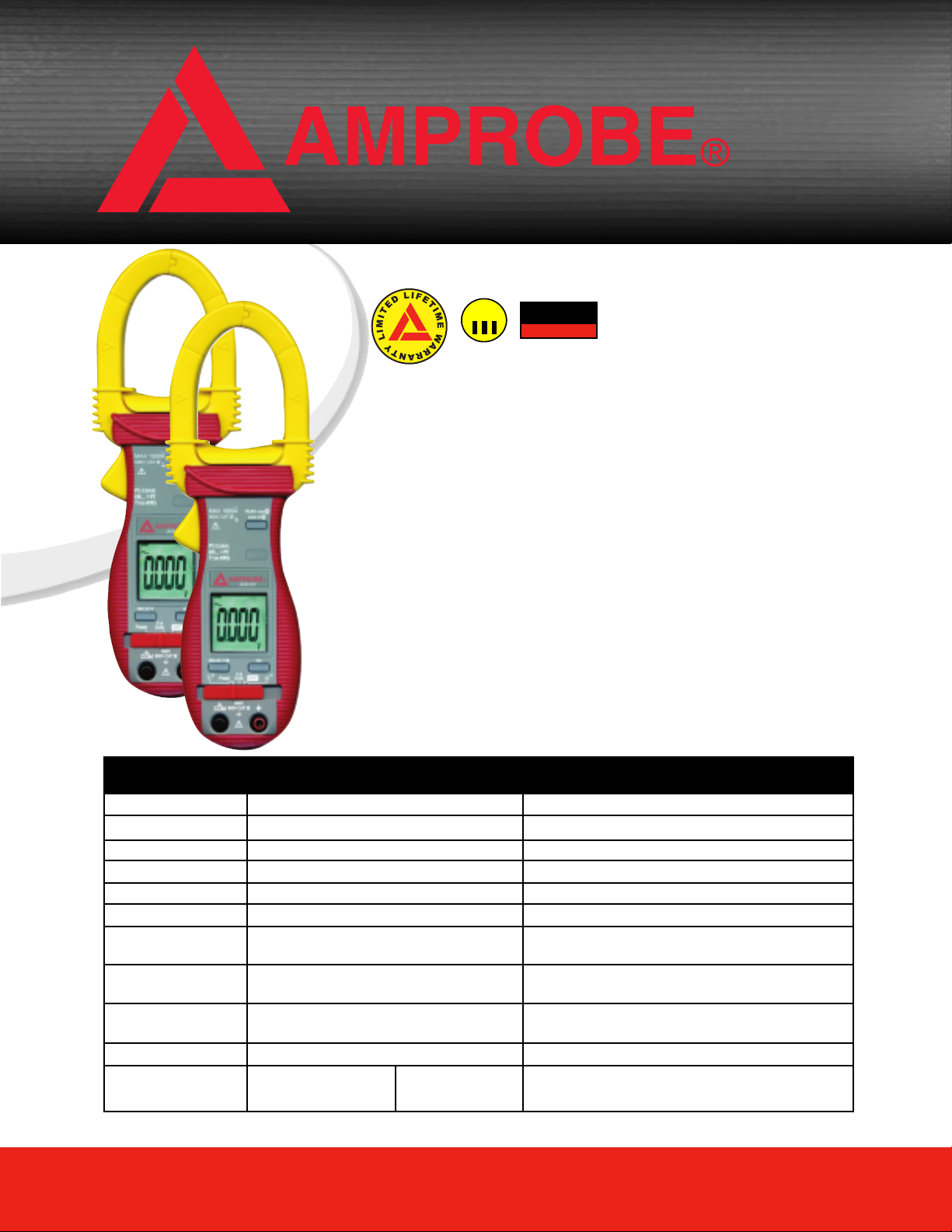
ACD-30P & ACD-31P
1000A Clamp-on Power Meters
CAT
600V
These instruments combine the standard features of professional clamp-on
meters, with full Power analyzing capabilities! Measure: Active (W), Reactive
(VAR) and Apparent (VA) Powers along with dual display Power Factor readout.
Increase measuring efficiency with an optional PC interface kit.
• TRMS sensing
• Back light display (ACD-31P)
• AutoVA - Auto Selection of AC Volts,
DC Volts or AC Amps
• Measurements:
- AC/DC Voltage up to 600V, AC Current
up to 1000A, Resistance, Frequency
- Active (W), Reactive (VAR) & Apparent
(VA) Power with dual-display Power
Factor readout
-Temperature (ACD-31P)
• Optional PC interface capability
• Audible continuity
• Auto power off
TRUE
RMS
z
• Automatic polarity
• Low battery indication
• Peak hold
• Data hold
• Large, easy to read LCD display
• Accommodates conductors up to
1.77” (45mm) in diameter
• Carrying case, test leads,
batteries (installed), thermocouple
(ACD-31P), and manual included
• Voltage overload protection for all
functions up to 600V AC/DC
• Safety CAT III 600V
FEATURES ACD-30P ACD-31P BASIC ACCURACY
TRMS Measuremaent
AC Current
DC Voltage
AC Voltage
Resistance
Frequency
Active Power (W)
Reactive Power (VAR)
Apparent Power (VA)
Power Factor
Temperature
40.0 / 400.0 / 1000 A +/-(1.0% Rdg + 5 LSD) @ 50 and 60Hz
Yes
600.0V +/-(0.5% Rdg + 5 LSD)
600.0V +/-(0.5% Rdg + 5 LSD) @ 50 / 60 Hz
999.9 Ohms +/-(1.0% Rdg + 6 LSD)
5.00Hz to 500.0Hz +/-(0.5% Rdg +4 LSD)
0 to 600.0 kW +/-(2.0% Rdg + 6 LSD) @ Harmonics
Fund to 10th & PF > 0.7
0 to 600.0 kVAR +/-(2.0% Rdg + 6 LSD) @ Harmonics
Fund to 10th & PF > 0.7
0 to 600.0 kVA +/-(2.0% Rdg + 6 LSD) @ Harmonics
Fund to 10th
0.10 to 0.99 +/- 3 LSD @ Harmonics Fund to 21th
-58 F to 572 F
(-50 C to 300 C)
+/-(2.0% Rdg + 6F)
+/-(2.0 % Rdg + 3C)
www.AMPROBE.com
Page 2
CAT
600V
TRUE
RMS
z
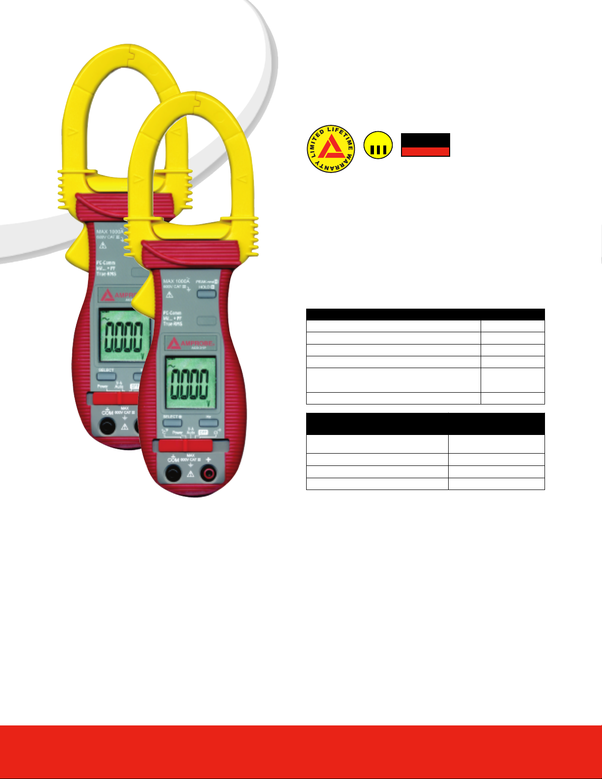
These instruments combine the standard features of
professional clamp-on meters, with full Power
analyzing capabilities! Measure: Active (W), Reactive
(VAR) and Apparent (VA) Powers along with dual display Power Factor readout. Increase measuring
efficiency with an optional PC interface kit.
OPTIONAL ACCESSORIES PART NUMBER
PC Interface kit (PC connection cable with software) RS-232 KIT2
Line splitter (Energizer) A47L
5000A Clamp-on Current Transformer (50 to 1) CT50-1
3000A Clamp-on Current Transformer (50 to 1) CT50-2
Dual input Thermocouple adapter with two thermocouples -50°F to 600°F
Alligator Clips (For test leads) VRC-320
DKTA-620 and
two of TPK-56
Update Rate:
Power function: 1 per second nominal
ACA clamp-on, Ohm, Hz & Temperature
oltage,
V
functions: 4 per second nominal
Polarity: Automatic
Low Battery: Below approx. 2.4V
Operating Temperature: 0˚C to 40˚C
Relative Humidity: Maximum relative humidity
80% for temperature up to 31˚C decreasing
linearly to 50% relative humidity at 40˚C
Altitude: Operating below 2000m
Storage Temperature: -20˚C to 60˚C, < 80%
R.H. (with battery removed)
Temperature Coefficient: nominal 0.15 x (spec
ified accuracy)/ ˚C @(0˚C -18˚C or
28˚C -40˚C), or otherwise specified
Sensing: True RMS sensing for all models
Safety: Meets IEC61010-2-032 (1994),
EN61010-2-032(1995), UL3111-2-032(1999).
Measurement Category: III 600 Volts ac & dc
REPLACEMENT PARTS
(supplied with product)
Test leads with set of alligator clips
(alligator clips are not supplied with product)
Thermocouple TPK-59
Carrying case SV-U
Instruction Manual
Transient protection: 6.5kV (1.2/50µs surge)
for all models
Pollution degree: 2
E.M.C.: Meets EN61326(1997, 1998/A1),
EN61000-4-2(1995), and EN61000-4-3(1996)
an RF field of 3V/m:
otal Accuracy = Specified Accuracy + 45 digits
T
erformance above 3V/m is not specified
Overload Protections: ACA
rms continuous + & COM terminals (all
1000A
functions): 600VDC/V
Power Supply : standard 1.5V
or IEC LR03) battery X 2
24A
-
Power Consumption: V
Power functions: 10mA
HM & Temperature functions: 4mA typical
APO Timing: Idle for 17 minutes
APO Consumption: 10µA typical
Dimension: L224mm X W78mm X H40mm
Weight: 224 gm approx
Clamp-on jaws: AC
AC RMS
AAA Size (NEDA
oltage, ACA, Hz &
typical
PART NUMBER
MTL-90B
.AMPROBE.com
www
Jaw opening & Conductor diameter: 45mm max
Special features: Backlight display (model ACD-
31P & ACD-41PQ only); AutoVATM
(Auto Selection on ACV, DCV or ACA functions);
Power measurement of selectable W,
VAR & VA with dual-display Total Power Factor
features; Total harmonic distortion THD%-F
(model ACD-41PQ only); PEAK-rms HOLD
ELECTRICAL SPECIFICATIONS
Accuracy is ±(% reading digits + number of digits) or otherwise specified, at 23 oC ±5 oC
less than 75% R.H. & True RMS (all models)
ACV & ACA clamp-on accuracies are specified
from 0% to 100% of range or otherwise specified. Maximum Crest Factor is as specified
below, and with frequency spectrums, besides
fundamentals, fall within the meter specified AC
bandwidth for non-sinusoidal waveforms.
Fundamentals are specified at 50Hz and 60Hz.
www.AMPROBE.com
Page 3

AC Voltage
RANGE Accuracy
50Hz / 60Hz
600.0V 0.5% + 5d
45Hz ~ 500Hz
600.0V
1.5% + 5d
500Hz ~ 3.1kHz 9 (ACD-16 TRMS only)
600.0V 2.5% + 5d
CMRR: >60dB @ DC to 60Hz, Rs=1kΩ
Input Impedance: 2MΩ, 30pF nominal
Crest Factor: < 2.3 : 1 at full scale & < 4.6: 1 at half scale
ACV AutoVATM Threshold: 30VAC (40Hz ~ 500Hz only)
nominal
DC Voltage
RANGE Accuracy
600.0V 0.5% + 5d
NMRR: >50dB @ 50/60Hz
CMRR: >120dB @ DC, 50/60Hz, Rs=1kΩ
Input Impedance: 2MΩ, 30pF nominal
DCV AutoVATM Threshold: 2.4VDC nominal
Ohms
RANGE Accuracy
999.9Ω 1.0% + 6d
Open Circuit Voltage: 0.4VDC typical
Audible Continuity Tester
Audible threshold: between 10Ω and 300Ω.
Response time: 250µs
ACA Current (Clamp-on)
RANGE Accuracy
1) 2)
50Hz / 60Hz
40.00A, 400.0A, 1000A 1.0% + 5d
45Hz ~500Hz
40.00A, 400.0A 2.0% + 5d
1000A 2.5% + 5d
500Hz ~ 3.1kHz
40.00A, 400.0A 2.5% + 5d
1000A 3.0% + 5d
ACA AutoVATM Threshold: 1A AC (40Hz ~ 500Hz only)
nominal
Crest Factor:
< 2.5:1 at full scale & < 5.0:1 at half scale for 40.00A &
ranges
400.0A
< 1.4:1 at full scale & < 2.8:1 at half scale for 1000A range
1)
Induced error from adjacent current-carrying conductor:
< 0.06A/A
2)
Specified accuracy is from 1% to 100% of range and for
measurements made at the jaw center
conductor is not positioned at the jaw center, position
errors introduced are: Add 1% to specified accuracy for
measurements made WITHIN jaw marking lines away
from jaw opening) Add 4% to specified accuracy for
measurements made BEYOND jaw marking lines toward
jaws opening)
. When the
Temperature (ACD-31P only)
RANGE Accuracy
1)
-50˚C ~ 300˚C 2.0% + 3˚C
-58˚F ~ 572˚F 2.0% + 6˚F
1)
Add 3˚C (or 6˚F) to specified accuracy @
-20˚C ~ -50˚C (or @ -4˚F ~ -58˚F)
Type-K thermocouple range & accuracy not included
otal Power Factor (PF)
T
RANGE Accuracy
1)
0.10 ~ 0.99 F ~ 21st 22nd ~ 51st
3d 5d
1)
Specified accuracy @ ACA fundamental
Frequency
RANGE Accuracy
5.00Hz ~ 500.0Hz 0.5%+4d
Sensitivity (Sine RMS)
40A range: > 4A
400A range: > 40A
1000A range: > 400A
600V range: > 30V
Frequency
RANGE Accuracy
5.00Hz ~ 500.0Hz 0.5%+4d
40A range: > 4A
> 2A ; ACV fundamental > 50V
Power
RANGE Accuracy
1) 2)
0 ~ 600.0kVA F ~ 10th 11th ~ 46th 47th ~ 51st
@ PF = 0.99 ~ 0.1
RANGE Accuracy
2.0%+6d 3.5%+6d 5.5%+6d
1) 3)
0 ~ 600.0kW / kVAR F ~ 10th 11th ~ 25th 26th ~ 46th 47th ~ 51st
@ PF = 0.99 ~ 0.70
@ PF = 0.70 ~ 0.50
@ PF = 0.50 ~ 0.30
@ PF = 0.30 ~ 0.20
1)
Specified accuracy is for ACA clamp measurement at the center of jaws. When the
conductor is not positioned at the jaw center
2.0%+6d 3.5%+6d 4.5%+6d
3.0%+6d
4.5%+6d
10%+6d 15%+6d
, position errors introduced are:
10%+6d
Add 1% to specified accuracy for ACA measurements made WITHIN jaw marking
lines (away from jaw opening)
measurement made BEYOND jaw marking lines
Accuracy is not specified for
ACA
(toward jaws opening)
2)
Add 1% to specified accuracy @ ACA fundamental < 5A or ACV fundamental < 90V.
Accuracy is not specified @ ACA fundamental < 1A or ACV fundamental < 30V
3)
Add 1% to specified accuracy @
fundamental < 5A or ACV fundamental < 90V.
ACA
Accuracy is not specified @ ACA fundamental < 2A or ACV fundamental < 50V
A-lags 1)Indication:
lags
“A-lags” LCD annunciator turns on to indicate an inductive circuit, or Current
A
Voltage V (i.e., phase-shift angle£c is “+”).
1)
A-lags Indication is specified at 50/60Hz fundamental without harmonics, and at ACV >
90V, ACA > 9A, & PF < 0.95
www.AMPROBE.com
Page 4

ACD-30P & ACD-31P
1000A Clamp-on Power Meters
Miramar, FL 33025 • Toll Free: 800-327-5060 • Phone: 954-499-5400 • Fax: 866-287-7222 • www.Amprobe.com
www.AMPROBE.com
 Loading...