

Page 1

ACD-20SW
ACD-21SW
ACD-21SWC
Digital Clamp Meter
Users Manual
• Mode d’emploi
• Bedienungshandbuch
• Manual d’Uso
• Manual de uso
Page 2

Page 3

ACD-20SW
ACD-21SW
ACD-21SWC
Digital Clamp Meter
Users Manual
September 2009, Rev.2
©2009 Amprobe Test Tools.
All rights reserved. Printed in Taiwan
English
Page 4

Limited Warranty and Limitation of Liability
Your Amprobe product will be free from defects in material and workmanship for 1 year from the date of
purchase. This warranty does not cover fuses, disposable batteries or damage from accident, neglect, misuse,
alteration, contamination, or abnormal conditions of operation or handling. Resellers are not authorized
to extend any other warranty on Amprobe’s behalf. To obtain service during the warranty period, return
the product with proof of purchase to an authorized Amprobe Test Tools Service Center or to an Amprobe
dealer or distributor. See Repair Section for details. THIS WARRANTY IS YOUR ONLY REMEDY. ALL OTHER
WARRANTIES - WHETHER EXPRESS, IMPLIED OR STAUTORY - INCLUDING IMPLIED WARRANTIES OF FITNESS
FOR A PARTICULAR PURPOSE OR MERCHANTABILITY, ARE HEREBY DISCLAIMED. MANUFACTURER SHALL
NOT BE LIABLE FOR ANY SPECIAL, INDIRECT, INCIDENTAL OR CONSEQUENTIAL DAMAGES OR LOSSES,
ARISING FROM ANY CAUSE OR THEORY. Since some states or countries do not allow the exclusion or
limitation of an implied warranty or of incidental or consequential damages, this limitation of liability may
not apply to you.
Repair
All test tools returned for warranty or non-warranty repair or for calibration should be accompanied by the
following: your name, company’s name, address, telephone number, and proof of purchase. Additionally,
please include a brief description of the problem or the service requested and include the test leads with
the meter. Non-warranty repair or replacement charges should be remitted in the form of a check, a money
order, credit card with expiration date, or a purchase order made payable to Amprobe® Test Tools.
In-Warranty Repairs and Replacement – All Countries
Please read the warranty statement and check your battery before requesting repair. During the
warranty period any defective test tool can be returned to your Amprobe® Test Tools distributor for an
exchange for the same or like product. Please check the “Where to Buy” section on www.amprobe.com
for a list of distributors near you. Additionally, in the United States and Canada In-Warranty repair and
replacement units can also be sent to a Amprobe® Test Tools Service Center (see next page for address).
Non-Warranty Repairs and Replacement – US and Canada
Non-warranty repairs in the United States and Canada should be sent to a Amprobe® Test Tools
Service Center. Call Amprobe® Test Tools or inquire at your point of purchase for current repair and
replacement rates.
In USA In Canada
Amprobe Test Tools Amprobe Test Tools
Everett, WA 98203 Mississauga, ON L4Z 1X9
Tel: 888-993-5853 Tel: 905-890-7600
Fax: 425-446-6390 Fax: 905-890-6866
Non-Warranty Repairs and Replacement – Europe
European non-warranty units can be replaced by your Amprobe® Test Tools distributor for a nominal
charge. Please check the “Where to Buy” section on www.amprobe.com for a list of distributors near
you.
Amprobe® Test Tools Europe
In den Engematten 14
79286 Glottertal, Germany
tel: +49 (0) 7684 8009 - 0
*(Correspondence only – no repair or replacement available from this address. European customers
please contact your distributor.)
Page 5

14
15
8
9
13
12
11
1010
1
2
7
6
5
4
3
8
9
12
11
1
2
7
6
5
4
3
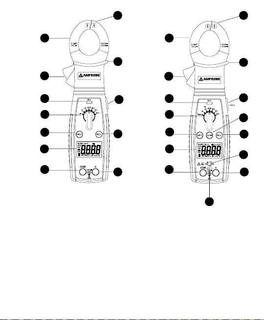
ACD-21SWC
ACD-20SW
1. Current Jaws
2. Jaw Opening Lever
3. NCV LED indicator
4. Function Selector Knob
5. Range push button selector
6. LCD Display 3 ¾ digit with 3999
counts
7. Common (Ground reference) Input
jack for all functions EXCEPT
clamp-on ACA current function
8. Input jack for all functions EXCEPT
clamp-on ACA current function
9. NCV Push button function
10. NCV Sensor
11. Hand/Finger Barrier to indicate
the limits of safe access of the
meter during measurement
12. Hold Push button function
13. Ohm/Continuity push button
function
14. Input jacks for temperature
measurement
15. Temperature Slide Knob
Page 6

CONTENTS
SYMBOLS ............................................................................................................ 2
Safety Information.........................................................................................2
UNPACKING AND INSPECTION .......................................................................... 4
INTRODUCTION ..................................................................................................4
OPERATION .........................................................................................................5
HOLD Button ..................................................................................................5
RANGE Button................................................................................................5
Measuring DC Voltage...................................................................................5
Measuring AC Voltage...................................................................................5
AC Current Measurement .............................................................................5
Capacitance Measurement (ACD-21SW / ACD-21SWC only) ....................... 6
Resistance ....................................................................................................... 6
Continuity Testing ..........................................................................................6
Diode Testing (ACD-20SW) ............................................................................7
Temperature Measurement (ACD-21SW / ACD-21SWC only) .....................7
Non-Contact Voltage Indicator .....................................................................7
Auto Power off ..............................................................................................8
Cancellation of Auto Power off feature: .....................................................8
SPECIFICATIONS .................................................................................................8
DC Volts .......................................................................................................... 9
AC Volts .......................................................................................................... 9
AC Current......................................................................................................9
Resistance ....................................................................................................... 9
Capacitance (ACD-21SW / ACD-21SWC only) ............................................10
Temperature (ACD-21SW / ACD-21SWC only) ...........................................10
Continuity.....................................................................................................10
(NCV) Non-Contact Voltage Indicator ........................................................10
Diode Test (ACD-20SW only) .......................................................................11
Battery Replacement ...................................................................................11
MAINTENACE AND REPAIR ..............................................................................11
1
Page 7
SYMBOLS
Battery
Double Insulated
T
Alternating Current
B
Direct Current
F
Application around and
removal from hazardous live
,
conductors is permitted
Do not dispose of this product
=
as unsorted municipal waste
Canadian Standards Association (NRTL/C)
)
Refer to the manual
W
Earth Ground
J
Fuse
I
Complies with EU directives
P
Conform to relevant
;
Australian standards
Audible tone
m
Safety Information
• The ACD-20SW, ACD-21SW and ACD-21SWC swivel Clamp meters conform
to EN61010-1:2001; EN61010- 2-032:2002; CAT III 600 V, class II; pollution
deg.2 and EN61326-1 (EMC compliance)
• This instrument is EN61010-1 certied for Installation Category III (600V).
It is recommended for use in primary supply lines, overhead lines and
cable systems and distribution level and xed installations, as well as lesser
installations.
• Do not exceed the maximum overload limits per function (see
specications) nor the limits marked on the instrument itself. Never apply
more than 600 V ac rms between the test lead and earth ground.
WWarnings and Precautions
• Before and after hazardous voltage measurements, test the voltage
function on a known source such as line voltage to determine proper
meter functioning.
• Disconnect the test leads from the test points before changing meter
functions.
• Disconnected from the meter’s test leads before measuring current.
2
Page 8

• Inspect the Clamp meter, test leads and accessories before every use. Do
not use any damaged part.
• Never ground yourself when taking measurements. Do not touch exposed
circuit elements or test probe tips.
• Do not operate the instrument in an explosive atmosphere.
• To reduce the risk of re or electric shock, do not expose this product to
rain or moisture.
• The meter is intended only for indoor use. To avoid electrical shock hazard,
observe the proper safety precautions when working with voltages above
60 VDC, 42.4 Vpk, or 30 VAC rms. These voltage levels pose a potential
shock hazard to the user.
• Before and after hazardous voltage measurements, test the voltage
function on a known source such as line voltage to determine proper
meter functioning.
• Keep your hands/ngers behind the hand/nger barriers (of the meter and
the test leads) that indicate the limits of safe access of the hand-held part
during measurement.
• Inspect test leads, connectors, and probes for damaged insulation or
exposed metal before using the instrument. If any defects are found,
replace them immediately.
• This Clamp-on meter is designed to apply around or remove from un-
insulated hazardous live conductors. Individual protective equipment must
be used if hazardous live parts of the installation could be accessible.
• Exercise extreme caution when: measuring voltage >20 V // current >10
mA // AC power line with inductive loads // AC power line during electrical
storms // current, when the fuse blows in a circuit with open circuit voltage
>600 V // servicing CRT equipment.
• Remove test leads before opening the case to change the battery.
• Disconnect circuit power and discharge all high-voltage capacitors before
testing resistance, continuity, diodes, or capacitance.
• To avoid false readings, which could lead to possible electric shock or
personal injury, replace the batteries as soon as the low battery indicator
( ) appears.
• To avoid electric shock hazard, do not use the HOLD mode to determine if
a circuit is live. Unstable readings will not be captured and displayed.
WCAUTION
For non-invasive ACA current measurements, clamp the jaws around only
one single conductor of a circuit for load current measurement. More than 1
conductor will cause false readings
3
Page 9

UNPACKING AND INSPECTION
Your shipping carton should include:
1 ACD-20SW, ACD-21SW or ACD-21SWC Swivel Clamp Meter
1 Set of Test leads
1 Soft Carrying Case
1 Users Manual
1 Type K Thermocouple probe (Model ACD-21SW / ACD-21SWC only)
2 1.5V AAA Batteries (Installed)
If any of the items are damaged or missing, return the complete package to the
place of purchase for an exchange.
INTRODUCTION
The ACD-20SW, ACD-21SW and ACD-21SWC clamp-On meters come with a new
patented rotating head design that allows easy viewing of the measurements in
tight or inconvenient to reach places. Simply rotate the body of the meter to get
an unobstructed view of the LCD display. Rich set of features and CAT III 600V
safety reading for use in electrical and HVAC applications.
The features include:
• 180 degree rotating head for the perfect display viewing
• Advanced VoltTect non-contact voltage detection
• Slim jaw design with one hand operation
• Measures AC Current up to 400 ACA, AC/DC Voltage up to 600V,
• Resistance and Capacitance(ACD-21SW / ACD-21SWC only)
• Temperature measurement (ACD-21SW / ACD-21SWC only)
• Audible continuity
• Auto and manual ranging respectively for quick checks and precise
measurements
• Auto power off
• Data hold
• Diode Test (ACD-20SW only)
• Accommodates conductors up to 1.18” (30mm) in diameter
4
Page 10

OPERATION
HOLD Button
Data hold freezes the reading present on the LCD at the moment the button is
pressed.To use this menu feature, set up the meter for the type of measurement
and range desired.
Connect the test leads to the circuit / component to be measured and then press
“HOLD” push button. The LCD reading will freeze and display “HOLD.” You may
now remove the test leads and the reading will not change until you press Hold
again.
RANGE Button
This function allows the user to select the range of a function that does not show
‘RANGE’ on the LCD.
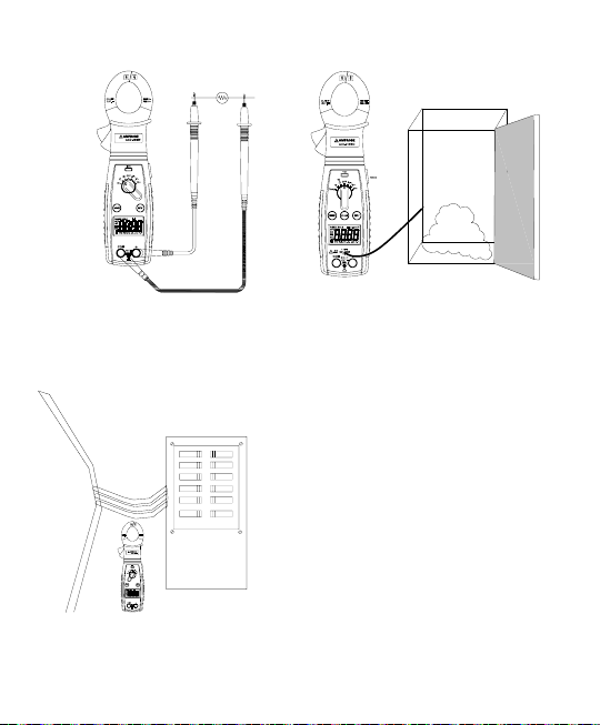
Measuring DC Voltage
1. Set the Function Switch to L
2. Connect the test leads: Red to +, Black to COM.
3. Connect the test probes to the circuit test points. Refer to Fig.1
4. Read the display. If necessary, correct any overload ( 0L) conditions.
Measuring AC Voltage
1. Set the Function Switch to K.
2. Connect the test leads: Red to +, Black to COM.
3. Connect the test probes to the circuit test points. Refer to Fig.2
4. Read the voltage on the primary display and the frequency on the
secondary display. If necessary, correct any overload (0L) conditions.
AC Current Measurement
1. Set the Function Switch to position ?.
2. Open spring-loaded clamp by pressing the jaw opening lever on the left
side of meter.
3. Position clamp around one wire or conductor. Release the jaw opening
lever. Wire should be center inside the jaws. Refer to Fig.3
4. Read the current on the primary display and the frequency on the
secondary display. If necessary, correct any overload (OL) conditions.
5
Page 11
Capacitance Measurement (ACD-21SW / ACD-21SWC only)
When testing a capacitor that is part of a circuit, if “dS.C” is displayed on the
screen, a voltage is present. Discharge the capacitor before testing.
1. Sett the Function Switch to “ E ” position.
2. Connect the test leads: Red to +, Black to COM.
3. Connect the test probes to the circuit test points. Refer to Fig. 4
4. Read the display. If necessary, correct any overload (0L) conditions.
WCAUTION
Using the Resistance or Continuity function in a live circuit will produce false
results and may damage the instrument. In most cases the suspected component
must be disconnected from the circuit to obtain an accurate reading.
Resistance
1. Set the Function Switch to e. Use the “e/R“ button to select the
resistance test (ACD-21SW / ACD-21SWC only).
2. Connect the test leads: Red to +, Black to COM.
3. Turn off power to the circuit being measured. Never measure resistance
across a voltage source or on a powered circuit.
4. Discharge any capacitors that may influence the reading.
5. Connect the test probes across the resistance. Refer to Fig.5
6. Read the display. If 0L appears on the highest Range, the resistance is too
large to be measured or the circuit is an open circuit.
Continuity Testing
1. Set the Function Switch to e. Use the “e/R“ button to select the test
(ACD-21SW / ACD-21SWC only).
2. Connect the test leads: Red to +, Black to COM.
3. Turn off power to the circuit being measured.
4. Discharge any capacitors that may influence the reading.
5. Connect the test probes across the resistance or the two points of test
6. Listen for the tone that indicates continuity (< 25e).
6
Page 12

Diode Testing (ACD-20SW)
1. Set the Function Swith to “ “ position.
2. Connect the red test lead to the “Ve” jack and the black test lead to the
“COM” jack.
3. Turn off power to the circuit under test. External voltage across the
components may cause invalid readings.
4. Connect the probes to the diode. A forward-voltage drop is about 0.6V
(typical for a silicon diode).
5. Reverse probes connection with the diode. If the diode is good, “OL”
isdisplayed. If the diode is shorted, “0.00” or another number is displayed.
6. If the diode is open, “OL” is displayed in both directions.
7. Audible Indication: Less than 0.25V.
Temperature Measurement (ACD-21SW / ACD-21SWC only)
1. Verify that the location being tested is not electrically energized.
2. Set the Function Switch to Temp position.
3. Move the slide knob to the TEMP position. Insert the thermocouple plug
matching the slot widths.
4. Connect the thermocouple bead to the test point. Refer to Fig.6
5. Read the display. If 0L appears on the display, the temperature is too large
to be measured or the thermocouple is open.
6. ACD-21SW - Fahrenheit
ACD-21SWC - Celsius
7. Setting up for 400°C or 400°F measurements: Open bottom case, and nd
the jumper (next to jack) on (400°C) when the jumper is short, and reads in
degree Fahrenheit (400°F) when the jumper is open.
Note: The test leads must be removed to move the slide plate to allow the
thermocouple to be inserted.
Non-Contact Voltage Indicator
1. Remove the test leads from the meter. Push the “NCV” button at any
selected function/Range. Then the display will be shut down and LED
flashes with a short “chirp” sound for self-test. Refer to Fig. 7
2. With the NCV tab on the tip of the clamp close to an AC voltage, Press the
“NCV” button, the NCV LED will light and the beeper will beep. The closer
you get to AC voltage, the louder the beep.
7
Page 13

Auto Power off
1. Auto power off: approx. 10 minutes.
2. After auto power off, press any button to restart the meter, and the
reading of measurement will be maintained in the display.
Cancellation of Auto Power off feature:
• Press and hold the (RANGE) button while rotating function switch from off
to any position to turn the meter on.
• The auto power off feature is disabled.
• Note “APO” annunciator is missing from the LCD.
SPECIFICATIONS
Display: 3¾ digit liquid crystal display (LCD) with a maximum reading of 3999.
Polarity: Automatic, positive implied, negative polarity indication.
Over range: (OL) or (-OL) is displayed.
Zero: Automatic.
Low battery indication: The “ ” is displayed when the battery voltage drops
below the operating level.
Measurement rate: 2 times per second, nominal.
Auto power off: Approx. 10 minutes.
Operating environment: 0°C to 50°C(32°F to 122°F) at < 70% relative humidity.
Storage temperature: -20°C to 60°C(-4°F to 140°F) at < 80% relative humidity.
Accuracy: Stated accuracy at 23°C±5°C, <75% relative humidity.
Temperature Coefcient: 0.1 × (specied accuracy) per °C. (0°C to 18°C, 28°C to
50°C).
Altitude: 6561.7 Feet (2000m).
Jaw opening capability: 30mm conductor.
Power: 1.5 volt battery x2, R03/SIZE AAA.
Battery life:75 hours typical with carbon-zinc (ACD-21SW /ACD-21SWC)
Dimensions: 240 × 70 × 41 mm (9.5 x 2.8 x 16 IN).
Weight: Approx. 7.7 oz. (220g).
75 hours typical with carbon-zinc (ACD-20SW)
8
Page 14

DC Volts
Ranges Resolution Accuracy
400mV, 4V, 40V, 400V, 600V 0.1mV ±(0.5% rdg + 2 dgts)
Input impedance: 400mV: >100Me; 4V: 10Me; 40V ~ 600V: 9.1Me
Overload protection: 600VDC or AC rms
AC Volts (50Hz - 500Hz)
Ranges Resolution Accuracy
4V, 40V, 400V 1mV ±(1.2% rdg + 5 dgts) on 4V to 400V ranges
600V 1mV ±(1.5% rdg + 5 dgts) on 600V range
Input impedance: 4V: 10Me; 40V ~ 600V: 9.1Me
Overload protection: 600VDC or AC rms
AC Current (50Hz - 60Hz)
Ranges Resolution Accuracy
40A, 400A 0.01A ±(2.0% rdg + 6 dgts)
Overload protection: 400AAC
Resistance
Ranges Resolution Accuracy
400e, 4ke, 40ke, 400ke 0.1e ±(1.0% rdg + 4 dgts)
4Me 0.1e ±(1.5% rdg + 4 dgts)
40Me 0.1e ±(3.0% rdg + 5 dgts)
Open circuit volts: -0.45V dc typical, (-1.2Vdc on 400e range)
Overload protection: 600VDC or AC rms
9
Page 15

Capacitance (ACD-21SW / ACD-21SWC only)
Ranges Resolution Accuracy
4μF 1nF ±(3.0% rdg + 15 dgts)
40μF, 400μF 1nF ±(3.0% rdg + 5 dgts)
4mF 1nF ±(5.0% rdg + 20 dgts)
Minimum input range: >100nF
4nF, 40nF, 400nF ranges unspecied
When the capacitor to be tested is connected, if “dS.C” symbol indicates on
LCD, it means there is voltage existing in the tested capacitor and need to be
discharged before testing.
Overload protection: 600VDC or AC rms
Temperature (ACD-21SW / ACD-21SWC only)
Range -35°C ~ 400°C, -30°F ~ 400°F,
Resolution 0.1°F, 0.1°C
Accuracy
Sensor type: K-type thermocouple
Overload protection: 30V Max
±(1.0% + 2°F) 32°F ~ 400°F ±(1.0% + 1°C) 0°C ~ 400°C
±(2.0% + 6°F) -30°F ~ 32°F ±(2.0% + 3°C) -35°C ~ 0°C
Continuity
Range: 400e
Resolution: 1e
Audible indication: Less than 25e
Response time: 500ms
Overload protection: 600VDC or AC rms
(NCV) Non-Contact Voltage Indicator
Detect voltage from 70V to 600VAC (50Hz ~ 60Hz)
Red LED and audible indicator
10
Page 16
Diode Test (ACD-20SW only)
Test current: 0.8mA (approximate)
Accuracy: ±(3.0% rdg + 3 dgts)
Resolution: 10mV
Open circuit volts: 3.0Vdc typical
Audible indication: < 0.25V
Overload protection: 600VDC or AC rms
Battery Replacement
• Power is supplied by 1.5 volt battery x2 (LR03/SIZE AAA ).
• The “ “ appears on the LCD display when replacement is needed.
• To replace the battery, remove the two screws from the back of the meter
and lift off the front case.
• Remove the battery from case bottom.
MAINTENACE AND REPAIR
If there appears to be a malfunction during the operation of the meter, the
following steps should be performed in order to isolate the cause of the
problem.
1. Check the battery. Replace the battery immediately when the symbol
“ ” appears on the LCD.
2. Review the operating instructions for possible mistakes in operating
procedure.
Except for the replacement of the battery, repair of the meter should be
performed only by a Factory Authorized Service Center or by other qualied
instrument service personnel. The front panel and case can be cleaned with a
mild solution of detergent and water. Apply sparingly with a soft cloth and allow
to dry completely before using. Do not use aromatic hydrocarbons or chlorinated
solvents for cleaning.
11
Page 17
ACD-20SW
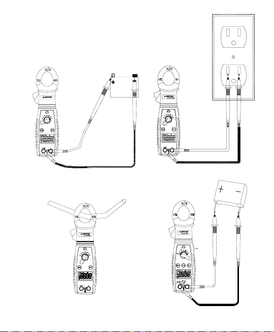
Fig.1 Measuring DC Voltage
Fig.2 Measuring AC Voltage
Fig.3 Measuring AC Current Fig.4 Measuring Capacitance
12
Page 18
ON
ON
ON
ON
ON
ON
OFF
OFF
OFF
OFF
OFF
OFF
OFF
OFF
OFF
OFF
OFF
OFF
Fig.5 Measuring Resistance
Fig.6 Measuring Temperature
Fig.7 Non-Contact voltage (NCV) Measurement
13
Page 19

ACD-20SW
ACD-21SW
ACD-21SWC
Pince multimètre numérique
Mode d’emploi
Septembre 2009, rév. 2
©2009 Amprobe Test Tools.
Tous droits réservés. Imprimé à Taïwan.
Français
Page 20

Limites de garantie et de responsabilité
Amprobe garantit l’absence de vices de matériaux et de fabrication de ce produit pendant une période d’un
an prenant effet à la date d’achat. Cette garantie ne s’applique pas aux fusibles, aux piles jetables ni à tout
produit mal utilisé, modié, contaminé, négligé ou endommagé par accident ou soumis à des conditions
anormales d’utilisation et de manipulation. Les revendeurs n’ont pas l’autorisation de prolonger toute autre
garantie au nom d’Amprobe. Pour bénécier de la garantie, renvoyez le produit accompagné d’un justicatif
d’achat auprès d’un centre de services agréé par Amprobe Test Tools ou d’un distributeur ou d’un revendeur
Amprobe. Voir la section Réparation pour tous les détails. LA PRESENTE GARANTIE EST LE SEUL ET EXCLUSIF
RECOURS DE L’UTILISATEUR. TOUTES AUTRES GARANTIES, EXPLICITES, IMPLICITES OU STATUTAIRES,
NOTAMMENT LES GARANTIES DE QUALITE MARCHANDE OU D’ADAPTATION A UN OBJECTIF PARTICULIER
SONT EXCLUES PAR LES PRESENTES. LE FABRICANT NE SERA EN AUCUN CAS TENU RESPONSABLE DE
DOMMAGES PARTICULIERS, INDIRECTS, ACCIDENTELS OU CONSECUTIFS, NI D’AUCUNS DEGATS OU PERTES
DE DONNEES, SUR UNE BASE CONTRACTUELLE, EXTRA-CONTRACTUELLE OU AUTRE. Etant donné que
certaines juridictions n’admettent pas les limitations d’une condition de garantie implicite ou l’exclusion ou la
limitation de dégâts accidentels ou consécutifs, il se peut que les limitations et les exclusions de cette garantie
ne s’appliquent pas à votre cas.
Réparation
Tous les outils de test renvoyés pour être réparés au titre de la garantie doivent être accompagnés des
éléments suivants : nom, raison sociale, adresse, numéro de téléphone et justicatif d’achat. Ajoutez
également une brève description du problème ou du service demandé et incluez les cordons de test avec
l’appareil. Les frais de remplacement ou de réparation hors garantie doivent être acquittés par chèque,
mandat, carte de crédit avec date d’expiration, ou par bon de commande payable à l’ordre de
Amprobe® Test Tools.
Remplacements et réparations sous garantie – Tous pays
Veuillez lire la déclaration de garantie et vériez la pile avant de demander une réparation. Pendant
la période de garantie, tout outil de test défectueux peut être renvoyé auprès de votre distributeur
Amprobe® Test Tools pour être échangé contre un produit identique ou similaire. Consultez la section
« Where to Buy » sur le site www.amprobe.com pour obtenir la liste des distributeurs dans votre région.
Les appareils sous garantie devant être remplacés ou réparés au Canada et aux Etats-Unis peuvent
également être envoyés dans un centre de services Amprobe® Test Tools (voir les adresses ci-dessous).
Remplacements et réparations hors garantie – Canada et Etats-Unis
Les appareils à réparer hors garantie au Canada et aux Etats-Unis doivent être envoyés dans un centre
de services Amprobe® Test Tools. Appelez Amprobe® Test Tools ou renseignez-vous auprès de votre lieu
d’achat pour connaître les tarifs en vigueur de remplacement ou de réparation.
Aux Etats-Unis Au Canada
Amprobe Test Tools Amprobe Test Tools
Everett, WA 98203 Mississauga, ON L4Z 1X9
Tél. : 888-993-5853 Tél. : 905-890-7600
Fax : 425-446-6390 Fax : 905-890-6866
Remplacements et réparations hors garantie – Europe
Les appareils européens non couverts par la garantie peuvent être remplacés par votre distributeur
®
Amprobe
Test Tools pour une somme nominale. Consultez la section « Where to Buy » sur le site
www.amprobe.com pour obtenir la liste des distributeurs dans votre région.
®
Amprobe
Test Tools Europe
In den Engematten 14
79286 Glottertal, Allemagne
Tél. : +49 (0) 7684 8009 - 0
*(Réservée à la correspondance – Aucune réparation ou remplacement n’est possible à cette adresse.
Nos clients européens doivent contacter leur distributeur.)
Page 21
14
15
8
9
13
12
11
1010
1
2
7
6
5
4
3
8
9
12
11
1
2
7
6
5
4
3
ACD-21SWC
ACD-20SW
1. Mâchoire de mesure du courant
2. Levier d’ouverture de mâchoire
3. Témoin à diode NCV
4. Sélecteur rotatif de fonctions
5. Bouton-poussoir sélecteur de gamme
6. Écran LCD, 3 ¾ chiffres et 3999 points
7. Jack d’entrée commune (terre de
référence) pour toutes les fonctions
SAUF fonction de serrage intensité
A c.a.
8. Jack d’entrée pour toutes les
fonctions SAUF fonction de serrage
intensité A c.a.
9. Bouton-poussoir NCV
10. Capteur NCV
11. Collerette de protection des
doigts/de la main pour indiquer
les limites de l’accès sans risque de
l’appareil pendant la mesure
12. Bouton-poussoir de maintien
13. Bouton-poussoir Ohm/Continuité
14. Jacks d’entrée pour la mesure de
la température
15. Molette de température
Page 22

TABLE DES MATIÈRES
SYMBOLES .......................................................................................................... 2
Consignes de sécurité ....................................................................................2
DÉBALLAGE ET INSPECTION ..............................................................................4
INTRODUCTION ..................................................................................................4
FONCTIONNEMENT ............................................................................................5
Bouton HOLD ................................................................................................. 5
Bouton RANGE ...............................................................................................5
Mesure de tension c.c. ................................................................................... 5
Mesure de tension c.a....................................................................................5
Mesure de courant alternatif. .......................................................................5
Mesure de capacitance (ACD-21SW / ACD-21SWC uniquement) ...............6
Résistance ....................................................................................................... 6
Test de continuité .......................................................................................... 6
Test des diodes (ACD-20SW) ..........................................................................7
Mesure de température (ACD-21SW / ACD-21SWC uniquement) .............7
Indicateur de tension sans contact ...............................................................7
Arrêt automatique.........................................................................................8
Annulation de la fonctionnalité d’arrêt automatique ................................ 8
CARACTÉRISTIQUES ...........................................................................................8
Volts c.c. ..........................................................................................................9
Volts c.a. .........................................................................................................9
Courant c.a. .................................................................................................... 9
Résistance ....................................................................................................... 9
Capacitance (ACD-21SW / ACD-21SWC uniquement) ...............................10
Température (ACD-21SW / ACD-21SWC uniquement) .............................10
Continuité ....................................................................................................10
Indicateur de tension sans contact (NCV) ...................................................10
Test des diodes (ACD-20SW uniquement) ..................................................11
Changement de la pile ................................................................................11
ENTRETIEN ET RÉPARATION .............................................................................11
1
Page 23
SYMBOLES
Pile
Double isolation
T
Courant alternatif
B
Courant continu
F
L’application et le retrait
de la pince à proximité de
,
conducteurs sous tension
dangereuse sont autorisés
Ne pas mettre ce produit au
rebut avec les déchets ménagers
=
non triés
Association canadienne de normalisation (NRTL/C)
)
Se reporter au mode
W
d’emploi
Prise de terre
J
Fusible
I
Conforme aux directives
P
de l’UE
Conforme aux directives de
l’association australienne de
;
normalisation
Signal sonore
m
Consignes de sécurité
• Les pinces multimètres rotatives ACD-20SW, ACD-21SW et ACD-21SWC sont
conformes aux normes EN61010-1:2001 ; EN61010- 2-032:2002 ; CAT III 600 V,
classe II ; deg. pollution 2 et EN61326-1 (conformité électromagnétique CEM).
• Cet appareil est certié conforme à la norme EN61010-1 pour les
installations de catégorie III (600 V). Son utilisation est recommandée pour
les lignes du réseau d’alimentation électrique primaire, les lignes aériennes
ou les systèmes câblés, les installations xes, les équipements au niveau
distribution et les installations de catégories inférieures.
• Ne pas dépasser les limites de surcharge maximum par fonction (voir les
caractéristiques techniques) ou les limites indiquées sur l’appareil lui-même.
Ne jamais appliquer plus de 600 V c.a. eff. entre le cordon de test et la terre.
WMises en garde et précautions
• Avant et après les mesures de tensions dangereuses, tester la fonction de
tension sur une source connue, une tension secteur p. ex., pour déterminer
le bon fonctionnement de l’appareil.
• Débrancher les cordons de mesure des points de test avant de changer de
fonction sur le multimètre.
• Débrancher les cordons de mesure du multimètre avant de mesurer
le courant.
2
Page 24

• Inspecter la pince multimètre, les cordons de mesure et les accessoires
avant toute utilisation. Ne pas utiliser de pièce endommagée.
• Ne jamais se relier à la terre en prenant des mesures. Ne toucher ni aux
éléments de circuit exposés ni aux pointes des sondes de test.
• Ne pas utiliser l’appareil dans une atmosphère explosive.
• Pour réduire le risque d’incendie ou d’électrocution, ne pas exposer cet
appareil à l’humidité ou à la pluie.
• Le multimètre est destiné à être utilisé à l’intérieur uniquement.
Pour éviter les chocs électriques, observer les précautions de sécurité
appropriées en intervenant sur des tensions supérieures à 60 V c.c. ou à
42,4 V cr. ou 30 V c.a. eff. Ces niveaux de tension présentent un risque
d’électrocution pour l’utilisateur.
• Avant et après les mesures de tensions dangereuses, tester la fonction de
tension sur une source connue, une tension secteur p. ex., pour déterminer
le bon fonctionnement du multimètre.
• Garder les mains/doigts derrière les collerettes de protection qui indiquent
les limites de sécurité du multimètre et des cordons pendant la mesure.
• Inspecter les cordons de mesure, les connecteurs et les sondes pour
détecter un isolant endommagé ou des parties métalliques exposées avant
d’utiliser l’instrument. Remplacer immédiatement l’élément si des défauts
sont détectés.
• Cette pince multimètre est destinée à être retirée ou appliquée aux
conducteurs sous tension dangereuse non isolés. Utiliser des équipements
de protection individuelle si des pièces sous tension dangereuse risquent
d’être accessibles.
• Faire preuve d’extrême prudence en : mesurant une tension > 20 V // un
courant > 10 mA // les lignes d’alimentation secteur avec charges inductives
// les lignes d’alimentation secteur pendant les orages électriques // un
courant alors que le fusible a sauté dans un circuit avec une tension en
circuit ouvert > 600 V // lors d’une intervention sur un appareil à écran
cathodique.
• Retirer les cordons de mesure avant d’ouvrir le boîtier pour changer la pile.
• Débrancher l’alimentation du circuit et décharger tous les condensateurs à
tension élevée avant de contrôler la résistance, la continuité, les diodes ou
la capacité.
• Pour éviter les mesures erronées, ce qui pose des risques d’électrocution
ou de blessure corporelle, remplacer la pile dès que l’indicateur de pile
déchargée apparaît ( ).
• Pour éviter les chocs électriques, ne pas utiliser le mode de maintien
d’afchage HOLD pour déterminer si un circuit est sous tension. Les
lectures instables ne sont ni capturées ni afchées.
WATTENTION
Pour les mesures de courant A c.a. non invasives, serrer les mâchoires autour
d’un conducteur du circuit pour mesurer le courant de charge. La prise en
compte simultanée de plusieurs conducteurs entraîne des mesures erronées.
3
Page 25

DÉBALLAGE ET INSPECTION
Le carton d’emballage doit inclure les éléments suivants :
1 pince multimètre rotative ACD-20SW, ACD-21SW ou ACD-21SWC
1 jeu de cordons de mesure
1 étui de transport
1 mode d’emploi
1 sonde thermocouple de type K (modèle ACD-21SW / ACD-21SWC
uniquement)
2 piles AAA de 1,5 V (installées)
Si l’un de ces éléments est endommagé ou manquant, renvoyez le contenu
complet de l’emballage au lieu d’achat pour l’échanger.
INTRODUCTION
Les pinces multimètres ACD-20SW, ACD-21SW et ACD-21SWC sont dotées d’une
nouvelle tête rotative brevetée pour faciliter la consultation des mesures dans des
endroits étroits ou difciles d’accès. Il suft de faire pivoter le corps de l’appareil
pour disposer d’une vue sans obstacle de l’écran LCD. Ensemble complet de
fonctionnalités et Mesure de sécurité CAT III 600 V pour l’utilisation dans les
applications électriques et CVC.
Parmi ces fonctionnalités :
• tête rotative à 180 degrés pour une vision parfaite de l’écran
• détection de tension évoluée sans contact VoltTect
• forme élancée de la mâchoire utilisable d’une seule main
• mesure le courant c.a. jusqu’à 400 A c.a., la tension c.a./c.c. jusqu’à 600 V
• résistance et capacitance (ACD-21SW / ACD-21SWC uniquement)
• mesure de température (ACD-21SW / ACD-21SWC uniquement)
• continuité sonore
• dénition manuelle ou automatique de la gamme respectivement pour
des tests rapides ou des mesures précises
• arrêt automatique
• maintien des données afchées
• test des diodes (ACD-20SW uniquement)
• accepte les conducteurs jusqu’au diamètre de 30 mm (1,18 po.)
4
Page 26

FONCTIONNEMENT
Bouton HOLD
Le maintien des données ge la valeur présente sur l’écran LCD au moment de la
pression du bouton. Pour utiliser cette fonction du menu, réglez l’appareil pour le
type de mesure et la gamme souhaités.
Branchez les cordons de mesure au circuit/composant mesuré et appuyez sur le
bouton poussoir HOLD. L’écran LCD ge la valeur afchée et « HOLD » apparaît.
Vous pouvez maintenant retirer les cordons de mesure ; la valeur relevée reste
afchée tant que le bouton HOLD n’est pas enfoncé une nouvelle fois.
Bouton RANGE
Permet à l’utilisateur de sélectionner la gamme d’une fonction qui n’afche pas
« RANGE » sur l’écran LCD.
Mesures de tension c.c.
1. Réglez le commutateur de fonction sur L.
2. Branchez les cordons de mesure : le rouge sur +, le noir sur COM.
3. Branchez les sondes de test aux points de test du circuit. Reportez-vous à
la gure 1.
4. Lisez l’afchage. Si nécessaire, corrigez toute situation de surcharge (0L).
Mesures de tension c.a.
1. Réglez le commutateur de fonction sur K.
2. Branchez les cordons de mesure : le rouge sur +, le noir sur COM.
3. Branchez les sondes de test aux points de test du circuit. Reportez-vous à
la gure 2.
4. Lisez la mesure de tension sur l’écran principal et la mesure de fréquence
sur l’écran secondaire. Si nécessaire, corrigez toute situation de
surcharge (0L).
Mesure de courant alternatif
1. Réglez le commutateur de fonction sur ?.
2. Ouvrez la pince à ressort en appuyant sur le levier d’ouverture de la
mâchoire à gauche de l’appareil.
3. Placez la mâchoire autour d’un l ou conducteur. Relâchez le levier
d’ouverture. Le l doit être centré à l’intérieur des mâchoires. Reportezvous à la gure 3.
4. Lisez la mesure d’intensité sur l’écran principal et la mesure de fréquence
sur l’écran secondaire. Si nécessaire, corrigez toute situation de
surcharge (0L).
5
Page 27

Mesure de capacitance (ACD-21SW/ACD-21SWC uniquement)
Lors des tests d’un condensateur faisant partie d’un circuit, la mention « dS.C »
à l’écran indique la présence d’une tension. Déchargez le condensateur avant
les tests.
1. Réglez le commutateur de fonction sur E.
2. Branchez les cordons de mesure : le rouge sur +, le noir sur COM.
3. Branchez les sondes de test aux points de test du circuit. Reportez-vous à
la gure 4.
4. Lisez l’afchage. Si nécessaire, corrigez toute situation de surcharge (0L).
WATTENTION
L’utilisation des fonctions de résistance ou de continuité sur un circuit sous
tension produit des résultats erronés et risque d’endommager l’instrument. Dans
la plupart des cas, le composant à l’origine du problème doit être débranché du
circuit pour obtenir une mesure précise.
Résistance
1. Réglez le commutateur de fonction sur e. Utilisez le bouton « e/R » pour
sélectionner le test de résistance (ACD-21SW / ACD-21SWC uniquement).
2. Branchez les cordons de mesure : le rouge sur +, le noir sur COM.
3. Mettez hors tension le circuit à mesurer. Ne mesurez jamais la résistance
aux bornes d’une source de tension ou sur un circuit sous tension.
4. Déchargez les condensateurs susceptibles d’influencer la lecture.
5. Branchez les sondes de test aux bornes de la résistance. Reportez-vous à la
gure 5.
6. Lisez l’afchage. L’afchage 0L sur la gamme la plus élevée indique que
la résistance est trop importante pour être mesurée ou que le circuit
est ouvert.
Test de continuité
1. Réglez le commutateur de fonction sur e. Utilisez le bouton « e/R » pour
sélectionner le test (ACD-21SW / ACD-21SWC uniquement).
2. Branchez les cordons de mesure : le rouge sur +, le noir sur COM.
3. Mettez hors tension le circuit à mesurer.
4. Déchargez les condensateurs susceptibles d’influencer la lecture.
5. Branchez les sondes de test aux bornes de la résistance ou aux deux points
du test.
6. Notez la tonalité qui indique la continuité (< 25 e).
6
Page 28

Test des diodes (ACD-20SW)
1. Réglez le commutateur de fonction sur .
2. Reliez le cordon de mesure rouge à la prise « Ve » et le cordon de mesure
noir à la prise « COM ».
3. Mettez le circuit testé hors tension. La présence d’une tension externe sur
les composants entraîne des mesures erronées.
4. Connectez les sondes à la diode. Une baisse de tension directe est
d’environ 0,6 V (typique pour une diode au silicium).
5. Inversez le branchement des sondes avec la diode. Si la diode est bonne,
la mention « OL » s’afche. Si la diode est en court-circuit, « 0.00 » ou une
autre valeur s’afche.
6. Si la diode est ouverte, « OL » apparaît dans les deux sens.
7. Indication sonore : Moins de 0,25 V.
Mesure de température (ACD-21SW / ACD-21SWC uniquement)
1. Assurez-vous que l’emplacement testé n’est pas sous tension électrique.
2. Réglez le sélecteur de fonction sur Temp.
3. Réglez la molette sur la position TEMP. Introduisez la che du
thermocouple correspondant à la largeur de la fente.
4. Branchez la boule du thermocouple au point de test. Reportez-vous à la
gure 6.
5. Lisez l’afchage. Si 0L apparaît sur l’afchage, la température est trop
grande pour être mesurée ou le thermocouple est ouvert.
6. ACD-21SW - Fahrenheit
ACD-21SWC - Celsius
7. Réglage pour la mesure en degrés Fahrenheit ou Celsius : ouvrez la partie
inférieure du boîtier. Le cavalier situé à côté du jack permet d’effectuer
la lecture en degrés Celsius (400 ºC) lorsqu’il est ouvert et en degrés
Fahrenheit (400 ºF) lorsqu’il est ouvert.
Remarque : les cordons de mesure doivent être retirés pour déplacer la plaque
Indicateur de tension sans contact
coulissante et permettre l’insertion du thermocouple.
1. Débranchez les cordons de mesure de l’appareil. Appuyez sur le bouton
« NCV » pour toute fonction/gamme sélectionnée. L’écran s’éteint et le
témoin clignote et émet un son bref signalant l’auto-test. Reportez-vous à
la gure 7.
2. En plaçant la languette NCV à l’extrémité de la pince à proximité d’une
tension en c.a., appuyez sur le bouton « NCV ». Le témoin NCV s’allume et
un signal sonore retentit. Pour vous vous approchez de la tension en c.a.,
plus le signal sonore est fort.
7
Page 29

Arrêt automatique
1. Arrêt automatique : au bout de 10 minutes environ.
2. Après l’arrêt automatique, appuyez sur un bouton pour redémarrer le
multimètre : le résultat de la mesure relevée est maintenu sur l’afchage.
Annulation de la fonctionnalité d’arrêt automatique
• Maintenez la touche (RANGE) enfoncée tout en déplaçant le sélecteur de
fonction de la position OFF pour activer le multimètre.
• La fonction d’arrêt automatique est désactivée.
• Notez la disparition de l’indicateur « APO » de l’écran LCD.
CARACTÉRISTIQUES
Afchage : afcheur à cristaux liquides (LCD), 3¾ chiffres de résolution et une
lecture maximum de 3999
Polarité : indication automatique de la polarité négative, à implication positive
Dépassement de gamme : (OL) ou (-OL) s’afche
Zéro : automatique
Témoin de pile faible : le symbole « » apparaît lorsque la tension de pile passe
en dessous du niveau d’exploitation
Vitesse de mesure : 2 fois par seconde, nominal
Arrêt automatique : environ 10 minutes
Environnement de fonctionnement : 0 °C à 50 °C (32 °F à 122 °F) avec < 70 %
d’humidité relative
Température d’entreposage : -20 °C à 60 °C (-4 °F à 140 °F) avec < 80 %
d’humidité relative
Précision : précision déclarée à 23 °C ±5 °C, <75 % d’humidité relative
Coefcient thermique : 0,1 × (précision spéciée) par °C
(0 °C à 18 °C, 28 °C à 50 °C)
Altitude : 2000 m (6561,7 pieds)
Capacité d’ouverture des mâchoires : conducteur de 30 mm
Alimentation : 2 piles de 1,5 V R03/AAA
Durée de vie de la pile :
75 heures en moyenne pour la pile au carbone-zinc (ACD-21SW / ACD-21SWC)
75 heures en moyenne pour la pile au carbone-zinc (ACD-20SW)
Dimensions : 240 × 70 × 41 mm (9,5 x 2,8 x 16 po.)
Poids : environ 220 g (7,7 oz)
8
Page 30

Volts c.c.
Gammes Résolution Précision
400 mV, 4 V, 40 V, 400 V, 600 V 0,1 mV ±(0,5 % de lecture + 2 chiffres)
Impédance d’entrée : 400 mV : > 100 Me ; 4 V : 10 Me ; 40 V ~ 600 V : 9,1 Me
Protection contre les surcharges : 600 V c.c. ou c.a. eff.
Volts c.a. (50 Hz à 500 Hz)
Gammes Résolution Précision
4 V, 40 V, 400 V 1 mV
600 V 1 mV
Impédance d’entrée : 4 V : 10 Me ; 40 V ~ 600 V : 9,1 Me
Protection contre les surcharges : 600 V c.c. ou c.a. eff.
±(1,2 % de lecture + 5 chiffres) sur les
gammes de 4 V à 400 V
±(1,5 % de lecture + 5 chiffres) sur la gamme
600 V
Courant c.a. (50 Hz – 60 Hz)
Gammes Résolution Précision
40 A, 400 A 0,01 A ±(2,0 % de lecture + 6 chiffres)
Protection contre les surcharges : 400 A c.a.
Résistance
Gammes Résolution Précision
400 e, 4 ke, 40 ke, 400 ke 0,1 e ±(1,0 % de lecture + 4 chiffres)
4 Me 0,1 e ±(1,5 % de lecture + 4 chiffres)
40 Me 0,1 e ±(3,0 % de lecture + 5 chiffres)
Volts en circuit ouvert : -0,45 V c.c. habituel (-1,2 V c.c. sur la gamme 400 e)
Protection contre les surcharges : 600 V c.c. ou c.a. eff.
9
Page 31

Capacitance (ACD-21SW / ACD-21SWC uniquement)
Gammes Résolution Précision
4 μF 1 nF ±(3,0 % de lecture + 15 chiffres)
40 μF, 400 μF 1 nF ±(3,0 % de lecture + 5 chiffres)
4 mF 1 nF ±(5,0 % de lecture + 20 chiffres)
Gamme d’entrée minimum : > 100 nF
4 nF, 40 nF, 400 nF gammes non spéciées
Lorsque le condensateur à tester est connecté, le symbole « dS.C » afché à
l’écran indique la présence d’une tension dans le condensateur qui doit alors être
déchargé avant le test.
Protection contre les surcharges : 600 V c.c. ou c.a. eff.
Température (ACD-21SW / ACD-21SWC uniquement)
Gamme -35 °C ~ 400 °C, -30 °F ~ 400 °F
Résolution 0,1 °F, 0,1 °C
±(1,0 % + 2 °F) 32 °F ~ 400 °F ±(1,0 % + 1 °C)
Précision
Type de capteur : thermocouple de type K
Protection contre les surcharges : 30 V max
0 °C ~ 400 °C
±(2,0 % + 6 °F) -30 °F ~ 32 °F ±(2,0 % + 3 °C)
-35 °C ~ 0 °C
Continuité
Gamme : 400 e
Résolution : 1 e
Indication sonore : inférieur à 25 e
Temps de réponse : 500 ms
Protection contre les surcharges : 600 V c.c. ou c.a. eff.
Indicateur de tension sans contact (NCV)
Détection de tension de 70 V à 600 V c.a. (50 Hz ~ 60 Hz)
Voyant rouge et indicateur sonore
10
Page 32

Test des diodes (ACD-20SW uniquement)
Courant de test : 0,8 mA (approximatif)
Précision : ±(3,0 % de lecture + 3 chiffres)
Résolution : 10 mV
Volts en circuit ouvert : 3,0 V c.c. normal
Indication sonore : < 0,25 V
Protection contre les surcharges : 600 V c.c. ou c.a. eff.
Changement de la pile
• L’alimentation est fournie par 2 piles de 1,5 Volts (LR03/AAA).
• Le symbole « » apparaît sur l’écran LCD quand la pile doit
être remplacée.
• Pour remplacer la pile, retirez les trois vis de l’arrière du boîtier et soulevez
la face avant.
• Retirez la pile du fond du boîtier.
ENTRETIEN ET RÉPARATION
Si l’appareil semble mal fonctionner, procédez comme suit pour isoler la cause
du problème.
1. Vériez la pile. Remplacez immédiatement la pile lorsque le symbole
« » s’afche à l’écran.
2. Consultez les consignes d’utilisation pour vérier les erreurs possibles lors
de l’utilisation.
À l’exception du changement des piles, la réparation de l’appareil doit être
effectuée dans un centre de service agréé ou par un autre personnel d’entretien
qualié. La face avant et le boîtier peuvent être nettoyés à l’aide d’une solution
légère à base d’eau et de détergent. Appliquez cette solution avec modération
en utilisant un tissu doux et laissez bien sécher avant l’utilisation. N’utilisez pas de
solvants à base de chlore ou d’hydrocarbures aromatiques pour le nettoyage.
11
Page 33

ACD-20SW
Fig. 1 Mesure de tension c.c.
Fig. 2 Mesure de tension c.a.
Fig. 3 Mesure de courant c.a. Fig. 4 Mesure de capacitance
12
Page 34

ON
ON
ON
ON
ON
ON
OFF
OFF
OFF
OFF
OFF
OFF
OFF
OFF
OFF
OFF
OFF
OFF
Fig. 5 Mesure de résistance
Fig. 7 Mesure de tension sans contact (NCV)
13
Fig. 6 Mesure de température
Page 35

ACD-20SW
ACD-21SW
ACD-21SWC
Digitales Zangenmessgerät
Bedienungshandbuch
September 2009, Rev. 2
©2009 Amprobe Test Tools.
Alle Rechte vorbehalten. Gedruckt in Taiwan.
Deutsch
Page 36

Beschränkte Gewährleistung und Haftungsbeschränkung
Es wird gewährleistet, dass dieses Amprobe-Produkt für die Dauer von einem Jahr ab dem
Kaufdatum frei von Material- und Fertigungsdefekten ist. Diese Gewährleistung erstreckt sich
nicht auf Sicherungen, Einwegbatterien oder Schäden durch Unfälle, Nachlässigkeit, Missbrauch,
Änderungen oder abnormale Betriebsbedingungen bzw. unsachgemäße Handhabung. Die
Verkaufsstellen sind nicht dazu berechtigt, diese Gewährleistung im Namen von Amprobe
zu erweitern. Um während der Gewährleistungsperiode Serviceleistungen in Anspruch zu
nehmen, das Produkt mit Kaufnachweis an ein autorisiertes Amprobe Test Tools ServiceCenter oder an einen Amprobe-Fachhändler/-Distributor einsenden. Nähere Einzelheiten siehe
Abschnitt „Reparatur“. DIESE GEWÄHRLEISTUNG STELLT DEN EINZIGEN UND ALLEINIGEN
RECHTSANSPRUCH AUF SCHADENERSATZ DAR. ALLE ANDEREN (VERTRAGLICH GEREGELTEN ODER
GESETZLICH VORGESCHRIEBENEN) GEWÄHRLEISTUNGEN, EINSCHLIESSLICH DER GESETZLICHEN
GEWÄHRLEISTUNG DER MARKTFÄHIGKEIT UND DER EIGNUNG FÜR EINEN BESTIMMTEN ZWECK,
WERDEN ABGELEHNT. DER HERSTELLER ÜBERNIMMT KEINE HAFTUNG FÜR SPEZIELLE, INDIREKTE,
NEBEN- ODER FOLGESCHÄDEN ODER FÜR VERLUSTE, DIE AUF BELIEBIGER URSACHE ODER
RECHTSTHEORIE BERUHEN. Weil einige Staaten oder Länder den Ausschluss oder die Einschränkung
einer implizierten Gewährleistung sowie den Ausschluss von Begleit- oder Folgeschäden nicht
zulassen, ist diese Gewährleistungsbeschränkung möglicherweise für Sie nicht gültig.
Reparatur
Zu allen Geräten, die zur Reparatur oder Kalibrierung im Rahmen der Garantie oder außerhalb der
Garantie eingesendet werden, muss folgendes beigelegt werden: Name des Kunden, Firmenname,
Adresse, Telefonnummer und Kaufbeleg. Zusätzlich bitte eine kurze Beschreibung des Problems oder der
gewünschten Wartung sowie die Messleitungen dem Messgerät beilegen. Die Gebühren für außerhalb des
Garantiezeitraums durchgeführte Reparaturen oder für den Ersatz von Instrumenten müssen per Scheck,
Zahlungsanweisung oder Kreditkarte (Kreditkartennummer mit Ablaufdatum) beglichen werden oder es
muss ein Auftrag auf Rechnung an Amprobe
Garantiereparaturen oder -austausch – Alle Länder
Bitte die Garantieerklärung lesen und die Batterie prüfen, bevor Reparaturen angefordert werden.
Während der Garantieperiode können alle defekten Geräte zum Umtausch gegen dasselbe oder
ein ähnliches Produkt an den Amprobe
zuständigen Distributoren ist im Abschnitt „Where to Buy“ (Verkaufsstellen) auf der Website
www.amprobe.com zu nden. Darüber hinaus können in den USA und in Kanada Geräte an ein
Amprobe® Test Tools Service-Center (siehe Adresse unten) zur Reparatur oder zum Umtausch
eingesendet werden.
Reparaturen und Austausch außerhalb der Garantie – USA und Kanada
Für Reparaturen außerhalb des Garantiezeitraums in den Vereinigten Staaten und in Kanada werden
die Geräte an ein Amprobe
Reparatur- und Austauschgebühren erhalten Sie von Amprobe® Test Tools oder der Verkaufsstelle.
In den USA In Kanada
Amprobe Test Tools Amprobe Test Tools
Everett, WA 98203 Mississauga, ON L4Z 1X9
Tel.: 888-993-5853 Tel.: 905-890-7600
Fax: 425-446-6390 Fax: 905-890-6866
Reparaturen und Austausch außerhalb der Garantie – Europa
Geräte mit abgelaufener Garantie können durch den zuständigen Amprobe
gegen eine Gebühr ersetzt werden. Ein Verzeichnis der zuständigen Distributoren ist im Abschnitt
„Where to Buy“ (Verkaufsstellen) auf der Website www.amprobe.com zu nden.
®
Amprobe
Test Tools Europe
In den Engematten 14
79286 Glottertal, Deutschland
Tel.: +49 (0) 7684 8009 - 0
*(Nur Korrespondenz – keine Reparaturen und kein Umtausch unter dieser Anschrift. Kunden in Europa
wenden sich an den zuständigen Distributor.)
®
Test Tools Service-Center gesendet. Auskunft über die derzeit geltenden
®
Test Tools formuliert werden.
®
Test Tools-Distributor gesendet werden. Ein Verzeichnis der
®
Test Tools-Distributor
Page 37

14
15
8
9
13
12
11
1010
1
2
7
6
5
4
3
8
9
12
11
1
2
7
6
5
4
3
ACD-21SWC
ACD-20SW
1. Strombacken
2. Backenöffnungshebel
3. NCV-LED-Anzeige
4. Drehschalter für Funktionsauswahl
5. Bereich-Taste
6. LCD-Anzeige, 3¾ -Stellen mit
3999 Zähler
7. Gemeinsame (Bezugserde)
Eingangsbuchse für alle Funktionen
AUSSER ACA-Stromzangenfunktion
8. Eingangsbuchse für alle Funktionen
AUSSER ACA-Stromzangenfunktion
9. NVC-Tastenfunktion
10. NVC-Sensor
11. Griffschutz zur Anzeige der
Grenzen für sichere Berührung
des Messgeräts während
Messungen
12. Hold-Tastenfunktion
13. Ohm/Kontinuität-Tastenfunktion
14. Eingangsbuchsen für
Temperaturmessung
15. Temperaturschiebeschalter
Page 38

INHALT
SYMBOLE ............................................................................................................ 2
Sicherheitsinformationen ..............................................................................2
AUSPACKEN UND ÜBERPRÜFEN ........................................................................4
EINLEITUNG ........................................................................................................4
BEDIENUNG ........................................................................................................5
HOLD-Taste .....................................................................................................5
RANGE-Taste ..................................................................................................5
Messen von Gleichspannung .........................................................................5
Messen von Wechselspannung .....................................................................5
Wechselstrommessung ..................................................................................5
Kapazitätsmessung (nur ACD-21SW / ACD-21SWC ) ....................................6
Widerstand .....................................................................................................6
Kontinuitätsprüfung......................................................................................6
Diodenprüfung (ACD-20SW) .........................................................................7
Temperaturmessung (nur ACD-21SW / ACD-21SWC ) ..................................7
Berührungslose Spannungsanzeige ..............................................................7
Automatische Ausschaltung(APO) ................................................................8
Deaktivierung der automatischen Ausschaltfunktion (APO) ......................8
TECHNISCHE DATEN ...........................................................................................8
Volt Gleichspannung .....................................................................................9
Volt Wechselspannung ..................................................................................9
Wechelstromstärke ........................................................................................ 9
Widerstand .....................................................................................................9
Kapazitätsmessung (nur ACD-21SW / ACD-21SWC ) ..................................10
Temperatur (nur ACD-21SW / ACD-21SWC ) .............................................. 10
Kontinuität ...................................................................................................10
(NCV) Berührungslose Spannungsanzeige ................................................. 10
Diodenpüfung (nur ACD-20SW) .................................................................11
Auswechseln der Batterie............................................................................11
WARTUNG UND REPARATUR ...........................................................................11
1
Page 39

SYMBOLE
Batterie
Schutzisoliert
T
Wechselstrom
B
Gleichstrom
F
Anwendung in der Umgebung
von gefährlichen, stromführenden
,
Leitern zulässig
Dieses Produkt nicht im unsortierten
=
Kommunalabfall entsorgen
Canadian Standards Association (NRTL/C)
)
Im Handbuch nachlesen
W
Erde, Masse
J
Sicherung
I
Übereinstimmung mit
P
EU-Richtlinien
Übereinstimmung
mit den relevanten
;
australischen Standards
Akustischer Alarm
m
Sicherheitsinformationen
• Die drehbaren Zangenmessgeräte ACD-20SW, ACD-21SW und ACD-21SWC
stimmen mit EN61010-1:2001, EN61010-2-032:2002, CAT III 600 V, Klasse II,
Verschmutzungsgrad 2 und EN61326-1 (EMV-Übereinstimmung) überein.
• Dieses Messgerät ist nach EN61010-1 für Installationskategorie III
(600 V) zertiziert. Sie werden für primäre Stromverteilung,
Hochspannungsleitungen, Kabelsysteme, auf Verteilungsebene und in
Festinstallationen sowie auch in untergeordneten Installationen empfohlen.
• Die maximalen Überlastungsgrenzen der einzelnen Funktionen (siehe
Technische Daten) und die auf dem Messgerät markierten Grenzwerte
nicht überschreiten. Zwischen Messleitung und Masse niemals mehr als
600 V Wechselspannung eff. anlegen.
WWarn- und Vorsichtshinweise
• Vor und nach gefährlichen Spannungsmessungen die Spannungsfunktion
an einer bekannten Quelle, z. B. Netzspannung, testen, um korrektes
Funktionieren des Messgeräts zu bestimmen.
• Die Messleitungen vor dem Wechseln von Messgerätfunktionen von den
Prüfpunkten trennen.
• Vor Strommessungen das Messgerät von den Messleitungen trennen.
2
Page 40

• Vor jedem Gebrauch das Zangenmessgerät, die Messleitungen und das
Zubehör prüfen. Keine beschädigten Teile verwenden.
• Sich selbst isolieren, wenn Messungen durchgeführt werden. Keine
freiliegenden Schaltungselemente oder Prüfspitzen/Messleitungen
berühren.
• Das Messgerät nicht in Umgebungen mit explosiven Gasen betreiben.
• Um das Risiko von Feuer und Stromschlag zu verringern, dieses Produkt
nicht Regen oder Feuchtigkeit aussetzen.
• Das Messgerät ist ausschließlich für Gebrauch in Gebäuden konzipiert.
Zur Vermeidung von Stromschlag bei Arbeiten mit Spannungen über
60 V Gleichspannung, 42,4 V Spitze oder 30 V Wechselspannung eff. die
ordnungsgemäßen Sicherheitsvorkehrungen beachten. Diese Spannungen
stellen eine Stromschlaggefahr für den Bediener dar.
• Vor und nach gefährlichen Spannungsmessungen die Spannungsfunktion
an einer bekannten Quelle, z. B. Netzspannung, testen, um korrektes
Funktionieren des Messgeräts zu bestimmen.
• Die Hände/Finger stets hinter dem Griffschutz (des Messgeräts und
der Messleitungen) halten, der die Grenze sicherer Berührung des
handgehaltenen Teils während Messungen anzeigt.
• Vor jedem Gebrauch die Messleitungen, Anschlüsse und Sonden bezüglich
beschädigter Isolierung und exponiertem Metall untersuchen. Falls ein
Defekt festgestellt wird, das entsprechende Teil unverzüglich ersetzen.
• Dieses Zangenmessgerät ist zum Anlegen (bzw. Abnehmen) an unisolierte,
gefährliche stromführende Leiter konzipiert. Es muss persönliche
Schutzausrüstung verwendet werden, wenn gefährliche stromführende
Teile der Installation u. U. zugänglich sind.
• In den folgenden Situationen außerordentliche Vorsicht walten
lassen: Messung von Spannung > 20 V // Stromstärke > 10 mA //
Wechselspannungsleitungen mit Induktivlasten // Wechselspannungsleitungen während Gewittern // Strom mit einer durchgebrannten Sicherung
in einem Schaltkreis mit Leerlaufspannung > 600 V // bei der Wartung von
Kathodenröhrengeräten.
• Vor Öffnen des Gehäuses zum Auswechseln der Batterie die Messleitungen
entfernen.
• Vor dem Prüfen von Widerstand, Kontinuität, Dioden oder Kapazität den
Strom des Stromkreises abschalten und alle Hochspannungskondensatoren
entladen.
• Zur Vermeidung falscher Messwerte, die zu Stromschlag oder Verletzungen
führen können, die Batterien ersetzen, sobald die Anzeige für schwache
Batterie () erscheint.
• Zur Vermeidung von Stromschlag nicht den HOLD -Modus verwenden,
um zu bestimmen, ob ein Stromkreis Strom führt. Instabile oder gestörte
Messwerte werden nicht aufgezeichnet und nicht angezeigt.
WVORSICHT
Für nicht-invasive ACA-Strommessungen die Backen für Laststrommessungen um
einen einzigen Leiter eines Schaltkreises klemmen. Mehrere Leiter verursachen
fehlerhafte Messwerte.
3
Page 41

AUSPACKEN UND ÜBERPRÜFEN
Der Verpackungskarton sollte Folgendes enthalten:
1 Drehbares ACD-20SW, ACD-21SW oder ACD-21SWC Zangenmessgerät
1 Satz Messleitungen
1 Transportetui
1 Bedienungshandbuch
1 Typ-K-Thermoelementsonde (nur Modell ACD-21SW / ACD-21SWC)
2 1,5 V AAA/LR3 Batterien (eingesetzt)
Wenn einer dieser Artikel beschädigt ist oder fehlt, die gesamte Lieferung zwecks
Ersatz an die Verkaufsstelle zurücksenden.
EINLEITUNG
Die Zangenmessgeräte ACD-20SW, ACD-21SW und ACD-21SWC verfügen über
einen neuen drehbaren Kopf, der müheloses Ablesen der Messwerte in engen
oder schwer erreichbaren Situationen ermöglicht. Einfach den Körper des
Messgeräts drehen, um eine unbehinderte Ansicht der LCD-Anzeige zu erhalten.
Breite Palette von Funktionen und CAT III 600 V Sicherheit für Gebrauch in
elektrischen und HVAC-Anwendungen.
Zu den Merkmalen gehören:
• 180 Grad drehbarer Kopf für perfekte Sicht der Anzeige
• Erweiterte berührungslose VoltTect-Spannungsprüfung
• Ausführung mit schlanken Backen und einhändiger Bedienung
• Misst Wechselstrom bis 400 A und Wechsel-/Gleichspannung bis 600 V
• Widerstand und Kapazität (nur ACD-21SW / ACD-21SWC)
• Temperaturmessung (nur ACD-21SW / ACD-21SWC)
• Akustische Kontinuitätsprüfung
• Automatische und manuelle Bereichswahl für schnelle Prüfungen und
genaue Messungen
• Automatische Ausschaltung
• Datenhaltemodus
• Diodenpüfung (nur ACD-20SW)
• Bewältigt Leiter bis 30 mm Durchmesser
4
Page 42

BEDIENUNG
HOLD-Taste
Der Datenhaltemodus hält den aktuellen auf der LCD-Anzeige vorhandenen
Messwert zum Zeitpunkt des Tastendrucks fest. Um diese Menüfunktion zu
verwenden, das Messgerät für den gewünschten Typ von Messung und den
gewünschten Bereich einrichten.
Die Messleitungen an den zu messenden Schaltkreis/die zu messende
Komponente anschließen und dann die HOLD-Taste drücken. Der Messwert auf
der LCD wird festgehalten und HOLD wird eingeblendet. Die Messleitungen
können jetzt entfernt werden; der Messwert bleibt unverändert, bis die Taste
HOLD erneut gedrückt wird.
RANGE-Taste
Der Benutzer kann damit den Bereich einer Funktion auswählen, die auf der LCD
nicht RANGE angibt.
Messen von Gleichspannung
1. Den Funktionsschalter auf L schalten.
2. Die Messleitungen anschließen: Rot an +, Schwarz an COM.
3. Die Prüfspitzen/Messleitungen an die Prüfpunkte des Schaltkreises
anschließen. Siehe Abb. 1
4. Die Anzeige ablesen. Ggf. vorkommende Überlastbedingungen (0L)
korrigieren.
Messen von Wechselspannung
1. Den Funktionsschalter auf K schalten.
2. Die Messleitungen anschließen: Rot an +, Schwarz an COM.
3. Die Prüfspitzen/Messleitungen an die Prüfpunkte des Schaltkreises
anschließen. Siehe Abb. 2
4. Die Spannung auf der primären Anzeige ablesen und die Frequenz auf
der sekundären Anzeige. Ggf. vorkommende Überlastbedingungen (0L)
korrigieren.
Wechselstrommessung
1. Den Funktionsschalter auf die Position ? einstellen.
2. Die Federzange durch Drücken des Hebels an der linken Seite des
Messgeräts öffnen.
3. Die Zange um einen Draht oder Leiter anlegen. Den Backenöffnungshebel
loslassen. Der Draht sollte innerhalb der Backen zentriert sein. Siehe Abb. 3
4. Die Stromstärke auf der primären Anzeige ablesen und die Frequenz auf
der sekundären Anzeige. Ggf. vorkommende Überlastbedingungen (0L)
korrigieren.
5
Page 43

Kapazitätsmessung (nur ACD-21SW / ACD-21SWC)
Beim Prüfen eines Kondensators, der Teil eines Schaltkreises ist, bedeutet die
Anzeige von „dS.C“ auf der LCD, dass eine Spannung vorhanden ist. Vor der
Prüfung den Kondensator entladen.
1. Den Funktionsschalter auf die Position E einstellen.
2. Die Messleitungen anschließen: Rot an +, Schwarz an COM.
3. Die Prüfspitzen/Messleitungen an die Prüfpunkte des Schaltkreises
anschließen. Siehe Abb. 4
4. Die Anzeige ablesen. Ggf. vorkommende Überlastbedingungen (0L)
korrigieren.
WVORSICHT
Die Verwendung der Widerstands- oder Kontinuitätsfunktion in einem
stromführenden Schaltkreis erzeugt fehlerhafte Ergebnisse und kann das
Messgerät beschädigen. In den meisten Fällen muss die verdächtige Komponente
von Schaltkreis getrennt werden, um einen genauen Messwert zu erzielen.
Widerstand
1. Den Funktionsschalter auf e schalten. Die Taste e/R verwenden, um die
Widerstandsprüfung auszuwählen (nur ACD-21SW / ACD-21SWC).
2. Die Messleitungen anschließen: Rot an +, Schwarz an COM.
3. Die Stromversorgung des zu messenden Schaltkreises ausschalten. Strom
niemals über eine Spannungsquelle oder in einem stromführenden
Stromkreis messen.
4. Alle Kondensatoren entladen, die die Messung beeinflussen könnten.
5. Die Prüfleitungen/Messleitungen über dem Widerstand anlegen. Siehe
Abb. 5
6. Die Anzeige ablesen. Wenn im höchsten Bereich 0L erscheint, ist der
Widerstand zu hoch, um gemessen zu werden, oder der Schaltkreis ist offen.
Kontinuitätsprüfung
1. Den Funktionsschalter auf e schalten. Die Taste e/R verwenden, um die
Prüfung auszuwählen (nur ACD-21SW / ACD-21SWC).
2. Die Messleitungen anschließen: Rot an +, Schwarz an COM.
3. Die Stromversorgung des zu messenden Schaltkreises ausschalten.
4. Alle Kondensatoren entladen, die die Messung beeinflussen könnten.
5. Die Prüfspitzen/Messleitungen über den Widerstand bzw. die zwei Punkte
der Prüfung anlegen.
6. Auf den Ton achten, der Kontinuität (< 25 e) anzeigt.
6
Page 44

Diodenprüfung (ACD-20SW)
1. Den Funktionsschalter auf die Position einstellen.
2. Die rote Messleitung an die Ve-Buchse anschließen und die schwarze
Messleitung an die COM-Buchse anschließen.
3. Die Stromversorgung des zu prüfenden Stromkreises ausschalten.
Externe Spannung über den Komponenten kann ungültige Messwerte
verursachen.
4. Die Sonden an die Diode anschließen. Ein Vorwärtsspannungsabfall
beträgt ungefähr 0,6 V (typisch für eine Silikondiode).
5. Die Sondenanschlüsse an der Diode umkehren. Wenn die Diode in
Ordnung ist, wird OL angezeigt. Wenn die Diode kurzgeschlossen ist, wird
0,00 oder eine andere Zahl angezeigt.
6. Wenn die Diode offen ist, wird OL in beiden Richtungen angezeigt.
7. Akustische Anzeige: Weniger als 0,25 V.
Temperaturmessung (nur ACD-21SW / ACD-21SWC)
1. Sicherstellen, dass die zu prüfende Stelle nicht elektrisch aufgeladen ist.
2. Den Funktionsschalter auf die Position Temp einstellen.
3. Den Schiebeschalter auf die Position TEMP bewegen. Den
Thermoelementstecker einführen, der für die Schlitzbreiten geeignet ist.
4. Die Thermoelementperle an dem Prüfpunkt anschließen. Siehe Abb. 6
5. Die Anzeige ablesen. Falls 0L auf der Anzeige erscheint, ist die Temperatur
zu hoch, um gemessen zu werden, oder das Thermoelement ist offen.
6. ACD-21SW - Fahrenheit
ACD-21SWC - Celsius
7. Einrichtung für 400 °C- bzw. 400 °F-Messungen: Das Gehäuseunterteil
öffnen; wenn die Brücke (neben Buchse) kurzgeschlossen ist (400 °C),
werden Grad Celsius gemessen; wenn die Brücke offen ist (400 °F), werden
Grad Fahrenheit gemessen.
Hinweis: Die Messleitungen müssen entfernt werden, um die Schiebeplatte zu
bewegen, sodass das Thermoelement eingeführt werden kann.
Berührungslose Spannungsanzeige
1. Die Messleitungen vom Messgerät entfernen. Die NCV-Taste in beliebiger
Funktion/beliebigem Bereich drücken. Die Anzeige schaltet sich aus und
die LED blinkt mit einem kurzen zirpenden Ton zum Selbsttest. Siehe
Abb. 7
2. Mit dem NCV die Spitze der Zange nahe an eine Wechselspannung
führen, die NCV-Taste drücken, worauf die NCV-LED aufleuchtet und das
akustische Signal ertönt. Je näher das Gerät an eine Wechselspannung
geführt wird, desto lauter ist das akustische Signal.
7
Page 45

Automatische Ausschaltung (APO)
1. Automatische Ausschaltung: ca. 10 Minuten
2. Nach automatischer Ausschaltung eine beliebige Taste drücken, um das
Messgerät neu zu starten. Der Messwert bleibt auf der Anzeige erhalten.
Deaktivierung der automatischen Ausschaltfunktion (APO)
• Die RANGE-Taste drücken und gedrückt halten und gleichzeitig den
Funktionsschalter von OFF in eine beliebige Position schalten.
• Die automatische Ausschaltfunktion (APO) ist deaktiviert.
• Beachten, dass der APO-Anzeiger nicht mehr auf der LDC angezeigt wird.
TECHNISCHE DATEN
Anzeige: Flüssigkristallanzeige (LCD) mit 3¾ Stellen, mit Maximalanzeige
von 3999
Polarität: Automatisch, positiv impliziert, negative Polaritätsanzeige
Überlast: (OL) oder (-OL) wird angezeigt
Null: Automatisch
Anzeige für schwache Batterie: wird angezeigt, wenn die Batteriespannung
unter den Betriebswert abfällt
Messintervall: 2 mal pro Sekunde, Nennwert
Automatische Ausschaltung: Ca. 10 Minuten
Betriebsumgebung: 0 °C bis 50 °C bei < 70 % relativer Luftfeuchtigkeit
Lagertemperatur: -20 °C bis 60 °C bei < 80 % relativer Luftfeuchtigkeit
Genauigkeit: (Nenngenauigkeit bei 23 °C ± 5 °C und < 75 % relativer
Luftfeuchtigkeit
Temperaturkoefzient: 0,1 × (spezizierte Genauigkeit) pro °C (0 °C bis 18 °C,
28 °C bis 50 °C)
Höhenlage: 2000 m
Backenöffnungskapazität: 30 mm Leiter
Speisung: 1,5 Volt Batterie x 2, R03/SIZE AAA
Batterielebensdauer:
75 Stunden typisch mit Kohlezink-Batterie (ACD-21SW / ACD-21SWC)
75 Stunden typisch mit Kohlezink-Batterie (ACD-20SW)
Abmessungen: 240 × 70 × 41 mm
Gewicht: Ca. 220 g (7,7 oz.)
8
Page 46

Volt Gleichspannung
Bereiche Auösung Genauigkeit
400 mV, 4 V, 40 V, 400 V, 600 V 0,1 mV ± (0,5 % Anzeige + 2 Stellen)
Eingangsimpedanz: 400 mV: > 100 Me; 4 V: 10 Me; 40 V ~ 600 V: 9,1 Me
Überlastschutz: 600 V Gleichspannung oder Wechselspannung eff.
Volt Wechselspannung (50 Hz - 500 Hz)
Bereiche Auösung Genauigkeit
4 V, 40 V, 400 V 1 mV
600 V 1 mV ± (1,5 % Anzeige + 5 Stellen) im Bereich 600 V
Eingangsimpedanz: 4 V: 10 Me; 40 V ~ 600 V: 9,1 Me
Überlastschutz: 600 V Gleichspannung oder Wechselspannung eff.
± (1,2 % Anzeige + 5 Stellen) in den Bereichen
4 V bis 400 V
Wechelstromstärke (50 Hz - 60 Hz)
Bereiche Auösung Genauigkeit
40 A, 400 A 0,01 A ± (2,0 % Anzeige + 6 Stellen)
Überlastschutz: 400 A Wechselstrom
Widerstand
Bereiche Auösung Genauigkeit
400 e, 4 ke, 40 ke, 400 ke 0,1 e ± (0,1 % Anzeige + 4 Stellen)
4 Me 0,1 e ± (1,5 % Anzeige + 4 Stellen)
40 Me 0,1 e ± (3,0 % Anzeige + 5 Stellen)
Spannung in unterbrochenen Schaltkreisen: -0,45 V Gleichspannung typisch
(-1,2 V in Bereich 400 e)
Überlastschutz: 600 V Gleichspannung oder Wechselspannung eff.
9
Page 47

Kapazitätsmessung (nur ACD-21SW / ACD-21SWC)
Bereiche Auösung Genauigkeit
4 μF 1 nF ± (3,0 % Anzeige + 15 Stellen)
40 μF, 400 μF 1 nF ± (3,0 % Anzeige + 5 Stellen)
4 mF 1 nF ± (5,0 % Anzeige + 20 Stellen)
Mindesteingangsbereich: > 100 nF
4 nF, 40 nF, 400 nF Bereiche unspeziziert
Wenn der zu prüfende Kondensator angeschlossen ist, bedeutet die Anzeige des
Symbols „dS.C“ auf der LCD, dass im zu prüfenden Kondensator eine Spannung
vorhanden ist, die vor der Prüfung entladen werden muss.
Überlastschutz: 600 V Gleichspannung oder Wechselspannung eff.
Temperatur (nur ACD-21SW / ACD-21SWC)
Bereich -35 °C ~ 400 °C, -30 °F ~ 400 °F
Auösung 0,1 °F, 0,1 °C
Genauigkeit
Sensortyp: Thermoelement K-Typ
Überlastschutz: 30 V max.
± (1,0 % + 2 °F) 32 °F ~ 400 °F ± (1,0 % + 1 °C) 0 °C ~ 400 °C
± (2,0 % + 6 °F) -30 °F ~ 32 °F ± (2,0 % + 3 °C) -35 °C ~ 0 °C
Kontinuität
Bereich: 400 e
Auösung: 1 e
Akustische Anzeige: Weniger als 25 e
Ansprechzeit: 500 ms
Überlastschutz: 600 V Gleichspannung oder Wechselspannung eff.
(NCV) Berührungslose Spannungsanzeige
Erkennt Wechselspannung von 70 V bis 600 V (50 Hz ~ 60 Hz)
Rote LED und akustische Anzeige
10
Page 48

Diodenpüfung (nur ACD-20SW)
Prüfstrom: 0,8 mA (ungefähr)
Genauigkeit: ± (3,0 % Anzeige + 3 Stellen)
Auösung: 10 mV
Spannung in unterbrochenen Schaltkreisen: 3,0 V Gleichspannung typisch
Akustische Anzeige: < 0,25 V
Überlastschutz: 600 V Gleichspannung oder Wechselspannung eff.
Auswechseln der Batterie
• Stromversorgung erfolgt durch 1,5-Volt-Batterie x2 (LR03/SIZE AAA).
• Das erscheint auf der LCD-Anzeige, wenn die Batterien ausgewechselt
werden müssen.
• Um die Batterie zu ersetzen, die drei Schrauben von der Rückseite des
Messgeräts entfernen und die Rückseite von der Gehäusevorderseite
abheben.
• Die Batterie aus dem Gehäuseunterteil entfernen.
WARTUNG UND REPARATUR
Wenn ein Fehlverhalten während des Betriebs des Messgeräts vermutet wird,
sollten die folgenden Schritte durchgeführt werden, um die Ursache des Problems
genau zu bestimmen:
1. Die Batterien prüfen. Die Batterie sofort ersetzen, wenn das Symbol
auf der LCD-Anzeige erscheint.
2. Die Bedienungsanleitung studieren, um mögliche Fehler bei der
Bedienung zu erkennen.
Außer dem Ersetzen der Batterie sollten Reparaturen am Messgerät ausschließlich
durch werkseitig autorisiertes Servicepersonal oder anderes Fachpersonal
durchgeführt werden. Die Vorderseite und das Gehäuse können mit einer milden
Lösung von Reinigungsmittel und Wasser gereinigt werden. Die Lösung spärlich
mit einem weichen Tuch auftragen und das Gerät vor Gebrauch vollständig
trocknen lassen. Keine aromatischen Kohlenwasserstoffe oder Chlorlösungsmittel
zur Reinigung verwenden.
11
Page 49

ACD-20SW
Abb. 1 Messen von Gleichspannung
Abb. 2 Messen von Wechselspannung
Abb. 3 Messen von Wechselstromstärke Abb. 4 Messen von Kapazität
12
Page 50

ON
ON
ON
ON
ON
ON
OFF
OFF
OFF
OFF
OFF
OFF
OFF
OFF
OFF
OFF
OFF
OFF
Abb. 5 Messen von Widerstand
Abb. 6 Messen von Temperatur
Abb. 7 Berührungslose Spannungsmessung (NCV)
13
Page 51

ACD-20SW
ACD-21SW
ACD-21SWC
Multimetro digitale a pinza
Manuale d’uso
Settembre 2009, Rev.2
©2009 Amprobe Test Tools.
Tutti i diritti riservati. Stampato in Taiwan.
Italiano
Page 52

Garanzia limitata e limitazione di responsabilità
Questo prodotto Amprobe sarà esente da difetti di materiale e fabbricazione per un anno a decorrere dalla
data di acquisto. Sono esclusi da questa garanzia i fusibili, le pile monouso e i danni causati da incidenti,
negligenza, uso improprio, alterazione, contaminazione o condizioni anomale di funzionamento o
manipolazione. I rivenditori non sono autorizzati a offrire nessun’altra garanzia a nome della Amprobe. Per
richiedere un intervento durante il periodo di garanzia, restituire il prodotto, allegando la ricevuta di acquisto,
a un centro di assistenza autorizzato Amprobe Test Tools oppure a un rivenditore o distributore Amprobe
locale. Per ulteriori informazioni vedere la sezione Riparazioni. QUESTA GARANZIA È IL SOLO RICORSO A
DISPOSIZIONE DELL’ACQUIRENTE, E SOSTITUISCE QUALSIASI ALTRA GARANZIA, ESPRESSA, IMPLICITA O
PREVISTA DALLA LEGGE, COMPRESA, MA NON A TITOLO ESCLUSIVO, QUALSIASI GARANZIA IMPLICITA DI
COMMERCIABILITÀ O DI IDONEITÀ PER SCOPI PARTICOLARI. IL PRODUTTORE NON SARÀ RESPONSABILE
DI DANNI O PERDITE SPECIALI, INDIRETTI O ACCIDENTALI, DERIVANTI DA QUALSIASI CAUSA O TEORIA.
Poiché alcuni stati o paesi non permettono l’esclusione o la limitazione di una garanzia implicita o di danni
accidentali o indiretti, questa limitazione di responsabilità potrebbe non riguardare l’acquirente.
Riparazioni
A tutti gli strumenti di misura restituiti per interventi in garanzia non coperti dalla garanzia oppure per la
taratura, devono essere allegate le seguenti informazioni: il proprio nome e quello dell’azienda, indirizzo,
numero telefonico e ricevuta di acquisto. Allegare anche una breve descrizione del problema o dell’intervento
richiesto e i cavi di misura. Gli importi dovuti per sostituzioni o riparazioni non coperte dalla garanzia vanno
versati tramite assegno, vaglia bancario, carta di credito con data di scadenza, oppure ordine di acquisto
all’ordine di Amprobe® Test Tools.
Sostituzioni e riparazioni in garanzia – Tutti i Paesi
Leggere la garanzia e controllare la batteria prima di richiedere una riparazione. Durante il periodo di
garanzia, si può restituire uno strumento difettoso al rivenditore Amprobe® Test Tools per ricevere un
prodotto identico o analogo. Nella sezione “Where to Buy” del sito www.amprobe.com c’è un elenco
dei distributori più vicini. Negli Stati Uniti e nel Canada gli strumenti da sostituire o riparare in garanzia
possono essere inviati anche a un centro di assistenza Amprobe® Test Tools (l’indirizzo è più avanti).
Sostituzioni e riparazioni non coperte dalla garanzia – U.S.A. e Canada
Se la riparazione non è coperta dalla garanzia negli Stati Uniti e nel Canada, lo strumento va inviato
a un centro di assistenza Amprobe® Test Tools. Rivolgersi alla Amprobe® Test Tools o al rivenditore per
informazioni sui costi delle riparazioni e sostituzioni.
Negli Stati Uniti Nel Canada
Amprobe Test Tools Amprobe Test Tools
Everett, WA 98203 Mississauga, ON L4Z 1X9
Te.l: 888-993-5853 Tel.: 905-890-7600
Fax: 425-446-6390 Fax: 905-890-6866
Sostituzioni e riparazioni non coperte dalla garanzia – Europa
Gli strumenti acquistati in Europa e non coperti dalla garanzia possono essere sostituiti dal rivenditore
Amprobe® Test Tools per un importo nominale. Nella sezione “Where to Buy” del sito
www.amprobe.com c’è un elenco dei distributori più vicini.
Amprobe® Test Tools Europe
In den Engematten 14
79286 Glottertal, Germania
Tel.: +49 (0) 7684 8009 - 0
*(Solo per corrispondenza; non rivolgersi a questo indirizzo per riparazioni o sostituzioni. Si pregano i
clienti europei di rivolgersi al proprio rivenditore.)
Page 53

14
15
8
9
13
12
11
1010
1
2
7
6
5
4
3
8
9
12
11
1
2
7
6
5
4
3
ACD-21SWC
ACD-20SW
1. Ganasce
2. Pulsante di apertura ganasce
3. Spie LED di tensione senza
contatto (NCV)
4. Selettore funzione
5. Selettore portata
6. Display a cristalli liquidi a 3 ¾ cifre
con 3.999 conteggi
7. Jack di ingresso comune (riferimento
di massa) per tutte le funzioni
ECCETTO le misure di corrente
alternata mediante la pinza
amperometrica
8. Jack di ingresso per tutte le funzioni
ECCETTO le misure di corrente
alternata mediante la pinza
amperometrica
9. Pulsante funzione NCV
10. Sensore NCV
11. Protezione per le dita indicante il
limite di accesso in sicurezza alle
ganasce durante le misure
12. Pulsante funzione Hold
13. Pulsante per misure di resistenza
o prove di continuità
14. Jack di ingresso per misure di
temperatura
15. Comando a cursore per misure
di temperatura
Page 54

INDICE
SIMBOLI ..............................................................................................................2
Informazioni sulla sicurezza ..........................................................................2
DISIMBALLAGGIO E ISPEZIONE .........................................................................4
INTRODUZIONE ..................................................................................................4
FUNZIONAMENTO ..............................................................................................5
Pulsante HOLD ...............................................................................................5
Pulsante RANGE ............................................................................................. 5
Misure di tensione in corrente continua ...................................................... 5
Misure di tensione in corrente alternata .....................................................5
Misure di corrente alternata ......................................................................... 5
Misure di capacità (solo per il modello ACD-21SW / ACD-21SWC ) ............ 6
Misure di resistenza ....................................................................................... 6
Prove di continuità ........................................................................................6
Prove di diodi (solo per il modello ACD-20SW) ...........................................7
Misure di temperatura (solo per il modello ACD-21SW / ACD-21SWC ) .....7
Indicatore di tensione senza contatto ..........................................................7
Spegnimento automatico ..............................................................................8
Annullamento della funzione di spegnimento automatico .......................8
DATI TECNICI .......................................................................................................8
Misure di tensione in c.c. ...............................................................................9
Misure di tensione in c.a. ..............................................................................9
Misure di corrente alternata ......................................................................... 9
Misure di resistenza ....................................................................................... 9
Misure di capacità (solo per il modello ACD-21SW / ACD-21SWC ) .......... 10
Misure di temperatura (solo per il modello ACD-21SW / ACD-21SWC ) ...10
Prove di continuità ......................................................................................10
Indicatore di tensione senza contatto (NCV) .............................................10
Prove di diodi (solo per il modello ACD-20SW) .........................................11
Sostituzione della pila .................................................................................11
MANUTENZIONE E RIPARAZIONI .....................................................................11
1
Page 55

SIMBOLI
Pila
Isolamento doppio
T
Corrente alternata
B
Corrente continua
F
È permessa l’applicazione su
conduttori sotto tensione pericolosi
,
e la rimozione dagli stessi
Non smaltire questo prodotto
assieme ad altri riuti solidi non
=
differenziati.
Canadian Standards Association (NRTL/C)
)
Consultare il manuale
W
Massa di terra
J
Fusibile
I
Conforme alle direttive UE
P
Conforme alle norme
;
australiane di pertinenza
Segnalazione acustica
m
Informazioni sulla sicurezza
• I multimetri digitale a pinza con corpo girevole ACD-20SW, ACD-21SW e
ACD-21SWC sono a norma EN61010-1:2001; EN610102- 032:2002; CAT III
600 V, classe II e livello di inquinamento 2; e EN61326-1 (conformità alla
normativa sulla compatibilità elettromagnetica).
• Questo strumento ha conseguito la certicazione EN61010-1 relativamente
agli impianti di Categoria III (600 V). Si suggerisce di adoperarlo su
impianti ssi e di distribuzione dell’energia elettrica, nonché su impianti
meno complessi e per misure su linee di alimentazione principale, linee
aeree e sistemi di cavi.
• Non superare né i limiti di sovraccarico massimo per ciascuna funzione
(vedere la sezione Dati tecnici) né i limiti indicati sullo strumento. Non
applicare mai più di 600 V c.a. (valore efcace) tra il cavo di misura e la
massa di terra.
WAvvertenze e precauzioni
• Prima e dopo misure di alte tensioni, provare la funzione di misura di
tensioni su una sorgente nota, come una tensione di linea, per accertarsi
che il multimetro funzioni correttamente.
• Scollegare i cavi di misura dai punti di misura prima di cambiare funzione
sul multimetro.
• Scollegare dallo strumento i cavi di misura prima di eseguire una misura
di corrente.
2
Page 56

• Prima di ogni uso ispezionare il multimetro, i cavi di misura e gli accessori.
Non usare alcun componente danneggiato.
• Non collegarsi mai al potenziale di terra quando si eseguono misure. Non
toccare gli elementi di un circuito esposti o i puntali delle sonde.
• Non usare lo strumento in un’atmosfera esplosiva.
• Per ridurre il rischio di incendio o scosse elettriche, non esporre il
multimetro alla pioggia o all’umidità.
• Il multimetro va adoperato solo in locali chiusi. Per prevenire scosse
elettriche, osservare le precauzioni appropriate quando si lavora
con tensioni maggiori di 60 V a corrente continua, 42,4 V di picco o
30 V (valore efcace) a corrente alternata. Questi livelli di tensione
sono pericolosi.
• Prima e dopo misure di alte tensioni, provare la funzione di misura di
tensioni su una sorgente nota, come una tensione di linea, per accertarsi
che il multimetro funzioni correttamente.
• Tenere le mani o le dita dietro le apposite protezioni, che indicano il limite
di accesso in sicurezza al multimetro e ai cavi di misura durante le misure.
• Prima di usare lo strumento ispezionare i cavi di misura, i connettori e le
sonde per rilevare eventuali danni all’isolamento o metallo esposto. Se si
riscontrano difetti, rimediarvi immediatamente.
• Questa multimetro a pinza è concepito per l’uso su conduttori sotto
tensione non isolati. È necessario usare un equipaggiamento di
protezione individuale se potrebbero essere accessibili componenti
sotto tensione pericolosi.
• Procedere con estrema cautela quando si eseguono misure di tensioni
> 20 V o di correnti > 10 mA, su linee di alimentazione in corrente
alternata con carichi induttivi o durante temporali, misure di corrente, se il
fusibile è intervenuto in un circuito con tensione a circuito aperto > 600 V,
e durante la manutenzione di apparecchi con tubi a raggi catodici (CRT).
• Prima di aprire l’involucro per sostituire le pile, scollegare i cavi di misura.
• Prima di eseguire una misura di resistenza o di capacità oppure una prova
di continuità o di un diodo, scollegare l’alimentazione dal circuito e
scaricare tutti i condensatori ad alta tensione.
• Per evitare errori di lettura, che potrebbero comportare il rischio di
folgorazione e altri infortuni, sostituire le pile non appena si visualizza
l’indicatore di basso livello di carica ( ).
• Per evitare il pericolo di scosse elettriche, non usare la modalità HOLD per
determinare se un circuito è sotto tensione. Eventuali valori non stabili
non vengono acquisiti né visualizzati.
WATTENZIONE
Per eseguire misure non invasive di correnti alternate, chiudere le ganasce
intorno a un solo conduttore del circuito. Se si racchiude più di un conduttore si
ottiene una lettura sbagliata.
3
Page 57

DISIMBALLAGGIO E ISPEZIONE
La confezione deve contenere:
1 multimetro a pinza con corpo girevole ACD-20SW, ACD-21SW o ACD-21SWC
1 set di cavi di misura
1 custodia da trasporto morbida
1 manuale d’uso
1 sonda con termocoppia di tipo K (solo per il modello ACD-21SW / ACD-21SWC)
2 pile ministilo (AAA) da 1,5 V (installate)
Se uno di questi articoli è danneggiato o manca, restituire l’intera confezione al
punto di acquisto perché venga sostituita.
INTRODUZIONE
I multimetri a pinza ACD-20SW, ACD-21SW e ACD-21SWC presentano un nuovo
design con testa a snodo, brevettato, che consente di osservare agevolmente le
misure in spazi angusti o scomodi da raggiungere. È sufciente girare il corpo del
multimetro per ottenere una visuale non ostruita del display. Un’ampia gamma
di funzionalità e la funzione di misure in sicurezza su impianti CAT III (600 V) ne
permette l’uso su impianti di climatizzazione, ventilazione e riscaldamento (HVAC).
Caratteristiche:
• Testa girevole a 180 gradi per una visuale perfetta del display
• Funzione all’avanguardia VoltTect di rivelazione di tensioni senza contatto
• Design compatto delle ganasce che permette di usare lo strumento con
una mano
• Misure di corrente alternata sino a 400 A e di tensioni c.a. e c.c. sino a 600 V
• Misure di resistenza e di capacità (solo per il modello ACD-21SW / ACD-21SWC)
• Misure di temperatura (solo per il modello ACD-21SW / ACD-21SWC)
• Prove di continuità con segnale acustico
• Regolazione automatica e manuale della portata per veriche rapide e
misure precise
• Spegnimento automatico
• Tenuta dei dati
• Prove di diodi (solo per il modello ACD-20SW)
• Impiegabile su conduttori di diametro sino a 30 mm
4
Page 58

FUNZIONAMENTO
Pulsante HOLD
Ferma la lettura presente sul display quando si preme il pulsante. Per usare questa
funzione, selezionare prima il tipo di misura e la portata desiderati.
Collegare i cavi di misura al circuito o al componente oggetto della misura, quindi
premere il pulsante HOLD. La lettura non varia più e sul display compare HOLD. A
questo punto si possono rimuovere i cavi di misura; la lettura rimane ferma nché
non si preme di nuovo HOLD.
Pulsante RANGE
Permette di selezionare la portata di una funzione per la quale sul display non
compare RANGE.
Misure di tensione in corrente continua
1. Girare il selettore funzione sulla posizione L.
2. Collegare i cavi di misura: quello rosso al terminale +, quello nero al
terminale COM.
3. Collegare i puntali ai punti di misura del circuito. Vedi Fig. 1.
4. Leggere la misura sul display e se necessario correggere l’eventuale
condizione di sovraccarico (0L).
Misure di tensione in corrente alternata
1. Girare il selettore funzione sulla posizione K.
2. Collegare i cavi di misura: quello rosso al terminale +, quello nero al
terminale COM.
3. Collegare i puntali ai punti di misura del circuito. Vedi Fig. 2.
4. La lettura di tensione e quella di frequenza compaiono, rispettivamente,
sul visualizzatore principale e su quello secondario; se necessario
correggere l’eventuale condizione di sovraccarico (0L).
Misure di corrente alternata
1. Girare il selettore funzione sulla posizione ?.
2. Aprire le ganasce, precaricate a molla, premendo l’apposito pulsante sul
lato sinistro dello strumento.
3. Posizionare le ganasce intorno al conduttore di cui si vuole misurare la
corrente e chiuderle rilasciando il pulsante. Il cavo deve essere centrato tra
le ganasce. Vedi Fig. 3.
4. La lettura di corrente e quella di frequenza compaiono, rispettivamente,
sul visualizzatore principale e su quello secondario; se necessario
correggere l’eventuale condizione di sovraccarico (0L).
5
Page 59

Misure di capacità (solo per il modello ACD-21SW / ACD-21SWC)
Quando si esegue la misura su un condensatore inserito in un circuito, se sul
display compare “dS.C” signica che è presente una tensione. Prima di eseguire la
misura, scaricare il condensatore.
1. Girare il selettore funzione sulla posizione “ E ”.
2. Collegare i cavi di misura: quello rosso al terminale +, quello nero al
terminale COM.
3. Collegare i puntali ai punti di misura del circuito. Vedi Fig. 4.
4. Leggere la misura sul display e se necessario correggere l’eventuale
condizione di sovraccarico (0L).
WATTENZIONE
Se si utilizza la funzione misure di resistenza o prove di continuità in un circuito
sotto tensione si ottengono risultati sbagliati e si può danneggiare lo strumento.
In molti casi il componente oggetto della misura deve essere scollegato dal
circuito perché si possa eseguire una misura precisa.
Misure di resistenza
1. Girare il selettore funzione sulla posizione e. Usare il pulsante “e/R“ per
selezionare la funzione misure di resistenza (solo per il modello ACD-21SW /
ACD-21SWC).
2. Collegare i cavi di misura: quello rosso al terminale +, quello nero al
terminale COM.
3. Scollegare l’alimentazione dal circuito su cui si eseguirà la misura. Non
misurare mai una resistenza ai capi di un generatore di tensione o su un
circuito alimentato.
4. Scaricare tutti i condensatori che possano influire sulla lettura.
5. Collegare i puntali ai capi della resistenza. Vedi Fig. 5.
6. Leggere l’indicazione sul display. Se compare 0L alla portata più alta,
signica che la resistenza non è misurabile perché è troppo grande oppure
che il circuito è aperto.
Prove di continuità
1. Girare il selettore funzione sulla posizione e. Usare il pulsante
“e/R“ per selezionare la funzione prove di continuità (solo per il
modello ACD-21SW /ACD-21SWC).
2. Collegare i cavi di misura: quello rosso al terminale +, quello nero al
terminale COM.
3. Scollegare l’alimentazione dal circuito su cui si eseguirà la misura.
4. Scaricare tutti i condensatori che possano influire sulla lettura.
5. Collegare i puntali ai capi della resistenza o ai due punti di misura.
6. Se esiste continuità (< 25 e), viene emessa una segnalazione acustica.
6
Page 60

Prove di diodi (solo per il modello ACD-20SW)
1. Girare il selettore funzione sulla posizione “ “.
2. Collegare il cavo di misura rosso al terminale “Ve” e quello nero al
terminale “COM”.
3. Scollegare l’alimentazione del circuito in prova. La presenza di tensioni
esterne ai componenti può portare a valori non validi.
4. Collegare i puntali ai capi del diodo. La caduta di tensione diretta per un
diodo al silicio è di circa 0,6 V.
5. Scambiare le connessioni dei puntali. Se il diodo è funzionante, sul display
compare l’indicazione “OL”. Se il diodo è in cortocircuito, si visualizza
“0.00” o un altro numero.
6. Se il diodo è aperto, il display indica “OL” in entrambe le direzioni.
7. Segnalazione acustica: caduta di tensione minore di 0,25 V.
Misure di temperatura (solo per il modello ACD-21SW / ACD-21SWC)
1. Vericare che il punto in cui si vuole eseguire la misura non sia sotto
tensione.
2. Girare il selettore funzione sulla posizione Temp.
3. Portare il comando a cursore nella posizione TEMP. Inserire il connettore
della termocoppia negli appositi terminali.
4. Collegare la sonda della termocoppia al punto di misura. Vedi Fig. 6.
5. Leggere l’indicazione sul display. Se sul display compare 0L, signica che
la temperatura è troppo elevata per essere misurata o che il circuito della
termocoppia è aperto.
6. ACD-21SW - Fahrenheit
ACD-21SWC - Celsius
7. Impostazione per misure con 400 °C o 400 °F: Aprire l’involucro dalla parte
inferiore e individuare il ponticello (accanto al jack); la lettura è in gradi
Celsius (400 °C) quando il ponticello è inserito in cortocircuito, mentre è in
gradi Fahrenheit (400 °F) quando il ponticello è in circuito aperto.
Nota: per collegare la termocoppia è necessario togliere i cavi di misura per
spostare la piastrina scorrevole.
Indicatore di tensione senza contatto
1. Scollegare i cavi di misura dal multimetro. Premere il pulsante “NCV”
con qualsiasi funzione o portata selezionata. Il display si spegne, il LED
lampeggia e viene emesso un breve “trillo” mentre lo strumento esegue
un auto-test. Vedi Fig. 7.
2. Tenendo la linguetta NCV all’estremità della pinza vicino a una tensione
c.a., premere il pulsante “NCV”; il LED NCV si illumina e viene emesso un
segnale acustico. Quanto più ci si avvicina alla tensione, tanto più forte
diventa il segnale acustico.
7
Page 61

Spegnimento automatico
1. Il multimetro si spegne automaticamente dopo circa 10 minuti.
2. Per riavviare il multimetro dopo lo spegnimento automatico, premere un
tasto qualsiasi; sul display riapparirà l’ultima misura eseguita.
Annullamento della funzione di spegnimento automatico
• Per riaccendere il multimetro, tenere premuto il pulsante (RANGE) mentre
si sposta il selettore di funzione in una qualsiasi posizione.
• La funzione di spegnimento automatico è disattivata.
• Nota: la dicitura “APO” non è più visualizzata.
DATI TECNICI
Display: a cristalli liquidi con 3¾ cifre e lettura massima di 3999
Polarità: automatica, positiva implicitamente, indicazione di polarità negativa
Sovraccarico: si visualizza (OL) o (-OL)
Zero: automatico
Indicazione di pile scariche: quando la carica delle pile scende sotto il livello di
funzionamento, si visualizza il simbolo “ ”
Velocità di misura: 2 volte al secondo, nominale
Spegnimento automatico: circa 10 minuti
Ambiente di funzionamento: da 0 °C a 50 °C, a < 70% di umidità relativa
Temperatura di immagazzinaggio: da -20 °C a 60 °C, a < 80% di umidità relativa
Precisione: dichiarata a 23 °C ± 5 °C, < 75% di umidità relativa
Coefciente di temperatura: 0,1 × (precisione specicata) per °C (da 0 °C a 18°C,
da 28 °C a 50 °C)
Altitudine: 2000 m (6561,7 piedi)
Apertura max delle ganasce: cavo di 30 mm
Alimentazione: 2 pile da 1,5 volt, R03/ministilo (AAA)
Durata della pila:
75 ore (valore tipico) con pile al carbonio-zinco (ACD-21SW / ACD-21SWC)
75 ore (valore tipico) con pile al carbonio-zinco (ACD-20SW)
Dimensioni: 240 × 70 × 41 mm
Peso: circa 220 g
8
Page 62

Misure di tensione in c.c.
Portate Risoluzione Precisione
400 mV, 4 V, 40 V, 400 V, 600 V 0,1 mV ± (0,5% della lettura + 2 cifre)
Impedenza d’ingresso: 400 mV: > 100 Me; 4 V: 10 Me; 40 V - 600 V: 9,1 Me
Protezione dai sovraccarichi: 600 V c.c. o c.a. (valore efcace)
Misure di tensione in c.a. (50 Hz - 500 Hz)
Portate Risoluzione Precisione
4 V, 40 V,
400 V
600 V 1 mV
Impedenza d’ingresso: 4 V: 10 Me; 40 V - 600 V: 9,1 Me
Protezione dai sovraccarichi: 600 V c.c. o c.a. (valore efcace)
1 mV
± (1,2% della lettura + 5 cifre) alle portate da
4 V a 400 V
± (1,5% della lettura + 5 cifre) alla portata
di 600 V
Misure di corrente alternata (50 Hz - 60 Hz)
Portate Risoluzione Precisione
40 A, 400 A 0,01 A ± (2,0% della lettura + 6 cifre)
Protezione dai sovraccarichi: 400 A (c.a.)
Misure di resistenza
Portate Risoluzione Precisione
400 e, 4 ke, 40 ke, 400 ke 0,1 e ± (1,0% della lettura + 4 cifre)
4 Me 0,1 e ± (1,5% della lettura + 4 cifre)
40 Me 0,1 e ± (3,0% della lettura + 5 cifre)
Tensione di circuito aperto: -0,45 V c.c. tipica (-1,2 V c.c. alla portata di 400 e)
Protezione dai sovraccarichi: 600 V c.c. o c.a. (valore efcace)
9
Page 63

Misure di capacità (solo per il modello ACD-21SW / ACD-21SWC)
Portate Risoluzione Precisione
4 μF 1 nF ± (3,0% della lettura + 15 cifre)
40 μF, 400 μF 1 nF ± (3,0% della lettura + 5 cifre)
4 mF 1 nF ± (5,0% della lettura + 20 cifre)
Portata d’ingresso minima: > 100 nF
Portate di 4 nF, 40 nF, 400 nF non specicate
Quando il condensatore su cui eseguire la misura è collegato, se sul display
compare il simbolo “dS.C” signica che sul condensatore è presente una tensione
e occorre scaricarlo prima di procedere alla misura.
Protezione dai sovraccarichi: 600 V c.c. o c.a. (valore efcace)
Misure di temperatura (solo per il modello ACD-21SW / ACD-21SWC)
Portata -35 °C ~ 400 °C; -30 °F ~ 400 °F
Risoluzione 0,1 °F; 0,1 °C
Precisione
Tipo di sensore: termocoppia di tipo K
Protezione dai sovraccarichi: 30 V max
Prova di continuità
Portata: 400 e
Risoluzione: 1 e
Segnalazione acustica: a meno di 25 e
Tempo di risposta: 500 ms
Protezione dai sovraccarichi: 600 V c.c. o c.a. (valore efcace)
Indicatore di tensione senza contatto (NCV)
Rilevazione di tensioni da 70 V a 600 V c.a. (50 Hz ~ 60 Hz)
LED rosso e segnalazione acustica
±(1,0% + 2 °F) 32 °F ~ 400 °F; ±(1,0% + 1 °C) 0 °C ~ 400 °C
±(2,0% + 6 °F) -30 °F ~ 32 °F; ±(2,0% + 3 °C) -35 °C ~ 0 °C
10
Page 64

Prove di diodi (solo per il modello ACD-20SW)
Corrente di misura: 0,8 mA (approssimata)
Precisione: ± (3,0% della lettura + 3 cifre)
Risoluzione: 10 mV
Tensione di circuito aperto: 3,0 V c.c. tipica
Segnalazione acustica: < 0,25 V
Protezione dai sovraccarichi: 600 V c.c. o c.a. (valore efcace)
Sostituzione della pila
• Lo strumento è alimentato da due pile da 1,5 volt (LR03/ministilo [AAA]).
• Quando occorre sostituire le pile, sul display compare il simbolo “ “.
• Per sostituire le pile, togliere le due viti sul retro dello strumento e
sollevare l’involucro anteriore.
• Togliere le pile dal vano.
MANUTENZIONE E RIPARAZIONI
Se sembra che lo strumento non funzioni bene, procedere come segue per
individuare la causa del problema:
1. Controllare le pile. Sostituirle immediatamente quando sul display
compare il simbolo “ ”.
2. Rileggere le istruzioni per l’uso, per accertarsi di non avere compiuto
operazioni sbagliate.
Fatta eccezione per la sostituzione delle pile, qualsiasi operazione di
manutenzione o riparazione dello strumento deve essere eseguita esclusivamente
presso un centro di assistenza autorizzato dalla fabbrica o da altro personale
di manutenzione qualicato. Il pannello anteriore e l’involucro possono essere
puliti con una soluzione di acqua e detergente neutro. Applicare la soluzione in
quantità moderata con un panno morbido e lasciare asciugare completamente
lo strumento prima di usarlo. Non utilizzare idrocarburi aromatici né solventi
clorurati per la pulizia.
11
Page 65

ACD-20SW
Fig. 1 Misure di tensione in
corrente continua
Fig. 2 Misure di tensione in
corrente alternata
Fig. 3 Misure di corrente alternata Fig. 4 Misure di capacità
12
Page 66

ON
ON
ON
ON
ON
ON
OFF
OFF
OFF
OFF
OFF
OFF
OFF
OFF
OFF
OFF
OFF
OFF
Fig. 5 Misure di resistenza
Fig. 6 Misure di temperatura
Fig. 7 Misure di tensione senza contatto (NCV)
13
Page 67

ACD-20SW
ACD-21SW
ACD-21SWC
Pinza amperimétrica digital
Manual de uso
Septiembre 2009, Rev.2
©2009 Amprobe Test Tools.
Reservados todos los derechos. Impreso en Taiwán.
Español
Page 68

Garantía limitada y limitación de responsabilidad
Su producto Amprobe estará libre de defectos de material y mano de obra durante 1 año a partir de la
fecha de compra. Esta garantía no cubre fusibles, baterías desechables ni daños que sean consecuencia
de accidentes, negligencia, uso indebido, alteración, contaminación o condiciones anormales de uso o
manipulación. Los revendedores no están autorizados a extender ninguna otra garantía en nombre de
Amprobe. Para obtener servicio durante el período de garantía, devuelva el producto con un comprobante
de compra a un centro de servicio de equipos de comprobación autorizado por Amprobe o a un
concesionario o distribuidor de Amprobe. Consulte la sección Reparación para obtener información más
detallada. ESTA GARANTÍA CONSTITUYE SU ÚNICO RESARCIMIENTO. TODAS LAS DEMÁS GARANTÍAS,
TANTO EXPRESAS, IMPLÍCITAS COMO ESTATUTARIAS, INCLUYENDO LAS GARANTÍAS IMPLÍCITAS DE
IDONEIDAD PARA UN PROPÓSITO DETERMINADO O COMERCIABILIDAD, QUEDAN POR LA PRESENTE
DESCONOCIDAS. EL FABRICANTE NO SERÁ RESPONSABLE DE NINGÚN DAÑO O PÉRDIDA, YA SEA ESPECIAL,
INDIRECTO, CONTINGENTE O RESULTANTE QUE SURJA DE CUALQUIER CAUSA O TEORÍA. Debido a que
ciertos estados o países no permiten la exclusión o limitación de una garantía implícita o de los daños
contingentes o resultantes, esta limitación de responsabilidad puede no regir para usted.
Reparación
Todas las herramientas de prueba devueltas para reparación bajo la garantía o fuera de garantía, o devueltas
para calibración, deben ir acompañadas de lo siguiente: su nombre, el nombre de su empresa, la dirección,
el número de teléfono y la prueba de compra. Además, incluya una breve descripción del problema o
del servicio solicitado y los conductores de prueba del medidor. Los gastos en concepto de reparación o
reemplazo fuera de garantía deben remitirse en forma de cheque, giro postal, tarjeta de crédito con fecha de
vencimiento o una orden de compra pagadera a Amprobe® Test Tools.
Reparaciones y reemplazos cubiertos por la garantía (todos los países)
Sírvase leer la declaración de garantía y compruebe su batería antes de solicitar la reparación. Durante
el período de garantía, cualquier herramienta de comprobación defectuosa puede ser devuelta a
su distribuidor de Amprobe® Test Tools para un intercambio por el mismo producto u otro similar.
Consulte la sección “Dónde comprar” en www.amprobe.com para ver una lista de distribuidores locales.
Asimismo, las unidades de reparación en garantía y de reemplazo en Estados Unidos y Canadá también
pueden enviarse al centro de servicio Amprobe® Test Tools (consulte la dirección más abajo).
Reparaciones y reemplazos no cubiertos por la garantía (Estados Unidos y Canadá)
Las reparaciones fuera de la garantía en Estados Unidos y Canadá deben enviarse a un centro de
servicio de Amprobe® Test Tools. Llame a Amprobe® Test Tools o consulte en su punto de compra para
conocer las tarifas actuales de reparación y reemplazo.
En EE.UU. En Canadá
Amprobe Test Tools Amprobe Test Tools
Everett, WA 98203 Mississauga, ON L4Z 1X9
Tel.: 888-993-5853 Tel.: 905-890-7600
Fax: 425-446-6390 Fax: 905-890-6866
Reparaciones y reemplazos no cubiertos por la garantía (Europa)
El distribuidor de Amprobe® Test Tools puede reemplazar las unidades vendidas en Europa no cubiertas
por la garantía por un costo nominal. Consulte la sección “Dónde comprar” en www.amprobe.com
para ver una lista de distribuidores locales.
Amprobe® Test Tools Europe
In den Engematten 14
79286 Glottertal, Alemania
Tel.: +49 (0) 7684 8009 - 0
*(Correspondencia solamente. En esta dirección no se proporcionan reparaciones ni reemplazos. Los
clientes europeos deben ponerse en contacto con su distribuidor).
Page 69

14
15
8
9
13
12
11
1010
1
2
7
6
5
4
3
8
9
12
11
1
2
7
6
5
4
3
ACD-21SWC
ACD-20SW
1. Mordazas de corriente
2. Palanca para apertura de la
mordaza
3. Indicador LED NCV
4. Mando de selección de funciones
5. Selector de botón de rango
6. Pantalla LCD de 3 ¾ dígitos con
3999 recuentos
7. Toma de entrada común (referencia
a tierra) para todas las funciones
EXCEPTO Función de pinza de
corriente ACA
8. Toma de entrada para todas las
funciones EXCEPTO función de
pinza de corriente ACA
9. Función de botón NCV
10. Sensor NCV
11. Barrera para manos/dedos que
indica los límites de acceso seguro
del instrumento durante la
medición
12. Función de botón de retención
13. Función del botón de ohmios/
continuidad
14. Tomas de entrada para
mediciones de temperatura
15. Selector deslizante de
temperatura
Page 70

ÍNDICE
SÍMBOLOS ...........................................................................................................2
Información relacionada con la seguridad ...................................................2
DESEMBALAJE E INSPECCIÓN ............................................................................4
INTRODUCCIÓN .................................................................................................. 4
FUNCIONAMIENTO .............................................................................................5
Botón HOLD ...................................................................................................5
Botón RANGE ................................................................................................. 5
Medición de tensión continua (CC) ..............................................................5
Medición de tensión alterna (CA) .................................................................5
Medición de corriente alterna ......................................................................5
Medición de capacitancia (ACD-21SW / ACD-21SWC solamente) ..............6
Resistencia ...................................................................................................... 6
Comprobación de la continuidad .................................................................6
Comprobación de diodos (ACD-20SW) .........................................................7
Medición de temperatura (ACD-21SW / ACD-21SWC solamente) .............7
Indicador de tensión sin contacto .................................................................7
Apagado automático.....................................................................................8
Cancelación de la función de apagado automático .................................... 8
ESPECIFICACIONES .............................................................................................8
Voltios CC .......................................................................................................9
Voltios CA .......................................................................................................9
Corriente alterna ...........................................................................................9
Resistencia ...................................................................................................... 9
Capacitancia (ACD-21SW / ACD-21SWC solamente) ................................. 10
Temperatura (ACD-21SW / ACD-21SWC solamente) .................................10
Continuidad .................................................................................................10
Indicador de tensión sin contacto (NCV) .................................................... 10
Prueba de diodos (ACD-20SW solamente) .................................................11
Reemplazo de la batería .............................................................................11
MANTENIMIENTO Y REPARACIÓN .................................................................. 11
1
Page 71

SÍMBOLOS
Batería
Aislamiento doble
T
Corriente alterna
B
Corriente continua
F
Se permite tanto la colocación
alrededor de conductores
,
peligrosos con tensión, como
su retirada
No se deshaga de este producto
utilizando los servicios
=
municipales de recolección de
residuos sin clasicar.
Canadian Standards Association (Asociación canadiense de
)
normalización) (NRTL/C)
Consulte el manual
W
Conexión a tierra
J
Fusible
I
Cumple las directivas de la
P
Unión Europea
Cumple las normas
;
australianas pertinentes
Señal acústica
m
Información relacionada con la seguridad
• Las pinzas amperimétricas giratorias ACD-20SW, ACD-21SW y ACD-21SWC
cumplen las normas EN61010-1:2001; EN61010- 2-032:2002; CAT III 600 V,
clase II; grado de contaminación 2 y EN61326-1 (cumplimiento EMC).
• Este instrumento tiene la certicación EN61010-1 para instalaciones de
categoría III (600 V). Se recomienda para uso en líneas de suministro
primario, líneas aéreas y sistemas de cables, instalaciones jas y para
distribución, así como en instalaciones menores.
• No supere los límites máximos de sobrecarga por función (consulte las
especicaciones) ni los límites indicados en el instrumento. Nunca aplique
más de 600 V CA rms entre el conductor de prueba y tierra.
WAdvertencias y precauciones
• Antes y después de realizar mediciones de tensión peligrosa, compruebe la
función de tensión en una fuente conocida, como la tensión de línea, para
determinar el correcto funcionamiento del instrumento.
• Desconecte los conductores de prueba de los puntos de prueba antes de
cambiar las funciones del multímetro.
• Desconecte los conectores de prueba del multímetro antes de medir
la corriente.
2
Page 72

• Antes de utilizar la pinza amperimétrica, examine los conductores de
prueba y los accesorios. No la utilice si existe alguna pieza averiada.
• Asegúrese de no estar conectado a tierra mientras mide. No toque los
elementos expuestos de los circuitos ni las puntas de las sondas de prueba.
• No encienda el instrumento en una atmósfera explosiva.
• Para reducir el riesgo de incendio o descarga eléctrica, no exponga este
producto a la lluvia o a la humedad.
• El multímetro está destinado únicamente a uso en interiores. Para evitar
los riesgos de descarga eléctrica, observe las precauciones correctas de
seguridad al trabajar con tensiones de más de 60 V de CC, 42,4 V pico o
30 V de CA rms. Estos niveles de tensión presentan un potencial peligro de
descarga eléctrica al usuario.
• Antes y después de realizar mediciones de tensión peligrosa, compruebe la
función de tensión en una fuente conocida, como la tensión de línea, para
determinar el correcto funcionamiento del instrumento.
• Mantenga sus manos/dedos detrás de los protectores correspondientes
(del multímetro y de los conductores de prueba) que indican los límites de
acceso seguro de la parte sujetada manualmente durante la medición.
• Inspeccione los conductores de prueba, conectores y sondas para
determinar si hay aislamiento dañado o metal expuesto antes de utilizar
el instrumento. Si se encuentra algún defecto, reemplace de inmediato las
piezas correspondientes.
• Esta pinza amperimétrica está diseñada para aplicarse alrededor de
conductores peligrosos y no aislados, con tensión, y retirarse de ellos. Debe
utilizarse equipo individual de protección en caso de que pudieran quedar
accesibles piezas peligrosas con tensión de la instalación.
• Tenga el máximo cuidado al medir tensiones > 20 V // corrientes > 10 mA //
líneas de alimentación de CA con cargas inductivas // líneas de alimentación
de CA durante tormentas eléctricas // corrientes, al quemarse el fusible en
circuitos con tensiones de circuito abierto > 600 V // al trabajar en equipos
con tubos de rayos catódicos (TRC).
• Retire los conductores de prueba antes de abrir la caja para cambiar
la batería.
• Antes de comprobar la resistencia, la continuidad, los diodos o la
capacitancia, desconecte la alimentación eléctrica al circuito y descargue
todos los condensadores de alta tensión.
• Para evitar lecturas erróneas, que podrían causar descargas eléctricas o
lesiones físicas, reemplace las baterías en cuanto aparezca el indicador de
batería con poca carga aparece ( ).
• Para evitar el riesgo de descargas eléctricas, no utilice el modo de
retención (HOLD) para determinar si un circuito tiene tensión. No se
capturarán ni mostrarán en pantalla las lecturas inestables.
WPRECAUCIÓN
Para mediciones no invasivas de corriente ACA, coloque las mordazas alrededor
de un único conductor de un circuito para la medición de la corriente de carga.
Si se utiliza más de un conductor, las lecturas serán falsas.
3
Page 73

DESEMBALAJE E INSPECCIÓN
La caja de envío debe incluir:
1 pinza amperimétrica giratoria ACD-20SW, ACD-21SW o ACD-21SWC
1 juego de conductores de prueba
1 estuche blando de transporte
1 manual de uso
1 sonda de termopar tipo K (modelo ACD-21SW / ACD-21SWC solamente)
2 baterías AAA de 1,5 V (instaladas)
Si alguno de los elementos estuviera dañado o faltara, devuelva el paquete
completo al lugar de compra para cambiarlo.
INTRODUCCIÓN
Las pinzas amperimétricas ACD-20SW, ACD-21SW y ACD-21SWC tienen un nuevo
diseño de cabezal giratorio patentado que permite la visualización fácil de
mediciones en lugares estrechos o de difícil acceso. Simplemente gire el cuerpo
del multímetro para obtener una visión sin obstrucciones de la pantalla LCD.
Extenso conjunto de funciones y lectura de seguridad CAT III 600 V para uso en
aplicaciones eléctricas y de calefacción, ventilación y aire acondicionado (HVAC).
Las funciones incluyen:
• Cabezal giratorio de 180 grados para una perfecta visión de la pantalla
• Avanzada detección de la tensión sin contacto VoltTect
• Diseño de mordaza delgada que funciona con una sola mano
• Mide corriente alterna de hasta 400 ACA, y tensión alterna/continua de
hasta 600 V
• Resistencia y capacitancia (ACD-21SW / ACD-21SWC solamente)
• Medición de la temperatura (ACD-21SW / ACD-21SWC solamente)
• Continuidad audible
• Rango automático y manual respectivamente para comprobaciones
rápidas y mediciones precisas
• Apagado automático
• Retención de datos
• Prueba de diodos (ACD-20SW solamente)
• Acepta conductores de hasta 30 mm (1,18”) de diámetro
4
Page 74

FUNCIONAMIENTO
Botón HOLD
La función de retención de los datos congela la lectura que aparece en la
pantalla LCD en el momento de pulsar el botón. Para usar esta función del menú,
congure el instrumento en el tipo de medición y rango deseado.
Conecte los conductores de prueba al circuito / componente que desee medir
y luego pulse el botón “HOLD”. La lectura de la pantalla LCD se congelará, y
mostrará “HOLD”. Ahora podrá desconectar los conductores de prueba, y la
lectura no volverá a cambiar hasta que usted no vuelva a pulsar HOLD.
Botón RANGE
Esta función permite al usuario seleccionar el rango de una función que no
muestra ‘RANGE’ en la pantalla LCD.
Medición de tensión continua (CC)
1. Sitúe el selector de la función en L.
2. Conecte los conductores de prueba: El rojo al terminal +, el negro al
terminal COM.
3. Conecte las sondas de prueba a los puntos de prueba del circuito. Vea la
gura 1.
4. Compruebe la lectura de la pantalla. Si es necesario, corrija cualquier
sobrecarga (0L) que exista.
Medición de tensión alterna (CA)
1. Sitúe el selector de la función en K.
2. Conecte los conductores de prueba: el rojo al terminal +, el negro al
terminal COM.
3. Conecte las sondas de prueba a los puntos de prueba del circuito. Vea la
gura 2.
4. Lea la tensión en la pantalla primaria y la frecuencia en la pantalla
secundaria. Si es necesario, corrija cualquier sobrecarga (0L) que exista.
Medición de corriente alterna
1. Sitúe el selector de funciones en la posición ?.
2. Abra la pinza de resorte presionando la palanca del lado izquierdo
del multímetro.
3. Coloque la pinza alrededor de un hilo o conductor. Suelte la palanca
de apertura de la mordaza. El hilo debería estar centrado dentro de las
mordazas. Vea la gura 3.
4. Lea la corriente en la pantalla primaria y la frecuencia en la pantalla
secundaria. Si es necesario, corrija cualquier sobrecarga (0L) que exista.
5
Page 75

Medición de capacitancia (ACD-21SW / ACD-21SWC solamente)
Al probar un condensador que forma parte de un circuito, si aparece “dS.C” en la
pantalla, signica que hay tensión presente. Descargue el condensador antes de
realizar las pruebas.
1. Sitúe el selector de la función en la posición “ E ”.
2. Conecte los conductores de prueba: el rojo al terminal +, el negro al
terminal COM.
3. Conecte las sondas de prueba a los puntos de prueba del circuito. Vea la
gura 4.
4. Compruebe la lectura de la pantalla. Si es necesario, corrija cualquier
sobrecarga (0L) que exista.
WPRECAUCIÓN
El uso de la función de resistencia o continuidad en un circuito con tensión
producirá resultados falsos y podría ocasionar daños al instrumento. En la mayor
parte de los casos, será necesario desconectar el componente sospechoso del
circuito para obtener una lectura exacta.
Resistencia
1. Sitúe el selector de la función en e. Utilice el botón “e/R” para
seleccionar la prueba de resistencia (ACD-21SW / ACD-21SWC solamente).
2. Conecte los conductores de prueba: el rojo al terminal +, el negro al
terminal COM.
3. Desconecte la alimentación eléctrica al circuito que se va a medir. Nunca
mida la resistencia en paralelo con una fuente de tensión ni en un circuito
con alimentación eléctrica.
4. Descargue todos los condensadores que puedan afectar a la lectura.
5. Conecte las sondas de prueba a través de la resistencia. Vea la gura 5.
6. Compruebe la lectura de la pantalla. Si aparece 0L en el rango superior,
la resistencia es demasiado grande para medirla con el instrumento, o el
circuito es un circuito abierto.
Comprobación de la continuidad
1. Sitúe el selector de la función en e. Utilice el botón “e/R” para
seleccionar la prueba (ACD-21SW / ACD-21SWC solamente).
2. Conecte los conductores de prueba: el rojo al terminal +, el negro al
terminal COM.
3. Desconecte la alimentación eléctrica al circuito que va a medir.
4. Descargue todos los condensadores que puedan afectar a la lectura.
6
Page 76

5. Conecte las sondas de prueba a través de la resistencia o de los dos puntos
de prueba.
6. Esté atento a la señal acústica que indica continuidad (< 25 e).
Comprobación de diodos (ACD-20SW)
1. Sitúe el selector de la función en la posición “”.
2. Conecte el conductor de prueba de color rojo a la toma “Ve” y el
conductor de prueba de color negro a la toma “COM”.
3. Desconecte el suministro eléctrico al circuito bajo prueba. La tensión
externa a través de los componentes puede causar lecturas no válidas.
4. Conecte las sondas al diodo. Una caída de tensión directa es de
aproximadamente 0,6 V (típica para un diodo de silicio).
5. Invierta la conexión de las sondas con el diodo. Si el diodo está en buenas
condiciones, aparece “OL”. Si el diodo está en cortocircuito, aparece
“0.00” u otro número.
6. Si el diodo está abierto, aparece “OL” en ambas direcciones.
7. Indicación acústica: menos de 0,25 V.
Medición de la temperatura (ACD-21SW / ACD-21SWC solamente)
1. Verique que el lugar que se está midiendo no tiene corriente eléctrica.
2. Sitúe el selector de la función en la posición Temp.
3. Mueva el selector deslizante a la posición TEMP. Inserte la toma del
termopar que coincida con las anchuras de la ranura.
4. Conecte la perla del termopar al punto de prueba. Vea la gura 6.
5. Compruebe la lectura de la pantalla. Si aparece 0L en la pantalla, la
temperatura es demasiado alta para ser medida o el termopar está abierto.
6. ACD-21SW - Fahrenheit
ACD-21SWC - Celsius
7. Conguración para mediciones de 400 °C o 400 °F: abra la parte inferior
de la caja y localice el puente (al lado de la toma), que está en (400 °C)
cuando el puente está en cortocircuito, y lee en grados Fahrenheit (400 °F)
cuando el puente está abierto.
Nota: Los conductores de prueba deberán desconectarse para mover la placa
deslizante de modo que se pueda insertar el termopar.
Indicador de tensión sin contacto
1. Retire los conductores de prueba del instrumento. Pulse el botón “NCV”
en cualquier función o rango seleccionados. Se apagará la pantalla y el
LED parpadeará emitiendo un breve sonido de “gorjeo” para realizar la
prueba automática. Vea la gura 7.
2. Con la lengüeta NCV en la punta de la pinza cerca de una tensión de CA,
pulse el botón “NCV”; se iluminará el LED NCV y se emitirá una señal
acústica. Cuanto más se acerque a una tensión de CA, más fuerte será la
señal acústica.
7
Page 77

Apagado automático
1. Apagado automático: aproximadamente 10 minutos.
2. Si el medidor se apaga automáticamente, pulse cualquier botón para
reactivarlo de forma que la última lectura de la medición se mantenga en
la pantalla.
Cancelación de la función de apagado automático
• Mantenga pulsado el botón (RANGE) [Rango] mientras gira el selector
giratorio de función desde la posición de apagado hasta cualquier posición
para encender el multímetro.
• La función de apagado automático está desactivada.
• Observe que falta el indicador “APO” de la pantalla LCD.
ESPECIFICACIONES
Pantalla: pantalla de cristal líquido (LCD) de 3¾ dígitos con una lectura máxima
de 3999
Polaridad: polaridad automática, positiva de manera implícita y negativa
por indicación
Sobrerrango: aparece (0L) o (-0L) en la pantalla
Cero: automático
Indicación de batería con poca carga: aparece “ ” cuando la tensión de la
batería cae por debajo del nivel operativo
Frecuencia de medición: 2 veces por segundo, valor nominal
Apagado automático: aprox. 10 minutos
Condiciones ambientales de funcionamiento: 0 °C a 50 °C (32 °F a 122 °F) a
< 70 % de humedad relativa
Temperatura de almacenamiento: -20 °C a 60 °C (-4 °F a 140 °F) a < 80 % de
humedad relativa
Exactitud: exactitud declarada a 23 °C ±5 °C, < 75 % de humedad relativa
Coeciente de temperatura: 0,1 x (exactitud especicada) por °C (de 0 ºC a 18 ºC,
de 28 °C a 50 ºC)
Altitud: 2000 m (6561,7 pies)
Capacidad de apertura de la mordaza: conductor de 30 mm
Alimentación: 2 baterías de 1,5 voltios, R03/TAMAÑO AAA
Vida útil de la batería: típica de 75 horas con carbono-zinc (ACD-21SW / ACD-21SWC)
Dimensiones: 240 × 70 × 41 mm (9,5 x 2,8 x 16 pulg)
Peso: aprox. 220 g (7,7 oz.)
típica de 75 horas con carbono-zinc (ACD-20SW)
8
Page 78

Voltios CC
Rangos Resolución Exactitud
400 mV, 4 V, 40 V, 400 V, 600 V 0,1 mV ± (0,5 % lect. + 2 dígitos)
Impedancia de entrada: 400 mV: > 100 Me; 4 V: 10 Me; 40 V ~ 600 V: 9,1 Me
Protección contra sobrecargas: 600 V CC o CA rms
Voltios CA (50 Hz - 500 Hz)
Rangos Resolución Precisión
4 V, 40 V, 400 V 1 mV
600 V 1 mV ± (1,5 % lect. + 5 dígitos) en el rango de 600 V
Impedancia de entrada: 4 V: 10 Me; 40 V ~ 600 V: 9,1 Me
Protección contra sobrecargas: 600 V CC o CA rms
± (1,2 % lect. + 5 dígitos) en los rangos de 4 V
a 400 V
Corriente alterna (50 Hz - 60 Hz)
Rangos Resolución Exactitud
40 A, 400 A 0,01 A ± (2,0 % lect. + 6 dígitos)
Protección contra sobrecargas: 400 A CA
Resistencia
Rangos Resolución Exactitud
400 e, 4 ke, 40 ke, 400 ke 0,1 e ± (1,0 % lect. + 4 dígitos)
4 Me 0,1 e ± (1,5 % lect. + 4 dígitos)
40 Me 0,1 e ± (3,0 % lect. + 5 dígitos)
Voltios de circuito abierto: -0,45 V CC típicos (-1,2 V CC en el rango de 400 e)
Protección contra sobrecargas: 600 V CC o CA rms
9
Page 79

Capacitancia (ACD-21SW / ACD-21SWC solamente)
Rangos Resolución Exactitud
4 μF 1 nF ± (3,0 % lect. + 15 dígitos)
40 μF, 400 μF 1 nF ± (3,0 % lect. + 5 dígitos)
4 mF 1 nF ± (5,0 % lect. + 20 dígitos)
Rango mínimo de entrada: > 100 nF
Rangos de 4 nF, 40 nF, 400 nF no especicados
Cuando se conecta el condensador que se va a someter a pruebas, si el símbolo
“dS.C” aparece en la pantalla LCD, esto signica que hay tensión presente en el
condensador y que es necesario descargarlo antes de realizar las pruebas.
Protección contra sobrecargas: 600 V CC o CA rms
Temperatura (ACD-21SW / ACD-21SWC solamente)
Rango -35 °C ~ 400 °C, -30 °F ~ 400 °F
Resolución 0,1 °F, 0,1 °C
Exactitud
Tipo de sensor: termopar tipo K
Protección contra sobrecargas: 30 V máx
± (1,0 % + 2 °F) 32 °F ~ 400 °F ± (1,0 % + 1 °C) 0 °C ~ 400 °C
± (2,0 % + 6 °F) -30 °F ~ 32 °F ± (2,0 % + 3 °C) -35 °C ~ 0 °C
Continuidad
Rango: 400 e
Resolución: 1 e
Indicación acústica: menos de 25 e
Tiempo de respuesta: 500 ms
Protección contra sobrecargas: 600 V CC o CA rms
Indicador de tensión sin contacto (NCV)
Detecta tensión de 70 V a 600 V CA (50 Hz ~ 60 Hz)
LED rojo e indicador audible
10
Page 80

Prueba de diodos (ACD-20SW solamente)
Corriente de prueba: 0,8 mA (aproximadamente)
Exactitud: ± (3,0 % lect. + 3 dígitos)
Resolución: 10 mV
Voltios de circuito abierto: 3,0 V CC típicos
Indicación acústica: < 0,25 V
Protección contra sobrecargas: 600 V CC o CA rms
Reemplazo de la batería
• Se suministra alimentación eléctrica por medio de 2 baterías de 1,5 voltios
(LR03/TAMAÑO AAA).
• Aparece “ “ en la pantalla LCD cuando es necesario reemplazarlas.
• Para reemplazar la batería, retire los dos tornillos de la parte posterior del
multímetro y retire la parte frontal de la carcasa.
• Retire la batería desde la parte inferior de la caja.
MANTENIMIENTO Y REPARACIÓN
Si el multímetro parece funcionar de manera defectuosa, deberán realizarse los
pasos siguientes para identirifcar la causa del problema.
1. Compruebe la batería. Reemplace la batería inmediatamente cuando
aparezca el símbolo “ ” en la pantalla LCD.
2. Repase las instrucciones de funcionamiento por si hubiera cometido algún
error en algún procedimiento.
Excepto el cambio de la batería, cualquier otra reparación del medidor deberá
llevarla a cabo exclusivamente un centro de servicio autorizado por la fábrica u
otro personal cualicado para reparación de instrumentos. El panel frontal y la
carcasa pueden limpiarse con una solución suave de detergente y agua. Aplique
sólo un poquito de dicha solución con un paño suave y séquelo por completo
antes de su utilización. No utilice hidrocarburos aromáticos ni solventes clorados
para la limpieza.
11
Page 81

ACD-20SW
Fig. 1 Medición de tensión CC
Fig. 2 Medición de tensión CA
Fig. 3 Medición de corriente alterna Fig. 4 Medición de capacitancia
12
Page 82

ON
ON
ON
ON
ON
ON
OFF
OFF
OFF
OFF
OFF
OFF
OFF
OFF
OFF
OFF
OFF
OFF
Fig. 5 Medición de resistencia
Fig. 6 Medición de temperatura
Fig. 7 Medición de tensión sin contacto (NCV)
13
Page 83

Page 84

 Loading...