

Page 1

AC68C
True RMS AC/DC Clamp Multimeter
Users Manual
• Mode d’emploi
• Bedienungshandbuch
• Manual de Uso
PN 2729051
July 2006
©2006 Amprobe
All rights reserved. Printed in Taiwan
®
Test Tools.
Page 2
AC68C
AC/DC TRUE RMS
Page 3

AC68C
True RMS AC/DC Clamp
Multimeter
Users Manual
• Mode d’emploi
• Bedienungshandbuch
• Manual de Uso
English
Page 4

Limited Warranty and Limitation of Liability
Your Amprobe® product will be free from defects in material and
workmanship for 1 year from the date of purchase. This warranty
does not cover fuses, disposable batteries or damage from
accident, neglect, misuse, alteration, contamination, or abnormal
conditions of operation or handling. Resellers are not authorized
to extend any other warranty on Amprobe
service during the warranty period, return the product with proof
of purchase to an authorized Amprobe
Center or to a Amprobe® dealer or distributor. See Repair
Section above for details. THIS WARRANTY IS YOUR ONLY
REMEDY. ALL OTHER WARRANTIES - WHETHER EXPRESS,
IMPLIED OR STAUTORY - INCLUDING IMPLIED WARRANTIES
OF FITNESS FOR A PARTICULAR PURPOSE OR
MERCHANTABILITY, ARE HEREBY DISCLAIMED.
MANUFACTURER SHALL NOT BE LIABLE FOR ANY SPECIAL,
INDIRECT, INCIDENTAL OR CONSEQUENTIAL DAMAGES OR
LOSSES, ARISING FROM ANY CAUSE OR THEORY. Since some
states or countries do not allow the exclusion or limitation of an
implied warranty or of incidental or consequential damages, this
limitation of liability may not apply to you.
®
’s behalf. To obtain
®
Test Tools Service
Page 5
True RMS AC/DC Clamp Multimeter
Contents
Symbols................................................................................. 1
Introduction........................................................................... 1
Warnings and Precautions..................................................... 2
Unpacking and Inspection ..................................................... 2
Instrument Familiarization (See inside front cover)............... 2
Measuring Procedures........................................................... 3
Specifications ........................................................................ 6
Troubleshooting .................................................................... 8
Battery Replacement.............................................................. 9
Repair .................................................................................... 10
Symbols
W Refer to the manual X Dangerous Voltage
T Double insulated
F Direct Current J Earth Ground
B Alternating Current R Audible tone
Complies with EU
P
Introduction
The AC68C is a true rms digital clampmeter that measures both
AC and DC current as well as AC and DC voltage, Resistance,
Frequency, Continuity and Diode Test.
directives
BT
Battery
>
Underwriters
Laboratories, Inc.
1
Page 6

Warnings and Precautions
The AC68C Digital Clampmeter conforms to EN61010-2-032,
EN61010-1, CAT III- 600V, class 2 and pollution deg. 2; and
UL3111-1. It is recommended for use with local level power
distribution, appliances, portable equipment, etc., where only
smaller transient overvoltages may occur, and not for primary
supply lines, overhead lines, and cable systems.
• Do not exceed the maximum overload limits per function
(see specifications) nor the limits marked on the
instrument itself. Never apply more than 600 V dc / ac
rms between the test lead and earth ground.
• Inspect the DMM, test leads and accessories before
every use. Do not use any damaged part.
• Never ground yourself when taking measurements. Do
not touch exposed circuit elements or test probe tips.
• Do not operate the instrument in an explosive
atmosphere.
• Exercise extreme caution when: measuring voltage
>20 V // current >10 mA // AC power line with inductive
loads // AC power line during electrical storms //
current, when the fuse blows in a circuit with open
circuit voltage >600 V // servicing CRT equipment.
• Always measure current in series with the load – NEVER
ACROSS a voltage source. Check fuse first. Never
replace a fuse with one of a different rating.
• Remove test leads before opening the case.
Unpacking and Inspection
Your shipping carton should include:
Digital clamp meter 1
Carrying case 1
Test lead set (one black, one red) 1
One 9V battery (installed) 1
Manual 1
If any of the items are damaged or missing, return the complete
package to the place of purchase for an exchange.
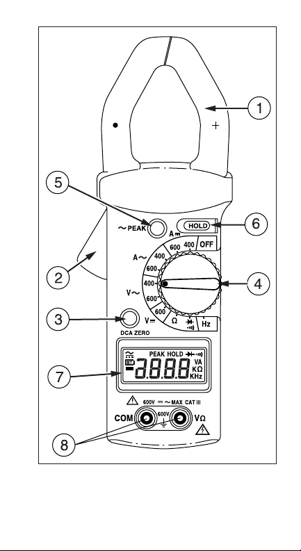
Instrument Familiarization (See inside front cover)
Transformer Jaws: Designed to pick up the current flowing
through the conductor.
Jaw Opening Lever: Press lever to open transformer jaws.
Release pressure to close the jaws.
Digital Display: 3-3/4 digit LCD (max. reading 3999), with
decimal point, AC/DC, polarity, unit and low battery (
indicators.
Function/Range Selector: Selects the desired function and range.
Changing position turns instrument back on after Auto-OFF.
BT
)
2
Page 7

Peak Hold Button: Toggles on and off. Captures the maximum
peak value of a current or voltage surge (motor start-up). “PEAK”
is shown on LCD.
Data Hold Button: Toggles on and off. Holds reading for all
functions and ranges. Always release HOLD before taking a new
measurement. “HOLD” is shown on LCD.
DCA ZERO Button: Push this button to zero the display before
measuring DC current.
Input Terminals: Always connect black test lead (negative) to
black COM input jack and red test lead to red “VΩ” input jack for
voltage, frequency, resistance, continuity, and diode
measurements
Measuring Procedures
General
1. Make sure that the selected function and range are
suitable for the measurement to be taken.
2. If the measured current is higher than the selected range
for a longer period of time, overheating may occur,
compromising the safety and operation of inner circuits.
3. Do not measure currents on high voltage conductors
(> 600 V) to avoid risks of discharge and/or incorrect
readings.
4. When measuring current, make sure that the test leads are
removed from the meter terminals.
5. The most accurate current reading will be obtained by
placing the conductor in the center of the jaws (aligned
with the centering marks on the transformer jaws).
DC Current Measurement
1. Set the function/range selector to the appropriate A F
position (400 or 600 A).
2. Press the DCA ZERO button to make sure that the display
is zero-reading.
3. Open spring-loaded clamp by pressing the lever on left
side of meter.
4. Position clamp around one wire or conductor and release
the clamp lever. Make sure that the clamp is entirely
closed. The clamp must be positioned around only one
conductor. If it is placed around two or more current
carrying conductors, the reading is FALSE.
5. Read the displayed value. The direction of the current
corresponds to the indication of the pointer on the jaw.
Polarity inversion is indicated by a ’-‘ (minus) symbol on
the display.
3
Page 8

AC Current Measurement
1. Set the function/range selector to the appropriate A B
position (400 or 600 A).
2. Open spring-loaded clamp by pressing the lever on left
side of meter.
3. Position clamp around one wire or conductor and release
the clamp lever. Make sure that the clamp is entirely
closed. The clamp must be positioned around only one
conductor. If it is placed around two or more current
carrying conductors, the reading is FALSE.
4. Read the displayed value.
DC and AC Voltage Measurement
The maximum input voltage for DC or AC Volts is 600 Vrms. Do
not attempt to take any voltage measurement that exceeds
600 Vrms to avoid electrical shock hazard or damage to the
instrument.
1. Set the function/range selector to the appropriate V F
(600 V) or V B (400 or 600 V) position.
2. Connect the black test lead to the “COM” terminal and the
red test lead to the “VΩ’’ terminal. Connect probe tips to
the circuit and read the value.
Frequency Measurement
Note: Both ammeter and voltmeter can be used for frequency
measurement. The clamp-on Ammeter detects the frequency of
the current circulating in the cable or bus-bar under test (the
current must be greater than 1 A in the 400 A range and greater
than 15 A in the 600 A range). The Voltmeter detects the
frequency of the voltage applied to the leads.
1. In either set-up (current or voltage measurement), set the
function/range switch to the Hz position.
2. Read the frequency value on the display.
W
Warning
4
Page 9

Resistance Measurement
Before taking any in-circuit resistance measurement, remove
power from the circuit being tested and discharge all
capacitors.
1. Set the function/range selector to the 4 kΩ position.
2. Connect the black lead to the COM terminal and red lead to
the “VΩ” terminal.
3. Connect the test leads to the resistance or circuit to be
measured and read the value on the display.
Continuity Measurement
Before taking any in-circuit continuity measurement, remove
power from the circuit being tested and discharge all
capacitors.
1. Set the function/range selector to the R position.
2. Connect the black lead to the COM terminal and red lead to
the “VΩ” terminal.
3. Connect the test leads to the circuit to be tested.
Continuity (resistance ≤40 Ω) is indicated by a continuous
beep tone.
Diode Test
1. Set the function/range selector to the G position.
2. Connect the black lead to the COM terminal and red lead to
the “VΩ” terminal.
3. Connect the red test lead to the anode, and the black test
lead to the cathode of the diode to be tested.
4. Read the forward voltage value on the display (approx.
0.6 V for a silicon diode or 0.4 V for a germanium diode).
An open diode is indicated by “OL”.
5. Reverse test lead connections to the diode to perform a
reverse bias test. “OL” indicates a good diode.
Notes: “OL” for both reverse and forward bias tests indicates an
open diode. A low voltage reading for both bias tests indicates a
shorted diode. If the diode is shunted by a resistor of 1000 ohms
or less, it must be removed from the circuit before taking the
measurement. Bipolar transistor junctions may be tested in the
same manner described above as emitter-base and basecollector junctions are diode junctions.
Peak Hold Measurement
Proceed as for voltage or current measurement (AC or DC).
Before actually taking the measurement, press the PEAK button.
“PEAK” is shown on the display. After taking a measurement, the
displayed reading is the maximum peak value of a surge in the
voltage or current.
W Warning
Warning
W
5
Page 10

Data Hold
Proceed as for voltage or current measurement (AC or DC).
While taking a measurement, press the HOLD button. “HOLD” is
shown on the display and the current meter reading is
maintained, even after disconnecting the test leads from the
circuit or removing the conductor from the clamp. Press HOLD
again to deactivate before taking a new measurement.
Specifications
General Specifications
Display: 3-3/4 Digit LCD, max. reading of 3999. Function and
unit indication.
Overrange indication: “OL” indicated.
Polarity indication: automatic; positive implied; negative
indicated.
Zero adjustment: automatic for all functions and ranges except
DC current (Zero adjustment button).
Ranging: manual function and range selection with rotary
selector switch. Autoranging for frequency measurement.
Special functions: Data Hold, Peak Hold
Operating principle: dual slope integration
Sampling rate: 2 /sec, nominal.
Maximum voltage between any terminal and earth ground: 600 V
Low Battery Indication:
operating voltage.
Auto Power Off: Approx. 30 minutes after no function change.
Environmental Conditions
Operating temperature: 0 °C to +40 °C, <80 % R.H., non-
condensing
Storage temperature: -10 °C to +60 °C, <70 % R.H., battery
removed.
Power source: Single 9 V battery (NEDA 1604,1EC 6F22)
Battery life: Alkaline 200 hours.
Maximum jaw opening: 40 mm (1.57 inches)
Pollution degree: Level II
Altitude: < 2000 meters
Size (WxLxH): 76x228x39 mm (3”x9”x1.5”)
Weight: 465 gr (incl. battery)
Accessories: Test leads, battery, manual and carrying case.
BT
when battery voltage drops below
6
Page 11

P >
Safety: Meets EN61010-1 Cat III 600V. EN61010-2-03, UL3111-
1, CSA22.2, No 1010-1
EMC: Meets EN55011, EN61000-4-2,4
EMC: This product complies with requirements of the following
European Community Directives: 89/336/EEC (Electromagnetic
Compatibility) and 73/23/EEC (Low Voltage) as amended by
93/68/EEC (CE Marking). However, electrical noise or intense
electromagnetic fields in the vicinity of the equipment may
disturb the measurement circuit. Measuring instruments will also
respond to unwanted signals that may be present within the
measurement circuit. Users should exercise care and take
appropriate precautions to avoid misleading results when making
measurements in the presence of electronic interference.
Electrical Specifications
Accuracy is ± (%reading + nbr digits) at 23 °C ± 5 °C, < 80 %
R.H. The current error is specified within the largest circle that
can be drawn inside the jaw.
DC Current
Range Resolution Accuracy Overload Prot.
400 A 0.1 A ± (2 %rdg + 5 dgt) 800 A
600 A 1 A ± (2 %rdg + 5 dgt) 800 A
AC Current, Trms
Range Resolution Accuracy Overload Freq.
Prot. Response
400 A 0.1 A ± (2 %rdg + 5 dgt) 800 A 40-450 Hz
600 A 1 A ± (2 %rdg + 5 dgt) 800 A 40-450 Hz
Conversion: Ac coupled Trms
Crest Factor (Non-Sinusoidal) (50 – 60 Hz)
1 – 3: ± 0.5 % 3 – 5: ± 3 % 5 – 7: ± 6 %
DC Voltage
Range Resolution Accuracy Input. Overload
Imped. Prot.
600 V 1 V ± (0.75 %rdg + 2 dgt) 1 MΩ 660 Vrms
AC Voltage Trms – Frequency response: 40-450 Hz
Range Resolution Accuracy Input Overload
Imped. Prot.
400 V 0.1 V ± (1.2 %rdg + 10 dgt) 1 MΩ 660 Vrms
600 V 1 V ± (1.2 %rdg + 10 dgt) 1 MΩ 660 Vrms
Conversion: Ac coupled Trms
Crest Factor (Non-Sinusoidal) (50 – 60 Hz)
1 – 3: ± 0.5 % 3 – 5: ± 3 % 5 – 7: ± 6 %
Frequency (Hz) – Autoranging for current and voltage
Range Resolution Accuracy Sensitivity Overload
Prot.
7
Page 12

4k Hz 1 Hz ± (0.5 %rdg + 5 dgt) 1 V / 5 A 660 Vrms
/800 A
20 kHz* 0.01 Hz ± (0.5 %rdg + 5 dgt) 5 V 660 Vrms
* - Voltage input only
Resistance
Range Resolution Accuracy Open Overload
circ.volts Prot.
4 kΩ 1 Ω± (1 %rdg + 5 dgt) ≤ 0.5 VDC 660 Vrms
Diode Test
Range Resolution Accuracy Open Overload
circ.volts Prot.
G 0.001 V ± (1 %rdg + 2 dgt) 3.0 VDC max 660 Vrms
Max short circuit current: 0.8 mA (typical)
Audible Continuity Test
Range Accuracy Open circ.volts Overload Prot.
40 Ω ≤ 0.5 V 3.0 VDC max 660 Vrms
Max short circuit current: 0.8 mA (typical)
Peak Hold Measurement, AC Voltage (50 Hz – 60 Hz)
Range Resolution Accuracy Input Overload
Imped. Prot.
400 V 0.1 V ± (1.5 %rdg +10 dgt) 1 MΩ 660 Vrms
600 V 1 V ± (1.5 %rdg +10 dgt) 1 MΩ 660 Vrms
Peak Hold Measurement, AC Current (50 Hz – 60 Hz)
Range Resolution Accuracy Overload
Prot.
400 A 0.1 A ± (2 %rdg +10 dgt) 800 A
600 A 1 A ± (2 %rdg +10 dgt) 800 A
Troubleshooting
In case of malfunction during the operation of the meter, the
following steps should be performed in order to isolate the cause
of the problem:
1. Check the battery.
2. Review the operating instructions for possible mistakes in
operating procedure.
3. Check the clamp against a known current source. Use the
voltage function to measure a known voltage (AC and DC).
4. Check the test leads for continuity (voltage and
resistance). Except for the replacement of the battery,
repair of the clamp should be performed only by a Factory
Authorized Service Center or by other qualified instrument
service personnel. Front panel and case can be cleaned
with a mild solution of detergent and water. Apply
sparingly with a soft cloth and let dry completely before
using. Do not use aromatic hydrocarbons or chlorinated
solvents for cleaning.
8
Page 13

Battery Replacement
To avoid electrical, shock remove the test leads from both the
meter and the test circuit before accessing the battery.
1. Replace the battery as soon as the low-battery symbol
BT
is displayed.
2. Set the function/range switch to OFF and remove the test
leads.
3. Position the meter face down. Remove the screw and lift
off the back cover.
4. Replace the battery with an equivalent 9 V battery.
5. Reassemble the instrument.
XWWARNING
9
Page 14

Repair
All test tools returned for warranty or non-warranty repair or for
calibration should be accompanied by the following: your name,
company’s name, address, telephone number, and proof of
purchase. Additionally, please include a brief description of the
problem or the service requested and include the test leads with
the meter. Non-warranty repair or replacement charges should
be remitted in the form of a check, a money order, credit card
with expiration date, or a purchase order made payable to
®
Test Tools.
Amprobe
In-Warranty Repairs and Replacement – All Countries
Please read the warranty statement and check your battery
before requesting repair. During the warranty period any
defective test tool can be returned to your Amprobe
distributor for an exchange for the same or like product. Please
check the “Where to Buy” section on www.amprobe.com for a
list of distributors near you. Additionally, in the United States and
Canada In-Warranty repair and replacement units can also be
sent to a Amprobe
address).
Non-Warranty Repairs and Replacement – US and Canada
Non-warranty repairs in the United States and Canada should be
sent to a Amprobe
Test Tools or inquire at your point of purchase for current repair
and replacement rates.
In USA In Canada
Amprobe
Everett, WA 98203 Mississauga, ON L4Z 1X9
Tel: 888-993-5853 Tel: 905-890-7600
Fax: 425-446-6390 Fax: 905-890-6866
Non-Warranty Repairs and Replacement – Europe
European non-warranty units can be replaced by your Amprobe
Test Tools distributor for a nominal charge. Please check the
“Where to Buy” section on www.amprobe.com for a list of
distributors near you.
European Correspondence Address*
Amprobe
P.O. Box 1186
5602 BD Eindhoven
The Netherlands
*(Correspondence only – no repair or replacement available from
this address. European customers please contact your
distributor.)
®
Test Tools Service Center (see below for
®
Test Tools Service Center. Call Amprobe®
®
Test Tools Amprobe® Test Tools
®
Test Tools Europe
®
Test Tools
®
10
Page 15

AC68C
True RMS AC/DC Clamp
Multimeter
Users Manual
• Mode d’emploi
• Bedienungshandbuch
• Manual de Uso
French
Françias
Page 16

Limites de garantie et de responsabilité
Amprobe® garantit l’absence de vices de matériaux et de
fabrication de ce produit dans des conditions normales
d’utilisation et d’entretien pendant une période d’un an prenant
effet à la date d’achat. Cette garantie ne s’applique pas aux
fusibles, aux piles jetables ni à tout produit mal utilisé, modifié,
contaminé, négligé ou endommagé par accident ou soumis à des
conditions anormales d’utilisation et de manipulation. Les
distributeurs agréés par Amprobe
appliquer une garantie plus étendue au nom de Amprobe®. Pour
bénéficier de la garantie, renvoyez le produit accompagné d’un
justificatif d’achat auprès d’un centre de services agréé par
Test ou du distributeur ou du revendeur Amprobe®.
Amprobe
®
Voir la section Réparation ci-dessus pour tous les détails. LA
PRESENTE GARANTIE EST LE SEUL ET EXCLUSIF RECOURS
TOUTES AUTRES GARANTIES, EXPLICITES, IMPLICITES OU
STATUTAIRES, NOTAMMENT LE CAS ECHEANT LES
GARANTIES DE QUALITE MARCHANDE OU D’ADAPTATION A
UN OBJECTIF PARTICULIER SONT EXCLUES PAR LES
PRESENTES. LE FABRICANT NE SERA EN AUCUN CAS TENU
RESPONSABLE DE DOMMAGES PARTICULIERS, INDIRECTS,
ACCIDENTELS OU CONSECUTIFS, NI D’AUCUNS DEGATS OU
PERTES DE DONNEES, SUR UNE BASE CONTRACTUELLE,
EXTRA-CONTRACTUELLE OU AUTRE. Etant donné que certains
pays ou états n’admettent pas les limitations d’une condition de
garantie implicite, ou l’exclusion ou la limitation de dégâts
accidentels ou consécutifs, les limitations et les exclusions de
cette garantie ne s’appliquent pas obligatoirement à chaque
acheteur.
ne sont pas autorisés à
®
Page 17

True RMS AC/DC Clamp Multimeter
Contenu
Symboles utilisés dans ce mode d’emploi................................... 1
Introduction.................................................................................1
Informations de sécurité.............................................................. 2
Désemballage ..............................................................................2
Présentation de l’appareil ............................................................3
Procédures de Mesure................................................................. 3
Spécifications ..............................................................................6
Dépannage................................................................................... 9
Remplacement de la Pile .............................................................9
Réparation .................................................................................10
Symboles utilisés dans ce mode d’emploi
Se reporter au mode
W
d’emploi
Double isolation
T
Courant continu
F
Courant alternatif
B
Conforme aux
P
directives de l’UE
Introduction
L'AC68C est une pince ampèremétrique numérique de mesure
efficace vraie (TRMS) qui mesure le courant c.a. et c.a. ainsi que
la tension c.a. et c.c., la résistance, la fréquence, la continuité et
le contrôle de diode.
Tension
X
dangereuse
BT
Pile
J Prise de terre
R Signal sonore
Underwriters
>
Laboratories,
Inc.
1
Page 18

Informations de sécurité
Le multimètres-pince Modèle AC68C est conformes à la norme
EN61010-1, CAT III 600 V, classe 2 et degré de pollution 2;
UL3111-1. Ils sont recommandés pour les appareils, les
équipements portables et la distribution d’énergie au niveau
local, etc., où seules de petites surtensions transitoires sont
possibles; il n’est pas destiné aux lignes du réseau d’alimentation
électrique principale aux lignes aériennes ou aux systèmes
câblés.
• Ne pas dépasser les limites de surcharge maximum par
fonction (voir les caractéristiques techniques) ou les
limites indiquées sur l’appareil lui-même. Ne jamais
appliquer plus de 600 V c.c./ V c.a. eff. entre le cordon de
test et la prise de terre.
• Inspecter le multimètre numérique, les cordons de test et
les accessoires avant toute utilisation. Ne pas utiliser de
pièce endommagée.
• Ne jamais se relier à la terre en prenant des mesures. Ne
toucher ni aux éléments de circuit exposés ni aux pointes
des sondes de test.
• Ne pas utiliser l’appareil dans une atmosphère explosive.
• Faire preuve d’extrême prudence en : mesurant une tension
>20 V // un courant >10 mA // les lignes d’alimentation
secteur avec charges inductives // les lignes d’alimentation
secteur pendant les orages électriques // un courant alors
que le fusible a sauté dans un circuit avec une tension en
circuit ouvert >600 V // lors d’une intervention sur un
appareil à écran cathodique.
• Toujours mesurer le courant en série avec la charge –
JAMAIS AUX BORNES d’une source de tension. Vérifier
d’abord le fusible. Ne jamais installer un fusible de calibre
différent.
• Retirer les cordons de test avant d’ouvrir le boîtier.
Désemballage
Votre emballage devrait contenir:
Un multimètre-pince.......................................................... 1
Une sacoche ......................................................................1
Une paire de cordons de test (un noir, un rouge).............. 1
Une pile 9 V (dans l’appareil).............................................1
Manuel...............................................................................1
Si une pièce manque ou est endommagée, retournez à votre
point de vente pour un échange.
2
Page 19

Présentation de l’appareil
1. Pince: Capte le courant qui passe par le conducteur.
2. Levier de la Pince: Poussez ce levier pour ouvrir la pince.
La pince ferme quand la pression est relachée.
3. Affichage Digital: LCD 3-3/4 digits (3999 points), point
décimal , indicateurs CA/CC, de polarité, d’unités et de pile
déchargée (
4. Sélecteur de fonctions et de gammes. Un changement de
position rallume également l’appareil après une cupure
automatique.
5. Mémoire de valeurs-crête: Enregistre la valeur-crête du
courant ou de la tension (ex.: mise en route d’un moteur).
“PEAK” est affiché.
6. Maintien de lecture: Maintient la lecture pour toutes
fonctions et gammes. “HOLD” est affiché. Désactivez
HOLD pour prendre de nouvelles mesures.
7. Mise à Zéro pour mesures de courant continu: Pressez ce
bouton avant de prendre une mesure de courant continu.
8. Entrées: Pour les mesures de tension, de résistance, de
continuité, de fréquence et de diodes, connectez toujours
le cordon de mesure noir à l’entrée COM, et le rouge à
l’entrée VΩ.
BT
).
Procédures de Mesure
Général
1. Assurez-vous que la fonction et la gamme choisies
correspondent à la mesure que vous voulez effectuer.
2. Si le courant mesuré dépasse la gamme choisie durant
une période de temps prolongée, un surchauffement peut
se produire, compromettant la sécurité et le bon
fonctionnement des circuits internes.
3. Ne mesurez pas du courant sur des conducteurs à haute
tension (> 600 V) afin d’éviter des chocs électriques et/ou
des mesure incorrectes.
4. Quand vous mesurez du courant, assurez-vous que les
cordons de mesure sont retirés de l’appareil.
5. La meilleure précision de mesure est obtenue quand le
conducteur de courant est placé au milieu de de la pince
(dans l’alignement des marquages sur la pince).
3
Page 20

Mesure de Courant Continu
1. Placez le sélecteur sur la position A F désirée (400 ou
600 A).
2. Pressez le bouton de mise-à-zéro et assurez-vous que
l’afficheur est bien bien mis à zéro.
3. Ouvrez la pince en poussant sur le levier.
4. Placez la pince autour du conducteur et fermez la (en
relachant le levier). Assurez-vous que la pince est
complètement fermée et qu’elle ne contient qu’un seul
conducteur. Si elle en contient plusieurs, la mesure est
faussée.
5. Lisez la valeur affichée. La direction du courant
correspond au marquage sur la pince. Une inversion de
polarité est indiquée par un symbole −(moins) sur
l’afficheur.
Mesure de Courant Alternatif
1. Placez le sélecteur sur la position A B désirée (400 ou
600 A).
2. Ouvrez la pince en poussant sur le levier.
3. Placez la pince autour du conducteur et fermez la (en
relachant le levier). Assurez-vous que la pince est
complètement fermée et qu’elle ne contient qu’un seul
conducteur. Si elle en contient plusieurs, la mesure est
faussée.
4. Lisez la valeur affichée.
Mesure de Tension Continue et Alernative
La valeur d’entrée maximale pour la mesure de tension
continue ou alterntive est de 600Veff. Ne mesurez pas une
tension supérieure afin d’éviter des chocs électriques et/ou
des dommages à l’appareil.
1. Placez le sélecteur sur la fonction et gamme appropriées:
V F (600 V) ou V B(400 ou 600 V).
2. Connectez le cordon noir à l’entrée COM et le rouge à
l’entrée VΩ. Connectez les pointes de touche au circuit (en
parallèle avec la source de tension) et lisez la valeur.
W Avertissement
4
Page 21

Mesure de Fréquence
Note: L’ampèremètre et le voltmètre peuvent être utilisés pour la
mesure de la fréquence. La pince détecte la fréquence du courant
qui circule dans le conducteur ( le courant doît être supérieur à
1 A pour la gamme de 400 A et supérieur à 15 A pour la gamme
de 600 A). Le voltmètre détecte la fréquence de la tension
appliquée.
1. Pour les deux modes de mesure, placez le sélecteur sur la
position Hz.
2. Lisez la fréquence sur l’afficheur.
Mesure de Résistance
Avant chaque mesure en-circuit, coupez l’alimentation et
déchargez les condensateurs.
1. Placez le sélecteur sur la position 4 KΩ.
2. Connectez le cordon noir à l’entrée COM et le rouge à
l’entrée VΩ.
3. Connectez les cordons à la résistance ou au circuit à
mesurer et lisez la valeur sur l’afficheur.
Mesure de Continuité
Avant chaque mesure en-circuit, coupez l’alimentation et
déchargez les condensateurs.
1. Placez le sélecteur sur la position R.
2. Connectez le cordon noir à l’entrée COM et le rouge à
l’entrée VΩ.
3. Connectez les cordons au circuit à mesurer. Une
continuité (résistance ≤40 Ω) est indiqué par un singnal
sonore continu.
Test de Diodes et de Transistors
1. Placez le sélecteur sur G.
2. Connectez les cordon rouge à l’entrée VΩ et le noir à
l’entrée COM.
3. Connectez les pointes de touche à la diode – le rouge à
l’anode, le noir à la cathode.
4. Lisez la chute de tension en direction passante (environ
0.6 V pour une diode au Si; 0.4 V pour une diode au Ge).
Une diode ouverte est affichée par “OL”.
5. Inversez la connection pour mesurer en direction de
bloquage. Une bonne diode est affichée par “OL”.
Notes: “OL” dans les deux directions indique une diode ouverte;
une lecture basse indique une diode court-circuitée. Les
jonctions de transistors peuvent être testées comme des diodes.
Mémoire Crête (Peak Hold)
Suivez la procédure de mesure pour le courant ou la tension (cc
ou ca). Avant de prendre la mesure, pressez la bouton PEAK.
W Avertissement
W Avertissement
5
Page 22

“PEAK” apparait sur l’afficheur. L’afficheur maintient la valeur
crête maximale mesurée.
Maintien de Lecture (Probe Hold)
Probe Hold maintient l’affichage pour lecture ultérieure (même
quand les pointes de touche sont séparées du circuit). Activez
HOLD avant la mesure. Pressez HOLD à nouveau (désactiver)
avant de prendre une nouvelle mesure.
Spécifications
Spécifications Générales
Afficheur: LCD à 3-3/4 digits, 3999 points. Indicateurs de
fonctions et d’unités.
Indication de Dépassement de Calibre: “OL”.
Indication de polarité: automatique; positive sousentendue;
négative affichée.
Mise à zéro de l’afficheur: automatique pour toutes fonctions et
gammes, sauf courant continu (bouton de mise à zéro).
Changement de gammes: avec sélecteur rotatif. Automatique
pour la fréquence.
Fonctions spéciales: Maintien de lecture; mémoire crête
Principe de fonctionnement: intégration à double rampe
Taux de mesure: 2 /sec, nominal.
Tension max entre une entrée et la terre: 600 V
Indication de pile déchargée:
immédiatement.
Coupure automatique: Après environ 30 minutes d’inactivité.
Conditions d’Environnement
Température d’Utilisation: 0 °C à +40 °C, <80 % H.R. Sans
condensation.
Température de Stockage: -10 °C à + 60 °C, <70 % H.R. pile
enlevée.
Alimentation: Pile 9 V (NEDA 1604,1EC 6F22)
Autonomie: Alkaline 200 heures.
Ouverture max. de la Pince: 40 mm
Degré de Pollution: Niveau II
Altitude : < 2000 m (6561,7 pieds)
Dimensions (PxLxH): 76x228x39 mm
Poids: 465 g (avec pile)
Accessoires: Cordons de test, pile, manuel et sacoche
BT
Remplacez la pile
P >
Sécurité: Conforme à EN61010-1 Cat. III 600V, EN61010-2-03,
UL3111-1,CSA22.2, No 1010-1
EMC: selon EN55011, EN61000-4-2,4
EMC: Ce produit est conforme aux exigences des directives
suivantes de la Communauté Euripéenne: 89/336/EEC
(Compatibilité Electronmagnétique) et 73/23/EEC (Basse
Tension), modifiée par 93/68/EEC (CE Marking). Cependant, du
6
Page 23

bruit électrique ou des champs électromagnétiques intenses
dans la proximité de l’instrument peuvent influencer le circuit de
mesure. L’instrument peut également être perturbé par des
signaux parasytes dans le circuit mesuré. L’utilisateur doit être
vigilant et prendre des précautions appropriées pour éviter des
résultats erronés quand les mesures sont prises en présence
d’interférences électromagnétiques.
Spécifications Electriques
La précison est ±(%lecture + nbr digits) à 23 °C ± 5 °C, < 80 %
H.R. La précision pour le courant est donnée pour le plus grand
cercle qui peut être inscrit dans la pince.
Courant Continu
Gamme Résolution Précision Prot. de surcharge
400 A 0.1 A ± (2 %lect + 5 dgt) 800 A
600 A 1 A ± (2 %lect + 5 dgt) 800 A
Courant Alternatif
Gamme Résolution Précision Prot. Gamme
Surcharge Fréq.
400 A 0.1 A ± (2 %lect + 5 dgt) 800 A 40-450 Hz
600 A 1 A ± (2 %lect + 5 dgt) 800 A 40-450 Hz
Conversion : Couplage alternatif Trms
Facteur de crête (non-sinusoïdal) (50 – 60 Hz)
1 – 3: ± 0.5 % 3 – 5: ± 3 % 5 – 7: ± 6 %
Tension Continue
Gamme Résolution Précision Imp. Prot. de
entrée surcharge
600 V 1 V ± (0.75 %lect + 2 dgt) 1 MΩ 660 Vrms
Tension Alternative TRMS
Gamme Résolution Précision Imp. Prot. de
entrée surcharge
400 V 0.1 V ± (1.2 %lect + 5 dgt) 1 MΩ 660 Vrms
600 V 1 V ± (1.2 %lect + 5 dgt) 1 MΩ 660 Vrms
Conversion : Couplage alternatif Trms
Facteur de crête (non-sinusoïdal) (50 – 60 Hz)
1 – 3: ± 0.5 % 3 – 5: ± 3 % 5 – 7: ± 6 %
Fréquence (Hz) – courant et tension
Gamme Résolution Précision Sensibilité Prot. de
surcharge
4 kHz 1 Hz ± (0.5 %lect + 5 dgt) 1 V/ 5 A 660 Vrms
/800 A
20 kHz * 0.01 Hz ± (0.5 %lect + 5 dgt) 5 V 660 Vrms
* - Tension d'entrée uniquement
Résistance
Gamme Résolution Précision Tens.Circ. Prot.
– Gamme de fréquence: 40-450 Hz
7
Page 24

Ouv. surcharge
4 kΩ 1 Ω ± (1 %lect + 5 dgt) 0.5 VDC 660 Vrms
Test de Diodes
Gamme Résolution Précision Tens.Circ. Prot.
Ouv. surcharge
G 0.001 V ± (1 %lect + 2 dgt) 3.0 VDC max 660 Vrms
Courant en court-circuit max: 0.8 mA (typique)
Test de Continuité avec Indication Sonore
Gamme Précision Tens.Circ.Ouv. Prot.surcharge
40 Ω ≤ 0.5 V 3.0 VDC max 660 Vrms
Courant en court-circuit max: 0.8 mA (typique)
Mesure de Valeur Crête, Tension Alternative (50 Hz – 60 Hz)
Gamme Résolution Précision Imp. Prot.
entrée surcharge
400 V 0.1 V ± (1.5 %lect +10 dgt) 1 MΩ 660 Vrms
600 V 1 V ± (1.5 %lect +10 dgt) 1 MΩ 660 Vrms
Mesure de Valeur Crête, Courant Alternatif (50 Hz – 60 Hz)
Gamme Résolution Précision Prot.
surcharge
400 A 0.1 A ± (2 %lect +10 dgt) 800 A
600 A 1 A ± (2 %lect +10 dgt) 800 A
8
Page 25

Dépannage
En cas de problèmes:
1. Vérifiez le chargement de la pile.
2. Vérifiez le mode d’emploi.
3. Mesurez une valeur de courant connue. Mesurez une
tension connue.
4. Vérifiez les câbles de mesure (tension et résistance).
A part le remplacement de la pile, toute réparation ne doit être
effectuée que par un centre de services agréé par Amprobe
Le boîtier peut être nettoyé avec une savonnée douce. Laissez
secher complètement avant utilisation.
Remplacement de la Pile
Pour éviter les chocs électriques, retirer les cordons de test du
multimètre et du circuit de test avant d’accéder à la pile.
L’instrument est alimenté par une pile 9 V. Remplacez la pile
BT
dès que
1. Coupez l’alimentation de l’appareil en enlevez les cordons
de mesure.
2. Dévissez et enlevez le boîtier arrière.
3. Remplacez la pile et réassemblez le boîtier.
XWAvertissement
est affiché.
.
®
9
Page 26

Réparation
Tous les outils de test renvoyés pour un étalonnage ou une
réparation couverte ou non par la garantie doivent être
accompagnés des éléments suivants : nom, raison sociale,
adresse, numéro de téléphone et justificatif d'achat. Ajoutez
également une brève description du problème ou du service
demandé et incluez les cordons de test avec le multimètre. Les
frais de remplacement ou de réparation hors garantie doivent
être acquittés par chèque, mandat, carte de crédit avec date
d'expiration ou par bon de commande payable à l'ordre de
®
Test Tools.
Amprobe
Remplacements et réparations sous garantie – Tous pays
Veuillez lire la déclaration de garantie, et vérifier la pile avant de
demander une réparation. Pendant la période de garantie, tout
outil de test défectueux peut être renvoyé auprès de votre
distributeur Amprobe
produit identique ou similaire. Consultez la section “Where to
Buy” sur le site www.amprobe.com
distributeurs dans votre région. Au Canada et aux Etats-Unis, les
appareils devant être remplacé ou réparé sous garantie peuvent
également être envoyés dans un centre de services Amprobe
Test Tools (voir les adresses ci-dessous).
Remplacements et réparations hors garantie – Canada et EtatsUnis
Les appareils à réparer hors garantie au Canada et aux Etats-Unis
doivent être envoyés dans un centre de services Amprobe® Test
Tools. Appelez Amprobe® Test Tools ou renseignez-vous auprès
de votre lieu d’achat pour connaître les tarifs en vigueur pour le
remplacement ou les réparations.
Aux Etats-Unis Au Canada
®
Test Tools Amprobe® Test Tools
Amprobe
Everett, WA 98203 Mississauga, Ontario L4Z 1X9
Tél. : 888-993-5853 Tél. : 905-890-7600
Fax : 425-446-6390 Fax : 905-890-6866
Remplacements et réparations hors garantie – Europe
Les appareils européens non couverts par la garantie peuvent
être remplacés par votre distributeur Amprobe® Test Tools pour
une somme nominale. Consultez la section “Where to Buy” sur le
site www.amprobe.com
dans votre région.
Adresse postale européenne*
Amprobe
P.O. Box 1186
5602 B.D. Eindhoven
Pays-Bas
*(Réservée à la correspondance – Aucun remplacement ou
réparation n’est possible à cette adresse. Nos clients européens
doivent contacter leur distributeur.)
®
Test Tools pour être échangé contre un
pour obtenir la liste des
pour obtenir la liste des distributeurs
®
Test Tools Europe
®
10
Page 27

AC68C
True RMS AC/DC Clamp
Multimeter
Users Manual
• Mode d’emploi
• Bedienungshandbuch
• Manual de Uso
Deutsch
German
Page 28

Beschränkte Gewährleistung und
Haftungsbeschränkung
Es wird gewährleistet, dass dieses Amprobe®-Produkt für die
Dauer von einem Jahr ab dem Kaufdatum frei von Material- und
Fertigungsdefekten ist. Diese Gewährleistung erstreckt sich nicht
auf Sicherungen, Einwegbatterien oder Schäden durch Unfälle,
Nachlässigkeit, Missbrauch, Änderungen oder abnormale
Betriebsbedingungen bzw. unsachgemäße Handhabung. Die
Verkaufsstellen sind nicht dazu berechtigt, diese Gewährleistung
im Namen von Amprobe
Gewährleistungsperiode Serviceleistungen zu beanspruchen, das
Produkt mit Kaufnachweis an ein autorisiertes Amprobe
Tools Service-Center oder an einen Amprobe®-Fachhändler/Distributor einsenden. Einzelheiten siehe Abschnitt „Reparatur“
oben. DIESE GEWÄHRLEISTUNG STELLT DEN EINZIGEN UND
ALLEINIGEN RECHTSANSPRUCH AUF SCHADENERSATZ DAR.
ALLE ANDEREN GEWÄHRLEISTUNGEN - VERTRAGLICH
GEREGELTE ODER GESETZLICHE VORGESCHRIEBENE EINSCHLIESSLICH DER GESETZLICHEN GEWÄHRLEISTUNG
DER MARKTFÄHIGKEIT UND DER EIGNUNG FÜR EINEN
BESTIMMTEN ZWECK, WERDEN ABGELEHNT DER
HERSTELLER ÜBERNIMMT KEINE HAFTUNG FÜR SPEZIELLE,
INDIREKTE, NEBEN- ODER FOLGESCHÄDEN ODER VERLUSTE,
DIE AUF BELIEBIGER URSACHE ODER RECHTSTHEORIE
BERUHEN. Weil einige Staaten oder Länder den Ausschluss oder
die Einschränkung einer implizierten Gewährleistung sowie von
Begleit- oder Folgeschäden nicht zulassen, ist diese
Gewährleistungsbeschränkung möglicherweise für Sie nicht
gültig.
zu erweitern. Um während der
®
Test
®
Page 29

True RMS AC/DC Clamp Multimeter
Inhalt
Symbole in diesem Handbuch .....................................................1
Einleitung..................................................................................... 1
Sicherheitsinformationen............................................................. 2
Lieferumfang ...............................................................................2
Vorstellung des Gerätes............................................................... 3
Meßprozeduren............................................................................ 3
Spezifikationen ............................................................................6
Fehlersuche .................................................................................9
Batteriewechsel............................................................................9
Reparatur................................................................................... 10
Symbole in diesem Handbuch
W Im Handbuch nachlesen X Gefährliche Spannung
T Schutzisoliert
F Gleichstrom J Erde, Masse
B Wechselstrom R Akustischer Alarm
Übereinstimmung mit
P
EU-Richtlinien
Einleitung
Das AC68C ist ein digitales Echteffektivwert-Zangenmessgerät,
das Wechsel- und Gleichstromstärke, Wechsel- und
Gleichspannung, Widerstand, Frequenz und Kontinuität misst
und Diodenprüfung durchführ.
BT
Batterie
>
Underwriters
Laboratories, Inc.
1
Page 30

Sicherheitsinformationen
Die Zangenmultimeter AC68C ist mit: EN61010-2-032, EN610101, CAT- III 600 V, Klasse 2 und Verschmutzungsgrad 2; UL3111-
1. Anwendung ist empfohlen für lokale Stromverteilung,
Haushaltsgeräte, tragbare Geräte usw., bei denen nur kleinere
Spannungsspitzen auftreten können; Anwendung wird nicht
empfohlen für primäre Stromverteilung,
Hochspannungsleitungen und Kabelsysteme.
• Die maximalen Überlastungsgrenzen der einzelnen
Funktionen (siehe Technische Daten) und die auf dem
Instrument markierten Grenzwerte nicht überschreiten.
Zwischen Messleitung und Masse niemals mehr als 1000 V
Gleichspannung/750 V Wechselspannung eff. anlegen.
• Vor jedem Gebrauch das DMM, die Messleitungen und das
Zubehör prüfen. Keine beschädigten Teile verwenden.
• Sich selbst isolieren, wenn Messungen durchgeführt
werden. Keine freiliegenden Schaltungselemente oder
Prüfspitzen/Messleitungen berühren.
• Das Messgerät nicht in Umgebungen mit explosiven Gasen
betreiben.
• In den folgenden Situationen außerordentlich große
Vorsicht walten lassen: Messung von Spannung >20 V //
Stromstärke >10 mA // Wechselspannungslei- tungen mit
Induktivlasten // Wechselspannungsleitungen während
Gewittern // Strom mit einer durchgebrannten Sicherung in
einem Schaltkreis mit Leerlaufspannung >600 V // bei der
Wartung von Kathodenröhrengeräten.
• Strommessung immer in Serie mit der Last - NIEMALS über
eine Spannungsquelle. Zuerst die Sicherung prüfen.
Niemals eine Sicherung durch eine Sicherung anderer
Nennlast ersetzen.
• Vor Öffnen des Gehäuses die Messleitungen entfernen.
Lieferumfang
Die Verpackung sollte enthalten:
Ein digitales Zangenmultimeter 1
Eine Tragetasche 1
Ein Paar Meßkabel (ein schwarz, ein rot) 1
Eine 9 V Batterie (im Gerät) 1
Und diese Anleitung 1
Sollte ein Teil beschädigt sein oder fehlen, kehren Sie bitte zur
Verkaufsstelle zurück für einen Umtausch.
2
Page 31

Vorstellung des Gerätes
1. Stromzange: Überträgt den Strom der durch den Leiter
fließt.
2. Zangenhebel: Hebel drücken um Zange zu öffnen. Zange
schließt beim Loslassen des Hebels.
3. Digitale Anzeige: 3-3/4-stelliges LCD (max. Ablesung
3999), Dezimalpunkt, AC/DC, Polaritäts-, Einheits- und
entladene (
4. Funktionsschalter: Wählt die gewünschte Funktion und
Bereich. Positionswechsel schaltet das Gerät nach
automatischer Abschaltung wieder ein.
5. Spitzenwertspeichertaste: Speichert den maximalen
Spitzenwert von Strom oder Spannung.
(Motoreneinschaltung). “PEAK” wird angezeigt.
6. Data Hold Taste: Friert die Anzeige für alle Bereiche und
Funktionen. HOLD erneut drücken (lösen) bevor Sie eine
neue Messung vornehmen.
7. Nullabgleichtaste für Gleichstrommessung: Diese Taste
drücken bevor Sie eine Gleichstrommessung vornehmen.
8. Eingänge: Für Spannungs-, Widerstands-, Durchgangs-
und Dioden-messungen, das schwarze Meßkabel immer
mit COM Eingang und rotes immer mit VΩ Eingang
verbinden.
BT
) Batterie Anzeigen.
Meßprozeduren
Allgemein
1. Stellen Sie sicher daß gewählte Funktion und Bereich mit
der vorzunehmenden Messung übereinstimmen.
2. Wenn der gemessene Strom den gewählten Bereich
längere Zeit überschreitet, kann Überhitzung auftreten
welche die Sicherheit und Funktion der inneren
Schaltkreise gefährdet. Messen Sie keinen Strom an
Hochspannungskabeln (> 600 V) um elektrische Schläge
und/oder ungenaue Messungen zu vermeiden.
3. Wenn Sie Strommessungen vornehmen, stellen Sie sicher
daß die Meßkabel vom Gerät abgezogen sind.
4. Die größte Meßgenauigkeit wird erreicht, wenn der
Stromleiter in der Zangenmitte liegt (in Übereinstimmung
mit den Markierungen auf der Zange).
3
Page 32

Gleichstrommessung
1. Wahlschalter auf gewünschte A F Position stellen. (400
oder 600 A).
2. Nullabgleichtaste drücken und sicher stellen daß Anzeige
auf Null steht.
3. Zange durch Drücken des Hebels öffnen.
4. Zange um Stromkabel bringen und schließen (durch
Loslassen des Hebels). Stellen Sie sicher daß nur ein
Kabel in der Zange ist und daß die Zange gut geschlossen
ist. Bei mehreren Kabeln in der Zange währe die Messung
falsch.
5. Stromwert ablesen. Die Richtung des Stromes stimmt mit
der Markierung auf der Zange überein. Umgekehrte
Polarität wird mit einem Minus ( - ) Symbol auf der
Anzeige angezeigt.
Wechselstrommessung
1. Wahlschalter auf gewünschte A B Position (400 oder
600 A) stellen.
2. Zange durch Drücken des Hebels öffnen.
3. Zange um Stromkabel bringen und schließen (durch
Loslassen des Hebels). Stellen Sie sicher daß nur ein
Kabel in der Zange ist und daß die Zange gut geschlossen
ist. Bei mehreren Kabeln in der Zange währe die Messung
falsch.
4. Stromwert ablesen.
Gleich- und Wechselspannungsmessung
Die maximale Eingangsspannung für Gleich- und Wechselspannungsmessung ist 600 Vrms. Messen Sie keine höhere
Spannung um elektrische Schläge und/oder Zerstörung des
Gerätes zu vermeiden.
1. Wahlschalter auf gewünschte Funktion und Bereich stellen
V F (600 V) oder V B (400 oder 600 V).
2. Schwarzes Meßkabel mit COM und rotes mit VΩ
verbinden. Meßspitzen mit Schaltkreis verbinden (parallel
mit Spannungsquelle) und Meßwert ablesen.
W Warnung
4
Page 33

Frequenzmessung
Anmerkung: Sowohl Ammeter als Voltmeter können zur
Frequenzmessung verwendet werden. Die Stromzange bestimmt
die Frequenz des Stromes der durch die Zange fließt (der Strom
muß höher als 1 A im 400 A Bereich und höher als 15 A im
600 A Bereich sein). Das Voltmeter bestimmt die Frequenz der
anliegenden Spannung.
1. Für jede Meßart, FunktionsBereichsschalter auf Hz
Position stellen.
2. Frequenz ablesen.
Widerstandsmessung
For jeder Messung im Schaltkreis, Strom abschalten und
Kondensatoren entladen.
1. Funktionsschalter auf 4 KΩ Position stellen.
2. Schwarzes Meßkabel mit COM und rotes mit Ve
verbinden.
3. Meßkabel mit Widerstand oder Schaltkreis verbinden und
Meßwert ablesen.
Durchgangstest
For jeder Messung im Schaltkreis, Strom abschalten und
Kondensatoren entladen.
1. Funktionsschalter auf R Position stellen.
2. Schwarzes Meßkabel mit COM und rotes mit Ve
verbinden.
3. Meßkabel mit Schaltkreis verbinden. Durchgang
(Widerstand ≤40 Ω) wird mit einem Dauerton angezeigt.
Dioden- und Transistortest
1. Funktionsschalter auf G stellen.
2. Rotes Meßkabel mit Veingang und schwarzes mit COM
Eingang verbinden.
3. Meßkabel mit Diode verbinden – rotes mit Anode;
schwarzes mit Kathode.
4. Spannungsabfall in Durchlaßrichtung ablesen (ung. 0.6 V
für eine Silikon-Diode und 0.4 V für eine Germaniumdiode.
Eine offene Diode wird mit Überlast angezeigt).
5. Verbindung umdrehen um in Sperrrichtung zu messen.
Überlast zeigt eine gute Diode an.
Anmerkung: Überlast in beiden Richtungen zeigt eine offene
Diode an; eine niedrige Ablesung eine kurzgeschlossene Diode.
Transistorübergänge können wie Dioden getestet werden.
Spitzenwertspeicher
Prozedur für Spannungs- oder Strommessung folgen (AC oder
DC). Bevor Sie eine Messung vornehmen, PEAK Taste drücken.
“PEAK” wird angezeigt. Die Anzeige hält den maximal
gemessenen Spitzenwert fest.
W Warnung
W Warnung
5
Page 34

Anzeigesperre
Probe Hold erhält die Anzeige für spätere Ablesung (auch wenn
die Meßkabel vom Schaltkreis getrennt sind). HOLD vor der
Messung drücken. Hold erneut drücken (lösen), bevor Sie eine
neue Messung vornehmen.
Spezifikationen
Allgemeine Spezifikationen
Anzeige: 3-3/4-stelliges LCD, max Ablesung 3999. Funktions-
und Einheitsanzeigen
Überlastanzeige: “OL”.
Polaritätsanzeige: automatisch; positiv unterstellt; negativ
angezeigt.
Nullabgleich: automatisch für alle Funktionen und Bereiche, ausg.
Gleichstrom (Nullabgleichtaste).
Bereichswahl: Manuell mit Drehschalter. Automatisch bei
Frequenzmessung.
Spezielle Funktionen: Meßwertspeicher, Spitzenwertspeicher
Meßmethode: Doppelte Rampenintegration
Meßrate: 2 /Sek, nominal.
Maximale Spannung zwischen einem Eingang und Erde:
Entladene Batterieanzeige:
BT
Batterie sofort wechseln.
600V
Automatische Abschaltung: nach ungefähr 30 Minuten
Inaktivität.
Umgebungsbedingungen
Betriebstemperatur: 0 °C bis +40 °C, < 80 % R.F., nicht
kondensierend
Lagertemperatur: -10 °C bis +60 °C, < 70 % R.F., Batterie
entfernt.
Stromversorgung: 9 V Batterie (NEDA 1604,1EC 6F22).
Batterielebensdauer: Alkaline 200 Stunden.
Max. Zangenöffnung: 40 mm
Pollutionsgrad: Niveau II
Höhenlage: 2000 m (6561,7 Fuß)
Abmessungen (BxLxH): 76x228x39 mm
Gewicht: 465 g (mit Batterie)
Zubehör: Meßkabel, Batterie, Anleitung und Tragetasche.
6
Page 35

P >
Sicherheit: Gemäß EN61010-1 Cat. III 600V , EN61010-2-03.
UL3111-1, CSA22.2, No 1010-1
EMC: Gemäß EN55011,EN61000-4-2,4
EMC Dieses Produkt beantwortet an die Bestimmungen der
folgenden EWG Richtlinien: 89/336/EEC (Elektromagnetische
Kompatibilität) und 73/23/EEC (Niedrige Spannung) geändert
durch 93/68/EEC (CE Marking). Elektrisches Rauschen und
starke magnetische Felder in der direkten Umgebung des
Meßgerätes können jedoch den Meßkreis beeinflussen. Das Gerät
kann auch durch Störsignale im gemessenen Schaltkreis
beeinflußt werden. Der Anwender muß Vorsichtsmaßnahmen
treffen um irreführende Meßergebnisse bei Messungen in der
Umgebung von starken elektromagnetischen Feldern zu
vermeiden.
Elektrische Spezifikationen
Genauigkeit ist ± (%Ablesung + Anz. Digits) bei 23 °C ± 5 °C, <
80 % R.F. Die Stromgenauigkeit is spezifiziert im größten Kreis
der in die Zange paßt.
Gleichstrom
Bereich Auflösung Genauigkeit Überlastschutz
400 A 0.1 A ± (2 %vMW + 5 Dgt) 800 A
600 A 1 A ± (2 %vMW + 5 Dgt) 800 A
Wechselstrom
Bereich Auflösung Genauigkeit ÜberlastschutzFrequenzbereich
400 A 0.1 A ± (2 %vMW + 5 Dgt) 800 A 40-450 Hz
600 A 1 A ± (2 %vMW + 5 Dgt) 800 A 40-450 Hz
Konvertierung: Trms wechselstromgekoppelt
Spitzenfaktor (nicht sinusartig) (50 – 60 Hz)
1 – 3: ± 0.5 % 3 – 5: ± 3 % 5 – 7: ± 6 %
Gleichspannung
Bereich Auflösung Genauigkeit Eing. Überlastschutz
Imped.
600 V 1 V ± (0.75 %vMW + 2 Dgt) 1 MΩ 660 Vrms
Wechselspannung TRMS – Frequenzbereich: 40-450 Hz
Bereich Auflösung Genauigkeit Eing. Überlastschutz
Imped.
400 V 0.1 V ± (1.2 %vMW + 10 Dgt) 1 MΩ 660 Vrms
600 V 1 V ± (1.2 %vMW + 10 Dgt) 1 MΩ 660 Vrms
Konvertierung: Trms wechselstromgekoppelt
Spitzenfaktor (nicht sinusartig) (50 – 60 Hz)
1 – 3: ± 0.5 % 3 – 5: ± 3 % 5 – 7: ± 6 %
Frequenz (Hz) – Auto-Bereichswahl für Strom und Spannung
Bereich Auflösung Genauigkeit Empfindlichk.
Überlastschutz
4 kHz 1 Hz ± (0.5 %vMW + 5 Dgt) 1 V/5 A 660 Vrms/800 A
7
Page 36

20 kHz* 0.01 Hz ± (0.5 %vMW + 5 Dgt) 5 V 660 Vrms/800 A
* - nur Eingangsspannung
Widerstand
Bereich Auflösung Genauigkeit Leerlaufsp. Überlastschutz
4 kΩ 1 Ω ± (1 %vMW + 5 Dgt) 0.5 VDC 660 Vrms
Diodentest
Bereich Auflösung Genauigkeit Leerlaufsp. Überlastschutz
G 0.001 V ±( 1 %vMW + 2 Dgt) 3.0 VDC max 660 Vrms
Max Kurzschlußstrom: 0.8 mA (typisch)
Durchgangstest mit Summer
Bereich Auflösung Leerlaufsp. Überlastschutz
40 Ω ≤ 0.5 MW 3.0 VDC max 660 Vrms
Max Kurzschlußstrom: 0.8 mA (typisch)
Spitzenwertmessung, Wechselspannung (50 Hz – 60 Hz)
Bereich Auflösung Genauigkeit Eingangsimp. Überlastschutz
400 V 0.1 V ±(1.5 %vMW + 10 Dgt) 1 MΩ 660 Vrms
600 V 1 V ±(1.5 %vMW + 10 Dgt) 1 MΩ 660 Vrms
Spitzenwertmessung, Wechselstrom (50 Hz – 60 Hz)
Bereich Auflösung Genauigkeit Überlastschutz
Frequenzbereich
400 A 0.1 A ± (2 %vMW + 10 Dgt) 800 A 40-450 Hz
600 A 1 A ± (2 %vMW + 10 Dgt) 800 A 40-450 Hz
8
Page 37

Fehlersuche
Bei Problemen bitte folgendes prüfen:
1. Batterieladung.
2. Meßprozedur.
3. Einen bekannten Stromwert mit der Zange prüfen. Eine
bekannte Spannung messen.
4. Meßkabel prüfen (Spannungs-und Widerstandsmessung).
Mit Ausnahme des Batteriewechsels sollte jede Reparatur der
Stromzange nur durch eine Wavetek Amprobe
Servicestelle vorgenommen werden.
Das Gehäuse kann mit einer milden Seifenlösung gereinigt
werden. Vor Gebrauch gut trocknen lassen.
Batteriewechsel
Das Geräte wird durch eine 9V Batterie betrieben. Batterie
wechseln sobald
1. Gerät abschalten und Meßkabel entfernen.
2. Schraube von Rückseite entfernen und Geräterückseite
abheben.
3. Batterie ersetzen und Gerät wieder zusammensetzen.
BT
angezeigt wird.
-anerkannte
®
9
Page 38

Reparatur
Zu allen Geräten, die zur Reparatur oder Kalibrierung im Rahmen
der Garantie oder außerhalb der Garantie eingesendet werden,
muss folgendes beigelegt werden: Name des Kunden,
Firmenname, Adresse, Telefonnummer und Kaufbeleg. Zusätzlich
bitte eine kurze Beschreibung des Problems oder der
gewünschten Wartung sowie die Messleitungen dem Messgerät
beilegen. Die Gebühren für Reparaturen außerhalb der Garantie
oder für den Ersatz von Instrumenten müssen als Scheck,
Geldanweisung, Kreditkarte (Kreditkartennummer mit
Ablaufdatum) beglichen werden oder es muss ein Auftrag an
®
Test Tools formuliert werden.
Amprobe
Garantiereparaturen oder -austausch - alle Länder
Bitte die Garantieerklärung lesen und die Batterie prüfen, bevor
Reparaturen angefordert werden. Während der Garantieperiode
können alle defekten Geräte zum Umtausch gegen dasselbe oder
ein ähnliches Produkt an den Amprobe
gesendet werden. Ein Verzeichnis der zuständigen Distributoren
ist im Abschnitt “Where to Buy” (Verkaufsstellen) auf der
Website www.amprobe.com
den USA und in Kanada Geräte an ein Amprobe® Test Tools
Service-Center (Adresse siehe weiter unten) zur Reparatur oder
zum Umtausch eingesendet werden.
Reparaturen und Austausch außerhalb der Garantie - USA und
Kanada
Für Reparaturen außerhalb der Garantie in den Vereinigten
Staaten und in Kanada werden die Geräte an ein Amprobe
Tools Service-Center gesendet. Auskunft über die derzeit
geltenden Reparatur- und Austauschgebühren erhalten Sie von
®
Test Tools oder der Verkaufsstelle.
Amprobe
In den USA: In Kanada:
Amprobe
Everett, WA 98203 Mississauga, ON L4Z 1X9
Tel.: 888-993-5853 Tel.: 905-890-7600
Fax: 425-446-6390 Fax: 905-890-6866
Reparaturen und Austausch außerhalb der Garantie - Europa
Geräte außerhalb der Garantie können durch den zuständigen
Amprobe
werden. Ein Verzeichnis der zuständigen Distributoren ist im
Abschnitt „Where to Buy“ (Verkaufsstellen) auf der Website
www.amprobe.com
Korrespondenzanschrift für Europa*
Amprobe
P. O. Box 1186 // 5602 BD Eindhoven // Niederlande
*(Nur Korrespondenz – keine Reparaturen, kein Umtausch unter
dieser Anschrift. Kunden in Europa wenden sich an den
zuständigen Distributor.)
®
Test Tools Amprobe® Test Tools
®
Test Tools-Distributor gegen eine Gebühr ersetzt
zu finden.
®
Test Tools Europe
®
Test Tools-Distributor
zu finden. Darüber hinaus können in
®
Test
10
Page 39

AC68C
True RMS AC/DC Clamp
Multimeter
Users Manual
• Mode d’emploi
• Bedienungshandbuch
• Manual de Uso
Español
Spanish
Page 40

Garantía limitada y Limitación de responsabilidad
Su producto Amprobe® estará libre de defectos de material y mano de obra
durante 1 año a partir de la fecha de adquisición. Esta garantía no cubre
fusibles, baterías descartables o daños que sean consecuencia de
accidentes, negligencia, uso indebido, alteración, contaminación o
condiciones anormales de operación o manipulación. Los revendedores no
están autorizados a extender ninguna otra garantía en nombre de
Amprobe®. Para obtener servicio durante el período de garantía, regrese el
producto con una prueba de compra a un centro de servicio autorizado por
Amprobe
de equipos de comprobación o a un concesionario o distribuidor
®
de Amprobe®. Consulte la sección Reparación que aparece más arriba para
obtener detalles. ESTA GARANTÍA CONSTITUYE SU ÚNICO
RESARCIMIENTO. TODAS LAS DEMÁS GARANTÍAS, TANTO EXPRESAS,
IMPLÍCITAS O ESTATUTARIAS, INCLUYENDO LAS GARANTÍAS
IMPLÍCITAS DE ADECUACIÓN PARA UN PROPÓSITO DETERMINADO O
COMERCIABILIDAD, QUEDAN POR LA PRESENTE DESCONOCIDAS. EL
FABRICANTE NO DEBERA SER CONSIDERADO RESPONSABLE DE NINGUN
DAÑO O PERDIDA TANTO ESPECIALES, INDIRECTOS, CONTINGENTES O
RESULTANTES QUE SURJAN DE CUALQUIER CAUSA O TEORIA. Debido a
que ciertos estados o países no permiten la exclusión o limitación de una
garantía implícita o de los daños contingentes o resultantes, esta limitación
de responsabilidad puede no regir para usted.
Page 41

True RMS AC/DC Clamp Multimeter
Contenidos
Símbolos 1
Introducción 1
Información relacionada con la seguridad 1
Desembalaje e inspección 2
Familiarización con el instrumento (Vea el interior de la
cubierta frontal) 3
Procedimientos de medida 3
Especificaciones 6
Mantenimiento 9
Sustitución de la Pila 9
Reparación 10
Símbolos
Introducción
El AC68C es un amperímetro de pinzas digital de verdadero valor eficaz que
mide corriente y tensión de CA y CC, así como resistencia, frecuencia,
continuidad y prueba de diodos.
Información relacionada con la seguridad
Este Pinza de corrienye Modelo AC68C cumplen con las normas EN610102-032, EN61010-1, CAT III 600 V, clase 2 y grado de polución 2; UL3111-1.
Se recomienda su uso en redes locales de distribución eléctrica, aparatos
electrodomésticos, equipos portátiles, etc., en los que sólo se pueden
presentar sobretensiones transitorias de pequeña magnitud, mientras que
no se recomienda en líneas de suministro eléctrico primario, líneas aéreas y
sistemas de cables.
W
T
F
B
P
Consulte el manual
Aislamiento doble
Corriente continua
Corriente alterna
Complies with EU
directives
X
BT
J
R
>
Tensión peligrosa
Batería
Conexión a tierra
Señal acústica
Canadian Standards
Association (Asociación
canadiense de normas)
1
Page 42

• No exceda los límites máximos de sobrecarga por
función (consulte las especi- ficaciones) ni los límites
indicados en el instrumento. Nunca aplique más de
1000 V CC/750 V CA rms entre el conductor de prueba y
tierra.
• Antes de utilizar el multímetro digital, examine el
instrumento, los conductores de prueba y los
accesorios. No lo utilice si existe alguna pieza
averiada.
• Asegúrese de no estar conectado a tierra mientras
realiza mediciones.
• No toque los elementos expuestos de los circuitos ni las
puntas de las sondas de prueba.
• No encienda el instrumento en una atmósfera explosiva.
• Tenga el máximo cuidado al: medir tensiones >20 V //
corrientes >10 mA // líneas de alimentación de CA con
cargas inductivas // líneas de alimentación de CA
durante tormentas eléctricas // corrientes, al quemarse
el fusible en circuitos con tensiones de circuito abierto
>600 V // reparar equipos con tubos de rayos catódicos
(TRC).
• Siempre mida la corriente en serie con la carga; NO LO
HAGA EN PARALELO con una fuente de tensión.
Compruebe primero el estado del fusible. Nunca
reemplace un fusible por otro de especificaciones
distintas.
• Quite los conductores de prueba antes de abrir la caja.
Desembalaje e inspección
El embalaje debe contener:
El multímetro de pinza 1
Un estuche de transporte 1
Un juego de puntas (una negra y otra roja) 1
Una pila de 9 V (instalada) 1
Manual 1
Si falta algún componente u observa daños, devuelva el conjunto
al lugar donde lo adquirió para que se lo cambien.
2
Page 43

Familiarización con el instrumento (Vea el interior de la
cubierta frontal)
1. Pinza del transformador: Diseñada para captar la corriente
que fluye por el hilo.
2. Palanca de apertura de la pinza: Presione sobre esta
palanca para abrir la pinza del transformador. La pinza se
cierra de nuevo al liberar la presión.
3. Pantalla digital: visualizador LCD de 3-3/4 dígitos (lectura
máxima 3999), punto decimal, indicadores de AC/DC,
polaridad, unidades y pila baja (
4. Selector de Funciones / Rango: Seleccione la función y
rango deseado. Cambiando la posición reactiva el
instrumento despues de un “Auto-Off”.
5. Control de congelar valor máximo: Bascula entre
conectado / desconectado, capturando el valor máximo de
la corriente o voltaje transitorio (arranque de motores
eléctricos). El valor máximo marcado como “Peak” es
mostrado en pantalla.
6. Tecla de retención de datos: (HOLD) Bascula entre
conectado / desconectado. Congela la lectura en todas las
funciones y escalas. Libere siempre HOLD antes de tomar
una nueva medida. “HOLD” es mostrado en pantalla.
7. Control “DCA ZERO”: Pulse este control para poner a cero
la pantalla antes de medir corriente en contínua.
8. Terminales de entrada: La punta de prueba negra se
conecta siempre a la entrada “COM”, y la roja a la entrada
“VΩ.“, para medir tensión, frequencia, resistencia,
continuidad y diodos.
Procedimientos de medida
Genérico
1. Asegúrese que la función y el rango son los adecuados a
la medida a realizar.
2. Si la corriente a medir es mayor que el rango seleccionado
durante un período de tiempo largo, podríamos tener un
sobrecalentamiento, comprometiendo la seguridad y
operación de los circuítos internos.
3. No mida corriente en conductores de alto voltaje (>
600 voltios), a fin de evitar riesgos de descargas y /o
lecturas erróneas.
4. Cuando mida corriente, asegúrese que las puntas de
prueba no estén conectadas a los terminales del medidor.
5. La mayor precisión de lectura de corriente, se obtendrá
colocando el conductor en el centro de la pinza (alineado
con las marcas que existen en la misma.).
BT
).
3
Page 44

Medida de Corriente CC
1. Coloque el selector de función / rango en la posición
apropiada de A F(400 ó 600 A.).
2. Pulse el control de “DCA ZERO”, para asegurarse que la
pantalla lee cero.
3. Abra la pinza de resorte, presionando sobre la palanca
situada en el lado izquierdo del medidor.
4. Rodee el hilo o el conductor con la pinza y suelte la
palanca para cerrarla. Asegúrese de que la pinza queda
completamente cerrada. La pinza debe rodear un solo
conductor. Si se coloca rodeando dos o más conductores
con corriente, la medida será FALSA.
5. Lea el valor mostrado. La dirección de la corriente
corresponde a la indicación del puntero en la pinza. La
inversión de polaridad está indicada por un signo en la
pantalla.
Medida de Corriente CA
1. Coloque el selector de función / rango en la posición
apropiada de A B(400 ó 600 A.).
2. Abra la pinza de resorte, presionando sobre la palanca
situada en el lado izquierdo del medidor.
3. Rodee el hilo o el conductor con la pinza y suelte la
palanca para cerrarla. Asegúrese de que la pinza queda
completamente cerrada. La pinza debe rodear un solo
conductor. Si se coloca rodeando dos o más conductores
con corriente, la medida será FALSA.
4. Lea el valor mostrado.
Medida de Tensión CC o CA
El valor máximo de voltaje a la entrada tanto sea en alterna
como en contínua (AC ó DC), es de 600 V. rms. No intente
medir voltajes por encima de este valor a fin de evitar
electrocutaciones o daños al instrumento.
1. Ponga el selector de función / rango en la posición
apropiada de 600 VCC ó 400/600 VCA. Conecte la punta
de prueba negra al terminal “COM” y la roja al terminal
“VΩ“.
2. Toque los puntos del circuito con las puntas metálicas y
lea el valor de la medida.
Medida de Frequencia
Nota: Ambos instrumentos pueden ser usados para medir
frecuencia. La pinza amperimétrica detecta la frecuencia de la
corriente circulando por el cable o barra bajo test ( la corriente
debe ser mayor de 1 A. en el rango de 400 A. y mayor de 15 A.
en el rango de 600 A.). El voltímetro detecta la frecuencia del
voltaje aplicado entre las puntas de prueba.
W Precaución
4
Page 45

1. En el caso de arranque inicial (rango de voltaje o
corriente), ponga el control de función / rango en la
posición “HZ”.
2. Y lea el valor de frecuencia en pantalla.
Medida de Resistencia
Asegúrese de que no hay tensión aplicada a la resistencia y
descargue los condensadores.
1. Ponga el conmutador deslizante en la posición 4 kΩ .
2. Conecte la punta de prueba negra al terminal “COM”, y la
roja al terminal “VΩ“.
3. Conecte las puntas de prueba a la resistencia o circuito
que vaya a medir. Lea el valor de la medida.
Medida de Continuidad
Asegúrese de que no hay tensión aplicada al circuito y
descargue los condensadores.
1. Ponga el conmutador deslizante en la posición R.
2. Conecte la punta de prueba negra al terminal “COM”, y la
roja al terminal “VΩ“.
3. Conecte las puntas de prueba al circuito que vaya a medir.
El medidor emite un tono continuo si el valor de
resistencia es ≤40 Ω.
Comprobación de diodos y transistores
1. Ponga el selector de función en la posición G.
2. Conecte la punta de prueba roja a la entrada Ve y la negra
a la entrada COM.
3. Aplique el extremo de la punta de prueba roja al ánodo del
diodo, y el de la negra al cátodo.
4. El visualizador indica la caída de tensión directa
(aproximadamente 0.6 V para diodos de silicio, o 0.4 V
para diodos de germanio). Una unión abierta se indica
como condición de sobrecarga.
5. Invierta la conexión de las puntas de prueba para verificar
la polarización inversa del diodo. La condición de
sobrecarga indica un diodo en buen estado.
Notas: La condición de sobrecarga en ambos sentidos indica un
diodo abierto. Un valor bajo de tensión en ambos sentidos indica
un diodo cortocircuitado. Las uniones de un transistor bipolar se
comprueban como si fueran diodos.
W Precaución
W Precaución
5
Page 46

Medida de valores máximos
Proceda como en el caso de medición de voltaje o corriente (AC /
DC). Antes de tomar la medida, pulse el control “PEAK”, el cual
es mostrado en pantalla. Después de tomar la medición la lectura
mostrada es el valor máximo de la corriente o voltaje en el caso
de transitorios, como al arrancar un motor eléctrico.
Retención de Lectura
Proceda como en el caso de medición de voltaje o corriente (AC /
DC). Mientra este tomando una medición, pulse el control
“HOLD”. “HOLD” es mostrado en pantalla lo que producirá un
congelado de la medida, incluso si desconecta las puntas de
prueba del circuíto o saca el conductor de la pinza. Libere
siempre HOLD antes de tomar una nueva medida.
Especificaciones
Especificaciones Generales
Visualizador: LCD de 3-3/4 dígitos, lectura máxima 3999,
indicadores de función y unidades
Indicación de sobrecarga: Anunciador “OL”.
Indicación de polaridad: Automática
Ajuste del cero: Este ajuste es automático para todas las
funciones y rangos excepto para corrientes en contínua
(control del ajuste de cero).
Rango: Selección manual de la función y el rango, mediante
control rotativo.
Funciones especiales: Congelado de datos, Valores pico.
Principio operativo: Integración de doble rampa.
Tasa de medida: 2 por segundo, nominal.
Indicación de “pila baja”:
Apagado automático: después de unos 30 minutos sin cambiar
de función.
Condiciones Ambientales
Temperatura de funcionamiento: 0 a 40 ºC, H.R. <80 %.
Temperatura de almacenamiento: -10 a 60 ºC, H.R. <70 %, sin
pila.
Alimentación: Una pila de 9 V (NEDA 1604, IEC 6F22).
Duración de la pila (típica): 200 horas (alcalina).
Máxima apertura de la pinza: 40 mm.
Grado de contaminación: Nivel II.
Altitud: 2000 metros (6561,7 pies)
Dimensiones (An x Al x Pr): 76 x 228 x 39 mm; Peso: 465 g, pila
incluida.
Accesorios: Puntas de prueba, pila, manual de instrucciones y
estuche de transporte.
BT
Cambie la pila inmediatamente.
P >
Seguridad: Según normas EN61010-1 Cat. III 600V , EN61010-2-
032. UL3111-1. EMC: Según EN55011, EN61000-4-2,4
6
Page 47

EMC: Este producto cumple los requisitos de las siguientes
Directivas de la Comunidad Europea: 86/336/EEC
(Compatibilidad Electromagnetica) y 73/23/EEC (Baja Tension),
con enmiendas segun 93/68/EEC (Marcado CE). No obstante, la
presencia de ruido eléctrico o campos electromagnéticos
intensos en las proximidades del equipo pueden introducir
perturbaciones en los circuitos de medida. Los instrumentos de
medida también responden a las señales no deseadas que
puedan estar presentes en los circuitos de medida. El usuario
deberá tomar las precauciones necesarias para evitar obtener
resultados incorrectos cuando realiza medidas en presencia de
interferencias electromagnéticas.
Especificaciones Eléctricas
Precisión: ±(% de lectura + no de dígitos), a 23 ± 5 ºC, H.R. <
80 % – El error actual está especificado como el círculo máximo
que puede ser dibujado dentro de la pinza.
Corriente CC
Escala Resolución Precisión Protecc. sobrec.
400 A 0.1 A ± (2 %lect + 5 dgt) 800 A
600 A 1 A ± (2 %lect + 5 dgt) 800 A
Corriente CA
Escala Resolución Precisión Protecc. Resp.
Sobrec. Frecuencia
400 A 0.1 A ± (2 %lect + 10 dgt) 800 A 40-450 Hz
600 A 1 A ± (2 %lect + 10 dgt) 800 A 40-450 Hz
Conversión: Acoplamiento de CA con verdadero valor eficaz
Factor de cresta (No sinusoidal) (50 – 60 Hz)
1 – 3: ± 0.5 % 3 – 5: ± 3 % 5 – 7: ± 6 %
Tensión CC
Escala Resolución Precisión Imped. Protecc.
entrada sobrec.
600 V 1 V ± (0.75 %lect + 2 dgt) 1 MΩ 660 Vrms
Tensión CA TRMS– Resp.Frecuencia: 40-450 Hz
Escala Resolución Precisión Imped. Protecc.
entrada sobrec.
400 V 0.1 V ± (1.2 %lect + 5 dgt) 1 MΩ 660 Vrms
600 V 1 V ± (1.2 %lect + 5 dgt) 1 MΩ 660 Vrms
Conversión: Acoplamiento de CA con verdadero valor eficaz
Factor de cresta (No sinusoidal) (50 – 60 Hz)
1 – 3: ± 0.5 % 3 – 5: ± 3 % 5 – 7: ± 6 %
7
Page 48

Frecuencia (Hz) – Escala automatica, corriente y tensión
Escala Resolución Precisión Sensibilidad Protecc.
sobrec.
4 kHz 1 Hz ± (0.5 %lect + 5 dgt) 1 V / 5 A 660 Vrms
/800 A
20 kHz *0.01 Hz ± (0.5 %lect + 5 dgt) 5 V 660 Vrms
* - Entrada de voltaje únicamente
Resistencia
Escala Resolución Precisión Tens. Protecc.
circ. abierto sobrec.
4 kΩ 1 Ω ± (1 %lect + 5 dgt) 0.5 VDC 660 Vrms
Prueba de diodos
Escala Resolución Precisión Tens. Protecc.
circ.abierto sobrec.
G 0.001 V ± (1 %rdg + 2 dgt) 3.0 VDC max 660 Vrms
Corriente máxima de corto circuíto: 0.8 mA. (típica).
Prueba continuidad (Umbral audible)
Escala Precisión Tens. circ. abierto Protecc.
sobrec.
•R < 40 Ω ≤ 0.5 V 3.0 VDC max 660 Vrms
Corriente máxima de corto circuíto: 0.8 mA. (típica)
Medida de valores máximos, Tensón CA (50 Hz – 60 Hz)
Escala Resolución Precisión Imped. Protecc.
entrada sobrec.
400 V 0.1 V ± (1.5 %lect + 10 dgt) 1 M 660 Vrms
600 V 1 V ± (1.5 %lect + 10 dgt) 1 M 660 Vrms
Medida de valores máximos, Corriente CA (50 Hz – 60 Hz)
Escala Resolución Precisión Imped.
entrada
400 A 0.1 A ± (2 %lect + 10 dgt) 800 A
600 A 1 A ± (2 %lect + 10 dgt) 800 A
8
Page 49

Mantenimiento
Si observa alguna anomalía en el medidor, haga lo siguiente para
identificar la causa del problema:
1. Compruebe la pila.
2. Repase las instrucciones de manejo por si hubiera
cometido algún error.
3. Aplique la pinza a una corriente de valor conocido. Use la
función de voltaje para medir un voltaje conocido (AC ó
DC). Inspeccione las puntas de prueba por si hay una
conexión rota o intermitente.
Excepto la sustitución de la pila, cualquier otro trabajo de
reparación debe realizarse en un Centro de Servicio autorizado o
por personas cualificadas para la reparación de este tipo de
instrumentos.
Para limpiar el panel frontal y la carcasa puede utilizar una
solución suave de detergente y agua. Aplíquela en poca cantidad
con un paño suave y deje que se seque bien antes de utilizar el
medidor.
Sustitución de la Pila
Para evitar choques eléctricos, quite los conductores de
prueba tanto del medidor como del circuito a prueba antes de
acceder a la batería.
Reemplace la batería tan pronto como el símbolo de batería
BT
baja
es mostrado.
1. Apague el medidor. Desconecte y retire las puntas de
prueba.
2. Ponga el medidor mirando hacia abajo. Quite el tornillo y
levante la tapa posterior.
3. Cambie la pila.
4. Vuelva a cerrar la tapa.
XWAdvertencia
9
Page 50

Reparación
Todas las herramientas de comprobación devueltas para su calibración o
reparación, cubiertas o no por la garantía, deberán estar acompañadas por
lo siguiente: su nombre, el nombre de la empresa, la dirección, el número
de teléfono y una prueba de compra. Además, incluya una breve
descripción del problema o del servicio solicitado y las puntas de prueba del
medidor. Los pagos correspondientes a reparaciones o reemplazos no
cubiertos por la garantía se deben remitir a la orden de Amprobe® Test
Tools en forma de cheque, giro postal, pago mediante tarjeta de crédito
(incluir el número y la fecha de vencimiento) u orden de compra.
Reparaciones y reemplazos cubiertos por la garantía – Todos los países
Antes de solicitar una reparación sirvase leer la declaración de garantía y
compruebe el estado de la pila. Durante el periodo de garantía, toda
herramienta de comprobación en mal estado de funcionamiento puede ser
devuelta al distribuidor de Amprobe® Test Tools para cambiarla por otra
igual o un producto semejante. Consulte la sección “Dónde comprar” del
sitio www.amprobe.com en Internet para obtener una lista de los
distribuidores de su zona. Además, en los Estados Unidos y Canadá las
unidades para reparación y reemplazo cubiertas por la garantía también se
pueden enviar a un Centro de Servicio de Amprobe® Test Tools (las
direcciones se incluyen más adelante).
Reparaciones y reemplazos no cubiertos por la garantía – Estados Unidos y
Canadá
Las unidades para reparaciones no cubiertas por la garantía en Estados
Unidos y Canadá se deben enviar a un Centro de Servicio de Amprobe®
Test Tools. Póngase en contacto con Amprobe® Test Tools o con el
vendedor de su producto para solicitar información acerca de los precios
vigentes para reparación y reemplazo.
En Estados Unidos En Canadá
Amprobe® Test Tools Amprobe® Test Tools
Everett, WA 98203 Mississauga, ON L4Z 1X9
Tel: 888-993-5853 Tel: 905-890-7600
Fax: 425-446-6390 Fax: 905-890-6866
Reparaciones y reemplazos no cubiertos por la garantía – Europa
El distribuidor de Amprobe® Test Tools puede reemplazar aplicando un
cargo nominal las unidades vendidas en Europa no cubiertas por la
garantía. Consulte la sección “Dónde comprar” del sitio www.amprobe.com
en Internet para obtener una lista de los distribuidores de su zona.
Dirección para envío de correspondencia en Europa*
Amprobe® Test Tools Europe P.O. Box 1186 5602 BD Eindhoven
Holanda
*(Correspondencia solamente. En esta dirección no se suministran
reparaciones ni reemplazos. Los clientes europeos deben ponerse en
contacto con el distribuidor).
10
Page 51

Page 52

 Loading...