

Page 1

AD40B, AC40B
Mini Clamp Meters
Users Manual
• Bedienungshandbuch
• Manual de uso
• Mode d’emploi
PN 2729049
July 2006
©2006 Amprobe
All rights reserved. Printed in Taiwan
Test Tools.
Page 2

Limited Warranty and Limitation of Liability
Your Amprobe
material and workmanship for 1 year from the date of
product will be free from defects in
purchase. This warranty does not cover fuses,
disposable batteries or damage from accident, neglect,
misuse, alteration, contamination, or abnormal
conditions of operation or handling. Resellers are not
authorized to extend any other warranty on Amprobe
behalf. To obtain service during the warranty period,
return the product with proof of purchase to an
authorized Amprobe
Amprobe
above for details. THIS WARRANTY IS YOUR ONLY
dealer or distributor. See Repair Section
Test Tools Service Center or to a
REMEDY. ALL OTHER WARRANTIES - WHETHER
EXPRESS, IMPLIED OR STAUTORY - INCLUDING
IMPLIED WARRANTIES OF FITNESS FOR A
PARTICULAR PURPOSE OR MERCHANTABILITY, ARE
HEREBY DISCLAIMED. MANUFACTURER SHALL NOT
BE LIABLE FOR ANY SPECIAL, INDIRECT, INCIDENTAL
OR CONSEQUENTIAL DAMAGES OR LOSSES, ARISING
FROM ANY CAUSE OR THEORY. Since some states or
countries do not allow the exclusion or limitation of an
implied warranty or of incidental or consequential
damages, this limitation of liability may not apply to
you.
’s
Page 3
Mini Clamp Meters
Contents
Symbols.................................................................................................... 1
Warnings and Precautions ........................................................................1
Introduction .............................................................................................. 2
Instrument Familiarization (Fig. 1) ............................................................ 2
AC Current Measurement (Fig. 2) ............................................................. 3
AC & DC Voltage Measurement (AC40B) (Fig. 3)...................................... 3
Resistance & Continuity Measurement (AC40B) (Fig. 4)........................... 3
Display Hold.............................................................................................. 3
Specifications............................................................................................ 3
Troubleshooting & Maintenance ............................................................... 5
Repair ....................................................................................................... 6
Symbols
Β Battery W Refer to the manual
T Double
insulated
F Direct
Current
B Alternating
Current
Complies
with EU
P
directives
Warnings and Precautions
• This instrument is EN61010-1:2001 and EN61010-2-32 certified for
Installation Category III. It is recommended for use with local level
power distribution, appliances, portable equipment, etc, where only
smaller transient overvoltages may occur, and not for primary
supply lines, overhead lines and cable systems.
• This instrument must not be used on uninsulated conductors at a
voltage greater than 600V ac/dc.
• Use extreme caution when working around bare conductors and bus
bars.
• Do not exceed the instrument overload limits per function (see
specifications) nor the limits marked on the instrument.
• Exercise extreme caution when: measuring voltage >60 V DC or 30 V
AC RMS // current >10 mA // AC power lines with inductive loads //
AC power lines during electrical storms // servicing CRT equipment.
High voltages can be lethal and high voltage transients may occur at
any time.
• Never measure current while test leads are inserted in the input
jacks.
Dangerous Voltage
X
Earth Ground
J
Audible tone
R
Application around and
,
removal from hazardous,
live conductors permitted
1
Page 4

• Always inspect your instrument, test leads and accessories for signs
of damage or abnormality before every use. If abnormal conditions
exist (broken or damaged test leads, cracked case, display not
reading, etc.), do not use.
• When making voltage measurements, make sure these ranges
function correctly. Take a reading of a known voltage first.
• Never ground yourself when taking measurements. Do not touch
exposed metal pipes, outlets, fixtures, etc., which might be at
ground potential. Keep your body isolated from ground and never
touch exposed wiring, connections, test probe tips, or any live
circuit conductors.
• Do not operate the instrument in an explosive atmosphere
(flammable gases, fumes, vapor, dust).
• Do not use this or any piece of test equipment without proper
training. Read the operating instructions before use and follow all
safety instructions.
• Use the meter only as specified in this manual; otherwise the
meters safety circuitry may not protect you.
• Use extreme caution when working around bare conductors. Contact
with the conductor could result in electric shock.
• The ridge at the top of the clamp body is intended to keep hands and
fingers away from hazardous live conductors.
Introduction
The AD40B is an average sensing and RMS (sine wave) indicating AC
current clamp. The AC40B is an average sensing and RMS (sine wave)
indicating AC current clamp meter that also measures AC and DC voltage,
resistance and continuity.
Unpacking and Inspection
Your shipping carton should include the digital clamp meter , a carrying
case, two 1.5 V AAA (UM-2) batteries (installed), and this manual plus one
test lead set (one black, one red) for the AC40B meter. If any of the items
are damaged or missing, return the complete package to the place of
purchase for an exchange.
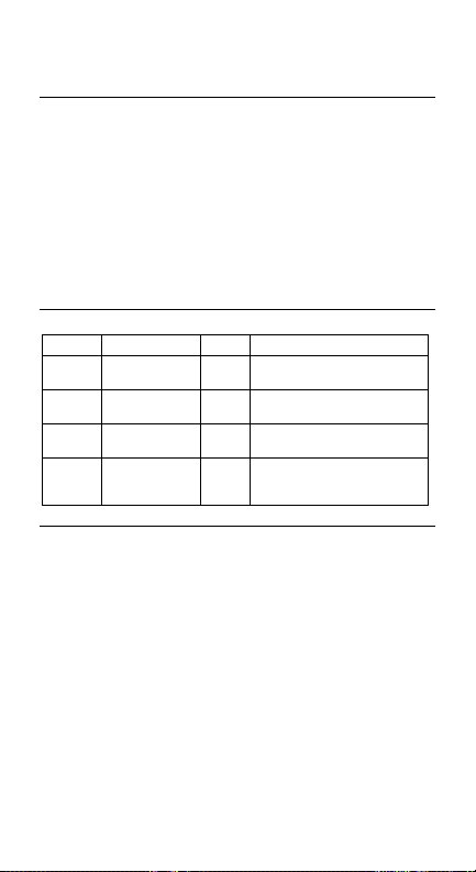
Instrument Familiarization (Fig. 1)
1. Transformer Jaws: Designed to pick up the AC current flowing through
the conductor.
2. Jaw Opening Lever: Press lever to open transformer jaws. When
pressure on lever is released, the jaws will close again.
3. Selector Switch: Turns instrument on and off and selects the
measuring function.
4. AC/DC selector switch (AC40B): With the selector switch set to voltage
measurement, this button selects between AC and DC voltage.
5. Data Hold Switch: Holds reading for all functions and ranges. Press
again to release HOLD before taking a new measurement.
6. Digital Display: 3-3/4 digit LCD (max reading 3999) with decimal point,
low battery N, Auto-range, Data Hold l, and unit indicators, plus,
for the AC meter: ACB, DCF, Polarity ) and continuity R.
7. Input Terminals (AC meters): Connect the black test lead to the “COM”
input and red lead to the “+” input when measuring voltage, resistance
and continuity (AC40B).
2
Page 5

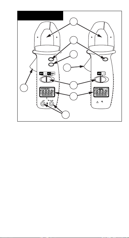
AC Current Measurement (Fig. 2)
1. Set the slide switch to ACB position.
2. Open spring-loaded clamp by pressing lever on left side of meter.
3. Position clamp around wire or conductor and release clamp lever.
Make sure that the conductor is centered in the clamp and that the
clamp is entirely closed. The clamp must be positioned around only
one conductor. If it is placed around two or more current carrying
conductors, the reading is FALSE.
4. Read the measured value on the display. If the measured value
exceeds the highest range for a period of time, overheating may occur.
Interrupt measurement.
Do not measure current on high-voltage conductors
(>600 V) in order to avoid risk of discharge and/or
incorrect reading.
AC & DC Voltage Measurement (AC40B) (Fig. 3)
1. Connect the black test lead to the COM input and the red test lead to
the “+” input.
2. Set the selector switch to V C position.
3. Press the AC DC button to select AC or DC voltage (B or F is
displayed).
4. Connect probe tips to circuit, in parallel to the load.
5. Read the measured value on the display.
Resistance & Continuity Measurement (AC40B) (Fig. 4)
1. Remove any voltage from resistance to be measured and discharge all
capacitors.
2. Connect the black test lead to the COM input and the red test lead to
the “+” input.
3. Set the selector switch to Ω R position.
4. Connect the probe tips across the circuit or resistance.
5. Read the measured value on the display.
The instrument emits a continuous tone and the R symbol is displayed
when the measured resistance is < 40 Ω.
Display Hold
Press the HOLD button to keep the measured value on the display for later
viewing. Press HOLD again to release the “Display Hold” function before
taking a new measurement. Display Hold can be applied to all measuring
functions.
Note
Specifications
General Specifications
Display: (AC40B & AD40B) 3-3/4 digit LCD (max. reading 3999).
Polarity Indication: Automatic, negative indicated, positive implied
Overrange Indication : “OL” indicated.
Measuring Principle: Dual slope integration.
Range Selection: Automatic.
Low Battery Indication: N when battery voltage falls below operating
voltage.
3
Page 6

Auto Power Off (APO): Approx. 30 minutes after no function change.
Environmental Conditions
This instrument is designed for indoor use.
Altitude: < 2000 m
Operating Temperature: 0 °C to +40 °C, <80 % R.H., non-condensing.
Storage Temperature: -10 °C to +60 °C, <70 % R.H., non-condensing,
batteries removed.
Power Supply: Two 1.5 V AAA batteries (UM-2).
Battery Life: Alkaline 300 hours, approx.
Maximum Jaw Opening: 25.4 mm.
Dimensions/Weight, AD40B (WxHxD): 64x190x36mm/250g (incl. battery).
Dimensions/Weight, AC40B (WxHxD): 64x190x36mm/280g (incl. battery).
Accessories: Manual, carrying case, test leads (AC40B).
Replacement Parts: Test lead set - TL245
Safety: meets EN 61010-1:2001 Cat III - 600V Pollution Degree: Level II,
EN 61010-2-032
EMC: meets EN61326-1.
Agency Approvals: P
This product complies with requirements of the following European
Community Directives: 89/336/EEC (Electromagnetic Compatibility)
and 73/23/EEC (Low Voltage) as amended by 93/68/EEC (CE Marking).
However, electrical noise or intense electromagnetic fields in the
vicinity of the equipment may disturb the measurement circuit.
Measuring instruments will also respond to unwanted signals that may
be present within the measurement circuit. Users should exercise care
and take appropriate precautions to avoid misleading results when
making measurements in the presence of electronic interference.
Electrical Specifications
Accuracy is ±(%reading + nbr digits) at 23 °C ±5 °C, <80 % R.H.
DC Voltage (AC40B)
Range Accuracy Resolution
400 V ±(1.2 %rdg +5 dgt) 0.1 V
600 V ±(1.2 %rdg +5 dgt) 1 V
Input Impedance: 1 MΩ
Overload Protection: 600 V rms
AC Voltage (AC40B)
Range Accuracy (40-450 Hz) Resolution
400 V ±(1.5 %rdg +10 dgt) 0.1 V
600 V ±(1.5 %rdg +10 dgt) 1 V
Input Impedance: 1 MΩ
Measuring method: Dual slope integration. Average Sensing, rms
indication. Overload Protection: 600 V rms
AC Current (AC40B/AD40B)
Range Accuracy (50/400 Hz) Resolution
40 A ±(2.0 %rdg +10 dgt) 0.01 A
400 A ±(2.0 %rdg +10 dgt) 0.1 A
Overload Protection: 660 A Accuracies are specified for conductor
centered in the jaw. If the conductor is not centered, an additional error
of max 1.5 % can result.
4
Page 7

Measuring method: Dual slope integration. Average Sensing, rms
indication.
Resistance (AC40B)
Range Accuracy Resolution
400 Ω ±(1.0 %rdg + 5 dgt) 0.1 Ω
Max open circuit voltage, AC40B: -1.2 V nominal
Overload Protection, AC40B: 600 Vrms
Audible Continuity (AC40B)
Like resistance measurement. Continuous tone and R display at R ≤40 Ω
for AC40B
Max open circuit voltage: -1.2 V
Overload Protection: 600 Vrms
Data Hold: Hold display reading for all functions and ranges. Always
remember to release Data Hold when taking a new measurement.
Troubleshooting & Maintenance
In case of malfunction during the operation of the meter, the following
steps should be performed in order to isolate the cause of the problem:
1. Check the batteries.
2. Review the operating instructions for possible mistakes in operating
procedure.
3. Check clamp against a known current source.
4. Check test leads for continuity (voltage and resistance).
Except for the replacement of the batteries, repair of the clamp should be
performed only by a Factory Authorized Service Center or by other
qualified instrument service personnel.
Front panel and case can be cleaned with a mild solution of detergent and
water. Apply sparingly with a soft cloth and let dry completely before
using. Do not use aromatic hydrocarbons or chlorinated solvents for
cleaning.
Battery Replacement
The meter is powered by two 1.5 V AAA batteries. Replace batteries as
soon as N symbol is displayed.
1. Turn meter off. Disconnect and remove the test leads.
2. Position the meter face down. Remove the two screws and lift off rear
case.
3. Replace the batteries.
4. Reassemble the case.
5
Page 8

Repair
All test tools returned for warranty or non-warranty repair or for calibration
should be accompanied by the following: your name, company’s name,
address, telephone number, and proof of purchase. Additionally, please
include a brief description of the problem or the service requested and
include the test leads with the meter. Non-warranty repair or replacement
charges should be remitted in the form of a check, a money order, credit
card with expiration date, or a purchase order made payable to Amprobe
Test Tools.
In-Warranty Repairs and Replacement – All Countries
Please read the warranty statement and check your battery before
requesting repair. During the warranty period any defective test tool can be
returned to your Amprobe® Test Tools distributor for an exchange for the
same or like product. Please check the “Where to Buy” section on
www.amprobe.com for a list of distributors near you. Additionally, in the
United States and Canada In-Warranty repair and replacement units can
also be sent to a Amprobe® Test Tools Service Center (see below for
address).
Non-Warranty Repairs and Replacement – US and Canada
Non-warranty repairs in the United States and Canada should be sent to a
Amprobe® Test Tools Service Center. Call Amprobe® Test Tools or inquire
at your point of purchase for current repair and replacement rates.
In USA In Canada
Amprobe® Test Tools Amprobe® Test Tools
Everett, WA 98203 Mississauga, ON L4Z 1X9
Tel: 888-993-5853 Tel: 905-890-7600
Fax: 425-446-6390 Fax: 905-890-6866
Non-Warranty Repairs and Replacement – Europe
European non-warranty units can be replaced by your Amprobe® Test
Tools distributor for a nominal charge. Please check the “Where to Buy”
section on www.amprobe.com for a list of distributors near you.
European Correspondence Address*
Amprobe® Test Tools Europe
P.O. Box 1186
5602 BD Eindhoven
The Netherlands
*(Correspondence only – no repair or replacement available from this
address. European customers please contact your distributor).
®
6
Page 9
Clamp Meter
1
1
CAT III
600V
HOLD
AC
DC
A
2
CAT III
5
4
600V
HOLD
A
AC40B
2
100 20 4030
CAT 600V
400A
MAX
600V
COM
MAX
3
6
AD40B
100 20 4030
CAT 600V
MAX400A
7
7
Page 10
2
Current
CAT III
AC40B
COM
HOLD
A
CAT 600V
400A
600V
AC
DC
MAX
600V
MAX
3
AC40B
COM
HOLD
A
CAT 600V
400A
600V
600V
AC
DC
3
2
4
5
MAX
MAX
1
CAT III
8
Page 11

4
CAT III
600V
1
HOLD
AC
DC
A
3
4
AC40B
COM
CAT 600V
400A
600V
MAX
MAX
5
2
5
AAA
AAA
9
Page 12

10
Page 13

AD40B, AC40B
Mini Clamp Meters
Users Manual
• Bedienungshandbuch
• Manual de uso
• Mode d’emploi
German
Deutsch
Page 14

Beschränkte Gewährleistung und
Haftungsbeschränkung
Es wird gewährleistet, dass dieses Amprobe
für die Dauer von einem Jahr ab dem Kaufdatum frei
-Produkt
von Material- und Fertigungsdefekten ist. Diese
Gewährleistung erstreckt sich nicht auf Sicherungen,
Einwegbatterien oder Schäden durch Unfälle,
Nachlässigkeit, Missbrauch, Änderungen oder
abnormale Betriebsbedingungen bzw. unsachgemäße
Handhabung. Die Verkaufsstellen sind nicht dazu
berechtigt, diese Gewährleistung im Namen von
Amprobe
Gewährleistungsperiode Serviceleistungen zu
zu erweitern. Um während der
beanspruchen, das Produkt mit Kaufnachweis an ein
autorisiertes Amprobe
an einen Amprobe
Einzelheiten siehe Abschnitt „Reparatur“ oben. DIESE
Test Tools Service-Center oder
-Fachhändler/-Distributor einsenden.
GEWÄHRLEISTUNG STELLT DEN EINZIGEN UND
ALLEINIGEN RECHTSANSPRUCH AUF
SCHADENERSATZ DAR. ALLE ANDEREN
GEWÄHRLEISTUNGEN - VERTRAGLICH GEREGELTE
ODER GESETZLICHE VORGESCHRIEBENE EINSCHLIESSLICH DER GESETZLICHEN
GEWÄHRLEISTUNG DER MARKTFÄHIGKEIT UND DER
EIGNUNG FÜR EINEN BESTIMMTEN ZWECK, WERDEN
ABGELEHNT DER HERSTELLER ÜBERNIMMT KEINE
HAFTUNG FÜR SPEZIELLE, INDIREKTE, NEBEN- ODER
FOLGESCHÄDEN ODER VERLUSTE, DIE AUF
BELIEBIGER URSACHE ODER RECHTSTHEORIE
BERUHEN. Weil einige Staaten oder Länder den
Ausschluss oder die Einschränkung einer implizierten
Gewährleistung sowie von Begleit- oder Folgeschäden
nicht zulassen, ist diese Gewährleistungsbeschränkung
möglicherweise für Sie nicht gültig.
Page 15

Mini Clamp Meters
Inhalt
Symbole.................................................................................................... 1
Warnungen und Vorsichtsmaßnahmen..................................................... 1
Einleitung.................................................................................................. 2
Vorstellung des Gerätes (Fig. 1)................................................................ 2
Wechselstrommessung (Fig. 2) ................................................................2
Gleich- und Wechselspannungsmessung (AC40B) (Fig. 3)....................... 3
Widerstands- und Durchgangsmessung (AC40B) (Fig. 4) ........................ 3
Anzeigesperre ........................................................................................... 3
Spezifikationen.......................................................................................... 3
Fehlersuche und Wartung ......................................................................... 5
Reparatur.................................................................................................. 6
Hinweis: Abbildungen befinden sich am Ende des englischen Abschnitts.
Symbole
Batterie
Β
Schutzisoliert
T
Gleichstrom
F
Wechselstrom
B
Übereinstimmung mit
EU-Richtlinien
P
Warnungen und Vorsichtsmaßnahmen
• Dieses Gerät ist EN61010-1:2001 und EN61010-2-32 zertifiziert für
Installationsklasse III. Anwendung ist empfohlen auf lokaler
Verteilerebene, mit Elektrogeräten, tragbaren Geräten, usw, wo nur
kleinere Überspannungsspitzen auftreten können, jedoch nicht für
Starkstromnetze und Hochspannungsanlagen
• Dieses Gerät darf nicht mit nichtisolierten Leitern bei Spannungen
höher als 600 V AC/DC verwendet werden
• Seien Sie äußerst vorsichtig wenn Sie an nicht-isolierten Leitern
und Stromschienen messen
• Überschreiten Sie nie die kontinuierlichen Überlastgrenzen der
verschiedenen Meßfunktionen (siehe Spezifikationen) oder andere
Grenzen welche auf dem Gerät markiert sind
• Vorsicht beim Messen von Spannungen >60 V DC oder 30 V AC//
Strömen >10 mA // Netzstrom/-spannung bei induktiever Last oder
bei Gewittern // beim Messen an Bildröhrgeräten (hohe
Spannungsspitzen)
Im Handbuch nachlesen.
W
Gefährliche Spannung
X
Erde, Masse
J
Akustischer Alarm
R
Anwendung in der
,
Umgebung von
gefährlichen
stromführenden Leitern
zulässig.
1
Page 16

• Keine Strommessung vornehmen mit eingesteckten Meßkabeln
• Unsersuchen Sie Gerät, Meßkabel, Verbinder, usw. vor jeder
Messung. Beschädigte Teile nicht verwenden
• Keine Strommessung vornehmen mit eingesteckten Meßkabeln
• Unsersuchen Sie Gerät, Meßkabel, Verbinder, usw. vor jeder
Messung. Beschädigte Teile nicht verwenden
• Meßspitzen und Stromkreis während der Messung nicht berühren.
Sich selbst isolieren
• Das Messgerät darf nur wie in diesem Handbuch beschrieben
eingesetzt werden, da die Sicherheitsschaltkreise des Messgeräts
ansonsten u.U. keinen Schutz bieten
• Bei Arbeiten im Bereich von unisolierten Leitern extreme Vorsicht
walten lassen. Berührung mit dem Leiter kann Stromschlag
verursachen
• Der Wulst oben am Zangenkörper dient dazu, die Hände und Finger
von gefährlichen stromführenden Leitern fernzuhalten
Einleitung
Der AD40B ist ein mittelwertmessender und Effektivwert (Sinuswelle)
anzeigender AC Stromzangen-Multimeter. Der AC40B ist ein
mittelwertmessender und Effektivwert (Sinuswelle) anzeigender AC
Stromzangen-Multimeter, der auch AC und DC Spannung, Widerstand und
Durchgang mißt.
Auspacken
Die Verpackung sollte enthalten: eine digitale Meßzange, eine Tragetasche,
zwei 1.5 V AAA (UM-2) Knopfzellen (im Gerät) und diese Anleitung, plus,
für den AC40B , ein Paar Meßkabel (eins schwarz, eins rot). Sollte ein Teil
beschädigt sein oder fehlen, kehren Sie bitte für einen Umtausch zur
Verkaufsstelle zurück.
Vorstellung des Gerätes (Fig. 1)
1. Stromzange: Überträgt den Strom der durch den Leiter fließt.
2. Zangenhebel: Hebel drücken um Zange zu öffnen. Zange schließt beim
Loslassen des Hebels.
3. Funktionsschalter: Schaltet Gerät ein und aus und wählt die
Meßfunktion.
4. AC/DC Schalter (AC40B): Mit dem Funktionsschalter auf
Spannungsmessung, wählt dieser Schalter zwischen Gleich- und
Wechselspannung.
5. Data Hold Taste: Friert die Anzeige für alle Bereiche und Funktionen.
HOLD Taste immer lösen bevor Sie eine neue Messung vornehmen.
6. Digitale Anzeige: 3-3/4 Digit LCD (max Ablesung 3999) mit
Dezimalpunkt-, Entladene Batterie- N, Auto-Bereich, Data Hold-l ,
und Einheitsanzeigen, plus, für AC meter: ACB, DCF, Polarität- und
Durchgangs- R Anzeigen.
7. Eingänge (AC Meter): Das schwarze Meßkabel für Spannungs-,
Widerstandsund Durchgangsmessung immer mit COM Eingang und
rotes immer mit “+” Eingang verbinden (AC40B).
Wechselstrommessung (Fig. 2)
1. Wahlschalter auf ACB stellen.
2. Zange durch Drücken des Hebels öffnen.
2
Page 17

3. Zange um Stromkabel bringen und schließen (durch Loslassen des
Hebels). Stellen Sie sicher daß nur ein Kabel in der Zange ist und daß
die Zange gut geschlossen ist. Bei mehreren Kabeln in der Zange
währe die Messung falsch.
4. Lesen Sie den Meßwert auf der Anzeige. Wenn der Meßwert einige Zeit
den höchsten Bereich überschreitet, kann Überhitzung auftreten.
Messung unterbrechen.
Messen Sie keinen Strom an Hochspannungsleitungen
(>600 V) um elektrischen Schlag und/oder Meßfehler zu
vermeiden.
Anmerkung
Gleich- und Wechselspannungsmessung (AC40B)
(Fig. 3)
1. Schwarzes Meßkabel mit COM und rotes mit “+” Eingang verbinden.
2. Wahlschalter auf (insert Amps AC DC symbol) stellen.
3. (insert AC/DC key cap) Taste drücken um AC oder DC Spannung zu
wählen (B oder F wird angezeigt).
4. Meßspitzen mit Schaltkreis verbinden (parallel mit Spannungsquelle).
5. Meßwert ablesen.
Widerstands- und Durchgangsmessung (AC40B)
(Fig. 4)
1. Jede Spannung vom Meßkreis entfernen und Kondensatoren entladen.
2. Schwarzes Meßkabel mit COM und rotes mit “+” Eingang verbinden.
3. Wahlschalter auf Ω R stellen.
4. Meßspitzen mit Meßkreis verbinden.
5. Meßwert ablesen.
Akustisches Signal und R Anzeige wenn Widerstand < 40 Ω.
Anzeigesperre
Durch Drücken der HOLD Taste bleibt die Anzeige für späteres Ablesen
erhalten. HOLD vor einer neuen Messung erneut drücken um die Anzeige
frei zu geben. HOLDsteht für alle Meßfunktionen zur Verfügung.
Spezifikationen
Allgemeine Spezifikationen
Anzeige: (AC40B & AD40B) 3-3/4 stelliges LCD (max. Ablesung 3999).
Polaritätsanzeige: Automatisch, negativ angezeigt, positiv unterstellt
Überlastanzeige : “OL”.
Meßart: Doppelte Rampenintegration.
Bereichswahl: Automatisch.
Entladene Batterieanzeige: N wenn Batteriespannung unter
Betriebsspannung fällt.
Automatische Abschaltung (APO): nach ungefähr 30 Minuten Inaktivität.
Umgebungsbedingungen
Dieses Gerät ist für Binnenbetrieb bestimmt.
Höhenlage: < 2000 m.
Betriebstemperatur: 0 °C bis +40 °C, <80 % R.F., nicht kondensierend.
3
Page 18

Lagertemperatur: -10 °C bis +60 °C, <70 % R.F., nicht kondensierend,
Batterien entfernt.
Stromversorgung: zwei 1.5 V AAA Knopfzellen (UM-2).
Batterielebensdauer: Alkali 200 Stunden, approx.
Max. Zangenöffnung: 25.4 mm.
Abmess./Gewicht, AD Meter (LxHxB): 64x190x36mm/250g (mit Batterien).
Abmess./Gewicht, AC Meter (LxHxB): 64x190x36mm/280g (mit Batterien).
Zubehör: Batterien, Anleitung, Tragetasche, Meßkabel (für AC Meter)
Ersatzzubehör: Ein Meßkabelsatz - TL245
Sicherheit: EN 61010-1:2001 Cat III – 600 V Pollutionsgrad: Niveau II, EN
61010-2-032.
EMC: gemäß EN61326-1.
Xulsddungrn: P
Dieses Produkt beantwortet an die Bestimmungen der folgenden EWG
Richtlinien: 89/336/EEC (Elektromagnetische Kompatibilität) und
73/23/EEC (Niedrige Spannung) geändert durch 93/68/EEC (CE
Marking). Elektrisches Rauschen und starke magnetische Felder in der
direkten Umgebung des Meßgerätes können jedoch den Meßkreis
beeinflussen. Das Gerät kann auch durch Störsignale im gemessenen
Schaltkreis beeinflußt werden. Der Anwender muß
Vorsichtsmaßnahmen treffen um irreführende Meßergebnisse bei
Messungen in der Umgebung von starken elektromagnetischen
Feldern zu vermeiden.
Elektrische Spezifikationen
Genauigkeit ist ±(%Ablesung + Anz. Digits) bei 23 °C ±5 °C, <80 % R.F.
Gleichspannung (AC40B)
Bereich Genauigkeit Auflösung
400 V ±(1.2 %vMW +5 Dgt) 0.1 V
600 V ±(1.2 %vMW + 5 Dgt) 1 V
Eingangsimpedanz: 1 MΩ
Überlastschutz: 600 V rms
Wechselspannung (AC40B)
Bereich Genauigk.(40-450 Hz) Auflösung
400 V ±(1.5 %vMW + 10 Dgt) 0.1 V
600 V ±(1.5 %vMW + 10 Dgt) 1 V
Eingangsimpedanz: 1 MΩ
Meßart: Doppelte Rampenintegration – Mittelwertmessung mit
Effektivwertanzeige (Sinuswelle). - Überlastschutz: 600 V eff
Wechselstrom (AC40B/AD40B)
Bereich Genauigk. (50/400 Hz) Auflösung.
40 A ±(2.0 %vMW +10 Dgt) 0.01 A
400 A ±(2.0 %vMW +10 Dgt) 0.1 A
Überlastschutz: 660 A
Die angegebenen Genauigkeiten sind gültig wenn der Stromleiter in der
Zange zentriert ist. Bei nicht-zentriertem Leiter kann eine zusätzliche
Ungenauigkeit von 1.5 % auftreten.
Meßart: Doppelte Rampenintegration – Mittelwertmessung mit
Effektivwertanzeige (Sinuswelle).
4
Page 19

Widerstand (Automatische Bereichswahl) (AC40B)
Bereich Genauigkeit Auflösung
400 Ω ±(1.0 %vMW + 5 Dgt) 0.1 Ω
Max Leerlaufspannung:AC40B: -1.2 V nominal Überlastschutz:AC40B:
600 V rms
Durchgangstest (AC40B)
Wie Durchgangsmessung. Akustisches Signal und Anzeige bei ≤40 Ω
(AC40B).
Max Leerlaufspannung: -1.2 V nominal; Überlastschutz: 600 Vrms.
Anzeigesperre (HOLD): Friert die Anzeige für alle Funktionen und
Bereiche. Hold desaktivieren um eine neue Messung vorzunehmen.
Fehlersuche und Wartung
Bei Problemen bitte folgendes prüfen:
1. Batterie Ladung,
2. Meßprozedur
3. Einen bekannten Stromwert mit der Zange prüfen.
4. Meßkabel prüfen (Spannungs-und Widerstandsmessung).
Mit Ausnahme des Batteriewechsels sollte jede Reparatur der Stromzange
nur durch eine Wavetek-anerkannte Servicestelle vorgenommen werden.
Das Gehäuse kann mit einer milden Seifenlösung gereinigt werden. Vor
Gebrauch gut trocknen lassen.
Batteriewechsel
1. Das Gerät wird durch zwei 1.5 V AAA Knopfzellen betrieben. Batterien
wechseln, sobald N angezeigt wird.
2. Gerät abschalten und Meßkabel entfernen.
3. Zwei Schrauben von Rückseite entfernen und Geräterückseite abheben.
n Batterien ersetzen und Gerät wieder zusammensetzen.
5
Page 20

Reparatur
Zu allen Geräten, die zur Reparatur oder Kalibrierung im Rahmen der
Garantie oder außerhalb der Garantie eingesendet werden, muss folgendes
beigelegt werden: Name des Kunden, Firmenname, Adresse,
Telefonnummer und Kaufbeleg. Zusätzlich bitte eine kurze Beschreibung
des Problems oder der gewünschten Wartung sowie die Messleitungen
dem Messgerät beilegen. Die Gebühren für Reparaturen außerhalb der
Garantie oder für den Ersatz von Instrumenten müssen als Scheck,
Geldanweisung, Kreditkarte (Kreditkartennummer mit Ablaufdatum)
beglichen werden oder es muss ein Auftrag an Amprobe® Test Tools
formuliert werden.
Garantiereparaturen oder -austausch - alle Länder
Bitte die Garantieerklärung lesen und die Batterie prüfen, bevor
Reparaturen angefordert werden. Während der Garantieperiode können
alle defekten Geräte zum Umtausch gegen dasselbe oder ein ähnliches
Produkt an den Amprobe® Test Tools-Distributor gesendet werden. Ein
Verzeichnis der zuständigen Distributoren ist im Abschnitt “Where to Buy”
(Verkaufsstellen) auf der Website www.amprobe.com zu finden. Darüber
hinaus können in den USA und in Kanada Geräte an ein Amprobe® Test
Tools Service-Center (Adresse siehe weiter unten) zur Reparatur oder zum
Umtausch eingesendet werden.
Reparaturen und Austausch außerhalb der Garantie - USA und Kanada
Für Reparaturen außerhalb der Garantie in den Vereinigten Staaten und in
Kanada werden die Geräte an ein Amprobe® Test Tools Service-Center
gesendet. Auskunft über die derzeit geltenden Reparatur- und
Austauschgebühren erhalten Sie von Amprobe® Test Tools oder der
Verkaufsstelle.
In den USA: In Kanada:
Amprobe® Test Tools Amprobe® Test Tools
Everett, WA 98203 Mississauga, ON L4Z 1X9
Tel.: 888-993-5853 Tel.: 905-890-7600
Fax: 425-446-6390 Fax: 905-890-6866
Reparaturen und Austausch außerhalb der Garantie - Europa
Geräte außerhalb der Garantie können durch den zuständigen Amprobe®
Test Tools-Distributor gegen eine Gebühr ersetzt werden. Ein Verzeichnis
der zuständigen Distributoren ist im Abschnitt “Where to Buy”
(Verkaufsstellen) auf der Website www.amprobe.com zu finden.
Korrespondenzanschrift für Europa*
Amprobe® Test Tools Europe
P. O. Box 1186
5602 BD Eindhoven
Niederlande
*(Nur Korrespondenz – keine Reparaturen, kein Umtausch unter dieser
Anschrift. Kunden in Europa wenden sich an den zuständigen Distributor).
6
Page 21

AD40B, AC40B
Mini Clamp Meters
Users Manual
• Bedienunghandbuch
• Manual de uso
• Mode d’emploi
Spanish
Español
Page 22

Garantía limitada y Limitación de responsabilidad
Su producto Amprobe
material y mano de obra durante 1 año a partir de la
estará libre de defectos de
fecha de adquisición. Esta garantía no cubre fusibles,
baterías descartables o daños que sean consecuencia
de accidentes, negligencia, uso indebido, alteración,
contaminación o condiciones anormales de operación o
manipulación. Los revendedores no están autorizados a
extender ninguna otra garantía en nombre de
Amprobe
garantía, regrese el producto con una prueba de compra
a un centro de servicio autorizado por Amprobe
equipos de comprobación o a un concesionario o
distribuidor de Amprobe
Reparación que aparece más arriba para obtener
. Para obtener servicio durante el período de
de
. Consulte la sección
detalles. ESTA GARANTÍA CONSTITUYE SU ÚNICO
RESARCIMIENTO. TODAS LAS DEMÁS GARANTÍAS,
TANTO EXPRESAS, IMPLÍCITAS O ESTATUTARIAS,
INCLUYENDO LAS GARANTÍAS IMPLÍCITAS DE
ADECUACIÓN PARA UN PROPÓSITO DETERMINADO O
COMERCIABILIDAD, QUEDAN POR LA PRESENTE
DESCONOCIDAS. El fabricante no deberá ser
considerado responsable de ningún daño o pérdida
tanto especiales, indirectos, contingentes o resultantes
que surjan de cualquier causa o teoría. Debido a que
ciertos estados o países no permiten la exclusión o
limitación de una garantía implícita o de los daños
contingentes o resultantes, esta limitación de
responsabilidad puede no regir para usted.
Page 23

Mini Clamp Meter
Contenidos
Símbolos................................................................................................... 1
Advertencias y Precauciones .................................................................... 1
Introducción.............................................................................................. 2
Familiarización con el instrumento (vea fig. 1).......................................... 2
Medida de Corriente CA (vea fig. 2) .......................................................... 3
Medida de Tensión CC y CA (AC40B) (fig. 3) ............................................ 3
Medida de Resistencia y de Continuidad (AC40B) (fig. 4)........................ 3
Lectura congelada en pantalla................................................................... 3
Especificaciones........................................................................................ 3
Reparación y Mantenimiento .................................................................... 5
Reparación................................................................................................ 6
Nota: Las figuras se muestran al final de la sección en inglés.
Símbolos
Batería
Β
Aislamiento
T
doble
Corriente
F
continua
Corriente alterna
B
Cumple con las
directivas de la
P
Unión Europea.
Advertencias y Precauciones
• Este instrumento está homologado según EN61010-1:2001 y
EN61010-2-32 para la Categoría de Instalación III. Su uso está
recomendado en el nivel local de distribución de energía,
electrodomésticos, equipos portátiles, etc, donde se producen
niveles transitorios de sobretensión reducidos, pero no en líneas
pricipales de suministro, líneas aéreas o sistemas de cable.
• No debe utilizarse este instrumento sobre hilos sin aislar a
tensiones superiores a 600 V CA/CC
• Extreme las precauciones cuando trabaje con cables desnudos y
conexiones principales
• No supere nunca los límites de entrada para las diferentes
funciones (vea Especificaciones), ni los límites marcados en el
instrumento.
Consulte el manual
W
Tensión peligrosa
X
Conexión a tierra
J
Señal acústica
R
Se permite la aplicación en
,
conductores vivos
peligrosos, así como su
desconexión de ellos.
1
Page 24

• Tenga especial cuidado: al medir tensión >60 V CC o 30 V CA //
corriente >10 mA // tensión de red de CA con cargas inductivas //
tensión de red de CA durante tormentas eléctricas // mientras
trabaja con pantallas TRC.
• Nunca mida corriente mientras las puntas de prueba se encuentren
conectadas.
• Inspeccione siempre el multímetro, las puntas de prueba y los
accesorios antes de cada uso. No utilice ningún componente
dañado.
• Nunca se ponga Ud. a tierra cuando esté tomando medidas. No
toque nunca circuitos expuestos ni partes metálicas. Mantenga su
cuerpo aislado de tierra.
• No utilice el instrumento en ambientes potencialmente explosivos.
• No use ningún tipo de equipo sin conocerlo previamente. Lea y siga
las instrucciones antes de usarlo.
• Utilice el multímetro sólo como se especifica en este manual; de lo
contrario, es posible que los circuitos de seguridad del medidor no
lo protejan.
• Tenga extrema precaución al trabajar con conductores desnudos. El
contacto con ellos puede producir descargas eléctricas.
• La saliente en la parte superior del cuerpo de la pinza está diseñada
para mantener manos y dedos alejados de los conductores vivos
peligrosos.
Introducción
El AD40B es una sonda de medición de corriente en alterna, midiendo el
valor medio de la onda senoidal. El AC40B es una sonda de medición de
corriente en alterna, midiendo el valor medio de la onda senoidal,
pudiendo medir también voltajes en contínua y alterna, resistencia y
continuidad.
Desembalaje e inspección
El embalaje debe contener el multímetro de pinza, un estuche de
transporte, dos pilas de 1.5 V AAA (UM-2) (instaladas), y este manual –
más para el medidor AC40B, un juego de puntas (una negra y otra roja). Si
falta algún componente u observa daños, devuelva el conjunto al lugar
donde lo adquirió para que se lo cambien.
Familiarización con el instrumento (vea fig. 1)
1. Pinza del transformador: Diseñada para captar la corriente alterna que
fluye por el hilo.
2. Palanca de apertura de la pinza: Presione sobre esta palanca para abrir
la pinza del transformador. La pinza se cierra de nuevo al liberar la
presión.
3. Selector de función: Selecciona el interruptor de encendido y apagado
y las funciones de medición.
4. Selector de alterna/contínua: Con el selector en posición de medir
voltaje, elija entre contínua o alterna.
5. Tecla de retención de datos: (HOLD) Congela la lectura en todas las
funciones.
6. Pantalla digital: visualizador LCD de 3-3/4 dígitos (lectura máxima
3999) con punto decimal, indicadores de batería baja N, auto rango,
Data Hold l, y unidades, más para los medidores del tipo AC: ACB,
DCF, polaridad − y continuidad R.
2
Page 25

7. Terminales de entrada: La punta de prueba negra se conecta siempre a
la entrada “COM”, y la roja a la entrada “+“, para medir tensión,
resistencia y continuidad (AC40B).
Medida de Corriente CA (vea fig. 2)
1. Ponga el conmutador deslizante en la posición ACB
2. Abra la pinza de resorte, presionando sobre la palanca situada en el
lado izquierdo del medidor.
3. Rodee el hilo o el conductor con la pinza y suelte la palanca para
cerrarla. Asegúrese de que la pinza queda completamente cerrada. La
pinza debe rodear un solo conductor. Si se coloca rodeando dos o más
conductores con corriente, la medida será FALSA.
4. Lea el valor medido en pantalla. Si dicho valor, excede el máximo en el
tiempo establecido, podría ocasionar sobrecalentamientos. Interrumpa
la medición.
Ne mesurez pas des courants sur des lignes de haute
tension (>600 V) afin d’éviter des chocs électriques et/ou
des mesures erronnées.
Medida de Tensión CC y CA (AC40B) (fig. 3)
1. Conecte la punta de prueba negra al terminal “COM” y la roja al
terminal “+“.
2. Ponga el conmutador deslizante en la posición.
3. Pulse el botón para seleccionar mediciones en alterna o contínua (se
mostrará B ó F en pantalla).
4. Toque los puntos del circuito con las puntas metálicas.
5. Lea el valor de la medida.
Note
Medida de Resistencia y de Continuidad (AC40B)
(fig. 4)
1. Asegúrese de que el circuito sometido a prueba no tiene alimentación.
Descargue todos los condensadores.
2. Conecte la punta de prueba negra al terminal “COM”, y la roja al
terminal “+“.
3. Ponga el conmutador deslizante en la posición Ω R.
4. Conecte las puntas de prueba al circuito.
5. Lea el valor de la medida.
El zumbador suena (y se mostrará R en pantalla)si la resistencia es menor
de 40 Ω.
Lectura congelada en pantalla
Pulse la tecla “HOLD”, lo cual retendra la lectura en pantalla del valor
medido. Vuelva a pulsar “HOLD” para desconectar esta función antes de
tomar una nueva medida. Esta función se puede usar para cualquier tipo
de medición.
Especificaciones
Especificaciones Generales
Visualizador: (AC40B & AD40B) LCD de 3-3/4 digitos (lectura máxima
3999).
3
Page 26

Indicador de polaridad: Automático, indicación negativa, implicación
positiva.
Indicación de sobrecarga: Anunciador “OL”.
Principio de medición: Doble integración.
Rango seleccionado: Automático.
Indicación de “pila baja”: N. No se garantiza la precisión.
Apagado automático (APO): después de unos 30 minutos sin cambiar de
función.
Condiciones Ambientales
Este instrumento está diseñado para ser usado en interiores.
Altitud: < 2000 m.
Temperatura de funcionamiento: 0 a 40 ºC, H.R. <80 %, sin condensación.
Temp. de almacenamiento: -10 a 60 ºC, H.R. <70 %, sin condensación, sin
pila.
Alimentación: 2 pilas de 1.5 V AAA (UM-2).
Duración de la pila (típica): 300 horas (alcalina).
Máxima apertura de la pinza: 25.4 mm.
Dimensiones, AD40B (An x Al x Pr): 64x190x36 mm; Peso: 250 g.
Dimensiones, AC40B (An x Al x Pr): 65x190x36 mm; Peso: 280 g.
Accesorios: manual de instrucciones, estuche de transporte, puntas de
prueba (AC40B).
Repuestos: Juego de Sondas TL245.
Seguridad: según normas EN 61010-1:2001 Cat III - 600V Grado de
contaminación: Nivel II, EN 61010-2-032.
EMC: según EN61326-1.
Aprobaciones de agencias: P
Este producto cumple los requisitos de las siguientes Directivas de la
Comunidad Europea: 86/336/ EEC (Compatibilidad Electromagnética) y
73/23/EEC (Baja Tensión), con enmiendas según 93/68/EEC (Marcado
CE). No obstante, la presencia de ruido eléctrico o campos
electromagnéticos intensos en las proximidades del equipo pueden
introducir perturbaciones en los circuitos de medida. Los
instrumentos de medida también responden a las señales no deseadas
que puedan estar presentes en los circuitos de medida. El usuario
deberá tomar las precauciones necesarias para evitar obtener
resultados incorrectos cuando realiza medidas en presencia de
interferencias electromagnéticas.
Especificaciones Eléctricas
Precisión: ±(% de lectura + no de dígitos), a 23 ±5 ºC, H.R. <80 %.
Tensión CC (AC40B)
Escala Precisión Resolución
400 V ±(1.2 %lect +5 dgt) 0.1 V
600 V ±(1.2 %lect +5 dgt) 1 V
Impedancia de entrada: 1 MΩ.
Protección sobrecarga: 600 V rms
Tensión CA (AC40B)
4
Page 27

Escala Precisión (40-450 Hz) Resolución
400 V ±(1.5 %lect +10 dgt) 0.1 V
600 V ±(1.5 %lect + 10 dgt) 1 V
Impedancia de entrada: 1 MΩ
Tipo de medida: promediado, indicación de valor eficaz (onda sinusoidal).
Protección sobrecarga: 600 V rms.
Corriente CA (AC40B/AD40B)
Escala Precisión (50/400 Hz) Resolución
40 A ±(2.0 %lect +10 dgt) 0.01 A
400 A ±(2.0 %lect + 10 dgt) 0.1 A
Protección sobrecarga: 600 A
La precisión de medida está diseñada para cuando el conductor se
encuentra en el centro de la mordaza de medición, en caso de no
estarlo, se podría tener un error adicional del 1.5 % máximo.
Tipo de medida: promediado, indicación de valor eficaz (onda sinusoidal).
Resistencia (Escala automática) (AC40B)
Escala Precisión Resolución
400 Ω ±(1.0 % lect + 5 dgt) 0.1 Ω
Máxima tensión de circuito abierto, AC40B: -1.2 V nominal.
Protección sobrecarga, AC40B: 600 Vrms.
Indicación de continuidad (AC40B)
Un zumbador interno suena cuando la resistencia es menor de 40 Ω
(AC40B). Indicación de R.
Máxima tensión de circuito abierto, AC40B: -1.2 V nominal.
Protección sobrecarga, AC40B: 600 Vrms.
Retención de datos: N HOLD congela la lectura en el visualizador, en
todas las funciones y escalas. Libere siempre HOLD antes de tomar
una nueva medida.
Reparación y Mantenimiento
Si observa alguna anomalía en el medidor, haga lo siguiente para
identificar la causa del problema:
1. Compruebe la pila.
2. Repase las instrucciones de manejo por si hubiera cometido algún
error.
3. Aplique la pinza a una corriente de valor conocido.
4. Excepto la sustitución de la pila, cualquier otro trabajo de reparación
debe realizarse en un Centro de Servicio autorizado o por personas
cualificadas para la reparación de este tipo de instrumentos.
Para limpiar el panel frontal y la carcasa puede utilizar una solución suave
de detergente y agua. Aplíquela en poca cantidad con un paño suave y deje
que se seque bien antes de utilizar el medidor.
Sustitución de las Pilas
El medidor está alimentado por dos baterías del tipo botón de 1.5 voltios
AAA unitarios. Cambie las baterías, tan pronto como aparezca el símbolo
N en pantalla.
1. Apague el medidor. Desconecte y retire las puntas de prueba.
2. Ponga el medidor mirando hacia abajo. Extraiga los dos tornillos y
levante la tapa posterior.
3. Cambie las pilas.
4. Vuelva a cerrar la tapa.
5
Page 28

Reparación
Todas las herramientas de comprobación devueltas para su calibración o
reparación, cubiertas o no por la garantía, deberán estar acompañadas por
lo siguiente: su nombre, el nombre de la empresa, la dirección, el número
de teléfono y una prueba de compra. Además, incluya una breve
descripción del problema o del servicio solicitado y las puntas de prueba
del medidor. Los pagos correspondientes a reparaciones o reemplazos no
cubiertos por la garantía se deben remitir a la orden de Amprobe® Test
Tools en forma de cheque, giro postal, pago mediante tarjeta de crédito
(incluir el número y la fecha de vencimiento) u orden de compra.
Reparaciones y reemplazos cubiertos por la garantía – Todos los países
Antes de solicitar una reparación sirvase leer la declaración de garantía y
compruebe el estado de la pila. Durante el periodo de garantía, toda
herramienta de comprobación en mal estado de funcionamiento puede ser
devuelta al distribuidor de Amprobe® Test Tools para cambiarla por otra
igual o un producto semejante. Consulte la sección “Dónde comprar” del
sitio www.amprobe.com en Internet para obtener una lista de los
distribuidores de su zona. Además, en los Estados Unidos y Canadá las
unidades para reparación y reemplazo cubiertas por la garantía también se
pueden enviar a un Centro de Servicio de Amprobe® Test Tools (las
direcciones se incluyen más adelante).
Reparaciones y reemplazos no cubiertos por la garantía – Estados
Unidos y Canad
Las unidades para reparaciones no cubiertas por la garantía en Estados
Unidos y Canadá se deben enviar a un Centro de Servicio de Amprobe®
Test Tools. Póngase en contacto con Amprobe® Test Tools o con el
vendedor de su producto para solicitar información acerca de los precios
vigentes para reparación y reemplazo.
En Estados Unidos En Canadá
Amprobe® Test Tools Amprobe® Test Tools
Everett, WA 98203 Mississauga, ON L4Z 1X9
Tel: 888-993-5853 Tel: 905-890-7600
Fax: 425-446-6390 Fax: 905-890-6866
Reparaciones y reemplazos no cubiertos por la garantía – Europa
El distribuidor de Amprobe® Test Tools puede reemplazar aplicando un
cargo nominal las unidades vendidas en Europa no cubiertas por la
garantía. Consulte la sección “Dónde comprar” del sitio
www.amprobe.com en Internet para obtener una lista de los distribuidores
de su zona.
Dirección para envío de correspondencia en Europa*
Amprobe® Test Tools Europe P.O. Box 1186 5602 BD Eindhoven
Holanda
*(Correspondencia solamente. En esta dirección no se suministran
reparaciones ni reemplazos. Los clientes europeos deben ponerse en
contacto con el distribuidor).
6
Page 29

AD40B, AC40B
Mini Clamp Meter
Users Manual
• Bedienungshandbuch
• Manual de uso
• Mode d’emploi
French
Francais
Page 30

Limites de garantie et de responsabilité
Amprobe
de fabrication de ce produit dans des conditions
garantit l’absence de vices de matériaux et
normales d’utilisation et d’entretien pendant une
période d’un an prenant effet à la date d’achat. Cette
garantie ne s’applique pas aux fusibles, aux piles
jetables ni à tout produit mal utilisé, modifié, contaminé,
négligé ou endommagé par accident ou soumis à des
conditions anormales d’utilisation et de manipulation.
Les distributeurs agréés par Fluke ne sont pas autorisés
à appliquer une garantie plus étendue au nom de
Amprobe
produit accompagné d’un justificatif d’achat auprès d’un
centre de services agréé par Amprobe
distributeur ou du revendeur Amprobe
Réparation ci-dessus pour tous les détails. LA
. Pour bénéficier de la garantie, renvoyez le
Test ou du
. Voir la section
PRESENTE GARANTIE EST LE SEUL ET EXCLUSIF
RECOURS TOUTES AUTRES GARANTIES, EXPLICITES,
IMPLICITES OU STATUTAIRES, NOTAMMENT LE CAS
ECHEANT LES GARANTIES DE QUALITE MARCHANDE
OU D’ADAPTATION A UN OBJECTIF PARTICULIER
SONT EXCLUES PAR LES PRESENTES. LE FABRICANT
NE SERA EN AUCUN CAS TENU RESPONSABLE DE
DOMMAGES PARTICULIERS, INDIRECTS,
ACCIDENTELS OU CONSECUTIFS, NI D’AUCUNS
DEGATS OU PERTES DE DONNEES, SUR UNE BASE
CONTRACTUELLE, EXTRA-CONTRACTUELLE OU
AUTRE. Etant donné que certains pays ou états
n’admettent pas les limitations d’une condition de
garantie implicite, ou l’exclusion ou la limitation de
dégâts accidentels ou consécutifs, les limitations et les
exclusions de cette garantie ne s’appliquent pas
obligatoirement à chaque acheteur.
Page 31

Mini Clamp Meters
Contenu
Symboles.................................................................................................. 1
Avertissements et Précautions.................................................................. 1
Introduction .............................................................................................. 2
Présentation de l’appareil (fig. 1) .............................................................. 2
Mesure de Courant Alternatif (fig. 2)......................................................... 3
Mesure de Tension Continue et Alternative (AC40B) (fig. 3) ..................... 3
Mesure de Résistance et de Continuité (AC40B) (fig. 4) ........................... 3
Maintien d’Affichage ................................................................................. 3
Spécifications............................................................................................ 3
Dépannage et Maintenance ....................................................................... 5
Repairon ................................................................................................... 6
Remarque : Les figures se trouvent à la fin de la section de langue
anglaise.
Symboles
Pile
Β
Double isolation
T
Courant continu
F
Courant alternatif
B
Conforme aux
directives de l’UE
P
Avertissements et Précautions
• Cet instrument est certifié EN61010-1 :2001 et EN61010-2-32
catégorie d’installation III. Son utilisation est recommandée pour le
niveau de distribution local, appareils ménagers, appareils
portatifs, etc, où les surtenstions transitoires son limitées, et non
pour les installations de puissance et lignes de transmission et
câblages à haute tension.
• N’utilisez pas cet appareil avec des conducteurs non-isolés à des
tensions supérieures à 600 V ca/cc.
• Soyez très prudent quand vous mesurez sur des câbles non-isolés et
des rails de distribution.
• N’excédez jamais les limites de surcharge continues par fonction
(voir spécifications) ou d’autres limites marquées sur l’appareil.
Se reporter au mode
W
d’emploi
Tension dangereuse
X
Prise de terre
J
Signal sonore
R
Son application et son
,
retrait à proximité de
conducteurs sous
tension dangereuse
sont autorisés.
1
Page 32

• Soyez très prudent quand vous mesurez des tensions >60 V CC ou
30 V CA, ou des courants >10 mA // tension ou courant de secteur
avec charge inductive ou par temps de tempête // dans des
appareils à tube cathodique (transitoires à haute tension).
• Ne mesurez jamais du courant avec les cordons insérés dans
l’appareil.
• Inspectez appareil, câbles, connecteurs avant chaque mesure.
N’utilisez pas des pièces endommagées.
• Ne touchez pas les pointes de touche ou le circuit pendant les
mesures. Isolezvous.
• N’utilisez pas cet appareil dans des atmosphères explosives.
• N’utilisez pas cet appareil sans formation adéquate. Lisez le mode
d’emploi avant l’utilisation et suivez les conseils de sécurité.
• Utiliser l'appareil en respectant les consignes de sécurité de ce
manuel afin de ne pas entraver les circuits de sécurité et la
protection de l'utilisateur.
• Faire preuve d'extrême prudence en travaillant à proximité des
conducteurs nus Tout contact avec le conducteur pourrait entraîner
une électrocution.
• La collerette au sommet de la pince ampèremétrique est destinée à
protéger les mains et les doigts des conducteurs sous tension
dangereuse.
Introduction
Le AD40B est des pinces de courant CA à mesure moyenne et indication
de valeur efficace (onde sinusoïdale). Le AC40B est des pinces de courant
CA à mesure moyenne et indication de valeur efficace (onde sinusoïdale),
qui mesurent également les tensions CC et CA, la résistance et la
continuité.
Désemballage et inspection
Votre emballage devrait contenir: un multimètre-pince, une sacoche, deux
piles-1.5 V AAA (UM-2) (dans l’appareil) et ce manuel, plus, pour
l’instrument AC40B, une paire de cordons de test (un noir, un rouge). Si
une pièce manque ou est endommagée, retournez à votre point de vente
pour un échange.
Présentation de l’appareil (fig. 1)
1. Pince: Capte le courant qui passe par le conducteur.
2. Levier de la Pince: Poussez ce levier pour ouvrir la pince. La pince
ferme quand la pression est relachée.
3. Sélecteur de Fonctions: Allume et éteint l’appareil et sélectionne la
fonction de mesure.
4. Sélecteur CC/CA: Avec le sélecteur de fonctions mis sur mesure de
tension, cette touche choisit entre Tension CC et Tension CA.
5. Bouton Data Hold: Maintient la lecture pour toutes fonctions et
gammes.
6. Affichage Digital: LCD 3-3/4 digits (lecture max 3999) avec indicateurs
de point décimal, de pile déchargée N, sélection automatique, Data
Hold l et unités, plus, pour les instrument AC: ACB, DCF, polarité,
et continuité R.
7. Entrées: Pour les mesures de tension, de résistance et de continuité,
connectez toujours le cordon de mesure noir à l’entrée COM, et le
rouge à l’entrée “+” (AC40B).
2
Page 33

Mesure de Courant Alternatif (fig. 2)
1. Placez le sélecteur sur ACB.
2. Ouvrez la pince en poussant sur le levier.
3. Placez la pince autour du conducteur et fermez la (en relachant le
levier). Assurez-vous que la pince est complètement fermée et qu’elle
ne contient qu’un seul conducteur. Si elle en contient plusieurs, la
mesure est faussée.
4. Lisez la valeur affichée. Si la valeur mésurée dépasse la gamme la plus
élevée, l’appareil peur surchauffer. Interrompez la mesure.
Ne mesurez pas des courants sur des lignes de haute
tension (>600 V) afin d’éviter des chocs électriques et/ou
des mesures erronnées.
Note
Mesure de Tension Continue et Alternative (AC40B)
(fig. 3)
1. Connectez le cordon noir à l’entrée COM et le rouge à l’entrée “+”.
2. Placez le sélecteur sur (insert Amps AC DC symbol).
3. Pressez le bouton(insert AC/DC key cap) pour sélectionner la mesure
de tension alternative ou continue (B ou F est affiché).
4. Connectez les pointes de touche au circuit (en parallèle avec la source
de tension).
5. Lisez la valeur affichée.
Mesure de Résistance et de Continuité (AC40B) (fig. 4)
1. Coupez l’alimentation du circuit à mesurer et déchargez les
condensateurs.
2. Connectez le cordon noir à l’entrée COM et le rouge à l’entrée “+”.
3. Placez le sélecteur sur Ω R.
4. Connectez les pointes de touche au circuit.
5. Lisez la valeur affichée.
Un signal sonore retentit et R est affiché quand R < 40 Ω.
Maintien d’Affichage
Presser la touche HOLD maintient l’affichage pour visualisation ultérieure.
Pressez HOLD à nouveau avant de prendre une nouvelle mesure afin de
libérer l’affichage. HOLD peut être appliqué à toutes les fonctions de
mesure.
Spécifications
Spécifications Générales
Afficheur: (AC40B & AD40B) LCD 3-3/4 digits (lecture max. 3999).
Indication de polarité: automatique; négative indiquée, positive sous-
entendue
Indication de Dépassement de Calibre: “OL”.
Méthode de mesure: intégration à double rampe.
Sélection de gammes: automatique.
Indication de pile déchargée: N, quand la tension tombe en-dessous du
niveau de fonctionnement.
Coupure automatique (APO) : Après environ 30 minutes d’inactivité.
3
Page 34

Conditions d’Environnement
Cet instrument est conçu pour utilisation à l’intérieur
Altitude: < 2000 m
Température d’utilisation: 0 °C à +40 °C, <75 % H.R., sans condensation.
Température de Stockage: -10 °C à +60 °C, <70 % H.R., sans
condensation, pile enlevée.
Alimentation: deux piles-bouton 1.5 V (IEC LR44, NEDA 116 A ou A76)
Autonomie: Alkaline 200 heures, approx.
Ouverture max. de la Pince: 27 mm.
Dimensions/Poids, AD40B (LxHxP): 65x175x35 mm/160 g (avec piles).
Dimensions/Poids, AD40B (LxHxP): 65x188x34 mm/180 g (incl. battery).
Accessoires: piles (installées), manuel, sacoche et cordons de test (AC40)
Accessoires de rechange: un jeu de cordons de test - TL245.
Sécurité: selonEN 61010-1:2001 Cat III - 600V Degré de Pollution: Niveau
II, EN 61010-2-032
EMC: selon EN61326-1.
Homologations d'organismes :P
Ce produit est conforme aux exigences des directives suivantes de la
Communauté Européenne: 89/336/EEC (Compatibilité
Electromagnétique) et 73/23/ EEC (Basse Tension), modifiée par
93/68/EEC (CE Marking). Cependant, du bruit électrique ou des
champs électromagnétiques intenses dans la proximité de l’instrument
peuvent influencer le circuit de mesure. L’instrument peut également
être perturbé par des signaux parasytes dans le circuit mesuré.
L’utilisateur doit être vigilant et prendre des précautions appropriées
pour éviter des résultats erronés quand les mesures sont prises en
présence d’interférences électromagnétiques.
Spécifications Electriques
La précison est ±(%lecture + nbr digits) à 23 °C ±5 °C, <80 % H.R.
Tension Continue (AC40B)
Gamme Précision Résolution
400 V ±(1.2 %lect +5 dgt) 0.1 V
600 V ±(1.2 %lect +5 dgt) 1 V
Impédance d’entrée: 1 MΩ
Protection de surcharge: 600 V rms
Tension Alternative (AC40B)
Gamme Précision (40-450 Hz) Résolution
400 V ±(1.5 %lect +10 dgt) 0.1V
600 V ±(1.5 %lect + 10 dgt) 1 V
Impédance d’entrée: 1 MΩ
Méthode de mesure: Intégration à double rampe.
Mesure de la valeur moyenne; affichage de la valeur efficace (onde
sinusoïdale).
Protection de surcharge: 600 V rms
Courant Alternatif (AC40B/AD40B)
4
Page 35

Gamme Précision (50/400 Hz) Résolution
40 A ±(2.0 %lect +10 dgt) 0.01 A
400 A ±(2.0 %lect + 10 dgt) 0.1 A
Protection de surcharge: 660 A
La précision donnée s’applique pour le conducteur centré dans la pince. Si
le conducteur n’est pas centré, une erreur supplémentaire de 1.5 %
peut en résulter.
Méthode de mesure: Intégration à double rampe. Mesure de la valeur
moyenne; affichage de la valeur efficace (onde sinusoïdale)
Résistance (Sélection Automatique) (AC40B)
Gamme Précision Résolution
400 Ω ±(1.0 %lect + 5 dgt) 0.1 Ω
Tension en circuit ouvert, AC40B: -1.2 V nominal
Protection de surcharge, AC40B: 600 Vrms
Indication de Continuité: (AC40B)
Indication sonore et affichage de à R ≤40 Ωpour AC40B.
Tension en circuit ouvert, AC40B: -1.2 V nominal
Protection de surcharge, AC40B: 600 Vrms
Maintien d’Affichage
Pressez HOLD pour maintenir l’affichage pour toutes les fonctions et
gammes. Pressez HOLD à nouveau pour désactiver la fonction avant
de pour une nouvelle mesure.
Dépannage et Maintenance
En cas de problèmes:
1. Vérifiez le chargement de la pile.
2. Vérifiez le mode d’emploi.
3. Mesurez une valeur de courant connue.
4. Vérifiez les câbles de mesure (tension et résistance).
A part le remplacement de la pile, toute réparation ne doit être effectuée
que par un centre de services agréé par Wavetek.
Le boîtier peut être nettoyé avec une savonnée douce. Laissez secher
complètement avant utilisation.
Remplacement de la Pile
1. L’instrument est alimenté par deux piles de 1.5 V AAA. Remplacez les
piles dès que N est affiché.
2. Coupez l’alimentaton de l’appareil et enlevez les cordons.
3. Dévissez et enlevez le boîtier arrière.
4. Remplacez les piles et réassemblez le boîtier.
5
Page 36

Repairon
Tous les outils de test renvoyés pour un étalonnage ou une réparation
couverte ou non par la garantie doivent être accompagnés des éléments
suivants : nom, raison sociale, adresse, numéro de téléphone et justificatif
d'achat. Ajoutez également une brève description du problème ou du
service demandé et incluez les cordons de test avec le multimètre. Les
frais de remplacement ou de réparation hors garantie doivent être
acquittés par chèque, mandat, carte de crédit avec date d'expiration ou par
bon de commande payable à l'ordre de Amprobe® Test Tools.
Remplacements et réparations sous garantie – Tous pays
Veuillez lire la déclaration de garantie, et vérifier la pile avant de demander
une réparation. Pendant la période de garantie, tout outil de test
défectueux peut être renvoyé auprès de votre distributeur Amprobe® Test
Tools pour être échangé contre un produit identique ou similaire.
Consultez la section “Where to Buy” sur le site www.amprobe.com pour
obtenir la liste des distributeurs dans votre région. Au Canada et aux EtatsUnis, les appareils devant être remplacé ou réparé sous garantie peuvent
également être envoyés dans un centre de services Amprobe® Test Tools
(voir les adresses ci-dessous).
Remplacements et réparations hors garantie – Canada et Etats-Unis
Les appareils à réparer hors garantie au Canada et aux Etats-Unis doivent
être envoyés dans un centre de services Amprobe® Test Tools. Appelez
Amprobe® Test Tools ou renseignez-vous auprès de votre lieu d’achat
pour connaître les tarifs en vigueur pour le remplacement ou les
réparations.
Aux Etats-Unis Au Canada
Amprobe® Test Tools Amprobe® Test Tools
Everett, WA 98203 Mississauga, Ontario L4Z 1X9
Tél. : 888-993-5853 Tél. : 905-890-7600
Fax : 425-446-6390 Fax : 905-890-6866
Remplacements et réparations hors garantie – Europe
Les appareils européens non couverts par la garantie peuvent être
remplacés par votre distributeur Amprobe® Test Tools pour une somme
nominale. Consultez la section “Where to Buy” sur le site
www.amprobe.com pour obtenir la liste des distributeurs dans votre
région.
Adresse postale européenne*
Amprobe® Test Tools Europe
P.O. Box 1186
5602 B.D. Eindhoven
Pays-Bas
*(Réservée à la correspondance – Aucun remplacement ou réparation
n’est possible à cette adresse. Nos clients européens doivent contacter
leur distributeur).
6
 Loading...