

Page 1

Users Manual
Mode d’emploi•
Bedienungshandbuch•
Manuale d’Uso•
Manual de uso•
Användarhandbok•
A-5000
Sheath Fault Locator
Page 2

Page 3

A-5000
Sheath Fault Locator
Users Manual
A5000_Rev002
© 2009 Amprobe Test Tools.
All rights reserved.
English
1
Page 4

Limited Warranty and Limitation of Liability
Your Amprobe product will be free from defects in material and workmanship for 1 year from the date of purchase. This
warranty does not cover fuses, disposable batteries or damage from accident, neglect, misuse, alteration, contamination, or
abnormal conditions of operation or handling. Amprobe’s warranty obligation is limited, at Amprobe’s option, to refund of
the purchase price, free of charge repair, or replacement of a defective product . Resellers are not authorized to extend any
other warranty on Amprobe’s behalf. To obtain service during the warranty period, return the product with proof of purchase
to an authorized Amprobe Test Tools Service Center or to an Amprobe dealer or distributor. See Repair Section for details. This
warranty is your only remedy . All other warranties - whether express, implied or statutory - including implied warranties of
fitness for a particular purpose or merchantability, are hereby excluded. Neither Amprobe nor its parent company or affiliates
shall be liable for any special, indirect, incidental or consequential damages or losses, arising from any cause or theory. Since
some states or countries do not allow the exclusion or limitation of an implied warranty or of incidental or consequential
damages, this limitation of liability may not apply to you.
Repair
All test tools returned for warranty or non-warranty repair or for calibration should be accompanied by the following: your
name, company’s name, address, telephone number, and proof of purchase. Additionally, please include a brief description of
the problem or the service requested and include the test leads with the meter. Non-warranty repair or replacement charges
should be remitted in the form of a check, a money order, credit card with expiration date, or a purchase order made payable to
Amprobe® Test Tools.
In-Warranty Repairs and Replacement – All Countries
Please read the warranty statement and check your battery before requesting repair. During the warranty period any defective
test tool can be returned to your Amprobe® Test Tools distributor for an exchange for the same or like product. Please check the
“Where to Buy” section on www.amprobe.com for a list of distributors near you. Additionally, in the United States and Canada
In-Warranty repair and replacement units can also be sent to a Amprobe® Test Tools Service Center (see below for address).
Non-Warranty Repairs and Replacement – US and Canada
Non-warranty repairs in the United States and Canada should be sent to a Amprobe® Test Tools Service Center. Call Amprobe®
Test Tools or inquire at your point of purchase for current repair and replacement rates.
In USA In Canada
Amprobe Test Tools Amprobe Test Tools
Everett, WA 98203 Mississauga, ON L4Z 1X9
Tel: 888-993-5853 Tel: 905-890-7600
Fax: 425 -4 46-6390 Fax: 905-890-6866
Non-Warranty Repairs and Replacement – Europe
European non-warranty units can be replaced by your Amprobe® Test Tools distributor for a nominal charge. Please check the
“Where to Buy” section on www.amprobe.com for a list of distributors near you.
European Correspondence Address*
Amprobe® Test Tools Europe
Beha-Amprobe GmbH
In den Engematten 14
79286 Glottertal, Germany
Tel.: +49 (0) 7684 8009 – 0
*(Correspondence only – no repair or replacement available from this address. European customers please contact your
distributor.)
2
Page 5

➊ On/Off Button
Reference indicator
➋
Active indicator
➌
Bargraph indicator
➍
A-Frame spikes
➎
3
Page 6

Sheath Fault Locator
A-5000
CONTENTS
Introduction ................................................................................................................................................................................................ 5
General Information and Safety .............................................................................................................................................................. 5
Symbols used in this manual ................................................................................................................................................................ 5
Safety Precautions ................................................................................................................................................................................ 5
A-5000 Sheath Fault Locator Quick Start Guide For The Experienced User ...........................................................................................5
A-5000 Receiver Technical Specifications .................................................................................................................................................. 8
Linear A-Frames For Telecom Utilities: ................................................................................................................................................ 8
A-Frame Receiver Controls And Indicators .......................................................................................................................................... 8
Principles Of Operation ............................................................................................................................................................................. 9
Functional Theory ................................................................................................................................................................................. 9
Calibration Test Procedure ......................................................................................................................................................................12
Operation ................................................................................................................................................................................................. 13
Synchronize The A-Frame Receiver .................................................................................................................................................... 13
Confirm That A Fault Exists ................................................................................................................................................................ 13
Trace The Cable With The R-5000 Receiver ....................................................................................................................................... 13
Pinpoint The Fault .............................................................................................................................................................................. 13
Verify The Fault ................................................................................................................................................................................... 14
Advanced Techniques ..............................................................................................................................................................................14
Faults Under Inaccessible Surfaces ..................................................................................................................................................... 14
Faults Under Pavement ...................................................................................................................................................................... 15
Long Distance Tracing ........................................................................................................................................................................15
High And Low Impedance Faults ....................................................................................................................................................... 16
Multiple Faults ....................................................................................................................................................................................16
Maintenance ............................................................................................................................................................................................. 16
A-5000 Receiver Battery Replacement. ............................................................................................................................................. 16
Technical Specifications ...........................................................................................................................................................................17
Appendix .................................................................................................................................................................................................. 17
APWA Marking Colors ........................................................................................................................................................................ 17
4
Page 7

INTRODUCTION
The Amprobe AT-5000 Utility Locator with Sheath Fault Locating (SFL) option is designed to detect and pinpoint sheath and
other conductor faults that are in direct contact with the earth.
The AT-5000 with A-5000 (SFL) offers these unique features:
Fault level measurement at the transmitter•
Simultaneous fault finding and line tracing•
LCD bar graph representing the A-Frame signal strength for judging the proximity to faults, comparing multiple faults, and •
detecting pinholes and “trees” in a power cable
Detection of low and high resistance faults•
Automatic battery checking and low battery warning•
Non-polarized A-Frame•
Single-handed operation. No need to carry an R-5000 receiver as well as an A-frame during fault locating•
Active SFL ohmmeter and voltmeter in the Transmitter•
GENERAL INFORMATION AND SAFETY
This manual contains basic advice for the installation and operation of Amprobe Utility Line and Sheath Fault Locators as well
as accompanying accessories. The manufacturer is not liable for damage to material or humans due to non-observance of the
instructions and safety advice provided in this manual. Therefore, this manual should be provided and reviewed by all personnel
associated with the line and sheath fault locating equipment.
Symbols used in this manual
Important instructions concerning the protection of staff and equipment as well as technical safety within this document are
labeled with one of the following symbols:
Indicates a potentially hazardous situation, which, if not avoided, may result in minor or moderate injury or material
damage.
Indicates a potentially hazardous situation, which, if not avoided, could result in death or serious injury.
Notes have important information and useful tips on the operation of your equipment. Non-observance may result
in incorrect measurement results.
Operating personnel
Amprobe utility line and sheath fault locators are intended for use by utility and contractor professionals.
Repair and maintenance
Repairs and service must only be done by Amprobe.
Safety Precautions
Observed safety practices
Familiarize yourself with all required safety practices of the local utility company, or other owner of the plant before entering an
access area, or connecting an Amprobe transmitter.
Ensure that the line is de-energized and out of service, BEFORE connecting the transmitter directly to any conductor. NEVER
make a direct connection to a live power cable.
Follow the appropriate safety procedures to avoid the risk of injury if using a clamp on energized electrical or control lines.
Pay special attention when using a locator in high traffic areas.
Intended application
Safe operation is only realized when using the equipment for its intended purpose. Using the equipment for other purposes
may lead to human danger and equipment damage.
The limits described under the technical data section may not be exceeded.
A-5000 SHEATH FAULT LOCATOR QUICK START GUIDE FOR THE EXPERIENCED USER
Check Batteries Prior to Departing for the Field 1.
Check the battery level in the Transmitter, Receiver, and A-Frame by powering up each instrument.
Maximum use of the Transmitter’s SFL feature requires that the battery be fully-charged prior to field use. Amprobe
recommends charging the battery to full capacity before locating faults.
Replace/recharge if necessary. Turn the instruments OFF.
Ensure All Conductors Are De-Energized2.
Lift Grounds3.
Lift Grounds (of all conductors in the circuit) at both ends of the faulted cable section.
WARNING When the T-5000 transmitter is ON, the external OUTPUT JACK produces a high voltage. Do not touch the jack!
Electrical shock will result!
Attach Transmitter to Conductor – Check Fault Resistance4.
Make sure T-5000 transmitter is powered OFF.1.
5
Page 8

Plug Black and Red conductive leads into the transmitter.2.
Stretch the Black-lead 180° away from conductor.3.
Push the ground rod into earth and clamp the Black lead to ground rod. Establish the best ground possible. See Figure 3-14.
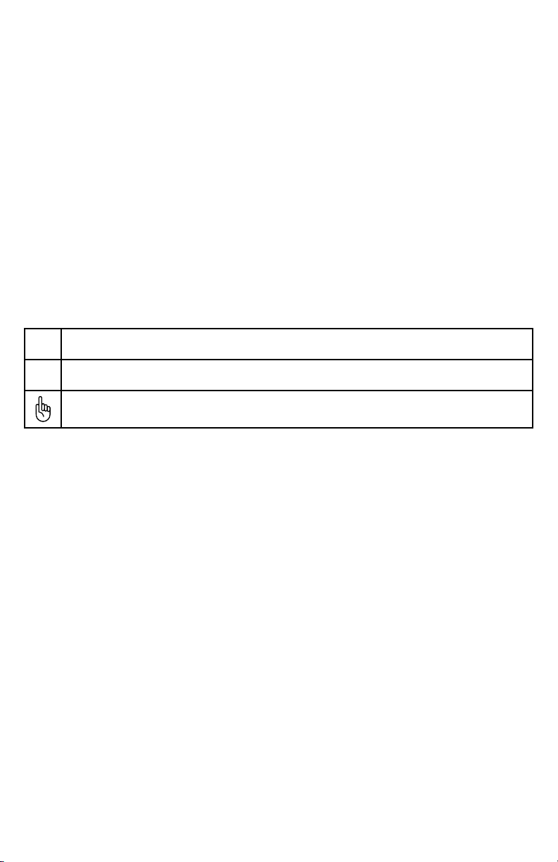
Figure 3-1: Clamping Black Lead to Ground Rod; Clamping Red Lead to Conductor
Clamp Red lead to target conductor sheath. See Figure 3-15.
Push T-5000 transmitter SFL key. Check measured fault resistance on transmitter display. See Figure 3-2 6.
Fault Severity Guide:
0-100 KΩ – Severe Fault
100 – 500 KΩ – Medium Fault
1 MΩ and above – Light Faults
Figure 3-2: Transmitter display in SFL mode
Select frequency - 9.8 KHz or 82 KHz, pressing the f button on the Transmitter keypad.7.
Use the R-5000 Utility Line Locator Receiver to Trace the Cable5.
Press the frequency softkey (Freq) on the receiver until the frequency selected on the transmitter is displayed. Trace and mark
the cable as you proceed towards the fault.
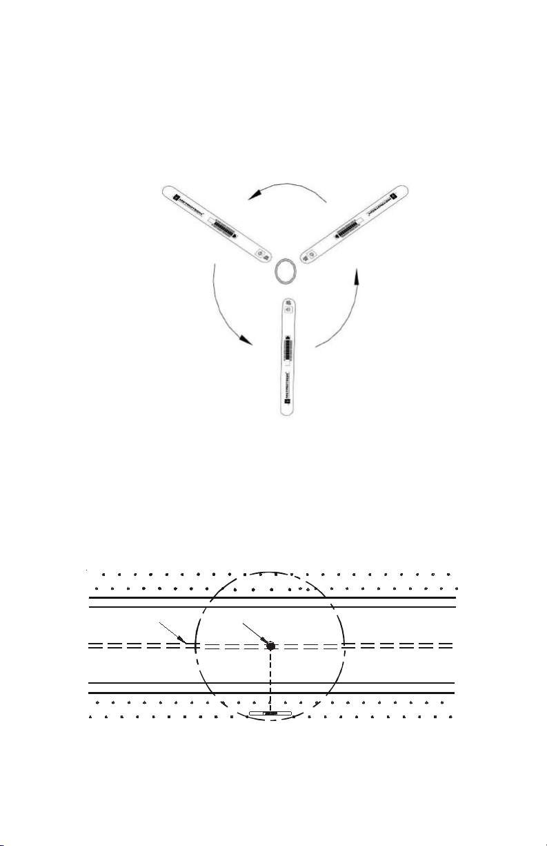
Synchronize the A-5000 A-Frame Receiver and Establish Reference Value of Fault 6.
(A-Frame receiver has a one-color band above each spike (Black or White)
Hold the A-5000 Receiver so the spike with the Black band is about two (2) steps away from the ground rod and the spike 1.
with the white band is in-line with the targeted cable. The A-5000 receiver must be placed as shown in Figure 3-3 for
synchronization and for unit to operate correctly. Push the A-5000 spikes firmly into the ground. Turn the A-5000 ON.
Wait until the arrow flashes.
6
Page 9

Figure 3-3: Positioning of A-5000 Receiver for Synchronization
Monitor bar-graph LCD display for arrow direction. If the arrow points AWAY from the ground rod, there is a fault.2.
If the arrow points TOWARDS the ground rod, there is no fault, and grounds and connections need to be rechecked.3.
The number of bars on the LCD indicates the potential gradient associated with the fault at the synchronization location.4.
The number of bars will decrease when you move away from the synchronization location and will increase when you get 5.
closer to the targeted fault. See Figure 3-4
Figure 3-4 : Locating the Cable Fault with A-5000 Receiver
Pinpoint the Fault7.
Keep the A-5000 parallel to the target cable.1.
Insert the A-5000 firmly in the ground every 10’ – 20’ (3 -6 m). Follow the arrow.2.
When the arrow changes direction, the fault may have been reached or passed.3.
Look at the number of bars activated as well as the “Actual” LCD reading and compare them to number of bars you
read at synchronization point as well as the “Reference” LCD reading. If the number of bars or the “Actual” and
“Reference” readings are similar to the number of bars at synchronization point, you have located the main fault.
7
Page 10
Backtrack. 4.
Insert the A-5000 every 2’ (.5 m) until the arrow changes direction again. 5.
Move the A-5000 across the cable until a slight movement causes the arrow to change direction. The fault is located at the 6.
center of the A-5000.
Check entire cable for multiple faults. If more faults are present, check the “Active” LCD number at each fault site and 7.
compare it to the “Reference” number. The higher the “Active” number the larger the fault.
A-5000 RECEIVER TECHNICAL SPECIFICATIONS
Linear A-Frames For Telecom Utilities:
Telecom faults, however, are typically higher resistance faults than power. The Linear A-frame A-5000 provides greater sensitivity
in the fault range of 100 KΩ – 10 MΩ to detect multiple faults in a cable.
A-Frame Receiver Controls And Indicators
See Figure 4-1 for the location of the Receiver controls described below:
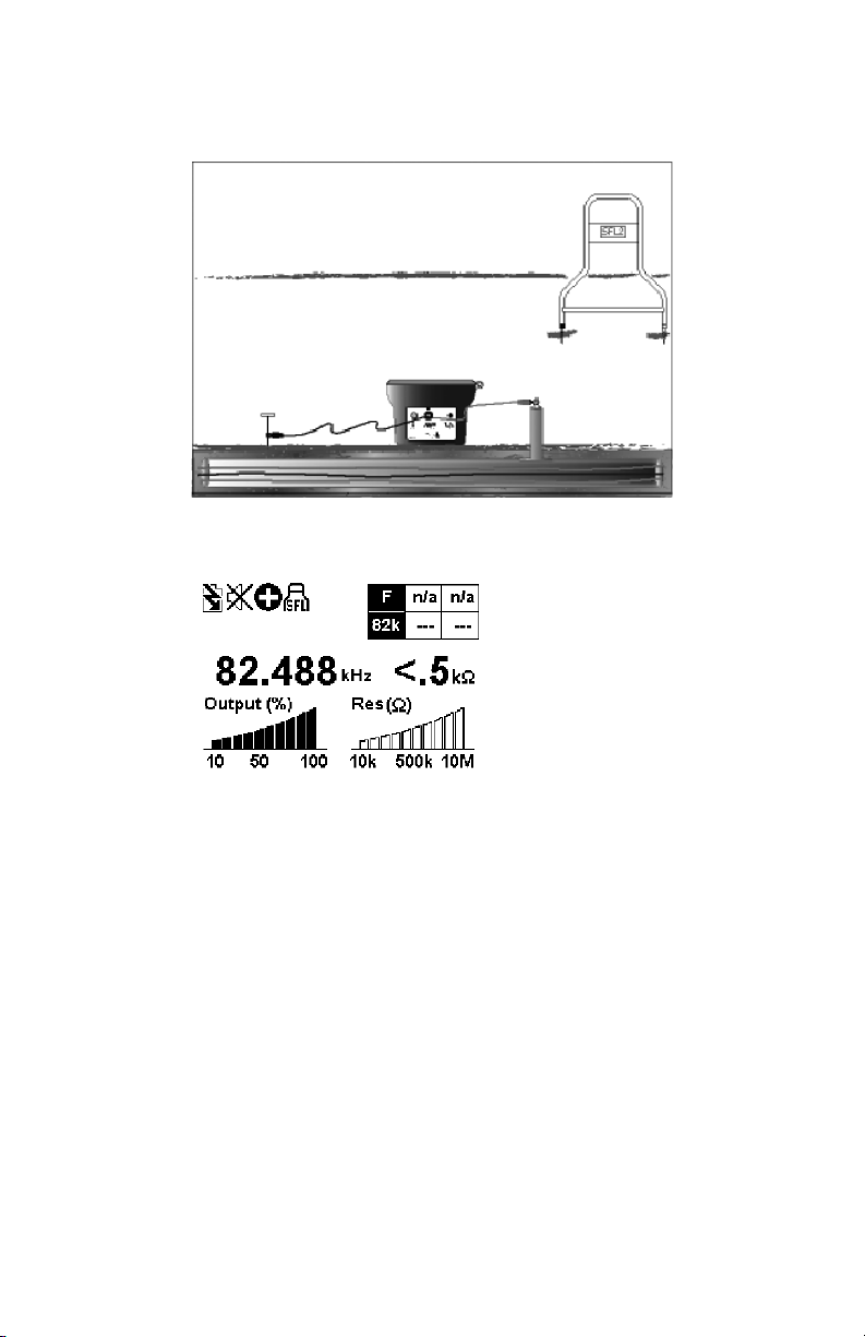
Figure 4-1: A-5000 Controls and Indicators
On/Off Button:
Push and release to turn ON. Push and release to turn OFF.
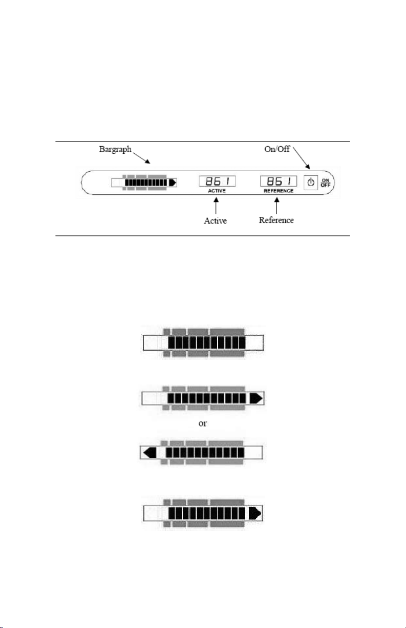
LCD Bar Graph Display:
The bar graph indicates three types of information:
Battery Status:
The solid bars indicate the battery level. If only one bar appears, replace the battery. The battery status is displayed for three
(3) seconds at Power ON.
Direction of Fault:
The flashing arrows will display the direction to the fault
Magnitude of Fault
The bar graph consists of twelve (12) bars with each bar representing the magnitude of the fault(s) as described below.
8
Page 11

Impedance (Ω) Linear Active/Reference Bars
450 828 12
1K 694 11-12
5K 413 11
10K 302 10-11
20K 222 10
30K 182 10
50K 139 9-10
100K 90 8-9
327K 45 7-8
1M 21 6-7
Additional A-Frame Receiver Features
Battery Access Plate
Located on the underside of Receiver control panel. Remove the two thumbscrews to release the plate. See Figure 9-1.
Conductive Pads
The A-Frame Receiver is shipped with two protective foam pads with large washers attached to the Receiver probes. These
pads are used for tracing on dry, hard surfaces. Protect and save these conductive pads and washers.
PRINCIPLES OF OPERATION
Functional Theory
Reviewing the basics of sheath fault locating is a valuable exercise before proceeding even for experienced users. This will
improve the chances of finding the fault and saving time.
Comparing electrical current to water flowing through a pipe applies extremely well to fault locating. Just like trying to find a
leak in a water pipe, you might seal off one end, pump water into the other, and look for water to appear near the leak. The
principles of sheath fault locating are identical. The cable equivalent of sealing off the pipe is to lift all connections at both
ends of the cable, creating a high resistance open condition. The “water” in this case is the current flowing through the cable
towards the fault. We look for the current “leak” with an A-Frame.
Both ends of the cable must be disconnected from ground.
The T-5000 transmitter applies a low frequency signal between an isolated conductor with an earth fault and another ground
point. This 4.8 Hz signal is induced into the ground from the fault location. The A-5000 Receiver contact probes detect this
signal pattern.
A typical hookup for locating a sheath fault, also called a shield-to-earth fault, is illustrated in Figure 5-1.
9
Page 12

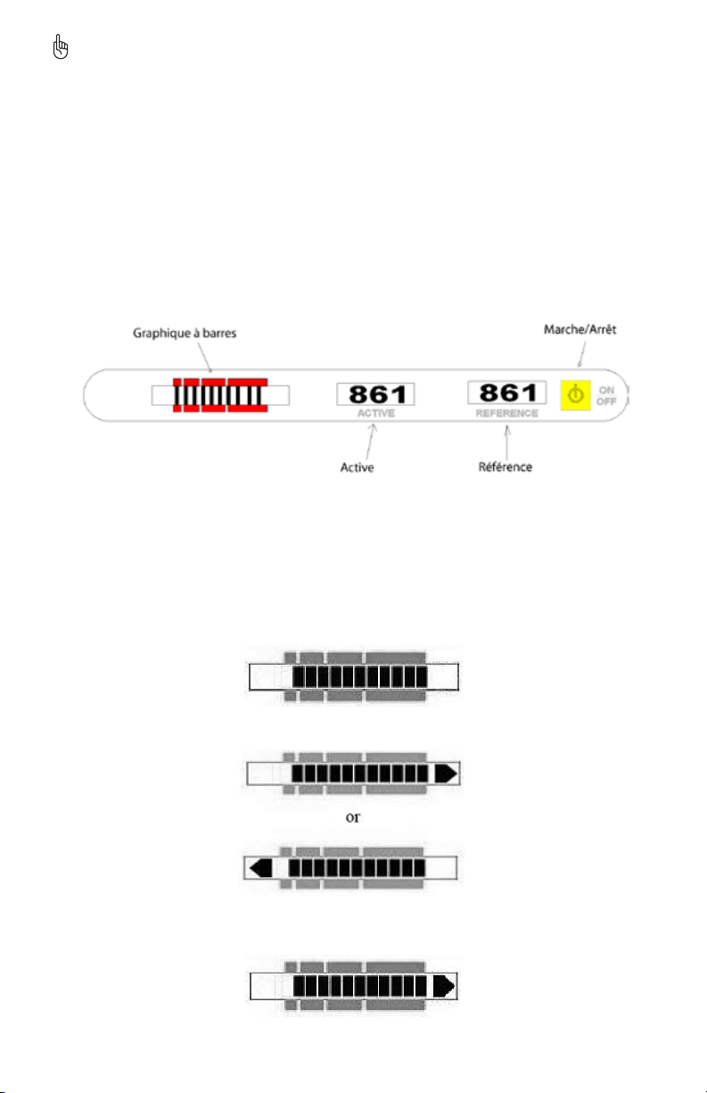
Figure 5-1: Typical T-5000 Transmitter Connection
1 Black Lead
2 Red Lead
3 Ground Rod
4 Fault
5 Faulty conductor open on both ends
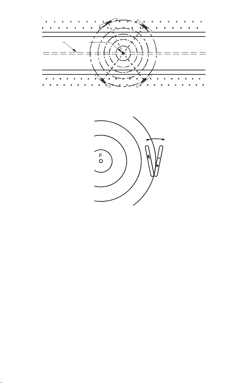
As current flows from the transmitter and through the fault, an earth voltage gradient field is created. Its center is at the
fault. This gradient field has a pattern as depicted in Figure 5-2, like pond water ripples when you throw a rock in it or
the rings of a tree stump.)
10
Page 13
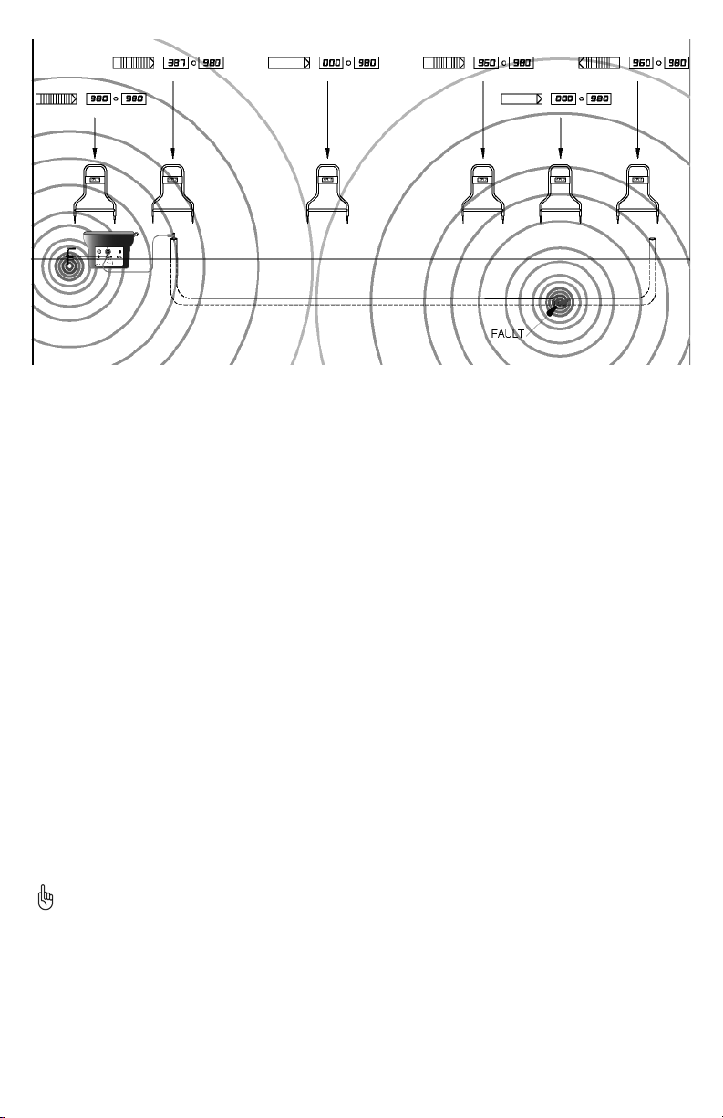
Figure 5-2: Signal Pattern Around Fault and Ground Point
The A-Frame Receiver compares the readings taken by the two probes and determines the direction and size of the fault.
Directional blinking arrows guide the operator to the exact source of the fault. The A-5000 bar graph and numerical active LCD
display indicates the relative distance to the fault and it is size.
Earth Voltage Gradient
Note in Figure 5-2 that the gradient pattern appears to be concentric circles near the fault. Properly interpreting this pattern is
the key to successful operation of the A-5000.
Equipotentials
The circles shown in Figure 5-2 represent lines of equal voltage. The boxes show what the bar graph will display with the A-5000
in different positions. Thus, if the A-5000 A-Frame were inserted so that both of the ground spikes were on the same circle,
there would be no difference in voltage between them. The bar graph will show zero, the arrows will become erratic and the
numerical active display will show a zero. One of these positions occurs when the fault is directly between the spikes.
This result can also occur midway between the ground spike and a fault and when the A-5000 is exactly perpendicular to the
fault. There is a return field around the transmitter ground spike. As you move toward the fault, the bars and the active
numerical number will decrease until you reach the midpoint between the fault and ground spikes. At the half waypoint
between the fault and ground spike, the signal strength is at it is absolute lowest. At this point the bar graph and active display
will show zero and the arrows become erratic.
To determine if you are midway between faults or directly over a fault, move the A-5000 further from the transmitter and
measure again. If the arrows tell you to continue in this direction, the zero point was a midpoint. If the arrows tell you to return
toward the transmitter, the zero point was a fault. As you continue, they will increase until you reach the fault.
Nearly 70% of the signal exists within the last 1/3 of the distance between the ground spike and the fault. The amount of signal
measured and displayed by the A-5000 is proportional to the number of field lines in Figure 5-2 between the A-5000 A-Frame
spikes. Thus, the maximum signal point occurs when one A-Frame spike is directly above the fault.
By probing around the ground point, a user can learn what to expect at the fault from the A-Frame bar graph response. As
shown in Figure 5-2, the signal pattern around the fault and ground point is identical (if there are no nearby conductors). This
means that the A-Frame will react the same way around the fault as at the ground point.
As you move toward the fault, the bars and the active numerical display will decrease until you reach the midpoint between the
fault and ground spike. As you continue, they will increase until you reach the fault.
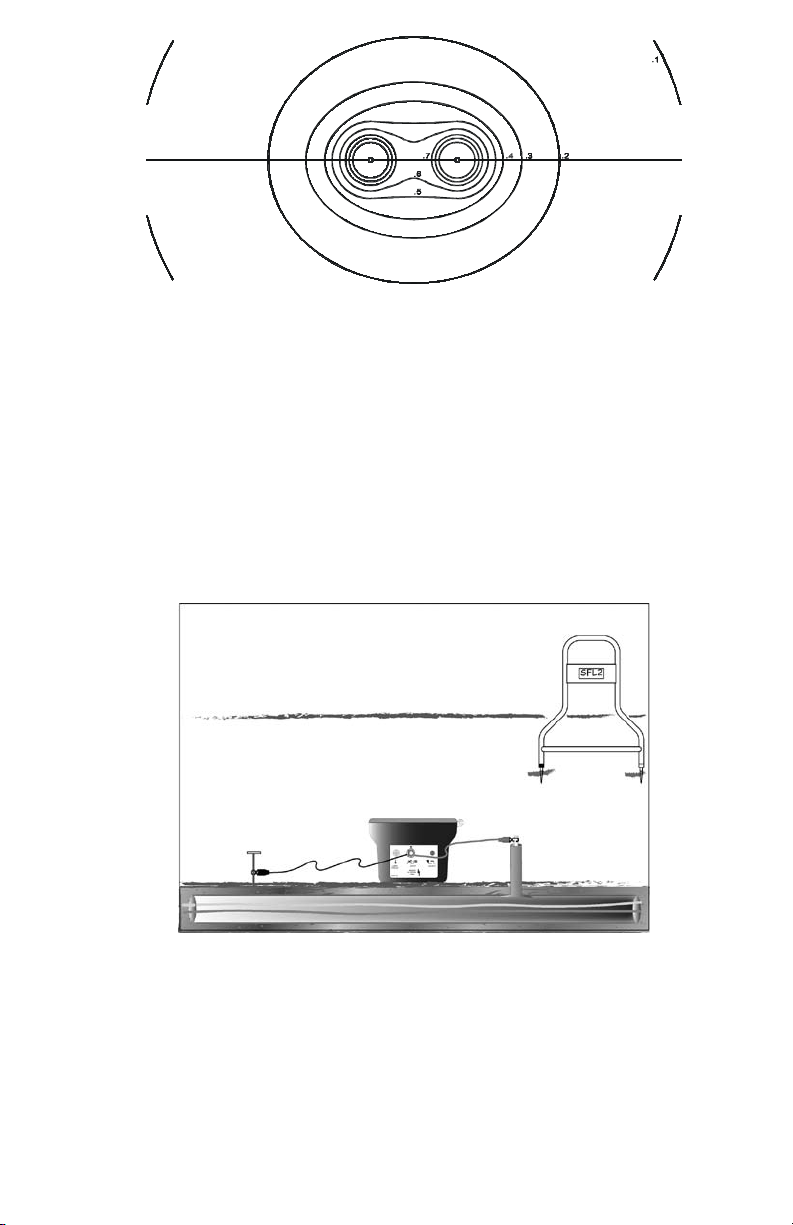
Multiple Fault Patterns
The signal pattern created by two faults in a line is depicted in Figure 5-3. The two faults are shown without the ground point.
Notice that from a distance the two faults will have the appearance of a single fault due to the equipotential circle around
them both. As you get closer, the individual faults become apparent. There is an area between two faults where the A-Frame
may give a false indication of another fault. This is caused by the two faults canceling each other. Errors can be avoided in this
situation by following the procedure described in Section 7.7.
We recommend that multiple faults be attacked one at a time. Whenever a fault is positively located, it should be repaired
before looking for the other faults.
11
Page 14
F1
F2
Figure 5-3: Multiple Fault Signal Patterns
Distortion Due to Adjacent Conductors
Whenever a non-insulated adjacent conductor lies between a fault and the ground return point, the return current tends to
concentrate on the conductor instead of flowing through the earth. This situation can shrink the signal pattern near the fault,
which would tend to reduce the detectable signal away from the fault. Possible distortion problems such as the described
situation can be avoided by first tracing the faulty conductor and looking for adjacent conductors prior to fault locating.
CALIBRATION TEST PROCEDURE
Perform this instrument test procedure on a lawn prior to field site use. If grass or dirt is not available, indoor carpeting may be
used.
Check the Batteries1.
Turn the T-5000 transmitter ON. The transmitter LCD will display the battery capacity level. Ensure the transmitter battery is
fully charged for optimal operation. Turn the transmitter OFF.
Turn the A-5000 Receiver ON. The solid bars indicate the battery level. If only one bar appears, replace the battery (1 each,
9V). The battery status is ON for 3 seconds at turn on.
Connect the Test Cables2.
Connect the Black and red connection leads to the transmitter OUTPUT JACK. See Figure 6-1.
Figure 6-1: Checkout Test Set-Up
Spread the Test Leads as Far Apart as Possible3.
Insert the ground spike and attach the Black cable. Insert a screwdriver into the ground and connect the Red cable to it,
creating a simulated fault.
This test can also be done by pushing the metal end of the clamps directly into the ground so that they make electrical
contact. When using a carpet in this checkout procedure connect test cable clamps directly to the carpet.
Push the SFL T-5000 transmitter button on the keypad4.
Wait for the SFL high-voltage output to be generated and observe the fault resistance transmitter display.
Synchronize the Receiver5.
Hold the A-5000 so that the black spike is closer to the ground connection. Push the A-Frame firmly into the ground.
Push the A-5000 Receiver On/Off Switch to ON6.
12
Page 15
The A-Frame Receiver will repeat its battery test. After the battery test, the arrow facing the simulated fault (Red test clamp)
flashes and a potential gradient number is shown on the Active and Reference LCD display.
Rotate the A-5000 180°7.
Note that the arrow now facing the red test clamp flashes. As the A-Frame is moved around the fault the arrow closest to the
simulated fault should flash.
OPERATION
Synchronize The A-Frame Receiver
By synchronizing, the A-5000 memorizes the phase of the transmitter signal. This allows it to recognize the reverse phase signal
coming from the fault and direct you to it.
Resynchronize the Receiver every 45 minutes to maintain optimum calibration. You may do this near the ground rod or
near a fault. At the ground rod, the black A-Frame spike must be nearer to the ground rod with the white spike facing
toward the fault. At a fault, the white A-Frame spike must be nearer to the fault.
Hold the A-5000 so that the black spike is closest to the ground rod.1.
Push the A-Frame spikes into the ground.2.
Switch the A-5000 Receiver ON. Wait until the arrow flashes on the bar graph.3.
If the arrow points away from the ground spike, there is a fault.4.
If the arrow points towards the ground spike, there is no fault. Recheck the grounds and connections if a fault is wrongly 5.
given. See Figure 7-1.
Figure 7-1: Synchronizing the A-5000
Confirm That A Fault Exists
Remove the A-Frame from the ground.1.
Rotate it 180° and re-insert it into the ground. The arrows should reverse directions and point away from the ground spike.2.
Trace The Cable With The R-5000 Receiver
The AT-5000 Utility Line Locator allows you to trace the line and search for the fault at the same time.
Check the R-5000 Receiver for cable tracing frequency. Aim the Receiver at the Red lead and cycle through the Receiver 1.
frequencies – 9.8 KHz or 82 KHz, to confirm that the selected tracing frequency is being received.
Trace and mark the cable as you proceed towards the fault.2.
Pinpoint The Fault
Keep the A-5000 parallel to the target cable1.
Insert the A-Frame every 10’ – 20’ (3 - 6 m). Follow the arrow and monitor the active number.2.
When locating with the A-5000, make sure that the probes are inserted well into the ground. A good physical ground 3.
connection is needed to receive strong signal.
13
Page 16
When the arrow changes direction, back track. Check the “Active” LCD number and compare it to the “Reference” LCD 4.
Pav ed Surfa ce
Cab le Fau lt
number. If both active and reference numbers have the same or similar value, you have found the major fault.
Insert the A-Frame every 2’ (50 cm) until the arrow changes direction again, then turn it 90 degrees. Check for obvious causes 5.
where a fault is suspected, such as recent excavation.
Continue to move the A-Frame across the cable until a slight movement causes the arrow to change directions. When this 6.
happens, the fault is located at the center of the A-Frame.
Verify The Fault
Move slightly off to one side of the cable.1.
Insert the A-Frame into the ground at various positions around the suspected fault site (like the hands of a clock).2.
The arrow should always point toward the fault.3.
Place the other spike in the ground at the fault site and repeat the process. The arrow should always point inward, toward 4.
the fault. See Figure 7-2.
Figure 7-2: Fault Confirmation
ADVANCED TECHNIQUES
Faults Under Inaccessible Surfaces
When the faults exist beneath a paved or other inaccessible area, the fault may be located using one of the following methods.
Perpendicular Method
Carefully trace the location of the faulty conductor. Hold the A-5000 parallel to the cable path. As you move away from the
ground rod the bar graph and the active number will gradually decrease until reaching the midpoint. It will then increase until
reaching the fault. When the A-Frame center passes a line perpendicular to the Sheath fault, the directional arrow indicators
will rapidly change positions and the bar graph and active number will drop to zero. See Figure 8-1.
Figure 8-1: Perpendicular Method
Triangulation Method
As shown in Figure 8-2, (the point where the signal strength is a minimum) if the A-5000 is positioned exactly on an
equipotential circle, a perpendicular line from the center of the A-Frame will pass through the fault. The intersection of any two
such perpendicular lines defines the fault location.
14
Page 17
Pav ed Surfa ce
Cab le Fau lt
Figure 8-2: Triangulation Method
To find an equipotential circle (see Figure 8-3) insert the A-Frame into the ground and pivot around one spike. Rotate the
A-Frame back and forth until the exact point is found where the flashing arrows change direction. The A-Frame is now on
an equipotential circle and is perpendicular to the fault. By marking this line and repeating the process with the A-Frame at
another nearby location, the two lines will intersect or cross at the fault.
Figure 8-3: Locating an Equipotential Circle
Faults Under Pavement
Faults under pavement or other slightly conductive surfaces can be found using the foam pads supplied with the unit. Saturate
the pads with water and insert the A-Frame spikes into the pads. Locate the fault as you normally would. Be sure to keep the
pads as moist as possible, but do not let the water form a continuous puddle between the pads as this will short out the signal.
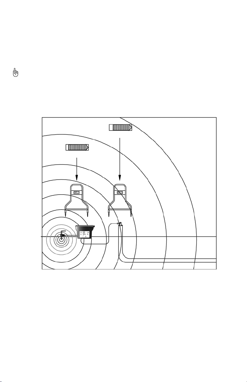
Long Distance Tracing
As the distance to the fault increases, the signal picked up by the A-5000 is proportionally reduced. This condition can lead to
problems if the signal levels are reduced to the point that they can no longer be detected by the A-Frame.
Whenever working with weak signals due to long distance faults (or other reasons), increased sensitivity can be obtained by
extending the distance between the A-Frame spikes using the extension cable. This extension method can be applied to any of
the previously discussed methods including the conductive foam pads. When working with very long distances, as in fiber optic
runs, the sensitivity can be increased even further using a longer insulated wire to extend the A-Frame span. See Figure 8-4.
15
Page 18
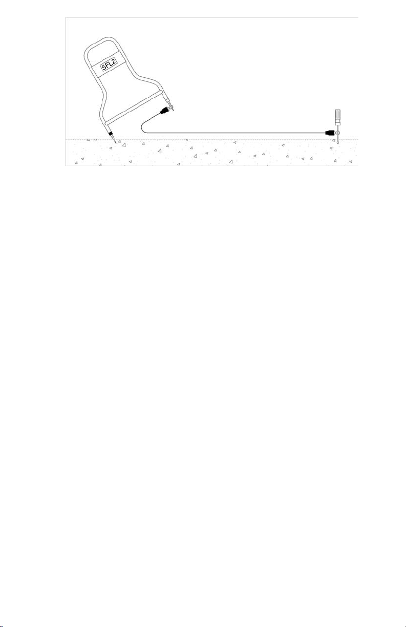
Figure 8-4: Fault Location Using Extension Cable for Increased Sensitivity
High And Low Impedance Faults
Before beginning a fault search it is a good idea to know the severity of the fault. This is measured in terms of its resistance
or impedance to ground. Faults where the ground is wet and/or a very large piece of the insulation is missing are found at the
low end of the range (<500 Ohms). Conditions where the ground is very dry and/or the actual fault is a small pinhole where the
conductor has a very small ground contact area are found at the high end of the fault range (>1-3 MΩ).
A low impedance fault is the easiest to find since there is more signal to detect.
Generally, the more bars and a higher number displayed at synchronization, the larger the fault.
A high impedance fault is more difficult to locate. Characteristically, the A-5000 Receiver may not detect the signal after moving
a short distance away from the ground point. The higher the impedance of the fault, the closer you must be to detect it.
Example
If the A-Frame only reliably points away from the ground connection within 20’ (3 m), then the A-frame will only detect the
fault within about 20’ (3 m). Outside this distance the signal is too weak to reliably detect.
For this reason we highly recommend tracing and marking the line before searching out high impedance faults.
Multiple Faults
Locating multiple faults is the most difficult and confusing fault situation. It is especially important in this case to accurately
trace the faulty conductor before beginning the fault search. Stay exactly above the line if possible and verify each suspected
fault by monitoring the active number to see which fault has the higher number. Remember that a very strong or low
impedance fault will mask the detection of a weak or high impedance fault. The safest and best way to find multiple faults is to
repair each fault as it is positively identified and then continue the search. See Figure 5-3.
MAINTENANCE
A-5000 Receiver Battery Replacement.
Loosen the two thumbscrews located on the underside of the Receiver housing. Gently pull out battery door. Be careful not
to pull on the battery wires. Remove battery from battery holder and disconnect battery. Reverse procedure for installing new
battery.
16
Page 19
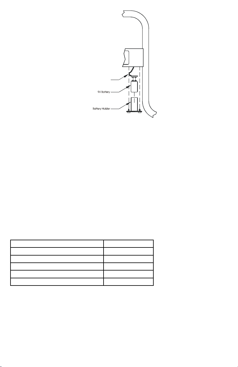
C onne c tor
Figure 9-1: A-5000 Receiver Battery Replacement
TECHNICAL SPECIFICATIONS
Frequency: 4.8 Hz Crystal Controlled
Input Sensitivity: 5 MV
Sensitivity Control: Automatic
Active/Reference Signal Sensitivity Logarithmic: 0 − 120
Linear: 0 − 999
Battery: 9 V NEDA 1604 or equivalent
Battery Life: 100 hr. continuous use
Battery Test: Automatic at power ON for 3 sec.
Weight: 4.4 lb (2.0 kg)
Dimensions: 32” H x 22” W x 1” D
(81 cm H x 56 cm W x 2.5 cm D)
Operational Temp: -4°F − +120°F
(-20°C − +50°C)
APPENDIX
APWA Marking Colors
The following color markings have been established by the American Public Works Association (APWA):
Conductor Color
Electric power lines, cables, or conduits Red
Communication lines, cables, Conduits, CATV Orange
Gas, oil, petroleum, or other gaseous materials Yellow
Sewers, storm and sanitary, drain lines Green
Water, irrigation, or slurry lines Blue
If you have any questions regarding marking requirements or procedures in the United States, please call your local One Call
Center. International customers: please check with your local regulatory authorities or utility companies required color markings
may vary between different countries.
17
Page 20

18
Page 21

A-5000
Détecteur de défauts
de gainage
Mode d’emploi
A5000_Rev002
© 2009 Amprobe Test Tools.
Tous droits réservés.
Français
19
Page 22

Limites de garantie et de responsabilité
Amprobe garantit l’absence de vices de matériaux et de fabrication de ce produit pendant une période d’un an prenant effet à
la date d’achat. Cette garantie ne s’applique pas aux fusibles, aux piles jetables ni à tout produit mal utilisé, modifié, contaminé,
négligé ou endommagé par accident ou soumis à des conditions anormales d’utilisation et de manipulation. L’obligation de
garantie d’Amprobe est limitée, au choix d’Amprobe, au remboursement du prix d’achat ou à la réparation/remplacement
gratuit d’un produit défectueux. Les revendeurs n’ont pas l’autorisation de prolonger toute autre garantie au nom d’Amprobe.
Pour bénéficier de la garantie, renvoyez le produit accompagné d’un justificatif d’achat auprès d’un centre de services agréé
par Amprobe Test Tools ou d’un distributeur ou d’un revendeur Amprobe. Voir la section Réparation pour tous les détails.
La présente garantie est votre recours exclusif. Toutes autres garanties, explicites, implicites ou statutaires, notamment le cas
échéant, les garanties de qualité marchande ou d’adaptation à un objectif particulier sont exclues par les présentes. Amprobe,
la société mère ou ses filiales ne peuvent en aucun cas être tenues responsables des dommages particuliers, indirects, accidentels
ou consécutifs, ni d’aucuns dégâts ou pertes de données, sur une base contractuelle, extra-contractuelle ou autre. Etant donné
que certaines juridictions n’admettent pas les limitations d’une condition de garantie implicite ou l’exclusion ou la limitation de
dégâts accidentels ou consécutifs, il se peut que les limitations et les exclusions de cette garantie ne s’appliquent pas à votre cas.
Réparation
Tous les outils de test renvoyés pour un étalonnage ou une réparation couverte ou non par la garantie doivent être accompagnés
des éléments suivants : nom, raison sociale, adresse, numéro de téléphone et justificatif d’achat. Ajoutez également une brève
description du problème ou du service demandé et incluez les cordons de mesure avec l’appareil. Les frais de remplacement ou
de réparation hors garantie doivent être acquittés par chèque, mandat, carte de crédit avec date d’expiration, ou par bon de
commande payable à l’ordre de Amprobe
Remplacements et réparations sous garantie – Tous pays
Veuillez lire la déclaration de garantie et vérifier la pile avant de demander une réparation. Pendant la période de garantie,
tout outil de test défectueux peut être renvoyé auprès de votre distributeur Amprobe
un produit identique ou similaire. Consultez la section « Where to Buy » sur le site www.amprobe.com pour obtenir la liste
des distributeurs dans votre région. Au Canada et aux Etats-Unis, les appareils devant être remplacés ou réparés sous garantie
peuvent également être envoyés dans un centre de services Amprobe
Remplacements et réparations hors garantie – Canada et Etats-Unis
Les appareils à réparer hors garantie au Canada et aux Etats-Unis doivent être envoyés dans un centre de services Amprobe® Test
Tools. Appelez Amprobe
remplacement ou de réparation.
®
Test Tools ou renseignez-vous auprès de votre lieu d’achat pour connaître les tarifs en vigueur de
Aux Etat s-Unis Au Canada
Amprobe Test Tools Amprobe Test Tools
Everett, WA 98203 Mississauga, ON L4Z 1X9
Tel: 888-993-5853 Tel: 905-890-7600
Fax: 425 -4 46-6390 Fax: 905-890-6866
Remplacements et réparations hors garantie – Europe
Les appareils européens non couverts par la garantie peuvent être remplacés par votre distributeur Amprobe
une somme nominale. Consultez la section « Where to Buy » sur le site www.amprobe.com pour obtenir la liste des distributeurs
dans votre région.
Adresse postale européenne*
Amprobe® Test Tools Europe
Beha-Amprobe GmbH
In den Engematten 14
79286 Glottertal, Germany
Tel.: +49 (0) 7684 8009 - 0
*(Réservée à la correspondance – Aucune réparation ou remplacement n’est possible à cette adresse. Nos clients européens
doivent contacter leur distributeur.)
®
Test Tools.
®
Test Tools pour être échangé contre
®
Test Tools (voir page suivante pour les adresses).
®
Test Tools pour
20
Page 23

➊ Boutons marche/arrêt
Indicateur de référence
➋
Indicateur actif
➌
Indicateur de graphique à barres
➍
Piquets du module triangulaire
➎
21
Page 24

Détecteur de défauts de gainage
A-5000
TABLE DES MATIÈRES
Introduction ................................................................................................................................................................................................ 5
Informations générales et sécurité ........................................................................................................................................................... 5
Symboles utilisés dans ce manuel ........................................................................................................................................................5
Consignes de sécurité ...........................................................................................................................................................................5
Guide de démarrage du détecteur de défauts de gainage A-5000 pour utilisateur chevronné .......................................................... 5
Caractéristiques techniques du récepteur A-5000 ................................................................................................................................... 8
Modules triangulaires linéaires pour compagnies de télécommunications ...................................................................................... 8
Indicateurs et commandes du récepteur du module triangulaire ..................................................................................................... 8
Principes de fonctionnement .................................................................................................................................................................... 9
Théorie fonctionnelle ........................................................................................................................................................................... 9
Procédure du test d’étalonnage .............................................................................................................................................................. 12
Fonctionnement ....................................................................................................................................................................................... 13
Synchroniser le récepteur du module triangulaire ........................................................................................................................... 13
Confirmer la présence d’un défaut .................................................................................................................................................... 13
Dépister le câble avec le récepteur R-5000 ....................................................................................................................................... 13
Localiser le défaut ............................................................................................................................................................................... 14
Vérifier le défaut ................................................................................................................................................................................ 14
Techniques avancées ................................................................................................................................................................................ 14
Défauts sous surfaces inaccessibles .................................................................................................................................................... 14
Défauts sous pavage ........................................................................................................................................................................... 15
Dépistage sur longues distances ........................................................................................................................................................ 16
Défauts d’impédance faible et élevée ............................................................................................................................................... 16
Défauts multiples ................................................................................................................................................................................ 16
Entretien ................................................................................................................................................................................................... 16
Remplacement des piles du récepteur A-5000. ................................................................................................................................. 16
Caractéristiques techniques ..................................................................................................................................................................... 17
Annexe ...................................................................................................................................................................................................... 17
Couleurs de marquage APWA ........................................................................................................................................................... 17
22
Page 25
INTRODUCTION
Le détecteur utilitaire Amprobe AT-5000 avec l’option de détection des défauts de gainage (SFL) est conçu pour détecter et
localiser les défauts des gaines et des conducteurs qui sont en contact direct avec la terre.
L’AT-5000 avec option A-5000 (SFL) offre ces fonctionnalités uniques :
Mesure du niveau de défaut au niveau de l’émetteur•
Détection des défauts et dépistage de ligne simultanés•
Le graphique à barres LCD représentant la puissance des signaux du module triangulaire permet de juger la proximité aux •
défauts, en comparant les multiples défauts et en détectant les piqûres et les « arborescences » d’un câble d’alimentation
Détection des défauts de résistance faible et élevée•
Vérification automatique des piles et avertissement de piles faibles•
Module triangulaire non-polarisé•
Fonctionnement d’une seule main. Inutile de transporter un récepteur R-5000 et un module triangulaire pendant la •
localisation des défauts
Voltmètre et ohmmètre SFL actifs dans l’émetteur•
INFORMATIONS GÉNÉRALES ET SÉCURITÉ
Ce manuel contient des conseils de base pour l’installation et le fonctionnement des détecteurs de défauts de gainage et
de lignes d’utilité publique Amprobe ainsi que des accessoires qui les accompagnent. Le fabricant n’est pas responsable des
dommages matériels ou des lésions personnelles qui surviendraient en raison du non-respect des instructions et des conseils
de sécurité figurant dans ce manuel. Ce manuel doit donc être fourni afin de pouvoir être consulté par toutes les personnes
associées aux équipements de détection des défauts de gainage et de lignes d’utilité publique.
Symboles utilisés dans ce manuel
Les instructions importantes concernant la protection du personnel et des équipements ainsi que la sécurité technique sont
identifiées par l’un des symboles suivants dans ce document :
Indique une situation potentiellement dangereuse qui, si elle n’est pas évitée, est susceptible d’entraîner des dégâts
matériels ou des blessures légères et modérées.
Indique une situation potentiellement dangereuse qui, si elle n’est pas évitée, est susceptible d’entraîner des
blessures graves, voire mortelles.
Les remarques contiennent d’importantes informations et des conseils utiles sur le fonctionnement de l’équipement.
Le non-respect de ces remarques pourrait entraîner des résultats incorrects.
Personnels autorisés
Les détecteurs de défaut de gainage et de lignes d’utilité publique Amprobe sont destinés aux entrepreneurs et aux spécialistes
des compagnies d’utilité publique.
Réparation et entretien
Les réparations et les interventions doivent être effectuées par Amprobe.
Consignes de sécurité
Pratiques de sécurité à observer
Familiarisez-vous avec toutes les pratiques de sécurité requises par la compagnie d’utilité publique concernée ou par le
propriétaire des installations avant de pénétrer dans la zone d’accès ou de brancher un émetteur Amprobe.
Assurez-vous que la ligne est hors tension et hors service, AVANT de brancher l’émetteur directement à un conducteur.
N’établissez JAMAIS de branchement direct à un câble d’alimentation sous tension.
Suivez les procédures de sécurité appropriées pour éviter les risques de blessure en utilisant une pince sur des lignes de
commande ou d’électricité sous tension.
Faites particulièrement attention en utilisant un détecteur dans des zones à trafic élevé.
Application prévue
Le fonctionnement n’est véritablement sécurisé que si l’équipement est utilisé dans le but prévu. L’utilisation de l’équipement
dans d’autres buts risque de provoquer des dégâts ou de poser des dangers aux personnes.
Les limites décrites dans la fiche technique ne doivent pas être dépassées.
GUIDE DE DÉMARRAGE DU DÉTECTEUR DE DÉFAUTS DE GAINAGE A-5000 POUR UTILISATEUR CHEVRONNÉ
Vérifiez les piles avant le départ sur le terrain 1.
Vérifiez le niveau des piles de l’émetteur, du récepteur et du module triangulaire en démarrant chaque instrument.
L’utilisation optimale de la fonction SFL de l’émetteur exige de charger les piles à fond avant l’utilisation sur le terrain. Amprobe
recommande de charger à fond les piles avant de localiser les défauts.
Remplacez les piles ou rechargez-les si nécessaire. Eteignez les instruments.
Veillez à mettre tous les conducteurs hors tension2.
Débranchez les fils de terre3.
Débranchez les fils de terre (de tous les conducteurs du circuit) à chaque extrémité de la section câblée présentant un défaut.
AVERTISSEMENT Le JACK DE SORTIE (OUTPUT) externe produit une haute tension lorsque l’émetteur T-5000 est allumé. Ne
touchez pas au jack ! Il présente un danger d’électrocution !
23
Page 26
Connectez l’émetteur au conducteur : vérifiez la résistance de défaut4.
1. Vérifiez que l’émetteur T-5000 est hors tension.
2. Branchez les cordons conducteurs noir et rouge à l’émetteur.
3. Etirez le cordon noir à 180° en l’éloignant du conducteur.
4. Enfoncez la tige dans la terre et fixez le cordon noir sur la tige de terre. Etablissez la meilleure mise à la terre possible.
Voir Figure 3-1
Figure 3-1 : Serrage du cordon noir à la tige de terre ; serrage du cordon rouge au conducteur
Serrez le cordon rouge sur la gaine du conducteur cible. Voir Figure 3-15.
Enfoncez la touche SFL de l’émetteur T-5000. Vérifiez la résistance de défaut mesurée sur l’afficheur de l’émetteur. Voir 6.
Figure 3-2
Guide de gravité des défauts :
0 à 100 KΩ : Défaut grave
100 à 500 KΩ : Défaut intermédiaire
1 MΩ et au-delà : Défauts légers
Figure 3-2 : Afficheur de l’émetteur en mode SFL
Sélectionnez la fréquence - 9,8 KHz ou 82 KHz, en appuyant sur le bouton f du clavier de l’émetteur.7.
5. Utilisez le récepteur du détecteur de lignes d’utilité publique R-5000 pour le dépistage du câble
Appuyez sur la touche programmable de fréquence (Freq) du récepteur jusqu’à l’apparition de la fréquence sélectionnée.
Dépistez et repérez le trajet du câble en progressant vers le défaut.
6. Synchronisez le récepteur du module triangulaire A-5000 et établissez la valeur de référence du défaut
(le récepteur du module triangulaire montre une bande monochrome au-dessus de chaque piquet (noire ou blanche)
1. Maintenez le récepteur A-5000 de façon à positionner le piquet associé à la bande noire à deux (2) pas de la tige de terre
et à aligner le piquet avec la bande blanche avec le câble ciblé. Le récepteur A-5000 doit être placé conformément à la
figure 3-3 pour la synchronisation et le bon fonctionnement de l’appareil. Enfoncez les piquets du A-5000 solidement dans
la terre. Mettez l’A-5000 sous tension. Attendez le clignotement de la flèche.
24
Page 27

Figure 3-3 : Positionnement du récepteur A-5000 pour la synchronisation
2. Consultez l’affichage incrémental LCD pour la direction de la flèche. Si celle-ci pointe dans la DIRECTION OPPOSEE à la tige
de terre, cela indique la présence d’un défaut.
3. Aucun défaut n’est présent si la flèche pointe EN DIRECTION de la tige de terre. Dans ce cas, il faut revérifier les
branchements et les prises de terre.
4. Le nombre de barres sur l’afficheur LCD indique le gradient potentiel associé au défaut au point de synchronisation.
5. Le nombre de barres diminue lorsque l’opérateur s’éloigne du point de synchronisation et augmente quand l’opérateur se
rapproche du défaut ciblé. Voir Figure 3-4
Figure 3-4 : Localisation du défaut du câble avec le récepteur A-5000
7. Localiser le défaut
1. Tenez l’A-5000 parallèlement au trajet du câble ciblé.
2. Insérez l’A-5000 solidement dans le sol tous les 3 à 6 mètres (10 à 20 pieds). Suivez la flèche.
3. Le défaut a probablement été dépassé ou ignoré si la flèche change de direction.
25
Page 28
Relevez le nombre de barres activées et la valeur LCD « active », et comparez-les avec le nombre de barres relevées au
point de synchronisation et avec la valeur LCD de « référence ». Le défaut principal a été localisé si le nombre de barres
ou les valeurs « actives » et de « référence » sont similaires au nombre de barres relevé au point de synchronisation.
4. Revenez en arrière.
5. Insérez l’A-5000 tous les 0,5 mètre (2 pieds) jusqu’au nouveau changement de direction de la flèche.
6. Déplacez l’A-5000 le long du câble jusqu’à ce qu’un léger mouvement entraîne un changement de direction de la flèche.
Le défaut est situé au centre de l’A-5000.
7. Vérifiez tout le trajet du câble pour détecter des défauts multiples. En présence de plusieurs défauts, relevez la valeur LCD
« active » à chaque point de défaut et comparez-la à la valeur de « référence ». Plus la valeur « active » est élevée, plus le
défaut est important.
CARACTÉRISTIQUES TECHNIQUES DU RÉCEPTEUR A-5000
Modules triangulaires linéaires pour compagnies de télécommunications :
Les défauts des lignes de télécommunications affichent toutefois des résistances typiquement plus élevées que les défauts des
lignes d’alimentation. Le module triangulaire linéaire A-5000 assure une plus grande sensibilité dans la gamme des défauts de
100 KΩ à 10 MΩ pour détecter plusieurs défauts dans un câble.
Indicateurs et commandes du récepteur du module triangulaire
Reportez-vous à la figure 4-1 pour repérer les commandes du récepteur décrites ci-dessous :
Figure 4-1 : Indicateurs et commandes de l’A-5000
Bouton marche/arrêt :
Enfoncez et relâchez le bouton pour mettre l’appareil sous tension. Enfoncez et relâchez le bouton pour mettre l’appareil
hors tension.
Affichage incrémental LCD :
Le graphique à barres indique trois types d’informations :
Etat des piles :
Les barres pleines indiquent le niveau des piles. Remplacez les piles si une seule barre est affichée. L’état des piles s’affiche
pendant trois (3) secondes à la mise sous tension.
Direction du défaut :
Les flèches clignotantes affichent la direction vers le défaut
Amplitude du défaut
Le graphique à barres comprend douze (12) barres, chaque barre représentant l’amplitude du ou des défauts décrits
ci-dessous.
26
Page 29

Impédance (Ω) Référence/active linéaire Barres
450 828 12
1K 694 11-12
5K 413 11
10K 302 10-11
20K 222 10
30K 182 10
50K 139 9-10
100K 90 8-9
327K 45 7-8
1M 21 6-7
Fonctionnalités d’un récepteur de module triangulaire supplémentaire
Plaque d’accès aux piles
Située sous le panneau de commande du récepteur. Retirez les deux vis de serrage pour libérer la plaque. Voir Figure 9-1
Plots conducteurs
Le récepteur de module triangulaire est livré avec deux plots de protection en mousse munis de grandes rondelles fixées aux
sondes du récepteur. Ces plots sont utilisés pour le dépistage sur les surfaces rigides et sèches. Protégez et conservez ces plots
conducteurs et ces rondelles.
PRINCIPES DE FONCTIONNEMENT
Théorie fonctionnelle
Il est très important d’examiner avec soin les principes fondamentaux de la localisation des défauts de gainage avant de
démarrer, même pour les utilisateurs expérimentés. Cet examen optimise les chances de l’opérateur de détecter les défauts et
permet de gagner du temps.
Il est tout à fait approprié de comparer la circulation du courant électrique à de l’eau qui s’écoulerait dans une conduite lors de
la détection d’un défaut. Lorsque vous recherchez une fuite dans une conduite d’eau, vous pouvez boucher une extrémité du
tuyau, pomper l’eau dans l’autre, et guetter l’apparition de l’humidité près de la fuite. Il en va de même quand on recherche
les défauts de gainage. Sur un câble, l’étanchéification de la conduite d’eau revient à débrancher tous les branchements aux
deux extrémités du câble, en créant une condition de coupure à haute résistance. Dans ce cas, l’« eau » correspond au courant
circulant dans le câble en direction du défaut. Nous recherchons la « fuite » de courant avec un module triangulaire.
Les deux extrémités du câble doivent être débranchées de la terre.
L’émetteur T-5000 applique un signal à faible fréquence entre un conducteur isolé avec un défaut de terre et un autre point à
la terre. Ce signal de 4,8 Hz est induit dans la terre depuis l’emplacement du défaut. Les sondes de contact du récepteur A-5000
détectent ce profil de signal.
Le branchement typique pour dépister un défaut de gainage, appelé aussi défaut de gainage à la terre, est illustré dans la
figure 5-1.
27
Page 30
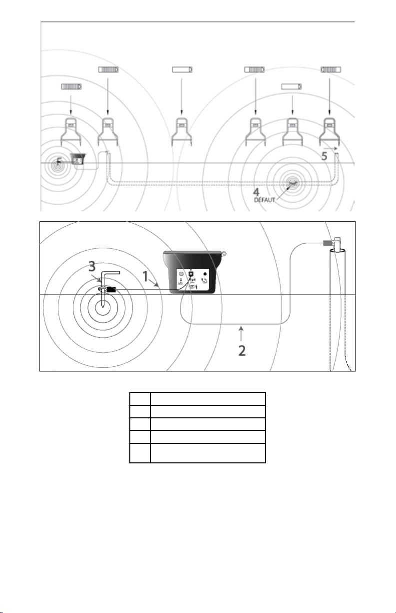
Figure 5-1 : Branchement typique de l’émetteur T-5000
1 Cordon noir
2 Cordon rouge
3 Tige de terre
4 Défaut
Conducteur défectueux coupé aux
5
deux extrémités
Un champ de gradient de tension à la terre est créé à mesure que le courant circule de l’émetteur jusqu’au défaut. Son
centre est au niveau du défaut. Ce champ de gradient montre le motif illustré dans la figure 5-2, évoquant les cercles
concentriques créés à la surface d’une mare par le jet d’une pierre ou les cercles de croissance d’un arbre.
28
Page 31

Figure 5-2 : Motif des signaux à proximité d’un défaut et d’un point de terre
Le récepteur du module triangulaire compare les valeurs relevées par les deux sondes et détermine la direction et la taille du
défaut. Les flèches de clignotement directionnelles guident l’opérateur vers la source exacte du défaut. Le graphique à barres de
l’A-5000 et la valeur numérique active sur l’écran LCD indiquent la distance relative au défaut et sa taille.
Gradient de tension à la terre
Notez dans la figure 5-2 que le profil de gradient affiche des cercles concentriques près du défaut. Une bonne interprétation de
ce motif est fondamentale pour la bonne utilisation de l’A-5000.
Equipotentiels
Les cercles illustrés dans la figure 5-2 représentent les lignes de tensions égales. Les cases montrent la configuration des barres
incrémentales lorsque l’A-5000 occupe différentes positions. Ainsi, si le module triangulaire A-5000 était inséré de façon à
positionner les deux piquets de terre sur le même cercle, on n’observerait aucune différence de tension entre les deux piquets.
Le graphique à barres indique zéro, les flèches s’affolent et l’affichage actif numérique indique zéro. L’une de ces positions se
produit quand le défaut est directement situé entre les piquets.
Ce résultat peut également être observé à mi-trajet entre le piquet de terre et le défaut, et lorsque l’A-5000 est exactement
perpendiculaire au défaut. On observe un champ inverse autour du piquet de terre de l’émetteur. Les barres et la valeur
numérique active diminuent à mesure que l’opérateur se rapproche du défaut, jusqu’à ce qu’il arrive à mi-trajet entre le défaut
et les piquets de terre. A mi-trajet entre le défaut et le piquet de terre, l’intensité du signal présente la force absolue la plus
faible. A ce stade, le graphique à barres et la valeur active affichée indiquent zéro et les flèches s’affolent.
Pour déterminer s’il se trouve à mi-trajet entre les défauts ou directement sur un défaut, l’opérateur doit éloigner l’A-5000 de
l’émetteur et recommencer la mesure. Si les flèches lui indiquent de continuer dans cette direction, le point zéro se trouvait à mitrajet. Si les flèches lui indiquent de revenir vers l’émetteur, le point zéro était un défaut. Les flèches incrémentales continuent
d’augmenter jusqu’à ce que l’opérateur atteigne le défaut.
Le signal est présent à environ 70 % dans le dernier tiers de la distance entre le piquet de terre et le défaut. La quantité de signal
mesurée et affichée par l’A-5000 est proportionnelle au nombre de lignes du champ (voir Figure 5-2) entre les piquets du module
triangulaire A-5000. Ainsi, le point du signal maximum intervient lorsqu’un piquet du module triangulaire est directement audessus du défaut.
En sondant à proximité du point de terre, l’utilisateur peut anticiper ce qu’il trouvera au point du défaut grâce à la réponse du
graphique incrémental du module triangulaire. Comme l’illustre la figure 5-2, le motif du signal est identique à proximité du
défaut et du point de terre (s’il n’y a pas de conducteurs à proximité). Cela signifie que le module triangulaire réagit de la même
façon à proximité du défaut et du point de terre.
Les barres et la valeur numérique active diminuent quand l’opérateur se rapproche du défaut, jusqu’à ce qu’il arrive à mi-trajet
entre le défaut et le piquet de terre. Les barres continuent d’augmenter jusqu’à ce que l’opérateur atteigne le défaut.
Configurations à plusieurs défauts
Le profil de signal créés par deux défauts dans une ligne est illustré dans la figure 5-3. Les deux défauts sont illustrés sans le point
de terre. Remarquez qu’à une certaine distance ces deux défauts ont l’aspect d’un seul défaut en raison du cercle équipotentiel
qui les entoure. Chaque défaut se distingue l’un de l’autre à mesure que l’on se rapproche. Dans la zone entre les deux défauts,
le module triangulaire est susceptible de fournir une indication erronée concernant un autre défaut. Cela est dû au fait que les
deux défauts s’annulent mutuellement. Ces erreurs peuvent être évitées en respectant la procédure décrite dans la section 7.7.
Nous recommandons de prendre en compte chaque défaut l’un après l’autre. Après avoir localisé positivement un défaut,
vous devez le réparer avant de rechercher les autres défauts.
29
Page 32

F1
F2
Figure 5-3 : Motifs de signaux de plusieurs défauts
Distorsion due à des conducteurs adjacents
En présence d’un conducteur adjacent non-isolé entre un défaut et le point de retour à la terre, le courant inverse tend à se
concentrer sur le conducteur au lieu de se diriger dans la terre. Dans ce cas, le motif du signal près du défaut peut se rétrécir, ce
qui risque de réduire le signal détectable lorsqu’on s’éloigne du défaut. Les problèmes de distorsion éventuels décrits ici peuvent
être évités en dépistant d’abord le conducteur défectueux et en recherchant les conducteurs adjacents avant de localiser le défaut.
PROCÉDURE DU TEST D’ÉTALONNAGE
Effectuez cette procédure de test sur l’instrument sur une pelouse avant d’emporter l’appareil sur le terrain. En l’absence d’herbe
ou de terreau, un sol recouvert de moquette peut être utilisé.
1. Vérifiez les piles
Mettez l’émetteur T-5000 SOUS TENSION. L’afficheur LCD de l’émetteur indique le niveau de charge des piles. Assurez-vous
que les piles de l’émetteur sont à pleine charge pour un fonctionnement optimal. Mettez l’émetteur HORS TENSION.
Mettez le récepteur A-5000 sous tension. Les barres pleines indiquent le niveau de charge des piles. Remplacez les piles
(chacune de 9 V) si une seule barre est affichée. L’état des piles reste affiché pendant 3 secondes à la mise sous tension.
2. Branchez les cordons de test
Branchez les cordons noir et rouge au jack de sortie (OUTPUT) de l’émetteur. Voir Figure 6-1.
Figure 6-1 : Vérification de l’installation de test
3. Positionnez les cordons de test le plus loin possible l’un de l’autre
Insérez le piquet de terre et raccordez le cordon noir. Enfoncez un tournevis dans le sol et reliez-le au cordon rouge pour
recréer un défaut simulé.
Ce test peut également être effectué en enfonçant l’extrémité métallique des pinces directement dans le sol pour établir un
contact électrique. Si vous utilisez une moquette lors de cette procédure de contrôle, connectez les pinces du câble de test
directement à la moquette.
4. Enfoncez le bouton SFL de l’émetteur T-5000 sur le clavier
Attendez la génération d’une tension SFL élevée en sortie pour observer la résistance du défaut sur l’affichage de l’émetteur.
5. Synchronisez le récepteur
Tenez l’A-5000 de façon à rapprocher le piquet noir du branchement de terre. Enfoncez les pointes du module triangulaire
solidement dans la terre.
30
Page 33

6. Enfoncez le bouton marche/arrêt du récepteur A-5000 sur marche (ON)
Le récepteur du module triangulaire répète son test de piles. Après ce test, la flèche face au défaut simulé (pince de test
rouge) clignote et l’afficheur LCD de la valeur active et de référence indique le chiffre de gradient potentiel.
7. Faites pivoter l’A-5000 à 180°
Notez que la flèche faisant face à la pince de test rouge se met à clignoter. La flèche la plus proche du défaut simulé doit
clignoter à mesure que le module triangulaire est déplacé autour du défaut.
FONCTIONNEMENT
Synchroniser le récepteur du module triangulaire
Pendant la synchronisation, l’A-5000 mémorise la phase du signal de l’émetteur. Cela lui permet de reconnaître le signal de phase
inversé provenant du défaut, ce qui vous dirige vers lui.
Resynchronisez le récepteur toutes les 45 minutes pour maintenir un calibrage optimal. Vous pouvez procéder à ce
recalibrage à proximité de la tige de terre ou d’un défaut. Au niveau de la tige de terre, le piquet noir du module
triangulaire doit être le plus proche de la tige de terre, le piquet blanc faisant face au défaut. Au niveau du défaut, le
piquet blanc du module triangulaire doit être le plus proche du défaut.
1. Tenez l’A-5000 de façon à ce que le piquet noir soit le plus proche de la tige de terre.
2. Enfoncez les piquets du du module triangulaire solidement dans la terre.
3. Mettez le récepteur A-5000 sous tension. Attendez que la flèche clignote sur le graphique à barres.
4. Si celle-ci pointe dans la direction opposée à la tige de terre, elle indique la présence d’un défaut.
5. Si elle pointe vers la tige de terre, il n’y a aucun défaut. Vérifiez de nouveau les branchements et les connexions si le défaut
annoncé est erroné. Voir Figure 7-1
Figure 7-1 : Synchronisation de l’A-5000
Confirmer la présence d’un défaut
1. Retirez le module triangulaire de la terre.
2. Faites-le pivoter à 180° et réinsérez-le dans le sol. Les flèches doivent inverser leurs directions et pointer dans la direction
opposée au piquet de terre.
Dépister le câble avec le récepteur R-5000
Le détecteur de ligne d’utilité publique AT-5000 permet de localiser la ligne et de rechercher en même temps le défaut.
1. Vérifiez la fréquence de dépistage de câble du récepteur R-5000. Dirigez le récepteur sur le cordon rouge et répétez
en boucle les fréquences du récepteur : 9,8 KHz ou 82 KHz, pour confirmer la réception de la fréquence de dépistage
sélectionnée.
2. Dépistez et repérez le trajet du câble en progressant vers le défaut.
31
Page 34

Localisez le défaut
1. Tenez l’A-5000 parallèlement au câble ciblé.
2. Insérez le module triangulaire tous les 3 à 6 mètres (10 à 20 pieds). Suivez la flèche et surveillez la valeur active.
3. En procédant au dépistage avec l’A-5000, vérifiez que les sondes sont bien insérées dans le sol. Un bon branchement physique
à la terre est nécessaire pour optimiser l’intensité du signal reçu.
4. Revenez en arrière quand la flèche change de direction. Vérifiez la valeur LCD « active » et comparez-la à la valeur LCD de
« référence ». Si les valeurs active et de référence ont une valeur identique ou similaire, vous avez détecté le défaut principal.
5. Insérez le module triangulaire tous les 50 cm (2 pieds) jusqu’à ce que la flèche change de direction, et faites-le pivoter de
90 degrés. Recherchez les causes évidentes de défaut suspecté, par exemple des travaux de terrassement récents.
6. Déplacez le module triangulaire sur le trajet du câble jusqu’à ce qu’un léger mouvement entraîne le changement de direction
de la flèche. Lorsque cela se produit, le défaut est situé au centre du module triangulaire.
Vérifiez le défaut
1. Déplacez l’appareil légèrement vers une extrémité du câble.
2. Insérez le module triangulaire dans le sol à diverses positions à proximité du défaut suspecté (à la façon des aiguilles
d’une montre).
3. La flèche doit toujours pointer vers le défaut.
4. Placez l’autre piquet dans le sol au niveau du défaut et répétez le processus. La flèche doit toujours pointer vers le défaut,
autrement dit vers l’intérieur. Voir Figure 7-2.
Figure 7-2 : Confirmation du défaut
TECHNIQUES AVANCÉES
Défauts sous surfaces inaccessibles
Quand les défauts se trouvent sous un pavage ou une autre surface inaccessible, ils peuvent être localisés en utilisant l’une des
méthodes suivantes.
Méthode perpendiculaire
Relevez soigneusement l’emplacement du conducteur défectueux. Tenez l’A-5000 parallèlement au trajet du câble. Le graphique
à barres et la valeur active diminuent graduellement à mesure que vous vous éloignez de la tige de terre pour arriver à mi-trajet.
Les barres et la valeur augmentent ensuite de taille jusqu’au défaut. Lorsque le centre du module triangulaire coupe une ligne
perpendiculaire au défaut du gainage, les indicateurs de flèche directionnels changent rapidement de positions et le graphique à
barres et la valeur active retombent à zéro. Voir Figure 8-1.
32
Page 35

Pavage
Câble Défaut
Figure 8-1 : Méthode perpendiculaire
Pavage
Câble Défaut
Méthode de triangulation
Conformément à la figure 8-2 (le point où l’intensité du signal est la moins forte), si l’A-5000 est positionné sur un cercle
équipotentiel, une ligne perpendiculaire au centre du module triangulaire traverse l’aire du défaut. L’intersection de l’un des
deux traits perpendiculaires définit l’emplacement du défaut.
Figure 8-2 : Méthode de triangulation
Pour identifier un cercle équipotentiel (voir Figure 8-3), insérez le module triangulaire dans le sol et faites-le pivoter autour
d’un piquet. Faites pivoter le module triangulaire en va-et-vient de façon à identifier le point exact où les flèches clignotantes
changent de direction. Le module triangulaire est maintenant sur un cercle équipotentiel ; il est perpendiculaire au défaut.
Marquez ce trait et répétez le processus avec le module triangulaire sur un autre emplacement proche ; les deux traits se
recoupent ou se croisent au niveau du défaut.
Figure 8-3 : Localisation d’un cercle équipotentiel
Défauts sous pavage
Les défauts sous le pavage ou autres surfaces légèrement conductrices peuvent être détectés en utilisant des plots de mousse
fournis avec l’appareil. Saturez les plots d’eau et insérez les piquets du module triangulaire dans les plots. Identifiez le défaut en
procédant normalement. Veillez à maintenir les plots à l’état le plus humide possible mais sans laisser l’eau former une flaque
continue entre les plots afin de ne pas court-circuiter le signal.
33
Page 36

Dépistage sur longues distances
Le signal prélevé par l’A-5000 est proportionnellement réduit à mesure que la distance au défaut augmente. Cette condition
entraîne des anomalies si les niveaux de signal sont réduits au point de ne plus pouvoir être détectés par le module triangulaire.
En intervenant avec des signaux faibles en raison de la distance aux défauts (ou d’autres motifs), augmentez la sensibilité de
l’appareil en prolongeant la distance entre les piquets du module triangulaire grâce à une rallonge. La méthode avec rallonge
peut s’appliquer aux autres méthodes traitées précédemment, y compris la méthode utilisant des plots de mousse conducteurs.
En intervenant sur de très longues distances, des trajets de fibres optiques par exemple, l’opérateur peut augmenter davantage
la sensibilité de l’appareil en utilisant une rallonge de fil isolé pour accroître la distance de détection du module triangulaire.
Voir Figure 8-4.
Figure 8-4 : Localisation d’un défaut en utilisant une rallonge de câble pour accroître la sensibilité
Défauts d’impédance faible et élevée
Avant de lancer la recherche d’un défaut, il est conseillé d’en identifier la gravité. Le défaut est mesuré en terme de résistance
ou d’impédance à la terre. Les défauts présents dans un sol humide et/ou en l’absence d’une partie importante de l’isolant se
trouvent dans la partie basse de la gamme (< 500 Ohms). Les conditions de sols très secs et/ou lorsque le défaut réel est une
petite piqûre où le conducteur présente une très petite zone de contact à la terre se trouvent dans la partie élevée de la gamme
du défaut (> 1 à 3 MΩ).
Un défaut à faible impédance est plus facile à détecter car le signal recherché est plus important.
Généralement, plus les barres sont nombreuses et de valeur élevée lors de la synchronisation, plus le défaut est important.
Un défaut à haute impédance est plus difficile à localiser. De façon caractéristique, le récepteur A-5000 risque de ne pas détecter
le signal lorsque l’opérateur se déplace faiblement par rapport au point de la terre. Plus l’impédance du défaut est élevée, plus
l’opérateur doit s’en rapprocher pour le détecter.
Exemple
Si le module triangulaire ne pointe de façon fiable sa flèche loin du branchement à la terre que dans un rayon de 3 mètres
(20 pieds), le module triangulaire ne détectera le défaut que dans un rayon de 3 m (20 pieds). En dehors de ce rayon, le signal
sera trop faible pour une détection fiable.
Nous vous recommandons donc vivement de dépister et de marquer le trait avant de rechercher les défauts à haute impédance.
Défauts multiples
La localisation de défauts multiples est le cas de figure le plus difficile et le plus complexe. Il est particulièrement important alors
de dépister avec précision le conducteur défectueux avant de lancer la recherche des défauts. Restez exactement au-dessus du
trait si possible et vérifiez chaque défaut suspecté en surveillant la valeur active pour déterminer quel défaut montre le chiffre
le plus élevé. N’oubliez pas qu’un défaut à très forte ou faible impédance masque la détection d’un défaut à impédance faible
ou élevée. Le moyen le plus sûr et le mieux approprié pour rechercher des défauts multiples consiste à réparer chaque défaut à
mesure qu’il est identifié avant de poursuivre la recherche. Voir Figure 5-3.
ENTRETIEN
Remplacement des piles du récepteur A-5000
Desserrez les deux vis de serrage situées sous le boîtier du récepteur. Retirez avec précaution le volet du logement des piles.
Veillez à ne pas tirer sur les fils de la pile. Retirez la pile du porte-piles et débranchez-la. Inversez la procédure pour installer une
pile neuve.
34
Page 37

Connecteur
Pile 9 V
Support de pile
Figure 9-1 : Remplacement des piles du récepteur A-5000
CARACTÉRISTIQUES TECHNIQUES
Fréquence : 4,8 Hz, contrôlée par cristal
Sensibilité d’entrée : 5 MV
Contrôle de sensibilité : Automatique
Sensibilité du signal de référence/actif Logarithmique : 0 à 120
Linéaire : 0 à 999
Pile : 9 V NEDA 1604 ou équivalente
Durée de la pile : 100 h en fonctionnement continu
Test de pile : Automatique au démarrage pendant 3 s
Poids : 2,0 kg (4,4 lb)
Dimensions : 81 cm H x 56 cm l x 2,5 cm P (32 H x 22 l x 1 P pouces)
Température de fonctionnement : -20 °C à +50 °C
(-4 °F à +120 °C)
ANNEXE
Couleurs du marquage APWA
Les couleurs de marquage suivantes ont été établies par l’APWA (American Public Works Association) :
Conducteur Couleur
Lignes d’alimentation électrique, câbles ou conduites Rouge
Lignes de télécommunication, câbles, conduites,
télévision câblée
Orange
Gaz, essence, pétrole ou autres matières gazeuses Jaune
Canalisations d’égouts, égout fluvial, conduites
de récupération
Vert
Eau, irrigation ou boues liquides Bleu
Consultez votre centre d’appel local pour toutes questions concernant les procédures ou exigences de marquage aux
Etats-Unis. Clients internationaux : Adressez-vous aux autorités réglementaires locales ou aux compagnies de
télécommunications et d’électricité ; les couleurs de marquage requises peuvent varier d’un pays à l’autre.
35
Page 38

36
Page 39

A-5000
Mantelfehlersuchhilfe
Bedienungshandbuch
A5000_Rev002
© 2009 Amprobe Test Tools.
Alle Rechte vorbehalten.
Deutsch
37
Page 40

Beschränkte Gewährleistung und Haftungsbeschränkung
Es wird gewährleistet, dass dieses Amprobe-Produkt für die Dauer von einem Jahr ab dem Kaufdatum frei von Material- und
Fertigungsdefekten ist. Diese Gewährleistung erstreckt sich nicht auf Sicherungen, Einwegbatterien oder Schäden durch
Unfälle, Nachlässigkeit, Missbrauch, Änderungen oder abnormale Betriebsbedingungen bzw. unsachgemäße Handhabung.
Die Garantieverpflichtung von Amprobe beschränkt sich darauf, dass Amprobe nach eigenem Ermessen den Kaufpreis ersetzt
oder aber das defekte Produkt unentgeltlich repariert oder austauscht.Die Verkaufsstellen sind nicht dazu berechtigt, diese
Gewährleistung im Namen von Amprobe zu erweitern. Um während der Gewährleistungsperiode Serviceleistungen in Anspruch
zu nehmen, das Produkt mit Kaufnachweis an ein autorisiertes Amprobe Test Tools Service-Center oder an einen AmprobeFachhändler/-Distributor einsenden. Nähere Einzelheiten siehe Abschnitt „Reparatur“. Diese Gewährleistung stellt den einzigen
und alleinigen Rechtsanspruch auf Schadenersatz dar. Alle anderen Gewährleistungen, vertraglich geregelte oder gesetzlich
vorgeschriebene, einschließlich der gesetzlichen Gewährleistung der Marktfähigkeit und der Eignung für einen bestimmten
Zweck, werden hiermit ausgeschlossen. Weder Amprobe noch dessen Muttergesellschaft oder Tochtergesellschaften übernehmen
Haftung für spezielle, indirekte, Neben- oder Folgeschäden oder für Verluste, die auf beliebiger Ursache oder Rechtstheorie
beruhen. Weil einige Staaten oder Länder den Ausschluss oder die Einschränkung einer implizierten Gewährleistung sowie
den Ausschluss von Begleit- oder Folgeschäden nicht zulassen, ist diese Gewährleistungsbeschränkung möglicherweise für Sie
nicht gültig.
Reparatur
Alle Geräten, die innerhalb oder außerhalb des Garantiezeitraums zur Reparatur oder Kalibrierung eingesendet werden, müssen
mit folgenden Informationen und Dokumenten versehen werden: Name des Kunden, Firmenname, Adresse, Telefonnummer
und Kaufbeleg. Zusätzlich bitte dem Messgerät eine kurze Beschreibung des Problems oder der gewünschten Wartung sowie die
Messleitungen beilegen. Die Gebühren für Reparaturen außerhalb der Garantie oder für den Ersatz von Instrumenten müssen
per Scheck, Geldanweisung oder Kreditkarte (Kreditkartennummer mit Ablaufdatum) beglichen werden oder es muss ein
Auftrag an Amprobe
Garantiereparaturen und -austausch - alle Länder
Bitte die Garantieerklärung lesen und die Batterie prüfen, bevor Reparaturen angefordert werden. Während der Garantieperiode können alle defekten Geräte zum Umtausch gegen dasselbe oder ein ähnliches Produkt an den Amprobe
Distributor gesendet werden. Ein Verzeichnis der zuständigen Distributoren ist im Abschnitt „Where to Buy“ (Verkaufsstellen)
auf der Website www.amprobe.com zu finden. Darüber hinaus können in den USA und in Kanada Geräte an ein Amprobe
Tools Service-Center (Adresse siehe nächste Seite) zur Reparatur oder zum Umtausch eingesendet werden.
Reparaturen und Ersatz außerhalb des Garantiezeitraums - USA und Kanada
Für Reparaturen außerhalb des Garantiezeitraums in den Vereinigten Staaten und in Kanada werden die Geräte an ein
®
Amprobe
Sie von Amprobe
In den USA In Kanada
Amprobe Test Tools Amprobe Test Tools
Everett, WA 98203 Mississauga, ON L4Z 1X9
Tel: 888-993-5853 Tel: 905-89 0-760 0
Fax: 425 -4 46-6390 Fax: 905-890-6866
Reparaturen und Austausch außerhalb des Garantiezeitraums - Europa
Geräte mit abgelaufener Garantie können durch den zuständigen Amprobe
werden. Ein Verzeichnis der zuständigen Distributoren ist im Abschnitt „Where to Buy“ (Verkaufsstellen) auf der Website
www.amprobe.com zu finden.
Korrespondenzanschrift für Europa*
Amprobe® Test Tools Europe
Beha-Amprobe GmbH
In den Engematten 14
79286 Glottertal, Germany
Tel.: +49 (0) 7684 8009 - 0
*(Nur Korrespondenz – keine Reparaturen und kein Umtausch unter dieser Anschrift. Kunden in Europa wenden sich an den
zuständigen Distributor.)
®
Test Tools formuliert werden.
®
Test Tools-
®
Test
Test Tools Service-Center gesendet. Auskunft über die derzeit geltenden Reparatur- und Austauschgebühren erhalten
®
Test Tools oder der Verkaufsstelle.
®
Test Tools-Distributor gegen eine Gebühr ersetzt
38
Page 41

➊ Ein/Aus-Taste (On/Off)
Referenzanzeige (Reference)
➋
Aktivanzeige (Active)
➌
Balkendiagrammanzeige
➍
A-Rahmen-Spieße
➎
39
Page 42

Mantelfehlersuchhilfe
A-5000
INHALT
Einleitung ................................................................................................................................................................................................... 5
Allgemeine Informationen und Sicherheit .............................................................................................................................................. 5
Symbole in diesem Handbuch .............................................................................................................................................................. 5
Sicherheitsvorkehrungen ..................................................................................................................................................................... 5
A-5000 Mantelfehlersuchhilfe - Erste-Schritte-Anleitung für den erfahrenen Benutzer ...................................................................... 5
A-5000 Empfänger - technische Spezifikationen .....................................................................................................................................8
Lineare A-Rahmen für Telekommunikationsunternehmen ............................................................................................................... 8
Bedien- und Anzeigeelemente des A-Rahmen-Empfängers .............................................................................................................. 8
Funktionsprinzipien ...................................................................................................................................................................................9
Funktionstheorie ................................................................................................................................................................................... 9
Kalibrierprüfverfahren ............................................................................................................................................................................. 12
Bedienung ................................................................................................................................................................................................ 13
Synchronisieren des A-Rahmen-Empfängers .................................................................................................................................... 13
Bestätigen, dass ein Fehler existiert .................................................................................................................................................. 13
Verfolgen des Kabels mit dem R-5000 Empfänger ........................................................................................................................... 13
Bestimmen der genauen Lage des Fehlers ........................................................................................................................................ 14
Verifizieren des Fehlers ......................................................................................................................................................................14
Erweiterte Methoden .............................................................................................................................................................................. 14
Fehler unter unzugänglichen Oberflächen ....................................................................................................................................... 14
Fehler unter Straßenbelag .................................................................................................................................................................15
Langstreckenverfolgung .................................................................................................................................................................... 15
Hoch- und niederohmige Fehler ........................................................................................................................................................ 16
Mehrere Fehler ................................................................................................................................................................................... 16
Wartung .................................................................................................................................................................................................... 16
A-5000 Empfänger - Ersetzen der Batterie ....................................................................................................................................... 16
Technische Spezifikationen .....................................................................................................................................................................17
Anhang .....................................................................................................................................................................................................17
APWA-Markierungsfarben ................................................................................................................................................................. 17
40
Page 43

EINLEITUNG
Die Amprobe AT-5000 Versorgungsleitungssuchhilfe mit SFL-Option (Sheath Fault Locating = Mantelfehlersuchhilfe) eignet
sich zum Erkennen und Bestimmen der genauen Lage von Mantel- und anderen Leiterfehlern, die im direkten Kontakt mit der
Erde stehen.
Die AT-5000 Versorgungsleitungssuchhilfe mit der A-5000 Mantelfehlersuchhilfe (SFL) bieten die folgenden einzigartigen
Merkmale/Funktionen:
Messung der Fehlerebene am Sender.•
Gleichzeitige Fehlerortung und Leitungsverfolgung.•
LCD-Balkendiagramm repräsentiert die A-Rahmen-Signalstärke zum Beurteilen der Nähe zu Fehlern, zum Vergleichen •
mehrerer Fehler und zum Erkennen von Stiftlöchern und „Verzweigungen“ in einem Stromkabel.
Erkennung von Fehlern mit niedrigem und hohem Widerstand.•
Automatische Batterieprüfung und Warnung bei schwacher Batterie.•
Nichtpolarisierter A-Rahmen.•
Einhändige Bedienung. Keine Notwendigkeit, bei der Fehlersuche sowohl einen R-5000 Empfänger als auch einen A-Rahmen •
zu tragen.
Aktiver SFL-Widerstandsmesser und -Spannungsmesser im Sender.•
ALLGEMEINE INFORMATIONEN UND SICHERHEIT
Dieses Handbuch enthält grundlegende Hinweise für die Installation und Bedienung von Amprobe Versorgungsleitungsund Mantelfehlersuchhilfen sowie mitgeliefertem Zubehör. Der Hersteller ist nicht verantwortlich für Beschädigung von
Material oder Personenverletzungen aufgrund von Nichtbeachtung der in diesem Handbuch gelieferten Anweisungen und
Sicherheitshinweisen. Dieses Handbuch muss demzufolge jeglichem Personal, das mit Leitungs- und Mantelfehlersuchgeräten zu
tun hat, zur Durchsicht zur Verfügung gestellt werden.
Symbole in diesem Handbuch
Wichtige Anweisungen hinsichtlich Schutz von Personal und Ausrüstung sowie technischer Sicherheit innerhalb dieses
Dokuments sind mit einem der folgenden Symbole gekennzeichnet:
Zeigt eine möglicherweise gefährliche Situation an, die, falls sie nicht vermieden wird, u. U. zu geringfügigen oder
mäßigen Verletzungen oder Materialschäden führen kann.
Zeigt eine möglicherweise gefährliche Situation an, die, falls sie nicht vermieden wird, u. U. zu Tod oder schweren
Verletzungen führen kann.
Hinweise enthalten wichtige Informationen und nützliche Tipps zur Bedienung der Geräte. Nichtbeachtung kann zu
inkorrekten Messergebnissen führen.
Bedienpersonal
Amprobe Versorgungsleitungs- und Mantelfehlersuchhilfen sind für Gebrauch durch Fachleute von Versorgungsunternehmen
und beauftragten Unternehmen konzipiert.
Reparatur und Wartung
Reparaturen und Servicearbeiten dürfen nur durch Amprobe durchgeführt werden.
Sicherheitsvorkehrungen
Einzuhaltende Sicherheitspraktiken
Vor Betreten eines Zugangsbereichs oder Anschließen eines Amprobe-Senders müssen sich Bediener mit allen vorgeschriebenen
Sicherheitspraktiken des lokalen Versorgungsunternehmens bzw. eines anderen Besitzers der Anlage vertraut machen.
VOR Anschließen des Senders an einen beliebigen Leiter sicherstellen, dass die Leitung stromlos und außer Betrieb ist. NIEMALS
eine direkte Verbindung zu einem stromführenden Kabel herstellen.
Bei Verwendung einer Stromzange an stromführenden elektrischen Leitungen oder Steuerleitungen die entsprechenden
Sicherheitsverfahren befolgen, um die Gefahr von Verletzungen zu vermeiden.
Bei Verwendung eines Suchhilfe in einer Umgebung mit viel Personenverkehr ist besondere Vorsicht angesagt.
Vorgesehene Anwendung
Sicherer Betrieb ist nur verwirklicht, wenn das Gerät für den vorgesehenen Zweck verwendet wird. Wenn das Gerät für andere
Zwecke verwendet wird, kann dies zu für Personen gefährlichen Situationen und Gerätebeschädigung führen.
Die unter den technischen Daten beschriebenen Grenzwerte dürfen nicht überschritten werden.
A-5000 MANTELFEHLERSUCHHILFE - ERSTE-SCHRITTE-ANLEITUNG FÜR DEN ERFAHRENEN BENUTZER
Vor dem Ausrücken ins Feld die Batterien überprüfen. 1.
Den Batteriepegel im Sender, im Empfänger und im A-Rahmen durch Einschalten der einzelnen Geräte überprüfen.
Maximale Nutzung der SFL-Funktion des Senders setzt voraus, dass die Batterie von dem Ausrücken ins Feld vollständig
aufgeladen wird. Amprobe empfiehlt Aufladen der Batterie bis zur maximalen Kapazität, bevor das Gerät zum Suchen von
Fehlern eingesetzt wird.
Bei Bedarf ersetzen/neu aufladen. Die Geräte ausschalten (OFF).
Sicherstellen, das alle Leiter stromlos sind.2.
Erdleiter heben3.
Erdleiter (aller Leiter im Stromkreis) an beiden Enden des fehlerhaften Kabelabschnitts heben.
41
Page 44

WARNUNG Wenn der T-5000 Sender eingeschaltet (ON) ist, erzeugt die externe AUSGANGSBUCHSE eine hohe Spannung. Die
Buchse nicht berühren! Stromschlag tritt ein!
Sender an Leiter befestigen – Fehlerwiderstand prüfen.4.
1. Sicherstellen, dass der T-5000 Sender ausgeschaltet (OFF) ist.
2. Die schwarzen und roten Messleitungen am Sender einstecken.
3. Die schwarze Messleitung 180° vom Leiter ausstrecken.
4. Den Staberder in Erde einlassen und die schwarze Messleitung an den Staberder klemmen. Die bestmögliche Erdung
einrichten. Siehe Abbildung 3-1.
Abbildung 3-1: Schwarze Messleitung an Staberder klemmen. Rote Messleitung an Leiter klemmen.
Rote Messleitung an Zielleitermantel klemmen. Siehe Abbildung 3-1.5.
SFL-Taste an T-5000 Sender drücken. Gemessenen Fehlerwiderstand auf Senderanzeige prüfen. Siehe Abbildung 3-2. 6.
Fehlerschweregrad:
0-100 KΩ – Schwerer Fehler
100-500 KΩ – Mittelmäßiger Fehler
1 MΩ und höher – Geringfügiger Fehler
Abbildung 3-2: Senderanzeige in SFL-Modus
Frequenz auswählen - 9,8 KHz oder 82 KHz, die f-Taste auf dem Sendertastenfeld drücken.7.
5. Den Empfänger der R-5000 Versorgungsleitungssuchhilfe zum Verfolgen des Kabels verwenden.
Den Frequenz-Softkey (Freq) am Empfänger drücken, bis die am Sender ausgewählte Frequenz angezeigt wird. Das Kabel
beim Vorrücken gegen den Fehler verfolgen und markieren.
6. Den A-5000 A-Rahmen-Empfänger synchronisieren und Referenzwert von Fehler einrichten
(A-Rahmen-Empfänger hat einfarbiges Farbband über jedem Spieß (schwarz oder weiß).
1. Den A-5000 Empfänger so halten, dass der Spieß mit dem schwarzen Band ungefähr zwei (2) Schritte vom Staberder
entfernt ist und das weiße Band in einer Linie mit dem angepeilten Kabel ausgerichtet ist. Der A-5000 Empfänger muss für
Synchronisierung und für ordnungsgemäßes Funktionieren des Geräts wie in Abbildung 3-3 gezeigt positioniert werden.
Die A-5000-Spieße fest in die Erde drücken. Die A-5000 Mantelfehlersuchhilfe einschalten (ON). Warten, bis der Pfeil blinkt.
42
Page 45

Abbildung 3-3: Positionieren des A-5000 Empfängers für Synchronisierung
2. Balkendiagramm-LCD-Anzeige auf Pfeilrichtung überwachen. Wenn der Pfeil VOM STABERDER WEG zeigt, existiert
ein Fehler.
3. Wenn der Pfeil ZUM STABERDER HIN zeigt, existiert kein Fehler, und Erdleiter und Verbindungen müssen neu
überprüft werden.
4. Die Anzahl Balkensegmente auf der LCD zeigt das Potentialgefälle im Zusammenhang mit dem Fehler an der
Synchronisierungsstelle an.
5. Die Anzahl Balkensegmente nimmt mit zunehmender Entfernung zur Synchronisierungsstelle ab und nimmt mit
abnehmender Entfernung zum angepeilten Fehler zu. Siehe Abbildung 3-4.
Abbildung 3-4: Auffinden des Kabelfehlers mit dem A-5000 Empfänger
7. Bestimmen der genauen Lage des Fehlers
1. Die A-5000 Mantelfehlersuchhilfe parallel zum angepeilten Kabel halten.
2. Die A-5000 alle 3-6 m fest in die Erde drücken. Dem Pfeil folgen.
3. Wenn der Pfeil die Richtung wechselt, wurde der Fehler erreicht oder übergangen.
43
Page 46

Die Anzahl aktivierter Balkensegmente und auch den „aktuellen“ LCD-Messwert beachten und diese Werte mit der
Anzahl der an der Synchronisierungsstelle abgelesenen Balkensegmente und dem „Referenz“-LCD-Messwert
vergleichen. Wenn die Anzahl der Balkensegmente bzw. die „aktuellen“ und „Referenz“-Messwerte ähnlich sind wie
die Anzahl der Balkensegmente an der Synchronisierungsstelle, dann wurde der Fehler gefunden.
4. Zurückgehen.
5. Die A-5000 Mantelfehlersuchhilfe alle 0,5 m einführen, bis der Pfeil die Richtung erneut wechselt.
6. Die A-5000 dem Kabel entlang bewegen, bis eine geringfügige Bewegung bewirkt, dass der Pfeil die Richtung wechselt.
Der Fehler befindet sich in der Mitte der A-5000.
7. Das ganze Kabel auf mehrere Fehler hin prüfen. Falls mehrere Fehler vorhanden sind, den „aktiven“ LCD-Messwert an
jeder Fehlerstelle prüfen und mit dem Referenz“-Messwert vergleichen. Je größer der „aktive“ Messwert ist, desto größer
ist der Fehler.
A-5000 EMPFÄNGER - TECHNISCHE SPEZIFIKATIONEN
Lineare A-Rahmen für Telekommunikationsunternehmen:
Telekommunikationsfehler sind jedoch typischerweise Fehler mit höherem Widerstand als Strom. Die lineare A-Rahmen A-5000
Mantelfehlersuchhilfe bietet höhere Empfindlichkeit im Fehlerbereich von 100 KΩ bis 10 MΩ, um mehrere Fehler in einem Kabel
zu erkennen.
Bedien- und Anzeigeelemente des A-Rahmen-Empfängers
Für die Lage der unten beschriebenen Bedien- und Anzeigeelemente des Empfängers siehe Abbildung 4-1:
Abbildung 4-1: A-5000 Bedien- und Anzeigeelemente
Ein/Aus-Taste:
Drücken und freigeben, um einzuschalten (ON). Drücken und freigeben, um auszuschalten (OFF).
LCD-Balkendiagrammanzeige:
Das Balkendiagramm zeigt drei Arten von Informationen an:
Batteriezustand:
Die ausgefüllten Balkensegmente zeigen den Batteriepegel an. Falls nur ein Balkensegment angezeigt wird, die Batterie
ersetzen. Der Batteriezustand wird beim Einschalten (ON) drei (3) Sekunden lang angezeigt.
Richtung des Fehlers:
Die blinkenden Pfeile zeigen die Richtung des Fehlers an.
Größenordnung des Fehlers:
Das Balkendiagramm besteht aus zwölf (12) Segmenten, wobei die Segmente wie unten beschrieben die Größenrodung der/
des Fehler/s repräsentieren.
44
Page 47

Impedanz (Ω) Linear Aktiv/Referenz Segmente
450 828 12
1 K 694 11 - 12
5 K 413 11
10 K 302 10 - 11
20 K 222 10
30 K 182 10
50 K 139 9 - 10
100 K 90 8 - 9
327 K 45 7 - 8
1 M 21 6 - 7
Zusätzliche Merkmale des A-Rahmen-Empfängers
Batteriezugangsplatte
Befindet sich an der Unterseite des Empfänger-Bedienfelds. Die zwei Flügelschrauben entfernen, um die Platte freizugeben.
Siehe Abbildung 9-1.
Leitfähige Polster
Der A-Rahmen-Empfänger wird mit zwei schützenden Schaumpolstern geliefert, die mit großen Scheiben versehen an den
Empfänger-Prüfsonden befestigt sind. Diese Polster werden für Verfolgung auf trockenen, harten Oberflächen verwendet.
Diese leitfähigen Polster und Scheiben schützen und aufbewahren.
FUNKTIONSPRINZIPIEN
Funktionstheorie
Die Aufarbeitung der Grundlagen der Mantelfehlersuche vor dem Verfahren ist selbst für erfahrene Benutzer eine gute Übung.
Dies verbessert die Chancen, dass der Fehler gefunden wird, und spart Zeit.
Der Vergleich von elektrischem Strom mit Wasser, das durch eine Leitung fließt, passt außerordentlich gut zu Mantelfehlersuche.
Genau wie beim Auffinden eines Lecks bei einer Wasserleitung, wird u. U. ein Ende abgedichtet, Wasser in das andere Ende
gepumpt und auf im Bereich des Lecks austretendes Wasser geachtet. Die Prinzipien von Mantelfehlersuche sind identisch. Das
Kabelentsprechung zum Abdichten der Wasserleitung ist das Abheben aller Verbindungen an beiden Enden des Kabels, was
einen Offen-Zustand mit hohem Widerstand erstellt. Das „Wasser“ ist in diesem Fall der Strom, der durch das Kabel gegen den
Fehler hin fließt. Es wird mit einem A-Rahmen auf das „Stromleck“ geachtet.
Beide Enden des Kabels müssen von der Erde getrennt sein.
Der T-5000 Sender legt ein Niederfrequenzsignal zwischen einem isolierten Leiter mit einem Erdschluss und einem anderen
Erdpunkt an. Dieses 4,8-Hz-Signal wird von der Fehlerstelle in die Erde induziert. Die A-5000 Empfänger-Kontaktsonden
erkennen dieses Signalmuster.
Eine typische Schaltung zum Auffinden eines Mantelfehlers, auch Schirm-zu-Erdschluss genannt, ist in Abbildung 5-1
veranschaulicht.
45
Page 48

Abbildung 5-1: Typischer T-5000 Sender-Anschluss
1 Schwarze Messleitung
2 Rote Messleitung
3 Staberder
4 Fehler
5 Fehlerhafter Leiter, offen an beiden Enden
Wenn Strom vom Sender durch den Fehler fließt, wird ein Erdspannungsgradientenfeld erstellt. Die Mitte des Felds liegt
beim Fehler. Dieses Gradientenfeld hat ein Muster, siehe Abbildung 5-2, wie die Wasserwellen in einem Teich, wenn ein
Stein hinein geworfen wird, oder wie die Ringe eines Baumstamms.
46
Page 49

Abbildung 5-2: Signalmuster bei Bereich und Erdpunkt
Der A-Rahmen-Empfänger vergleicht die durch die zwei Sonden aufgenommenen Messwerte und bestimmt die Richtung und die
Größe des Fehlers. Blinkende Richtungspfeile führen den Bediener zur exakten Quelle des Fehlers. Das Balkendiagramm und die
numerische aktive LCD-Anzeige der A-5000 Mantelfehlersuchhilfe zeigen die relative Entfernung zum Fehler und dessen Größe an.
Erdspannungsgradient
Abbildung 5-2 zeigt, dass das Gradientenmuster im Bereich des Fehlers konzentrische Kreise aufzuweisen scheint. Korrektes
Interpretieren dieses Musters ist der Schlüssel zu erfolgreichem Einsatz der A-5000 Mantelfehlersuchhilfe.
Äquipotentiale
Die in Abbildung 5-2 gezeigten Kreise, repräsentieren Linien gleicher Spannung. Die Felder zeigen an, was das Balkendiagramm
mit der A-5000 Mantelfehlersuchhilfe in verschiedenen Positionen anzeigen wird. Wenn demzufolge der A-Rahmen der
A-5000 Mantelfehlersuchhilfe so eingeführt wird, dass sich beide Erdspieße auf dem gleichen Kreis befinden, gibt es keinen
Unterschied in Spannung zwischen ihnen. Das Balkendiagramm zeigt in diesem Fall Null an, die Pfeile verhalten sich sprunghaft
und die numerische aktive Anzeige zeigt eine Null an. Eine dieser Positionen tritt auf, wenn sich der Fehler genau zwischen den
Spießen befindet.
Dieses Ergebnis kann auch auf halbem Weg zwischen dem Staberder und einem Fehler auftreten und wenn sich die A-5000
Mantelfehlersuchhilfe exakt senkrecht zum Fehler befindet. Es gibt ein Rückfeld um den Sender-Erdspieß herum. Bei der
Bewegung gegen den Fehler, nehmen das Balkendiagramm und der aktive numerische Messwert ab, bis der Mittelpunkt
zwischen dem Fehler und dem Erdspieß erreicht ist. Auf halbem Weg zwischen dem Fehler und dem Erdspieß, weist die
Signalstärke ihren absolut niedrigsten Wert auf. An diesem Punkt zeigen das Balkendiagramm und die aktive Anzeige Null an
und die Pfeile verhalten sich sprunghaft.
Um zu bestimmen, ob der Mittelpunkt zwischen Fehlern oder ein Punkt direkt über einem Fehler erreicht ist, die A-5000
Mantelfehlersuchhilfe vom Sender weg bewegen und erneut messen. Falls die Pfeile anzeigen, in dieser Richtung fortzufahren,
dann war der Nullpunkt ein Mittelpunkt. Falls die Pfeile anzeigen, umzukehren und gegen den Sender fortzufahren, dann war
der Nullpunkt ein Fehler. Beim Fortschreiten werden sie zunehmen, bis der Fehler erreicht ist.
Nahezu 70 % des Signals existiert innerhalb des letzten Drittels der Distanz zwischen dem Erdspieß und dem Fehler. Die durch
die A-5000 Mantelfehlersuchhilfe gemessene und angezeigte Signalstärke verhält sich proportional zur Anzahl der Feldlinien
zwischen den A-Rahmen-Spießen der A-5000 in Abbildung 5-2. Demzufolge tritt der maximale Signalpunkt auf, wenn sich ein
A-Rahmen-Spieß direkt über dem Fehler befindet.
Durch Sondieren im Bereich des Erdpunkts kann ein Benutzer herausfinden, wie das Balkendiagramm des A-Rahmens am
Fehler ansprechen wird. Wie Abbildung 5-2 zeigt, ist das Signalmuster im Bereich des Fehlers und Erdpunkts identisch (falls es
keine naheliegenden Leiter gibt). Das bedeutet, dass der A-Rahmen im Bereich des Fehlers und am Erdpunkt in der gleichen
Weise reagiert.
Bei der Bewegung gegen den Fehler, nehmen die Balkensegmente und die aktive numerische Anzeige ab, bis der Mittelpunkt
zwischen dem Fehler und dem Erdspieß erreicht ist. Beim Fortschreiten werden sie zunehmen, bis der Fehler erreicht ist.
Muster für mehrere Fehler
Das Signalmuster, das durch zwei Fehler in einer Linie erzeugt wird, ist in Abbildung 5-3 veranschaulicht. Die zwei Fehler sind
ohne den Erdpunkt abgebildet. Beachten, dass die zwei Fehler aus einer Entfernung das Erscheinungsbild eines einzigen Fehlers
aufweisen, da der äquipotentiale Kreis beide Fehler umschließt. Die einzelnen Fehler werden mit abnehmender Entfernung
besser sichtbar. Es gibt einen Bereich zwischen zwei Fehlern, in dem der A-Rahmen u. U. eine Fehlanzeige eines weiteren Fehlers
erzeugt. Dies wird durch die zwei Fehler verursacht, die sich gegenseitig aufheben. Fehler können in dieser Situation durch
Einhaltung des im Abschnitt 7.7 beschriebenen Verfahrens vermieden werden.
Es wird empfohlen, bei mehreren Fehlern jeweils einen Fehler gleichzeitig in Angriff zu nehmen. Wenn immer ein Fehler
positiv identifiziert wird, sollte dieser vor Inangriffnahme der weiteren Fehler repariert werden.
47
Page 50

F1
F2
Abbildung 5-3: Signalmuster für mehrere Fehler
Verzerrung aufgrund von naheliegenden Leitern
Wenn immer sich ein unisolierter Leiter zwischen einem Fehler und der Erdrückleitung befindet, tendiert der Rückstrom, sich
am Leiter zu konzentrieren, anstatt durch die Erde zu fließen. Diese Situation kann das Signalmuster im Bereich des Fehlers
verringern, was dazu tendieren würde, das erkennbare Signal vom Fehler weg zu verringern. Mögliche Verzerrungsprobleme,
wie die beschriebene Situation, können vermieden werden, wenn vor der Fehlersuche zuerst der fehlerhafte Leiter verfolgt wird
und nach naheliegenden Leitern Ausschau gehalten.
KALIBRIERPRÜFVERFAHREN
Dieses Messgerätprüfverfahren vor Einsatz im Feld in einer Rasenumgebung durchführen. Fass kein Rasen/keine Erde verfügbar
ist, kann Gebäude-Teppichbelag verwendet werden.
1. Die Batterien prüfen.
Den T-5000 Sender einschalten (ON). Die Sender-LCD zeigt den Batteriekapazitätspegel an. Für optimalen Betrieb
sicherstellen, dass die Senderbatterie vollständig aufgeladen ist. Den Sender ausschalten (OFF).
Den A-5000 Empfänger einschalten (ON). Die ausgefüllten Balkensegmente zeigen den Batteriepegel an. Falls nur ein
Balkensegment angezeigt wird, die Batterie ersetzen (9 V). Der Batteriezustand wird beim Einschalten für 3 Sekunden
eingeschaltet (ON).
2. Die Prüfkabel anschließen.
Die schwarzen und roten Verbindungsmessleitungen an der AUSGANGSBUCHSE des Senders anschließen. Siehe Abbildung 6-1.
Abbildung 6-1: Prüfsetup kontrollieren
3. Die Prüfmessleitungen soweit wie möglich auseinanderlaufen lassen.
Den Erdspieß einführen und das schwarze Kabel anbringen. Einen Schraubendreher in die Erde einlassen und das rote Kabel
daran anschließen, wodurch ein simulierter Fehler erzeugt wird.
Dieser Test kann auch durch direktes Eindrücken des Metallendes der Klemme in die Erde (sodass direkter elektrischer
Kontakt entsteht) durchgeführt werden. Bei Verwendung eines Teppichbelags in diesem Kontrollverfahren die Kabelklemmen
direkt mit dem Teppich verbinden.
4. Die SFL T-5000 Sender-Taste auf dem Tastenfeld drücken.
Warten, bis der SFL-Hochspannungsausgang erzeugt wird, und die Fehlerwiderstand-Senderanzeige beobachten.
5. Den Empfänger synchronisieren.
48
Page 51

Die A-5000 Mantelfehlersuchhilfe so halten, dass sich der schwarze Spieß näher an der Erdverbindung befindet. Den
A-Rahmen fest in die Erde drücken.
6. Den Ein/Aus-Schalter des A-5000 Empfängers auf ON (Ein) schalten.
Der A-Rahmen-Empfänger wiederholt den Batterietest. Nach dem Batterietest beginnt der Pfeil, der auf den simulierten
Fehler (rote Prüfklemme) gerichtet ist, zu blinken und es wird ein Potentialgefällemesswert auf der aktiven und der Referenz-
LCD-Anzeige angezeigt.
7. Die A-5000 Mantelfehlersuchhilfe um 180° drehen.
Beachten, dass der Pfeil, der jetzt auf die rote Prüfklemme gerichtet ist, blinkt. Wenn der A-Rahmen im Bereich des Fehlers
bewegt wird, sollte der Pfeil, den dem Fehler am nächsten liegt, blinken.
BEDIENUNG
Synchronisieren des A-Rahmen-Empfängers
Durch Synchronisieren merkt sich die A-5000 Mantelfehlersuchhilfe die Phase des Sendersignals. Dies ermöglicht die Erkennung
des vom Fehler kommenden Signals der Umkehrphase und Hinführung zum Fehler.
Den Empfänger alle 45 Minuten neu synchronisieren, um optimale Kalibrierung zu bewahren. Dies kann in der Nähe des
Staberders oder eines Fehlers erfolgen. Beim Staberder muss sich der schwarze A-Rahmen-Spieß näher am Staberder
befinden und der weiße Spieß muss gegen den Fehler gerichtet sein. Beim Fehler muss sich der weiße A-Rahmen-Spieß
näher am Fehler befinden.
1. Die A-5000 Mantelfehlersuchhilfe so halten, dass sich der schwarze Spieß am nächsten beim Staberder befindet.
2. Die A-Rahmen-Spieße fest in die Erde drücken.
3. Den A-5000 Empfänger einschalten (ON). Warten, bis der Pfeil auf dem Balkendiagramm blinkt.
4. Wenn der Pfeil vom Erdspieß weg zeigt, existiert ein Fehler.
5. Wenn der Pfeil zum Erdspieß hin zeigt, existiert kein Fehler. Die Erdleiter und Verbindungen erneut überprüfen, falls ein
Fehler fälschlicherweise angezeigt wird. Siehe Abbildung 7-1.
Abbildung 7-1: Synchronisierung der A-5000 Mantelfehlersuchhilfe
Bestätigen, dass ein Fehler existiert
1. Den A-Rahmen von der Erde entfernen.
2. Den A-Rahmen 180° drehen und wieder in die Erde einführen. Die Pfeile sollten jetzt in die entgegengesetzte Richtung vom
Erdspieß weg zeigen.
Verfolgen des Kabels mit dem R-5000 Empfänger
Die AT-5000 Versorgungsleitungssuchhilfe ermöglicht gleichzeitige Verfolgung der Leitung und Suche nach dem Fehler.
1. Den R-5000 Empfänger auf Kabelverfolgungsfrequenz prüfen. Den Empfänger auf die rote Messleitung richten und die
Empfängerfrequenzen durchgehen, 9,8 KHz bzw. 82 KHz, um zu bestätigen, dass die ausgewählte Verfolgungsfrequenz
empfangen wird.
2. Das Kabel beim Vorrücken gegen den Fehler verfolgen und markieren.
49
Page 52

Bestimmen der genauen Lage des Fehlers
Oberfläche mit Belag
Kabel Fehler
1. Die A-5000 Mantelfehlersuchhilfe parallel zum angepeilten Kabel halten.
2. Den A-Rahmen alle 3-6 m einführen. Dem Pfeil folgen und den aktiven Messwert überwachten.
3. Beim Suchen mit der A-5000 Mantelfehlersuchhilfe sicherstellen, dass die Sonden gut in die Erde eingeführt werden. Eine
gute physikalische Erdverbindung ist erforderlich, um starke Signale zu empfangen.
4. Wenn der Pfeil die Richtung wechselt, zurückgehen. Den aktiven LCD-Messwert prüfen und mit dem Referenz-LCD-Messwert
vergleichen. Wenn der aktive und der Referenz-Messwert gleich beinahe gleich sind, wurde der Hauptfehler gefunden.
5. Den A-Rahmen alle 50 cm einführen, bis der Pfeil die Richtung erneut wechselt und dann den A-Rahmen 90° drehen. Auf
offensichtliche Ursachen prüfen, wenn ein Irrtum vermutet wird, beispielsweise kürzliche Ausgrabung.
6. Den A-Rahmen dem Kabel entlang bewegen, bis eine geringfügige Bewegung bewirkt, dass der Pfeil die Richtung wechselt.
Wenn dies geschieht, befindet sich der Fehler in der Mitte des A-Rahmens.
Verifizieren des Fehlers
1. Leicht von der Mitte des Kabels auf eine Seite abweichen.
2. Den A-Rahmen an verschiedenen Positionen im Bereich der vermuteten Fehlerstelle einführen (wie die Zeiger einer Uhr).
3. Der Pfeil sollte stets auf den Fehler gerichtet sein.
4. Den anderen Spieß an der Fehlerstelle in die Erde einlassen und das Verfahren wiederholen. Der Pfeil sollte stets nach innen
auf den Fehler gerichtet sein. Siehe Abbildung 7-2.
Abbildung 7-2: Fehlerbestätigung
ERWEITERTE METHODEN
Fehler unter unzugänglichen Oberflächen
Wenn die Fehler unter einem Straßenbelag oder in einem anderweitig unzugänglichen Bereich existieren, kann der Fehler u. U.
mit einer der folgenden Methoden gefunden werden.
Senkrechte Methode
Die Lage des fehlerhaften Leiters sorgfältig verfolgen. Die A-5000 Mantelfehlersuchhilfe parallel zur Kabelstrecke halten. Mit
zunehmender Entfernung zum Staberder verringern sich das Balkendiagramm und der aktive Messwert nach und nach, bis der
Mittelpunkt erreicht ist. Die Werte nehmen danach zu, bis der Fehler erreicht ist. Wenn die Mitte des A-Rahmens eine Linie,
senkrecht zum Mantelfehler, überschreitet, wechseln die Richtungspfeile schnell ihre Positionen und das Balkendiagramm und
der aktive numerische Messwert fallen auf Null. Siehe Abbildung 8-1.
Abbildung 8-1: Senkrechte Methode
50
Page 53

Dreieckmethode
Oberfläche mit Belag
Kabel Fehler
Wenn die A-5000 Mantelfehlersuchhilfe wie in Abbildung 8-3 genau auf einem äquipotentialen Kreis (dem Punkt, an dem
die Signalstärke minimal ist) positioniert wird, läuft eine senkrechte Linie von der Mitte des A-Rahmens durch den Fehler. Der
Schnittpunkt beliebiger zwei dieser senkrechten Linien definiert die Fehlerstelle.
Abbildung 8-2: Dreieckmethode
Um einen äquipotentialen Kreis (siehe Abbildung 8-3) zu finden, den A-Rahmen in die Erde einführen und auf einem Spieß
drehen. Den A-Rahmen hin- und Herdrehen, bis der exakte Punkt gefunden ist, an dem die blinkenden Pfeile die Richtung
wechseln. Der A-Rahmen befindet sich jetzt auf einem äquipotentialen Kreis und senkrecht zum Fehler. Durch Markierung dieser
Linie und Wiederholung des Verfahrens mit dem A-Rahmen an einer anderen naheliegenden Stelle, schneiden oder kreuzen sich
die zwei Linien beim Fehler.
Abbildung 8-3: Auffinden eines äquipotentialen Kreises
Fehler unter Straßenbelag
Fehler unter Straßenbelag oder anderen geringfügig leitfähigen Oberflächen können unter Verwendung der mit dem Gerät
gelieferten Schaumpolster gefunden werden. Die Polster mit Wasser sättigen und die A-Rahmen-Spieße in die Polster einlassen.
Den Fehler wie gewohnt suchen. Sicherstellen, dass die Polster so nass wie möglich bleiben, ohne dass das Wasser eine
ununterbrochene Pfütze zwischen den Polstern bildet, da das Signal dadurch kurzgeschlossen würde.
Langstreckenverfolgung
Mit zunehmender Entfernung zum Fehler verringert sich das von der A-5000 Mantelfehlersuchhilfe aufgenommene Signal
proportional. Dieser Umstand kann zu Problemen führen, wenn die Signalpegel so stark verringert werden, dass sie vom
A-Rahmen nicht mehr erkannt werden.
Wenn immer mit schwachen Signalen, aufgrund von langen Strecken oder aus anderen Gründen, gearbeitet werden muss, kann
durch Erhöhung der Entfernung zwischen den A-Rahmen-Spießen mit dem Verlängerungskabel eine höhere Empfindlichkeit
erzielt werden. Diese Verlängerungsmethode kann auf alle zuvor beschriebenen Methoden, einschließlich der leitfähigen
Schaumpolster, angewendet werden. Bei sehr langen Strecken, z. B. Glasfaserstrecken, kann die Empfindlichkeit durch
Verwendung eines längeren isolierten Kabels zur Erweiterung der A-Rahmen-Spanne sogar noch weiter erhöht werden. Siehe
Abbildung 8-4.
51
Page 54

Abbildung 8-4: Fehlersuche mit Verlängerungskabel für erhöhte Empfindlichkeit
Hoch- und niederohmige Fehler
Es ist gut, wenn vor Beginn der Fehlersuche der Schweregrad des Fehlers bekannt ist. Dies wird anhand des Widerstands/der
Impedanz gegenüber Erde gemessen. Fehler, bei denen die Erde nass ist und/oder ein sehr großes Stück Isolation fehlt, sind am
unteren Ende des Bereichs (< 500 Ohm) zu finden. Umstände, bei denen die Erde sehr trocken ist und/oder der aktuelle Fehler
ein kleines Stiftloch ist, durch das der Leiter eine sehr kleine Erdkontaktfläche hat, sind am oberen Ende des Fehlerbereichs
(>1-3 MΩ) zu finden.
Ein Fehler mit niedriger Impedanz ist am einfachsten zu finden, da es mehr Signal zu erkennen gibt.
Mehr Balkensegmente und ein höherer bei Synchronisierung angezeigter Messwert weisen im Allgemeinen auf einen größeren
Fehler hin.
Ein Fehler mit hoher Impedanz ist schwieriger zu finden. Der A-5000 Empfänger erkennt bezeichnenderweise das Signal u. U.
nicht, nach einer kleinen Erhöhung der Entfernung zum Erdpunkt. Je höher die Impedanz des Fehlers ist, desto kleiner muss die
Entfernung zum Fehler für die Erkennung sein.
Beispiel
Wenn der A-Rahmen nur innerhalb von 3 m zuverlässig von der Erdverbindung weg zeigt, dann erkennt der A-Rahmen
den Fehler nur innerhalb von ungefähr 3 m. Außerhalb dieser Entfernung ist das Signal zu schwach, um zuverlässig erkannt
zu werden.
Aus diesem Grund wird dringend empfohlen, die Leitung vor der Suche nach Fehlern mit hoher Impedanz zu verfolgen und
zu markieren.
Mehrere Fehler
Das Suchen mehrere Fehler ist die schwierigste und verwirrendste Fehlersituation. Es ist in diesem Fall besonders wichtig, den
fehlerhaften Leiter vor Beginn der Fehlersuche zu verfolgen. Möglichst exakt über der Linie bleiben und durch Überwachung
des aktiven Messwerts jeden vermuteten Fehler verifizieren, um zu sehen, welcher Fehler den höheren Messwert hat. Beachten,
dass ein Fehler mit sehr hoher oder sehr niedriger Impedanz, die Erkennung eines Fehlers mit niedriger oder hoher Impedanz
maskiert. Die sicherste und beste Weise zum Auffinden mehrerer Fehler ist, jeden positiv identifizierten Fehler zu reparieren und
dann die Suche fortzusetzen. Siehe Abbildung 5-3.
WARTUNG
A-5000 Empfänger - Ersetzen der Batterie
Die zwei Flügelschrauben an der Unterseite des Empfängergehäuses lösen. Die Batteriefachabdeckung sorgfältig abnehmen.
Nicht an den Batteriedrähten ziehen. Die Batterie von der Batteriehalterung entfernen und die Batterie trennen. Das Verfahren
zum Einsetzen der neuen Batterie umkehren.
52
Page 55

Abbildung 9-1: A-5000 Empfänger - Ersetzen der Batterie
TECHNISCHE SPEZIFIKATIONEN
Frequenz: 4,8 Hz, quarzgesteuert
Eingangsempfindlichkeit: 5 MV
Empfindlichkeitseinstellung: Automatisch
Aktive/Referenz-Signalempfindlichkeit Logarithmisch: 0-120
Linear: 0-999
Batterie: 9 V NEDA 1604 oder gleichwertig
Batterielebensdauer: 100 Stunden Dauernutzung
Batterietest: Automatisch 3 Sekunden beim Einschalten (ON)
Gewicht: 2,0 kg
Abmessungen: 81 cm H x 56 cm B x 2,5 cm T
Betriebstemperatur: -20 °C − +50 °C
ANHANG
APWA-Markierungsfarben
Die folgenden Farbmarkierungen wurden durch die American Public Works Association (APWA) festgelegt:
Leiter Farbe
Elektrische Stromleitungen, Kabel, Kabelkanäle Rot
Kommunikationsleitungen, Kabel, Kabelkanäle, CATV Orange
Gas, Öl, Petroleum, andere gasförmige Stoffe Gelb
Kanalisations-, Regenwasser-, Abwasser-, Ablaufleitungen Grün
Wasser-, Bewässerungs-, Schlammleitungen Blau
Falls Sie Fragen hinsichtlich der Markierungsvorschriften oder Verfahren in den Vereinigten Staaten haben, wenden Sie sich bitte
an das lokale Callcenter. Internationale Kunden: Bitte fragen Sie Ihre lokalen Aufsichtsbehörden oder Versorgungsunternehmen.
Farbmarkierungsvorschriften können von Land zu Land verschieden sein.
53
Page 56

54
Page 57

A-5000
Localizzatore di
guasti di guaine
Manuale d’uso
A5000_Rev002
© 2009 Amprobe Test Tools.
Tutti i diritti riservati.
Italiano
55
Page 58

Garanzia limitata e limitazione di responsabilità
Questo prodotto Amprobe sarà esente da difetti di materiale e fabbricazione per un anno a decorrere dalla data di acquisto.
Sono esclusi da questa garanzia i fusibili, le pile monouso e i danni causati da incidenti, negligenza, uso improprio, alterazione,
contaminazione o condizioni anomale di funzionamento o manipolazione. L’obbligo di garanzia è limitato, a scelta della
Amprobe, al rimborso del prezzo d’acquisto, alla riparazione gratuita o alla sostituzione di un prodotto difettoso. I rivenditori
non sono autorizzati a offrire nessun’altra garanzia a nome della Amprobe. Per richiedere un intervento durante il periodo
di garanzia, restituire il prodotto, allegando la ricevuta di acquisto, a un centro di assistenza autorizzato Amprobe Test Tools
oppure a un rivenditore o distributore Amprobe locale. Per ulteriori informazioni vedere la sezione Riparazioni. Questa garanzia
è il solo ricorso a disposizione dell’acquirente e sostituisce qualsiasi altra garanzia, espressa, implicita o prevista dalla legge,
compresa qualsiasi garanzia implicita di commerciabilità o di idoneità per scopi particolari. Né la Amprobe né la sua società
madre o sue affiliate saranno responsabili di danni o perdite speciali, indiretti o accidentali, derivanti da qualsiasi causa o teoria.
Poiché alcuni stati o Paesi non permettono l’esclusione o la limitazione di una garanzia implicita o di danni accidentali o indiretti,
questa limitazione di responsabilità potrebbe non riguardare l’acquirente.
Riparazioni
A tutti gli strumenti di misura restituiti per interventi in garanzia o non coperti dalla garanzia, oppure per la taratura, devono
essere allegate le seguenti informazioni: il proprio nome e quello dell’azienda, indirizzo, numero telefonico e ricevuta di
acquisto. Allegare anche una breve descrizione del problema o dell’intervento richiesto e i cavi di misura. Gli importi dovuti per
sostituzioni o riparazioni non coperte dalla garanzia vanno versati tramite assegno, vaglia bancario, carta di credito con data di
scadenza, oppure ordine di acquisto all’ordine di Amprobe
Sostituzioni e riparazioni in garanzia – Tutti i Paesi
Si prega di leggere la garanzia e di controllare le pile prima di richiedere una riparazione. Durante il periodo di garanzia, si può
restituire uno strumento difettoso al rivenditore Amprobe
“Where to Buy” del sito www.amprobe.com contiene un elenco dei distributori più vicini. Negli Stati Uniti e nel Canada gli
strumenti da sostituire o riparare in garanzia possono essere inviati anche a un centro di assistenza Amprobe
indirizzi sono alla pagina successiva).
Sostituzioni e riparazioni non coperte dalla garanzia – U.S.A. e Canada
Per riparazioni non coperte dalla garanzia, negli Stati Uniti e nel Canada, lo strumento deve essere inviato a un centro di
assistenza Amprobe
e sostituzioni.
®
Test Tools. Rivolgersi alla Amprobe® Test Tools o al rivenditore per informazioni sui costi delle riparazioni
Stati Uniti Canada
Amprobe Test Tools Amprobe Test Tools
Everett, WA 98203 Mississauga, ON L4Z 1X9
Tel: 888-993-5853 Tel: 905-890-7600
Fax: 425 -4 46-6390 Fax: 905-890-6866
Non-Warranty Repairs and Replacement – Europe
Gli strumenti acquistati in Europa e non coperti dalla garanzia possono essere sostituiti dal rivenditore Amprobe
un importo nominale. La sezione “Where to Buy” del sito www.amprobe.com contiene un elenco dei distributori più vicini.
Recapito postale europeo*
®
Amprobe
Beha-Amprobe GmbH
In den Engematten 14
79286 Glottertal, Germania
Tel.: +49 (0) 7684 8009 - 0
*(
Solo per corrisp ondenza; non rivolger si a ques to indirizzo per riparazioni o sostituzioni. Si pregano i clienti europei di rivolge rsi
al rivenditore
Test Tools Europe
.)
®
Test Tools.
®
Test Tools per ricevere un prodotto identico o analogo. La sezione
®
Test Tools (gli
®
Test Tools per
56
Page 59

➊ Pulsante di accensione/spegnimento
Lettura di riferimento
➋
Lettura attiva
➌
Diagramma a barre
➍
Punte telaio ad A
➎
57
Page 60

Localizzatore di guasti di guaine
A-5000
INDICE
Introduzione ............................................................................................................................................................................................... 5
Informazioni generali e sicurezza ............................................................................................................................................................. 5
Simboli adoperati nel presente manuale ............................................................................................................................................ 5
Misure di sicurezza ............................................................................................................................................................................... 5
Guida di avvio rapido del localizzatore di guasti di guaine A-5000 per gli utenti esperti .................................................................... 5
Dati tecnici del ricevitore A-5000 .............................................................................................................................................................. 8
Telai ad A lineari per utenze di telecomunicazioni ............................................................................................................................ 8
Indicatori e comandi del ricevitore con telaio ad A ........................................................................................................................... 8
Principio di funzionamento ....................................................................................................................................................................... 9
Teoria funzionale .................................................................................................................................................................................. 9
Procedura di taratura ............................................................................................................................................................................... 12
Funzionamento ........................................................................................................................................................................................13
Sincronizzazione del ricevitore con telaio ad A ................................................................................................................................ 13
Conferma dell’esistenza di un guasto ...............................................................................................................................................13
Determinazione del percorso del cavo con il ricevitore R-5000 ....................................................................................................... 13
Individuazione del punto esatto di guasto ....................................................................................................................................... 13
Verifica della presenza del guasto ..................................................................................................................................................... 14
Tecniche avanzate .................................................................................................................................................................................... 14
Guasti sotto superfici inaccessibili ..................................................................................................................................................... 14
Guasti sotto una pavimentazione ...................................................................................................................................................... 15
Determinazione del percorso del cavo su lunghe distanze ............................................................................................................. 15
Guasti ad alta e a bassa impedenza .................................................................................................................................................. 16
Guasti multipli ..................................................................................................................................................................................... 16
Manutenzione .......................................................................................................................................................................................... 16
Sostituzione della batteria del ricevitore A-5000 .............................................................................................................................16
Dati tecnici ................................................................................................................................................................................................ 17
Appendice ................................................................................................................................................................................................. 17
Codificazione a colori APWA .............................................................................................................................................................17
58
Page 61

INTRODUZIONE
Il localizzatore di utenza Amprobe AT-5000 con l’opzione SFL (Sheath Fault Locating) di localizzazione dei guasti di guaine è
stato studiato per la rilevazione e individuazione di guasti alle guaine e di altro tipo in cavi a diretto contatto con la terra.
Il modello AT-5000 con A-5000 (SFL) offre queste caratteristiche uniche:
Misura del livello di guasto in corrispondenza del trasmettitore•
Determinazione del percorso del cavo e individuazione del guasto simultanee•
Diagramma a barre sul display a cristalli liquidi per indicare l’intensità del segnale in corrispondenza del telaio ad A allo •
scopo di valutare la distanza dal guasto, confrontare più guasti, e rilevare fori di diametro piccolissimo e “alberi” in una
linea elettrica.
Rilevazione di guasti a bassa resistenza e ad alta resistenza•
Controllo automatico dello stato della batteria e segnalazione di bassa carica•
Telaio ad A non polarizzato•
Uso con una sola mano. Non occorre trasportare sia un ricevitore R-5000 sia un telaio ad A durante la localizzazione dei guasti.•
Voltmetro e ohmmetro SFL attivo nel trasmettitore•
INFORMAZIONI GENERALI E SICUREZZA
Il presente manuale contiene istruzioni generali per l’installazione e l’uso sia del localizzatore Amprobe di linee di utenza e di
guasti di guaine sia degli accessori in dotazione. Il produttore non è responsabile di danni alle cose o di lesioni personali causati
dalla mancata osservanza delle istruzioni per l’uso e delle misure di sicurezza contenute nel manuale, che deve quindi essere
messo a disposizione e letto attentamente da tutto il personale addetto all’uso dell’apparecchiatura di localizzazione delle linee
e dei guasti di guaine.
Simboli adoperati nel presente manuale
Istruzioni importanti concernenti la protezione del personale e delle apparecchiature sono contrassegnate da uno dei
seguenti simboli:
Indica una situazione potenzialmente pericolosa che, se non evitata, può causare infortuni o danni alle cose
moderati o di minore entità.
Indica una situazione potenzialmente pericolosa che, se non evitata, può causare infortuni gravi o mortali.
Accompagna note contenenti informazioni importanti e indicazioni per l’uso dell’apparecchiatura. La loro mancata
osservanza può causare risultati delle misure errati.
Personale addetto all’uso
Il localizzatore di linee di utenza e guasti di guaine Amprobe deve essere usato da specialisti in linee di utenza.
Riparazioni e manutenzione
Devono essere eseguite esclusivamente da Amprobe.
Misure di sicurezza
Prassi di sicurezza da osservare
Familiarizzare con tutte le prassi di sicurezza richieste dalla società locale di utenza o altro proprietario dell’impianto prima di
entrare in un’area di accesso o di collegare un trasmettitore Amprobe.
Accertarsi che la linea non sia sotto tensione e sia fuori servizio, PRIMA di collegare il trasmettitore direttamente a un cavo. MAI
eseguire una connessione diretta con una linea elettrica sotto tensione.
Seguire le procedure di sicurezza appropriate per prevenire il rischio di infortunio se si usa una pinza o un morsetto su linee di
controllo o di trasmissione dell’energia sotto tensione.
Prestare particolare attenzione quando si usa un localizzatore in aree ad alto traffico.
Impiego previsto
Il funzionamento in sicurezza è possibile solo se si usa l’apparecchiatura per lo scopo previsto. Utilizzando l’apparecchiatura per
altri scopi si possono causare infortuni e danni alle cose.
Non superare i limiti specificati nella sezione dei dati tecnici
GUIDA DI AVVIO RAPIDO DEL LOCALIZZATORE DI GUASTI DI GUAINE A-5000 PER GLI UTENTI ESPERTI
Controllare le batterie prima di recarsi sul campo: 1.
Controllare lo stato di carica della batteria del trasmettitore, del ricevitore e del telaio ad A accendendo ciascuno strumento.
L’utilizzo ottimale della funzionalità SFL del trasmettitore richiede che la batteria sia completamente carica prima dell’uso sul
campo. Amprobe suggerisce di caricare la batteria alla massima capacità prima di procedere alla localizzazione dei guasti.
Sostituire/ricaricare se necessario. Spegnere gli strumenti.
Accertarsi che nessun cavo sia sotto tensione.2.
Scollegare i punti di messa a terra:3.
Scollegare i punti di messa a terra (di tutti i cavi del circuito) a entrambe le estremità del tratto di cavo guasto.
59
Page 62

AVVERTENZA Quando il trasmettitore T-5000 è acceso, al JACK DI USCITA esterno è presente alta tensione. Non toccare il jack.
Si subirebbe una scossa elettrica.
Collegare il trasmettitore al cavo guasto – Controllare la resistenza di guasto4.
1. Accertarsi che il trasmettitore T-5000 sia spento.
2. Collegare i cavi di misura nero e rosso al trasmettitore.
3. Disporre il cavo nero a 180° dal cavo guasto.
4. Inserire il dispersore nel terreno e collegare il cavo nero al dispersore. Stabilire il miglior collegamento possibile di messa a
terra. Vedi Figura 3-1.
Figura 3-1. Collegamento del cavo nero al dispersore e del cavo rosso al cavo guasto
Collegare il cavo rosso alla guaina del cavo guasto. Vedi Figura 3-1.5.
Premere il tasto SFL del trasmettitore T-5000. Controllare la resistenza di guasto misurata sul display del trasmettitore. Vedi 6.
Figura 3-2.
Scala della gravità del guasto:
0 – 100 kΩ – Guasto grave
100 – 500 kΩ – Guasto di media entità
1 MΩ e oltre – Guasto di minore entità
Figura 3-2. Display del trasmettitore nella modalità SFL
Selezionare la frequenza, 9,8 kHz o 82 kHz, premendo il tasto f sul tastierino del trasmettitore.7.
5. Usare il ricevitore del localizzatore di linee di utenza R-5000 per determinare il percorso del cavo:
Premere il tasto frequenza (Freq) sul ricevitore finché non si visualizza la frequenza selezionata sul trasmettitore. Determinare
il percorso del cavo e contrassegnarlo mentre si procede verso il guasto.
6. Sincronizzare il ricevitore A-5000 con telaio ad A e stabilire il valore di riferimento del guasto:
(il telaio ad A ha una fascia di colore diverso - nero o bianco - sopra ciascuna sonda)
1. Tenere il ricevitore in modo che la sonda con la fascia nera sia a circa due passi di distanza dal dispersore e la sonda con la
fascia bianca sia allineata con il cavo guasto. Il ricevitore deve essere posizionato come illustrato nella Figura 3-3 affinché
il sincronismo e lo strumento funzionino correttamente. Introdurre saldamente le sonde del telaio ad A nel terreno.
Accendere il ricevitore. Attendere finché la freccia lampeggia.
60
Page 63

Figura 3-3. Posizionamento del ricevitore A-5000 per stabilire il sincronismo
2. Osservare sul diagramma a barre del display la direzione della freccia. Se la freccia punta in direzione OPPOSTA al
dispersore, c’è un guasto.
3. Se la freccia punta VERSO il dispersore, non esiste alcun guasto e occorre ricontrollare le connessioni e i punti di messa
a terra.
4. Il numero di segmenti illuminati sul diagramma a barre indica il gradiente di potenziale relativo al guasto in
corrispondenza del punto di sincronismo.
5. Il numero di segmenti illuminati diminuisce quando ci si allontana dal punto di sincronismo e aumenta quando ci si
avvicina al guasto. Vedi Figura 3-4.
Figura 3-4. Localizzazione del punto di guasto del cavo con il ricevitore A-5000
7. Individuare il punto esatto di guasto:
1. Mantenere il telaio ad A parallelo al cavo guasto.
2. Introdurre saldamente le sonde nel terreno ogni 3 - 6 metri. Monitorare la freccia.
3. Quando la freccia inverte la sua direzione, il guasto è stato raggiunto o superato.
61
Page 64

Osservare sia il numero di segmenti illuminati sul diagramma a barre sia la lettura attiva sul display e confrontarli con
il numero di segmenti illuminati al punto di sincronismo e con la lettura di riferimento. Se il numero di segmenti o la
lettura attiva e quella di riferimento (rispettivamente “Active” e “Reference”) corrispondono al numero di segmenti
illuminati al punto di sincronismo, è stato individuato il punto esatto di guasto.
4. Tornare sui propri passi.
5. Introdurre il telaio ad A nel terreno ogni 50 centimetri finché la direzione della freccia non s’inverte di nuovo.
6. Spostare il ricevitore A-5000 lungo il cavo finché un lieve movimento non fa invertire la direzione della freccia. Il guasto è
localizzato al centro del ricevitore.
7. Controllare l’intero cavo per rilevare eventuali altri guasti. Se sono presenti più guasti, controllare la lettura effettiva sul
display in corrispondenza di ciascun guasto e confrontarla con il valore di riferimento. Quanto maggiore è la lettura attiva,
tanto più esteso è il guasto.
DATI TECNICI DEL RICEVITORE A-5000
Telai ad A lineari per utenze di telecomunicazioni
In genere i guasti a linee di telecomunicazioni presentano una resistenza più alta rispetto alle linee elettriche. Il ricevitore A-5000
con telaio ad A lineare offre sensibilità maggiore nell’intervallo di guasti 100 kΩ – 10 MΩ per consentire di rilevare più guasti in
un cavo.
Indicatori e comandi del ricevitore con telaio ad A
La Figura 4-1 mostra la posizione dei comandi e degli indicatori del ricevitore descritti di seguito:
Figura 4-1. Indicatori e comandi del ricevitore A-5000
Pulsante di accensione/spegnimento
Premerlo e rilasciarlo per accendere (ON) il ricevitore. Premerlo e rilasciarlo per spegnere (OFF) il ricevitore.
Diagramma a barre
Il diagramma a barre indica tre tipi di informazione:
Stato della batteria
I segmenti illuminati indicano il livello di carica della batteria. Se è illuminato solo un segmento, sostituire la batteria. Lo stato
della batteria viene visualizzato per tre secondi all’accensione.
Direzione del guasto
Le frecce lampeggianti indicano la direzione del guasto.
Livello del guasto
Il diagramma a barre consiste di 12 segmenti, che rappresentano il livello del guasto come descritto di seguito.
62
Page 65

Impedenza (Ω) Lettura attiva/di riferimento lineare Segmenti
450 828 12
1 K 694 11-12
5 K 413 11
10 K 302 10-11
20 K 222 10
30 K 182 10
50 K 139 9-10
100 K 90 8-9
327 K 45 7-8
1 M 21 6-7
Ulteriori caratteristiche del ricevitore con telaio ad A
Coperchio del vano della batteria
È situato sotto il quadro di comando del ricevitore. Per aprire il coperchio, estrarre le due viti a testa zigrinata. Vedi
Figura 9-1.
Pattini conduttivi
La dotazione del ricevitore con telaio ad A include due pattini protettivi in schiuma poliuretanica con due grandi rondelle,
fissati alle sonde, da usare quando si deve determinare il percorso del cavo su superfici dure e asciutte. Avere cura dei pattini
conduttivi e delle rondelle, e conservarli in un luogo sicuro.
PRINCIPIO DI FUNZIONAMENTO
Teoria funzionale
Prima di procedere è utile, anche se si è un utente esperto, rivedere i concetti fondamentali della localizzazione dei guasti di
guaine, per sapere come procedere nel modo più efficace e rapido.
Ai fini della localizzazione dei guasti, è utile considerare l’analogia tra la corrente elettrica e l’acqua che fluisce in un tubo. Per
localizzare una perdita in un tubo pieno d’acqua, si potrebbe tappare un’estremità del tubo, pompare acqua dall’altra estremità
e determinare il punto in cui l’acqua fuoriesce dal tubo. Il principio di localizzazione di un guasto in una guaina è identico.
L’operazione analoga al tappare il tubo consiste nello scollegare tutte le connessioni a entrambe le estremità del cavo, creando
una condizione di circuito aperto, ossia di alta resistenza. All’acqua che fluisce nel tubo corrisponde il flusso di elettroni, ossia la
corrente, presente nel cavo e diretto verso il guasto. Per localizzare la “perdita” di corrente si adopera un telaio ad A.
Entrambe le estremità del cavo devono essere scollegate dal terreno.
Il trasmettitore T-5000 applica un segnale a bassa frequenza tra un cavo isolato che presenta un guasto verso terra e un altro
punto di massa. Questo segnale a 4,8 Hz si propaga nel terreno dal punto in cui è presente il guasto. Le sonde del ricevitore
A-5000, a contatto con il suolo, rilevano l’andamento del segnale.
Nella Figura 5-1 è illustrato uno schema tipico per la localizzazione del guasto di una guaina, detto anche “guasto da guaina
a terra”.
63
Page 66

Figura 5-1. Connessione tipica del trasmettitore T-5000
1 Cavo nero
2 Cavo rosso
3 Dispersore
4 Guasto
Conduttore guasto aperto a entrambe
5
le estremità
Quando viene applicata la corrente dal trasmettitore verso il guasto, nel terreno si crea un gradiente di tensione, avente
origine in corrispondenza del guasto. Le linee equipotenziali si presentano come illustrato nella Figura 5-2 e sono
analoghe alle increspature che si creano sulla superficie di uno stagno gettandovi un sasso o agli anelli di crescita di
un albero.
64
Page 67

Figura 5-2. Andamento del segnale a partire dal guasto e dal punto di massa
Il ricevitore con telaio ad A confronta le letture acquisite dalle due sonde e determina la direzione e il livello del guasto. Frecce
lampeggianti bidirezionali guidano l’operatore al punto esatto di origine del guasto. Il display a cristalli liquidi del ricevitore
A-5000 indica, mediante letture numeriche e un diagramma a barre, la distanza relativa dal guasto e il livello dello stesso.
Gradiente di tensione nel terreno
La Figura 5-2 mostra che il gradiente è rappresentato da una serie di cerchi concentrici che hanno origine al punto di guasto.
L’interpretazione corretta di questo andamento delle linee di campo è essenziale per usare efficacemente il ricevitore A-5000.
Linee equipotenziali
I cerchi illustrati nella Figura 5-2 rappresentano le linee equipotenziali. Le caselle mostrano ciò che viene visualizzato dal
diagramma a barra con il ricevitore A-5000 in vari punti. Quindi se il telaio ad A del ricevitore A-5000 fosse inserito nel terreno
con le sonde sullo stesso cerchio, la caduta di tensione tra le sonde stesse sarebbe nulla; il diagramma a barre mostrerebbe un
valore nullo, le frecce lampeggerebbero in modo irregolare e la lettura attiva sarebbe pari a zero. Uno di questi punti è quello in
cui il guasto si trova tra le sonde.
Questo risultato può essere ottenuto anche nel punto intermedio tra un guasto e il ricevitore, se quest’ultimo è esattamete
perpendicolare al guasto. Dal dispersore collegato al trasmettitore si origina un campo di ritorno. A mano a mano che ci si
avvicina al guasto, il numero di segmenti illuminati e la lettura attiva diminuiscono finché non si raggiunge il punto intermedio
tra il guasto e il dispersore; in corrispondenza di questo punto l’intensità del segnale è al minimo assoluto, il diagramma a barre
e la lettura attiva mostrano un valore pari a zero e le frecce lampeggiano in modo irregolare.
Per determinare se ci si trova al punto intermedio tra guasti o direttamente al di sopra di un guasto, allontanare il ricevitore dal
trasmettitore e rieseguire la misura. Se le frecce indicano di continuare in questa direzione, significa che il punto di zero era un
punto intermedio; se invece indicano di spostarsi verso il trasmettitore, il punto di zero corrispondeva a un guasto. Via via che si
continua, le frecce diventano sempre più lunghe finché non si raggiunge il guasto.
Quasi il 70% del segnale esiste nell’ultimo terzo della distanza tra il dispersore e il guasto. L’intensità del segnale misurato e
visualizzato dal ricevitore è proporzionale al numero di linee di campo che nella Figura 5-2 sono comprese tra le sonde del
ricevitore. Quindi il punto di intensità massima è quello in cui una delle sonde si trova direttamente sopra il guasto.
Spostando le sonde intorno al punto di massa, si può prevedere il risultato che si otterrà in corrispondenza del guasto in base alla
risposta del diagramma a barre. Come illustrato nella Figura 5-2, l’andamento del segnale intorno al guasto e al punto di massa
è identico (se non vi sono conduttori vicino). Ciò significa che la risposta del ricevitore è identica intorno al guasto e al punto
di massa.
A mano a mano che ci si avvicina al guasto, i valore indicati dal diagramma a barre e dalla lettura attiva diminuiscono finché non
si raggiunge il punto intermedio tra il guasto e il dispersore e aumentano mentre si continua, finché non si raggiunge il guasto.
Gradiente dovuto a più guasti
L’andamento del segnale dovuto a due guasti in un cavo è illustrato nella Figura 5-3. I due guasti sono mostrati senza il punto
di massa. Si noti che a grande distanza i due guasti sono indistinguibili a causa della forma a cerchio della linea equipotenziale
che li circonda. A mano a mano che ci si avvicina, i guasti individuali diventano evidenti. Tra i due guasti c’è una zona in cui
il ricevitore può dare un’indicazione falsa di un altro guasto, a causa dei due guasti i cui effetti si cancellano mutuamente. In
questa situazione si possono evitare errori seguendo la procedura descritta nella Sezione 7.7.
Si suggerisce di localizzare più guasti uno alla volta. Ogni volta che si è certi di avere localizzato un guasto, ripararlo prima
di procedere a localizzare gli altri guasti.
65
Page 68

F1
F2
Figura 5-3. Andamento del segnale dovuto a più guasti
Distorsione dovuta a cavi adiacenti
Ogni volta che un cavo adiacente non isolato è posato tra un guasto e il punto di ritorno a massa, la corrente di ritorno tende
a concentrarsi nel cavo invece di chiudersi a terra. Ciò può far sì che il segnale si concentri vicino al guasto e quindi si riduca il
segnale rilevabile lontano dal guasto stesso. È possibile evitare possibili problemi di distorsione come questo determinando prima
il percorso del cavo guasto e individuando eventuali conduttori adiacenti prima di procedere alla localizzazione del guasto.
PROCEDURA DI TARATURA
Tarare lo strumento su un tappeto erboso prima di usarlo sul campo. Se non è disponibile un tappeto erboso o anche un terreno
nudo, si può utilizzare una moquette.
1. Controllare le batterie
Accendere il trasmettitore T-5000. Il display del trasmettitore indica il livello di carica della batteria. Accertarsi che la batteria
del trasmettitore sia completamente carica ai fini del funzionamento ottimale. Spegnere il trasmettitore.
Accendere il ricevitore A-5000. I segmenti illuminati indicano il livello di carica della batteria. Se è illuminato solo un
segmento, sostituire la batteria (1 ciascuno, 9 V). All’accensione viene indicato per tre secondi lo stato di carica della batteria.
2. Collegare i cavi di misura
Collegare i cavi nero e rosso al JACK DI USCITA del trasmettitore. Vedi Figura 6-1.
Figura 6-1. Approntamento per la taratura
3. Disporre i cavi di misura quanto più lontano possibile l’uno dall’altro.
Introdurre nel suolo il dispersore e collegarlo al cavo nero. Introdurre nel suolo un cacciavite e collegarlo al cavo rosso,
simulando così un guasto.
Questa prova può essere eseguita anche inserendo direttamente nel suolo i puntali metallici dei morsetti, in modo da stabilire
il contatto elettrico. Se si utilizza una moquette per questa procedura di taratura, collegare i morsetti dei cavi di misura
direttamente alla moquette.
4. Premere il tasto SFL sul tastierino del trasmettitore T-5000
Attendere che venga generata l’uscita ad alta tensione SFL e osservare sul display del trasmettitore la resistenza di guasto.
5. Sincronizzare il ricevitore
Tenere il ricevitore A-5000 in modo che la sonda con la fascia nera sia più vicina alla connessione di massa. Introdurre
saldamente il telaio ad A nel suolo.
66
Page 69

6. Accedere il ricevitore (ON)
Il ricevitore ripete il test della propria batteria. Al termine del test della batteria, la freccia puntata verso il guasto simulato
(cavo di misura rosso) lampeggia e la lettura attiva e di riferimento sul display mostrano un valore corrispondente al
gradiente di potenziale.
7. Girare il ricevitore di 180°
Notare che adesso lampeggia la freccia puntata verso il cavo di misura rosso. Mentre si sposta il telaio ad A intorno al guasto,
deve lampeggiare la freccia più vicina al guasto simulato.
FUNZIONAMENTO
Sincronizzazione del ricevitore con telaio ad A
Quando è sincronizzato, il ricevitore A-5000 memorizza la fase del segnale del trasmettitore e può così rilevare il segnale a fase
opposta proveniente dal guasto e diretto verso l’operatore.
Risincronizzare il ricevitore ogni 45 minuti per mantenere la taratura ottimale. Questa operazione non è necessaria vicino
al dispersore o a un guasto. In corrispondenza del dispersore, la sonda con fascia nera del telaio ad A deve essere più vicina
al dispersore stesso, mentre la sonda con fascia bianca deve essere puntata verso il guasto. In corrispondenza di un guasto,
la sonda con fascia bianca deve essere la più vicina al guasto.
1. Tenere il ricevitore in modo che la sonda con fascia nera sia più vicina al dispersore.
2. Introdurre le sonde del telaio ad A nel terreno.
3. Accendere il ricevitore. Attendere finché la freccia lampeggia sul diagramma a barre.
4. Se la freccia punta in direzione OPPOSTA al dispersore, c’è un guasto.
5. Se la freccia punta verso il dispersore, non c’è alcun guasto Verificare i punti di massa e le connessioni se si ottiene
un’indicazione falsa di guasto. Vedi Figura 7-1.
Figura 7-1. Sincronizzazione del ricevitore A-5000
Conferma dell’esistenza di un guasto
1. Estrarre dal terreno il telaio ad A.
2. Girarlo di 180° e reintrodurlo nel terreno. Le frecce devono invertire le loro direzioni e puntare lontano dal dispersore.
Determinazione del percorso del cavo con il ricevitore R-5000
Il localizzatore di cavi di utenza AT-5000 permette di determinare il percorso della linea e cercare il guasto contemporaneamente.
1. Verificare che il ricevitore R-5000 capti la frequenza di determinazione del percorso del cavo. Orientare il ricevitore verso
il cavo rosso e controllare le frequenze del ricevitore – 9,8 kHz o 82 kHz – per confermare che venga ricevuta la frequenza
selezionata.
2. Determinare il percorso del cavo e contrassegnarlo mentre si procede verso il guasto.
67
Page 70

Individuazione del punto esatto di guasto
1. Mantenere il telaio ad A parallelo al cavo guasto.
2. Introdurre il telaio ad A nel terreno ogni 3 - 6 metri. Seguire la freccia e monitorare la lettura attiva.
3. Quando si esegue la localizzazione con il ricevitore A-5000, accertarsi che le sonde siano inserite bene nel terreno. Per ricevere
un segnale di intensità adeguata è necessaria una buona connessione di massa.
4. Quando la direzione della freccia s’inverte, tornare sui propri passi. Controllare la lettura attiva (“Active”) sul display e
confrontarla con quella di riferimento (“Reference”). Se entrambe le letture sono uguali o prossime, è stato individuato un
guasto di grande entità.
5. Introdurre nel terreno il telaio ad A ogni 50 cm finché la freccia inverte di nuovo la propria direzione, quindi girarlo di 90
gradi. Controllare l’esistenza di cause ovvie nei punti in cui si sospetta la presenza di un guasto, come uno scavo recente.
6. Spostare il telaio ad A lungo il cavo finché un lieve movimento non fa invertire la direzione della freccia. A questo punto, il
guasto è al centro del telaio ad A.
Verifica della presenza del guasto
1. Spostarsi leggermente verso un lato del cavo.
2. Introdurre il telaio ad A in vari punti del terreno intorno al punto sospetto (come le lancette di un orologio).
3. La freccia deve sempre puntare verso il guasto.
4. Introdurre l’altra sonda nel terreno nel punto corrispondente al guasto e ripetere la procedura. La freccia deve sempre
puntare all’interno, verso il guasto. Vedi Figura 7-2.
Figura 7-2. Conferma del guasto
TECNICHE AVANZATE
Guasti sotto superfici inaccessibili
Quando il guasto si trova sotto un’area pavimentata o inaccessibile in altro modo, è possibile localizzarlo con uno dei
seguenti metodi.
Metodo di perpendicolarità
Determinare con precisione il percorso del cavo guasto. Tenere il ricevitore A-5000 parallelo al percorso del cavo. A mano a mano
che ci si allontana dal dispersore, i valori del diagramma a barre e della lettura attiva diminuiscono gradualmente finché non si
raggiunge il punto intermedio, quindi aumentano finché non si raggiunge il guasto. Quando il centro del telaio ad A attraversa
una linea perpendicolare al guasto, le frecce invertono rapidamente la loro posizione e i valori del diagramma a barre e della
lettura attiva scendono a zero. Vedi Figura 8-1.
68
Page 71

Superficie pavimentata
Cavo Guasto
Figura 8-1. Metodo di perpendicolarità
Superficie pavimentata
Cavo Guasto
Metodo di triangolazione
Come illustrato nella Figura 8-2 (il punto a cui l’intensità del segnale è minima), se il ricevitore A-5000 è posizionato esattamente
su un cerchio equipotenziale, una linea perpendicolare condotta a partire dal centro del telaio ad A attraversa il guasto.
L’intersezione di due linee perpendicolari di questo tipo individua esattamente il punto di guasto.
Figura 8-2. Metodo di triangolazione
Per trovare un cerchio equipotenziale (vedi Figura 8-3), introdurre il telaio ad A nel terreno e farlo ruotare intorno a una
sonda. Farlo ruotare avanti e indietro finché non si individua il punto esatto, ossia quello in cui le frecce lampeggianti
invertono la loro direzione. A questo punto il telaio ad A si trova su un cerchio equipotenziale ed è perpendicolare al guasto.
Contrassegnando questa linea e ripetendo la procedura con il telaio ad A in un altro punto vicino, le due linee si intersecheranno
in corrispondenza del guasto.
Figura 8-3. Individuazione di un cerchio equipotenziale
Guasti sotto una pavimentazione
È possibile localizzare guasti sotto una pavimentazione o altre superfici leggermente conduttive impiegando i pattini in schiuma
poliuretanica in dotazione all’apparecchiatura. Saturare i pattini di acqua e introdurvi le sonde del telaio ad A. Localizzare il
guasto procedendo come si farebbe normalmente. Mantenere i pattini quanto più umidi possibile ma evitando che l’acqua formi
una pozza continua tra di loro, in quanto si metterebbe in cortocircuito il segnale.
Determinazione del percorso del cavo su lunghe distanze
A mano a mano che aumenta la distanza a cui si trova il guasto, si riduce in misura proporzionale l’intensità del segnale che
raggiunge il ricevitore A-5000. Questa condizione può causare problemi se il livello del segnale si riduce a un valore tale da non
69
Page 72

poter essere più captato dal ricevitore.
Ogni volta che si opera con segnali deboli a causa di guasti molto lontani (o per altri motivi), si può aumentare la sensibilità
aumentando la distanza tra le sonde del telaio ad A mediante un cavo di prolunga. Questo metodo è applicabile a tutti i metodi
illustrati in precedenza, incluso quello che fa ricorso ai pattini in schiuma conduttiva. Quando si lavora su distanze molto lunghe,
come è il caso con cavi a fibre ottiche, si può aumentare ancora di più la sensibilità mediante un cavo isolato più lungo per
estendere la distanza tra le sonde del telaio ad A. Vedi Figura 8-4.
Figura 8-4. Localizzazione di un guasto impiegando una prolunga per aumentare la sensibilità
Guasti ad alta e a bassa impedenza
Prima di iniziare la ricerca di un guasto è consigliabile conoscerne la gravità, che viene misurata in termini della sua resistenza
o impedenza rispetto alla terra. Nei punti in cui il terreno è umido e/o manca un tratto molto grande di isolamento, i guasti
sono al limite inferiore dell’intervallo (< 500 ohm). Nei punti in cui il terreno è molto asciutto e/o il guasto effettivo è un foro di
dimensioni molto piccole, in cui il conduttore ha un’area di contatto con il terreno molto piccola, i guasti sono al limite superiore
dell’intervallo tipico (> 1-3 MΩ).
Un guasto a bassa impedenza è il più facile da localizzare in quanto il segnale rilevabile ha maggiore intensità.
In genere, quanti più segmenti sono illuminati sul diagramma a barre e maggiori sono i valori visualizzati al sincronismo, tanto
maggiore è l’entità del guasto.
Un guasto ad alta impedenza è più difficile da localizzare. Tipicamente, il ricevitore A-5000 potrebbe non rilevare il segnale
dopo che ci si allontana di una breve distanza dal punto di massa. Quanto maggiore è l’impedenza del guasto, tanto più vicini al
guasto occorre essere per rilevarlo.
Esempio
Se il telaio ad A punta affidabilmente in direzione opposta alla connessione di massa solo entro 3 metri, rileverà il guasto solo
entro circa 3 metri. Oltre questa distanza il segnale è troppo debole per assicurare una rilevazione affidabile.
Per questo motivo è altamente raccomandabile determinare il percorso della linea e contrassegnarlo prima di procedere alla
localizzazione di guasti ad alta impedenza.
Guasti multipli
Localizzare più guasti è l’operazione più difficile. In questo caso è particolarmente importante determinare con precisione il
percorso del cavo prima di procedere alla localizzazione del guasto. Rimanere esattamente sopra il cavo se possibile e verificare
ciascun guasto sospetto monitorando la lettura attiva per controllare quale guasto ha il valore maggiore. Tenere presente che
un guasto di grande entità o a bassa impedenza maschera la rilevazione di un guasto di minore entità o ad alta impedenza.
Il metodo più sicuro ed efficace di localizzare più guasti consiste nel riparare ciascuno di essi non appena lo si localizza con
certezza e quindi continuare la ricerca. Vedi Figura 5-3.
MANUTENZIONE
Sostituzione della pila del ricevitore A-5000
Allentare le due viti a testa zigrinata situate sulla parte inferiore dell’involucro del ricevitore. Tirare in fuori con cautela il
coperchio del vano della batteria. Fare attenzione a non tirare i cavi della batteria; estrarla dal vano e scollegarla. Per installare
una batteria nuova eseguire la procedura in senso inverso.
70
Page 73

Connettore
Batteria a 9 V
Vano batteria
Figura 9-1. Sostituzione della batteria del ricevitore A-5000
DATI TECNICI
Frequenza: 4,8 Hz controllata al quarzo
Sensibilità d’ingresso: 5 MV
Controllo della sensibilità: Automatico
Sensibilità del segnale attivo/di riferimento Logaritmica: 0 − 120
Lineare: 0 − 999
Batteria: 9 V NEDA 1604 o equivalente
Durata della batteria: 100 ore di uso continuato
Test della batteria: Automatico all’accensione per 3 secondi
Peso: 2,0 kg
Dimensioni: 81 cm x 56 cm x 2,5 cm
(A x L x P)
Temperatura di funzionamento: -20 °C − +50 °C
APPENDICE
Codificazione a colori APWA
La codificazione mediante i seguenti colori è stata stabilita negli Stati Uniti dalla American Public Works Association (APWA).
Cavo Colore
Linee elettriche, cavi o canalette Rosso
Linee di telecomunicazione, cavi, canalette e cavi
per trasmissioni televisive
Arancione
Gas, olio, petrolio e altri materiali gassosi Giallo
Tubi di fognature, di scolo delle acque piovane,
sanitari e di scarico
Verde
Tubi dell’acqua, di irrigazione o di liquidi fangosi Blu
Per eventuali domande sui requisiti della codificazione a colori o sulle relative procedure negli Stati Uniti, chiamare il servizio
One Call Center locale. Clienti internazionali: consultarsi con le autorità o con le società di utenza locali in quanto lo schema dei
colori di codifica può variare da un paese all’altro.
71
Page 74

72
Page 75

A-5000
Localizador de fallos en
cubiertas de cables
Manual de uso
A5000_Rev002
© 2009 Amprobe Test Tools.
Reservados todos los derechos.
Español
73
Page 76

Garantía limitada y limitación de responsabilidad
Su producto Amprobe estará libre de defectos de material y mano de obra durante 1 año a partir de la fecha de compra. Esta
garantía no cubre fusibles, baterías descartables o daños que sean consecuencia de accidentes, negligencia, uso indebido,
alteración, contaminación o condiciones anormales de uso o manipulación. La obligación bajo la garantía de Amprobe
está limitada, a opción de Amprobe, al reembolso del precio de compra, reparación gratuita o reemplazo de un producto
defectuoso. No se autoriza a los distribuidores a extender ninguna otra garantía en nombre de Amprobe. Para obtener servicio
durante el período de garantía, devuelva el producto con un comprobante de compra a un centro de reparación de equipos
de comprobación autorizado por Amprobe, o a un concesionario o distribuidor de Amprobe. Consulte la sección Reparación
para obtener información más detallada. Esta garantía constituye su único recurso. Todas las demás garantías, tanto expresas,
implícitas o estatutarias, incluidas las garantías implícitas de adecuación para un propósito determinado o comerciabilidad,
quedan por la presente excluidas. Ni Amprobe ni su compañía matriz ni sus filiales serán responsables de ningún daño o pérdida,
tanto especial como indirecto, contingente o resultante, que surja de cualquier causa o teoría. Debido a que ciertos estados o
países no permiten la exclusión o limitación de una garantía implícita o de los daños contingentes o resultantes, esta limitación
de responsabilidad puede no regir para usted.
Reparación
Todas las herramientas de prueba devueltas para calibración o reparación cubierta o no por la garantía deben ir acompañadas
por: su nombre, el nombre de la compañía, la dirección, el número de teléfono y una prueba de compra. Además, incluya
una breve descripción del problema o del servicio solicitado y los conductores de prueba del medidor. La reparación fuera de
garantía o los cargos de reemplazo deben remitirse en la forma de un cheque, un giro postal, una tarjeta de crédito con fecha de
vencimiento o una orden de compra pagadera a Amprobe
Reparaciones y reemplazos cubiertos por la garantía (todos los países)
Sírvase leer la declaración de garantía y compruebe su batería antes de solicitar la reparación. Durante el período de garantía,
cualquier herramienta de comprobación defectuosa puede ser devuelta a su distribuidor de Amprobe
intercambio por el mismo producto u otro similar. Consulte la sección “Where to Buy” del sitio www.amprobe.com en Internet
para obtener una lista de los distribuidores cercanos a usted. Además, en Estados Unidos y Canadá, las unidades para reparación
y reemplazo cubiertas por la garantía también se pueden enviar a un Centro de Servicio de Amprobe
se incluyen en la página siguiente).
Reparaciones y reemplazos no cubiertos por la garantía (Estados Unidos y Canadá)
Las reparaciones fuera de la garantía en los Estados Unidos y Canadá deben enviarse a un centro de servicio de Amprobe
Tools. Llame a Amprobe
®
Test Tools o solicite en su punto de compra para conocer las tarifas actuales de reparación y reemplazo.
®
Test Tools.
®
Test Tools para un
®
Test Tools (las direcciones
®
Test
En Estados Unidos En Canadá
Amprobe Test Tools Amprobe Test Tools
Everett, WA 98203 Mississauga, ON L4Z 1X9
Tel: 888-993-5853 Tel: 905-89 0-760 0
Fax: 425 -4 46-6390 Fax: 905-890-6866
Reparaciones y reemplazos no cubiertos por la garantía (Europa)
El distribuidor de Amprobe
un costo nominal. Consulte la sección “Where to Buy” del sitio www.amprobe.com en Internet para obtener una lista de los
distribuidores cercanos a usted.
®
Test Tools puede reemplazar las unidades vendidas en Europa no cubiertas por la garantía por
Dirección para envío de correspondencia en Europa*
Amprobe® Test Tools Europe
Beha-Amprobe GmbH
In den Engematten 14
79286 Glottertal, Germany
Tel.: +49 (0) 7684 8009 - 0
*(Sólo para correspondencia. En esta dirección no se proporcionan reparaciones ni reemplazos. Los clientes europeos deben
ponerse en contacto con su distribuidor.)
74
Page 77

➊ Botón ON/OFF
Indicador de referencia
➋
Indicador activo
➌
Indicador de gráfico de barras
➍
Púas del bastidor en A
➎
75
Page 78

Localizador de fallos en cubiertas de cables
A-5000
CONTENIDO
Introducción ............................................................................................................................................................................................... 5
Información general y seguridad .............................................................................................................................................................. 5
Símbolos utilizados en este manual .................................................................................................................................................... 5
Precauciones de seguridad ................................................................................................................................................................... 5
Guía de inicio rápido del localizador de fallos en cubiertas de cables A-5000 para el usuario experimentado .................................. 5
Especificaciones técnicas del receptor A-5000 .......................................................................................................................................... 8
Bastidores en A lineales para servicios públicos de telecomunicaciones .......................................................................................... 8
Controles e indicadores del receptor con bastidor en A .................................................................................................................... 8
Principios de funcionamiento .................................................................................................................................................................... 9
Teoría funcional .................................................................................................................................................................................... 9
Procedimiento de pruebas de calibración ..............................................................................................................................................12
Funcionamiento ....................................................................................................................................................................................... 13
Sincronización del receptor con bastidor en A ................................................................................................................................. 13
Confirmación de que existe un fallo ................................................................................................................................................. 13
Trazado del cable con el receptor R-5000 ......................................................................................................................................... 13
Localización precisa del fallo ............................................................................................................................................................. 14
Verificación del fallo ........................................................................................................................................................................... 14
Técnicas avanzadas .................................................................................................................................................................................. 14
Fallos bajo superficies inaccesibles .................................................................................................................................................... 14
Fallos debajo el pavimento ................................................................................................................................................................15
Trazado de larga distancia ................................................................................................................................................................. 16
Fallos de alta y baja impedancia ........................................................................................................................................................ 16
Fallos múltiples ................................................................................................................................................................................... 16
Mantenimiento ........................................................................................................................................................................................ 16
Reemplazo de la batería del receptor A-5000 ..................................................................................................................................16
Especificaciones técnicas .......................................................................................................................................................................... 17
Apéndice ................................................................................................................................................................................................... 17
Colores de marcas APWA ...................................................................................................................................................................17
76
Page 79

INTRODUCCIÓN
El localizador para servicios públicos Amprobe AT-5000 con la opción de localización de fallos en cubiertas de cables (SFL) está
diseñado para detectar y localizar con precisión fallos en la cubierta y otros fallos en el conductor que están en contacto directo
con la conexión a tierra.
El modelo AT-5000 con la opción A-5000 (SFL) ofrece las siguientes características singulares:
Medición de nivel de fallos en el transmisor•
Proceso simultáneo de detección de fallos y trazado de líneas•
Gráfico de barras en la pantalla LCD que representa la intensidad de la señal del bastidor en A para juzgar la proximidad a los •
fallos, comparación de varios fallos y detección de poros y derivaciones en un cable eléctrico
Detección de fallos de resistencia baja y alta•
Verificación automática de la batería y advertencia de batería baja•
Bastidor en A no polarizado•
Operación con una sola mano. No es necesario disponer de un receptor R-5000 ni de un bastidor en A durante la localización •
de fallos
Ohmímetro y voltímetro SFL activo en el transmisor•
INFORMACIÓN GENERAL Y SEGURIDAD
Este manual contiene consejos básicos para la instalación y utilización de los localizadores de fallos en cubiertas de cables y en
líneas de servicios públicos de Amprobe, así como de los accesorios que lo acompañan. El fabricante no es responsable por los
daños a los materiales o a los seres humanos debido al incumplimiento de las instrucciones y los consejos de seguridad provistos
en este manual. Por lo tanto, este manual deberá proporcionarse a todo el personal asociado con el equipo de localización de
fallos en cubiertas de cables y en líneas, y deberá ser consultado por ellos.
Símbolos utilizados en este manual
Las instrucciones importantes referentes a la protección del personal y del equipo, así como la seguridad técnica dentro de este
documento, se rotulan con uno de los símbolos siguientes:
Indica una situación potencialmente peligrosa, que de no evitarse puede resultar en lesiones menores o moderadas,
o en daños materiales.
Indica una situación potencialmente peligrosa, que de no evitarse puede resultar en la muerte o en lesiones graves.
Las notas tienen información importante y consejos útiles con respecto a la utilización del equipo. El incumplimiento
puede ocasionar resultados incorrectos de la medición.
Personal de operaciones
Los localizadores de fallos en cubiertas de cables y en líneas de servicios públicos de Amprobe están concebidos para uso por
profesionales de las empresas de servicios públicos y por contratistas.
Reparación y mantenimiento
Las reparaciones y el servicio deberán ser realizados únicamente por Amprobe.
Precauciones de seguridad
Prácticas de seguridad observadas
Familiarícese con todas las prácticas de seguridad requeridas de la empresa local de servicios públicos, o con el propietario de la
fábrica, antes de entrar en un área de acceso o conectar un transmisor Amprobe.
Asegúrese de que la línea no recibe alimentación y está fuera de servicio, ANTES de conectar el transmisor directamente a
cualquier conductor. NUNCA haga una conexión directa a un cable eléctrico con carga.
Siga los procedimientos de seguridad apropiados para evitar el riesgo de lesiones si está utilizando una abrazadera en líneas
eléctricas y de control energizadas.
Preste especial atención al utilizar un localizador en áreas de mucho tráfico.
Indicaciones de aplicación
La operación segura sólo se logra al utilizar el equipo para el propósito para el cual fue concebido. El uso del equipo para otros
propósitos puede causar riesgos para los seres humanos y daños al equipo.
Los límites descritos bajo la sección de datos técnicos no se pueden superar.
GUÍA DE INICIO RÁPIDO DEL LOCALIZADOR DE FALLOS EN CUBIERTAS DE CABLES A-5000 PARA EL USUARIO EXPERIMENTADO
Verifique las baterías antes de salir a hacer pruebas 1.
Verifique el nivel de las baterías en el transmisor, receptor y bastidor en A, encendiendo cada instrumento.
El uso máximo de la característica SFL del transmisor requiere que la batería esté completamente cargada antes de utilizar el
equipo. Amprobe recomienda cargar la batería a su plena capacidad antes de localizar fallos.
Reemplace/recargue en caso de ser necesario. Apague los instrumentos.
Asegúrese de que ningún conductor recibe alimentación2.
Levante las conexiones a tierra3.
Levante las conexiones a tierra (de todos los conductores del circuito) en ambos extremos de la sección del cable con fallos.
77
Page 80

ADVERTENCIA Cuando el transmisor T-5000 está encendido, la TOMA DE SALIDA (OUTPUT) externa produce alta tensión.
¡No toque la toma! ¡Ocurrirá una descarga eléctrica!
Conecte el transmisor al conductor – Verifique la resistencia a fallos4.
1. Asegúrese de que el transmisor T-5000 esté apagado.
2. Enchufe los conductores de color negro y rojo en el transmisor.
3. Estire el conductor negro a 180° para alejarlo del conductor que se desea medir.
4. Empuje la varilla de conexión a tierra para insertarla en la tierra, y conecte el conductor negro a la varilla de conexión a
tierra, usando una abrazadera. Establezca la mejor conexión a tierra posible. Consulte la figura 3-1.
Figura 3-1: Conexión del conductor negro a la varilla de conexión a tierra, usando una abrazadera;
Conecte el conductor rojo a la cubierta del conductor sometido a pruebas, usando una abrazadera. Consulte la figura 3-1.5.
Oprima la tecla SFL en el transmisor T-5000. Verifique la resistencia del fallo medida en la pantalla del transmisor. Consulte 6.
la figura 3-2.
Seleccione una frecuencia - 9,8 KHz o 82 KHz, pulsando el botón f en el teclado del transmisor.7.
5. Utilice el receptor del localizador de líneas de servicios públicos R-5000 para ver el trazado del cable
Pulse la tecla programable de frecuencia (Freq) en el receptor hasta que aparezca la frecuencia seleccionada en el transmisor.
Realice el trazado del cable, y márquelo, a medida que se aproxima al fallo.
6. Sincronice el receptor A-5000 con bastidor en A y establezca un valor de referencia para el fallo
(El receptor con bastidor en A tiene una franja de un color encima de cada púa (negro o blanco))
1. Sujete el receptor A-5000 de modo que la púa de la franja negra está aproximadamente a dos (2) pasos de distancia de
la varilla de conexión a tierra, y la púa con la banda blanca está en línea con el cable sometido a pruebas. El receptor
A-5000 debe colocarse tal como se muestra en la figura 3-3 para sincronización y para que la unidad funcione
correctamente. Inserte las púas de la unidad A-5000 firmemente en la tierra. Encienda la unidad A-5000. Espere hasta
que la flecha parpadee.
conexión del conductor rojo al conductor que se desea medir
Guía de gravedad de fallos:
0-100 KΩ – Fallo grave
100 – 500 KΩ – Fallo medio
1 MΩ y más – Fallos ligeros
Figura 3-2: Pantalla del transmisor en el modo SFL
78
Page 81

Figura 3-3: Colocación del receptor A-5000 para la sincronización
2. Monitorice la pantalla LCD con el gráfico de barras para determinar la dirección de la flecha. Si la flecha está orientada en
dirección OPUESTA a la varilla de tierra, entonces existe un fallo.
3. Si la flecha está orientada HACIA la varilla de tierra, no hay fallo, y deberán volver a verificarse las conexiones a tierra y las
demás conexiones.
4. El número de barras de la pantalla LCD indica el gradiente potencial asociado con el fallo en el punto de sincronización.
5. El número de barras disminuirá a medida que se aleje de la ubicación de sincronización y aumentará a medida que se
acerque al fallo de la cubierta. Consulte la figura 3-4.
Figura 3-4: Localización del fallo del cable con un receptor A-5000
7. Localización precisa del fallo
1. Mantenga la unidad A-5000 paralela al cable sometido a prueba.
2. Inserte la unidad A-5000 firmemente en la tierra cada 10-20 pies (3-6 metros). Siga la flecha.
3. Cuando la flecha cambia de dirección, es posible que se haya alcanzado o se haya pasado el fallo de la cubierta.
79
Page 82

Mire el número de barras activadas así como la lectura “real” en la pantalla LCD y compárelas con el número de
barras que se leen en el punto de sincronización, así como en la lectura de “referencia” en la pantalla LCD. Si el
número de barras o las lecturas “real” y de “referencia” son similares al número de barras presentes en el punto de
sincronización, habrá localizado el fallo principal.
4. Regrese en dirección contraria.
5. Inserte la unidad A-5000 cada 2 pies (0,5 metros) hasta que la flecha vuelva a cambiar de dirección.
6. Mueva la unidad A-5000 a lo largo del cable hasta que un ligero movimiento cause que la flecha cambie de dirección. El
fallo está localizado en el centro de la unidad A-5000.
7. Verifique todo el cable por si existieran varios fallos. Si hay más fallos, verifique el número “activo” de la pantalla LCD en
cada sitio en donde haya un fallo, y compárelo con el número de “referencia”. Cuanto más alto sea el número “activo”,
mayor será el fallo.
ESPECIFICACIONES TÉCNICAS DEL RECEPTOR A-5000
Bastidores en A lineales para servicios públicos de telecomunicaciones:
Los fallos de telecomunicaciones suelen ser fallos de mayor resistencia que los de las líneas eléctricas. El receptor lineal A-5000
con bastidor en A proporciona una mayor sensibilidad en el intervalo de fallos de 100 KΩ a 10 MΩ para detectar varios fallos en
un cable.
Controles e indicadores del receptor con bastidor en A
Consulte la figura 4-1 para conocer la ubicación de los controles del receptor descritos a continuación:
Figura 4-1: Controles e indicadores del receptor A-5000
Botón de encendido/apagado (On/Off):
Empuje y suelte para encender la unidad. Empuje y suelte para apagarla.
Pantalla LCD del gráfico de barras:
El gráfico de barras indica tres tipos de información:
Estado de la batería:
Las barras macizas indican el nivel de la batería. Si sólo aparece una barra, reemplace la batería. El estado de la batería
aparece durante tres (3) segundos, en el momento del encendido.
Dirección del fallo:
Las flechas parpadeantes mostrarán la dirección hacia el fallo
Magnitud del fallo
El gráfico de barras consta de doce (12) barras, donde cada barra representa la magnitud del fallo tal como se describe
más abajo.
80
Page 83

Impedancia (Ω) Activo/Referencia lineal Barras
450 828 12
1K 694 11-12
5K 413 11
10K 302 10-11
20K 222 10
30K 182 10
50K 139 9-10
100K 90 8-9
327K 45 7-8
1M 21 6-7
Características adicionales del receptor con bastidor en A
Placa de acceso a la batería
Situada en la cara inferior del panel de control del receptor. Retire los dos tornillos de mariposa para liberar la placa. Consulte
la figura 9-1.
Almohadillas conductoras
El receptor con bastidor en A se envía con dos almohadillas protectoras de espuma con arandelas grandes conectadas a las
sondas del receptor. Estas almohadillas se utilizan para realizar trazados sobre superficies duras y secas. Proteja y guarde estas
almohadillas conductoras y las arandelas.
PRINCIPIOS DE FUNCIONAMIENTO
Teoría funcional
La revisión de los conceptos básicos de localización de fallos en cubiertas de cables es muy adecuada antes de proceder, incluso
para los usuarios experimentados. Con ello se mejorarán las probabilidades de encontrar el fallo y se ahorrará tiempo.
Comparar la corriente eléctrica con el flujo de agua a través de una tubería es un excelente ejemplo para describir la localización
de fallos. Como si se tratara de localizar una fuga en una tubería de agua, podría sellar un extremo, bombear agua por el otro
y buscar el agua que aparezca cerca de la fuga. Los principios de localización de fallos en cubiertas de cables son idénticos. En
el caso de los cables, el equivalente de sellar la tubería es levantar todas las conexiones en ambos extremos del cable, creando
una situación abierta de alta resistencia. En este caso, el “agua” es la corriente que fluye por el cable hacia el fallo. Buscamos la
“fuga” de la corriente utilizando un bastidor en A.
Los dos extremos del cable deben desconectarse de la conexión a tierra.
El transmisor T-5000 aplica una señal de frecuencia baja entre un conductor aislado con un fallo de conexión a tierra y otro punto
de la tierra. Esta señal de 4,8 Hz se induce a la tierra desde la ubicación del fallo. Las sondas de contacto del receptor A-5000
detectan este patrón de la señal.
Una conexión típica para localizar un fallo en una cubierta de cable, lo que también se denomina fallo de blindaje a tierra, se
ilustra en la figura 5-1.
81
Page 84

Figura 5-1: Conexión típica del transmisor T-5000
1 Conductor negro
2 Conductor rojo
3 Varilla de conexión a tierra
4 Fallo
5 Conductor defectuoso abierto en ambos extremos
A medida que fluye corriente desde el transmisor y atraviesa el lugar del fallo, se crea un campo de gradientes de tensión
de tierra. Su centro se encuentra en el fallo. Este campo de gradientes tiene el patrón que se ilustra en la figura 5-2, tal
como sucede con las ondas de agua en un estanque al arrojar una piedra, o los anillos del tocón de un árbol.
82
Page 85

Figura 5-2: Patrón de señales alrededor del fallo y del punto de conexión a tierra
El receptor con bastidor en A compara las lecturas tomadas por las dos sondas y determina la dirección y el tamaño del fallo.
Las flechas parpadeantes direccionales guían al operador al origen exacto del fallo. El gráfico de barras de la unidad A-5000 y la
pantalla LCD numérica activa indican la distancia relativa al fallo y su tamaño.
Gradiente de tensiones de tierra
Observe que en la figura 5-2, el patrón de gradientes parece una serie de círculos concéntricos cerca del fallo. La interpretación
correcta de este patrón es la clave para una utilización satisfactoria de la unidad A-5000.
Equipotenciales
Los círculos mostrados en la figura 5-2 representan líneas de igual tensión. Los cuadros muestran lo que mostrará el gráfico de
barras con la unidad A-5000 en posiciones diferentes. Por lo tanto, si los bastidores en A de la unidad A-5000 se insertara de
modo que ambas púas de conexión a tierra estuvieran en el mismo círculo, no existiría una diferencia de tensión entre ellas. El
gráfico de barras mostrará cero, las flechas serán erráticas y la pantalla numérica activa mostrará un cero. Una de estas posiciones
ocurre cuando el fallo se encuentra directamente entre las púas.
Este resultado también puede ocurrir a medio camino entre la púa de conexión a tierra y un fallo, y cuando la unidad A-5000 se
encuentra exactamente perpendicular al fallo. Hay un campo de retorno alrededor de la púa de conexión a tierra del transmisor.
A medida que usted se acerca al fallo, las barras y el valor numérico activo disminuirán hasta alcanzar el punto medio entre el
fallo y las púas de conexión a tierra. En el punto medio situado entre el fallo y la púa de conexión a tierra, la intensidad de la
señal tiene su valor mínimo absoluto. En este punto, el gráfico de barras y la pantalla activa mostrarán un valor de cero y las
flechas serán erráticas.
Para determinar si se encuentra a medio camino entre dos fallos o directamente encima de un fallo, aleje la unidad A-5000 del
transmisor y vuelva a medir. Si las flechas le indican que continúe en esta dirección, significa que el punto cero era un punto
medio. Si las flechas le indican que regrese hacia el transmisor, significa que el punto cero era un fallo. A medida que continúa,
estos valores aumentarán hasta llegar al fallo.
Casi el 70 % de la señal existe dentro del último tercio de la distancia entre la púa de conexión a tierra y el fallo. La cantidad
de la señal medida y mostrada por la unidad A-5000 es proporcional al número de líneas de campo en la figura 5-2 entre las
púas de la unidad A-5000 con bastidor en A. Por lo tanto, el punto de señal máxima ocurre cuando una púa del bastidor en A se
encuentra directamente encima del fallo.
Sondeando alrededor del punto de conexión a tierra, un usuario puede aprender lo que puede esperar en el fallo a partir de la
respuesta del gráfico de barras del bastidor en A. Tal como se muestra en la figura 5-2, el patrón de la señal alrededor del fallo y
del punto de conexión a tierra es idéntico (si no hay conductores cercanos). Esto significa que el bastidor en A reaccionará de la
misma manera alrededor del fallo que en el punto de conexión a tierra.
A medida que se acerque al fallo, las barras y la pantalla numérica activa disminuirán hasta llegar al punto medio entre el fallo y
la púa de conexión a tierra. A medida que continúe, aumentarán hasta que llegue al fallo.
Patrones de varios fallos
El patrón de la señal creada por dos fallos en una línea se muestra en la figura 5-3. Los dos fallos se muestran sin el punto
de conexión a tierra. Observe que desde cierta distancia, los dos fallos tendrán el aspecto de un único fallo debido al círculo
equipotencial que los circunda. A medida que se vaya acercando, aparecerán los fallos individuales. Hay un área entre dos fallos
en la que el bastidor en A puede dar una indicación falsa de otro fallo. Esto se debe a que los dos fallos se anulan mutuamente.
Pueden evitarse los errores de esta situación siguiendo el procedimiento descrito en la sección 7.7.
Recomendamos que si hay varios fallos simultáneos, se detecten de uno en uno. Cada vez que se localice de manera
positiva un fallo, deberá repararse antes de buscar los demás fallos.
83
Page 86

F1
F2
Figura 5-3: Patrones de señales de varios fallos
Distorsión debida a conductores adyacentes
Cada vez que un conductor adyacente no aislado se encuentra entre un fallo y un punto de retorno a tierra, la corriente de
retorno tiende a concentrarse en el conductor en lugar de fluir a través de la conexión a tierra. En este caso, el patrón de la señal
puede encogerse cerca del fallo, lo que suele reducir la señal detectable al alejarse del fallo. Pueden evitarse posibles problemas
de distorsión, como la situación descrita, realizando primero el trazado del conductor defectuoso y buscando conductores
adyacentes antes de realizar la localización de los fallos.
PROCEDIMIENTO DE PRUEBAS DE CALIBRACIÓN
Realice este procedimiento de prueba en el instrumento en un jardín, antes de utilizarlo in situ en una instalación. Si no se
dispone de césped o tierra, puede usar una alfombra de interiores.
1. Comprobación de las baterías
Encienda el transmisor T-5000. La pantalla LCD del transmisor mostrará el nivel de capacidad de la batería. Asegúrese de que
la batería del transmisor esté completamente cargada para lograr un funcionamiento óptimo. Apague el transmisor.
Encienda el receptor A-5000. La barras macizas indican el nivel de la batería. Si sólo aparece una barra, reemplace la batería
(1 de 9 V). El estado de la batería se indica durante 3 segundos, al encender el equipo.
2. Conexión de los cables de prueba
Conecte los conductores de conexión de color negro y rojo a la TOMA DE SALIDA del transmisor. Consulte la figura 6-1.
Figura 6-1: Preparación de la prueba de comprobación
3. Separe los conductores de prueba al máximo posible
Inserte la púa de conexión a tierra y conecte el cable negro. Inserte un destornillador en la tierra y conecte el cable rojo al
mismo, creando un fallo simulado.
Esta prueba también puede hacerse empujando el extremo metálico de las pinzas directamente en la tierra para que hagan
contacto eléctrico. Cuando utilice una alfombra en este procedimiento de finalización, conecte las pinzas del cable de prueba
directamente a la alfombra.
4. Pulse el botón SFL del transmisor T-5000 en el teclado
Espere hasta que se genere la salida SFL de alta tensión y observe la pantalla del transmisor de resistencia de fallos.
5. Sincronice el receptor
84
Page 87

Sujete la unidad A-5000 de modo que la púa negra esté más cerca de la conexión a tierra. Inserte el bastidor en A firmemente
en la tierra.
6. Pulse el interruptor de encendido/apagado del receptor A-5000 a la posición de encendido
El receptor con bastidor en A repetirá su prueba de la batería. Después de la prueba de la batería, parpadeará la flecha
orientada hacia el fallo simulado (pinza de prueba de color rojo) y se mostrará un número de gradiente de potencial en la
pantalla LCD activa y de referencia.
7. Gire la unidad A-5000 en un ángulo de 180°
Observe que parpadea la flecha que ahora está orientada hacia la pinza de prueba de color rojo. A medida que se mueve el
bastidor en A alrededor del fallo, debería parpadear la flecha más cercana al fallo simulado.
FUNCIONAMIENTO
Sincronización del receptor con bastidor en A
Mediante la sincronización, la unidad A-5000 memoriza la fase de la señal del transmisor. Esto le permite reconocer la señal de
fase inversa que proviene desde el fallo, y mostrársela a usted.
Resincronice el receptor cada 45 minutos para mantener una calibración óptima. Puede hacer esto cerca de la varilla de
conexión a tierra o cerca de un fallo. En la varilla de conexión a tierra, la púa negra del bastidor en A deberá estar más
cerca de la varilla de conexión a tierra, con la púa blanca orientada hacia el fallo. En el fallo, la púa blanca del bastidor en
A deberá estar más cerca del fallo.
1. Sujete la unidad A-5000 de modo que la púa negra esté más cerca de la varilla de conexión a tierra.
2. Inserte las púas del bastidor en A en la tierra.
3. Encienda el receptor A-5000. Espere hasta que la flecha parpadee en el gráfico de barras.
4. Si la flecha queda orientada alejándose de la púa de conexión a tierra, significa que hay un fallo.
5. Si la flecha queda orientada hacia la púa de conexión a tierra, significa que no hay fallo. Vuelva a verificar las conexiones a
tierra y las demás conexiones para cerciorarse de que no aparezca un falso fallo. Consulte la figura 7-1.
Figura 7-1: Sincronización de la unidad A-5000
Confirmación de que existe un fallo
1. Retire el bastidor en A de la tierra.
2. Gírelo 180° y vuelva a insertarlo en la tierra. Las flechas deberían invertir direcciones y quedar orientadas en dirección
contraria a la púa de conexión a tierra.
Trazado del cable con el receptor R-5000
El localizador de líneas de servicios públicos AT-5000 le permite trazar la línea y buscar el fallo al mismo tiempo.
1. Revise el receptor R-5000 para conocer la frecuencia de trazado de cables. Apunte el receptor hacia el conductor rojo y
haga un ciclo a través de las frecuencias del receptor – 9,8 KHz o 82 KHz, para confirmar que se recibe la frecuencia de
trazado seleccionada.
2. Trace y marque el cable a medida que se acerque al fallo.
85
Page 88

Localización precisa del fallo
1. Mantenga la unidad A-5000 paralela al cable sometido a prueba
2. Inserte el bastidor en A cada 10-20 pies (3-6 metros). Siga la flecha y monitorice el número activo.
3. Al localizar con la unidad A-5000, asegúrese de que las sondas queden bien insertadas en la tierra. Se necesita una buena
conexión física a tierra para recibir una señal intensa.
4. Cuando la flecha cambie de dirección, retroceda por la misma ruta. Revise el número que aparece en la pantalla LCD “activa”
y compárelo con el número que aparece en la pantalla LCD “referencia”. Si tanto el número activo como el de referencia
tienen el mismo valor o uno similar, significa que ha encontrado el fallo más importante.
5. Inserte el bastidor en A cada 2 pies (50 cm) hasta que la flecha vuelva a cambiar de dirección, y luego gírelo 90 grados. Si se
sospecha de la existencia de un fallo, compruebe si existen causas evidentes, como por ejemplo una excavación reciente.
6. Continúe moviendo el bastidor en A a través del cable hasta que un ligero movimiento cause que la flecha cambie de
dirección. Cuando esto sucede, el fallo se encuentra localizado en el centro del bastidor en A.
Verificación del fallo
1. Muévase ligeramente hacia un lado del cable.
2. Inserte el bastidor en A en la tierra en diversas posiciones alrededor del sitio del fallo sospechado (como las manecillas de
un reloj).
3. La flecha siempre debe apuntar hacia el fallo.
4. Coloque la otra púa en la tierra en el sitio del fallo, y repita el proceso. La flecha siempre debe apuntar hacia adentro, hacia el
fallo. Consulte la figura 7-2.
Figura 7-2: Confirmación de fallos
TÉCNICAS AVANZADAS
Fallos debajo de superficies inaccesibles
Cuando existan fallos debajo de un área pavimentada o de otro tipo, el fallo puede localizarse utilizando uno de los
métodos siguientes.
Método perpendicular
Con mucho cuidado, realice el trazado de la ubicación del conductor defectuoso. Sujete la unidad A-5000 paralela a la ruta
del cable. A medida que se aleja de la varilla de tierra, el gráfico de barras y el número activo disminuirán gradualmente
hasta alcanzar el punto medio. Luego aumentarán hasta llegar al fallo. Cuando el centro del bastidor en A pasa una línea
perpendicular al fallo de la cubierta, los indicadores de flecha cambiarán enseguida de posición, y tanto el gráfico de barras
como el número activo bajarán a cero. Consulte la figura 8-1.
86
Page 89

Superficie pavimentada
Cable Fallo
Figura 8-1: Método perpendicular
Superficie pavimentada
Cable Fallo
Método de triangulación
Tal como se muestra en la figura 8-2 (el punto donde la intensidad de la señal tiene un valor mínimo), si la unidad A-5000 se
coloca exactamente en un círculo equipotencial, una línea perpendicular desde el centro del bastidor en A pasará a través del
fallo. La intersección de dos líneas perpendicular cualesquiera de este tipo definirá la ubicación del fallo.
Figura 8-2: Método de triangulación
Para encontrar un círculo equipotencial (consulte la figura 8-3), inserte el bastidor en A en la tierra, y pivote alrededor de una
púa. Gire el bastidor en A hacia adelante y hacia atrás hasta encontrar el punto exacto donde las flechas parpadeantes cambian
de dirección. El bastidor en A ahora se encuentra en un círculo equipotencial y es perpendicular al fallo. Al marcar esta línea y
repetir el proceso con el bastidor en A en otra ubicación cercana, las dos líneas se atravesarán o cruzarán en el fallo.
Fallos debajo del pavimento
Los fallos debajo del pavimento u otras superficies ligeramente conductoras pueden encontrarse utilizando las almohadillas de
espuma suministradas con la unidad. Sature las almohadillas con agua e inserte las púas del bastidor en A en las almohadillas.
Localice el fallo tal como lo haría normalmente. Asegúrese de mantener las almohadillas tan húmedas como sea posible, pero no
permita que el agua forme un charco continuo entre las almohadillas, ya que esto ocasionará un cortocircuito de la señal.
Figura 8-3: Localización de un círculo equipotencial
87
Page 90

Trazado de larga distancia
A medida que aumenta la distancia al fallo, la señal recogida por la unidad A-5000 se reduce de manera proporcional. Esta
situación puede dar problemas si la señal se reduce hasta el punto en que el bastidor en A deje de detectarla.
Cada vez que se trabaja con señales débiles debido a fallos de larga distancia (u otras razones), puede obtenerse una mayor
sensibilidad extendiendo la distancia entre las púas del bastidor en A, utilizando el cable alargador. Este método alargador
puede aplicarse a cualquiera de los métodos descritos anteriormente, incluidas las almohadillas conductoras de espuma. Al
trabajar con distancias muy largas, como sucede con tramos de fibras ópticas, la sensibilidad se podrá aumentar aún más
utilizando un cable aislado más largo para ampliar el alcance del bastidor en A. Consulte la figura 8-4.
Figura 8-4: Ubicación de fallos utilizando cables alargadores para una mayor sensibilidad
Fallos de alta y baja impedancia
Antes de iniciar la búsqueda de un fallo, es una buena idea conocer la gravedad del fallo, que se mide por su resistencia o
impedancia a tierra. Cuando el suelo está mojado o falta un trozo muy grande del aislamiento, se producen fallos en el rango
inferior (< 500 ohmios). Cuando el terreno es muy seco o el fallo real es un pequeño orificio donde el conductor tiene una área
de contacto con la tierra muy pequeño, se producen fallos en el rango superior (> 1-3 MΩ).
Un fallo de baja impedancia es el más fácil de localizar debido a que hay más señal que detectar.
Por lo general, cuantas más barras y cuanto mayor sea el número que aparece en el momento de la sincronización, mayor será
el fallo.
Un fallo de alta impedancia es más difícil de localizar. Normalmente, puede suceder que el receptor A-5000 no detecte la señal
después de alejarse una breve distancia del punto de conexión a tierra. Cuanto mayor sea la impedancia del fallo, más cerca
deberá estar para detectarlo.
Ejemplo
Si el bastidor en A sólo queda orientado de manera fiable en sentido contrario a la conexión a tierra dentro de una distancia
de 20 pies (3 metros), significa que el bastidor en A sólo detecta el fallo en un perímetro de aproximadamente 20 pies
(3 metros). Fuera de esta distancia, la señal es demasiado débil para detectarla de manera fiable.
Por este motivo, recomendamos encarecidamente trazar y marcar la línea antes de realizar búsquedas de fallos de alta impedancia.
Varios fallos
La localización de varios fallos es una tarea más difícil y confusa. En estos casos, es de especial importancia trazar de manera
precisa el conductor defectuoso antes de comenzar la búsqueda del fallo. Permanezca exactamente encima de la línea si es
posible, y verifique cada posible fallo monitorizando el número activo para ver qué fallo tiene el número más elevado. Recuerde
que un fallo muy intenso o de impedancia muy baja enmascara la detección de un fallo débil o de alta impedancia. La manera
más segura y mejor de encontrar varios fallos consiste en reparar cada fallo a medida que se encuentre, y luego continuar la
búsqueda. Consulte la figura 5-3.
MANTENIMIENTO
Reemplazo de la batería del receptor A-5000
Afloje los dos tornillos de mariposa situados en la cara inferior de la caja del receptor. Con suavidad, tire para abrir la puerta de
la batería. Tenga cuidado de no tirar de los cables de la batería. Retire la batería del portabaterías y desconéctela. Invierta el
procedimiento para instalar una batería nueva.
88
Page 91

Figura 9-1: Reemplazo de la batería del receptor A-5000
ESPECIFICACIONES TÉCNICAS
Frecuencia: 4,8 Hz controlada por cristal
Sensibilidad de entrada: 5 MV
Control de sensibilidad: Automático
Sensibilidad de la señal activa/referencia Logarítmica: 0 − 120
Lineal: 0 − 999
Batería: 9 V NEDA 1604 o su equivalente
Vida útil de la batería: 100 horas de uso continuo
Prueba de la batería: Automática en el momento de encender la unidad durante 3 segundos
Peso: 4,4 lb (2,0 kg)
Dimensiones: 32” Al x 22” An x 1” Pr
(81 cm Al x 56 cm An x 2,5 cm Pr)
Temperatura de funcionamiento: -4 °F − +120 °F
(-20 °C − +50 °C)
APÉNDICE
Colores de marcas APWA
Las siguientes marcas de color han sido establecidos por la Asociación Estadounidense de Obras Públicas (APWA):
Conductor Color
Líneas, cable o conductor eléctrico Rojo
Líneas de comunicación, cables, conductos, CATV Anaranjado
Gas, aceite, petróleo, u otros materiales gaseosos Amarillo
Alcantarillado, inundaciones y sanitarios, líneas de desagüe Verde
Agua, riegos y líneas de purines o fangos Azul
Si tiene cualquier pregunta con respecto a los requisitos o procedimientos de marcas en los Estados Unidos, llame a su centro
local de One Call. Clientes del resto del mundo: consulte con las autoridades normativas de su país o con las compañías de
servicios públicos. Las marcas de color pueden variar de un país a otro.
89
Page 92

90
Page 93

A-5000
Sheath Fault Locator
(sökning av mantelfel)
Användarhandbok
A5000_Rev002
© 2009 Amprobe Test Tools.
Med ensamrätt.
Svenska
91
Page 94

Begränsad garanti och begränsning av ansvar
Din Amprobe-produkt garanteras vara fri från felaktigheter i material och utförande i ett år från inköpsdatum. Denna
garanti innefattar inte säkringar, engångsbatterier eller skador som uppkommer till följd av olyckshändelser, försummelser,
missbruk, ändringar, nedsmutsning eller onormala användningsförhållanden eller hantering. Amprobes garantiförpliktelse är
begränsad, enligt Amprobes gottfinnande, till återbetalning av inköpspriset, gratis reparation eller ersättning av en defekt
produkt. Återförsäljare har inte rätt att lämna några ytterligare garantier å Amprobes vägnar. Om du behöver service under
garantiperioden skall du returnera produkten tillsammans med inköpsbevis till ett auktoriserat Amprobe Test Tools Service
Center eller en Amprobe-leverantör eller distributör. Avsnittet Reparation innehåller uppgifter om detta. Denna garanti
utgör din enda gottgörelse. Alla andra garantier, vare sig dessa är uttryckta, underförstådda eller lagstadgade, inklusive
underförstådda garantier om lämplighet för ett visst ändamål eller säljbarhet, exkluderas härmed. Varken Amprobe eller dess
moderbolag eller dotterbolag ansvarar för speciella skador, indirekta skador eller oförutsedda skador eller följdskador eller
förluster, oavsett om de inträffar på grund av garantibrott eller om de baseras på kontrakt. Eftersom det i vissa delstater eller
länder inte är tillåtet att begränsa eller exkludera en underförstådd garanti eller oförutsedda skador eller följdskador, gäller
denna ansvarsbegränsning kanske inte dig.
Reparation
Följande uppgifter skall medfölja alla test verktyg som returneras för garantireparation, reparation utanför
garantiåtagandet eller för kalibrering: ditt namn, företagets namn, adress, telefonnummer och inköpsbevis. Inkludera
dessutom en kor t beskrivning av problemet eller den begärda tjänsten och skicka också in testsladdarna tillsammans med
mätaren. Betalning för reparation som ej faller under garantin eller utbyte skall ske med check, postanvisning, kreditkor t
med utgångsdatum eller en inköpsorder med betalningsmottagare Amprobe
Reparationer och utby ten under garanti – Alla länder
Läs garantiuttalandet och kontrollera batteriet innan du begär reparation. Defekta testverktyg kan under garantiperioden
returneras till din Amprobe
www.amprobe.com innehåller en lista över distributörer i närheten av dig. Om du befinner dig i USA eller Kanada och din enhet
täcks av garanti kan du få den reparerad eller utbytt genom att skicka in den till ett Amprobe
sida för adresser).
Reparationer och utby ten ej under garanti – USA och Kanada
Enheter som kräver reparation, men som ej täcks av garanti i USA och Kanada, ska skickas till ett Amprobe
Center. Ring till Amprobe
och utbyte.
®
Test Tools-distributör för utbyte mot samma eller liknande produkt. Avsnittet “Where to Buy” på
®
Test Tools eller kontakta inköpsstället för att få uppgift om aktuella kostnader för reparation
I USA I Kanada
Amprobe Test Tools Amprobe Test Tools
Everett, WA 98203 Mississauga, ON L4Z 1X9
Tel: 888-993-5853 Tel: 905-890-7600
Fax: 425 -4 46-6390 Fax: 905-890-6866
Reparationer och utby ten utan garanti – Europa
Enheter i Europa, som ej täcks av garanti, kan bytas ut av din Amprobe
“Where to Buy” på www.amprobe.com innehåller en lista över distributörer i närheten av dig.
Adress för korrespondens i Europa*
®
Amprobe
Beha-Amprobe GmbH
In den Engematten 14
79286 Glottertal, Tyskland
Tel.: +49 (0) 7684 8009 - 0
*(Endast korrespondens – inga reparationer eller utbyten är tillgängliga från denna adress. Kunder i Europa ska kontak ta
respektive distributör.)
Test Tools Europe
®
Test Tools.
®
Test Tools Service Center (se nästa
®
Test Tools Service
®
Test Tools-distributör för en nominell kostnad. Avsnittet
92
Page 95

➊ På/Av-knapp
Referensindikator
➋
Aktiv indikator
➌
Stapeldiagramsindikator
➍
A-rampiggar
➎
93
Page 96

Sheath Fault Locator (sökning av mantelfel)
A-5000
INNEHÅLL
Inledning ..................................................................................................................................................................................................... 5
Allmän information och säkerhet ............................................................................................................................................................. 5
Symboler som används i denna handbok ........................................................................................................................................... 5
Säkerhetsåtgärder ................................................................................................................................................................................ 5
Snabbguide till A-5000 Sheath Fault Locator för den erfarna användaren ........................................................................................... 5
A-5000-mottagarens tekniska specifikationer ......................................................................................................................................... 8
Linjära A-ramar till telekomledningar ................................................................................................................................................. 8
A-rammottagarens reglage och indikatorer ....................................................................................................................................... 8
Driftsprinciper ............................................................................................................................................................................................ 9
Funktionell teori ...................................................................................................................................................................................9
Förfarande för kalibreringstest ............................................................................................................................................................... 12
Användning .............................................................................................................................................................................................. 13
Synkronisera A-rammottagaren ........................................................................................................................................................ 13
Bekräfta att ett fel föreligger ............................................................................................................................................................ 13
Spåra kabeln med R-5000-mottagaren ............................................................................................................................................. 13
Fastställa platsen för felet .................................................................................................................................................................. 13
Verifiera felet ...................................................................................................................................................................................... 14
Avancerade tekniker ................................................................................................................................................................................ 14
Fel under otillgängliga underlag ....................................................................................................................................................... 14
Fel under gatubeläggning ................................................................................................................................................................. 15
Långdistansspårning ........................................................................................................................................................................... 15
Fel med hög och låg impedans .......................................................................................................................................................... 16
Flera fel ................................................................................................................................................................................................ 16
Underhåll .................................................................................................................................................................................................. 16
Batteribyte för A-5000-mottagaren .................................................................................................................................................. 16
Tekniska specifikationer ..........................................................................................................................................................................17
Bilaga ........................................................................................................................................................................................................17
APWA märkfärger .............................................................................................................................................................................. 17
94
Page 97

INLEDNING
Amprobes kabelsökare AT-5000 med tillvalet Sheath Fault Locating (SFL) är utformad för att avkänna och hitta platsen för
mantelfel och andra fel i ledare som har direktkontakt med jorden.
AT-5000 med A-5000 (SFL) erbjuder dessa unika funktioner:
Mätning av felnivå vid sändaren•
Samtidig felsökning och ledningsspårning•
Stapeldiagram på LCD-skärm som återger A-ramens signalstyrka till hjälp för att bedöma närheten till fel, jämföra flera fel •
och avkänna knapphål och ”träd” i en strömkabel
Avkänning av fel med lågt och högt motstånd•
Automatisk batterikontroll och varning för svagt batteri•
Icke-polariserad A-ram•
Användning med en hand. Både R-5000-mottagaren och en A-ram behöver inte bäras vid felsökning.•
Aktiv SFL-ohmmeter och voltmeter i sändaren•
ALLMÄN INFORMATION OCH SÄKERHET
Denna handbok innehåller grundläggande råd angående installationen och användningen av Amprobes elledningssökare
och mantelfelssökare liksom deras medföljande tillbehör. Tillverkaren ansvarar inte för skada på materiel eller människor på
grund av underlåtenhet att följa anvisningarna och säkerhetsråden som ges i denna handbok. Denna handbok ska därför göras
tillgänglig för och läsas av all personal som har att göra med utrustning för ellednings- och mantelfelssökning.
Symboler som används i denna handbok
Viktiga anvisningar angående skyddet av personal och utrustning liksom teknisk säkerhet utmärks i detta dokument med någon
av följande symboler:
Indikerar en potentiellt farlig situation som kan resultera i lindrigare eller medelsvår personskada eller materiell
skada om den inte undviks.
Indikerar en potentiellt farlig situation som kan resultera i dödsfall eller allvarlig personskada.
Anmärkningar innehåller viktig information om och användbara tips för användningen av utrustningen.
Underlåtenhet att iaktta dessa kan resultera i felaktiga mätningsresultat.
Användare
Amprobes ellednings- och mantelfelssökare är avsedda att användas av yrkesverksamma på elbolag och hos underleverantörer.
Reparation och underhåll
Reparationer och service får endast utföras av Amprobe.
Säkerhetsåtgärder
Säkerhetsrutiner som ska följas
Bekanta dig med det lokala elbolagets alla säkerhetsrutiner eller annan anläggningsägare innan du beträder ett åtkomstområde
eller ansluter en Amprobe-sändare.
Säkerställ att ledningen inte är strömsatt och att den har tagits ur bruk INNAN du ansluter sändaren direkt till någon ledare.
Anslut ALDRIG direkt till en strömförande kabel.
Följ de tillämpliga säkerhetsförfarandena så att du undviker risken för personskada om du använder en klämma på strömsatta
el- eller kontrolledningar.
Var särskilt uppmärksam när du använder en sökare i områden med mycket trafik.
Avsedd användning
Säker drift uppnås endast när utrustningen används för det den är avsedd för. Användning av utrustningen till andra ändamål
kan leda till fara för människor och skada på utrustningen.
De gränsvärden som anges i avsnittet med tekniska data får inte överskridas.
SNABBGUIDE TILL A-5000 SHEATH FAULT LOCATOR FÖR DEN ERFARNA ANVÄNDAREN
Kontrollera batterierna innan du åker iväg. 1.
Kontrollera batterinivån i sändaren, mottagaren och A-ramen genom att starta respektive instrument.
Maximal användning av sändarens SFL-funktion kräver att batteriet är fulladdat innan det används i fält. Amprobe
rekommenderar att batteriet laddas fullt före felsökning.
Byt/ladda vid behov. Stäng AV instrumenten.
Säkerställ att inga ledare är strömsatta.2.
Koppla loss jordningar.3.
Koppla loss jordningar (till alla ledare i kretsen) i båda ändarna av det avsnitt i kabeln som innehåller felet.
VARNING När T-5000-sändaren är PÅ producerar den utvändiga UTGÅNGEN hög spänning. Rör inte utgången! Detta
resulterar i elchock!
Anslut sändaren till ledaren - kontrollera felmotstånd.4.
95
Page 98

Säkerställ att T-5000-sändaren har stängts AV.1.
Anslut den svarta och den röda ledningen till sändaren.2.
Sträck den svarta ledningen 180 grader bort från ledaren.3.
Tryck in jordningsstången i jorden och kläm fast den svarta ledningen på jordningsstången. Upprätta den bästa möjliga 4.
jordningen. Se Figur 3-1.
Figur 3-1: Koppling av svarta ledningen till jordningsstången; koppling av röda ledningen till ledaren
Koppla den röda ledningen till målledarens mantel. Se Figur 3-1.5.
Tryck på T-5000-sändarens SFL-knapp. Kontrollera uppmätt felmotstånd på sändarens display. Se Figur 3-2. 6.
Vägledning för fels allvarlighetsgrad:
0-100 KΩ – allvarligt fel
100 – 500 KΩ – medelallvarligt fel
1 MΩ och över – lindriga fel
Figur 3-2: Sändarens display i SFL-läge
Välj frekvens - 9,8 kHz eller 82 kHz - genom att trycka på f-knappen på sändarens knappsats.7.
5. Använd R-5000 elledningssökarmottagare för att spåra kabeln.
Tryck på skärmknappen för frekvens (Freq) på mottagaren tills frekvensen som valts på sändaren visas. Spåra och märk ut
kabeln vartefter du fortsätter i riktning mot felet.
6. Synkronisera A-5000 A-rammottagare och fastställ ett referensvärde för felet
(A-rammottagaren har ett enfärgat band ovanför respektive pigg (svart eller vitt)
Håll A-5000-mottagaren så att piggen med det svarta bandet befinner sig två (2) steg från jordningsstången och piggen 1.
med det vita bandet ligger i linje med målkabeln. A-5000-mottagaren måste placeras enligt figur 3-3 för synkronisering
och för att enheten ska fungera korrekt. Tryck ned A-5000:s piggar ordentligt i marken. Starta A-5000. Vänta tills
pilen blinkar.
96
Page 99

Kontrollera pilens riktning på LCD-displayen med stapeldiagrammet. Om pilen pekar BORT från jordningsstången 2.
föreligger ett fel.
Om pilen pekar MOT jordningsstången föreligger inget fel och jordningar och anslutningar måste kontrolleras på nytt.3.
Antalet staplar på LCD-skärmen indikerar den potentiella stigningen som är förknippad med felet vid platsen 4.
för synkronisering.
Antalet staplar minskar när du flyttar dig bort från synkroniseringsplatsen och ökar när du närmar dig målfelet. Se 5.
Figur 3-4.
Figur 3-3: Placering av A-5000-mottagaren för synkronisering
7. Fastställa platsen för felet
Håll A-5000 parallell med målkabeln.1.
Sätt in A-5000 ordentligt i marken var 3:e - 6:e meter. Följ pilen.2.
När pilen byter riktning kan du ha nått eller passerat felet.3.
Figur 3-4 : Söka kabelfelet med A-5000-mottagaren
97
Page 100

Kontrollera såväl antalet staplar som är aktiverade som det ”faktiska” värdet på LCD-skärmen och jämför dem med det
antal staplar du avläste vid synkroniseringspunkten liksom med ”referensvärdet” på LCD-skärmen. Om antalet staplar
eller det ”faktiska” värdet och ”referensvärdet” är nära antalet staplar vid synkroniseringspunkten har du hittat det
huvudsakliga felet.
Gå tillbaka. 4.
Sätt in A-5000 varje halvmeter tills pilen byter riktning igen. 5.
Rör A-5000 över kabeln tills en liten rörelse får pilen att byta riktning. Felet finns vid mitten på A-5000.6.
Kontrollera om det finns flera fel på hela kabeln. Om det finns flera fel, kontrollera den “aktiva” siffran på LCD-skärmen 7.
vid platsen för respektive fel och jämför den med “referenssiffran”. Ju högre den “aktiva” siffran är, desto allvarligare
är felet.
A-5000-MOTTAGARENS TEKNISKA SPECIFIKATIONER
Linjära A-ramar till telekomledningar:
Telekomfel avser dock normalt snarare högre motstånd än ström. Linjära A-ramen A-5000 ger större känslighet i felomfånget
100 KΩ – 10 MΩ för avkänning av flera fel i en kabel.
A-rammottagarens reglage och indikatorer
Se figur 4-1 angående placeringen av mottagarens reglage som beskrivs nedan:
Figur 4-1: A-5000:s reglage och indikatorer
På/Av-knapp:
Tryck och släpp för att slå PÅ. Tryck och släpp för att stänga AV.
Stapeldiagram på LCD-display:
Stapeldiagrammet ger tre typer av information:
Batteristatus:
De ifyllda staplarna indikerar batterinivån. Om bara en stapel visas, byt batteriet. Batteristatus visas i tre (3) sekunder vid
påslagning.
Fels riktning:
De blinkande pilarna visar riktningen till felet.
Felets storlek
Stapeldiagrammet består av tolv (12) staplar, där varje stapel föreställer felets (felens) storlek enligt nedan.
98
 Loading...