

Page 1

Supplement
Title: 34XR-A Users Supplement Issue: 2
Part Number: 2728939 Issue Date: 9/06
Print Date: July 2006 Page Count: 1
Revision/Date:
This supplement contains information
necessary to ensure the accuracy of the
above manual.
© 2006 Amprobe© Test Tools. All rights reserved.
Page 2

34XR-A Users Supplement
Change #1
On page 9, under General Specification, change
Operating environment:
From: 0 ºC to 50 ºC at <70% R.H.
To: 0 ºC to 50 ºC at <70% R.H. for all functions
except 10A ranges
10A ranges: 0 ºC to 40 ºC at <70% R.H.
Change #2
On page 9, following Operating environment add:
10A Ranges: 0 ºC to 40 ºC at < 70 % R.H.
On page 10, under AC CURRENT, following Crest
Factor add the following:
Specified From: 10 % to 100% of range
On page 11, under FREQUENCY change:
From: Range: 4K, 40K, 400K 4M, 40MHz
To: Range: 4K, 40K, 400K, 1 MHz
Under Sensitivity, change the following and delete,
4 MHz to 40 MHz: >2 V ac rms, <5 V ac rms
From: 10 Hz 4 MHz: >1.5 V acrms
To: 10 Hz to 1 MHz: >2.5 V ac rms
From: Minimum pulse width: > 25 ns
To: Minimum pulse width: > 1 µs
9/06 1
Page 3
Page 4
( )
( )
MADE IN TAIWAN
PATENTS PENDING
www.amprobe.com
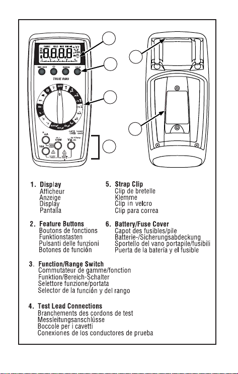
5
6
3
4
1
2
34XR-A
34XR-A
Page 5

34XR-A
Professional Digital Multimeter
Users Manual
• Mode d’emploi
• Bedienungshandbuch
• Manuale d’Uso
• Manual de uso
PN 2728939
July 2006
©Amprobe© Test Tools.
All rights reserved. Printed in Taiwan.
Page 6

Page 7

34XR-A Digital Multimeter
Contents
Safety Information ...........................................................................................2
Introduction .....................................................................................................3
Making Measurements.....................................................................................3
Verify Instrument Operation..........................................................................3
Range Selection............................................................................................3
Correcting an Overload (o) Indication .........................................................3
Measuring DC Voltage ........................................... See Figure -1- ...............3
Measuring AC Voltage (True rms)............... See Figures -2- & -3- ...............4
Preparing for Current Measurements............................................................4
Measuring DC Current ........................................... See Figure -4- ...............4
Measuring AC Current (True rms)............... See Figures -3- & -5- ...............4
Measuring Resistance ........................................... See Figure -6- ...............5
Measuring Continuity............................................. See Figure -7- ...............5
Checking Diodes .................................................... See Figure -8- ...............5
Measuring Capacitance ......................................... See Figure -9- ...............5
Measuring Temperature ...................................... See Figure -10- ...............5
Measuring Frequency .......................................... See Figure -11- ...............6
Measuring Dutycycle .......................................... See Figure -12-...............6
Additional Features ..........................................................................................6
Input Test Lead Warning...............................................................................6
True-rms Measurements ..............................................................................6
MIN MAX Measurements..............................................................................6
Auto Power Off .............................................................................................7
HOLD Measurements....................................................................................7
Backlight.......................................................................................................7
Product Maintenance.......................................................................................7
Battery and Fuse Replacement............................. See Figure -13- ...............7
Repair ..............................................................................................................8
WARRANTY..................................................................................................9
Specifications ..................................................................................................9
Users Manual
1
Page 8

2
Safety Information
• The 34XR-A Digital Multimeter is UL, cUL, and EN61010-1 certified for
Installation Category III – 600V and Category II – 1000V. It is recommended for
use with local level power distribution, appliances, portable equipment, etc,
where only smaller transient overvoltages may occur, and not for primary
supply lines, overhead lines and cable systems.
• Do not exceed the maximum overload limits per function (see specifications)
nor the limits marked on the instrument itself. Never apply more than 1000V
dc/750 V ac rms between the test lead and earth ground.
• Inspect the DMM, test leads and accessories before every use. Do not use any
damaged part.
• Never ground yourself when taking measurements. Do not touch exposed
circuit elements or test probe tips.
• Do not operate the instrument in an explosive atmosphere.
• Exercise extreme caution when: measuring voltage >20V // current >10mA // AC
power line with inductive loads // AC power line during electrical storms //
current, when the fuse blows in a circuit with open circuit voltage >1000 V //
servicing CRT equipment.
• Always measure current in series with the load – NEVER ACROSS a voltage
source. Check fuse first. Never replace a fuse with one of a different rating.
• Remove test leads before opening the Battery Cover or case.
Symbols Used in this Manual
B Battery W Refer to the manual
T Double insulated X Dangerous Voltage
F Direct Current J Earth Ground
B Alternating Current R Audible tone
P Complies with EU directives
I Fuse
>
Underwriters
Laboratories, Inc
Page 9

3
Introduction
The 34XR-A is a True rms autoranging handheld digital multimeter for measuring
or testing the following:
• DC and AC voltage • Temperature
• DC and AC current • Capacitance
• Resistance • Diodes
• Frequency • Continuity
• Dutycycle
Additional features include: MIN MAX, HOLD, Backlight, and Range Lock
Making Measurements
Verify Instrument Operation
Before attempting to make a measurement, verify that the instrument is operational
and the battery is good. If the instrument is not operational, have it repaired before
attempting to make a measurement.
Range Selection
In addition to autoranging the 34XR-A allows you to manually select and lock a
range by pressing the RANGE button. RANGE appears on the display to indicate
that manual ranging is active. Each subsequent press of the range button steps the
meter to the next higher range. When the highest range is reached the next press
returns the meter to the lowest range. To return to autoranging press and hold the
RANGE button for 2 seconds. RANGE no longer shows on the display.
Use autorange for all initial measurements. Then, when appropriate, use the RANGE
button to select and lock a range.
Warning
To avoid electrical shock while manual ranging use the display
annunciators to identify the actual range selected.
Correcting an Overload (oor -o ) Indication W
An o indication may appear on the display to indicate that an overload condition
exists. For voltage and current measurements, an overload should be immediately
corrected by selecting a higher range. If the highest range setting does not
eliminate the overload, interrupt the measurement until the problem is identified
and eliminated. The o indication is normal for some functions; for example,
resistance, continuity, and diode test.
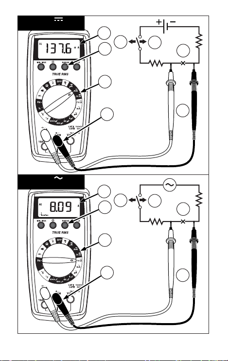
Measuring DC Voltage See Figure -1-
1. Set the Function Switch to v.
2. If RANGE is displayed, press the RANGE button to enable autoranging.
3. Connect the Test Leads: Red to E, Black to COM
4. Connect the Test Probes to the circuit test points.
5. Read the display, and, if necessary, correct any overload (o) conditions.
Page 10

4
Measuring AC Voltage (True rms) See Figures -2- & -3-
See Additional Features to find out the advantages of true rms.
1. Set the Function Switch to
V.
2. If RANGE is displayed, press the RANGE button to enable autoranging.
3. Connect the Test Leads: Red to E, Black to COM
4. Connect the Test Probes to the circuit test points
5. Read the display, and, if necessary, correct any overload (o) conditions.
Preparing for Current Measurements
• Turn off circuit power before connecting the test probes.
• Allow the meter to cool between measurements if current measurements
approach or exceeds 10 amps.
• A warning tone sounds if you connect a test lead to a current input before you
select a current range.
• Open circuit voltage at the measurement point must not exceed 1000 V.
• Always measure current in series with the load. Never measure current across a
voltage source.
Measuring DC Current See Figure -4-
1. Set the Function Switch to a A function and range.
2. If RANGE is displayed, press the RANGE button to enable autoranging.
3. Connect the Test Leads: Red to µA mA or 10A, Black to COM
4. Turn off power to the circuit being measured.
5. Open the test circuit (X) to establish measurement points.
6. Connect the Test Probes in series with the load.
7. Turn on power to the circuit being measured.
8. Read the display, and, if necessary, correct any overload (o) conditions.
Measuring AC Current (True rms) See Figures -3- & -5-
See Additional Features to find out the advantages of true rms.
1. Set the Function Switch to a a function and range.
2. If RANGE is displayed, press the RANGE button to enable autoranging.
3. Connect the Test Leads: Red to µA mA or 10A, Black to COM
4. Turn off power to the circuit being measured.
5. Open the test circuit (X) to establish measurement points.
6. Connect the Test Probes in series with the load.
7. Turn on power to the circuit being measured.
8. Read the display, and, if necessary, correct any overload (o) conditions.
Page 11

5
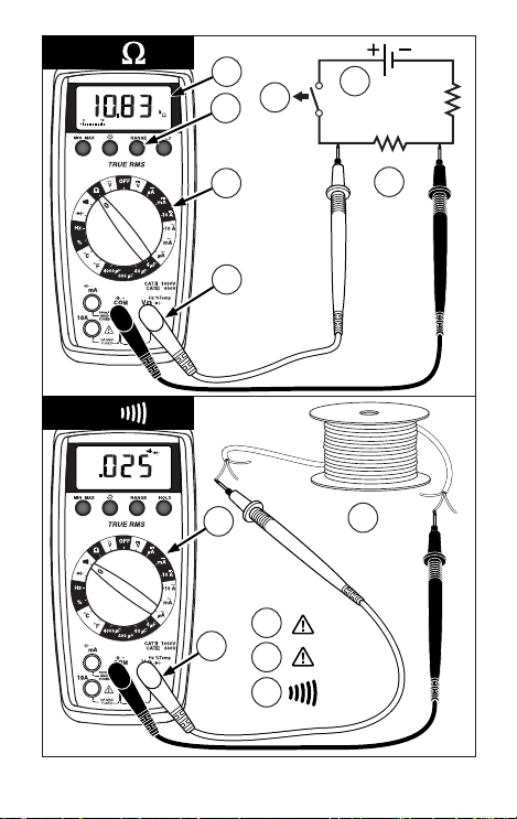
Measuring Resistance See Figure -6-
1. Set the Function Switch to Ω.
2. If RANGE is displayed, press the RANGE button to enable autoranging.
3. Connect the Test Leads: Red to E, Black to COM
4. Turn off power to the circuit being measured. Never measure resistance across
a voltage source or on a powered circuit.
5. Discharge any capacitors that may influence the reading.
6. Connect the Test Probes across the resistance.
7. Read the display. If o appears on the highest range, the resistance is too large
to be measured.
Measuring Continuity See Figure -7-
1. Set the Function Switch to R.
2. Connect the Test Leads: Red to E, Black to COM
3. Turn off power to the circuit being measured.
4. Discharge any capacitors that may influence the reading.
5. Connect the Test Probes across the resistance.
6. Listen for the tone that indicates continuity (< 35 Ω).
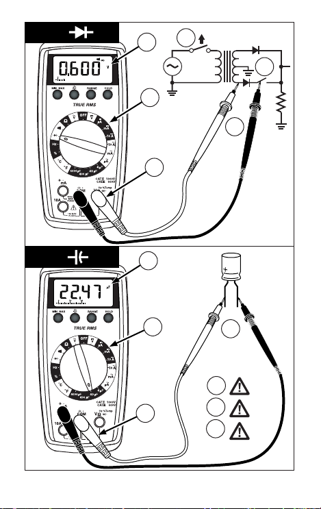
Checking Diodes See Figure -8-
1. Set the Function Switch to G.
2. Connect the Test Leads: Red to E, Black to COM
3. Turn off power to the circuit being measured.
4. Free at least one end of the diode from the circuit.
5. Connect the Test Probes across the diode.
6. Read the display. A good diode has a forward voltage drop of about 0.6 V. An
open or reverse biased diode will read o.
Measuring Capacitance See Figure -9-
1. Set the Function Switch to an appropriate µF function and range.
2. Connect the Test Leads: Red to COM, Black to µA mA P(-)
3. Turn off power to the circuit being measured.
4. Discharge the capacitor using a 100 kΩ resistor.
5. Free at least one end of the capacitor from the circuit.
6. Connect the Test Probes across the capacitor. When measuring an electrolytic
capacitor match the test lead polarity to the polarity of the capacitor.
7. Read the display.
Measuring Temperature See Figure -10-
1. Set the Function Switch to °C or °F.
2. Connect the K-type thermocouple to a TEMP adapter (XR-TA).
Match the polarity of the adapter to the polarity of the thermocouple.
3. Connect the TEMP adapter to the E and COM inputs.
Note: The 34XR-A is compatible with all K-type thermocouples. The K-type bead
thermocouple supplied with the meter is not intended for contact with liquids or electrical
circuits.
4. Expose the thermocouple to the temperature to be measured.
5. Read the display.
Page 12

6
Measuring Frequency See Figure -11-
1. Set the Function Switch to Hz.
2. Connect the Test Leads: Red to Hz, Black to COM
3. Connect the Test Probes to the signal source.
4. Read the display. The Meter will autorange for the best resolution.
Measuring Dutycycle See Figure -12-
1. Set the Function Switch to %.
2. Connect the Test Leads: Red to %, Black to COM
3. Connect the Test Probes to the signal source.
4. Read the display. The Meter will autorange for the best resolution.
Additional Features
Input Test Lead Warning
The meter emits a continuous tone when a test lead is placed in the µA mA or 10A
input jack and the Function/Range Switch is not set to a correct current position. (If
the meter is connected to a voltage source with leads connected for current, very
high current could result). All current ranges are protected by fast acting fuses.
True-rms Measurements
For ac measurements most DMMs average the ac input signal and display the
result as an estimated rms value. This average-responding method is accurate for
sinusoidal waveforms, but can be very inaccurate for distorted waveforms. To
ensure the most accurate measurements, always use a true-rms DMM when
measuring ac voltage or ac current on circuits for the following kinds of
applications:
• Power Supplies - diodes
• Controllers
• Power Limiting - SCR or Triac
• Starting - motors
• Florescent Lighting - ballasts
• Speed Control - motors
• Pulsed Signals
• Any non-sinusoidal ac waveform
MIN MAX Measurements
The MIN MAX function reads and updates the display to show the maximum or
minimum value measured after you press the MIN MAX button.
Pressing the MIN MAX button for less than 1 second will put the meter into a mode
of displaying the maximum, minimum, or actual readings. Each time the button is
pressed, the meter will cycle to the next display mode as shown in the table below.
Press the MIN MAX button for more than 2 seconds to exit MIN MAX.
Button Display Value Displayed
< 1 second
MAX
Maximum value after feature activated
< 1 second
MIN
Minimum value after feature activated
< 1 second
MIN MAX (blinks)
Normal measurement, actual reading
> 2 seconds
Exit MIN MAX
Normal measurement, actual reading
Page 13

7
Auto Power Off
Auto Power Off is a battery saving feature that puts the meter into a sleep mode if
the Function/Range Switch has not changed position in the last 30 minutes. To
wake the meter turn it off and then on.
The Auto Power Off feature can be disabled to keep the meter from going to sleep.
This feature is useful when using the MIN MAX mode for extended periods. To
disable the Auto Power Off feature use the following procedure:
1. Set the Function Switch to OFF.
2. Press and hold the MIN MAX button while turning the Function Switch to the
desired function.
3. Continue to press the MIN MAX button until the display finishes this
initialization period and the reading settles.
4. Release the MIN MAX button. The Auto Power Off feature will remain disabled
until the meter is turned off and then on.
HOLD Measurements
The HOLD button causes the meter to capture and continuously display a
measurement reading. To use the HOLD feature make a measurement, and then,
after the reading has stabilized, momentarily press the HOLD button. You can
remove the test leads and the reading will remain on the display. Pressing the
HOLD button again releases the display.
Backlight
Pressing the L button illuminates the display with a blue backlight. The backlight
will automatically turn off in about 60 seconds. Frequent use of the backlight will
decrease battery life.
Product Maintenance
Cleaning
To clean the meter, use a soft cloth moistened with water. To avoid damage to the
plastic components do not use benzene, alcohol, acetone, ether, paint thinner,
lacquer thinner, ketone or other solvents to clean the meter.
Troubleshooting
If the meter appears to operate improperly, check the following items first.
1. Review the operating instructions to ensure the meter is being used properly.
2. Inspect and test the continuity of the test leads.
3. Make sure the battery is in good condition. The low battery symbol B appears
when the battery falls below the level where accuracy is guaranteed. Replace a
low-battery immediately.
4. Check the condition of the fuses if the current ranges operate incorrectly.
Battery and Fuse Replacement See Figure -13-
XWWARNING
To avoid electrical shock remove the test leads from both the
meter and the test circuit before accessing the battery or the
fuses.
Page 14

8
To access the battery and the mA fuse remove the two screws holding the
Battery/Fuse Cover in place, and lift the cover from the meter.
To replace the mA fuse, pry it from its clips using a small screwdriver. A spare mA
fuse is located between the battery and the mA fuse.
mA Fuse: Fast Blow 315mA/1000V, minimum interrupt rating 30 kA
(6.3 x 32 mm) (Amprobe FP300)
To replace the 10 A fuse: 1) Remove the battery. 2) Remove the four rear-case
screws. 3) Separate the case. 4) Remove the 10 A fuse cover. 5) Remove and
replace the 10A fuse. 6) Re-install the fuse cover. 7) Reassemble the meter.
10A Fuse: Fast Blow 10A/1000V, minimum interrupt rating 30 kA
(10 x 38 mm) (Amprobe FP100).
Repair
All test tools returned for warranty or non-warranty repair or for calibration should be
accompanied by the following: your name, company’s name, address, telephone number,
and proof of purchase. Additionally, please include a brief description of the problem or the
service requested and include the test leads with the meter. Non-warranty repair or
replacement charges should be remitted in the form of a check, a money order, credit card
with expiration date, or a purchase order made payable to Amprobe
Test Tools.
In-Warranty Repairs and Replacement – All Countries
Please read the warranty statement and check your battery before requesting repair. During
the warranty period any defective test tool can be returned to your Amprobe
Test Tools
distributor for an exchange for the same or like product. Please check the “Where to Buy”
section on www.amprobe.com
for a list of distributors near you. Additionally, in the United
States and Canada In-Warranty repair and replacement units can also be sent to a
Amprobe
Test Tools Service Center (see below for address).
Non-Warranty Repairs and Replacement – US and Canada
Non-warranty repairs in the United States and Canada should be sent to a Amprobe Test
Tools Service Center. Call Amprobe
Test Tools or inquire at your point of purchase for
current repair and replacement rates.
In USA In Canada
Amprobe
Test Tools Amprobe Test Tools
Everett, WA 98203 Mississauga, ON L4Z 1X9
Tel: 888-993-5853 Tel: 905-890-7600
Fax: 425-446-6390 Fax: 905-890-6866
Non-Warranty Repairs and Replacement – Europe
European non-warranty units can be replaced by your Amprobe Test Tools distributor for
a nominal charge. Please check the “Where to Buy” section on www.amprobe.com
for a list
of distributors near you.
European Correspondence Address*
Amprobe
Test Tools Europe
P.O. Box 1186
5602 BD Eindhoven
The Netherlands
*(Correspondence only – no repair or replacement available from this address.
European customers please contact your distributor)
.
Page 15

9
WARRANTY
This 34XR-A Digital Multimeter is warranted against any defects of material or
workmanship within a period of three (3) years following the date of purchase of
the multimeter by the original purchaser or original user. Any multimeter claimed
to be defective during the warranty period should be returned with proof of
purchase to an authorized Amprobe Test Tools Service Center or to the local
Amprobe Test Tools dealer or distributor where your multimeter was purchased.
See Repair section for details. Any implied warranties arising out of the sale of a
Amprobe Test Tools multimeter, including but not limited to implied warranties of
merchantability and fitness for a particular purpose, are limited in duration to the
above stated three (3) year period. Amprobe Test Tools shall not be liable for loss
of use of the multimeter or other incidental or consequential damages, expenses, or
economical loss or for any claim or claims for such damage, expenses or
economical loss. Some states do not allow limitations on how long implied
warranties last or the exclusion or limitation of incidental or consequential
damages, so the above limitations or exclusions may not apply to you. This
warranty gives you specific legal rights, and you may also have other rights which
vary from state to state.
Specifications
General Specifications
Display: 3 ¾ digit liquid crystal display
(LCD)(3999 count) with a 41-segment
analog bar-graph.
Polarity: Automatic, positive implied,
negative polarity indication. Overrange: (0o)
or (-0o) is displayed.
Zero: Automatic.
Low battery indication: The B is
displayed when the battery voltage drops
below the operating level.
Aut
o power off: Approx. 30 minutes.
Measurement rate: 2 times per second,
nominal.
Operating environment: 0 °C to 50 °C at
<70 % R.H.
Storage temperature: -20 °C to 60 °C, 0
to 80 % R.H. with battery removed from
meter.
Temperature Coefficient: 0.1 ×
(specified accuracy) per °C. (0 °C to 18 °C,
28 °C to 50 °C).
Altitude: 2000 m (6562 feet)
Power: Single standard 9-volt battery,
NEDA 1604, JIS 006P, IEC 6F22.
Battery life: 100 hours typical with
carbon-zinc. 200 hours typical with alkaline.
Frequent use of the backlight will decrease
battery life.
Dimensions: 196 mm (H) × 92 mm (W) ×
60 mm (D).
Weight: Approximately 400 g including
battery.
Box contents:
The 34XR-A includes the following items:
Test leads w/ alligator clips
1 set
Holster
1
Magnet Strap
1
Temperature Adapter
1
K-type thermocouple
1
Users Manual
1
9 V battery (installed)
1
mA fuse, 0.315 A/ 1000 V
1 spare
Page 16

10
Approvals:
>
LISTED
950Z
P
Safety: Conforms to UL1244; EN61010-1:
Cat II - 1000V / Cat III - 600V; Class 2,
Pollution degree II.
EMC:
Conforms to EN61326-1, criteria B
This product complies with requirements of
the following European Community
Directives: 89/ 336/ EEC (Electromagnetic
Compatibility) and 73/ 23/ EEC (Low
Voltage) as amended by 93/ 68/ EEC (CE
Marking). However, electrical noise or
intense electromagnetic fields in the vicinity
of the equipment may disturb the
measurement circuit. Measuring
instruments will also respond to unwanted
signals that may be present within the
measurement circuit. Users should exercise
care and take appropriate precautions to
avoid misleading results when making
measurements in the presence of electronic
interference.
Electrical Specifications
(Accuracy at 23 °C ±5 °C, <75 % relative
humidity)
DC VOLTS
Ranges: 400mV, 4V, 40V, 400V, 1000V
Resolution: 100 µV in 400mV range
Accuracy: ±(0.5 % rdg + 1 dgt)
Input impedance:
400mV: >100 M
Ω; 4V: 10 MΩ; 40V to
1000V: 9.1 M
Ω
Overload protection: 1000 V dc /
750 Vac rms
AC VOLTS true rms (45Hz - 2kHz)
Ranges: 400m, 4V, 40V, 400V, 750V
Resolution: 100 µV
Accuracy:
±(1.2 % rdg +8 dgts) 45 Hz to 100 Hz on
400mV range
±(1.2 % rdg + 8 dgts) 45 Hz to 500 Hz
±(2.0 % rdg +8 dgts) 500 Hz to 2 kHz
±(2.0 % rdg + 8 dgts) 45 Hz to 1 kHz on
750 V range
Crest Factor: ≤ 3
Input impedance: 400mV: >100 MΩ;
4V: 10 M
Ω; 40V to 1000V: 9.1 MΩ
AC coupled true rms specified from
5 % to 100 % of range
Overload protection: 1000 V dc or
750 V ac rms
DC CURRENT
Ranges: 400µA, 4000µA, 40mA, 300mA,
10A
Resolution: 0.1µA
Accuracy: ±(1.0 % rdg + 1 dgt) on 400µA to
300mA ranges
±(2.0 % rdg + 3 dgts) on 10A range
Burden voltage:
400 µA Range: 1 mV/ 1 µA
4 mA Range: 500 mV/ 1 mA
40 mA Range: 10 mV/ 1 mA
300 mA: 8 mV/ 1 mA
10A: 40 mV/ 1 A
Input protection: 0.315A/1000V fast blow
ceramic fuse 6.3×32mm on µA/mA input
10A/1000V fast blow ceramic fuse
10×38mm on 10A input
10A input: 10 A for 5 minutes maximum
followed by a 10 minute cooling period
AC CURRENT true rms (45Hz - 1kHz)
Ranges: 400µA, 4000µA, 40mA, 300mA,
10A
Resolution: 0.1 µA
Accuracy: ±(1.5 % rdg + 8 dgts) on 400µA
to 300mA ranges
±(2.5 % rdg + 10 dgts) on 10A range
Crest Factor: ≤ 3
Burden Voltage: See DC Current
Input protection: 0.315A/1000V fast blow
ceramic fuse 6.3×32mm on µA/mA input
10A/1000V fast blow ceramic fuse
10×38mm on 10A input
10A input: 10 A for 4 minutes maximum
followed by a 12 minute cooling period
Page 17

11
RESISTANCE
Ranges: 400Ω, 4kΩ, 40kΩ, 400kΩ, 4MΩ,
40M
Ω
Resolution: 100 m
Ω
Accuracy: ±(1.0 % rdg + 4 dgts) on
400Ω to 4MΩ ranges
±(2.0 % rdg + 5 dgts) on 40M
Ω range
Open circuit volts: -0.45 V dc typical,
(-1.2 V dc on 400
Ω range)
Overload protection: 1000 V dc or
750 V ac rms
CAPACITANCE
Ranges: 4µF, 40µF, 400µF, 4000µF
Resolution: 1 nF
Accuracy:
±(5.0 % rdg + 10 dgts) on 4µF range
±(5.0 % rdg + 5 dgts) on 40µF to
400µF ranges
±(5.0 % rdg + 15 dgts) on 4000µF range
Test voltange: < 3.0 V
Test Frequency: 25Hz
Input protection: 0.315A/1000V fast blow
ceramic fuse 6.3×32mm on µA/mA input
TEMPERATURE
Ranges: -20 °C to 1000 °C, -4 °F to 1832 °F
Resolution: 1 °C, 1 °F
Accuracy:
±(2.0 % rdg + 4 °C) -20 °C to 10 °C
±(1.0 % rdg + 3 °C) 10 °C to 200 °C
±(3.0 % rdg + 2 °C) 200 °C to 1000 °C
±(2.0 % rdg + 8 °F) -4 °F to 50 °F
±(1.0 % rdg + 6 °F) 50 °F to 400 °F
±(3.0 % rdg + 4 °F) 400 °F to 1832 °F
Overload protection: 1000 V dc or
750 V ac rms
FREQUENCY
Ranges: 4k, 40k, 400k, 4M, 40MHz
Resolution: 1 Hz
Accuracy: ±(0.1 % rdg + 3 dgts)
Sensitivity:
10 Hz to 4 MHz: >1.5 V ac rms;
4 MHz to 40 MHz: >2 V ac rms, <5 V ac rms
Minimum pulse width: > 25 ns
Duty cycle limits: > 30 % and < 70 %
Overload protection: 1000 V dc or
750 V ac rms
DUTY CYCLE
Ranges: 0 to 90 %
Resolution: 0.1 %
Pulse widh: >10 µs
Frequency range: 40 Hz to 20 kHz
Accuracy: (5V logic ) ±(2.0% rdg + 5 dgts)
Overload protection: 1000 V dc or
750 V ac rms
CONTINUITY
Audible indication: < 35 Ω
Response time: 100 ms
Overload protection:1000 V dc or
750 V ac rms
DIODE TEST
Test current: approximately 1.2 mA
Accuracy: ±(1.5 % rdg + 3 dgts)
Resolution: 1 mV
Open circuit volts: 3.0 V dc typical
Overload protection: 1000 V dc or
750 V ac rms
ADDITIONAL FEATURES
µA mA, 10A Test Lead Connection: Beeps
to warn test leads are connected to
measure current while Function/Range
Switch is not set to a measure current.
MIN MAX: Displays the minimum or
maximum value detected while making a
measurement.
HOLD: Holds the latest reading on the
display.
RANGE: Manual range mode.
Backlight: Backlight auto-off
approximately 60 seconds
Auto Power off: 30 minutes, typical
REPLACEMENT PARTS
TL36 Test Lead Set with Alligator clips
FP300 mA fuse - Fuse Pack .315A/1000V
(4 each)
FP100 10A fuse - Fuse Pack 10A/1000V
(2 each)
XR-TA Input Adapter for K-type
thermocouple
TP255 K type thermocouple
XR-H2 Magne-Grip
®
Holster, clip, magnet,
and strap
Page 18

12
( )
( )
4
3
2
1
5
( )
( )
%
4
3
2
1
5
1
2
V
V
34XR-A
34XR-A
Page 19
13
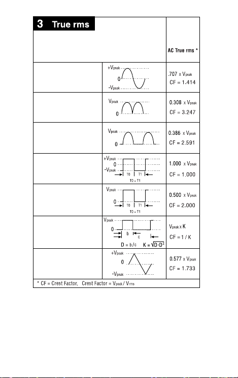
Input Waveform
Signal d'entrée
Eingangsschwingungsform
Forma d'onda d'ingresso
Forma de onda de entrada
Sine Wave
Sinusoïdale
Sinusschwingung
Onda sinusoidale
Onda sinusoidal
Full Wave, Sine Wave
Onde complète, Sinusoïdale
Volle Schwingung, Sinusschwingung
Onda sinusoidale, onda intera
Onda completa, Onda sinusoidal
Half-Wave, Sine Wave
Demi-onde, sinusoïdale
Halbschwingung, Sinusschwingung
Onda sinusoidale, semionda
Media onda, onda sinusoidal
Square Wave
Onde carrée
Rechteckschwingung
Onda quadra
Onda cuadrada
Square Wave
Onde carrée
Rechteckschwingung
Onda quadra
Onda cuadrada
Pulse Wave
Onde impulsionnelle
Impulsschwingung
Onda delI'impulso
Onda de impulsos
Sawtooth Wave
Onde en dent de scie
Sägezahnschwingung
Onda a denti di sega
Onda diente de sierra
34XR-A
Page 20
14
( )
( )
%
2
1
8
3
( )
( )
4
5
4
7
5
6
4
7
5
6
A
3
A
2
1
8
34XR-A
34XR-A
Page 21
15
( )
( )
( )
( )
3
4
6
5
2
1
5
3
4
6
6
7
2
1
7
34XR-A
34XR-A
Page 22
16
( )
( )
( )
( )
6
2
8
1
3
5
4
1
7
4
5
6
2
9
3
34XR-A
34XR-A
Page 23

17
( )
( )
4
11
1
3
2
2
4
K
( )
( )
3
1
5
10
34XR-A
34XR-A
Page 24

18
3
( )
( )
2
1
4
12
(2)
(4)
(2)
13
34XR-A
Page 25

Multimètre numérique 34XR-A
Table des matières
Consignes de sécurité........................................................................................2
Introduction .......................................................................................................3
Opérations de mesure........................................................................................3
Vérifier le fonctionnem ent de l’appareil....................................................................3
Sélection de gamme ..................................................................................................3
Correction d’une indication de surcharge (o)........................................................3
Mesures de tension c.c. ............................................... Voir Figure -1-.................... 3
Mesure de tension alt ernative (eff. vraie) ........Voir Figures -2- & -3- ....................4
Préparation des mesures de courant .......................................................................4
Mesures de courant c.c. ...............................................Voir Figur e -4-....................4
Mesure de courant alternatif (eff. vraie) ........... Voir Figure –3- & -5-....................4
Mesures de résistance .................................................Voir Figure -6- ....................5
Mesure de continuité ....................................................Voir Figu re -7-....................5
Contrôle de diodes ........................................................Voir Figure -8- ....................5
Mesure de capacité ......................................................Voir Figure -9- ....................5
Mesure de température .............................................Voir Figure -10-....................5
Mesure de fréquence .................................................Voir Figure -11- ....................6
Mesure du rapport cyclique .......................................Voir Figure -12- ....................6
Autres fonctions.................................................................................................6
Avertissement de cordon d’entrée............................................................................6
Mesures efficaces vraies ...........................................................................................6
Mesures MIN MAX ....................................................................................................6
Arrêt automatique ......................................................................................................7
Mesures en maintien HO LD......................................................................................7
Rétroéclairage ............................................................................................................7
Entretien du produit ...........................................................................................7
Nettoyage ...................................................................................................................7
Dépannage .................................................................................................................7
Remplacement des fusib les et des piles................... Voir Figure -13-....................7
Réparation .........................................................................................................8
GARANTIE ..................................................................................................................9
Caractéristiques .................................................................................................9
Mode d'emploi
1
Page 26

2
Consignes de sécurité
• Le multimètre numérique 34XR-A est certifié UL, cUL et EN61010-1 pour les
catégories d’installation III – 600 V et II – 1000 V. Il est recommandé pour les
appareils, les équipements portables et la distribution d’énergie au niveau local,
etc., où seules de petites surtensions transitoires sont possibles ; il n’est pas
destiné aux lignes du réseau d’alimentation électrique primaire, aux lignes
aériennes ou aux systèmes câblés.
• Ne pas dépasser les limites de surcharge maximum par fonction (voir les
caractéristiques techniques) ou les limites indiquées sur l’appareil lui-même.
Ne jamais appliquer plus de 1000 V c.c. / 750 V c.a. rms entre le cordon de test
et la prise de terre.
• Inspecter le multimètre numérique, les cordons de test et les accessoires avant
toute utilisation. Ne pas utiliser de pièce endommagée.
• Ne jamais se mettre à la terre en prenant des mesures. Ne toucher ni aux
éléments de circuit exposés ni aux pointes des sondes.
• Ne pas utiliser l’appareil dans une atmosphère explosive.
• Faire preuve d’extrême prudence en mesurant une tension > 20 V // un courant
> 10 mA // les lignes d’alimentation secteur avec charges inductives // les lignes
d’alimentation secteur pendant les orages électriques // un courant alors que le
fusible a sauté dans un circuit avec une tension en circuit ouvert > 1000 V //
lors d’une intervention sur un appareil à écran cathodique.
• Toujours mesurer le courant en série avec la charge – JAMAIS AUX BORNES
d’une source de tension. Vérifier d’abord le fusible. Ne jamais installer un
fusible de calibre différent.
• Retirer les cordons de test avant d’ouvrir le compartiment ou le boîtier
contenant la pile.
Symboles utilisés dans ce mode d’emploi
M Pile W Se reporter au
mode d’emploi
T Double isolation X Tension dangereuse
F Courant continu J Prise de terre
B Courant alternatif R Signal sonore
P Conforme aux directives
de l’UE
I Fusible
>
Underwriters
Laboratories, Inc.
Page 27

3
Introduction
Le 34XR-A est un multimètre numérique portable à gamme automatique permettant
de mesurer ou de tester les grandeurs efficaces vraies suivantes :
• Tension continue ou alternative • Température
• Courant continu ou alternatif • Capacité
• Résistance • Diodes
• Fréquence • Continuité
• Rapport cyclique
Autres fonctions incluses : MIN MAX, maintien d’affichage HOLD, rétroéclairage et
verrouillage de gamme.
Opérations de mesure
Vérifier le fonctionnement de l’appareil
Avant d’essayer de prendre une mesure, vérifiez que l’appareil est opérationnel et
que la pile est en bon état. Si l’appareil n’est pas opérationnel, faites-le réparer
avant de procéder à une mesure.
Sélection de gamme
En plus de la gamme automatique, le 34XR-A permet de sélectionner et de
verrouiller manuellement une gamme en appuyant sur le bouton RANGE. RANGE
s’affiche pour indiquer que la gamme manuelle est active. Chaque pression
successive du bouton de gamme (Range) fait passer le multimètre à la gamme
supérieure suivante. Arrivé à la gamme la plus élevée, la pression suivante du
bouton ramène le multimètre à la gamme la plus basse. Pour revenir en mode de
gamme automatique, maintenez le bouton RANGE enfoncé pendant 2 secondes. Le
mot RANGE disparaît de l’affichage. Utilisez la gamme automatique pour toutes vos
mesures initiales. Vous pouvez ensuite utiliser le bouton RANGE pour sélectionner
et verrouiller une gamme s’il y a lieu.
Avertissement
Pour éviter les chocs électriques en utilisant la gamme manuelle,
utiliser les indicateurs d’affichage pour identifier la gamme
sélectionnée.
Correction d’une indication de surcharge (o)
Une indication o apparaît parfois sur l’affichage pour indiquer la présence d’une
surcharge. Pour les mesures de courant et de tension, cette situation de surcharge
doit être immédiatement corrigée en sélectionnant une gamme plus élevée. Si le
choix de la gamme la plus élevée n’est pas suffisant, interrompez la mesure tant
que le problème n’a pas été identifié et éliminé. L’indication o est normale pour
certaines fonctions ; notamment pour la résistance, la continuité et le contrôle de
diodes.
Mesures de tension c.c. Voir Figure -1-
1. Réglez le commutateur de fonction sur v.
2. Si le mot RANGE apparaît, appuyez sur le bouton RANGE pour activer le mode
de gamme automatique.
3. Branchez les cordons de test : Rouge à E, noir à COM
4. Branchez les sondes de test aux points de test du circuit.
5. Lisez l’affichage et corrigez le cas échéant toute surch`arge (o).
Page 28

4
Mesure de tension alternative (eff. vraie) Voir Figures -2- & -3-
Reportez-vous à la section Autres fonctions pour découvrir les avantages des
mesures efficaces vraies.
1. Réglez le commutateur de fonction sur V.
2. Si le mot RANGE apparaît, appuyez sur le bouton RANGE pour activer le mode
de gamme automatique.
3. Branchez les cordons de test : rouge à E, noir à COM
4. Branchez les sondes de test aux points de test du circuit.
5. Lisez l’affichage et corrigez le cas échéant toute surcharge (o).
Préparation des mesures de courant
• Mettez le circuit hors tension avant de brancher les sondes de test.
• Laissez le multimètre refroidir entre les mesures si les mesures de courant
approchent ou dépassent 10 ampères.
• Un signal sonore retentit quand on branche un cordon de test dans une entrée
de courant avant d’avoir sélectionné une gamme de courant.
• La tension en circuit ouvert au point de mesure ne doit pas dépasser 1000 V.
• Toujours mesurer le courant en série avec la charge. Ne jamais mesurer le
courant aux bornes d’une source de tension.
Mesures de courant c.c. Voir Figure -4-
1. Réglez le commutateur de fonction sur une gamme ou une fonction A.
2. Si le mot RANGE apparaît, appuyez sur le bouton RANGE pour activer le mode
de gamme automatique.
3. Branchez les cordons de test : rouge à µA mA ou 10 A, noir à COM.
4. Mettez hors tension le circuit à mesurer.
5. Ouvrez le circuit de test (X) pour établir les points de mesure.
6. Branchez les sondes de test en série avec la charge.
7. Mettez sous tension le circuit à mesurer.
8. Lisez l’affichage et corrigez le cas échéant toute surcharge (o).
Mesure de courant alternatif (eff. vraie)Voir Figure –3- & -5-
Reportez-vous à la section Autres fonctions pour découvrir les avantages des
mesures efficaces vraies.
1. Réglez le commutateur de fonction sur une gamme ou une fonction a.
2. Si le mot RANGE apparaît, appuyez sur le bouton RANGE pour activer le mode
de gamme automatique.
3. Branchez les cordons de test : rouge à µA mA ou 10 A, noir à COM
4. Mettez hors tension le circuit à mesurer.
5. Ouvrez le circuit de test (X) pour établir les points de mesure.
6. Branchez les sondes de test en série avec la charge.
7. Mettez sous tension le circuit à mesurer.
8. Lisez l’affichage et corrigez le cas échéant toute surcharge (o).
Page 29

5
Mesures de résistance Voir Figure -6-
1. Réglez le commutateur de fonction sur Ω.
2. Si le mot RANGE apparaît, appuyez sur le bouton RANGE pour activer le mode
de gamme automatique.
3. Branchez les cordons de test : rouge à E, noir à COM
4. Mettez hors tension le circuit à mesurer. Ne mesurez jamais la résistance aux
bornes d’une source de tension sur un circuit alimenté.
5. Déchargez les condensateurs susceptibles d’influencer la lecture.
6. Branchez les sondes de test aux bornes de la résistance.
7. Lisez l’affichage. Si o apparaît sur la gamme la plus élevée, la résistance est
trop grande pour être mesurée.
Mesure de continuité Voir Figure -7-
1. Réglez le commutateur de fonction sur R.
2. Branchez les cordons de test : rouge à E, noir à COM
3. Mettez hors tension le circuit à mesurer.
4. Déchargez les condensateurs susceptibles d’influencer la lecture.
5. Branchez les sondes de test aux bornes de la résistance.
6. Notez la tonalité qui indique la continuité (< 35 Ω).
Contrôle de diodes Voir Figure -8-
1. Réglez le commutateur de fonction sur G.
2. Branchez les cordons de test : rouge à E, noir à COM
3. Mettez hors tension le circuit à mesurer.
4. Libérez du circuit au moins une extrémité de la diode.
5. Branchez les sondes de test aux bornes de la diode.
6. Lisez l’affichage. Une diode en bon état présente une chute de tension dans le
sens direct d’environ 0.6 V. Une diode ouverte ou polarisée dans le sens inverse
indique o.
Mesure de capacité Voir Figure -9-
1. Réglez le commutateur de fonction sur la gamme ou la fonction µF appropriée.
2. Branchez les cordons de test : rouge à COM, noir à µA mA P.(-)
3. Mettez hors tension le circuit à mesurer.
4. Déchargez le condensateur dans une résistance de 100 kΩ.
5. Libérez du circuit au moins une extrémité du condensateur.
6. Reliez les sondes de test aux bornes du condensateur. Pour mesurer un condensateur
électrolytique, alignez la polarité du cordon de test sur celle du condensateur.
7. Lisez l’affichage.
Mesure de température Voir Figure -10-
1. Réglez le commutateur de fonction sur °C ou °F.
2. Branchez le thermocouple de type K dans un adaptateur TEMP (XR-TA).
Alignez la polarité de l’adaptateur sur celle du thermocouple.
3. Branchez l’adaptateur TEMP aux entrées E et COM
Remarque : Le 34XR-A est compatible avec tous les thermocouples de type K. Le thermocouple de type K à boule fourni avec le multimètre n’est pas conçu pour entrer en contact
avec l’eau ou les circuits électriques.
4. Exposez la sonde du thermocouple à la température à mesurer.
5. Lisez l’affichage.
Page 30

6
Mesure de fréquence Voir Figure -11-
1. Réglez le commutateur de fonction sur Hz.
2. Branchez les cordons de test : rouge à Hz, noir à COM
3. Branchez les sondes de test à la source du signal.
4. Lisez l’affichage. Le multimètre détermine automatiquement la gamme pour
obtenir une résolution optimale.
Mesure du rapport cyclique Voir Figure -12-
1. Réglez le commutateur de fonction sur %.
2. Branchez les cordons de test : Rouge à %, noir à COM
3. Branchez les sondes de test à la source du signal.
4. Lisez l’affichage. Le multimètre détermine automatiquement la gamme pour
obtenir une résolution optimale.
Autres fonctions
Avertissement de cordon d’entrée
le multimètre émet une tonalité continue lorsqu’un cordon de test est placé dans le
jack d’entrée µA mA ou 10 A et que le commutateur de fonction/gamme n’est pas
réglé sur une position de courant qui convienne. (Une intensité très élevée risque
de se produire si le multimètre est connecté à une source de tension avec les
cordons placés pour une lecture de courant). Toutes les gammes de courant sont
protégées par des fusibles instantanés.
Mesures efficaces vraies
Pour les mesures en c.a., la plupart des multimètres numériques calculent la
moyenne du signal d’entrée c.a. et affichent le résultat sous la forme d’une valeur
efficace estimée. Cette méthode à valeur moyenne, précise pour les signaux
sinusoïdaux, peut être imprécise pour les signaux déformés. Pour obtenir les
mesures les plus précises, utilisez toujours un multimètre numérique de mesure
efficace vraie pour mesurer la tension alternative ou le courant alternatif sur les
circuits des applications suivantes :
• Alimentations - diodes
• Contrôleurs
• Limiteur de puissance - thyristor ou triac
• Démarrage - moteurs
• Eclairage fluorescent - ballasts
• Réglage de vitesse - moteurs
• Signaux d’impulsion
• Tous les signaux non-sinusoïdaux
Mesures MIN MAX
La fonction MIN MAX lit et met à jour l’affichage pour indiquer la valeur maximum
ou minimum mesurée lorsque le bouton MIN MAX est activé.
Si le bouton MIN MAX est enfoncé moins d’une seconde, le multimètre est mis
dans un mode d’affichage présentant les valeurs maximum, minimum ou brutes.
Chaque fois que ce bouton est activé, l’appareil passe alors au mode d’affichage
suivant, conformément au tableau ci-dessous. Appuyez sur le bouton MIN MAX
pendant plus de 2 secondes pour quitter MIN MAX.
Bouton Affichage Valeur affichée
< 1 seconde MAX Valeur maximum une fois la fonction activée
< 1 seconde MIN Valeur minimum une fois la fonction activée
< 1 seconde MIN MAX (clignote) Mesure normale, valeur réelle
> 2 secondes Quit ter MIN MAX
Mesure normale, valeur réelle
Page 31

7
Arrêt automatique
L’arrêt automatique est destiné à économiser la pile : le multimètre est placé en
mode de veille si la position du commutateur de fonction/gamme n’a pas été
modifiée depuis 30 minutes. Pour réactiver le multimètre, mettez-le hors tension,
puis sous tension.
Vous pouvez empêcher le multimètre de se mettre en veille en désactivant la
fonction d’arrêt automatique. Cette fonction est utile quand le mode MIN MAX doit
être utilisé pendant des périodes prolongées. Pour désactiver la fonction d’arrêt
automatique, effectuez l’opération suivante :
1. Réglez le commutateur de gamme sur OFF.
2. Maintenez le bouton MIN MAX enfoncé tout en réglant le commutateur de
fonction sur la fonction souhaitée.
3. Maintenez le bouton MIN MAX enfoncé jusqu’à la fin de la période
d’initialisation et jusqu’à ce que l’affichage se stabilise.
4. Relâchez le bouton MIN MAX. La fonction d’arrêt automatique reste désactivée
tant que le multimètre n’est pas mis hors tension, puis sous tension.
Mesures en maintien HOLD
Le bouton HOLD permet au multimètre de capturer et d’afficher en continu la valeur
mesurée. Pour utiliser la fonction HOLD, effectuez une mesure, puis une fois le
relevé stabilisé, appuyez momentanément sur le bouton HOLD. Vous pouvez
enlever les cordons de test ; la valeur reste affichée. Une nouvelle pression du
bouton HOLD libère l’affichage.
Rétroéclairage
La pression du bouton L illumine l’écran d’un rétroéclairage bleu. Le
rétroéclairage se met automatiquement en veille après 60 secondes environ. Une
utilisation trop fréquente du rétroéclairage fait réduit la durée de vie de la pile.
Entretien du produit
Nettoyage
Nettoyez le multimètre à l’aide d’un chiffon doux imbibé d’eau. Pour éviter
d’endommager les composants en plastique, n’utilisez pas de benzène, d’alcool,
d’éther, de diluant pour peinture, de diluant à peinture-laque, de cétone ou d’autres
solvants lors du nettoyage du multimètre.
Dépannage
Si le multimètre ne semble pas fonctionner normalement, vérifiez d’abord les
éléments suivants.
1. Relisez les consignes d’utilisation pour confirmer que le multimètre est
utilisé correctement.
2. Inspectez et testez la continuité des cordons de test.
3. Assurez-vous que la pile est en bon état. Le symbole de pile faible M apparaît
lorsque la tension de la pile tombe en dessous du niveau garantissant la
précision. Remplacez immédiatement une pile faible.
4. Vérifiez l’état des fusibles si les gammes de courant ne fonctionnent pas correctement.
Remplacement des fusibles et des piles Voir Figure -13-
XWAVERTISSEMENT
Pour éviter les chocs électriques, retirer les cordons de test du
multimètre et du circuit de test avant d’accéder à la pile ou
aux fusibles.
Page 32

8
Pour accéder à la pile et au fusible mA, retirez les deux vis maintenant le couvercle
de pile/fusible en place, et enlevez-le du multimètre.
Pour remplacer le fusible mA, séparez-le de ses attaches à l’aide d’un petit
tournevis. Un fusible mA de rechange se trouve entre la pile et le fusible mA.
Fusible mA : Fusible instantané 0.315 mA / 1000 V, (Amprobe
FP300) à
pouvoir de coupure minimum de 30 kA (6.3 x 32 mm)
Pour remplacer le fusible 10 A : 1) Retirez la pile. 2) Retirez les quatre vis du boîtier
arrière. 3) Séparez le boîtier. 4) Retirez le capot de fusible 10 A. 5) Retirez et
remplacez le fusible de 10 A. 6) Remettez le capot du fusible. 7) Réassemblez
le multimètre.
Fusible 10 A : Fusible instantané 10 A / 1000 V (Amprobe
FP100) à pouvoir
de coupure minimum de 30 kA (10 x 38 mm)
Réparation
Tous les outils de test renvoyés pour un étalonnage ou une réparation couverte ou
non par la garantie doivent être accompagnés des éléments suivants : nom, raison
sociale, adresse, numéro de téléphone et justificatif d'achat. Ajoutez également une
brève description du problème ou du service demandé et incluez les cordons de
test avec le multimètre. Les frais de remplacement ou de réparation hors garantie
doivent être acquittés par chèque, mandat, carte de crédit avec date d'expiration ou
par bon de commande payable à l'ordre de Amprobe Test Tools.
Remplacements et réparations sous garantie – Tous pays
Veuillez lire la déclaration de garantie, et vérifier la pile avant de demander une
réparation. Pendant la période de garantie, tout outil de test défectueux peut être
renvoyé auprès de votre distributeur Amprobe Test Tools pour être échangé
contre un produit identique ou similaire. Consultez la section « Where to Buy » sur
le site www.amprobe.com pour obtenir la liste des distributeurs dans votre région.
Au Canada et aux Etats-Unis, les appareils devant être remplacé ou réparé sous
garantie peuvent également être envoyés dans un centre de services Amprobe
Test Tools (voir les adresses ci-dessous).
Remplacements et réparations hors garantie – Canada et
Etats-Unis
Les appareils à réparer hors garantie au Canada et aux Etats-Unis doivent être
envoyés dans un centre de services Amprobe Test Tools. Appelez Amprobe Test
Tools ou renseignez-vous auprès de votre lieu d’achat pour connaître les tarifs en
vigueur pour le remplacement ou les réparations.
Aux Etats-Unis Au Canada
Amprobe Test Tools Amprobe Test Tools
Everett, WA 98203 Mississauga, Ontario L4Z 1X9
Tél. : 888-993-5853 Tél. : 905-890-7600
Fax : 425-446-6390 Fax : 905-890-6866
Remplacements et réparations hors garantie – Europe
Les appareils européens non couverts par la garantie peuvent être remplacés par
votre distributeur Amprobe
Test Tools pour une somme nominale. Consultez la
section « Where to Buy » sur le site www.amprobe.com pour obtenir la liste des
distributeurs dans votre région.
Adresse postale européenne*
Amprobe
Test Tools Europe
P.O. Box 1186
5602 B.D. Eindhoven
Pays-Bas
*(Réservée à la correspondance – Aucun remplacement ou réparation n’est
possible à cette adresse. Nos clients européens doivent contacter leur distributeur).
Page 33

9
GARANTIE
Le multimètre numérique 34XR-A est garanti contre tout défaut de fabrication ou de
main d’œuvre pendant une période d’trois (3) ans à compter de la date d’achat du
multimètre par l’acheteur initial ou l’utilisateur initial. Tout multimètre faisant l’objet
d’un défaut pendant la période de garantie doit être renvoyé accompagné d’un
justificatif d’achat au près d’un centre de services agréé par Amprobe Test ou du
distributeur ou du revendeur local de Amprobe
Test Tools où l’achat du multimètre a
été effectué. Voir la section Réparation pour tous les détails. Toutes les garanties
implicites résultant de la vente d’un multimètre Amprobe
Test Tools, y compris mais
sans s’y limiter les garanties de commercialisation ou d’adaptation à un usage
particulier, sont limitées à la durée d’trois (3) an déjà citée. Amprobe Test Tools ne
sera pas tenu responsable de la privation de jouissance du multimètre ou d’autres
dommages directs ou indirects, frais ou pertes économiques ni des poursuites
engagées pour de tels dommages, frais ou pertes économiques. Certains pays
n’admettent pas les limitations sur la durée des g aranties implicites, ni sur l’exclusion
ou la limitation des dommages directs ou indirects ; il est donc possible que les
limitations ou exclusions de cette garantie ne s’appliquent pas dans votre cas. La
présente garantie confère certains droits juridiques : la législation du pays ou de l’état
peut vous en accorder d’autres.
Caractéristiques
Caractéristiques générales
Affichage : Afficheur à cristaux liquides
(LCD) à 3 ¾ chiffres de résolution
(3999 comptes) avec un affichage
incrémental analogique à 41 segments.
Polarité : Indication de la polarité négative,
à implication positive, automatique.
Dépassement de gamme : (0o) ou (-0o)
apparaî.
Zéro : Automatique.
Témoin de pile faible : Le symbole M
est affiché lorsque la tension de pile chute
en dessous du niveau d’exploitation.
Arrêt automatique : Environ 30 minutes.
Vitesse de mesure : 2 fois par seconde,
nominal.
Environnement de fonctionnement :
0 °C à 50 °C à < 70 % H.R.
Température d’entreposage :
-20 °C à 60 °C, 0 à 80 % H.R. avec la pile
extraite du multimètre.
Coefficient thermique :
0.1 × (précision spécifiée) par °C. (0 °C à
18 °C, 28 °C à 50 °C).
Altitude : 2000 m (6562 pieds)
Alimentation
: Pile standard unique de
9 volts, NEDA 1604, JIS 006P, CEI 6F22.
Durée de vie de pile : 100 heures en
moyenne pour les piles au carbone-zinc.
200 heures en moye pour les piles alcalines.
Une utilisation trop fréquente du
rétroéclairage fait baisser réduit la durée de
vie de la pile
Dimensions : 196 mm (H) × 92 mm (l) ×
60 mm (P).
Poids : Environ 400 g pile incluse.
Contenu du coffret :
Le 34XR-A comprend les éléments
suivants :
Cordons de test avec pinces
crocodiles
1 jeu
Etui
1
Bretelle magnétique
1
Adaptateur de température
1
Thermocouple de type K
1
Mode d’emploi
1
Pile 9 V (installée)
1
Fusible mA, 0.315 A/ 1000 V 1 de
rechange
Page 34

10
Homologations :
>
LISTED
950Z
P
Sécurité : Conforme à EN61010- 1: Cat II –
1000 V / Cat III – 600 V ; Classe 2, degré de
pollution II ; UL1244.
CEM : Conforme à EN61326-1.
Ce produit est conforme aux exigences des
directives suivantes de la Communauté
européenne : 89/ 336/ CEE (Compatibilité
électromagnétique) et 73/ 23/ CEE (Basse
tension) modifiée par 93/ 68/ CEE
(Marquage CE). Toutefois, le bruit
électrique ou les champs
électromagnétiques intenses à proximité de
l’équipement sont susceptibles de perturber
le circuit de mesure. Les appareils de
mesure réagissent également aux signaux
indésirables parfois présents dans le circuit
de mesure. Les utilisateurs doivent faire
preuve de prudence et prendre les mesures
nécessaires pour éviter les erreurs de
mesure en présence de parasites
électromagnétiques.
Caractéristiques électriques
(Précision à 23 °C ± 5 °C, < 75 %
d’humidité relative)
VOLTS C.C.
Gammes : 400 mV, 4 V, 40 V, 400 V, 1000 V
Résolution : 100 µV en 400 mV de gamme
Précision : ±(0.5 % de lecture + 1 chiffre)
Impédance d’entrée :
400 mV : > 100 M
Ω ; 4 V : 10 MΩ ; 40 V à
1000 V : 9.1 M
Ω
Protection contre les surcharges : 1000 V
c.c. / 750 V c.a. eff.
VOLTS C.A. eff. vrai (45 Hz – 2 kHz)
Gammes : 400 mV, 4 V, 40 V, 400 V, 750 V
Résolution : 100 µV
Précision :
±(1.2 % de lecture + 8 chiffres) 45 Hz à
100 Hz sur la gamme 400 mV
±(1.2 % de lecture + 8 chiffres) 45 Hz à
500 Hz
±(2.0 % de lecture + 8 chiffres) 500 Hz à
2 kHz
±(2.0 % de lecture + 8 chiffres) 45 Hz à
1 kHz sur la gamme 750 V
Facteur de crête :
≤ 3
Impédance d’entrée : 400 mV : 100 M
Ω
4 V : 10 MΩ ; 40 V à 1000 V : 9.1 MΩ
Mesure eff. vraie couplée en c.a. spécifiée
entre 5 % et 100 % de la gamme
Protection contre les surcharges : 1000 V
c.c. ou 750 V c.a. eff.
COURANT C.C.
Gammes : 400 µA, 4000 µA, 40 mA,
300 mA, 10
Résolution : 0.1 µA
Précision : ±(1.0 % de lecture + 1 chiffre)
sur les gammes de 400 µA à 300 mA
±(2.0 % de lecture + 3 chiffres) sur la
gamme 10 A
Tension de charge :
400
µ Gamme A : 1 mV / 1 µA
Gamme 4 mA : 500 mV / 1 mA
Gamme 40 mA : 10 mV / 1 mA
300 mA : 8 mV / 1 mA
10 A : 40 mV / 1 A
Protection d’entrée : Fusible instantané
0.315 A / 1000 V céramique 6.3 × 32 mm
sur l’entrée µA/mA Fusible instantané
10 A / 1000 V céramique 10 × 38 mm sur
l’entrée 10 A
Entrée 10 A : 10 A pendant 4 minutes
maximum suivis d’une 12 minute période
de refroidissement
COURANT C.A. eff. vraie (45 Hz – 1 kHz)
Gammes : 400 µA, 4000 µA, 40 mA,
300 mA, 10 A
Résolution : 0.1 µA
Précision : ±(1.5 % de lecture + 8 chiffres)
sur les gammes de 400 µA à 300 mA
±(2.5 % de lecture + 10 chiffres) sur la
gamme 10 A
Facteur de crête :
≤ 3
Tension de charge : Voir Courant c.c.
Protection d’entrée : Fusible instantané
0.315 A / 1000 V céramique 6.3 × 32 mm
sur l’entrée µA / mA Fusible instantané
10 A / 1000 V céramique 10 × 38 mm sur
l’entrée 10 A
Entrée 10 A : 10 A pendant 4 minutes
maximum suivis d’une 12 minute période
de refroidissement
Page 35

11
RESISTANCE
Gammes : 400 Ω, 4 kΩ, 40 kΩ, 400 kΩ,
4 MΩ, 40 MΩ
Résolution : 100 m
Ω
Précision : ±(1.0 % de lecture + 4 chiffres)
sur les gammes de 400
Ω à 4 MΩ
±(2.0 % de lecture + 5 chiffres) sur la
gamme 40 MΩ
Volts en circuit ouvert : -0.45 V c.c. en
moyenne, (-1.2 V c.c. sur la gamme 400
Ω)
Protection contre les surcharges :
1000 V c.c. ou 750 V c.a. eff.
CAPACITE
Gammes : 4 µF, 40 µF, 400 µF, 4000 µF
Résolution : 0.1 nF
Précision :
±(5.0 % de lecture + 10 chiffres) sur la
gamme 4 uF
±(5.0 % de lecture + 5 chiffres) sur les
gammes 40 uF à 400 uF
±(5.0 % de lecture + 15 chiffres) sur la
gamme 4000 uF
Tension de test : < 3.0 V
Fréquence de test : 25 Hz
Protection d’entrée : Fusible instantané
céramique 0.315 A / 1000 V de
6.3 × 32 mm sur l’entrée µA / mA
TEMPERATURE
Plages :-20 °C à 1000 °C, -4 °F à 1832 °F
Résolution : 1 °C, 1 °F
Précision :
±(2.0 % de lecture + 4 °C) -20 °C à 10 °C
±(1.0 % de lecture + 3 °C) 10 °C à 200 °C
±(3.0 % de lecture + 2 °C) 200 °C à 1000 °C
±(2.0 % de lecture + 8 °F) -4 °F à 50 °F
±(1.0 % de lecture + 6 °F) 50 °F à 400 °F
±(3.0 % de lecture + 4 °F) 400 °F à 1832 °F
Protection contre les surcharges :
1000 V c.c. ou 750 V c.a. eff.
FREQUENCE
Gamme : 4 k, 40 k, 400 k, 4 M, 40 MHz
Résolution : 1 Hz
Précision : ±(0.1 % de lecture + 3 chiffres)
Sensibilité :
10 Hz à 4 MHz : > 1.5 V c.a. eff. ;
4 MHz à 40 MHz : > 2 V c.a. eff.,
< 5 V c.a. eff.
Largeur d’impulsion minimum : > 25 ns
Limites du rapport cyclique : > 30 %
et < 70 %
Protection contre les surcharges :
1000 V c.c. ou 750 V c.a. eff.
RAPPORT CYCLIQUE
Gamme : de 0 à 90 %
Résolution : 0.1 %
Largeur d’impulsion : > 10 µs
Précision : (5 V logique) ±(2.0 % de lecture
+ 5 chiffres)
Protection contre les surcharges :
1000 V c.c. ou 750 V c.a. eff.
CONTINUITE
Indication sonore : < 35 Ω
Temps de réponse : 100 ms
Protection contre les surcharges :
1000 V c.c. ou 750 V c.a. eff.
TEST DE DIODE
Courant de test : Environ 1.2 mA
Précision : ±(1.5 % de lecture + 3 chiffres)
Résolution : 1 mV
Volts en circuit ouvert : 3.0 V c.c. normal
Protection contre les surcharges :
1000 V c.c. ou 750 V c.a. eff.
AUTRES FONCTIONS
Branchement de cordon de test µA mA,
10 A : Emet un bip pour signaler que les
cordons de test sont branchés et prêts à
mesurer le courant, le commutateur de
fonction/gamme n’étant pas réglé sur une
mesure de courant.
MIN MAX : Affiche la valeur minimum ou
maximum détectée pendant la mesure.
HOLD : Maintient l’affichage de la dernière
valeur relevée.
GAMME : Mode de gamme manuelle.
Rétroéclairage : Le rétroéclairage s’éteint
automatiquement après 60 secondes
environ
Arrêt automatique : 30 minutes, normal
PIECES DE RECHANGE
TL36 Jeu de cordons de test avec
pinces crocodiles
FP300 Ensemble de fusibles mA –
0.315 A / 1000 V (4 par unité)
FP100 Ensemble de fusibles 10 A –
10 A / 1000 V (2 par unité)
XR-TA Adaptateur d’entrée pour
thermocouple de type K
TP255 Thermocouple de type K
XR-H2 Etui Magne-Grip
®
, pince, aimant
et bretelle
Page 36

12
Page 37

34XR-A Digital Multimeter
Inhalt
Inhalt..................................................................................................................1
Sicherheitsinformationen...................................................................................2
Einleitung...........................................................................................................3
Messungen durchführen....................................................................................3
Nachweisen der Funktionsfähigkeit des Instruments ...................................3
Bereichswahl................................................................................................3
Beheben einer Überlastanzeige (o).............................................................3
Messen von Gleichspannung ................... ..Siehe Abbildung -1-.................3
Messen von Wechselspannung
(True rms) .............................Siehe Abbildungen -2-und-3- .................4
Vorbereitung für Strommessungen..............................................................4
Messen von Gleichstrom ......................... ..Siehe Abbildung -4- .................4
Messen von Wechselstrom
(True rms) ...................................Siehe Abbildungen -3-und-5- .................4
Messen von Widerstand .......................... ..Siehe Abbildung -6- .................5
Messen von Kontinuität ........................... ..Siehe Abbildung -7- .................5
Prüfen von Dioden .....................................Siehe Abbildung -8- .................5
Messen von Kondensatorkapazität........... ..Siehe Abbildung -9- .................5
Messen von Temperatur .......................... Siehe Abbildung -10-.................5
Messen von Frequenz .............................. Siehe Abbildung -11-................. 6
Taktgrad messen ..................................... Siehe Abbildung -12- .................6
Zusätzliche Funktionen.......................................................................................6
Eingangsprüfleiter-Warnung ........................................................................6
Echt-Effektivwertmessung (true rms) ..........................................................6
MIN-MAX-Messungen .................................................................................6
Auto Power Off ............................................................................................7
HOLD-Messungen........................................................................................7
Hintergrundbeleuchtung ..............................................................................7
Produktwartung .................................................................................................7
Reinigung ....................................................................................................7
Fehlerbehebung ...........................................................................................7
Ersetzen der Batterie und Sicherung ........Siehe Abbildung -13- .................7
Reparatur...........................................................................................................8
GARANTIE....................................................................................................9
Technische Daten...............................................................................................9
Bedienungshandbuch
1
Page 38

2
Sicherheitsinformationen
• Das 34XR-A Digital Multimeter ist UL-, cUL- und EN61010-1-zertifiziert für
Installationsklasse III – 600 V und Klasse II – 1000 V. Anwendung ist empfohlen für
lokale Stromverteilung, Haushaltsgeräte, tragbare Geräte usw., bei denen nur
kleinere Spannungsspitzen auftreten können; Anwendung für primäre
Stromverteilung, Hochspannungsleitungen und Kabelsysteme wird nicht empfohlen.
• Die maximalen Überlastungsgrenzen der einzelnen Funktionen (siehe
Technische Daten) und die auf dem Instrument markierten Grenzwerte nicht
überschreiten. Zwischen Messleitung und Masse niemals mehr als 1000 VDC
/ 750 VAC rms anlegen.
• Vor jedem Gebrauch des DMM die Messleitungen und das Zubehör prüfen.
Keine beschädigten Teile verwenden.
• Sich selbst isolieren, wenn Messungen durchgeführt werden. Keine
freiliegenden Schaltungselemente oder Prüfspitzen berühren.
• Das Messgerät nicht in Umgebungen mit explosiven Gasen betreiben.
• In den folgenden Situationen besondere Vorsicht walten lassen: Messung von
Spannung > 20 V // Stromstärke >10 mA // Wechselspannungsleitungen mit
Induktivlasten // Wechselspannungsleitungen während Gewittern // Strom mit
einer durchgebrannten Sicherung in einem Schaltkreis mit Leerlaufspannung
>1000 V // bei der Wartung von Kathodenröhrengeräten.
• Strommessung immer in Serie mit der Last - NIEMALS über eine
Spannungsquelle. Zuerst die Sicherung prüfen. Niemals eine Sicherung durch
eine Sicherung anderer Nennlast ersetzen.
• Vor dem Öffnen des Batteriefachs bzw. des Gehäuses die Prüfleiter entfernen.
Symbole in diesem Handbuch
M Batterie W Im Handbuch
nachlesen.
T Schutzisoliert X Gefährliche
Spannung
F Gleichstrom J Erde, Masse
B W echselstrom R Akustischer Alarm
P Übereinstimmung mit
EU-Richtlinien
I Sicherung
>
Underwriters
Laboratories, Inc.
Page 39

3
Einleitung
Das Modell 34XR-A ist ein handgehaltenes Multimeter mit EffektivwertWechselspannung (True rms) und automatischer Bereichswahl, das folgende
Mess- und Testfunktionen bietet:
• Gleich- und Wechselspannung • Temperatur
• Gleich- und Wechselstrom • Kondensatorkapazität
• Widerstand • Dioden
• Frequenz • Kontinuität
• Tastgrad
Zusätzliche Leistungsmerkmale: MIN MAX, HOLD (Halten), Hintergrundbeleuchtung
und fixierter Bereich.
Messungen durchführen
Nachweisen der Funktionsfähigkeit des Instruments
Bevor Messungen durchgeführt werden, sicherstellen, dass das Instrument funktionsfähig
ist und die Batterie in gutem Zustand ist. Wenn das Instrument nicht funktionsfähig ist,
muss es repariert werden, bevor versucht wird, eine Messung durchzuführen.
Bereichswahl
Zusätzlich zur automatischen Bereichswahl können mit dem 34XR-A Bereiche
manuell ausgewählt und fixiert werden, indem die Taste RANGE gedrückt wird.
Wenn die manuelle Bereichswahl aktiviert ist, erscheint RANGE in der Anzeige.
Jedes weitere Drücken der Bereichswahltaste wählt den nächsthöheren Bereich des
Messgeräts. Nach dem höchsten Bereich wechselt das Messgerät wieder in den
niedrigsten Bereich. Um zur automatischen Bereichswahl zurückzukehren, wird die
Taste RANGE 2 Sekunden lang gedrückt gehalten. RANGE wird aus der Anzeige
ausgeblendet.
Bei allen Messungen sollte anfänglich die automatische Bereichswahl verwendet
werden. Anschließend nach Bedarf die Taste RANGE drücken, um einen Bereich
auszuwählen und zu fixieren.
Warnung
Um Stromschlag bei der Verwendung der automatischen Bereichswahl
zu vermeiden, den tatsächlich ausgewählten Bereich anhand der
Anzeiger identifizieren.
Beheben einer Überlastanzeige (o)
Wenn eine Überlastbedingung vorliegt, erscheint unter Umständen o in der
Anzeige. Bei Spannungs- und Strommessungen sollten Überlastbedingungen sofort
durch Wählen eines höheren Bereichs behoben werden. Wenn die höchste
Bereichseinstellung die Überlast nicht behebt, die Messung unterbrechen, bis das
Problem identifiziert und behoben wurde. Die Anzeige o ist für einige Funktionen
normal, z.B. für Widerstand, Kontinuität und Diodenprüfung.
Messen von Gleichspannung Siehe Abbildung -1-
1. Den Funktionsschalter auf v schalten.
2. Falls RANGE angezeigt wird, die Taste RANGE drücken, um die automatische
Bereichswahl zu aktivieren.
3. Die Messleitungen anschließen. Rot an E, Schwarz an COM
4. Die Messleitungen an die Prüfpunkte des Stromkreises anschließen.
5. Die Anzeige ablesen und bei Bedarf vorkommende Überlastbedingungen (o) beheben.
Page 40

4
Messen von Wechselspannung
(True rms) Siehe Abbildungen -2-und-3-
Weitere Informationen zu den Vorteilen der Echt-Effektivwertmessung (true rms)
siehe Zusätzliche Eigenschaften.
1. Den Funktionsschalter auf V schalten.
2. Falls RANGE angezeigt wird, die Taste RANGE drücken, um die automatische
Bereichswahl zu aktivieren.
3. Die Messleitungen anschließen. Rot an E, Schwarz an COM
4. Die M essleitungen an die Prüfpunkte des Stromkreises anschließen.
5. Die Anzeige ablesen und bei Bedarf vorkommende Überlastbedingungen (o) beheben.
Vorbereitung für Strommessungen
• Vor dem Anschließen der Messleitungen den Strom des Stromkreises abschalten.
• Das Messgerät zwischen den Messungen abkühlen lassen, wenn die
Strommessungen 10 A erreichen oder überschreiten.
• Ein Warnsignal ertönt, wenn eine Messleitung an einen Stromeingang
angeschlossen wird, bevor ein Strombereich ausgewählt wurde.
• Die Leerlaufspannung am Messpunkt darf 1000 V nicht überschreiten.
• Strom immer in Serie mit der Last messen. Strom niemals über eine
Spannungsquelle messen.
Messen von Gleichstrom Siehe Abbildung -4-
1. Den Funktionsschalter auf eine A Funktion und einen Bereich schalten.
2. Falls RANGE angezeigt wird, die Taste RANGE drücken, um die automatische
Bereichswahl zu aktivieren.
3. Die Messleitungen anschließen. Rot an µA mA oder 10 A, Schwarz an COM
4. Die Stromversorgung des zu messenden Schaltkreises ausschalten.
5. Den zu prüfenden Stromkreis (X) öffnen, um Messpunkte bereitzustellen.
6. Die Messleitungen in Serie mit der Last anschließen.
7. Die Stromversorgung des zu messenden Schaltkreises ausschalten.
8. Die Anzeige ablesen und bei Bedarf vorkommende Überlastbedingungen
(o) beheben.
Messen von Wechselstrom
(True rms) Siehe Abbildungen -3-und-5-
Weitere Informationen zu den Vorteilen der Echt-Effektivwertmessung (true rms)
siehe Zusätzliche Eigenschaften.
1. . Den Funktionsschalter auf eine a Funktion und einen Bereich schalten.
2. Falls RANGE angezeigt wird, die Taste RANGE drücken, um die automatische
Bereichswahl zu aktivieren.
3. Die Messleitungen anschließen. Rot an µA mA oder 10 A, Schwarz an COM
4. Die Stromversorgung des zu messenden Schaltkreises ausschalten.
5. Den zu prüfenden Stromkreis (X) öffnen, um Messpunkte bereitzustellen.
6. Die Messleitungen in Serie mit der Last anschließen.
7. Die Stromversorgung des zu messenden Schaltkreises einschalten.
8. Die Anzeige ablesen und bei Bedarf vorkommende Überlastbedingungen (o) beheben.
Page 41

5
Messen von Widerstand Siehe Abbildung -6-
1. Den Funktionsschalter auf Ω schalten.
2. Falls RANGE angezeigt wird, die Taste RANGE drücken, um die automatische
Bereichswahl zu aktivieren.
3. Die Messleitungen anschließen. Rot an E, Schwarz an COM
4. Die Stromversorgung des zu messenden Schaltkreises ausschalten. Strom niemals
über eine Spannungsquelle oder in einem stromführenden Stromkreis messen.
5. Alle Kondensatoren, die die Messung beeinflussen könnten, entladen.
6. Die Testsonden über dem Widerstand anlegen.
7. Die Anzeige ablesen. Wenn im höchsten Bereich o erscheint, ist der
Widerstand zu hoch, um gemessen zu werden.
Messen von Kontinuität Siehe Abbildung -7-
1. Den Funktionsschalter auf R schalten.
2. Die Messleitungen anschließen. Rot an E, Schwarz an COM
3. Die Stromversorgung des zu messenden Schaltkreises ausschalten.
4. Alle Kondensatoren, die die Messung beeinflussen könnten, entladen.
5. Die Testsonden über dem Widerstand anlegen.
6. Auf den Ton achten, der Kontinuität (< 35 Ω) anzeigt.
Prüfen von Dioden Siehe Abbildung -8-
1. Den Funktionsschalter auf G schalten.
2. Die Messleitungen anschließen. Rot an E, Schwarz an COM
3. Die Stromversorgung des zu messenden Schaltkreises ausschalten.
4. Mindestens ein Ende der Diode vom Schaltkreis lösen.
5. Die Testsonden über der Diode anlegen.
6. Die Anzeige ablesen. Eine gute Diode hat Vorwärtsspannungsabfall ungefähr
0.6 V. Bei einer offenen oder rückwärts betriebenen Diode wird o angezeigt.
Messen von Kondensatorkapazität Siehe Abbildung -9-
1. Den Funktionsschalter auf eine geeignete µF-Funktion bzw. einen geeigneten
µF-Bereich schalten.
2. Die Messleitungen anschließen. Rot an COM, Schwarz an µA mA P(-)
3. Die Stromversorgung des zu messenden Schaltkreises ausschalten.
4. Den Kondensator mit einem 100 KΩ Widerstand entladen.
5. Mindestens ein Ende des Kondensators vom Schaltkreis lösen.
6. Die Testsonden über den Kondensator anlegen. Beim Messen eines elektrolytischen
Kondensators die Polarität der Messleitung an die Polarität des Kondensators anpassen.
7. Die Anzeige ablesen.
Messen von Temperatur Siehe Abbildung -10-
1. Den Funktionsschalter auf °C oder °F schalten.
2. Das Typ-K-Thermoelement an einen TEMP-Adapter (XR-TA) anschließen.
Die Polarität des Adapters an die Polarität des Thermoelements anpassen.
3. Den TEMP-Adapter an die Eingänge E und COM des Messgeräts
anschließen.
Hinweis: Der 34XR-A ist mit allen Typ-K-Thermoelementen kompatibel. Das im
Lieferumfang des Messgeräts enthaltene Typ-K-Knopfthermoelement ist nicht für den
Kontakt mit Flüssigkeiten oder elektrischen Stromkreisen vorgesehen.
4. Das Thermoelement der zu messenden Temperatur aussetzen.
5. Die Anzeige ablesen.
Page 42

6
Messen von Frequenz Siehe Abbildung -11-
1. Den Funktionsschalter auf Hz stellen.
2. Die Messleitungen anschließen. Rot an Hz, Schwarz an COM
3. Die Testsonden über die Signalquelle anlegen.
4. Die Anzeige ablesen. Das Messgerät stellt automatisch die beste Auflösung ein.
Taktgrad messen Siehe Abbildung -12-
1. Den Funktionsschalter auf % stellen.
2. Die Messleitungen anschließen. Rot an %, Schwarz an COM
3. Die Testsonden an die Signalquelle anschließen.
4. Die Anzeige ablesen. Das Messgerät wählt den Bereich mit der besten
Auflösung aus.
Zusätzliche Funktionen
Eingangsprüfleiter-Warnung
Das Messgerät gibt einen stetigen Ton ab, wenn ein Testleiter in den µA mA- oder
10 A-Eingangsanschluss gesteckt wird, und der Funktionsschalter/Bereichsschalter
nicht in die korrekte Stromposition geschaltet wurde. (Wenn das Messgerät an eine
Spannungsquelle angeschlossen wird und die Leiter für Strommessung
angeschlossen sind, können sehr hohe Stromstärken auftreten.) Alle Strombereiche
sind durch flinke Sicherungen geschützt.
Echt-Effektivwertmessung (true rms)
Bei Wechselstrommessungen ermitteln die meisten Digital-Multimeter den
Durchschnittswert des Wechselstromeingangs und zeigen das Ergebnis als
geschätzten RMS-Wert an. Der Durchschnitt ergibt exakte Effektivwerte für
Sinuswellen, kann aber bei verzerrten Wellenformen äußerst ungenaue Ergebnisse
liefern. Nur die Verwendung eines Digital-Multimeters mit Echt-Effektivwertmessung (true rms) gewährleistet exakteste Ergenisse bei der Wechselspannung- oder
Wechselstrommessung in Stromkreisen der folgenden Anwendungen:
• Stromversorgungen – Dioden
• Regler, Steuerungen
• Strombegrenzung - SCR oder Triac
• Anlasser – Motoren
• Leuchtstofflampen – Vorschaltgeräte
• Drehzahlregler – Motoren
• Impulsförmige Signale
• Alle nicht-sinusförmigen Wechselstrom-Wellenformen
MIN-MAX-Messungen
Wenn Sie auf die MIN MAX-Taste drücken, liest und aktualisiert die MIN MAXFunktion die Anzeige, um den Niedrigst- bzw. Höchstwert der betreffenden
Messfunktion zu erfassen.
Wenn die MIN MAX-Taste weniger als eine Sekunde lang gedrückt wird, wird das
Messgerät in einen Modus geschaltet und zeigt die Höchst-, Niedrigst- oder
tatsächlichen Werte an. Bei jedem Drücken der Taste wird das Messgerät in den
nächsten Anzeigemodus geschaltet (siehe Tabelle unten). Um diese Funktion zu
beenden, die MIN MIN MAX-Taste länger als 2 Sekunde drücken, um die Funktion
MIN MAX zu beenden.
Taste Anzeige Angezeigter Wert
< 1 Sekunde MAX Höchstwert nach aktivierter Funktion
< 1 Sekunde MIN Niedrigstwert nach aktivierter Funktion
< 1 Sekunde MIN MAX (blinkt) Normale Messung, tatsächlicher Messwert
> 2 Sekunde MIN MAX
beenden
Normale Messung, tatsächlicher Messwert
Page 43

7
Auto Power Off
Auto Power Off ist eine Batteriestromsparfunktion, die das Messgerät in einen
Schlafmodus setzt, wenn der Funktions-/Bereichsschalter 30 Minuten lang in der
gleichen Position war. Zum Aktivieren das Messgerät aus- und wieder einschalten.
Diese Funktion kann deaktiviert werden, um zu verhindern, dass das Messgerät in
den Schlafmodus gesetzt wird. Diese Funktion ist nützlich, wenn der MIN MAXModus über längere Zeiträume verwendet wird. Zum Deaktivieren der Funktion
„Auto Power Off“ das folgende Verfahren durchführen:
1. Den Funktionsschalter auf OFF einstellen.
2. Die MIN MAX-Taste drücken und halten und gleichzeitig den Funktionsschalter
auf die gewünschte Funktion drehen.
3. Die MIN MAX-Taste solange gedrückt halten, bis die Initialisierungsphase der
Anzeige abgeschlossen ist und sich die Messung stabilisiert.
4. Die MIN MAX-Taste loslassen. Die Funktion „Auto Power Off“ bleibt solange
deaktiviert, bis das Messgerät aus- und wieder eingeschaltet wird.
HOLD-Messungen
Durch Drücken der HOLD-Taste erfasst das Messgerät eine Messung und zeigt sie
kontinuierlich an. Zum Verwenden der HOLD-Funktion eine Messung durchführen und
nach der Stabilisierung der Messung kurz die HOLD-Taste drücken. Die Messung wird
auch dann weiterhin angezeigt, wenn die Messleitungen entfernt werden. Wenn die
HOLD-Taste erneut gedrückt wird, wird die Anzeige für weitere Messungen freigegeben.
Hintergrundbeleuchtung
Wenn die Taste L gedrückt wird, wird die blaue Hintergrundbeleuchtung der
Anzeige aktiviert. Die Hintergrundbeleuchtung schaltet sich nach 60 Minuten
automatisch aus. Häufige Verwendung der Hintergrundbeleuchtung verkürzt die
Batterielebensdauer.
Produktwartung
Reinigung
Das Messgerät mit einem weichen, mit Wasser angefeuchteten Lappen reinigen.
Um eine Beschädigung der Plastikteile zu vermeiden, kein Benzin, Alkohol, Azeton,
Äther, Farb- oder Lackverdünner, Keton oder andere Lösungsmittel zur Reinigung
des Messgeräts verwenden.
Fehlerbehebung
Wenn das Messgerät nicht ordnungsgemäß zu funktionieren scheint, zuerst die
folgenden Punkte prüfen.
1. Die Bedienungsanleitung prüfen, um sicherzustellen, dass das Messgerät
ordnungsgemäß verwendet wird.
2. Die Kontinuität der Messleitungen untersuchen und prüfen.
3. Sicherstellen, dass die Batterie in einwandfreiem Zustand ist. Das
Batterieladesymbol M wird eingeblendet, wenn die Spannung der Batterie
unter den Wert abfällt, der die Messgenauigkeit gewährleistet. Eine schwache
Batterie unverzüglich ersetzen.
4. Den Zustand der Sicherungen prüfen, wenn der Strombereich nicht
einwandfrei funktionieren.
Ersetzen der Batterie und Sicherung Siehe Abbildung -13-
XWACHTUNG
Zur Vermeidung von Stromschlag vor dem Ersetzen der Batterie
oder von Sicherungen die Messleitungen vom Messgerät und vom
zu prüfenden Schaltkreis entfernen.
Page 44

8
Um die Batterie und die mA-Sicherung zu ersetzen, die zwei Schrauben der Batterie/Sicherungsabdeckung entfern en und die Abdeckung des Messgeräts abnehmen.
Um die mA-Sicherung zu entfernen, diese mit einem kleinen Schraubendreher aus
den Halteklammern herausdrücken. Zwischen der Batterie und der mA-Sicherung
befindet sich eine Ersatzsicherung.
mA Sicherung: Flinke Sicherung 315 mA / 1000 V, Unterbrechernennleistung min.
30 kA (6.3 x 32 mm) (Amprobe FP300)
Ersetzen der 10 A-Sicherung: 1) Die Batterie herausnehmen. 2) Die vier Schrauben an der
Rückseite des Gehäuses entfernen. 3) Das Gehäuse abnehmen. 4) Die Abdeckung der
10 A-Sicherung abnehmen. 5) Die 10 A-Sicherung herausnehmen und ersetzen. 6) Die
Abdeckung der Sicherung wieder anbringen. 7) Das Messgerät wieder zusammen setzen.
10 A Sicherung: Flinke Sicherung 10 A / 1000 V, Unterbrechernennleistung
min. 30 kA (10 x 38 mm) (Amprobe FP100).
Reparatur
Zu allen Geräten, die zur Reparatur oder Kalibrierung im Rahmen der Garantie oder
außerhalb der Garantie eingesendet werden, muss folgendes beigelegt werden:
Name des Kunden, Firmenname, Adresse, Telefonnummer und Kaufbeleg.
Zusätzlich bitte eine kurze Beschreibung des Problems oder der gewünschten
Wartung sowie die Messleitungen dem Messgerät beilegen. Die Gebühren für
Reparaturen außerhalb der Garantie oder für den Ersatz von Instrumenten müssen
als Scheck, Geldanweisung, Kreditkarte (Kreditkartennummer mit Ablaufdatum)
beglichen werden oder es muss ein Auftrag an Amprobe
Test Tools formuliert
werden.
Garantiereparaturen oder -austausch - alle Länder
Bitte die Garantieerklärung lesen und die Batterie prüfen, bevor Reparaturen
angefordert werden. Während der Garantieperiode können alle defekten Geräte zum
Umtausch gegen dasselbe oder ein ähnliches Produkt an den Amprobe Test
Tools-Distributor gesendet werden. Ein Verzeichnis der zuständigen Distributoren
ist im Abschnitt „Where to Buy“ (Verkaufsstellen) auf der Website
www.amprobe.com zu finden. Darüber hinaus können in den USA und in Kanada
Geräte an ein Amprobe Test Tools Service-Center (Adresse siehe weiter unten) zur
Reparatur oder zum Umtausch eingesendet werden.
Reparaturen und Austausch außerhalb der Garantie - USA und Kanada
Für Reparaturen außerhalb der Garantie in den Vereinigten Staaten und in Kanada
werden die Geräte an ein Amprobe Test Tools Service-Center gesendet. Auskunft
über die derzeit geltenden Reparatur- und Austauschgebühren erhalten Sie von
Amprobe Test Tools oder der Verkaufsstelle.
In den USA: In Kanada:
Amprobe Test Tools Amprobe Test Tools
Everett, WA 98203 Mississauga, ON L4Z 1X9
Tel.: 888-993-5853 Tel.: 905-890-7600
Fax: 425-446-6390 Fax: 905-890-6866
Reparaturen und Austausch außerhalb der Garantie - Europa
Geräte außerhalb der Garantie können durch den zuständigen Amprobe Test
Tools-Distributor gegen eine Gebühr ersetzt werden. Ein Verzeichnis der
zuständigen Distributoren ist im Abschnitt „Where to Buy“ (Verkaufsstellen) auf der
Website www.amprobe.com
zu finden.
Korrespondenzanschrift für Europa*
Amprobe Test Tools Europe
P. O. Box 1186
5602 BD Eindhoven
Niederlande
*(Nur Korrespondenz – keine Reparaturen, kein Umtausch unter dieser Anschrift.
Kunden in Europa wenden sich an den zuständigen Distributor).
Page 45

9
GARANTIE
Es wird gewährleistet, dass das 34XR-A Digital Multimeter innerhalb eines
Zeitraums von drei (3) Jahre ab dem Datum des Kaufes des Multimeters durch den
Erstkäufer oder Erstnutzer frei von Material- oder Fertigungsfehlern ist. Multimeter,
die während der Garantieperiode als defekt angegeben werden, müssen mit dem
Kaufbeleg an ein autorisiertes Amprobe
Test Tools Service-Center oder den
örtlichen Amprobe Test Tools-Händler/-Distributor (bei dem das Gerät gekauft
wurde) gesendet werden. Nähere Einzelheiten siehe Abschnitt „Reparatur“. Alle aus
dem Kauf eines Amprobe
Test Tools-Multimeters abgeleiteten Garantien,
einschließlich, aber nicht beschränkt auf die abgeleiteten Garantien der
Marktfähigkeit oder Eignung für einen bestimmten Zweck, sind auf die Dauer des
oben angegebenen Zeitraums von drei (3) Jahr beschränkt. Amprobe Test Tools
haftet nicht für Nutzungsausfall des Multimeters oder andere Begleit- oder
Folgeschäden, Ausgaben oder wirtschaftliche Verluste oder für jegliche Ansprüche
bezüglich solcher Schäden, Ausgaben oder wirtschaftlicher Verluste. In einigen
Ländern ist die zeitliche Begrenzung der abgeleiteten Gewährleistung sowie der
Ausschluss oder die Begrenzung von Begleit- oder Folgeschäden nicht zulässig, so
dass die oben genannten Einschränkungen und Ausschlüsse nicht für jeden Käufer
gelten. Diese Gewährleistung gibt dem Eigentümer bestimmte Rechte, sowie
möglicherweise andere Rechte, die von Land zu Land verschieben sind.
Technische Daten
Allgemeine technische Daten
Anzeige: Füssigkristallanzeige (LCD), 3 ¾
Stellen (3999 Count), analoges Balkendiagramm mit 41 Segmenten.
Polarität: Automatisch, positiv = Standard,
negativ = Anzeiger.Überlast: (0o) oder (-0o)
wird angezeigt.
Null: Automatisch.
Batterieladeanzeige: M wird
eingeblendet, wenn die Batteriespannung
unter den Betriebswert abfällt
.
Auto Power Off: Ca. 30 Minuten.
Messintervall: 2 mal pro Sekunde,
Nennwert.
Betriebsbereich: 0 °C bis 50 °C bei <
70 % relativer Luftfeuchtigkeit.
Lagertemperatur: -20 °C bis 60 °C, 0 bis
80 % relative Luftfeuchtigkeit, Batt erie aus dem
Gerät entfernt.
Temperaturkoeffizient: 0.1 ×
(spezifizierte Genauigkeit) /°C. (0°C bis
18 C, 28°C bis 50°C).
Höhenlage: 2000 m
Speisung: Eine Standard-9-V-Batterie,
NEDA 1604, JIS 006P, IEC 6F22.
Batterielebensdauer: 100 Stunden,
typisch; mit Zink-Kohle. 200 Stunden,
typisch; mit Alkali. Häufige Verwendung der
Hintergrundbeleuchtung verkürzt die
Batterielebensdauer.
Abmessungen: 196 mm (H) × 92 mm (B)
× 60 mm (T).
Gewicht: Ca. 400 g einschließlich Batterie.
Lieferumfang: Im Lieferumfang des
34XR-A ist folgendes enthalten:
Messleitersatz mit
Krokodilklemmen
1 Satz
Halterung
1
Magnetstreifen
1
Temperaturadapter
1
K-Thermoelement
1
Bedienungsanleitung
1
9 V Batterie (installiert)
1
mA-Sicherung,
0.315 A / 1000 V
1 Ersatzsicherung
Page 46

10
Zertifikate:
>
LISTED
950Z
P
Sicherheit: Stimmt überein mit EN61010- 1:
Cat II – 1000 V / Cat III – 600 V; Class 2,
Pollution degree II; UL1244.
EMC:
Stimmt überein mit EN61326-1,
Kriterium B.
Dieses Produkt erfüllt die Anforderungen
der folgenden EU-Richtlinien: 89/ 336/ EEC
(Elektromagnetische Verträglichkeit) und
73/ 23/ EEC (Niederspannung) mit dem
Zusatz 93/ 68/ EEC (CE-Kennzeichnung).
Doch elektrisches Rauschen oder intensive
elektromagnetische Felder in der Nähe des
Gerätes können den Messschaltkreis
stören. Messinstrumente reagieren auch
auf unerwünschte Impulse/Signale, die
unter Umständen im Messschaltkreis
vorkommen. Die Benutzer müssen die
nötige Sorgfalt walten lassen und geeignete
Vorkehrungen treffen, um irreführende
Ergebnisse bei Messungen bei
Vorhandensein elektrischer Störeinflüsse
zu vermeiden.
Elektrische Spezifikationen
(Genauigkeit bei 23 °C ± 5 °C, < 75 %
relative Luftfeuchtigkeit)
DC VOLT
Bereiche: 400 mV, 4 V, 40 V, 400 V, 1000 V
Auflösung: 100 µV im 400 mV-Bereich
Genauigkeit: ±(0.5 % Anzeige + 1 Digit)
Eingangsimpedanz:
400 mV: > 100 M
Ω; 4 V: 10 MΩ; 40 V bis
1000 V: 9.1 M
Ω
Überlastschutz: 1000 V Gleichspannung /
750 V Wechselspannung Effektivwert
AC VOLT Effektivwert (45 Hz - 2 kHz)
Bereiche: 400 m, 4 V, 40 V, 400 V, 750 V
Auflösung: 100 µV
Genauigkeit:
±(1.2 % Anzeige + 8 Digits), 45 Hz bis
100 Hz im Bereich 400 mV
±(1.2 % Anzeige + 8 Digits), 45 Hz bis
500 Hz
±(2.0 % Anzeige + 8 Digits), 500 Hz bis
2 kHz
±(2.0 % Anzeige + 8 Digits), 45 Hz bis
1 kHz im Bereich 750 V
Spitzenfaktor: ≤ 3
Eingangsimpedanz: 400 mV: > 100 M
Ω;
4 V: 10 M
Ω; 40 V bis 1000 V: 9.1 MΩ
Alle Effektivwert-Wechselspannungsbereiche sind von 5 % bis 100 % des Bereichs
spezifiziert
Überlastschutz: 1000 V Gleichspannung /
750 V Wechselspannung Effektivwert
GLEICHSTROM
Bereiche: 400 µA, 4000 µA, 40 mA, 3 00 mA,
10 A
Auflösung: 0.1 µA
Genauigkeit: ±(1.0 % Anzeige + 1 Digit) bei
400 µA bis 300 mA-Bereichen
±(2.0 % Anzeige + 3 Digits) bei 10 ABereich
Bürdenspannung:
400 µA-Bereich: 1 mV / 1 µA
4 mA-Bereich: 500 mV / 1 mA
40 mA-Bereich: 10 mV / 1 mA
300 mA: 8 mV / 1 mA
10 A: 40 mV / 1 mA
Eingangsschutz: 0.315 A / 1000 V flinke
Keramiksicherung 6.3 x 32 mm bei
µA / mA-Eingang 10 A / 1000 V flinke
Keramiksicherung 10 x 38 mm bei
10 A-Eingang
10 A Eingang: 10 A für 4 min Maximum,
gefolgt von 12 min Abkühlperiode
WECHSELSTROM Effektivwert (45 Hz -
1 kHz)
Bereiche: 400 µA, 4000 µA, 40 mA,
300 mA, 10 A
Auflösung: 0.1 µA
Genauigkeit: ±(1.5 %
Anzeige + 8 Digits)
bei 400 µA bis 300 mA-Bereichen
±(2.5 % Anzeige + 10 Digits) bei 10A-
Bereichen
Spitzenfaktor: ≤ 3
Bürdenspannung: Siehe Gleichstrom
Eingangsschutz: 0.315 A / 1000 V flinke
Keramiksicherung 6.3 × 32 mm bei µA /
mA-Eingang 10 A / 1000 V flinke
Keramiksicherung 10 × 38 mm bei
10 A-Eingang
10 A Eingang: 10 A für 4 min Maximum,
gefolgt von 12 min Abkühlperiode
Page 47

11
WIDERSTAND
Bereiche: 400 Ω, 4 kΩ, 40 kΩ, 400 kΩ,
4 MΩ, 40 MΩ
Auflösung: 100 m
Ω
Genauigkeit: ±(1.0 % Anzeige + 4 Digits)
bei 400
Ω- bis 4 MΩ-Bereich
±(2.0 % Anzeige + 5 Digits) bei 40 M
Ω-
Bereich
Spannung in unterbrochenen Schaltkreisen:
-0.45 V DC typisch,
(-1.2 V DC bei 400
Ω-Bereich)
Überlastschutz:
1000 V Gleichspannung oder 750 V
Wechselspannung Effektivwert
KONDENSATORKAPAZITÄT
Bereiche: 4 µF, 40 µF, 400 µF, 4000 µF
Auflösung: 1 nF
Genauigkeit:
±(5.0 % Anzeige + 10 Digits) bei 4 uFBereich
±(5.0 % Anzeige + 5 Digits) bei 40 uF- bis
400 uF-Bereich
±(5.0 % Anzeige + 15 Digits) bei 4000 uFBereich
Prüfspannung: < 3.0 V
Prüffrequenz: 25 Hz
Eingangsschutz: 0.315 A / 1000 V flinke
Keramiksicherung 6.3 x 32 mm bei
µA / mA-Eingang
TEMPERATUR
Bereiche: : -20 °C bis 1000 °C, -4 °F bis
1832 °F
Auflösung: 1 °C, 1 °F
Genauigkeit:
±(2.0 % Anzeige + 4 °C) -20 °C bis 10 °C
±(1.0 % Anzeige + 3 °C) 10 °C bis 200 °C
±(3.0 % Anzeige + 2 °C) 200 °C bis 1000 °C
±(2.0 % Anzeige + 8 °F) -4 °F bis 50 °F
±(1.0 % Anzeige + 6 °F) 50 °F bis 400 °F
±(3.0 % Anzeige + 4 °F) 400 °F bis 183 2 °F
Überlastschutz:
1000 V Gleichspannung oder 750 V
Wechselspannung Effektivwert
FREQUENZ
Bereiche: 4 k, 40 k, 400 k, 4 M, 40 MHz
Auflösung: 1 Hz
Genauigkeit: ±(0.1 % Anzeige + 3 Digits)
Sensibilität: 10 Hz bis 4 MHz: > 1.5 V
Effektivwert; 4 MHz bis 40 MHz: > 2 V
Effektivwert, < 5 V Effektivwert
Mindestimpulsdauer: > 25 ns
Arbeitszykluslimits: > 30 % und < 70 %
Überlastschutz: 1000 V Gleichspannung
oder 750 V Wechselspannung Effektivwert
TASTGRAD
Bereiche: 0 bis 90 %
Auflösung: 0.1 %
Impulsbreite: >10 µs
Frequenzbereich: 40 Hz bis 20 kHz
Genauigkeit: (5 V Logik ) ± (2.0 % Anzeige
+ 5 Digits)
Überlastschutz: 1000 V Gleichspannung
oder 750 V Wechselspannung
Effektivwert
KONTINUITÄT
Akustische Anzeige: < 35 Ω
Ansprechzeit: 100 ms
Überlastschutz: 1000 V Gleichspannung
oder 750 V Wechselspannung Effektivwert
DIODENPRÜFUNG
Prüfstrom: Ca. 1.2 mA
Genauigkeit: ±(1.5 % Anzeige + 3 Digits)
Auflösung: 1 mV
Spannung in unterbrochenen Schaltkreisen:
3.0 V DC typisch
Überlastschutz: 1000 V Gleichspannung
oder 750 V Wechselspannung Effektivwert
ZUSÄTZLICHE FUNKTIONEN
µA mA, 10 A Messleitungsanschlüsse: Das
akustische Signal gibt eine Warnung aus,
wenn Messleiter an einem Stromanschluss
angeschlossen sind, während der
Bereichsschalter nicht für das Messen von
Strom eingestellt ist.
MIN MAX: Zeigt den Niedrigst- oder
Höchstwert an, der bei einer Messung
erkannt wird.
HOLD: Hält die letzte Messung auf der
Anzeige fest.
RANGE: Manueller Bereichsmodus.
Hintergrundbeleuchtung: Die
Hintergrundbeleuchtung wird nach
60 Sekunden automatisch ausgeschaltet
Auto Power Off: 30 Minuten, typisch
ERSATZTEILE
TL36 Messleitersatz mit
Krokodilklemmen
FP300 mA-Sicherung - Sicherungspack
0.315 A/ 1000 V (4 pro Pack)
FP100 10 A-Sicherung - Sicherungspack
10 A / 1000 V (2 pro Pack)
XR-TA Eingangsadapter für K-
Thermoelement
TP255 K-Thermoelement
XR-H2 Magne-Grip® Halfter, Klemme,
Magnet und
Trageriemen
Page 48

12
Page 49

34XR-A Digital Multimeter
Indice
Informazioni sulla sicurezza...............................................................................2
Introduzione.......................................................................................................3
Esecuzione delle misure.....................................................................................3
Verifica del funzionamento dello strumento.................................................3
Selezione della portata .................................................................................3
Rimedio a un’indicazione di sovraccarico (o).............................................3
Misure di tensione in corrente continua.............Vedi Figura -1- ..................3
Misure di tensione in corrente alternata
(vero valore efficace) ................................Vedi Figura -2- & -3-..................4
Preparazione alle misure di corrente............................................................4
Misure di corrente continua ...............................Vedi Figura -4-..................4
Misure di corrente alternata
(vero valore efficace) ................................Vedi Figura -3- &-5-..................4
Misure di resistenza ..........................................Vedi Figura -6- ..................5
Verifiche di continuità ........................................Vedi Figura -7-..................5
Prove di diodi.....................................................Vedi Figura -8- ..................5
Misure di capacità .............................................Vedi Figura -9- ..................5
Misure di temperatura .....................................Vedi Figura -10- ..................5
Misure di frequenza ........................................Vedi Figura -11- ..................6
Misure di duty cycle.........................................Vedi Figura -12- ..................6
Funzioni addizionali............................................................................................6
Avvertenza relativa alle connessioni d‘ingresso ...........................................6
Misure a vero valore efficace .......................................................................6
Misure MIN MAX .........................................................................................6
Riduzione automatica del consumo energetico............................................7
Misure HOLD ...............................................................................................7
Retroilluminazione .......................................................................................7
Manutenzione del prodotto ................................................................................7
Pulizia ..........................................................................................................7
Soluzione dei problemi ................................................................................7
Sostituzione della pila e dei fusibili .................Vedi Figura -13- ...................7
Riparazioni.........................................................................................................8
GARANZIA ...................................................................................................9
Dati tecnici.........................................................................................................9
Manuale d'Uso
1
Page 50

2
Informazioni sulla sicurezza
• Il multimetro digitale 34XR-A è certificato a norma UL, cUL e EN61010-1 per
l'utilizzo in impianti di Categoria III – 600 V e Categoria II – 1000 V. Si
suggerisce di adoperarlo su sistemi di distribuzione locale dell'energia elettrica,
elettrodomestici, apparecchi portatili ecc., nei quali si possono verificare solo
sovratensioni transitorie di ampiezza ridotta, e non con linee di alimentazione
principale, linee aeree o sistemi di cavi.
• Non superare né i limiti di sovraccarico massimo per ciascuna funzione (vedere
la sezione Dati tecnici), né i limiti indicati sullo strumento stesso. Non applicare
mai più di 1000 V c.c. o 750 V c.a. efficaci tra il cavetto di misura e la massa
di terra.
• Prima di usare il multimetro digitale, ispezionare lo strumento, i cavetti e gli
accessori. Non usare alcun componente danneggiato.
• Non collegare mai sé stessi al potenziale di terra quando si eseguono misure.
Non toccare elementi di un circuito esposti o i puntali della sonda.
• Non usare lo strumento in un’atmosfera esplosiva.
• Procedere con estrema cautela quando si eseguono misure di tensioni > 20 V o
di correnti > 10 mA su linee di alimentazione in corrente alternata con carichi
induttivi o durante temporali, misure di corrente se il fusibile è intervenuto in un
circuito con tensione a circuito aperto > 1000 V, e durante la manutenzione di
apparecchi con tubi a raggi catodici (CRT).
• Eseguire sempre misure di corrente inserendo il multimetro in serie al carico,
MAI AI CAPI di un generatore di tensione. Controllare prima il fusibile. Non
sostituire mai un fusibile con uno di portata diversa.
• Prima di aprire l'involucro o il coperchio del vano portapile, scollegare i cavetti
dal multimetro.
Simboli adoperati nel presente manuale
M Pila W Consultare il manuale
T Isolamento doppio X Alta tensione
F Corrente continua J Massa di terra
B Corrente alternata R Segnalazione
acustica
P Conforme alle direttive UE
I Fusibile
>
Underwriters
Laboratories, Inc.
Page 51

3
Introduzione
Il modello 34XR-A è un multimetro digitale palmare a selezione automatica della
portata e a vero valore efficace, impiegabile per eseguire misure o verifiche di:
• Tensioni in corrente
continua o alternata
• Temperatura
• Correnti continue o alternate • Capacità
• Resistenza • Diodi
• Frequenza • Continuità
• Duty cycle
Sono disponibili queste funzioni addizionali: MIN MAX, HOLD, Retroilluminazione
e Bloccaggio portata
Esecuzione delle misure
Verifica del funzionamento dello strumento
Prima di eseguire una misura, verificare che lo strumento funzioni e che la pila sia
carica. Se lo strumento non funziona, farlo riparare prima di eseguire una misura.
Selezione della portata
Oltre alla possibilità di selezione automatica della portata, il 34XR-A consente di
selezionare manualmente e bloccare una portata premendo il pulsante RANGE. Così
facendo, si visualizza la dicitura RANGE, per indicare l'attivazione della modalità di
selezione manuale; successivamente, ogni volta che si preme il pulsante si
seleziona la portata immediatamente successiva. Una volta raggiunta la portata
massima, premendo ancora il pulsante si ritorna alla portata più bassa. Per
ritornare alla modalità di selezione automatica, premere il pulsante RANGE e
mantenerlo premuto per due secondi. RANGE scompare dal display.
Adoperare la modalità di selezione automatica della portata per tutte le misure
iniziali, dopodiché se appropriato usare il pulsante RANGE per selezionare e
bloccare una portata.
Avvertenza
Per prevenire scosse elettriche mentre è attiva la funzione di
selezione manuale della portata, osservare le diciture sul display
per identificare la portata effettivamente selezionata.
Rimedio a un’indicazione di sovraccarico (o)
Sul display può comparire la dicitura o per indicare che esiste una condizione di
sovraccarico. Nel caso di misure di tensione o corrente, occorre rimediare
immediatamente selezionando una portata superiore. Se anche scegliendo la
portata più alta non si elimina la condizione di sovraccarico, interrompere la misura
finché non si è identificato ed eliminato il problema. L’indicazione o è normale per
alcune funzioni, ad esempio le misure di resistenze, le verifiche di continuità e le
prove sui diodi.
Misure di tensione in corrente continua Vedi Figura -1-
1. Girare il selettore di funzioni sulla posizione v.
2. Se si visualizza RANGE, premere il pulsante RANGE per attivare la modalità di
selezione automatica della portata.
3. Collegare i cavetti: quello rosso alla boccola E, quello nero alla boccola COM.
4. Collegare i puntali ai punti di misura del circuito.
5. Leggere la misura sul display e se necessario rimediare a un’eventuale
condizione di sovraccarico (o).
Page 52

4
Misure di tensione in corrente alternata
(vero valore efficace) Vedi Figura -2- & -3-
Vedi Funzioni addizionali per informazioni sui vantaggi delle misure a vero
valore efficace.
1. Girare il selettore di funzioni sulla posizione
V.
2. Se si visualizza RANGE, premere il pulsante RANGE per attivare la modalità di
selezione automatica della portata.
3. Collegare i cavetti: quello rosso alla boccola E, quello nero alla boccola COM
4. Collegare i puntali ai punti di misura del circuito.
5. Leggere la misura sul display e se necessario rimediare a un’eventuale
condizione di sovraccarico (o).
Preparazione alle misure di corrente
• Scollegare l’alimentazione dal circuito prima di collegare i puntali.
• Lasciare raffreddare il multimetro tra una misura e l’altra, se le correnti di
misura sono vicine ai 10 ampere o superano questo valore.
• Se si collega un cavetto a un ingresso di corrente senza avere selezionato una
portata di corrente, viene emessa una segnalazione acustica.
• La tensione di circuito aperto al punto di misura non deve superare i 1000 V.
• Misurare sempre una corrente in serie al carico, mai ai capi di un generatore
di tensione.
Misure di corrente continua Vedi Figura -4-
1. Girare il selettore di portata su una posizione di portata e funzione A.
2. Se si visualizza RANGE, premere il pulsante RANGE per attivare la modalità di
selezione automatica della portata.
3. Collegare i cavetti: quello rosso alla boccola µA mA o 10 A, quello nero alla
boccola COM
4. Scollegare l’alimentazione dal circuito su cui si deve eseguire la misura.
5. Aprire il circuito di misura (X) per determinare i punti di misura.
6. Collegare i puntali in serie al carico.
7. Collegare l’alimentazione al circuito su cui si deve eseguire la misura.
8. Leggere la misura sul display e se necessario rimediare a un’eventuale
condizione di sovraccarico (o).
Misure di corrente alternata (vero valore efficace)
Vedi Figura -3- &-5-
Vedi Funzioni addizionali per informazioni sui vantaggi delle misure a vero
valore efficace.
1. Girare il selettore di funzioni/portata su una posizione di funzione a e portata.
2. Se si visualizza RANGE, premere il pulsante RANGE per attivare la modalità di
selezione automatica della portata.
3. Collegare i cavetti: quello rosso alla boccola µA mA o 10 A, quello nero alla
boccola COM
4. Scollegare l’alimentazione dal circuito su cui si deve seguire la misura.
5. Aprire il circuito di misura (X) per determinare i punti di misura.
6. Collegare i puntali in serie al carico.
7. Collegare l’alimentazione al circuito su cui si deve eseguire la misura.
8. Leggere la misura sul display e se necessario rimediare a un’eventuale
condizione di sovraccarico (o).
Page 53

5
Misure di resistenza Vedi Figura -6-
1. Girare il selettore di funzioni sulla posizione Ω.
2. Se si visualizza RANGE, premere il pulsante RANGE per attivare la modalità di
selezione automatica della portata.
3. Collegare i cavetti: quello rosso alla boccola E, quello nero alla boccola COM
4. Scollegare l’alimentazione dal circuito su cui si deve eseguire la misura Non misurare
mai una resistenza ai capi di un generatore di tensione o su un circuito alimentato.
5. Scaricare tutti i condensatori che possano influire sulla lettura.
6. Collegare i puntali ai capi della resistenza.
7. Leggere la misura sul display. Se compare o sulla portata più alta, significa
che la resistenza non è misurabile perché è troppo grande.
Verifiche di continuità Vedi Figura -7-
1. Girare il selettore di portata sulla posizione R.
2. Collegare i cavetti: quello rosso alla boccola E, quello nero alla
boccola COM
3. Scollegare l’alimentazione dal circuito su cui si deve eseguire la misura
4. Scaricare tutti i condensatori che possano influire sulla lettura.
5. Collegare i puntali ai capi della resistenza.
6. Se esiste continuità (< 35 Ω), viene emessa una segnalazione acustica.
Prove di diodi Vedi Figura -8-
1. Girare il selettore di funzioni sulla posizione G.
2. Collegare i cavetti: quello rosso alla boccola E, quello nero alla boccola COM.
3. Scollegare l’alimentazione dal circuito su cui si deve eseguire la misura.
4. Scollegare almeno un terminale del diodo dal circuito.
5. Collegare i puntali ai capi del diodo.
6. Leggere la misura sul display. Un diodo in buone condizioni ha una caduta di
tensione diretta uguale a circa 0.6 V, mentre un diodo aperto o polarizzato
inversamente genera la lettura o.
Misure di capacità Vedi Figura -9-
1. Girare il selettore di funzioni su una posizione adatta di portata e funzione µF.
2. Collegare i cavetti: quello rosso alla boccola COM, quello nero alla boccola
µA mA P(-)
3. Scollegare l’alimentazione dal circuito su cui si deve eseguire la misura.
4. Scaricare il condensatore mediante una resistenza da 100 kΩ.
5. Scollegare almeno un terminale del condensatore dal circuito.
6. Collegare i puntali ai capi del condensatore. Se si esegue la misura su un condensatore
elettrolitico, fare corrispondere le polarità dei cavetti a quelle del condensatore.
7. Leggere la misura sul display.
Misure di temperatura Vedi Figura -10-
1. Girare il selettore di funzioni sulla posizione °C o °F.
2. Collegare la termocoppia di tipo K a un adattatore TEMP (XR-TA).
Fare corrispondere la polarità dell'adattatore a quella della termocoppia.
3. Collegare l'adattatore TEMP agli ingressi E e COM
Nota: il 34XR-A è compatibile con tutte le termocoppie di tipo K. La termocoppia a sfera di t ipo
K fornita con il multimetro non deve andare a contatto né di liquidi né di circuiti elettrici.
4. Esporre la termocoppia alla temperatura da misurare.
5. Leggere la misura sul display.
Page 54

6
Misure di frequenza Vedi Figura -11-
1. Girare il selettore di portata sulla posizione Hz.
2. Collegare i cavetti: quello rosso alla boccola Hz, quello nero alla boccola COM
3. Collegare i puntali ai capi del generatore di segnale.
4. Leggere la misura sul display. Il multimetro seleziona automaticamente la
portata adatta per ottenere la migliore risoluzione possibile.
Misure di duty cycle Vedi Figura -12-
1. Girare il selettore di funzioni sulla posizione %.
2. Collegare i cavetti: quello rosso alla boccola %, quello nero alla boccola COM
3. Collegare i puntali al generatore di segnale.
4. Leggere la misura sul display. Il multimetro seleziona automaticamente la
portata che offre la migliore risoluzione possibile.
Funzioni addizionali
Avvertenza relativa alle connessioni d‘ingresso
Il multimetro emette un tono continuo se si collega un cavetto alla boccola µA mA o
10 A e se il selettore di funzioni/portata non si trova su una posizione di corrente
adatta. (Se si collega il multimetro a un generatore di tensione ma i cavetti sono
collegati come se si dovesse misurare una corrente, si potrebbe generare una
corrente molto alta.) Tutti i circuiti relativi alle portate di corrente sono protetti con
fusibili a intervento rapido.
Misure a vero valore efficace
Quando si eseguono misure in corrente alternata, la maggior parte dei multimetri
digitali calcolano la media sul segnale d'ingresso e visualizzano il risultato come
valore efficace stimato. Questo metodo è preciso nel caso di forme d'onda
sinusoidali, ma può essere molto impreciso per forme d'onda di altro tipo. Per
assicurare la massima precisione possibile delle misure, usare sempre un
voltmetro a vero valore efficace per eseguire misure di tensione o di corrente
alternata su circuiti adoperati per i seguenti tipi di applicazione:
• Alimentatori - diodi
• Controllori
• Limitatori di potenza - SCR o Triac
• Motori di avviamento
• Reattori per lampade fluorescenti
• Motori per la regolazione di velocità
• Segnali a impulso
• Qualsiasi forma d'onda in corrente alternata non sinusoidale
Misure MIN MAX
Una volta premuto il pulsante MIN MAX, la funzione MIN MAX aggiorna il display in
modo da visualizzare il valore massimo o minimo misurato.
Premendo il pulsante MIN MAX per meno di un secondo si attiva la funzione di
visualizzazione della lettura minima o massima o di quella attuale. Ogni volta che si
preme il pulsante, si seleziona ciclicamente la modalità successiva di
visualizzazione, come illustrato nella tabella seguente. Per uscita questa funzione
mantenere premuto il pulsante MIN MAX per più di due secondi.
Pulsante Display Valore visualizzato
< 1 secondo
MAX
Valore massimo dopo l'attivazione della funzione
< 1 secondo
MIN
Valore minimo dopo l'attivazione della funzione
< 1 secondo
MIN MAX (lampeggia)
Misura normale, lettura effettiva
> 2 secondi Uscita dalla funzione
MIN MAX
Misura normale, lettura effettiva
Page 55

7
Riduzione automatica del consumo energetico
Il multimetro dispone di una funzione di consumo ridotto della pila, che si attiva se
non si sposta il selettore di portata / funzione per 30 minuti. Per attivare
completamente il multimetro, spegnerlo e riaccenderlo.
È possibile disattivare la funzione di consumo energetico ridotto. Ciò è utile se si
utilizzerà la modalità MIN MAX per lunghi periodi. Per disattivare la funzione,
procedere come segue.
1. Girare il selettore di portata / funzione sulla posizione OFF.
2. Premere il pulsante MIN MAX e senza rilasciarlo, girare il selettore sulla
funzione prescelta.
3. Mantenere premuto il pulsante MIN MAX finché il display completa
l'inizializzazione e la lettura si stabilizza.
4. Rilasciare il pulsante MIN MAX. La funzione di consumo energetico ridotto
rimane disattivata finché non si spegne e si riaccende il multimetro.
Misure HOLD
Il pulsante HOLD permette al multimetro di acquisire e visualizzare continuamente
una lettura. Per usare la funzione HOLD eseguire una misura e poi, una volta
stabilizzatasi la lettura, premere momentaneamente il pulsante HOLD. Si possono
scollegare i cavetti; la lettura rimane visualizzata. Per sbloccare il display, premere
di nuovo il pulsante HOLD.
Retroilluminazione
Premendo il pulsante L si attiva una retroilluminazione blu del display. Questa
funzione si disattiva automaticamente dopo circa 60 secondi. L'utilizzo frequente
della retroilluminazione accorcia la durata della pila.
Manutenzione del prodotto
Pulizia
Per pulire il multimetro, adoperare un panno morbido inumidito con acqua. Per
prevenire danni ai componenti di plastica, non utilizzare benzene, alcol, acetone,
etere, diluenti per vernice o lacca oppure altri solventi.
Soluzione dei problemi
Se sembra che il multimetro non funzioni bene, compiere prima le
seguenti verifiche.
1. Leggere le istruzioni per l’uso per accertarsi che il multimetro sia
adoperato correttamente.
2. Controllare i cavetti e verificarne la continuità.
3. Verificare che la pila sia in buone condizioni. Quando la carica della pila è
inferiore al livello che assicura la precisione, si visualizza il simbolo M. In tal
caso sostituirla immediatamente.
4. Se le portate di corrente non danno risultati corretti, controllare i fusibili.
Sostituzione della pila e dei fusibili Vedi Figura -13-
XWAVVERTENZA
Per prevenire scosse elettriche, prima di accedere alla pila o ai
fusibili scollegare i cavetti sia dal multimetro che dal circuito
di misura.
Page 56

8
Per accedere alla pila e al fusibile per i mA, estrarre le due viti di fissaggio del
coperchio del vano portapila/fusibile e sollevare il coperchio.
Per sostituire il fusibile per i mA, staccarlo dalle clip facendo leva con un piccolo
cacciavite. Tra la pila e il fusibile per i mA c’è un fusibile della stessa portata, di ricambio.
Fusibile per i mA: a intervento rapido da 0.315 mA e 1.000 V, con corrente
nominale minima di sezionamento pari a 30 kA (6.3 x 32 mm) (Amprobe FP300)
Per sostituire il fusibile da 10 A, estrarre la pila e le quattro viti che fissano la parte
posteriore dell’involucro del multimetro, separare le due sezioni dell’involucro,
togliere il coperchio del fusibile da 10 A, sostituire quest’ultimo, riposizionare il
coperchio e riunire le due sezioni dell'involucro.
Fusibile da 10 A: a intervento rapido da 10 A e 1.000 V, con corrente nominale
minima di sezionamento pari a 30 kA (10 x 38 mm) (Amprobe FP100)
Riparazioni
A tutti gli strumenti di misura restituiti per interventi in garanzia o non coperti dalla
garanzia, oppure per la taratura, devono essere allegate le seguenti informazioni: il
proprio nome e quello dell’azienda, indirizzo, numero telefonico e scontrino.
Allegare anche una breve descrizione del problema o dell’intervento richiesto e i
cavetti. Gli importi dovuti per sostituzioni o riparazioni non coperte dalla garanzia
vanno versati tramite assegno, vaglia bancario, carta di credito con data di
scadenza od ordine di acquisto all’ordine di Amprobe Test Tools.
Sostituzioni e riparazioni in garanzia – Tutti i Paesi
Si prega di leggere la garanzia e di controllare la pila prima di richiedere una
riparazione. Durante il periodo di garanzia, si può restituire uno strumento difettoso
al rivenditore Amprobe Test Tools per ricevere un prodotto identico o analogo.
Nella sezione “Where to Buy” del sito www.amprobe.com c’è un elenco dei
distributori più vicini. Negli Stati Uniti e nel Canada gli strumenti da sostituire o
riparare in garanzia possono essere inviati anche a un centro di assistenza
Amprobe Test Tools (l’indirizzo è più avanti).
Sostituzioni e riparazioni non coperte dalla garanzia – Usa e
Canada
Per riparazioni non coperte dalla garanzia, negli Stati Uniti e nel Canada lo
strumento deve essere inviato a un centro di assistenza Amprobe Test Tools.
Rivolgersi alla Amprobe Test Tools o al rivenditore per informazioni sui costi delle
riparazioni e sostituzioni.
USA Canada
Amprobe Test Tools Amprobe Test Tools
Everett, WA 98203 Mississauga, ON L4Z 1X9
Tel: 888 993 5853 Tel: 905 890 7600
Fax: 425 446 6390 Fax: 905 890 6866
Sostituzioni e riparazioni non coperte dalla garanzia – Europa
Gli strumenti acquistati in Europa e non coperti dalla garanzia possono essere
sostituiti dal rivenditore Amprobe Test Tools per un importo nominale. Nella
sezione “Where to Buy” del sito www.amprobe.com
c’è un elenco dei distributori
più vicini.
Recapito postale europeo*
Amprobe
Test Tools Europe
P.O. Box 1186
5602 BD Eindhoven
Paesi Bassi
*(Solo per corrispondenza – non rivolgersi a questo indirizzo per riparazioni o
sostituzioni. Si pregano i clienti europei di rivolgersi al rivenditore.)
Page 57

9
GARANZIA
Si garantisce che il multimetro digitale 34XR-A sarà esente da difetti di materiale e di
fabbricazione per tre (3) anni a decorrere dalla data di acquisto da parte dell'acquirente
o dell'utente originale. Se durante il periodo di garanzia si ritiene che il multimetro sia
difettoso, restituirlo, allegando lo scontrino, a un centro di assistenza Amprobe Test
Tools oppure al rivenditore o distributore locale Amprobe Test Tools presso cui è
stato acquistato. Per ulteriori informazioni vedere la sezione Riparazioni. La durata di
qualsiasi garanzia implicita attivata in base alla vendita di un multimetro Amprobe Test
Tools, incluse ma non a titolo esclusivo le garanzie implicit e di commerciabilità e
idoneità per uno scopo specif ico, è limitata al periodo sopra specificato di tre anni. La
Amprobe Test Tools non sarà responsabile di perdite dell’uso del multimetro o di altri
danni incidentali o indiretti, spese o perdite economiche o richieste di risarcimento
relative. Alcuni Paesi non consentono limitazioni sulla durat a delle garanzie implicite e/o
l'esclusione o limitazione di danni incidentali o indiretti, cosicché è possibile che le
precedenti limitazioni o esclusioni non siano applicate. Questa garanzia offre specifici
diritti legali ed è possibile che, secondo il Paese in cui si vive, si abbiano altri diritti.
Dati tecnici
Dati tecnici generali
Display: a cristalli liquidi, 3 ¾ cifre (3999
conteggi), con diagramma a barre
analogico a 41 segmenti.
Polarità: automatica, positiva implicitamente,
indicazione di polarità negativa.
Sovraccarico: (0o) si visualizza
l'indicazione) o (
-0o).
Zero: automatico.
Indicazione di bassa carica della pila:
quando la carica della pila scende sotto il
livello di funzionamento, si visualizza il
simbolo
M.
Riduzione automatica del consumo
energetico: dopo circa 30 minuti.
Velocità di misura: 2 volte al secondo,
nominale.
Ambiente: da 0 a 50 °C a < 70 % di
umidità relativa.
Temperatura (non in funzione):
da -20 a 60 °C, da 0 a 80 % di umidità
relativa con la pila tolta dal multimetro.
Coefficiente di temperatura:
0.1 × (precisione specificata) per °C (da 0 a
18 °C, da 28 a 50 °C).
Altitudine: uso interno, altitudine sino a
2000 m
Alimentazione: una pila standard da 9 V,
NEDA 1604, JIS 006P, IEC 6F22.
Durata della pila: 100 ore (valore tipico)
con pila al carbonio-zinco. 200 ore (valore
tipico) con pila alcalina. L'utilizzo frequente
della retroilluminazione accorcia la durata
della pila
Dimensioni: 196 mm × 92 mm × 60 mm
(A x L x P).
Peso: circa 400 g, pila inclusa.
Contenuto della confezione: la dotazione
del 34XR-A include i seguenti componenti.
Cavetti con morsetti a
coccodrillo
1 set
Guscio
1
Cinghia magnetica
1
Adattatore di temperatura
1
Termocoppia di tipo K
1
Manuale dell'utente
1
Pila da 9 V (installata)
1
Fusibile per i mA,
0.315 A / 1000 V
1 di
ricambio
Page 58

10
Certificazioni
>
LISTED
950Z
P
Sicurezza: a norma EN61010- 1: Cat. II –
1000 V / Cat. III - 600 V; Classe 2, livello di
inquinamento II; UL1244.
Compatibilità elettromagnetica: a norma
EN61326-1, criteri B
Questo prodotto soddisfa i requisiti delle
seguenti direttive della Comunità Europea:
89/336/CEE (compatibilità
elettromagnetica) e 73/23/CEE (basse
tensioni) modificate dalla direttiva
93/68/CEE (marchio CE). Tuttavia, rumore
elettrico o campi elettromagnetici intensi
vicino all’apparecchio possono disturbare il
circuito di misura. Inoltre gli strumenti di
misura risponderanno a segnali indesiderati
che possono essere presenti nel circuito di
misura. Gli utenti devono esercitare cautela
e prendere le opportune precauzioni per
evitare risultati falsi quando si eseguono
misure in presenza di interferenze
elettroniche.
Dati tecnici elettrici
(precisione a 23 °C ± 5 °C, < 75 % di
umidità relativa)
TENSIONI IN CORRENTE CONTINUA
Portate: 400 mV, 4 V, 40 V, 400 V, 1000 V
Risoluzione: 100 µV alla portata di 400 mV
Precisione: ± (0.5 % della lettura + 1 cifra)
Impedenza d’ingresso:
400 mV: >100 MΩ; 4 V: 10 MΩ; da 40 V a
1000 V: 9.1 MΩ
Protezione dai sovraccarichi:
1000 V c.c. o 750 V c.a. efficaci
TENSIONI IN CORRENTE ALTERNATA vero
valore efficace (45 Hz – 2 kHz)
Portate: 400 m, 4 V, 40 V, 400 V, 750 V
Risoluzione: 100 µV
Precisione:
± (1.2% della lettura + 8 cifre) da 45 a
100 Hz alla portata di 400 mV)
± (1.2% della lettura + 8 cifre) da 45 a 500 Hz
± (2.0% della lettura + 8 cifre) da 500 Hz a
2 kHz
± (2.0% della lettura + 8 cifre) da 45 a 1
kHz alla portata di 750 V
Fattore di cresta:
≤ 3
Impedenza d’ingresso: 400 mV: > 100 MΩ ;
4 V: 10 MΩ; da 40 V a 1000 V: 9.1 MΩ
Vero valore efficace con accoppiamento in
c.a. specificato dal 5 % al 100 % della portata
Protezione dai sovraccarichi: 1000 V c.c. o
750 V c.a. efficaci
CORRENTE CONTINUA
Portate: 400 µA, 4000 µA, 40 mA, 300 mA,
10 A
Risoluzione: 0.1 µA
Precisione: ± (1.0 % della lettura + 1 cifra)
a portate comprese tra 400 µA e 300 mA
± (2.0 % della lettura + 3 cifre) alla portata
di 10 A
Tensione di shunt:
400
µA: 1 mV / 1 µA
Alla portata di 4 mA: 500 mV / 1 mA
Alla portata di 40 mA: 10 mV / 1 mA
300 mA: 8 mV / 1 mA
10 A: 40 mV / 1 A
Protezione degli ingressi: fusibile ceramico a
intervento rapido da 0.315 A e 1000 V,
6.3 × 32 mm, per l'ingresso da µA / m A;
fusibile ceramico a intervento rapido da 10 A e
1000 V, 10 × 38 mm, per l'ingresso da 10 A.
Ingresso di 10 A: 10 A per no più di
4 minuti seguiti da un 12 minuti periodo di
raffreddamento
MISURE DI CORRENTE ALTERNATA
(vero valore efficace) (45 Hz - 1 kHz)
Portate: 400 µA, 4000 µA, 40 mA, 300 mA,
10 A
Risoluzione: 0.1 µA
Precisione: ± (1.5 % della lettura + 8 cifre) a
portate comprese tra 400 µA e 300 mA
± (2.5 % della lettura + 10 cifre) alla portata
di 10 A
Fattore di cresta:
≤ 3
Tensione di shunt: vedere il valore relativo
alla correnti continue
Protezione degli ingressi: fusibile ceramico a
intervento rapido da 0.315 A e 1000 V,
6.3 × 32 mm, per l'ingresso da µA / m A;
fusibile ceramico a intervento rapido da 10 A e
1000 V, 10 × 38 mm, per l'ingresso da 10 A.
Ingresso di 10 A: 10 A per no più di
4 minuti seguiti da un 12 minuti periodo di
raffreddamento
Page 59

11
RESISTENZA
Portate: 400
Ω, 4 kΩ, 40 kΩ, 400 kΩ,
4
MΩ, 40 MΩ
Risoluzione: 100 m
Ω
Precisione: ± (1.0 % della lettura + 4 cifre)
alle portate da 400 Ω a 4 MΩ
± (2.0 % della lettura + 5 cifre) alla portata
di 40 MΩ
Tensione di circuito aperto: -0.45 V c.c.
tipica, (-1.2 V c.c. alla portata di 400 Ω)
Protezione dai sovraccarichi
1000 V c.c. o 750 V c.a. efficaci
CAPACITÀ
Portate: 4 µF, 40 µF, 400 µF, 4000 µF
Risoluzione: 1 nF
Precisione:
± (5.0 % della lettura + 10 cifre) alla portata
di 4 uF
± (5.0 % della lettura + 5 cifre) a portate
comprese tra 40 uF e 400 uF
± (5.0 % della lettura + 15 cifre) alla portata
di 4000 uF
Tensione di prova: < 3.0 V
Frequenza di prova: 25 Hz
Protezione dell'ingresso: fusibile ceramico a
intervento rapido da 0.315 A e 1000 V,
6.3 × 32 mm, per l'ingresso da µA / mA
TEMPERATURA
Portate: da -20 a 1.000 °C, -4 °F a 1832 °F
Risoluzione: 1 °C, 1 °F
Precisione:
± (2.0 % della lettura + 4 °C) da -20 a 10 °C
± (1.0 % della lettura + 3 °C) da 10 a
200 °C
± (3.0 % della lettura + 2 °C) da 200 a
1000 °C
± (2.0 % della lecttura + 8 º F) da -4 °F a 5 0 °F
± (1.0 % della lecttura + 6 °F) da 50 °F a
400 °F
± (3.0 % della lecttura + 4 °F) da 400 °F a
1832 °F
Protezione dai sovraccarichi
1000 V c.c. o 750 V c.a. efficaci
FREQUENZA
Portate: 4 k, 40 k, 400 k, 4 M, 40 MHz
Risoluzione: 1 Hz
Precisione: ± (0.1 % della lettura + 3 cifre)
Sensibilità: da 10 Hz a 4 MHz: > 1.5 V c.a.
efficaci; da 4 MHz a 40 MHz: > 2 V c.a.
efficaci, < 5 V a.c. efficaci
Durata minima dell'impulso: > 25 ns
Limiti del duty cycle: > 30 % e < 70 %
Protezione dai sovraccarichi 1000 V c.c. o
750 V c.a. efficaci
DUTY CYCLE
Portate: dallo 0 % al 90 %
Risoluzione: 0.1 %
Durata dell’impulso: > 10 µs
Portata di frequenza: da 40 Hz a 20 kHz
Precisione: (logica a 5 V) ±(2.0 % della
lettura + 5 cifre)
Protezione dai sovraccarichi: 1000 V c.c. o
750 V c.a. efficaci
CONTINUITÀ
Segnalazione acustica: < 35 Ω
Tempo di risposta: 100 ms
Protezione dai sovraccarichi 1000 V c.c. o
750 V c.a. efficaci
PROVA DEI DIODI
Corrente di prova: circa 1.2 mA
Precisione: ± (1.5 % della lettura + 3 cifre)
Risoluzione: 1 mV
Tensione di circuito aperto: 3.0 V c.c. tipica
Protezione dai sovraccarichi 1000 V c.c. o
750 V c.a. efficaci
FUNZIONI ADDIZIONALI
Connessione del cavetto µA
mA, 10 A:
segnalazione acustica della connessione alle
boccole per misure di correnti se il selettore
di portata / funzione non è su una posizione
corrispondente alla misura di correnti.
MIN MAX: visualizza il valore minimo e
massimo rilevato durante l'esecuzione di
una misura.
HOLD: mantiene ferma sul display
l'ultima lettura.
PORTATA: modalità di selezione manuale.
Retroilluminazione: si disattiva automatica-
mente dopo circa 60 secondi di inattività
Riduzione automatica del consumo
energetico: 30 minuti, tipica
RICAMBI
TL36 Set di cavetti con morsetti a
coccodrillo
FP300 Confezione di fusibili per
l'ingresso in mA - 0.315 A
/ 1000 V (4 cad.)
FP100 Confezione di fusibili per
l'ingresso da 10 A - 10 A
/ 1000 V (2 cad.)
XR-TA Adattatore d'ingresso per la
termocoppia di tipo K
TP255 Termocoppia di tipo K
XR-H2 Guscio XR-H2 Magne-Grip
®
,
fermaglio, magnete e cinghia
Page 60

12
Page 61

34XR-A Digital Multimeter
Contenido
Información relacionada con la seguridad .........................................................2
Introducción ......................................................................................................3
Utilización del medidor ......................................................................................3
Comprobación del funcionamiento del instrumento ....................................3
Selección del rango......................................................................................3
Cómo eliminar una indicación de sobrecarga (o).......................................3
Medición de tensión de CC ...........................Véase la figura -1- .................3
Mediciones de tensión de CA
(verdadero valor eficaz) .............Véase las figuras -2- & -3- .................4
Preparación para realizar mediciones de corriente.......................................4
Medición de corriente continua (CC).............Véase la figura -4- .................4
Mediciones de corriente de CA
(verdadero valor eficaz) ................ Véase la figura -3- & -5 .................4
Medición de resistencia ...............................Véase la figura -6- .................5
Medición de continuidad............................... Véase la figura -7- .................5
Prueba de diodos.......................................... Véase la figura -8- .................5
Medición de capacitancia .............................Véase la figura -9- .................5
Medición de temperatura ...........................Véase la figura -10- .................5
Medición de frecuencia ..............................Véase la figura -11- .................6
Medición del ciclo de trabajo .....................Véase la figura -12- .................6
Características adicionales.................................................................................6
Advertencia de conductores de entrada mal configurados...........................6
Mediciones de valor eficaz verdadero ..........................................................6
Mediciones con MIN MAX ...........................................................................6
Apagado automático ....................................................................................7
Mediciones con HOLD .................................................................................7
Luz de fondo para la pantalla .......................................................................7
Mantenimiento del instrumento .........................................................................7
Limpieza ......................................................................................................7
Solución de fallos ........................................................................................7
Reemplazo de la batería y los fusibles ........Véase la figura -13- .................7
Reparación.........................................................................................................8
GARANTÍA ...................................................................................................9
Especificaciones ................................................................................................9
Manual de Uso
1
Page 62

2
Información relacionada con la seguridad
• Los multímetros digitales 34XR-A están certificados por UL, cUL y EN61010-1
para instalaciones de Categoría III (600 V) y Categoría II (1000 V). Se
recomiendan para uso en redes de distribución de tipo local, aparatos
electrodomésticos, equipos portátiles, etc., en los que sólo pueden ocurrir
sobretensiones de pequeña magnitud y no para la ejecución de trabajos en
redes primarias, líneas y cableados aéreos.
• No exceda los límites máximos de sobrecarga por función (consulte las
especificaciones) ni los límites indicados en el instrumento. Nunca aplique más
de 1000 V CC / 750 V CA rms entre el conductor de prueba y tierra.
• Antes de utilizar el multímetro digital, inspeccione el instrumento, los conductores
de prueba y los accesorios. No lo utilice si existe alguna pieza averiada.
• Nunca se debe poner a tierra al realizar mediciones. No toque los elementos
expuestos de los circuitos ni las prueba de puntas de las sondas.
• No encienda el instrumento en una atmósfera explosiva.
• Tenga el máximo cuidado al medir tensiones > 20 V // corrientes > 10 mA //
líneas de alimentación de CA con cargas inductivas // líneas de alimentación de
CA durante tormentas eléctricas // corrientes, al quemarse el fusible en
circuitos con tensiones de circuito abierto > 1000 V // al trabajar en equipos
con tubos de rayos catódicos (TRC).
• Siempre mida la corriente en serie con la carga, NO LO HAGA EN PARALELO
con una fuente de tensión. Compruebe primero el estado del fusible. Nunca
reemplace un fusible con otro de especificaciones distintas.
• Quite los conductores de prueba antes de abrir la cubierta de la batería o
la caja.
Símbolos utilizados en este manual
M Batería W Consulte el manual
T Aislamiento doble X Tensión peligrosa
F Corriente continua J Conexión a tierra
B Corriente alterna R Señal acústica
P Cumple con las directivas de
la Unión Europea.
I Fusible
>
Underwriters
Laboratories, Inc.
Page 63

3
Introducción
El 34XR-A es un multímetro digital manual de verdadero valor eficaz y rango
automático para la medición o prueba de lo siguiente:
• Tensión de CC y CA • Temperatura
• Corriente de CC y CA • Capacitancia
• Resistencia • Diodos
• Frecuencia • Continuidad
• Ciclo de trabajo
Sus características adicionales incluyen: MIN MAX, HOLD, luz de fondo y fijación
del rango
Utilización del medidor
Comprobación del funcionamiento del instrumento
Antes de intentar realizar una medición, compruebe que el instrumento esté en
buen estado de funcionamiento y que la batería esté cargada. Si el instrumento no
está en buen estado de funcionamiento, hágalo reparar antes de utilizarlo.
Selección del rango
Además de la selección automática del rango, el multímetro 34XR-A permite su
selección y fijación manual pulsando el botón RANGE. Al hacerlo, en la pantalla
aparece RANGE para indicar que la función de selección manual del rango está
activa. Cada pulsación adicional del botón RANGE selecciona el rango
inmediatamente superior. Una vez alcanzado el rango más alto, la siguiente
pulsación devuelve al medidor al rango más bajo. Para volver a la función de
selección automática del rango, mantenga presionado el botón RANGE durante
2 segundos. El mensaje RANGE desaparece de la pantalla
Utilice la función de selección automática del rango para realizar todas las
mediciones iniciales. Después, cuando sea apropiado, utilice el botón RANGE para
seleccionar y fijar el rango.
Advertencia
Para evitar choques eléctricos al utilizar la función de selección
manual del rango, observe los anunciadores de la pantalla para
identificar el rango seleccionado.
Cómo eliminar una indicación de sobrecarga (o)
Una indicación o puede aparecer en la pantalla para advertir de la existencia de
una condición de sobrecarga. En caso de mediciones de tensión y corriente, se
debe seleccionar un rango superior para eliminar la condición de sobrecarga
inmediatamente. Si el rango máximo disponible no elimina la condición de
sobrecarga, suspenda las mediciones hasta identificar y eliminar el problema. La
indicación o es normal al utilizar algunas funciones; por ejemplo, resistencia,
continuidad y prueba de diodos.
Medición de tensión de CC Véase la figura -1-
1. Sitúe el selector de la función en v apropiado.
2. Si el anunciador RANGE aparece en la pantalla, pulse el botón RANGE para
activar la función de selección automática del rango.
3. Conecte los conductores de prueba de la siguiente manera: el rojo al terminal
E, el negro al terminal COM.
4. Conecte las sondas a los puntos de prueba del circuito.
5. Lea la pantalla y, si es necesario, elimine toda condición de sobrecarga (
o).
Page 64

4
Mediciones de tensión de CA (verdadero valor eficaz)
Véase las figuras -2- & -3-
Véase la sección Características adicionales para conocer las ventajas de un
multímetro de valor eficaz verdadero.
1. Sitúe el selector de la función en
V.
2. Si el anunciador RANGE aparece en la pantalla, pulse el botón RANGE para
activar la función de selección automática del rango.
3. Conecte los conductores de prueba de la siguiente manera: el rojo al terminal
E, el negro al terminal COM
4. Conecte las sondas a los puntos de prueba del circuito.
5. Lea la pantalla y, si es necesario, elimine toda condición de sobrecarga (o).
Preparación para realizar mediciones de corriente
• Desconecte la alimentación del circuito antes de conectar las sondas de prueba.
• Deje enfriar el medidor entre mediciones cuando las corrientes medidas son
cercanas o superiores a 10 amperios.
• Si conecta un conductor de prueba a una entrada de corriente antes de
seleccionar un rango de corriente, se emite una señal acústica de advertencia.
• La tensión de circuito abierto en el punto de medición no debe ser superior a 1000 V.
• Siempre mida la corriente en serie con la carga. Nunca mida la corriente en
paralelo con una fuente de tensión.
Medición de corriente continua (CC) Véase la figura -4-
1. Sitúe el selector de la función en una función y un rango A.
2. Si el anunciador RANGE aparece en la pantalla, pulse el botón RANGE para
activar la función de selección automática del rango.
3. Conecte los conductores de prueba de la siguiente manera: el rojo al terminal
µA mA ó 10 A, el negro al terminal COM
4. Desconecte la alimentación eléctrica al circuito a medir.
5. Abra el circuito a prueba (X) para establecer los puntos de medición.
6. Conecte las sondas de prueba en serie con la carga.
7. Conecte la alimentación eléctrica al circuito a medir.
8. Lea la pantalla y, si es necesario, elimine toda condición de sobrecarga (o).
Mediciones de corriente de CA (verdadero valor eficaz)
Véase las figuras -3- & -5
Véase la sección Características adicionales para conocer las ventajas de un
multímetro de valor eficaz verdadero.
1. Sitúe el selector de la función en una función y un rango a.
2. Si el anunciador RANGE aparece en la pantalla, pulse el botón RANGE para
activar la función de selección automática del rango.
3. Conecte los conductores de prueba de la siguiente manera: el rojo al terminal
µA mA ó 10 A, el negro al terminal COM
4. Desconecte la alimentación eléctrica al circuito a medir.
5. Abra el circuito a prueba (X) para establecer los puntos de medición.
6. Conecte las sondas de prueba en serie con la carga.
7. Conecte la alimentación eléctrica al circuito a medir.
8. Lea la pantalla y, si es necesario, elimine toda condición de sobrecarga (o).
Page 65

5
Medición de resistencia Véase la figura -6-
1. Sitúe el selector de la función en Ω.
2. Si el anunciador RANGE aparece en la pantalla, pulse el botón RANGE para
activar la función de selección automática del rango.
3. Conecte los conductores de prueba de la siguiente manera: el rojo al terminal
E, el negro al terminal COM
4. Desconecte la alimentación eléctrica al circuito a medir. Nunca mida la resistencia
en paralelo con una fuente de tensión ni en un circuito con alimentación eléctrica.
5. Descargue todos los condensadores que puedan afectar la lectura.
6. Conecte las sondas de prueba en paralelo con la resistencia.
7. Lea la pantalla. Si aparece o utilizando el rango mayor, la resistencia es
demasiado grande para medirla con el instrumento.
Medición de continuidad Véase la figura -7-
1. Sitúe el selector de la función en R.
2. Conecte los conductores de prueba de la siguiente manera: el rojo al terminal
E, el negro al terminal COM
3. Desconecte la alimentación eléctrica al circuito a medir.
4. Descargue todos los condensadores que puedan afectar la lectura.
5. Conecte las sondas de prueba en paralelo con la resistencia.
6. Esté atento a escuchar la señal acústica que indica continuidad (< 35 Ω).
Prueba de diodos Véase la figura -8-
1. Sitúe el selector de la función en G.
2. Conecte los conductores de prueba de la siguiente manera: el rojo al terminal
E, el negro al terminal COM
3. Desconecte la alimentación eléctrica al circuito a medir.
4. Desconecte del circuito por lo menos un extremo del diodo.
5. Conecte las sondas de prueba en paralelo con el diodo.
6. Lea la pantalla. Un diodo en buen estado de funcionamiento tiene una caída de
tensión en sentido directo de 0.6 V aproximadamente. Un diodo abierto o
polarizado de manera inversa presentará una lectura de o.
Medición de capacitancia Véase la figura -9-
1. Sitúe el selector de la función en una función µF y un rango apropiados.
2. Conecte los conductores de prueba de la siguiente manera: el rojo al terminal
COM, el negro al terminal µA mA P(-)
3. Desconecte la alimentación eléctrica al circuito a medir.
4. Descargue el condensador utilizando una resistencia de 100 kΩ.
5. Desconecte del circuito por lo menos un extremo del condensador.
6. Conecte las sondas de prueba en paralelo con el condensador. Al medir un
condensador electrolítico, la polaridad de los conductores de prueba debe
corresponderse con la polaridad del condensador.
7. Lea la pantalla.
Medición de temperatura Véase la figura -10-
1. Sitúe el selector de la función en °C o °F.
2. Conecte el termopar tipo K a un adaptador TEMP (XR-TA).
Las polaridades del adaptador y del termopar deben coincidir.
3. Conecte el adaptador TEMP a las entradas E y COM
Nota: El multímetro 34XR-A es compatible con todos los termopares tipo K. El termopar
globular tipo K suministrado con el multímetro no fue diseñado para tener contacto con
líquidos ni circuitos eléctricos.
4. Exponga la sonda del termopar a la temperatura a medir.
5. Lea la pantalla.
Page 66

6
Medición de frecuencia Véase la figura -11-
1. Sitúe el selector de la función en Hz.
2. Conecte los conductores de prueba de la siguiente manera: el rojo al terminal
Hz, el negro al terminal COM
3. Conecte las sondas de prueba a la fuente de la señal.
4. Lea la pantalla. El medidor seleccionará el rango de manera automática para
brindar la mejor resolución.
Medición del ciclo de trabajo Véase la figura -12-
1. Sitúe el selector de la función en %.
2. Conecte los conductores de prueba de la siguiente manera: El rojo al terminal
%, el negro al terminal COM
3. Conecte las sondas de prueba a la fuente de la señal.
4. Lea la pantalla. El medidor seleccionará el rango de manera automática para
brindar la mejor resolución.
Características adicionales
Advertencia de conductores de entrada mal configurados
El medidor emite una señal acústica continua cuando un conductor de prueba se
conecta al terminal µA mA ó 10 A y el selector de la función/el rango no está en una
posición de corriente correcta. (Si el medidor se conecta a una fuente de tensión
con los conductores de prueba configurados para medir corriente, se podría
producir una corriente muy elevada.) Todos los rangos de corriente están
protegidos por fusibles de acción rápida.
Mediciones de valor eficaz verdadero
Al realizar mediciones de CA la mayoría de los multímetros digitales promedian la
señal de CA de entrada y presentan el resultado como un estimativo del valor
eficaz. El método de respuesta al valor promedio es exacto para formas de onda
sinusoidales, pero es muy inexacto para formas de onda distorsionadas. Para
asegurarse de realizar las mediciones más exactas, utilice siempre un multímetro
digital de valor eficaz verdadero al medir tensión de CA o corriente de CA en los
circuitos de aplicaciones de los siguientes tipos:
• Diodos de fuentes de alimentación
• Controladores
• Dispositivos de limitación de potencia, SCR o Triac
• Arranque de motores
• Estabilizadores de lámparas fluorescentes
• Controles de velocidad de motores
• Señales pulsantes
• Toda forma de onda no sinusoidal
Mediciones con MIN MAX
La función MIN MAX toma lecturas y actualiza la pantalla para presentar el valor
máximo o mínimo medido después de pulsar el botón MIN MAX.
La pulsación del botón MIN MAX durante menos de 1 segundo lleva al medidor al
modo de presentación en la pantalla de las lecturas máxima, mínima o actual. Cada
vez que se pulsa el botón, el medidor avanza al siguiente modo de presentación tal
como se indica en la tabla incluida más adelante. La pulsación del botón MIN MAX
durante más de 2 segundos para salir de MIN MAX.
Botón Pantalla Valor presentado
< 1 segundo MAX Valor máximo leído después de activar la función.
< 1 segundo MIN Valor mínimo leído después de activar la función.
< 1 segundo MIN MAX (destella) Medición normal, lectura actual.
> 2 segundos Salir de MIN MAX Medición normal, lectura actual
Page 67

7
Apagado automático
La función de apagado automático conserva la carga de la batería poniendo el medidor
en modo de reposo cuando no se cambia la posición del selector de la función y el
rango durante 30 minutos. Para activar el medidor, apáguelo y enciéndalo.
La función de apagado automático se puede desactivar para evitar que el medidor
entre en el modo de reposo. Esta característica es útil cuando se utiliza la función
MIN MAX durante periodos extensos. Para desactivar la función de apagado
automático, realice el procedimiento siguiente:
1. Sitúe el selector de la función en OFF.
2. Mantenga pulsado el botón MIN MAX mientras gira el selector de la función
hasta la posición deseada.
3. Continúe pulsando el botón MIN MAX hasta que la pantalla termine el periodo
de inicialización y la lectura se estabilice.
4. Libere el botón MIN MAX. La función de apagado automático continuará
desactivada mientras el medidor esté encendido, para activarla es necesario
apagar y encender el medidor.
Mediciones con HOLD
El botón HOLD hace que el medidor capture y presente en la pantalla continuamente la
lectura de una medición. Para utilizar la función HOLD, realice una medición y después
que la lectura se haya estabilizado, pulse momentáneamente el botón HOLD. Después
de esto, puede quitar los condu ctores de prueba y la lectura permanecerá en la
pantalla. Al pulsar el botón HOLD nuevamente se libera la pantalla.
Luz de fondo para la pantalla
Al pulsar el botón L se ilumina la pantalla con una luz de fondo azul. La luz de
fondo se apagará automáticamente después de 60 segundos. La utilización
frecuente de la luz de fondo disminuirá el tiempo de servicio de la batería.
Mantenimiento del instrumento
Limpieza
Para limpiar el medidor, utilice un paño suave humedecido con agua. Para evitar daños
a los componentes de plástico, no utilice benceno, alcohol, acetona, éter, solvente para
pintura, solvente para laca, acetona ni otros solventes para limpiar el medidor.
Solución de fallos
Si el medidor parece funcionar de manera incorrecta, compruebe primero lo siguiente:
1. Repase las instrucciones de funcionamiento para asegurarse de que el medidor
se esté utilizando de manera correcta.
2. Inspeccione y compruebe la continuidad de los conductores de prueba.
3. Compruebe que la batería esté cargada. El símbolo M de batería descargada
aparece en la pantalla cuando la tensión de la misma es menor que el nivel que
garantiza la exactitud del instrumento. Reemplace inmediatamente una
batería descargada.
4. Compruebe el estado de los fusibles si los rangos de corriente no funcionan de
manera correcta.
Reemplazo de la batería y los fusibles Véase la figura -13-
XWADVERTENCIA
Para evitar choques eléctricos, quite los conductores de prueba
tanto del medidor como del circuito a prueba antes de acceder a
la batería o los fusibles.
Page 68

8
Para acceder a la batería y al fusible de mA, retire los dos tornillos que aseguran la
cubierta de la batería y el fusible y quite la cubierta del medidor.
Para reemplazar el fusible de mA, utilice un destornillador pequeño para hacer
palanca y sacarlo de sus soportes. Hay un fusible de mA de repuesto entre la
batería y el fusible de mA.
Fusible de mA: Fusible de acción rápida de 315 mA / 1000 V, valor no minal
mínimo de interrupción 30 kA (6.3 x 32 mm) (Amprobe FP300).
Para reemplazar el fusible de 10 A: 1) Quite la batería. 2) Retire los cuatro tornillos
de la parte posterior de la caja. 3) Separe la caja. 4) Quite la cubierta del fusible de
10 A. 5) Saque y reemplace el fusible de 10 A. 6) Vuelva a instalar la cubierta del
fusible. 7) Vuelva a cerrar el medidor.
Fusible de 10 A: Fusible de acción rápida de 10 A / 1000 V, valor nominal mínimo
de interrupción 30 kA (10 x 38 mm) (Amprobe FP100).
Reparación
Todas las herramientas de comprobación devueltas para su calibración o
reparación, cubiertas o no por la garantía, deberán estar acompañadas por lo
siguiente: su nombre, el nombre de la empresa, la dirección, el número de teléfono
y una prueba de compra. Además, incluya una breve descripción del problema o del
servicio solicitado y las puntas de prueba del medidor. Los pagos correspondientes
a reparaciones o reemplazos no cubiertos por la garantía se deben remitir a la
orden de Amprobe Test Tools en forma de cheque, giro postal, pago mediante
tarjeta de crédito (incluir el número y la fecha de vencimiento) u orden de compra.
Reparaciones y reemplazos cubiertos por la garantía – Todos
los países
Antes de solicitar una reparación sirvase leer la declaración de garantía y
compruebe el estado de la pila. Durante el periodo de garantía, toda herramienta de
comprobación en mal estado de funcionamiento puede ser devuelta al distribuidor
de Amprobe Test Tools para cambiarla por otra igual o un producto semejante.
Consulte la sección “Dónde comprar” del sitio www.amprobe.com en Internet para
obtener una lista de los distribuidores de su zona. Además, en los Estados Unidos y
Canadá las unidades para reparación y reemplazo cubiertas por la garantía también
se pueden enviar a un Centro de Servicio de Amprobe Test Tools (las direcciones
se incluyen más adelante).
Reparaciones y reemplazos no cubiertos por la garantía –
Estados Unidos y Canadá
Las unidades para reparaciones no cubiertas por la garantía en Estados Unidos y
Canadá se deben enviar a un Centro de Servicio de Amprobe Test Tools. Póngase
en contacto con Amprobe Test Tools o con el vendedor de su producto para
solicitar información acerca de los precios vigentes para reparación y reemplazo.
En Estados Unidos En Canadá
Amprobe
Test Tools Amprobe Test Tools
Everett, WA 98203 Mississauga, ON L4Z 1X9
Tel: 888-993-5853 Tel: 905-890-7600
Fax: 425-446-6390 Fax: 905-890-6866
Reparaciones y reemplazos no cubiertos por la garantía –
Europa
El distribuidor de Amprobe Test Tools puede reemplazar aplicando un cargo
nominal las unidades vendidas en Europa no cubiertas por la garantía. Consulte la
sección “Dónde comprar” del sitio www.amprobe.com en Internet para obtener una
lista de los distribuidores de su zona.
Page 69

9
Dirección para envío de correspondencia en Europa*
Amprobe Test Tools Europe
P.O. Box 1186
5602 BD Eindhoven
Holanda
*(Correspondencia solamente. E n esta dirección no se suministran reparaciones ni
reemplazos. Los clientes europeos deben ponerse en contacto con el distribuidor).
GARANTÍA
Este multímetro, 34XR-A Digital Multimeter, está garantizado contra defectos en los
materiales o la mano de obra dentro de un periodo de 3 años a partir de la fecha de compra
del multímetro por el comprador o usuario original. Todo multímetro considerado
defectuoso durante el periodo de garantía debe ser devuelto con la prueba de compra a un
Centro de Servic io autorizado de Amprobe Test Tools o al representante o distribuidor en
donde se compró el instrumento. Consulte la sección Reparación para obtener información
más detallada. La duración de todas las garantías implícitas resultantes de la venta de un
multímetro Ampr obe Test Tools, incluidas las garantías de comerciabilidad e idoneidad
para un propósito determinado, entre otras, se limitan al periodo de garantía de 3 año
establecido anteriormente. Amprobe Test Tools no se responsabiliza por la incapacidad
para utilizar el multímetro u otros perjuicios, gastos o pérdidas económicas consecuentes
o incidentales, ni por ningún tipo de reclamación o reclamaciones por tales perjuicios,
gastos o pérdidas económicas. Ya que algunos estados no permiten la limitación de los
términos de una garantía implícita, ni la exclusión ni limitación de daños incidentales o
consecuentes, las limitaciones y exclusiones anteriores pueden no ser válidas para usted.
Esta garantía le otorga derechos legales específicos y es posible que también tenga otros
derechos que varían de un estado a otro.
Especificaciones
Especificaciones generales
Pantalla: Pantalla de cristal líquido (LCD) de
3 cifras y ¾ (3999 recuentos) con un gráfico
analógico de barras de 41 segmentos.
Polaridad: Polaridad automática, positiva de
manera implícita y negativa por indicación.
Extralimitación del rango: Aparece (0o) o
(-0o) en la pantalla.
Cero: Automático.
Señal de batería descargada: Aparece
M
cuando la tensión en la batería disminuye
por debajo del nivel necesario para el
funcionamiento.
Apagado automático: Después de
30 minutos aproximadamente.
Velocidad de medición:
2 veces por segundo, valor nominal.
Condiciones ambientales de
funcionamiento:
De 0 °C a 50 °C con H.R. < 70 %.
Temperatura de almacenamiento:
De -20 °C a 60 °C, H.R. de 0 a 80 % con la
batería fuera del medidor.
Coeficiente de temperatura:
0.1 x (exactitud especificada) por °C (de 0 a
18 ºC, de 28 °C a 50 ºC).
Altitud: 2.000 m (6562 pies)
Alimentación: Una batería estándar de
9 voltios, NEDA 1604, JIS 006P, IEC 6F22.
Tiempo de servicio de la batería:
Típica de 100 horas con carbono-zinc.
Típica de 200 horas con baterías alcalinas.
La utilización frecuente de la luz de fondo
disminuirá el tiempo de servicio de la batería.
Típica de 300 horas con baterías alcalinas.
Dimensiones:
196 mm (Al.) × 92 mm (An.) × 60 mm (Prof.).
Peso: 400 g aproximadamente, incluida
la batería.
Equipo incluido: La caja del multímetro
34XR-A incluye los siguientes productos:
Juego de conductores de
prueba con pinzas de c onexión
1 juego
Funda 1
Correa con imán 1
Adaptador de temperatura 1
Termopar tipo K 1
Manual de uso 1
Batería de 9 V (instalada) 1
Fusible de mA,
0.315 A / 1000 V
1 para
recambio
Page 70

10
Aprobaciones:
>
LISTED
950Z
P
Seguridad: Cumple las normas EN61010- 1:
Cat II – 1000 V / Cat III – 600 V; Clase 2,
Polución grado II; UL1244.
EMC:
Cumple la norma EN61326-1,
criterio B.
Este producto cumple con las exigencias de
las directivas siguientes de la Comunidad
Europea: 89/ 336/ EEC (compatibilidad
electromagnética) y 73/ 23/ EEC (baja
tensión) tal como fue modificada por 93/
68/ EEC (Marca CE). Sin embargo, la
presencia de impulsos eléctricos o campos
electromagnéticos intensos cerca al equipo
puede perturbar el funcionamiento del
circuito de medición. Los instrumentos de
medición también responderán a señales
indeseables que puedan estar presentes en
el circuito de medición. Los usuarios deben
obrar con cuidado y tomar las precauciones
apropiadas para evitar resultados erróneos
al realizar mediciones en presencia de
interferencia electrónica.
Especificaciones eléctricas
(Exactitud a 23 °C ± 5 °C, humedad relativa
de 75 %)
Voltios CC
Rangos: 400 mV, 4 V, 40 V, 400 V, 1000 V
Resolución: 100 µV en el rango de 400 mV
Exactitud: ± (0.5 % de la lectura + 1 dígito)
Impedancia de entrada:
400 mV: > 100 MΩ; 4V: 10 MΩ; 40 V a
1000 V: 9.1 MΩ
Protección contra sobrecargas:
1000 V CC ó 750 V CA RMS
verdadero valor eficaz de VOLTIOS DE CA
(de 45 Hz a 2 kHz)
Rangos: 400 mV, 4 V, 40 V, 400 V, 750 V CA
Resolución: 100 µV
Exactitud:
±(1.2 % lect. + 8 cifras) de 45 Hz a 100 Hz
en el rango de 400 mV
±(1.2 % lect. + 8 cifras) de 45 Hz a 500 Hz
±(2.0 % lect. + 8 cifras) de 500 Hz a 2 kHz
±(2.0 % lect. + 8 cifras) de 45 Hz a 1 Hz en
el rango de 750 V
Factor de cresta: ≤ 3
Impedancia de entrada: 400 mV: > 100 MΩ;
4 V: 10 MΩ; 40 V a 1000 V: 9.1 MΩ
Rango de 400 mV > 100 MΩ; 4 V: >10 MΩ;
de 40 V a 1000 V: 9.1 MΩ. Valor eficaz
verdadero de acoplamiento de CA desde
5 % a 100 % del rango.
Protección contra sobrecargas: 1000 V dc ó
750 V CA RMS.
Corriente continua CC
Rangos: 400 µA, 4000 µA, 40 mA, 300 mA,
10 A
Resolución: 0.1 µA
Exactitud: ±(1.0 % de la lectura + 1 dígito)
en los rangos de 400 µA a 300 mA.
± (2.0 % lect. + 3 cifras) en el rango de
10 A
Tensión de la carga:
400
µA: 1 mV / 1 µA
Rango de 4 mA: 500 mV / 1 mA
Rango de 40 mA: 10 mV / 1 mA
Rango de 300 mA: 8 mV / 1 mA
Rango de 10 A: 40 mV / 1 A
Protección a la entrada: fusible cerámico de
acción rápida de 0.315 A / 1000 V y
6.3 × 32 mm en la entrada µA / mA y un
fusible acción rápida de 10 A / 1000 V y
10 × 38 mm en la entrada de 10 A.
Entrada de 10 A: 10 A durante un tiempo
máximo de 4 minutos seguido de un period
de enfriamiento de 12 minutos
verdadero valor eficaz de CORRIENTE DE
CA (45 Hz a 1 kHz)
Rangos: 400 µA, 4000 µA, 40 mA, 300 mA,
10 A
Resolución: 0.1 µA
Exactitud: ± (1.5 % + 8 dígitos) en rangos
de 400 µA a 300 mA
± (2.5 % de la lectura + 10 dígitos) en el
rango de 10 A.
Factor de cresta
: ≤ 3
Tensión de la carga: Véase Corriente CC
Protección a la entrada: fusible cerámico de
acción rápida de 0.315 A / 1000 V y
6.3 × 32 mm en la entrada µA / mA y un
fusible acción rápida de 10 A / 1000 V y
10 × 38 mm en la entrada de 10 A.
Entrada de 10 A: 10 A durante un tiempo
máximo de 4 minutos seguido de un period
de enfriamiento de 12 minutos
Page 71

11
RESISTENCIA
Rangos: 400
Ω, 4 kΩ, 40 kΩ, 400 kΩ,
4 M
Ω, 40 MΩ
Resolución: 100 m
Ω
Exactitud: ± (1.0 % lect. + 4 cifras) en los
rangos de 400 Ω a 4 MΩ
±(2.0 % lect. + 5 cifras) en el rango de
40 MΩ
Tensiones de circuito abierto: -0.45 V CC
típica, (-1.2 V CC en el rango de 400
Ω).
Protección contra sobrecargas:
1000 V CC ó 750 V CA RMS
CAPACITANCIA
Rangos: 4 µF, 40 µF, 400 µF, 4000 µF
Resolución: 1 nF
Exactitud:
± (5.0 % de la lectura + 10 dígitos) en el
rango de 4 uF.
± (5.0 % de la lectura + 5 dígitos) en el
rango de 40 uF a 400 uF.
± (5.0 % de la lectura + 15 dígitos) en el
rango de 4000 uF.
Tensión de prueba: < 3.0 V
Frecuencia de prueba: 25 Hz
Protección a la entrada: fusible cerámico de
acción rápida de 0.315 A / 1000 V y
6.3 × 32 mm en la entrada µA / mA.
TEMPERATURA
Rangos: de -20 °C a 1000 °C, de -4 °F a
1832 °F
Resolución: 1 °C, 1 °F
Exactitud:
± (2.0 % de la lectura + 4 °C) de -2 0 °C a 10 °C
± (1.0 % de la lectura + 3 °C) de 10 °C a
200 °C
± (3.0 % de la lectura + 2 °C) de 200 °C a
1000 °C
± (2.0 % de la lectura + 8 º F) de –4 °F a 50 °F
± (1.0 % de la lectura +6 °F) de 50 °F a 4 00 °F
± (3.0 % de la lectura + 4 °F) de 400 °F a
1832 °F
Protección contra sobrecargas:
1000 V CC ó 750 V CA RMS
FRECUENCIA
Rango: 4 k, 40 k, 400 k, 4 M, 40 MHz
Resolución: 1 Hz
Exactitud: ± (0.1 % de la lectura +3 dígitos)
Sensibilidad: de 10 Hz a 4 MHz > 1.5 V ac
rms; de 4 MHz a 40 MHz: > 2 V ac rms,
< 5 V ac rms
Anchura mínima del impulso: > 25 ns
Límites del ciclo de trabajo: > 30 % y
< 70 %
Protección contra sobrecargas: 1000 V CC
ó 750 V CA RMS
CICLO DE TRABAJO
Rangos: 0 % a 90 %
Resolución: 0.1 %
Anchura del impulso: > 10 µs
Rango de frecuencia: 40 Hz a 20 kHz
Exactitud: (5 V lógicos) ± (2.0% lect. +
5 cifras)
Protección contra sobrecargas: 1000 V CC
ó 750 V CA RMS
CONTINUIDAD
Indicación acústica: < 35
Ω
Tiempo de respuesta: 100 mS
Protección contra sobrecargas: 1000 V CC
ó 750 V CA RMS
PRUEBA DE DIODOS
Corriente de prueba: 1.2 mA
aproximadamente.
Exactitud: ± (1.5 % de la lectura + 3 dígitos)
Resolución: 1 mV
Tensiones de circuito abierto: Típica
3.0 V CC
Protección contra sobrecargas: 1000 V CC
ó 750 V CA RMS
CARACTERÍSTICAS ADICIONALES
Conexión de conductores de prueba a
los terminales µA mA, 10 A: Produce
una señal acústica de advertencia cuando
los conductores de prueba se conectan
para medir corriente sin que el selector de
la función y el rango esté en una función de
medición de corriente.
MIN MAX: Presenta el valor mínimo o el
máximo detectado al realizar una medición.
HOLD: Este modo retiene la lectura actual
en la pantalla.
RANGO: Modo de selección manual
del rango.
Luz de fondo: Apagado automático de la luz
de fondo en 60 segundos aproximadamente
Apagado automático: 30 minutos, típico.
PIEZAS DE RECAMBIO
TL36 Juego de conductores de prueba
con pinzas de conexión
FP300 Fusible de mA. Paquete de
fusibles de 0.315 A / 1000 V
(4 unidades)
FP100 Fusible de 10 A. Paquete de
fusibles de 10 A / 1000 V
(2 unidades)
XR-TA Adaptador de entrada para
termopares tipo K.
TP255 Termopar tipo K.
XR-H2 Magne-Grip
®
Holster, clip, imán
y correa
Page 72

12
Page 73

 Loading...