

Page 1
160 School House Road, Souderton, PA 18964-9990 USA
Phone 215-723-8181•FAX 215-723-5688
The Model 50S1G4A is a solid state, self-contained, air-cooled, broadband amplifier designed for
REV082202
MODEL 50S1G4A
M1, M2, M3, M4
50 WATTS CW
0.8 – 4.2 GHz
applications where instantaneous bandwidth, high gain and linearity are required. Housed in a stylish
contemporary cabinet, the unit is designed for benchtop use, but can be removed fro m the cabinet for
immediate equipment rack mounting.
The 50S1G4A, when used with a sweep generator, will provide a minimum of 50 watts of RF power.
Included is a front panel gain control which permits the operator to conveniently set the desired
output level. The 50S1G4A is protected from RF input overdrive by an RF input leveling circuit
which controls the RF input level to the RF amplifier first stage when the RF input level is increased
above 0 dBm. The RF amplifier stages are protected from over-temperature by removing the DC
voltage to them if an over-temperature condition occurs due to cooling blockage or fan failure. There
is a digital display on the front panel to indicate the operate status and fault conditions if an overtemperature or power supply fault has occurred. The unit can be returned to operate when the
condition has been cleared. The 50S1G4A digital panel provides control of all amplifier functions
both locally and remotely via IEEE-488 (GPIB) or RS -232 interfaces.
The low level of sp urious signals and linearity of the Model 50S1G4A make it ideal for use as a
driver amplifier in testing wireless and communication components and subsystems. It can be used
as a test instrument covering multiple frequency bands and is suitable for a variety of communication
technologies such as CDMA, W-CDMA, TDMA, GSM etc. It is also suitable for EMC Test
applications where undistorted modulation envelopes are desired.
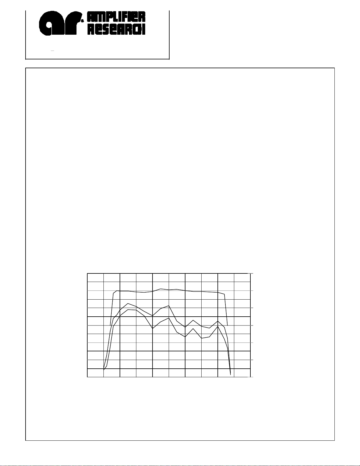
50S1G4A
Typical Performance
120
100
80
60
40
OUTPUT POWER (Watts)
20
0
0 1 2 3 4 5
3RD ORDER INTERCEPT POINT
LINEAR @ 3dB COMPRESSION
LINEAR @ 1dB COMPRESSION
FREQUENCY (GHz)
70
60
50
40
30
20
3RD ORDER INTERCEPT POINT (dBm)
10
Page 2
MISMATCH TOLERANCE
RATED POWER OUTPUT.................. 50 watts minimum
INPUT FOR RATED OUTPUT.................... 1.0 milliwatt
.................................................................................... maximum
POWER OUTPUT @ 3dB COMPRESSSION
Nominal................................................................... 70 watts
Minimum ................................................................. 50 watts
POWER OUTPUT @ 1dB COMPRESSION
Nominal................................................................... 60 watts
Minimum................................................................. 40 watts
FLATNESS .................................................... ±1.5 dB typical
..................................................................... ±2.0 dB maximum
FREQUENCY RESPONSE .......................... 0.8 – 4.2 GHz
.......................................................................... instantaneously
GAIN (at maximum setting)..................... 47 dB minimum
GAIN ADJUSTMENT.........................(Continuous Range)
..........................................................................10 dB minimum
................................................................... (4096 steps remote)
INPUT IMPEDANCE ............................................. 50 ohms
..............................................................VSWR 2.0:1 maximum
OUTPUT IMPEDANCE........................ 50 ohms, nominal
SPECIFICATIONS
Model 50S1G4A
100% of rated power without foldback. Will
operate without damage or oscillation with any
magnitude and phase of source and load
impedance. (See Application Note #27)
MODULATION CAPABILITY
Will faithfully reproduce AM, FM, or pulse
Modulation appearing on the input signal
THIRD ORDER INTERCEPT
See chart. The third order intercept points for
this chart have been determined using two tones
spaced 1 MHz apart. This is typical for WCDMA systems. Closer tone spacing such as 60
kHz generally provides about a 1db to 3db
improvement in the IP.
HARMONIC DISTORTION .........................Minus 20 dbc
...........................................................................max at 50 watts
SPURIOUS...............................................Minus 73 dbc Typ.
PHASE LINEARITY ................... ±± 1.0 deg/100 MHz, Typ
PRIMARY POWER.....................(Selected Automatically)
...............................................................90-132, 180-264 VAC
..............................................................50/60 Hz, single phase
...................................................................600 watts maximum
CONNECTORS
RF............................................................ Type N female
REMOTE INTERFACES
IEEE-488........................................................24 pin
RS-232 ..................................9 pin Subminiature D
SAFETY INTERLOCK................. 15 pin Subminiature D
COOLING......................... Forced air (self contained fans)
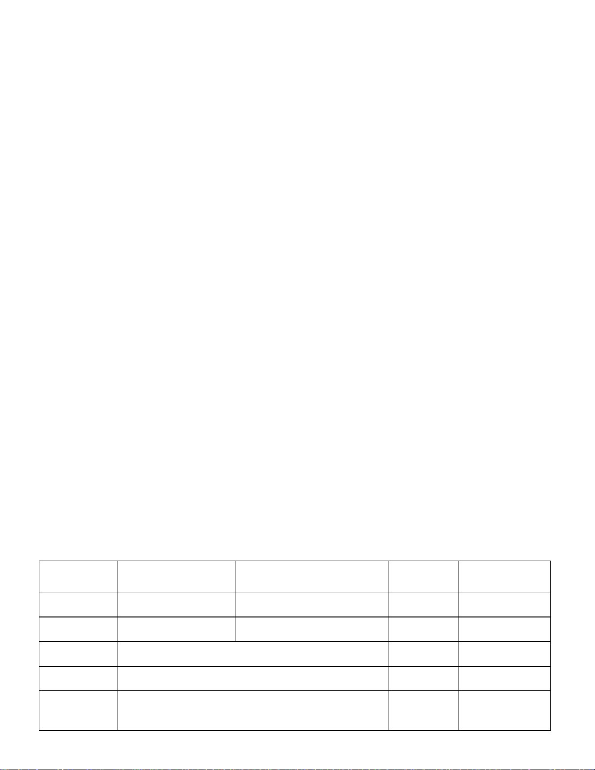
MODEL CONFIGURATIONS
MODEL
NUMBER
50S1G4A Type N female on front panel Type N female on front panel 45 kg (100 lbs)
50S1G4AM1 Type N female on rear panel Type N female on rear panel 45 kg (100 lbs)
50S1G4AM2 Same as 50S1G4A with enclosure removed for rack mounting 32 kg (71 lbs)
50S1G4AM3 Same as 50S1G4AM1 with enclosure removed for rack mounting 32 kg (71 lbs)
50S1G4AM4 Same as 50S1G4A optimized for improved linear power output and 3rd
order Intercept point from 1.7 to 2.7 GHz. The power output and gain
can be as much as 3dB lower than normal specification at 4.2 GHz
RF INPUT RF OUTPUT WEIGHT SIZE (W x H x D)
45kg (100 lbs)
50.3 x 24.9 x 54.6 cm
19.8 x 9.8 x 21.5 in
50.3 x 24.9 x 54.6 cm
19.8 x 9.8 x 21.5 in
48.3 x 22.2 x 54.6 cm
19.0 x 8.75 x 21.5 in
48.3 x 22.2 x 54.6 cm
19.0 x 8.75 x 21.5 in
50.3 x 24.9 x 54.6 cm
19.8 x 9.8 x 21.5 in
Page 3

 Loading...