

Page 1
160 School House Road, Souderton, PA 18964-9990 USA
Phone 215-723-8181•FAX 215-723-5688
MODEL 25A250A
25 WATTS CW
10 kHz - 250 MHz
The Model 25A250A amplifier is a self-contained, broadband unit designed for laboratory
applications where instantaneous bandwidth, high gain and moderate power output are required.
Utilization of push-pull MOSFET circuitry lowers distortion, improves stability and allows
operation into any load impedance without damage. The Model 25A250A, when used with an
RF sweep generator, will provide a minimum of 25 watts of swept power.
The Model 25A250A includes a front panel control which permits the operator to conveniently
set the amplifier's desired output level. Housed in a stylish contemporary enclosure, the Model
25A250A provides readily available RF power for typical applications such as RF susceptibility
testing, antenna and component testing, watt meter calibration, and use as a driver for higher
power amplifiers.
The 25A250A utilizes a switching power supply with universal and autoranging input which will
automatically accept from 90 to 135 VAC or from 180 to 270 VAC at 47 to 63 Hz.
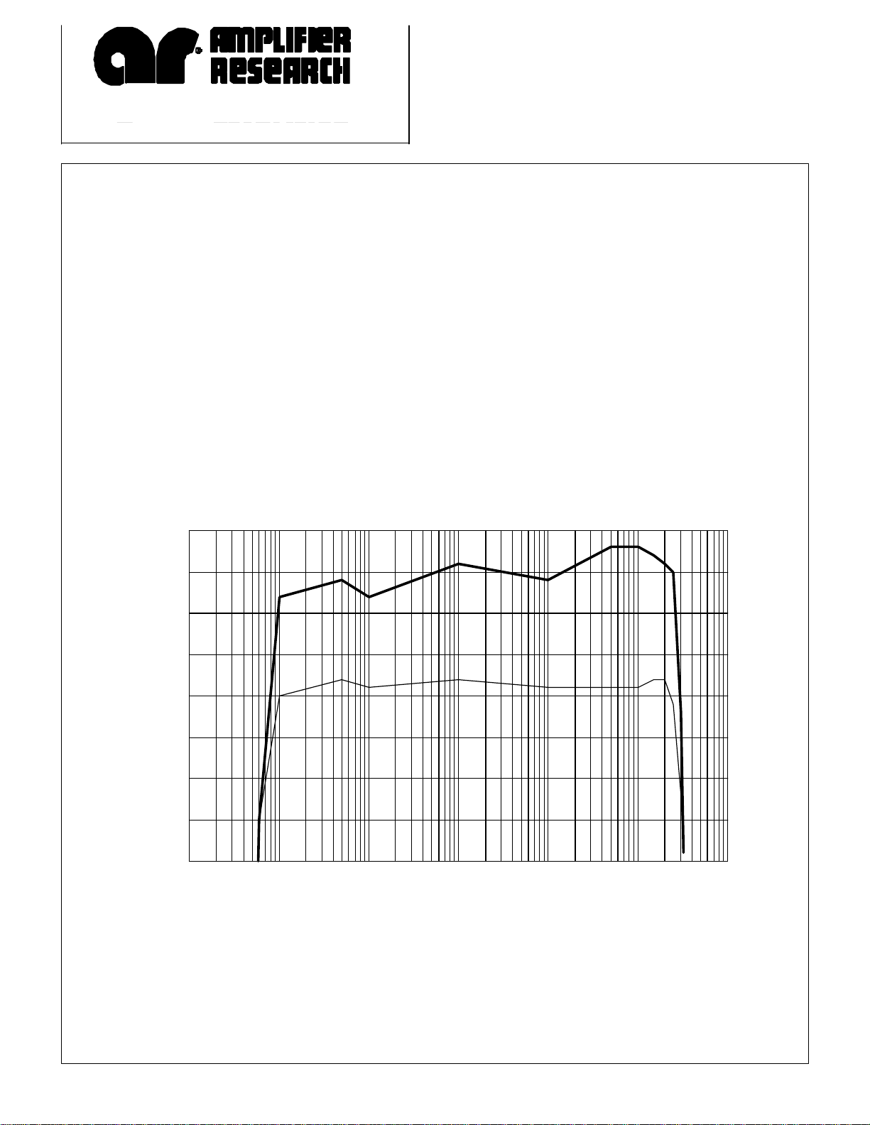
25A250A TYPICAL POWER OUTPUT
40
CW
30
LINEAR @ 1dB COMPRESSION
20
WATTS
10
0
0.001 0.01 0.1 1 10 100 1000
FREQUENCY (MHz)
REV102695
Page 2

SPECIFICATIONS
Model 25A250A
POWER OUTPUT, CW
Nominal......................................................................................35 watts
Minimum....................................................................................25 watts
Linear @ 1dB compression.......................................................15 watts minimum
FLATNESS....................................................................................±± 1.0 dB maximum
FREQUENCY RESPONSE.........................................................10 kHz - 250 MHz instantaneously
INPUT FOR RATED OUTPUT..................................................1.0 milliwatt maximum
GAIN (at maximum setting)........................................................44 dB minimum
GAIN ADJUSTMENT (continuous range)...............................18 dB minimum
INPUT IMPEDANCE..................................................................50 ohms, VSWR 1.5:1 maximum
OUTPUT IMPEDANCE..............................................................50 ohms, VSWR 2.0:1 maximum
MISMATCH TOLERANCE *.....................................................100% of rated power without foldback. Will operate
without damage or oscillation with any magnitude
and phase of source and load impedance.
MODULATION CAPABILITY...................................................Will faithfully reproduce AM, FM, or pulse modulation
appearing on the input signal
NOISE FIGURE (above 1.0 MHz).............................................6 dB typical
HARMONIC DISTORTION.......................................................Minus 20 dBc maximum at 15 watts
THIRD ORDER INTERCEPT POINT......................................54 dBm typical
PRIMARY POWER......................................................................90-135/180-270 VAC
47 to 63 Hz, single phase 200 watts maximum
RF CONNECTORS......................................................................Type N female
COOLING......................................................................................Forced air (self contained fans)
WEIGHT........................................................................................15.9 kg (35.0 lb)
SIZE (WxHxD) .............................................................................50.3 x 15.5 x 30.0 cm
19.8 x 6.1 x 11.80 in
* See Application Note #27
 Loading...