

Page 1
Model 20ST1G18A,
M1, M2
20 Watts CW
0.8-18 GHz
The Model 20ST1G18A is a self contained, forced air cooled, broadband hybrid solid state and traveling wave
tube (TWT) microwave amplifier designed for applications where wide instantaneous bandwidth, high gain and
moderate power output are required. A reliable amplifier system provides a conservative 20 watts minimum at
the amplifier output connector. Stated power specifications are at the fundamental frequency.
The amplifier's front panel digital display shows forward and reflected output plus extensive system status
information accessed through a series of menus via soft keys. Status indicators include power on, warm-up,
standby, operate, faults, excess reflected power warning and remote. Standard features include a built-in IEEE488 (GPIB) interface, 0dBm input, gain control, RF output sample port, VSWR protection for the TWT only, plus
monitoring of TWT helix current, cathode voltage, collector voltage, heater current, heater voltage, baseplate
temperature and cabinet temperature. The appropriate sub-band is user selected from either the front panel
menu or the GPIB interface. Modular design of the power supply and RF components allow for easy access
and repair. Use of switching mode power supplies result in significant weight reduction.
Housed in a stylish contemporary cabinet this unit is designed for benchtop use but can be removed from the
cabinet for rack mounting. The Model 20ST1G18A provides readily available RF power for a variety of
applications in Test and Measurement, (including EMC RF susceptibility testing), Industrial and University
Research and Development, and Service applications.
See Model Configuration for package alternatives.
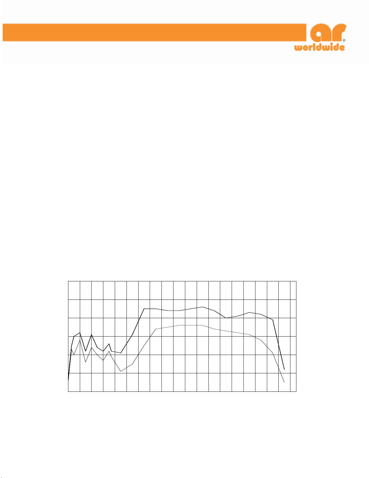
20ST1G18A TYPICAL POWER OUTPUT
60
CW
40
WATTS
20
0
0.5 2.5 4.5 6.5 8.5 10.5 12.5 14.5 16.5 18.5
LINEAR @ 1dB COMPRESSION
FREQUENCY (GHz)
ar worldwide • rf/microwave instrumentation 080405
160 School House Road Souderton, PA 18964-9990 • 215-723-8181 • www.ar-worldwide.com Page 1 of 2
Page 2

SPECIFICATIONS
Model 20ST1G18A
POWER (fundamental), CW, @ OUTPUT CONNECTOR
Nominal ................................................................30 watts
Minimum ...............................................................20 watts
Linear @ 1dB Compression ....................................10 watts minimum
FLATNESS.....................................................................±3 dB maximum 0.8 – 4.2 GHz
±9 dB maximum, 4.2 - 18 GHz
FREQUENCY RESPONSE ...............................................0.8 - 18 GHz in one of two selectable sub-bands
0.8 – 4.2 GHz and 4.2 - 18 GHz
INPUT FOR RATED OUTPUT ..........................................1.0 milliwatt maximum
GAIN (at maximum setting) ...........................................43 dB minimum
GAIN ADJUSTMENT (continuous range).........................10 dB minimum (0.8 – 4.2 GHz)
35 dB minimum (4.2 – 18 GHz)
INPUT IMPEDANCE.......................................................50 ohms, VSWR 2.0:1 maximum
OUTPUT IMPEDANCE ...................................................50 ohms, VSWR 2.5:1 typical
MISMATCH TOLERANCE...............................................100% of rated power without foldback from 0.8 – 4.2 GHz. Output power
foldback protection above 4.2 GHz at reflected power exceeding 20 watts. Will
operate without damage or oscillation with any magnitude and phase of source
and load impedance. May oscillate with unshielded open due to coupling to
MODULATION CAPABILITY...........................................Will faithfully reproduce AM, FM, or pulse modulation appearing on the input
NOISE POWER DENSITY (from 4.2 – 18 GHz)................Minus 80 dBm/Hz (maximum)
Minus 90 dBm/Hz (typical)
HARMONIC DISTORTION (at 20 watts)..........................0.8–4.2 GHz, Minus 20 dBc maximum, Minus 30 dBc typical
4.2-4.5 GHz; Minus 0 dBc maximum, Minus 1 dBc typical
4.5-5 GHz; Minus 1 dBc maximum, Minus 2 dBc typical
5-7 GHz; Minus 2.5 dBc maximum, Minus 4 dBc typical
7-10 GHz; Minus 5 dBc maximum, Minus 9 dBc typical
10-12 GHz; Minus 8 dBc maximum, Minus 12 dBc typical
Above 12 GHz; Minus 20 dBc maximum, Minus 30 dBc typical
PRIMARY POWER ..........................................................99-260 VAC
50/60 Hz single phase
700 VA maximum
CONNECTORS
RF input .................................................................Type N precision female on rear panel
RF output ...............................................................Type N precision female on rear panel
RF output sample port ............................................Type N precision female on rear panel
GPIB...................................................................... IEEE-488 female
Interlock ................................................................DB-15 female on rear panel
COOLING....................................................................Forced air (self contained fans), air entry and exit in rear.
E Must select one enclosure type from the following [E1
or E2 or E2S]:
E1 Removable outer enclosure, size 19.8 x11.7 x
27 in., 50.3 x 29.7 x 68.6 cm. Add approximately 30
lbs, 14 kg to weight of E2.
E2 Without outer enclosure size 19.0 x 10.5 x 27 in., 48.3
x 26.7 x 68.6 cm. Weight approximately 105 lbs, 48
kg.
E2S Enclosure removed for rack mounting: slides and front
handles installed, size same as E2. Add approximately
5 lbs, 2 kg to weight of E2.
input. Should not be tested with connector off.
signal. AM peak envelope power limited to specified power.
MODEL CONFIGURATION
Model Feature
20ST1G18A E1
20ST1G18AM1 E2
20ST1G18AM2 E2S
 Loading...