

Page 1

User’s Guide
ProSeries
High Power AC1750 Wi-Fi Access Point / Router
APR175P
Page 2

APR175P
USER’S GUIDE
1
CONTENTS
INTRODUCTION ........................................................... 4
GETTING STARTED ....................................................... 5
Package Contents ........................................................... 5
LED Indicators ................................................................. 6
Side Panel Description .................................................... 7
Mounting Instructions .................................................... 8
GETTING STARTED ....................................................... 9
OPERATIONAL MODES (BASIC SETUP) ........................ 10
ROUTER MODE ............................................................. 11
ACCESS POINT MODE .................................................... 22
WDS - ACCESS POINT MODE ........................................ 29
MANAGED ACCESS POINT MODE ................................. 36
ACCESS POINT CONTROLLER MODE ............................. 37
MORE SETTINGS ........................................................ 48
DASHBOARD ............................................................. 49
System Status................................................................ 49
Operational Mode ........................................................ 50
Basic Setup .................................................................... 51
Connected Devices ....................................................... 52
WDS Settings ................................................................ 53
WI-FI SETTINGS ..........................................................54
2.4GHz Status ................................................................ 54
2.4GHz Basic Settings .................................................... 55
2.4GHz Security ............................................................. 57
2.4GHz Output Power ................................................... 59
2.4GHz Site Survey ........................................................ 60
2.4GHz WDS .................................................................. 61
2.4GHz Access Schedule ................................................ 63
2.4GHz Advanced Settings ............................................ 64
5.0GHz Status ................................................................ 66
5.0GHz Basic Settings .................................................... 67
5.0GHz Security ............................................................. 69
5.0GHz Output Power ................................................... 71
5.0GHz Site Survey ........................................................ 72
5.0GHz WDS .................................................................. 73
5.0GHz Access Schedule ................................................ 75
5.0GHz Advanced Settings ............................................ 76
WPS Settings ................................................................. 78
MAC Address Filtering ................................................... 79
Page 3

APR175P
USER’S GUIDE
2
RADIUS Server ............................................................... 80
Internal RADIUS Server ................................................. 82
Radius Accounts ............................................................ 84
WMM / QoS .................................................................. 85
NETWORK SETTINGS .................................................. 86
Local Network (IPv4) ..................................................... 86
LAN Port Settings .......................................................... 87
VLAN ............................................................................. 89
Domain Redirect ........................................................... 90
Internet Network (WAN) IPv4 ....................................... 91
Advanced Settings ........................................................ 93
ADVANCED SETTINGS ................................................ 95
Port Forwarding ............................................................ 95
Port Filtering ................................................................. 96
DMZ (Demilitarized Zone) ............................................. 97
Denial of Service ........................................................... 98
IDS (Intrusion Detection System) .................................. 99
ADMINISTRATION ................................................... 100
System Status.............................................................. 100
Network Statistics ....................................................... 101
System Clock ............................................................... 102
Advanced Settings ...................................................... 103
System Logs ................................................................ 105
Alarm and LED Settings ............................................... 106
Upgrade Firmware ...................................................... 107
Save / Reload Settings ................................................. 109
Password Settings ....................................................... 110
ACCESS POINT CONTROLLER SETTINGS ..................... 111
DASHBOARD ............................................................... 115
System Status .............................................................. 115
Operational Mode ....................................................... 116
Basic Setup .................................................................. 117
Managed AP Overview ................................................ 118
Managed AP Map........................................................ 121
MANAGED AP STATUS................................................ 122
Access Points: Managed APs ....................................... 122
Access Points: Managed AP Groups ............................ 126
Wi-Fi Status: Active Wi-Fi Networks ........................... 129
Wi-Fi Status: Active Groups ........................................ 131
Connected Devices: Active Devices ............................. 132
AP Statistics ................................................................. 133
Managed AP Logs ........................................................ 134
Network Tools ............................................................. 135
Page 4

APR175P
USER’S GUIDE
3
MANAGED AP SETTINGS ............................................ 136
Access Points .............................................................. 136
Wi-Fi Settings .............................................................. 141
RADIUS Server Settings ............................................... 146
Access Control ............................................................ 148
Managed AP Map Edit ................................................ 150
Firmware Upgrade ...................................................... 151
LOCAL ACCESS POINT SETTINGS ............................... 152
TECHNICAL SPECIFICATIONS ..................................... 153
DEFAULT SETTINGS .................................................. 154
TROUBLESHOOTING & SUPPORT .............................. 155
WARRANTY & REGULATORY INFORMATION ............ 169
LEGAL NOTICES AND DISCLAIMERS………………….……..177
Page 5

APR175P
USER’S GUIDE
4
INTRODUCTION
Thank you for purchasing this Amped Wireless product. At Amped Wireless we strive to provide you with the
highest quality products through innovation and advanced technology. We pride ourselves on delivering
products that outperform the competition and go beyond your expectations. If you have any questions please
feel free to contact us. We’d love to hear from you and thank you for your support!
Email: sales@ampedwireless.com
Call: 888-573-8830
Web: www.ampedwireless.com
Page 6

APR175P
USER’S GUIDE
5
GETTING STARTED
Package Contents
Check to make sure you have all the contents within your package:
ProSeries High Power AC1750 Wi-Fi Access Point / Router
3 x Detachable High Gain 3dBi Antennas
Magnetic Mounting Kit & Mounting Template
Setup Guide
CD: User’s Guide
Ethernet Cable
Power Adapter
Page 7

APR175P
USER’S GUIDE
6
LED Indicators
From left to right:
PoE: Indicates when there is an active PoE connection on the LAN1 wired port. LED will remain on.
USB: Indicates when there is a USB device is attached to the USB port.
5.0GHz Wi-Fi: Blinks rapidly when Wi-Fi data traffic is transmitted or received over the wireless network.
2.4GHz Wi-Fi: Blinks rapidly when Wi-Fi data traffic is transmitted or received over the wireless network.
Wired Port 2: Indicates when a networking device is connected to wired port (LAN2) on the Access Point /
Router. The LED will blink rapidly when wired data traffic is transmitted or received.
Wired Port 1: Indicates when a networking device or modem is connected to wired port (LAN1 / WAN) on the
Access Point / Router. The LED will blink rapidly when wired data traffic is transmitted or received.
Status: Blinks when the Access Point / Router is booting up or resetting.
Power (PWR): Indicates when the Access Point / Router is powered on. The LED will remain on.
Page 8
APR175P
USER’S GUIDE
7
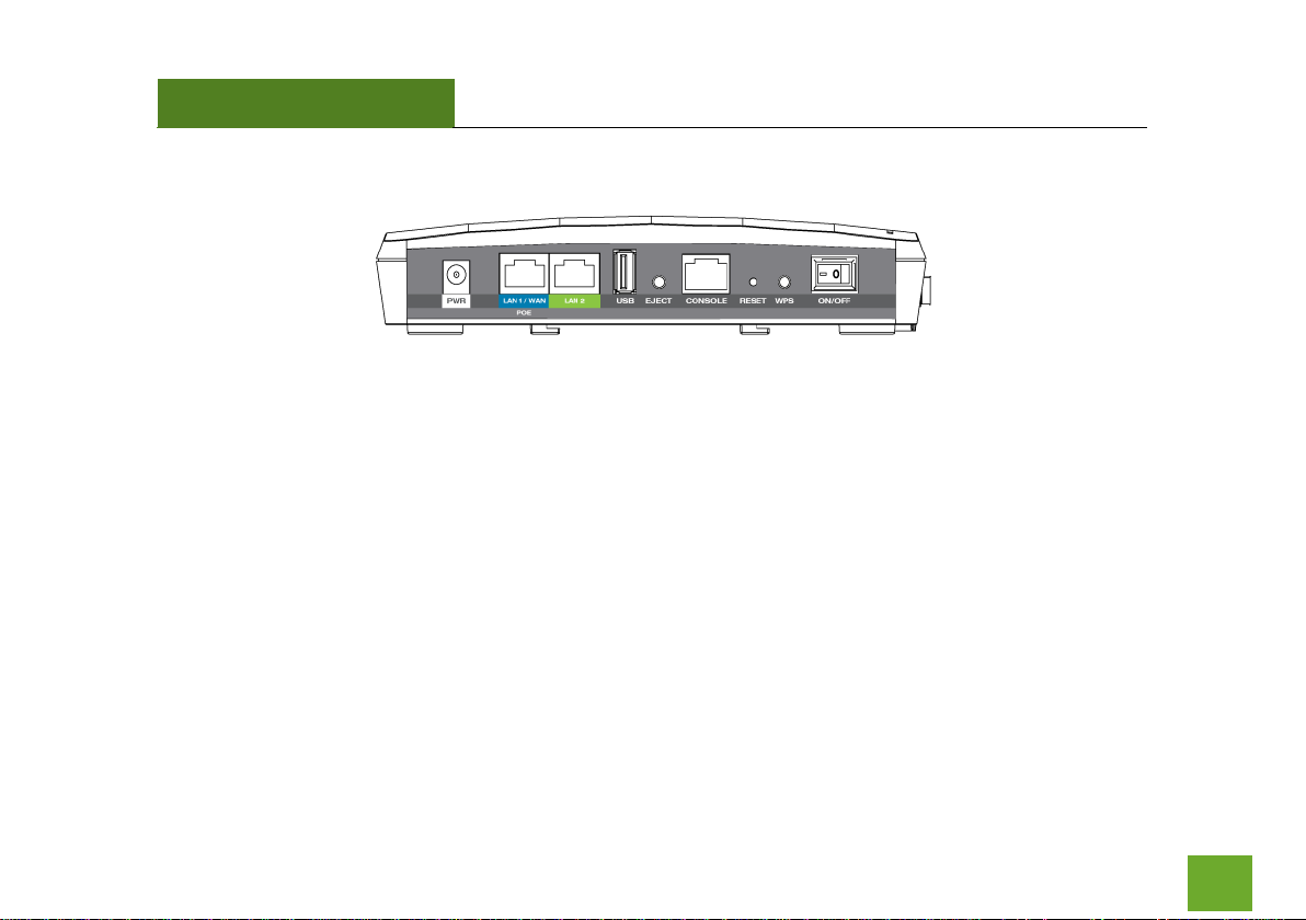
Side Panel Description
PWR: Power adapter port. 12V 4A.
LAN1 / WAN (PoE): Gigabit RJ-45 port with Power over Ethernet input. Connect wired devices or to a PoE
switch to use the Access Point without the power adapter. Functions as the port connected to your network
in Access Point modes and WAN port in Router mode.
LAN2: Gigabit RJ-45 local network port for expanding your network.
USB: Attach USB devices to save or load settings, upgrade firmware, save system logs or load boot files.
Eject: To safely eject an attached USB device.
Console: Connect to a management console for diagnostics. (i.e. HyperTerminal)
WPS: Enables Wi-Fi Protected Setup’s push button configuration.
On/Off: Device power on/off switch.
Page 9
APR175P
USER’S GUIDE
8
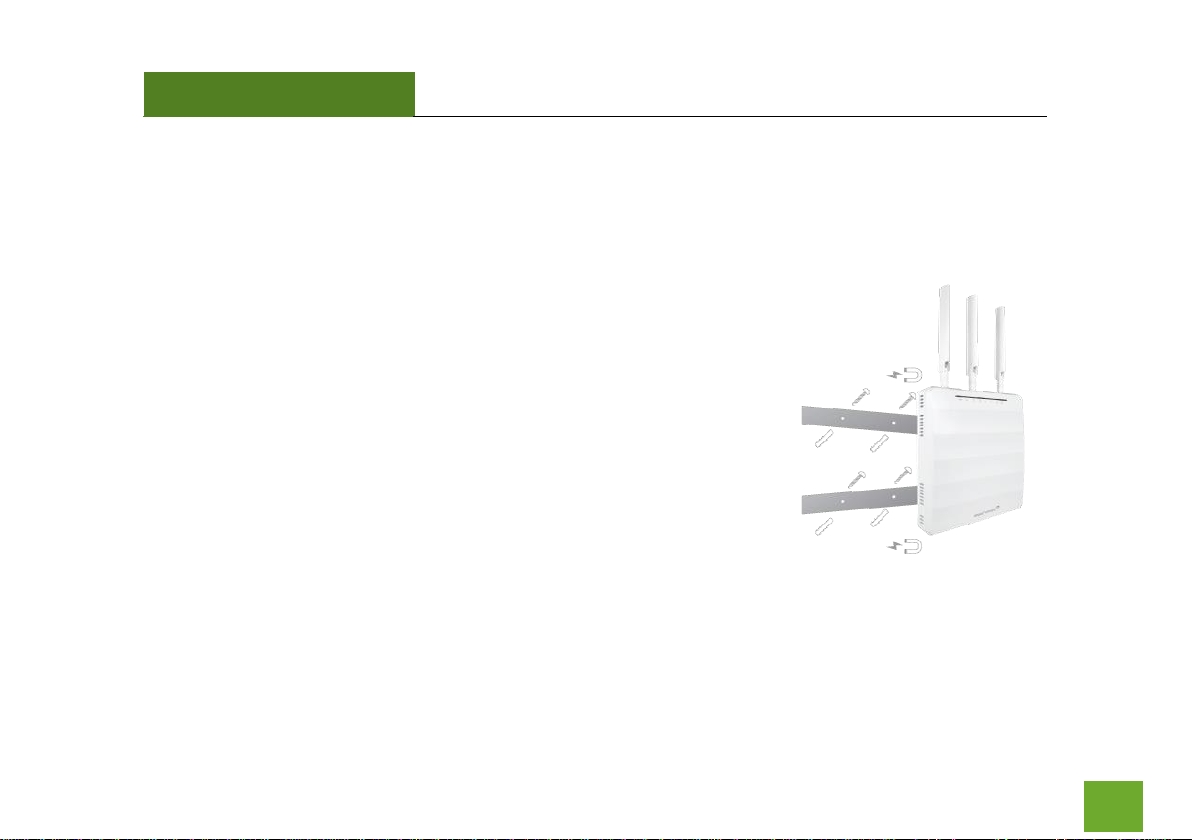
MOUNTING INSTRUCTIONS
Magnetic Mounting
The mounting kit included with the Access Point provides a convenient
method to mount the Access Point on a wall or ceiling. Once you have
chosen the location for where you want to install the Access Point, locate
the Mounting Template. Use it to mark the screw hole locations onto
your wall.
Once the screw holes have been marked, locate the Magnetic Mounting
Kit and use the included screws to fasten the two magnetic plates to the
wall.
Once the plates are fastened, attach the Access Point to the wall plates
and check that the magnets are firmly holding the Access Point to the
wall.
Wall Mounting
In addition to the Magnetic Mounting Kit, the Access Point can also be
mounted using the standard wall mounting clips on the bottom of the
device.
Page 10
APR175P
USER’S GUIDE
9
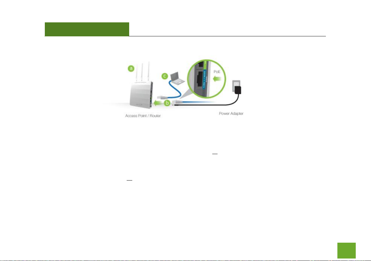
GETTING STARTED
a) Attach the included antennas to the antenna ports on the Access Point / Router.
b) Power on the Access Point / Router by attaching either the power adapter to the Access Point /
Router and plugging in the other end into a power outlet or attaching a PoE Ethernet cable to LAN1 /
WAN on the side panel and the other end to an active PoE switch.
c) Connect to the Access Point / Router with your computer by attaching an Ethernet cable to the LAN2
ports on the side panel or connect to the Access Point / Router’s Wi-Fi network: Amped_APR_2.4 or
Amped_APR_5.0. Password: wireless
Page 11

APR175P
USER’S GUIDE
10
OPERATIONAL MODES (BASIC SETUP)
The Access Point features five different operational modes that can be configured via the web menu:
- Router
- Access Point
- WDS Access Point
- Managed Access Point
- Access Point Controller
Page 12
APR175P
USER’S GUIDE
11
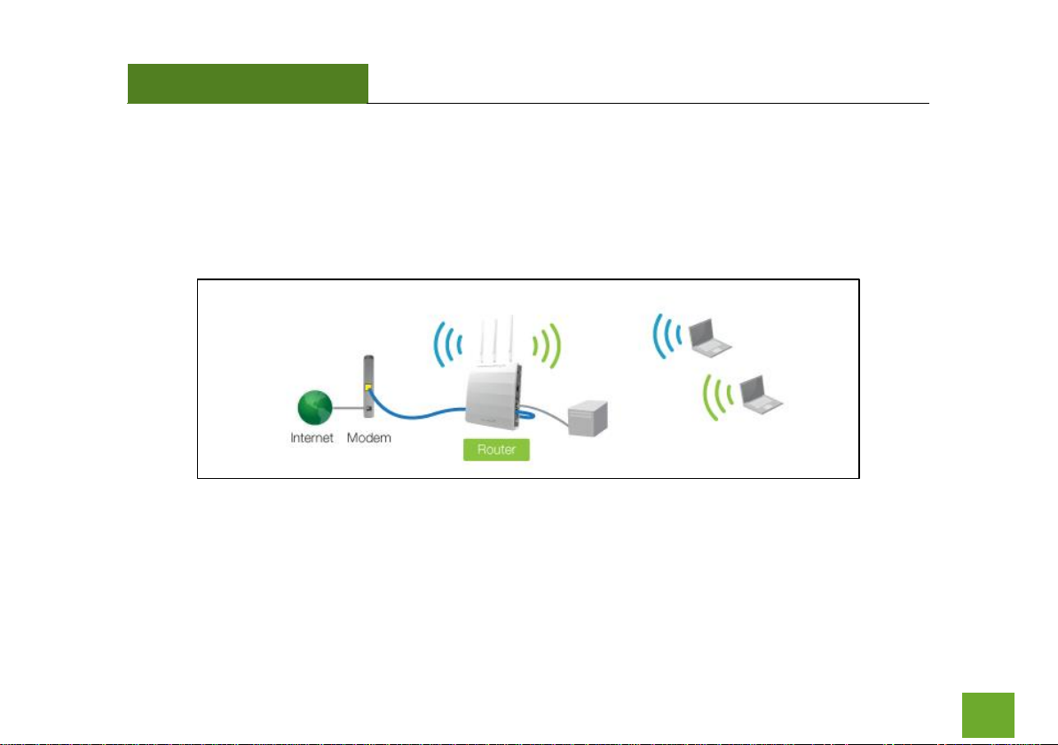
ROUTER MODE OVERVIEW
Share a single Internet connection via a connection to a broadband modem or other Internet source and
provide a secure firewall for your network. Router mode features 2.4GHz and 5.0GHz Wi-Fi connections as well
as one wired port for local wired devices and switches.
Page 13
APR175P
USER’S GUIDE
12
ROUTER MODE BASIC SETUP
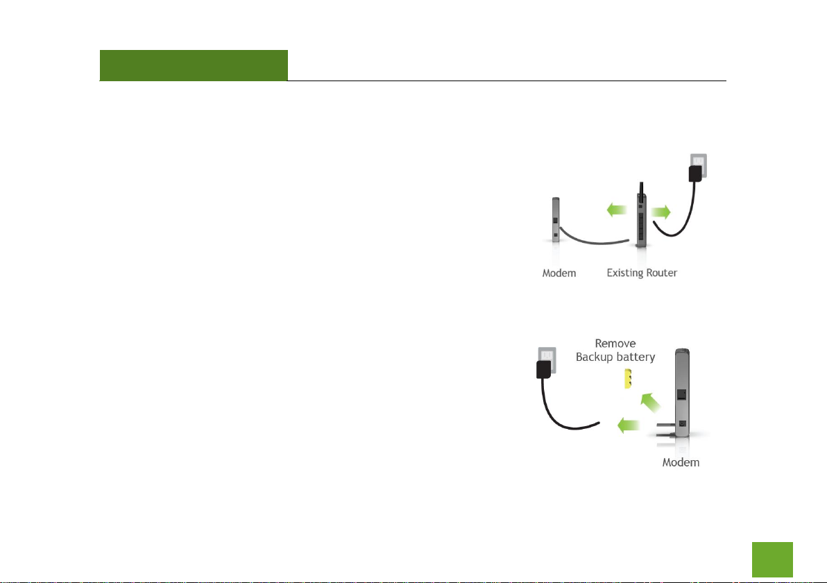
Setup Preparations
Disconnect and power off your existing router (if you have one).
Disconnect your existing router from your computer, your broadband
modem and its power outlet. If you do not have an existing router please
continue to the next step.
Power off your Modem
Power off the modem by disconnecting the modem’s power adapter
from the power outlet. If your modem has a backup battery, remove the
backup battery from your modem. Do NOT power on the modem until
prompted at a later step.
Page 14
APR175P
USER’S GUIDE
13
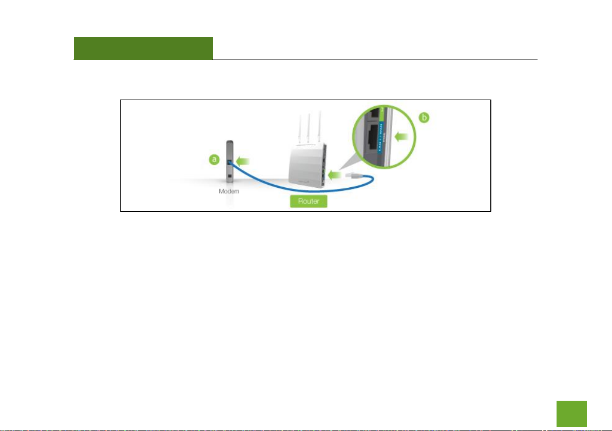
Connect the Router to your Modem
a) Use the included Ethernet cable and connect one end of the cable to your modem.
b) Connect the other end of the cable to the blue “Modem” port on the Router.
Page 15
APR175P
USER’S GUIDE
14
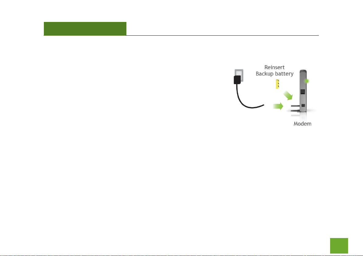
Power on your Modem
Plug in your modem’s power adapter and backup battery (if available):
Page 16
APR175P
USER’S GUIDE
15
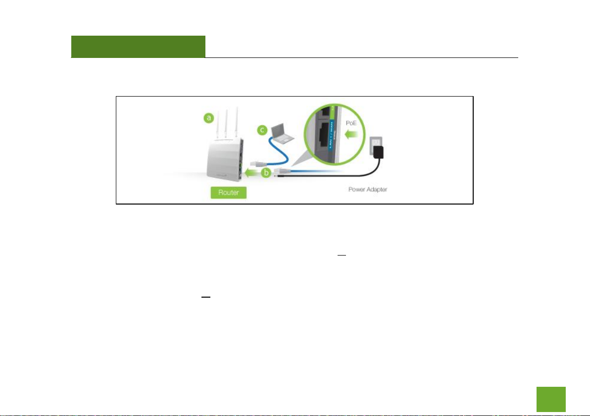
Attach Antennas, Power On & Connect to your Computer
a) Attach the included antennas to the antenna ports on the Access Point / Router.
b) Power on the Access Point / Router by attaching either the power adapter to the Access Point /
Router and plugging in the other end into a power outlet or attaching a PoE Ethernet cable to LAN1 /
WAN on the side panel and the other end to an active PoE switch.
c) Connect to the Access Point / Router with your computer by attaching an Ethernet cable to the LAN2
ports on the side panel or connect to the Access Point / Router’s Wi-Fi network: Amped_APR_2.4 or
Amped_APR_5.0. Password: wireless
Page 17
APR175P
USER’S GUIDE
16
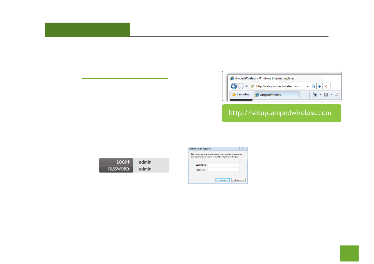
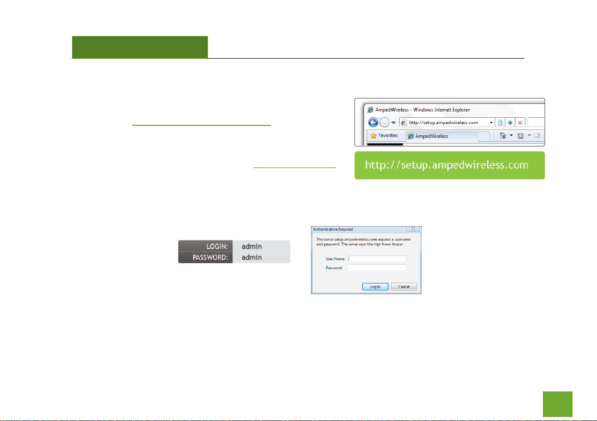
Open your Web Browser
a) Open your web browser.
b) Type http://setup.ampedwireless.com
into the web address bar.
c) If the web menu fails to open, type in the following IP
address into your web address bar: http://192.168.80.1
If you have problems accessing the Web Menu… Disable third-party
firewalls such as Norton, Zone Alarm or Windows Defender. Check to
see that your computer is not connected to other wireless networks.
d) When prompted, enter the login and password:
Page 18
APR175P
USER’S GUIDE
17
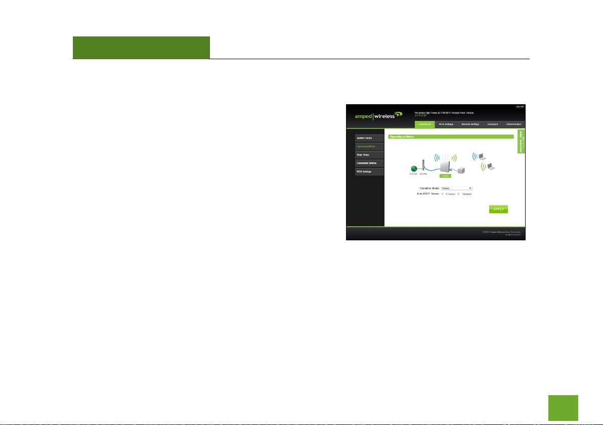
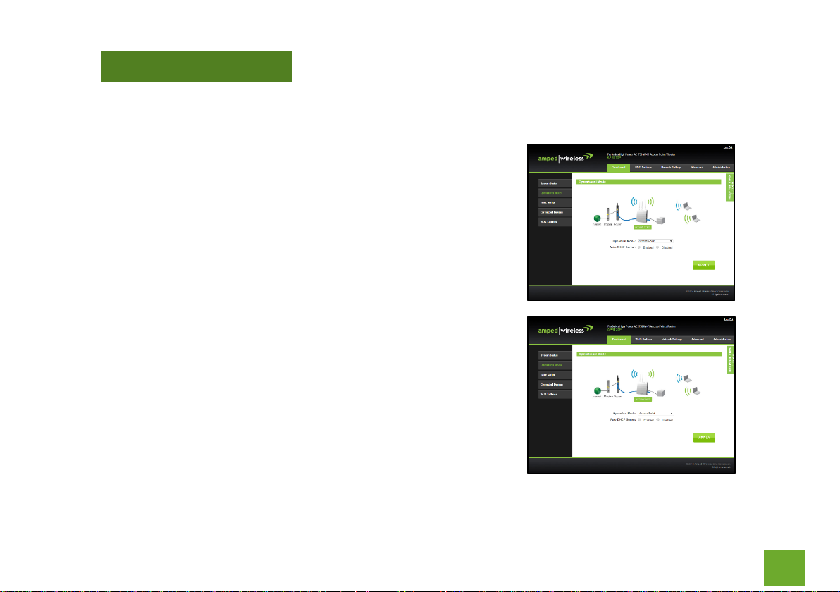
Select the Operational Mode
a) After the web menu appears, select Dashboard from
the navigation menu on the top of the page.
b) Select Operational Mode from the left hand
navigation.
c) Using the dropdown menu, select Router Mode for
the Operational Mode and click Apply.
d) When the web menu has reloaded, select Basic Setup.
Page 19
APR175P
USER’S GUIDE
18
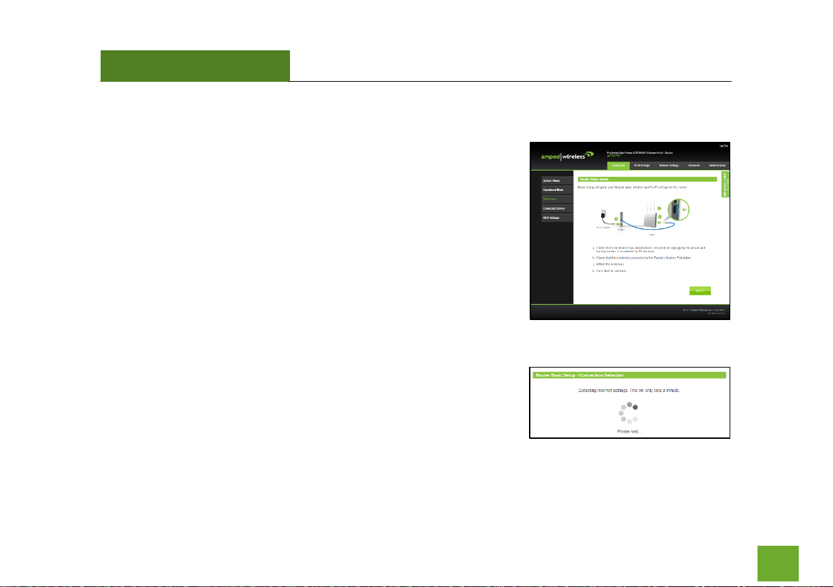
Basic Setup Wizard
Confirm that your hardware is correctly connected and Click Next to
begin.
Internet Connection Detection
The Wizard will try to detect your Internet settings and configure the
router. Please be patient.
Page 20
APR175P
USER’S GUIDE
19
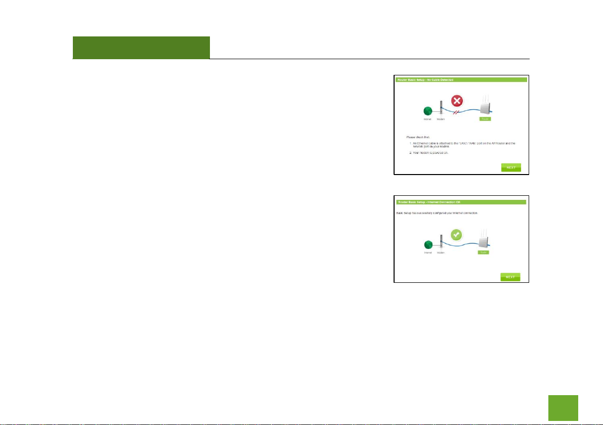
If there was a problem with the Automatic Configuration, the wizard will
notify you of the issue. If you continue to have problems, contact our
support department at 888-573-8820.
If the Internet connection detection was successful, you will see a green
check. Click Next to continue.
Page 21
APR175P
USER’S GUIDE
20
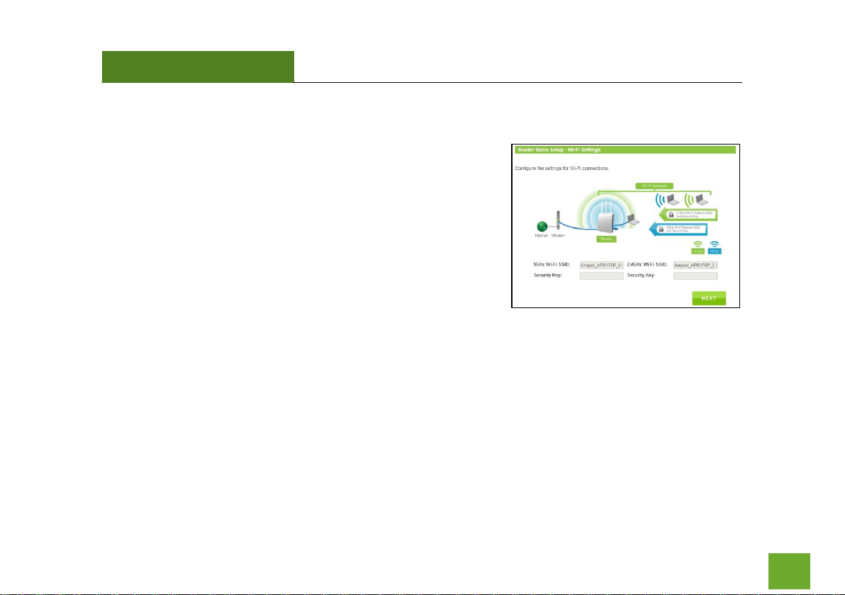
Wi-Fi Settings
The default ID of your 5.0GHz Wi-Fi network and 2.4GHz Wi-Fi
network is:
Amped_APR_5.0
Amped_APR_2.4
To change it, enter a new name in the SSID field. Users connecting
wirelessly to the Router will use these IDs to identify your wireless
network.
The default Security Key (WPA/WPA2) for your Wi-Fi networks is “wireless”.
To change them, enter a new key in the Security Key field for both 2.4GHz and 5.0GHz networks. The keys
must be 8-characters minimum.
Click Next to apply your settings.
Page 22
APR175P
USER’S GUIDE
21
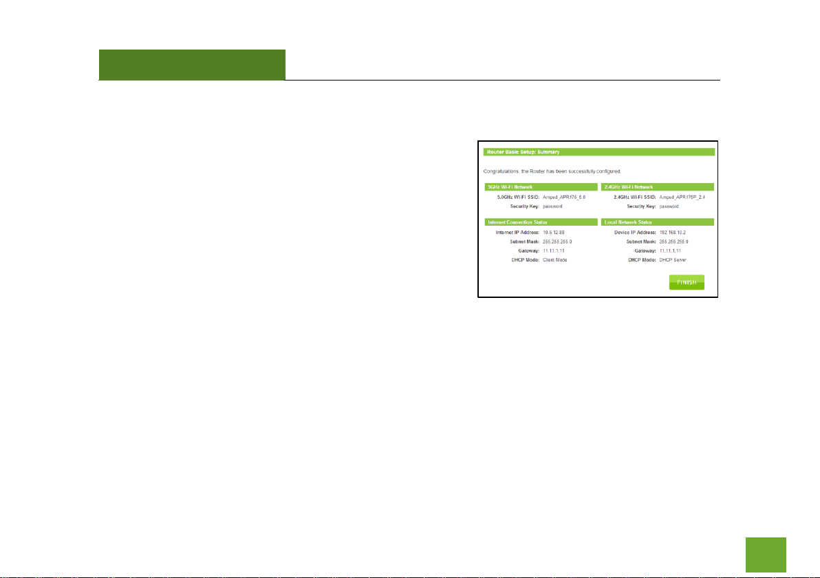
Setup Summary
Once the Router has rebooted, it will load the Setup Summary
page and provide you with the details of your setup. It is
recommended that you print this page for your records.
Open a new web browser window and check that you have
access to the Internet.
Additional settings can be configured using the navigation menu
on the top of the Web Menu.
Page 23
APR175P
USER’S GUIDE
22
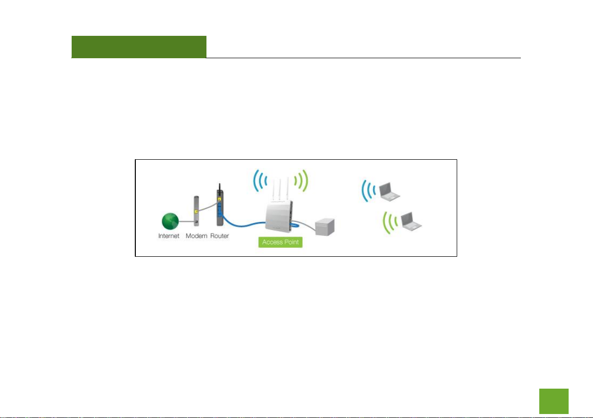
ACCESS POINT MODE OVERVIEW
Access Point mode creates a new Wi-Fi network for users to connect to by connecting to a local port on your
network (i.e. via a network switch or local router network port). Devices connected to the Access Point are on
the same network as the router and have the ability to access files from devices on the same network. Access
Point mode provides both 2.4GHz and 5GHz Wi-Fi connections.
Page 24
APR175P
USER’S GUIDE
23
ACCESS POINT MODE BASIC SETUP
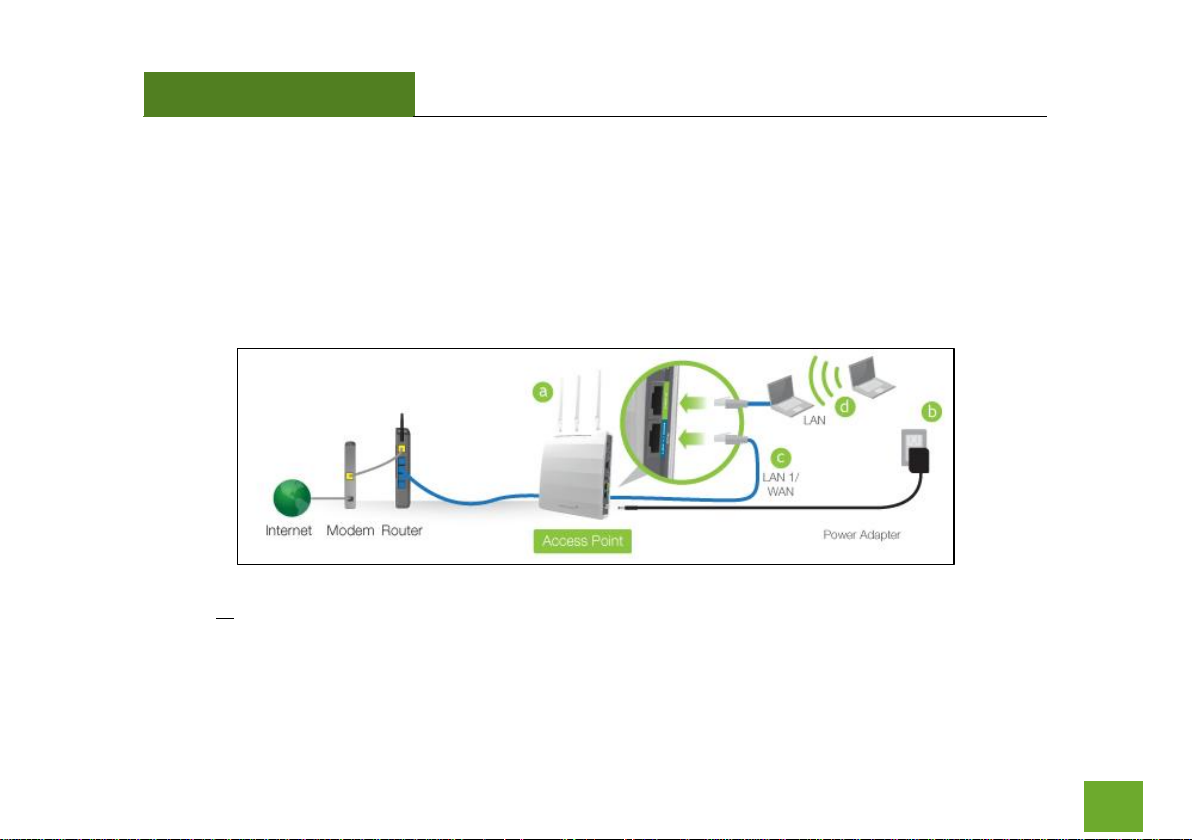
Connect the Access Point to your Router/Network:
a) Attach the antennas to the Access Point.
b) Plug in the Power Adapter.
c) Using the included RJ-45 Ethernet cable, attach one end to the Access Point’s LAN 1/WAN port and
the other to your router’s network port (or any available port on a network switch).
d) Connect an Ethernet cable between the Access Point’s LAN2 port and your computer’s network port
or connect to the Access Point’s Wi-Fi Network: Amped_APR_2.4 or Amped_APR_5.0, Password:
wireless.
Page 25
APR175P
USER’S GUIDE
24
Open your Web Browser
a) Open your web browser.
b) Type http://setup.ampedwireless.com
into the web address bar.
c) If the web menu fails to open, type in the following IP
address into your web address bar: http://192.168.80.1
If you have problems accessing the Web Menu: Disable third-party
firewalls such as Norton, Zone Alarm or Windows Defender. Check to
see that your computer is not connected to other wireless networks.
d) When prompted, enter the login and password:
Page 26
APR175P
USER’S GUIDE
25
Select the Operational Mode
a) After the web menu appears, select Dashboard from the
navigation menu on the top of the page.
b) Select Operational Mode from the left hand navigation.
c) Using the dropdown menu, select Access Point Mode for the
Operational Mode and click Apply.
d) When the web menu has reloaded, select Basic Setup.
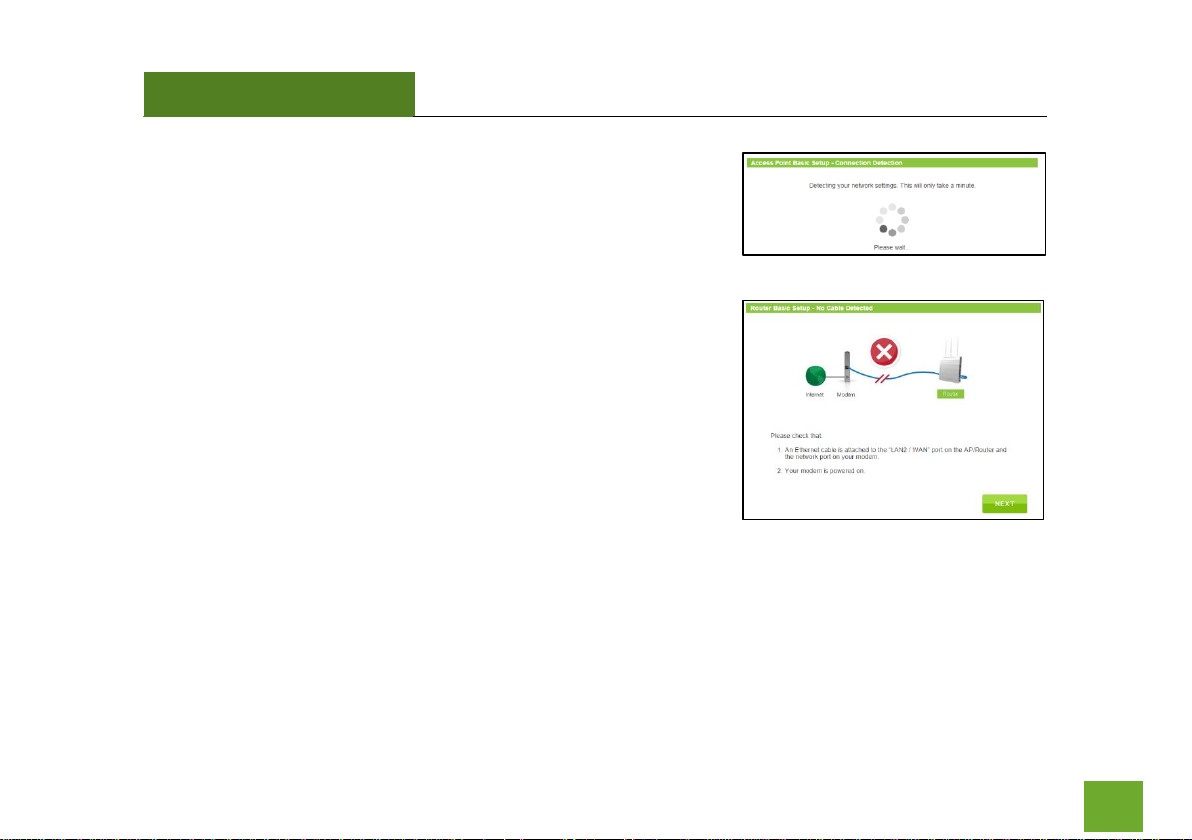
Basic Setup Wizard
Confirm that your hardware is correctly connected and Click Next to
begin.
Page 27
APR175P
USER’S GUIDE
26
Basic setup will detect your network settings and automatically
configure the Access Point to your network.
If there was a problem with the configuration, Basic Setup will notify
you of the issue. If you continue to have problems, contact our support
department at 888-573-8820.
Click Next to continue.
Page 28
APR175P
USER’S GUIDE
27
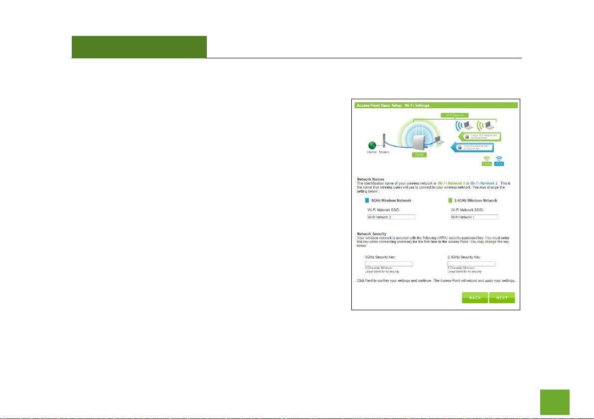
Wi-Fi Settings
The default Wi-Fi network ID of your 5GHz Wi-Fi network and
2.4GHz Wi-Fi network is:
Amped_APR_5.0
Amped_APR_2.4
To change it, enter a new name in the SSID field. Users
connecting wirelessly to the Access Point will use these IDs to
identify your wireless network.
The default Security Key (WPA/WPA2) for your Wi-Fi networks is
“wireless”.
To change them, enter a new key in the Security Key field for both
2.4GHz and 5GHz networks. The keys must be 8-characters
minimum.
Click Next to apply your settings.
Page 29
APR175P
USER’S GUIDE
28
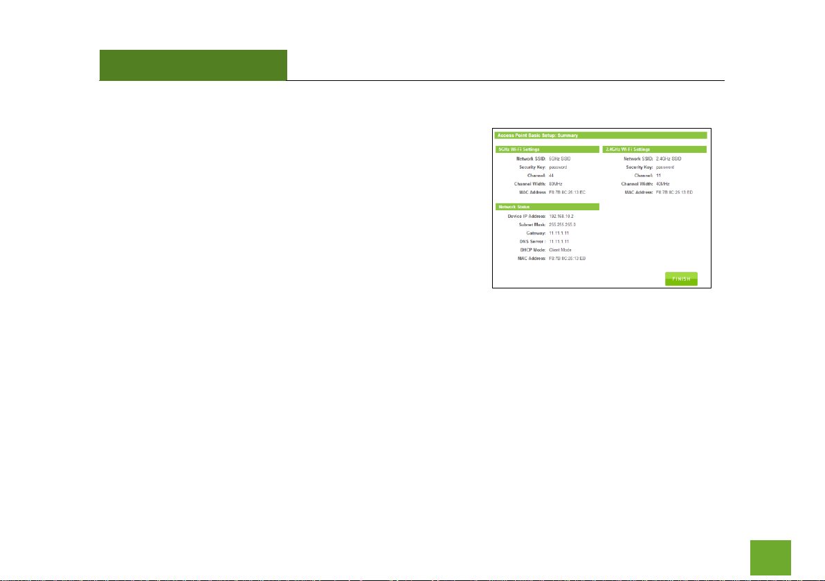
Setup Summary
Once the Access Point has rebooted, it will load the Setup
Summary page and provide you with the details of your setup. It is
recommended that you print this page for your records.
Open a new web browser window and check that you have access
to the Internet.
Additional settings can be configured using the navigation menu
on the top of the Web Menu.
Page 30
APR175P
USER’S GUIDE
29
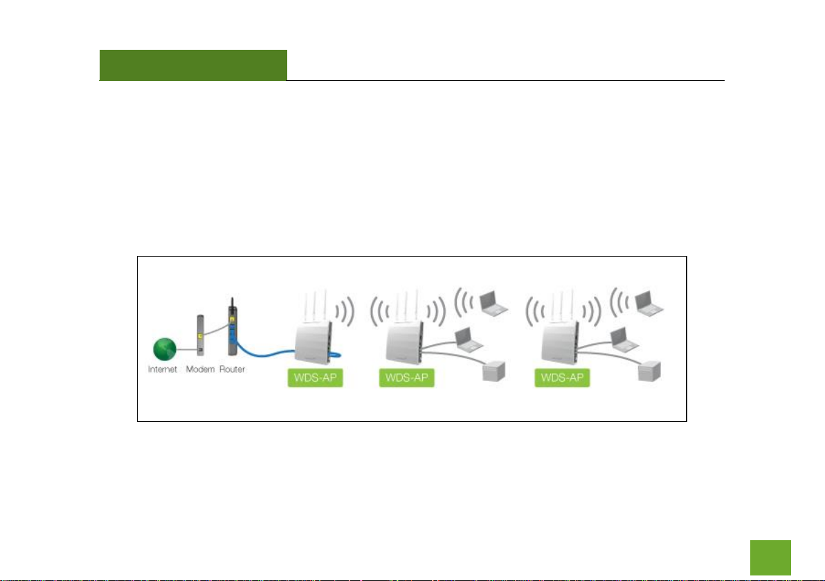
WDS – ACCESS POINT MODE (WPS-AP) OVERVIEW
WDS (Wireless Distribution System) Access Point mode enables the wireless interconnection of Access Points.
Access Points traditionally connect to the network via a cable (see Access Point Mode), however in WDSAccess Point mode, Access Points connect to the network wirelessly and create a wireless or wired network for
devices to connect to. WDS-Access Point mode allows for multiple WDS-Access Points to be set up on a
network. They function similar to that of a range extender or repeater.
Page 31

APR175P
USER’S GUIDE
30
WDS – ACCESS POINT MODE (WPS-AP) BASIC SETUP
Connect the Access Point to your Router/Network:
a) Attach the antennas to the Access Point.
b) Plug in the Power Adapter.
c) Using the included RJ-45 Ethernet cable, attach one end to the Access Point’s LAN 1/WAN port and
the other to your router’s network port (or any available port on a network switch).
d) Connect an Ethernet cable between the Access Point’s LAN2 port and your computer’s network port
or connect to the Access Point’s Wi-Fi Network: Amped_APR_2.4 or Amped_APR_5.0, Password:
wireless.
Page 32

APR175P
USER’S GUIDE
31
Open your Web Browser
a) Open your web browser.
b) Type in: http://setup.ampedwireless.com
into the web address bar.
c) If the web menu fails to open, type in the following IP
address into your web address bar: http://192.168.80.1
If you have problems accessing the Web Menu: Disable third-party
firewalls such as Norton, Zone Alarm or Windows Defender. Check to
see that your computer is not connected to other wireless networks.
d) When prompted, enter the login and password:
Page 33

APR175P
USER’S GUIDE
32
Select the Operational Mode
a) After the web menu appears, select Dashboard from the
navigation menu on the top of the page.
b) Select Operational Mode from the left hand navigation.
c) Using the dropdown menu, select WDS - Access Point Mode
for the Operational Mode and click Apply.
d) When the web menu has reloaded, select Basic Setup.
Basic Setup Wizard
Using the dropdown menu select which Wi-Fi frequency you wish to
configure for WDS - AP mode:
- 2.4GHz only, 5GHz only, or both 2.4GHz and 5GHz.
After you have made your selection, click Next to begin.
For the purpose of this User’s Guide, we will provide instructions and
screenshots for a dual band configuration (both 2.4GHz and 5GHz).
Page 34

APR175P
USER’S GUIDE
33
WDS Settings
WDS - AP mode requires additional Access Points also functioning in
WDS - AP mode. Each WDS enabled Access Point connects to the
other via MAC addresses. Enter the MAC addresses of the Access
Points with WDS enabled into the corresponding fields that you wish
to connect to.
For WDS connections to work properly, the MAC address
associations must also be configured on each individual WDS
enabled Access Point, not just the one you are currently configuring.
For example, if you are connecting three WDS-APs, AP 1 must have
AP 2 and AP 3’s MAC address conifgured, while AP 2 has AP 1’s and
AP 3’s MAC, and AP 3 has AP 1’s and AP 2’s MAC configured.
Encryption can be used to secure your WDS connections. If you
choose to use encryption (recommended), it is important that you
set the same security key setting on all connected WDS enabled
Access Points. Click Next to continue.
Page 35

APR175P
USER’S GUIDE
34
Wi-Fi Settings
In addition to interconnecting Access Points, WDS-AP mode allows for
Wi-Fi connections to the Access Point from Wi-Fi devices such as a PC
or tablet.
The default Wi-Fi ID’s of your 5GHz Wi-Fi network and 2.4GHz Wi-Fi
network are:
Amped_APR_5.0
Amped_APR_2.4
To change it, enter a new name in the SSID field. Users connecting wirelessly to the Access Point will use these
IDs to identify your wireless network.
The default Security Key (WPA/WPA2) for your Wi-Fi networks is “wireless”.
To change them, enter a new key in the Security Key field for both 2.4GHz and 5.0GHz networks. The keys
must be 8-characters minimum.
Click Next to apply your settings.
Page 36

APR175P
USER’S GUIDE
35
Setup Summary
Once the Access Point has rebooted, it will load the Setup
Summary page and provide you with the details of your setup. It
is recommended that you print this page for your records.
The Summary will display the status of each WDS connection and
the signal strength of each connection. Connections with lower
signal strength connections may perform slower. It is
recommended to have a signal of at least 70% for the best
performance.
Additional settings can be configured using the navigation menu
on the top of the Web Menu.
Page 37

APR175P
USER’S GUIDE
36
MANAGED ACCESS POINT MODE OVERVIEW
Managed Access Point mode functions similarly to Access Point mode however the majority of settings of the
Access Point are managed remotely from a single designated Access Point Controller. This mode is typically
used for deployments where multiple Access Points are installed and configuring all devices simultaneously is
more convenient. Because Managed Access Points are not configured directly, there is no Basic Setup for
Managed Access Points.
Page 38

APR175P
USER’S GUIDE
37
ACCESS POINT CONTROLLER MODE OVERVIEW
Access Point Controller mode creates a master Access Point to manage all Access Points (up to 7
simultaneously) that are functioning in Managed Access Point mode (Access Point Controllers cannot manage
other devices in Router mode, Access Point mode or WDS-Access Point mode). The Access Point Controller
provides a single web based interface to manage the Wi-Fi SSID, security, VLAN, group settings, firmware
upgrades and much more for all Managed Access Points. Settings can be applied at once to all devices or
individually for each one.
The AP Controller has the following management topology:
The AP Controller can configure settings of Managed Access Points (up to 7)
A Managed Access Point can belong to a single Access Point Group
An Access Point Group can have a 2.4GHz WLAN Group and a 5.0GHz WLAN Group
Each WLAN Group can have up to 16 unique WLAN networks or SSIDs
Page 39

APR175P
USER’S GUIDE
38
ACCESS POINT CONTROLLER MODE BASIC SETUP
Connect the Access Point to your Router/Network:
a) Attach the antennas to the Access Point.
b) Plug in the Power Adapter.
c) Using the included RJ-45 Ethernet cable, attach one end to the Access Point’s LAN 1/WAN port and
the other to your router’s network port (or any available port on a network switch).
d) Connect an Ethernet cable between the Access Point’s LAN2 port and your computer’s network port
or connect to the Access Point’s Wi-Fi Network: Amped_APR_2.4 or Amped_APR_5.0, Password:
wireless.
Page 40

APR175P
USER’S GUIDE
39
Open your Web Browser
a) Open your web browser.
b) Type http://setup.ampedwireless.com
into the web address bar.
c) If the web menu fails to open, type in the following IP
address into your web address bar: http://192.168.80.1
If you have problems accessing the Web Menu… Disable third-party
firewalls such as Norton, Zone Alarm or Windows Defender. Check to
see that your computer is not connected to other wireless networks.
d) When prompted, enter the login and password:
Page 41

APR175P
USER’S GUIDE
40
Select the Operational Mode
a) After the web menu appears, select Dashboard from the
navigation menu on the top of the page.
b) Select Operational Mode from the left hand navigation.
c) Using the dropdown menu, select Access Point Controller
Mode for the Operational Mode and click Apply.
d) When the web menu has reloaded, select Basic Setup.
Page 42

APR175P
USER’S GUIDE
41
Basic Setup Wizard
Before we begin please check that:
a) All Managed Access Points are powered on.
b) All Managed Access Points are set to “Managed Access Point”
operational modes. If they are not please do so from the Web
Menu for each Access Point.
c) All Managed Access Points are connected to the same physical
network as the Access Point Controller. If your Access Points are
on different networks or if there is a firewall or network
protocols blocking communication between the Access Points, Basic Setup will not be able to discover
the Access Points to configure them. Please make sure all Access Points are on the same network.
Click Next to begin.
Page 43

APR175P
USER’S GUIDE
42
Managed Access Point Detection
Basic setup will scan for all available Managed Access
Points on your network. This may take a minute.
Once complete a list of available Managed Access Points
will appear. Select the Access Points that you wish to
configure. You may select and configure up to seven
Managed Access Points total. All of the Access Points you
select will be configured with the same Wi-Fi settings.
Once selected, click Next.
After configuring the Wi-Fi settings for the first set of
Access Points, you can come back to this page to select a
second group of Access Points to configure with a
different set of Wi-Fi settings. Alternatively, you may also
skip this step and Basic Setup will take you to the configuration page for the AP Controller’s Wi-Fi settings.
Page 44

APR175P
USER’S GUIDE
43
Each Managed Access Point will have a Status displayed on the right side.
Below is a legend for each status color:
Disconnected (Grey): The Access Point cannot be reached and is not available or disconnected from the
network.
Error (Red): The AP Controller could not connect with the Access Point. This can be because of several
reasons such as an authentication error or an incompatible management protocol.
Busy (Orange): The AP Controller is in the process of configuring the Access Point.
Connecting (Yellow): The AP Controller is attempting to connect to the Access Point. This includes the
authentication process of the Access Point to the AP Controller
Connected (Green): The AP Controller has successfully authenticated and connected to the Access Point.
Waiting Association (Blue): The Access Point has not yet been selected for management by the AP
Controller.
Page 45

APR175P
USER’S GUIDE
44
Wi-Fi Settings
Configure Wi-Fi settings (Primary and secondary network SSIDs and
security) for the group of selected Managed Access Points from this
page. The Access Points will all have the same settings. You can also
configure the device name for each Access Point.
The default Wi-Fi ID for 5.0GHz and 2.4GHz networks is:
Amped_APR_5.0 and Amped_APR_2.4
To change it, enter a new name in the SSID field. Users connecting
wirelessly to the Access Point will use these IDs to identify your
wireless network.
The default Security Key (WPA/WPA2) for your Wi-Fi networks is “wireless”.
To change them, enter a new key in the Security Key field for both 2.4GHz and 5.0GHz networks. The keys
must be 8-characters minimum.
Page 46

APR175P
USER’S GUIDE
45
Once complete, you can choose to click Apply to apply the settings and choose a new group of Managed
Access Points to configure with new settings.
If you are finished, and have no other Managed Access Points to configure, click Next to continue to Wi-Fi
Settings for the Access Point Controllers own Wi-Fi network.
If you make a mistake or wish to reselect a group of Managed Access Points, click Cancel to return the
detected Access Point list.
Page 47

APR175P
USER’S GUIDE
46
Wi-Fi Settings: AP Controller’s Local Wi-Fi
The Access Point Controller also features its own Wi-Fi networks. By
default the Access Point Controller’s Wi-Fi networks are disabled to
optimize the performance of the Access Point Controller’s
management functions. You can enable them here, however, during
heavy usage, this may negatively impact the performance of the
Access Point Controller.
The AP Controller’s default Wi-Fi ID for 5.0GHz & 2.4GHz networks is:
Amped_APR_5.0 and Amped_APR_2.4
To change it, enter a new name in the SSID field. Users connecting wirelessly to the Access Point will use these
IDs to identify your wireless network.
The default Security Key (WPA/WPA2) for your Wi-Fi networks is “wireless”.
Click Next when done to complete the Basic Setup wizard.
Page 48

APR175P
USER’S GUIDE
47
Setup Summary
Once the Access Point has rebooted, it will load the Setup Summary page and
provide you with the details of your setup. It is recommended that you print this
page for your records.
The Summary will display the Wi-Fi settings and groups of Managed Access Points
using those Wi-Fi settings. If you have configured different Wi-Fi settings for
multiple Managed Access Points, scroll down to view the details of each setting.
Additional settings can be configured using the navigation menu on the top of the
Web Menu.
When configuring settings for Managed Access Points, it is important to
understand the Controller’s management topology:
1) The AP Controller can configure settings of Managed Access Points (up to 7)
2) A Managed Access Point can belong to a single Access Point Group
3) An Access Point Group can have a 2.4GHz WLAN Group and a 5.0GHz WLAN Group
4) Each WLAN Group can have up to 16 unique WLAN networks or SSIDs
Page 49

APR175P
USER’S GUIDE
48
MORE SETTINGS
The Access Point has many additional features and settings that can be configured via the Web Menu. To
access these settings start with the navigation menu located on the top of the Web Menu. Once the desired
menu is selected, additional navigational options will appear on the left hand side. Select the sub menus from
here to access the specific settings for each option.
Note: Not all settings and features are available for all operational modes. As you change from one
operational mode to another some features and settings will be greyed out and cannot be accessed as they do
not apply to the selected operational mode.
Page 50

APR175P
USER’S GUIDE
49
DASHBOARD
Dashboard: System Status
The Dashboard System Status will provide you with the current status of the
Access Point. It provides you with glance at general setup information such as
the current operational mode, firmware version and uptime of the Access
Point. From here you can quickly change the operational mode by clicking the
“Change” button to the right of the operational mode.
In addition to the operational mode, the System Status also provides you with
information regarding your Internet or WAN port connection, if available for
your operational mode, as well as the details for your local network.
Information regarding your primary 2.4GHz and 5.0GHz Wi-Fi networks are displayed in the lower half of the
page. Note, this section only shows details for the first SSID of each frequency. For information on additional
SSIDs, click “View Details”.
At the bottom of the page you will find details about the Wired Port settings.
Page 51

APR175P
USER’S GUIDE
50
Dashboard: Operational Mode
The Operational Mode page lets you change the operating mode of the Access Point. As described earlier, the
Access Point features five different modes:
- Router
- Access Point
- WDS Access Point
- Managed Access Point
- Access Point Controller
From this page you can view your current operational mode or change the
operational mode to any of the modes above. For descriptions on the features of each mode please see the
operational mode overviews described in the Operational Modes (Basic Setup) section of this User’s Guide.
Selecting an operational mode from the dropdown menu will also provide you with a diagram and overview of
the operational mode selected. Once you have chosen a mode, click Apply to apply the changes.
The Auto-DHCP Server feature automatically manages the IP addresses within your network. When connected
to a network that has a DHCP server enabled, the Access Point/Router will automatically obtain an IP from the
network’s DHCP server and disable the DHCP server on the Access Point / Router to avoid any IP assignment
conflicts. For users that are not familiar with how this works, it is recommended to leave Auto-DHCP server
enabled on this page.
Page 52

APR175P
USER’S GUIDE
51
Dashboard: Basic Setup
The Basic Setup page will provide you with a simple, step by
step, wizard for configuring basic settings of the current
operational mode. As you change from one operational mode
to another, the Basic Setup menu will also change to cater to
the settings for the selected operational mode. For more
details regarding Basic Setup, please view the Operational
Mode (Basic Setup) section of this User’s Guide.
Page 53

APR175P
USER’S GUIDE
52
Dashboard: Connected Devices
View the details of certain devices connected to the Access Point.
Since this menu may constantly change as devices connect and
disconnect from the network, a page refresh option is available to
automatically update the data at set intervals.
Connected devices are separated by those connected to the
2.4GHz Wi-Fi networks or 5.0GHz Wi-Fi networks. If the current
operational mode is Router mode, this page will also show those
devices that are connected to the router and have been provided
an IP address assignment from the DHCP server of the router.
Page 54

APR175P
USER’S GUIDE
53
Dashboard: WDS Settings
If the Access Point has been set to WDS-Access Point operational mode,
the WDS settings page will give you a glance at the status of current WDS
connections. The page provides you with information for each frequency:
2.4GHz and 5.0GHz depending on your WDS configurations. Each section
will display information for each WDS connection such as their connection
state and signal strength in addition to identifying each connection by its
MAC address. If encryption is used for the connections, that is displayed
as well.
There are also shortcuts to access the configuration menu your WDS
settings in case you wish to make changes.
Page 55

APR175P
USER’S GUIDE
54
WI-FI SETTINGS
2.4GHz Wi-F Settings: Status
The 2.4GHz Wi-Fi Status page provides you with a glance at basic information for your 2.4GHz Wi-Fi settings
such as the Status, mode, security type, SSID among other details.
Page 56

APR175P
USER’S GUIDE
55
2.4GHz Wi-F Settings: Basic Settings
The Basic Settings page allows you to adjust settings for your
2.4GHz local wireless network.
Enable Wi-Fi Radio: Disabling will turn off all 2.4GHz Wi-Fi activity.
Users will no longer be able to connect wirelessly to your 2.4GHz
network.
Band: Select the compatible Wi-Fi standard and speed for your
wireless network.
SSID: The identification name of a Wi-Fi network.
Active Number of SSIDs: Select the number of different SSIDs you
wish to have on the 2.4GHz frequency. Each SSID will represent a
network that Wi-Fi devices can see and connect to. The Access
Point allows up to 16 SSIDs per frequency. Each SSID can have a
different name, VLAN assignment and security key. Additional SSIDs is sometimes referred to as Guest
Networks.
VLAN ID: The VLAN ID is a feature that allows you to virtually map connected devices and secure access for
each SSID created. Devices that are connected to an SSID with a specific VLAN (Virtual Local Area Network) ID
cannot access or see devices connected to SSIDs with a different VLAN ID. For example, if SSID 1 is assigned to
VLAN 1 and SSID 2 is assigned to VLAN 2, then devices connected to SSID 1 will not be able to see or access
devices or files on SSID 2 (VLAN 2). VLAN IDs can range between 1 and 4094.
Page 57

APR175P
USER’S GUIDE
56
Auto Channel Selection: Enable or disable auto Wi-Fi channel assignment. When enabled the Access Point will
automatically choose the best Wi-Fi channel for operation.
Channel Scan Interval: Select the time intervals for when the Access Point re-checks for an optimal Wi-Fi
channel to use.
Broadcast SSID: Selecting Disable Broadcast SSID will hide the visibility of the router’s 2.4GHz network SSID.
Users must manually enter the SSID to connect.
BSS Basic Rate Set: The basic data rate that devices connecting to the Access Point need to support in order to
connect.
Page 58

APR175P
USER’S GUIDE
57
2.4GHz Wi-F Settings: Security
The Security page allows you to change the type of wireless
security settings for your 2.4GHz wireless network.
SSID Selection: Using the drop down menu, you can select
which network you wish to configure and may adjust the
security settings below.
Broadcast SSID: Selecting Disable Broadcast SSID will hide the
visibility of the selected Wi-Fi network SSID. Users must
manually enter the SSID to connect.
Internet Access Only: Choose whether you wish to block Internet access for those devices connecting to the
selected SSID.
Wireless Client Isolation: Enabling this feature provides an extra layer of security by preventing devices
connected to the selected SSID to communicate with one another. This feature is useful in corporate
environments or public hotspots.
Load Balancing: Limit the number of devices that can connect to the selected SSID. This can assist in managing
the bandwidth used by each SSID. The maximum number of devices for each SSID is 50 devices.
Page 59

APR175P
USER’S GUIDE
58
Authentication Method:
None: Authentication is disabled and devices are not required to enter a security key when connecting to
the SSID.
WEP is rated as a low level encryption and is compatible with all wireless devices and operating systems.
Using WEP may slow down your wireless performance.
WPA-PSK is a medium level encryption and is supported by most wireless devices and operating systems.
WPA-EAP requires that the security key is renewed during a set interval.
WPA2 is a high level encryption and is supported by most wireless devices and operating systems.
WPA Mixed Mode allows the use of both WPA and WPA2 at the same time.
If you are not sure which encryption type to use, we recommend you choose WPA/WPA2 Mixed Mode.
Additional Authentication Methods:
MAC: Restrict access from devices based on their MAC address stored on the MAC Address filter table.
MAC + RADIUS: Restrict access from devices based on their MAC address stored on the MAC Address filter
table and based on MAC Address authentication via a RADIUS server.
RADIUS: Restrict access from devices based on MAC Address authentication via a RADIUS Server
Page 60

APR175P
USER’S GUIDE
59
2.4GHz Wi-F Settings: Output Power
Adjust the output power of the Access Point to control the coverage distance of your 2.4GHz wireless network.
For a smaller coverage area, you can select a lower output power. For the maximum wireless coverage, select
the 100% selection.
Page 61

APR175P
USER’S GUIDE
60
2.4GHz Wi-F Settings: Site Survey
Scan for local Wi-Fi networks broadcasting within the vicinity of
the Access Point. This feature is useful in determining what
other networks are around you and what their basic
configurations are in addition to their signal strength in
comparison to the Access Point. This feature can also be useful
when setting up WDS-AP operational modes when needing to
identify the MAC address of other WDS enabled Access Points.
Page 62

APR175P
USER’S GUIDE
61
2.4GHz Wi-F Settings: WDS
WDS Settings are only available in the WDS-Access Point (WDS-AP)
operational mode. If you are not using the WDS-AP operational mode
please disregard this section. WDS mode allows the Access Point to
interconnect with other WDS enabled Access Points and Bridges (such
as the Amped Wireless REB175P ProSeries Wi-Fi Range
Extender/Bridge). WDS allows you to extend your network by adding
additional wirelessly connected Access Points, also referred to as a
repeater, in addition to Bridges.
For WDS connections to work properly, the MAC address associations
must also be configured on each individual WDS enabled Access Point, not just the one you are currently
configuring. For example, if you are connecting three WDS-APs, AP 1 must have AP 2 and AP 3’s MAC address
conifgured, while AP 2 has AP 1’s and AP 3’s MAC, and AP 3 has AP 1’s and AP 2’s MAC configured. Every WDS
connected device must also be using the same wireless channel as all other WDS connected devices.
Encryption can be used to secure your WDS connections. If you choose to use encryption (recommended), it is
important that you set the same security key setting on all connected WDS enabled Access Points and Bridges.
Page 63

APR175P
USER’S GUIDE
62
To further secure a WDS connection, VLAN IDs may be assigned to the WDS connection.
Note: When using WDS, it is recommended that you configure the IP address of each WDS connected device to
use the same IP subnet and/or ensure that there is only one active router or DHCP server on the network.
Page 64

APR175P
USER’S GUIDE
63
2.4GHz Wi-F Settings: Access Schedule
Access Schedules will enable or disable your 2.4GHz
wireless access at a set time based on your predefined
schedule. This feature is often used for restricting access
to all users (such as children, employees, guests) during
specific times of the day for parental control or security
reasons.
a. Enable Access Schedule
b. Select which days you wish for your 2.4GHz Wi-Fi
to be available
c. Select the time frame during that day that you wish for your 2.4GHz Wi-Fi to be available
d. Apply Changes
Note: Make sure you have already configured your Time Zone Settings in order for your schedule to work
correctly. Time Zone Settings can be adjusted from the web menu under Administration > System Clock.
Page 65

APR175P
USER’S GUIDE
64
2.4GHz Wi-F Settings: Advanced Settings
Advanced Wireless Settings should only be adjusted by technically
advanced users. It is not recommended that novice users adjust these
settings to avoid degrading wireless performance.
Contention Slot: Used for contention windows in WMM mode. For
more information please go to the WMM section of this User’s Guide.
Preamble Type: Defines the length of the Cyclic Redundancy Check for
communication between the router and roaming wireless users.
Guard Interval: Used to ensure that data transmissions do not
interfere with each other. Shorter guard intervals can help to improve overall performance by marginally
increasing data rates.
802.11g Protection: Increases reliability, but reduces bandwidth.
802.11n Protection: Increases reliability, but reduces bandwidth (Provides more bandwidth than 802.11g
Protection).
DTIM Period: Adjusts the delivery traffic indication method period.
RTS Threshold: Adjusts the size of RTS data packets. Lower values reduce throughput, but allow the system to
recover quicker from interference/collisions. Higher values provide the fastest throughput.
Page 66

APR175P
USER’S GUIDE
65
Fragment Threshold: The default and recommended setting is at 2346, meaning the Router will never
fragment any frames that it sends to wireless users.
Multicast Rate: Adjust the transfer rate for multicast packets or choose the “auto” setting.
Beacon Interval: Indicates the frequency interval of the beacon. A beacon is a packet broadcast by the router
to synch the wireless network.
Station Idle Timeout: This feature will disconnect connected devices that are no longer active based on a set
interval of time.
WLAN Proxy for Power Saving: The Access Point will send an Address Resolution Protocol (ARP) packet instead
of STA packets to map IP addresses so that network devices do not need to awake from power saving mode to
reply to the ARP packages from the Access Point. This feature only works when the Access Point’s DHCP server
is enabled.
WLAN Integrity: This feature will ping the target IP/URL every 60 seconds to verify that a connection is active.
If the ping fails five times consecutively, all of the SSIDs for the 2.4GHz radio will all be disabled. Thereafter,
the Access Point will continue to ping the target IP every 60 seconds and will automatically turn on all SSIDs
once the ping is successful. By default the Target IP will be the DNS or Gateway IP of the active Internet
connection.
Page 67

APR175P
USER’S GUIDE
66
5.0GHz Wi-F Settings: Status
The 5.0GHz Wi-Fi Status page provides you with a glance at basic information for your 5.0GHz Wi-Fi settings
such as the Status, mode, security type, SSID among other details.
Page 68

APR175P
USER’S GUIDE
67
5.0GHz Wi-F Settings: Basic Settings
The Basic Settings page allows you to adjust settings for your 2.4GHz
local wireless network.
Enable Wi-Fi Radio: Disabling will turn off all 5.0GHz Wi-Fi activity.
Users will no longer be able to connect wirelessly to your 5.0GHz
network.
Band: Select the compatible Wi-Fi standard and speed for your
wireless network.
SSID: The identification name of a Wi-Fi network.
Active Number of SSIDs: Select the number of different SSIDs you
wish to have on the 5.0GHz frequency. Each SSID will represent a
network that Wi-Fi devices can see and connect to. The Access Point
allows up to 16 SSIDs per frequency. Each SSID can have a different name, VLAN assignment and security key.
Additional SSIDs is sometimes referred to as Guest Networks.
VLAN ID: The VLAN ID is a feature that allows you to virtually map connected devices and secure access for
each SSID created. Devices that are connected to an SSID with a specific VLAN (Virtual Local Area Network) ID
cannot access or see devices connected to SSIDs with a different VLAN ID. For example, if SSID 1 is assigned to
VLAN 1 and SSID 2 is assigned to VLAN 2, then devices connected to SSID 1 will not be able to see or access
devices or files on SSID 2 (VLAN 2). VLAN IDs can range between 1 and 4094.
Page 69

APR175P
USER’S GUIDE
68
Auto Channel Selection: Enable or disable auto Wi-Fi channel assignment. When enabled the Access Point will
automatically choose the best Wi-Fi channel for operation.
Channel Scan Interval: Select the time intervals for when the Access Point re-checks for an optimal Wi-Fi
channel to use.
Broadcast SSID: Selecting Disable Broadcast SSID will hide the visibility of the router’s 5.0GHz network SSID.
Users must manually enter the SSID to connect.
BSS Basic Rate Set: The basic data rate that devices connecting to the Access Point need to support in order to
connect.
Page 70

APR175P
USER’S GUIDE
69
5.0GHz Wi-F Settings: Security
The Security page allows you to change the type of wireless
security settings for your 5.0GHz wireless network.
SSID Selection: Using the drop down menu, you can select which
network you wish to configure and may adjust the security
settings below.
Broadcast SSID: Selecting Disable Broadcast SSID will hide the
visibility of the selected Wi-Fi network SSID. Users must
manually enter the SSID to connect.
Internet Access Only: Choose whether you wish to block Internet access for those devices connecting to the
selected SSID.
Wireless Client Isolation: Enabling this feature provides an extra layer of security by preventing devices
connected to the selected SSID to communicate with one another. This feature is useful in corporate
environments or public hotspots.
Load Balancing: Limit the number of devices that can connect to the selected SSID. This can assist in managing
the bandwidth used by each SSID. The maximum number of devices for each SSID is 50 devices.
Page 71

APR175P
USER’S GUIDE
70
Authentication Method:
None: Authentication is disabled and devices are not required to enter a security key when connecting to
the SSID.
WEP is rated as a low level encryption and is compatible with all wireless devices and operating systems.
Using WEP may slow down your wireless performance.
WPA-PSK is a medium level encryption and is supported by most wireless devices and operating systems.
WPA-EAP requires that the security key is renewed during a set interval.
WPA2 is a high level encryption and is supported by most wireless devices and operating systems.
WPA Mixed Mode allows the use of both WPA and WPA2 at the same time.
If you are not sure which encryption type to use, we recommend you choose WPA/WPA2 Mixed Mode.
Additional Authentication Methods:
MAC: Restrict access from devices based on their MAC address stored on the MAC Address filter table.
MAC + RADIUS: Restrict access from devices based on their MAC address stored on the MAC Address filter
table and based on MAC Address authentication via a RADIUS server.
RADIUS: Restrict access from devices based on MAC Address authentication via a RADIUS Server.
Page 72

APR175P
USER’S GUIDE
71
5.0GHz Wi-F Settings: Output Power
Adjust the output power of the Access Point to control the coverage distance of your 5.0GHz wireless network.
For a smaller coverage area, you can select a lower output power. For the maximum wireless coverage, select
the 100% selection.
Page 73

APR175P
USER’S GUIDE
72
5.0GHz Wi-F Settings: Site Survey
Scan for local Wi-Fi networks broadcasting within the
vicinity of the Access Point. This feature is useful in
determining what other networks are around you and
what their basic configurations are in addition to their
signal strength in comparison to the Access Point. This
feature can also be useful when setting up WDS-AP
operational modes when needing to identify the MAC address of other WDS enabled Access Points.
Page 74

APR175P
USER’S GUIDE
73
5.0GHz Wi-F Settings: WDS
WDS Settings are only available in the WDS-Access Point (WDS-AP)
operational mode. If you are not using the WDS-AP operational
mode please disregard this section. WDS mode allows the Access
Point to interconnect with other WDS enabled Access Points and
Bridges (such as the Amped Wireless REB175P ProSeries Wi-Fi Range
Extender/Bridge). WDS allows you to extend your network by adding
additional wirelessly connected Access Points, also referred to as a
repeater, in addition to Bridges.
For WDS connections to work properly, the MAC address associations
must also be configured on each individual WDS enabled Access Point, not just the one you are currently
configuring. For example, if you are connecting three WDS-APs, AP 1 must have AP 2 and AP 3’s MAC address
conifgured, while AP 2 has AP 1’s and AP 3’s MAC, and AP 3 has AP 1’s and AP 2’s MAC configured. Every WDS
connected device must also be using the same wireless channel as all other WDS connected devices.
Encryption can be used to secure your WDS connections. If you choose to use encryption (recommended), it is
important that you set the same security key setting on all connected WDS enabled Access Points and Bridges.
Page 75

APR175P
USER’S GUIDE
74
To further secure a WDS connection, VLAN IDs may be assigned to the WDS connection.
Note: When using WDS, it is recommended that you configure the IP address of each WDS connected device to
use the same IP subnet and/or ensure that there is only one active router or DHCP server on the network.
Page 76

APR175P
USER’S GUIDE
75
5.0GHz Wi-F Settings: Access Schedule
Access Schedules will enable or disable your 5.0GHz wireless access
at a set time based on your predefined schedule. This feature is
often used for restricting access to all users (such as children,
employees, guests) during specific times of the day for parental
control or security reasons.
a. Enable Access Schedule
b. Select which days you wish for your 5.0GHz Wi-Fi to be available
c. Select the time frame during that day that you wish for your 5.0GHz Wi-Fi to be available
d. Apply Changes
Note: Make sure you have already configured your Time Zone Settings in order for your schedule to work
correctly. Time Zone Settings can be adjusted from the web menu under Administration > System Clock.
Page 77

APR175P
USER’S GUIDE
76
5.0GHz Wi-F Settings: Advanced Settings
Advanced Wireless Settings should only be adjusted by
technically advanced users. It is not recommended that novice
users adjust these settings to avoid degrading wireless
performance.
Guard Interval: Used to ensure that data transmissions do not
interfere with each other. Shorter guard intervals can help to
improve overall performance by marginally increasing data
rates.
802.11n Protection: Increases reliability, but reduces bandwidth (Provides more bandwidth than 802.11g
Protection).
DTIM Period: Adjusts the delivery traffic indication method period.
RTS Threshold: Adjusts the size of RTS data packets. Lower values reduce throughput, but allow the system to
recover quicker from interference/collisions. Higher values provide the fastest throughput.
Fragment Threshold: The default and recommended setting is at 2346, meaning the Router will never
fragment any frames that it sends to wireless users.
Page 78

APR175P
USER’S GUIDE
77
Multicast Rate: Adjust the transfer rate for multicast packets or choose the “auto” setting.
Beacon Interval: Indicates the frequency interval of the beacon. A beacon is a packet broadcast by the router
to synch the wireless network.
Station Idle Timeout: This feature will disconnect connected devices that are no longer active based on a set
interval of time.
WLAN Proxy for Power Saving: The Access Point will send an Address Resolution Protocol (ARP) packet instead
of STA packets to map IP addresses so that network devices do not need to awake from power saving mode to
reply to the ARP packages from the Access Point. This feature only works when the Access Point’s DHCP server
is enabled.
WLAN Integrity: This feature will ping the target IP/URL every 60 seconds to verify that a connection is active.
If the ping fails five times consecutively, all of the SSIDs for the 5.0GHz radio will all be disabled. Thereafter,
the Access Point will continue to ping the target IP every 60 seconds and will automatically turn on all SSIDs
once the ping is successful. By default the Target IP will be the DNS or Gateway IP of the active Internet
connection.
Page 79

APR175P
USER’S GUIDE
78
WPS Settings
WPS is a Wi-Fi feature created to make Wi-Fi setup simple and
easy. Some wireless routers and adapters support this feature
with varying names (i.e. one touch setup or WPS).
You may enable WPS setup here by selecting the type of WPS
setup you wish to use. The Router supports all types of WPS
setup:
Option A: Push button: You may push the WPS button on the
web menu or use the physical button on the back of the
Router.
Option B: PIN: Some wireless devices use PIN number to access wireless network. If your wireless device
requests for a PIN number, use the PIN code located here.
Option C: Enter PIN: If your wireless device has a PIN number, locate the number and enter it into the field.
Press Start PIN when ready.
Page 80

APR175P
USER’S GUIDE
79
MAC Address Filtering
MAC Address Filtering allows you to deny access or allow access to
specific users connecting to the network. Each networking device has a
unique address called a MAC address (a 12 digit hex number). By
inputting the MAC address into the field, you can define whether that
device is allowed into your network or not allowed. A MAC Address may
sometimes be referred to as a Physical Address. Most networking devices
have their MAC Address located on a label on the actual device.
For Windows computers with internal networking adapters, the MAC
Address can be found by viewing the Network Connection Details of the network adapter. The MAC Address
will be listed as the Physical Address.
Be sure to enter the MAC Address without any symbols. For example, a MAC Address of 78-DD-78-AA-78-BB
would be entered as 78DD78AA78BB.
Note: Each Wi-Fi Network (WLAN/SSID) must also have MAC Filters selected as Additional Authentication
methods in order for MAC Filtering to work. This can be configured here: Wi-Fi Settings > 2.4GHz or 5.0GHz WiFi Settings > Security.
Page 81

APR175P
USER’S GUIDE
80
RADIUS: RADIUS Server
RADIUS servers provide an additional layer of security by requiring that
devices be authenticated before gaining access to a network. Authentication
normally includes the use of a user name and password that is verified on a
predefined database also known as the RADIUS server. The Access Point
supports the use of primary and secondary (backup) RADIUS servers for each
frequency: 2.4GHz and 5.0GHz. The Access Point also provides an internal
RADIUS server in the event that an external RADIUS server is not available.
Note: Each Wi-Fi Network (WLAN/SSID) must also have RADIUS servers
selected as Additional Authentication methods in order for the RADIUS
Servers to work. This can be configured here: Wi-Fi Settings > 2.4GHz or 5.0GHz Wi-Fi Settings > Security.
RADIUS Type: Select to use an Internal or external RADIUS server.
RADIUS Server: If an external RADIUS server is selected, enter the IP address of the server here.
Authentication Port: Set the UDP port used by the server to authenticate (Between 1-65535).
Page 82

APR175P
USER’S GUIDE
81
Shared Secret: This is the shared password used by both your Access Point and the RADIUS server. The RADIUS
server must also be using this exact password to ensure communication between the two. Enter a password
(between 1-99 characters in length).
Session Timeout: Set a duration when a connected device’s session will timeout. (Between 0-86400) The
timeout time begins once the connected device ceases activity with the Access Point.
Accounting: Enable or disable RADIUS accounting.
Accounting Port: Set the UDP port used by the server for accounting purposes. (Between 1-65535)
Page 83

APR175P
USER’S GUIDE
82
RADIUS: Internal RADIUS Server
If you chose to use the Internal RADIUS server on the RADIUS
Server settings menu you will need to configure the Access
Point’s Internal, built-in, RADIUS server using this page.
Internal Server: Enable or disable the Internal Server.
EAP Internal Authentication: Select the EAP authentication type
from this menu.
EAP Certificate File Format: Accepted certificate file formats are: .pfx and .p12
EAP Certificate File: Upload an EAP Certificate file if you have one available. If no certificate is uploaded the
Access Point will use a self-generated certificate.
Shared Secret: This is the shared password used by both your Access Point and the RADIUS server. The RADIUS
server must also be using this exact password to ensure communication between the two. Enter a password
(between 1-99 characters in length).
Page 84

APR175P
USER’S GUIDE
83
Session Timeout: Set a duration when a connected device’s session will timeout. (Between 0-86400) The
timeout time begins once the connected device ceases activity with the Access Point.
Termination Action: Select how the Internal RADIUS server handles a termination action:
Re-authentication: Sends a RADIUS request to the Access Point
Not-Re-authentication: Sends a default termination action to the Access Point
Not-Send: No termination action is sent to the Access Point
Note: Each Wi-Fi Network (WLAN/SSID) must also have RADIUS servers selected as Additional Authentication
methods in order for the RADIUS Servers to work. This can be configured here: Wi-Fi Settings > 2.4GHz or
5.0GHz Wi-Fi Settings > Security.
Page 85

APR175P
USER’S GUIDE
84
RADIUS: Radius Accounts
If you chose to use the Internal RADIUS server on the RADIUS Server
settings menu you will need to add User Accounts to authenticate
devices that are logging into your network. Enter the name of each
user in the User Accounts field. For multiple entries, separate each
User Account by a comma or a space. When you are done, click Add.
Note: Each Wi-Fi Network (WLAN/SSID) must also have RADIUS
servers selected as Additional Authentication methods in order for
the RADIUS Servers to work. This can be configured here: Wi-Fi
Settings > 2.4GHz or 5.0GHz Wi-Fi Settings > Security.
Page 86

APR175P
USER’S GUIDE
85
WMM / QoS
WMM, also known as Wi-Fi Multimedia, prioritizes multimedia
(audio, video and voice) data going over Wi-Fi to ensure that
they receive the needed bandwidth to perform undeterred.
Using QoS, also known as Quality of Service) WMM prioritizes
data packets in the following order: Voice, Video, Best Effort, and
Background. The details for each are:
Voice – Includes Voice over IP and audio streaming media packets
Video – Any streaming video
Best Effort – General Internet applications
Background – Low priority Internet applications, such as FTP
If you are an advanced user, the values for each of these prioritizations can be further adjusted and optimized.
This is not recommended if you do not understand WMM and its technicalities.
Page 87

APR175P
USER’S GUIDE
86
NETWORK SETTINGS
Local Network (LAN): Local Network (IPv4)
These settings are for your local network only and do not apply to
your Internet / ISP connection.
DHCP: The Access Point includes a feature to help manage the IP
addresses within your network automatically. When connected to a
network, the Access Point will obtain an IP address from your router and act as a DHCP Client. However, when
there is no connection available, the Access Point will act as a DHCP Server. You may also manually control the
IP settings of the Access Point by choosing Client, Server or Static IP from the DHCP drop down menu.
Note: If you choose to use a Static IP address for the Access Point, you will no longer be able to access the web
menu using http://setup.ampedwireless.com. You must use the assigned IP address to access the web menu.
IP Address: The IP address of the Access Point.
Subnet Mask: The subnet of the Access Point.
Default Gateway: The access point to another network, normally a router.
Page 88

APR175P
USER’S GUIDE
87
DHCP Client Range: The range of IP addresses provided by the DHCP server is defined by this field. You can
limit how many IP addresses are used in your network by setting a smaller or larger range.
DHCP Lease Time: The amount of time each device is given a specific IP is decided by the DHCP lease time.
After the Lease Time expires, the DHCP server will assign another IP address to the device.
Set Static DHCP: This allows specific devices to be given a specific IP address each time the device connects to
the network. The DHCP server will always assign the same IP address to the same device. This feature is often
used for shared devices such as network printers or servers.
Auto DHCP Server: The Auto-DHCP Server feature automatically manages the IP addresses within your
network. When connected to a network that has a DHCP server enabled, the Access Point/Router will
automatically obtain an IP from the network’s DHCP server and disable the DHCP server on the Access Point /
Router to avoid any IP assignment conflicts. For users that are not familiar with how this works, it is
recommended to leave Auto-DHCP server enabled on this page.
Local Network (LAN): LAN Port Settings
Configure settings for your Access Point’s two wired
local network ports.
Page 89

APR175P
USER’S GUIDE
88
Enable / Disable – Turn the specific wired port on or off
Speed & Duplex – Select a speed for the port
Flow Control – Enable to allow the Access Point to automatically manage data requests to the wired port and
avoid packet collisions
802.3az – Power saving feature that disables the port when not in use to reduce power usage
Page 90

APR175P
USER’S GUIDE
89
Local Network (LAN): VLAN
Virtual Local Area Networks, also known as VLANs, is a
feature that allows you to virtually map connected devices
and secure access for each wired port.
VLAN ID: Devices that are connected to a wired port with a
specific VLAN (Virtual Local Area Network) ID cannot access
or see devices connected to SSIDs or wired ports with a
different VLAN ID. For example, if Wired Port #1 is
assigned to VLAN 1 and Wired Port #2 is assigned to VLAN
2, then devices connected to Wired Port #1 will not be able to see or access devices or files on Wired Port #2
(VLAN 2). VLAN IDs can range between 1 and 4094.
Tagged / Untagged – VLAN enabled ports are generally categorized as tagged or untagged. This is also referred
to as trunk or access. The purpose of tagging a port is to pass traffic for multiple VLANs, whereas an untagged
port accepts traffic for only a single VLAN. For example, if you are connecting a switch to one of the Wired
Ports on the Access Point, this would generally be a tagged port since it will be connecting to a network with
multiple VLANs. To successfully configure a tagged port both ends must have the following in common:
encapsulation and VLAN settings. Both sides should be configured identically for the VLAN to work properly.
Page 91

APR175P
USER’S GUIDE
90
Local Network (LAN): Domain Redirect
Domain Redirect allows access to the web
interface via a simple web URL:
http:setup.ampedwireless.com Disabling
Domain Redirect will require that you
access the web menu using the IP address
instead of the web URL. It is recommended
that you note your IP address before disabling this mode, or refrain from disabling Domain Redirect. If you are
no longer able to access the web menu and you do not have the IP address of your device a hardware reset
will be required.
Page 92

APR175P
USER’S GUIDE
91
Internet Network (WAN): Internet Network (WAN) IPv4
Internet settings normally applies to the Access
Point when it is in Router mode. Basic Setup will
assist in the initial configuration of your Internet
Network settings in Router mode, however, in the
case that you wish to adjust settings manually, the
options on this page provides you with the tools to
do this easily.
Select your Internet Connection type from the
drop down menu:
Manual IP (Static): For Internet connections where the Internet provider does not provide you with an IP
address automatically. If you know the IP address and DNS settings that your Internet provider uses, select
this option.
Automatic/Dynamic (DHCP): This is the configuration type most often used by Internet providers. Automatic
configurations are used by both DSL and Cable as well as other providers. Under the Automatic Configuration
method, the Internet provider will assign your router an Internet IP address automatically.
Page 93

APR175P
USER’S GUIDE
92
If for some reason you do not get an IP address and you know that your Internet provider uses DHCP, try
resetting your modem. Remove the power adapter from the modem as well as the backup battery (if
available). Wait about 30 seconds and then power the modem back on. You can run through the Basic Setup
Wizard again to see if that fixes your Internet connection issues.
PPPoE connections normally requires login information. If you do not know the settings for your PPPoE
connection, please contact your Internet provider.
PPTP and L2TP connections requires login information as well as IP address settings. If you do not know the
settings for your PPTP / L2TP connection, please contact your Internet provider.
DNS Settings: Domain name server settings can be set automatically by your Internet service provider or set
manually to a DNS server of your choice.
Clone MAC Address: The Router can use a MAC address that you define as its own. This is often used when an
Internet Provider only authorizes one MAC address to access the Internet. Cloning the MAC address will make
it so that the cloned MAC address is the only MAC address seen by the Internet Provider.
Page 94

APR175P
USER’S GUIDE
93
Advanced Settings
These settings apply to the Local Network and your Internet
Connection Network. If you are not familiar with these settings,
please refer to a network administrator to avoid putting your
network at risk.
Enable uPnP: Universal Plug and Play is a network feature that
allows uPnP enabled devices to “just work” with each other when
connected to the same network. UPnP can work across different
network media, such as an Ethernet connection or wireless connection. With UPnP enabled, network devices
may change security settings within the Router’s firewall to allow access over the Internet. By default, UPnP is
disabled to avoid exposing your network to security issues.
Enable Web Server Access on WAN (Remote Management): Allows access to the Web Menu over the Internet.
Enable Ping Access on WAN: Allows users to ping the WAN interface IP address from the Internet.
Port Scan: Monitors requests to a range of server port addresses to block incoming DoS attacks.
Page 95

APR175P
USER’S GUIDE
94
Enable IPsec pass through on VPN connection: Allows the IP security protocol suite to pass through on a VPN
connection.
Enable PPTP pass through on VPN connection: Allows the PPTP protocol suite to pass through on a VPN
connection.
Enable L2TP pass through on VPN connection: Allows the L2TP protocol suite to pass through on a VPN
connection.
802.1d Spanning Tree (STP): A network protocol that ensures a loop-free topology for networks that have
Ethernet bridges. The STP prevents bridge loops and allows a network design to include redundant links to
provide automatic backup paths if active links fails.
Zero Config: Assigns an IP address (169.254.x.x) to any connected device that cannot obtain an IP address or
when there is no DHCP server present on the network. This allows all devices to have the same subnet to
enable communication with each other. Connecting devices must be in DHCP Client mode (not Static) for this
feature to work.
Page 96

APR175P
USER’S GUIDE
95
ADVANCED SETTINGS
Many of the features in the Advanced Settings menu are available only in the Router operational mode. If the
Access Point is not in Router mode, these settings may not be available.
Port Forwarding
Port Forwarding is a rule that tells the Router that if a specific type of
request comes in on a specific port, then that request should be
forwarded to a specific device on the private network.
Port Forwarding is often used for setting up servers, cameras and
other devices that require remote access.
Enable Port Forwarding: Enables designated ports to begin forwarding.
IP Address: The IP address of the device behind the Firewall that is being designated for Port Forwarding.
Protocol: Select UDP, TCP or Both for the protocols to be forwarded.
Port Range: Select a range of ports for the designated IP address that you wish to be forwarded.
Comment: Create a name that you can use to easily identify this Port Forwarding entry.
Page 97

APR175P
USER’S GUIDE
96
Port Filtering
Port Filtering is a security measure that prevents users from
using specific ports for reasons other than what those ports
were originally intended for. For example, TCP port 21 is
traditionally used for FTP. However, there is nothing stopping
a user from using port 21 for purposes other than FTP access.
By enabling Port Filtering on TCP port 21, only FTP communications would be allowed. No other types of
communication would be allowed on this port.
Hackers may sometimes scan for all open ports on your network as a method of hacking into your network.
Port Filtering and other firewall features help to prevent this from happening.
To set up Port Filtering, select a range of ports you wish to filter. If you are trying to filter a single port, enter
the port number twice. (For example, Port 21: 21 – 21) Select the Protocol of the port you are filtering. If you
do not know what protocol you wish to filter, select “Both”.
Page 98

APR175P
USER’S GUIDE
97
DMZ (Demilitarized Zone)
A DMZ is a network location or IP Address
that is not protected by the firewall. When
enabling DMZ, it is important to note that the
device on the IP Address designated as part of
the DMZ does not have any protection from
the Router’s firewall. The device’s only security would be those built into the operating system.
As a general safety rule, devices placed on the DMZ should not have any other network connections to any
other devices.
Enable DMZ: Enables the Demilitarized Zone.
DMZ Host IP Address: The designated IP Address of the network device to have unrestricted access through
the Router’s Firewall.
Page 99

APR175P
USER’S GUIDE
98
Denial of Service
A Denial of Service attack is an attempt by a user (or users) to
make a server’s or network’s services unavailable. The user
sends a server multiple requests with false return addresses.
The server will attempt to respond by sending a request back to
the user; however, since the address is false, the server will wait
for a response before closing the connection. When multiple
requests like this occur, servers may often get overloaded with
too many requests and stop functioning altogether. This is a
typical DoS attack, although DoS attacks may not be limited to
this type of attack.
The Router can assist in preventing these types of attacks by scanning the network for patterns of activity that
represent DoS attacks. If a pattern comes in frequently, the Router can attempt to block messages containing
that pattern and thus protect the server from becoming overloaded and unresponsive.
Page 100

APR175P
USER’S GUIDE
99
IDS (Intrusion Detection System)
Monitor network activities for malicious activities and connection violations. IDS will allow you to block
devices that repeatedly fail to connect. When “Block devices” is enabled and a device attempts to connect to
the AP, but fails three times within sixty seconds, the device will be blocked for a duration of thirty minutes.
(IDS works with WPA based authentication and 802.1x authentication. IDS will not work with networks using
WEP security).
IDS can also email you to notify you of these failed login attempts. You will need to set up your email
notification settings before notifications will work.
 Loading...