

Page 1
Version: 6, September/2020
Designed and manufactured in Australia by Ampcontrol Pty Ltd
OCS
OUTLET CASSETTE SYSTEM
User Manual
Page 2
Ampcontrol Pty Ltd – ABN 28 000 915 542
OCS USER MANUAL
MAG-182 Version 6 – September/2020
Uncontrolled Copy - Refer to Ampcontrol Website for Latest Version
Page 2 of 72
APPROVED FOR EXTERNAL DISTRIBUTION
– PROPERTY OF AMPCONTROL PTY LTD
– NOT TO BE REPRODUCED IN PART
WARNING!
The warning symbol highlights a potential risk of injury or death.
Please share these warnings with other operators.
CAUTION!
The caution symbol highlights a potential risk of damage to
equipment.
Please share these cautions with other operators.
NOTE
The note symbol highlights key information.
Please share these notes with other operators.
ENVIRO
The enviro (environmental) symbol highlights areas which may have an
impact on the surrounding fauna and/or flora.
Page 3
Ampcontrol Pty Ltd – ABN 28 000 915 542
OCS USER MANUAL
MAG-182 Version 6 – September/2020
Uncontrolled Copy - Refer to Ampcontrol Website for Latest Version
Page 3 of 72
APPROVED FOR EXTERNAL DISTRIBUTION
– PROPERTY OF AMPCONTROL PTY LTD
– NOT TO BE REPRODUCED IN PART
Copyright Notice
The Ampcontrol OCS described in this document is the property of AMPCONTROL PTY LTD. It is
furnished under a license agreement and is to be used only in accordance with the terms of the
agreement.
No part of the hardware or documentation may be reproduced, transmitted, transcribed, stored in a
retrieval system, or translated into any language or computer language, in any form or by any means,
without prior written permission of AMPCONTROL PTY LTD.
Disclaimer
While every effort has been made to assure the accuracy and clarity of this document, AMPCONTROL
PTY LTD assumes no liability resulting from any omissions in this document, or from misuse of the
information obtained herein. The information in this document has been carefully checked and is
believed to be entirely reliable with all of the necessary information included. AMPCONTROL PTY LTD
reserves the right to make changes to any products described herein to improve reliability, function, or
design, and reserves the right to revise this document and make changes from time to time in content
hereof with no obligation to notify any persons of revisions or changes. AMPCONTROL PTY LTD does
not assume any liability arising out of the application or any use of any product or circuit described
herein; neither does it convey license under its patent rights or the rights of others.
Before You Begin
Thank you for purchasing the Ampcontrol Outlet Cassette System.
WARNING!
In the interests of safety and correct equipment operation, please
take the time to read and understand the content in this manual.
Ampcontrol Contact Details
7 Billbrooke Close, Cameron Park, NSW, 2285
P +61 1300 267 373 | F +61 2 4903 4888
EMAIL: [email protected]
WEB: ampcontrolgroup.com
Page 4

Ampcontrol Pty Ltd – ABN 28 000 915 542
OCS USER MANUAL
MAG-182 Version 6 – September/2020
Uncontrolled Copy - Refer to Ampcontrol Website for Latest Version
Page 4 of 72
APPROVED FOR EXTERNAL DISTRIBUTION
– PROPERTY OF AMPCONTROL PTY LTD
– NOT TO BE REPRODUCED IN PART
TABLE OF CONTENTS
1 SAFETY AND OTHER WARNINGS .................................................................. 8
1.1 Safe Use of Equipment .............................................................................. 8
2 RECEIVING AND STORAGE .......................................................................... 10
2.1 Receiving ................................................................................................. 10
2.2 Inspection ................................................................................................ 10
2.3 Storage after Delivery .............................................................................. 10
2.4 Unpacking of Equipment .......................................................................... 10
3 PRODUCT OVERVIEW .................................................................................. 11
4 INSTALLATION ............................................................................................... 14
4.1 General Warnings .................................................................................... 14
4.2 Mandatory Installation Practices .............................................................. 15
4.3 Mechanical Arrangement ......................................................................... 16
4.4 Electrical Installation Information ............................................................. 17
4.5 External Accessories ............................................................................... 18
5 COMMISSIONING AND CALIBRATION ......................................................... 19
5.1 Earth Leakage ......................................................................................... 19
5.2 Residual Voltage ...................................................................................... 19
5.3 Earth Fault Lockout .................................................................................. 19
5.4 Earth Continuity ....................................................................................... 19
5.5 Insulation Test (High Voltage) .................................................................. 19
5.6 Over Current/Motor Overload Current Injection ........................................ 20
5.7 Short Circuit Current Injection .................................................................. 20
5.8 Main Contactor Fail .................................................................................. 20
5.9 Voltage Measurement .............................................................................. 20
5.10 RTX ....................................................................................................... 20
6 PRODUCT OPERATION ................................................................................. 21
6.1 Outlet Control........................................................................................... 21
6.2 Control of Resets ..................................................................................... 21
6.3 Internal Trips ............................................................................................ 22
6.4 Events Log ............................................................................................... 23
6.5 Protection Element Parameters ............................................................... 26
6.6 Time and Date ......................................................................................... 28
6.7 Cassette Isolation & Earthing (OCS Only) ................................................ 28
7 AS/NZS 2081:2011 PROTECTION FUNCTIONS ............................................ 30
7.1 Earth Leakage ......................................................................................... 30
7.2 Residual Voltage ...................................................................................... 31
Page 5

Ampcontrol Pty Ltd – ABN 28 000 915 542
OCS USER MANUAL
MAG-182 Version 6 – September/2020
Uncontrolled Copy - Refer to Ampcontrol Website for Latest Version
Page 5 of 72
APPROVED FOR EXTERNAL DISTRIBUTION
– PROPERTY OF AMPCONTROL PTY LTD
– NOT TO BE REPRODUCED IN PART
7.3 Earth Continuity ....................................................................................... 32
7.4 Earth Fault Lockout .................................................................................. 34
7.5 Main Contactor Protection ....................................................................... 36
8 CURRENT RELATED PROTECTION FUNCTIONS ........................................ 39
8.1 Inverse Time Protection ........................................................................... 39
8.2 Short Circuit ............................................................................................. 44
8.3 Current Balance ....................................................................................... 45
8.4 Under Current .......................................................................................... 46
9 OTHER PROTECTION FUNCTIONS .............................................................. 46
9.1 Under Voltage .......................................................................................... 46
10 SERVICE, MAINTENANCE & DISPOSAL ..................................................... 47
10.1 Equipment Service ................................................................................. 47
10.2 Equipment Maintenance ........................................................................ 48
10.3 Disposal ................................................................................................. 48
11 SPECIFICATIONS ........................................................................................ 49
11.1 Cassette Specifications .......................................................................... 49
11.2 Protection Element Specifications .......................................................... 49
12 EQUIPMENT LIST ........................................................................................ 52
APPENDIX A: PROTECTION ELEMENT LOAD CURRENT TABLES ................ 53
A1: Protection Element Full Load Current Table ............................................ 53
A2: Protection Element TMS Table ................................................................ 55
APPENDIX B: DRAWINGS ................................................................................ 57
APPENDIX C: APPROVALS .............................................................................. 63
Page 6

Ampcontrol Pty Ltd – ABN 28 000 915 542
OCS USER MANUAL
MAG-182 Version 6 – September/2020
Uncontrolled Copy - Refer to Ampcontrol Website for Latest Version
Page 6 of 72
APPROVED FOR EXTERNAL DISTRIBUTION
– PROPERTY OF AMPCONTROL PTY LTD
– NOT TO BE REPRODUCED IN PART
TABLE OF FIGURES
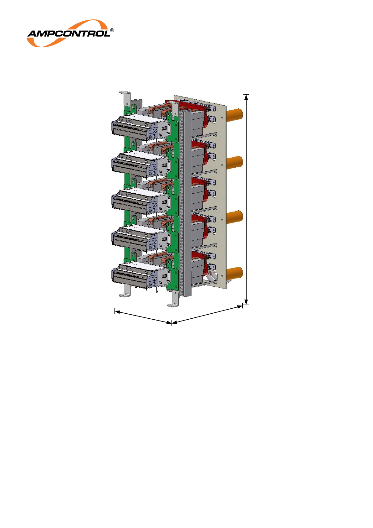
Figure 3.1: Ampcontrol Outlet Cassette System (OCS) .......................................................................... 11
Figure 3.2: Ampcontrol Fixed Cassette System (FCS) ............................................................................ 12
Figure 4.1: 2-Way OCS Dimensions (Pictured with 2 Cassettes Installed) .............................................. 16
Figure 4.2: 3-Way OCS Dimensions (Pictured with 3 Cassettes Installed) .............................................. 16
Figure 4.3: FCS Dimensions (Pictured with 5 Cassettes Installed) ......................................................... 17
Figure 4.4: Remote Termination Unit (RTX) ........................................................................................... 18
Figure 6.1: Actuator position within chassis ............................................................................................ 29
TABLE OF TABLES
Table 1: Definitions ................................................................................................................................... 7
Table 2: Event Log Entry Types ............................................................................................................. 23
Table 3: Outlet Parameter Descriptions .................................................................................................. 26
Table 4: Load Parameter Descriptions ................................................................................................... 27
Table 5: Protection Element - Earth Leakage Trip Characteristics .......................................................... 30
Table 6: Protection Element - Earth Leakage CT Failure Trip Characteristics ........................................ 31
Table 7: Protection Element – Residual Voltage Trip Characteristics ..................................................... 31
Table 8 Protection Element - Earth Continuity Series Trip Characteristics .............................................. 33
Table 9: Protection Element - Earth Continuity Shunt Trip Characteristics .............................................. 33
Table 10: Protection Element - Earth Continuity Pilot Interlock Trip Characteristics ................................ 34
Table 11: Protection Element - Earth Fault Lockout (EFLO) Trip Characteristics .................................... 35
Table 12: Protection Element – High Voltage Insulation Test Characteristics ......................................... 35
Table 13: Protection Element – Voltage Detection (Loss of Vacuum) Trip Characteristics ...................... 36
Table 14: Protection Element – Frozen Contactor Trip Characteristics ................................................... 37
Table 15: Protection Element – Contactor Close Fail Trip Characteristics .............................................. 37
Table 16: Protection Element – External Open Trip Characteristics ........................................................ 38
Table 17: Protection Element – Coil Voltage Detection Trip Characteristics ........................................... 38
Table 18: Protection Element – Over Current Trip Characteristics .......................................................... 39
Table 19: Protection Element – Motor Overload Trip Characteristics ...................................................... 41
Table 20: Protection Element – Short Circuit Trip Characteristics ........................................................... 44
Table 21: Protection Element – Current Balance Trip Characteristics ..................................................... 45
Table 22: Protection Element – Under Current Trip Characteristics ........................................................ 46
Table 23: Protection Element – Under Voltage Trip Characteristics ........................................................ 46
Page 7

Ampcontrol Pty Ltd – ABN 28 000 915 542
OCS USER MANUAL
MAG-182 Version 6 – September/2020
Uncontrolled Copy - Refer to Ampcontrol Website for Latest Version
Page 7 of 72
APPROVED FOR EXTERNAL DISTRIBUTION
– PROPERTY OF AMPCONTROL PTY LTD
– NOT TO BE REPRODUCED IN PART
DEFINITIONS
Table 1: Definitions
Term
Definition
Cassette
A Cassette is the unit that is installed within Outlet Cassette System (OCS)
or Fixed Cassette System (FCS). There are two types: FCS Cassettes and
OCS Cassettes.
Each Cassette houses a Protection Element, phase current transformers
and main contactor components.
CB
Circuit Breaker; Main circuit breaker that controls power to all outlets.
CBR
Circuit Breaker Relay; power relay within the Cassette Protection Element
to control the supply to the circuit breaker coil. The Protection Element’s
CBR output is designed for use with under voltage tripping coils.
FCS
FCS is the acronym for the Ampcontrol Fixed Cassette System.
MC
Main Contactor; the main power circuit opening device. Installed within the
Cassette, the main contactor is opened and closed in order to turn the
outlet on and off.
MCR
Main Contactor Relay; power relay installed within the Cassette Protection
Element to control the supply to the main contactor coil. All trip times
specified are to the opening of the MCR.
OCS
OCS is the acronym for the Ampcontrol Outlet Cassette System
Parameter Dongle
A small memory device which is used to store setting information for the
MEM and RTX modules which is attached to the wiring harness of the
installation.
Protection Element
The Protection Element is installed in each Cassette, providing a host of
protection functions for the outlet.
RTX
Remote Termination Device; Module that is installed at the machine end of
the pilot to provide machine identification and communications.
Page 8

Ampcontrol Pty Ltd – ABN 28 000 915 542
OCS USER MANUAL
MAG-182 Version 6 – September/2020
Uncontrolled Copy - Refer to Ampcontrol Website for Latest Version
Page 8 of 72
APPROVED FOR EXTERNAL DISTRIBUTION
– PROPERTY OF AMPCONTROL PTY LTD
– NOT TO BE REPRODUCED IN PART
1 SAFETY AND OTHER WARNINGS
For safety reasons, the OCS must be installed, operated and serviced only by competent personnel.
Please read and understand this instruction manual completely before installing, operating or servicing
this equipment. Failure to install or operate this instrument in accordance with the instructions contained
in this manual may create hazardous operating conditions.
1.1 Safe Use of Equipment
The equipment supplied has been designed and manufactured to ensure safe operation. The equipment
must only be used within the design parameters.
The instructions within this manual must be observed as an aid towards achieving the safest possible
installation.
Persons responsible for installation, maintenance, or operation, must observe the following
instructions:
1.1.1 Changes to Equipment
Changes in the design and modifications to the equipment are not permitted. Unauthorised changes
made to the hardware or operating firmware will void the manufacturer's warranty, and may
compromise the integrity of the system into which it is installed and other connected equipment.
1.1.2 Equipment Knowledge
Experience with, or understanding of, this equipment is essential for the safe installation and removal of
the equipment. Therefore, please read and understand this manual prior to use. Competency based
training courses are recommended and are available on request.
1.1.3 Manual Handling
Precautions have been taken to ensure all equipment is safe to handle and free from sharp edges.
However care should always be taken when handling enclosures and gloves should be worn.
1.1.4 Installation
Correct operation and safety depend on the OCS and associated equipment being installed correctly.
Mechanical and or electrical installation and maintenance of plant and equipment must only be carried
out by appropriately qualified personnel and must be tested thoroughly prior to operation.
1.1.5 Operation
As safety depends on the OCS functioning correctly it is highly recommended that all safety functions
of the OCS be periodically tested to ensure correct operation.
Page 9

Ampcontrol Pty Ltd – ABN 28 000 915 542
OCS USER MANUAL
MAG-182 Version 6 – September/2020
Uncontrolled Copy - Refer to Ampcontrol Website for Latest Version
Page 9 of 72
APPROVED FOR EXTERNAL DISTRIBUTION
– PROPERTY OF AMPCONTROL PTY LTD
– NOT TO BE REPRODUCED IN PART
1.1.6 Certification
WARNING!
To comply with the Conditions of Certification, ensure full serviceable
life of the product, and avoid nullifying the warranty, it is essential to
exercise great care with the installation, use and storage of the system
components. Failure to comply with the Conditions of Certification may
seriously compromise the integrity of the system and/or its components,
and the consequence could be fatal. The user must ensure that the
"Special Conditions" outlined in the certificate and associated
attachment is met or the certificate (and the I.S. rating) will not be valid.
Refer to the relevant section of the safety file for copies of certificates of conformity outlining the
special conditions of the certification for the explosion protected equipment or components.
The latest certificate and its associated attachments outlining the special conditions of the
certification are maintained and available on the IEC Ex Website: http://iecex.iec.ch.
Page 10
Ampcontrol Pty Ltd – ABN 28 000 915 542
OCS USER MANUAL
MAG-182 Version 6 – September/2020
Uncontrolled Copy - Refer to Ampcontrol Website for Latest Version
Page 10 of 72
APPROVED FOR EXTERNAL DISTRIBUTION
– PROPERTY OF AMPCONTROL PTY LTD
– NOT TO BE REPRODUCED IN PART
2 RECEIVING AND STORAGE
2.1 Receiving
All possible precautions are taken to protect the equipment against damage or losses during shipment,
however before accepting delivery, check all items against the packing list or bill of loading. If there is
evidence of physical damage, notify Ampcontrol immediately.
Notify Ampcontrol immediately in case of any discrepancies to the packing list. Keep a record of any
claims and correspondence. Photographs are recommended.
Where practicable do not remove protective covers prior to installation unless there are indications of
damage. Boxes opened for inspection and inventory should be carefully repacked to ensure protection of
the contents or else the parts should be packaged and stored in a safe place. Examine all packing
boxes, wrappings and covers for items attached to them, retain and store any approval documentation
for your safety file as applicable prior to wrapping being discarded.
2.2 Inspection
Equipment that is found to be damaged or has been modified away from its published specification must
not be used. Please contact Ampcontrol if the equipment is suspected to be different than that ordered or
if it does not match the published specifications.
2.3 Storage after Delivery
When the equipment is not to be installed immediately, proper storage is important to ensure protection
of equipment and validity of warranty.
All equipment should be stored indoors between 0-40˚C, preferably on shelves and protected from
moisture and sunlight.
2.4 Unpacking of Equipment
The method of packing used will depend on the size and quantity of the equipment. The following
cautions should be interpreted as appropriate.
CAUTION!
Take care when unpacking crates as the
contents may have shifted during transport.
ENVIRO
The disposal of packaging materials, replaced parts, or components
must comply with environmental restrictions without polluting the soil,
air or water.
Ensure that any timber and cardboard used as packaging is disposed
of in a safe and environmentally responsible manner.
Where possible, dispose of all waste products i.e. oils, metals, plastic
and rubber products by using an approved recycling service centre.
Page 11
Ampcontrol Pty Ltd – ABN 28 000 915 542
OCS USER MANUAL
MAG-182 Version 6 – September/2020
Uncontrolled Copy - Refer to Ampcontrol Website for Latest Version
Page 11 of 72
APPROVED FOR EXTERNAL DISTRIBUTION
– PROPERTY OF AMPCONTROL PTY LTD
– NOT TO BE REPRODUCED IN PART
3 PRODUCT OVERVIEW
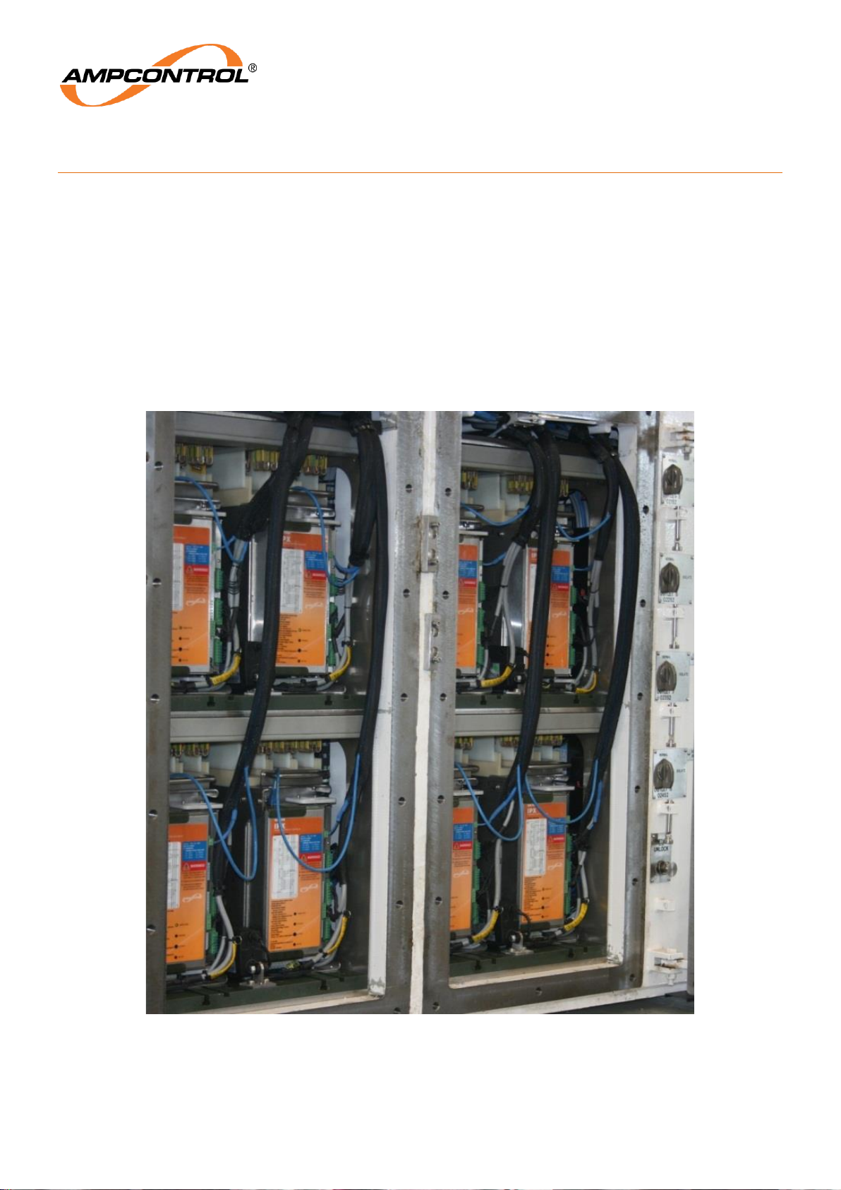
The Ampcontrol Outlet Cassette System (OCS) is a major advancement in control and protection
technology. The OCS combines the outlet contactor, protection element, current transformers and outlet
test circuitry into a single replaceable unit. This has the advantage of resulting in minimal down-time in
the event of a fault.
The Ampcontrol OCS is available in two types: the standard OCS and the Fixed Cassette System (FCS).
The OCS provides isolation and earthing of individual outlets via integrated actuators that are controlled
at the touch of a button via a Human Machine Interface (HMI) screen. In this manner, operators are not
exposed to potential electric shocks resulting from residual static charge on the cable. This also
eliminates a potential ignition source of an explosive atmosphere.
Figure 3.1: Ampcontrol Outlet Cassette System (OCS)
Page 12
Ampcontrol Pty Ltd – ABN 28 000 915 542
OCS USER MANUAL
MAG-182 Version 6 – September/2020
Uncontrolled Copy - Refer to Ampcontrol Website for Latest Version
Page 12 of 72
APPROVED FOR EXTERNAL DISTRIBUTION
– PROPERTY OF AMPCONTROL PTY LTD
– NOT TO BE REPRODUCED IN PART
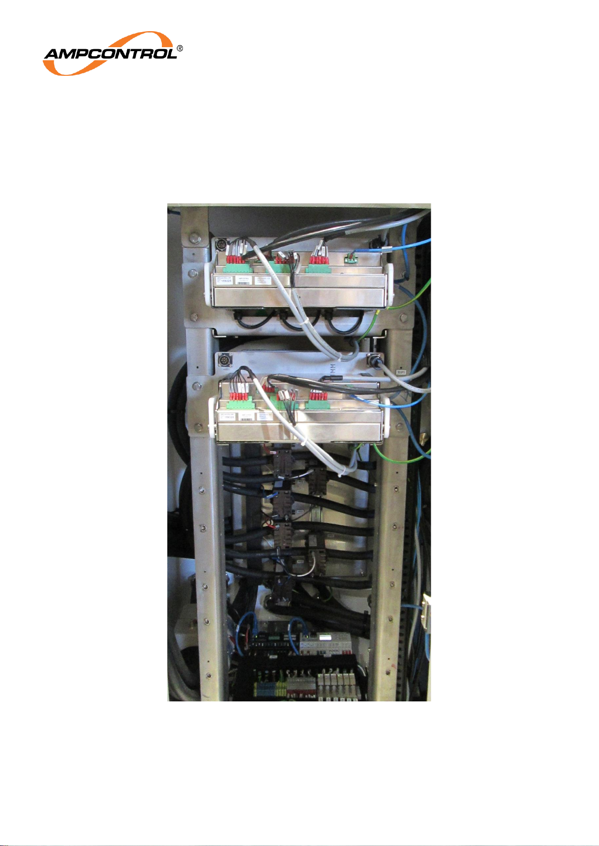
The FCS (1.1kV systems only) sacrifices the remote isolation and earthing functionality of the OCS to
provide a higher outlet density. Due to the compact nature of the FCS, 10 outlets are able to be installed
in the same area used by a conventional 8 outlet system. The FCS is designed as a fully bolted, nonwithdrawable installation, whilst still minimising downtime by providing fast and easy removal of the
cassette protection components.
Figure 3.2: Ampcontrol Fixed Cassette System (FCS)
Page 13

Ampcontrol Pty Ltd – ABN 28 000 915 542
OCS USER MANUAL
MAG-182 Version 6 – September/2020
Uncontrolled Copy - Refer to Ampcontrol Website for Latest Version
Page 13 of 72
APPROVED FOR EXTERNAL DISTRIBUTION
– PROPERTY OF AMPCONTROL PTY LTD
– NOT TO BE REPRODUCED IN PART
Key Features:
Individual outlet isolation and earthing system (OCS)
Operations via HMI interface
Ethernet communications
Cassette Protection Element
All electrical protection functions are provided by the new generation OCS Protection Element and
include:
Earth Leakage
Earth Fault Lockout
Earth Continuity (including remote start mode)
Contactor Failure protection
Motor thermal overload protection
Short circuit protection
Under current protection
Current balance protection
Under voltage protection
Automatic HV insulation test prior to outlet closing
Machine identification.
The following Control and Monitoring functions are accessed via the Ethernet/IP communications:
Monitoring of key parameters for all protection functions
Protection settings and parameter adjustments
Statutory tests
Resetting of protection trips
Outlet control (starting and stopping)
The status of all protection functions and control logic.
All control of outlet(s) is from the HMI screen.
Page 14

Ampcontrol Pty Ltd – ABN 28 000 915 542
OCS USER MANUAL
MAG-182 Version 6 – September/2020
Uncontrolled Copy - Refer to Ampcontrol Website for Latest Version
Page 14 of 72
APPROVED FOR EXTERNAL DISTRIBUTION
– PROPERTY OF AMPCONTROL PTY LTD
– NOT TO BE REPRODUCED IN PART
4 INSTALLATION
4.1 General Warnings
These instructions have been designed to assist users of the OCS with installation.
Before the OCS can be installed, there are a number of things that need to be considered and
understood to prevent incorrect or unsafe operation of the OCS or the system into which it is installed.
Along with relevant competence, and an understanding of the target application, the following points
should be considered:
4.1.1 Ensure that the information provided in this user manual is fully understood.
It is extremely important that the limitations and functionality of the OCS are understood to prevent
incorrect installation and use from creating a potentially dangerous risk. If in doubt as to the nature of
the limitations or their implication, refer to the installation’s safety dossier or consult a competent
authority such as a supervisor or Ampcontrol technical representative.
4.1.2 Ensure that the application into which the OCS is being installed has been properly defined, designed and approved.
Any system intended to mitigate the risk of injury needs to be properly designed and implemented.
Such a system must be the result of structured risk analysis with the outcomes used to define the
system requirements. These requirements, in turn, will guide the choice of instrumentation, logic
solvers and actuators needed to implement the system. Understanding the needs of the system will
ensure proper selection of equipment.
4.1.3 Ensure that the OCS will properly perform the required functions within the system design.
It is important to understand how the OCS is intended to interact with other equipment within a system.
For safe and reliable use, it is crucial that neither the OCS’s logical operation nor its signalling be
compromised by incompatibilities with connected equipment.
4.1.4 Modifications of any form to the OCS are prohibited.
The OCS as supplied has been designed and manufactured to comply with the requirements of
protection standards. If modifications of any form are made to the OCS, the equipment may no longer
be fit for purpose. If any modifications or damage to the OCS is evident, do not use the equipment and
contact Ampcontrol for advice.
Page 15
Ampcontrol Pty Ltd – ABN 28 000 915 542
OCS USER MANUAL
MAG-182 Version 6 – September/2020
Uncontrolled Copy - Refer to Ampcontrol Website for Latest Version
Page 15 of 72
APPROVED FOR EXTERNAL DISTRIBUTION
– PROPERTY OF AMPCONTROL PTY LTD
– NOT TO BE REPRODUCED IN PART
4.2 Mandatory Installation Practices
The following information must be adhered to when installing the OCS. Failure to adhere to this
information may give rise to unsafe operation.
Using the OCS in a manner that exceeds its electrical, functional or physical specifications, or in a way
that is contrary to its operating restrictions, may create risks to personnel and/or equipment resulting in
injury or death.
The OCS is to be installed in an electrical system having a fault level equal to or less than as
marked on the name plate.
The OCS’s control supply must remain within the specified voltage range.
The installation of the OCS must be carried out by suitably trained and qualified personnel.
Identification labels fixed to the OCS must not be damaged, removed or covered.
The installation is to be in accordance with the relevant installation Standards/Codes of Practice.
Modifications must not be made to any part of the OCS. As supplied, the unit is built to, and
complies with the relevant standards. Modifications to its construction will render the unit noncompliant.
Complete and accurate records of the installation must be kept as part of the site installation.
The equipment is to be maintained as per the conditions as listed in the certification
documentation.
NOTE
If the OCS is to be used in a hazardous environment, it must be
installed within suitably certified flameproof enclosure.
NOTE
The equipment is to be operated within an ambient temperature range
of - 20°C to + 40°C.
Page 16
Ampcontrol Pty Ltd – ABN 28 000 915 542
OCS USER MANUAL
MAG-182 Version 6 – September/2020
Uncontrolled Copy - Refer to Ampcontrol Website for Latest Version
Page 16 of 72
APPROVED FOR EXTERNAL DISTRIBUTION
– PROPERTY OF AMPCONTROL PTY LTD
– NOT TO BE REPRODUCED IN PART
4.3 Mechanical Arrangement
4.3.1 OCS Dimensions
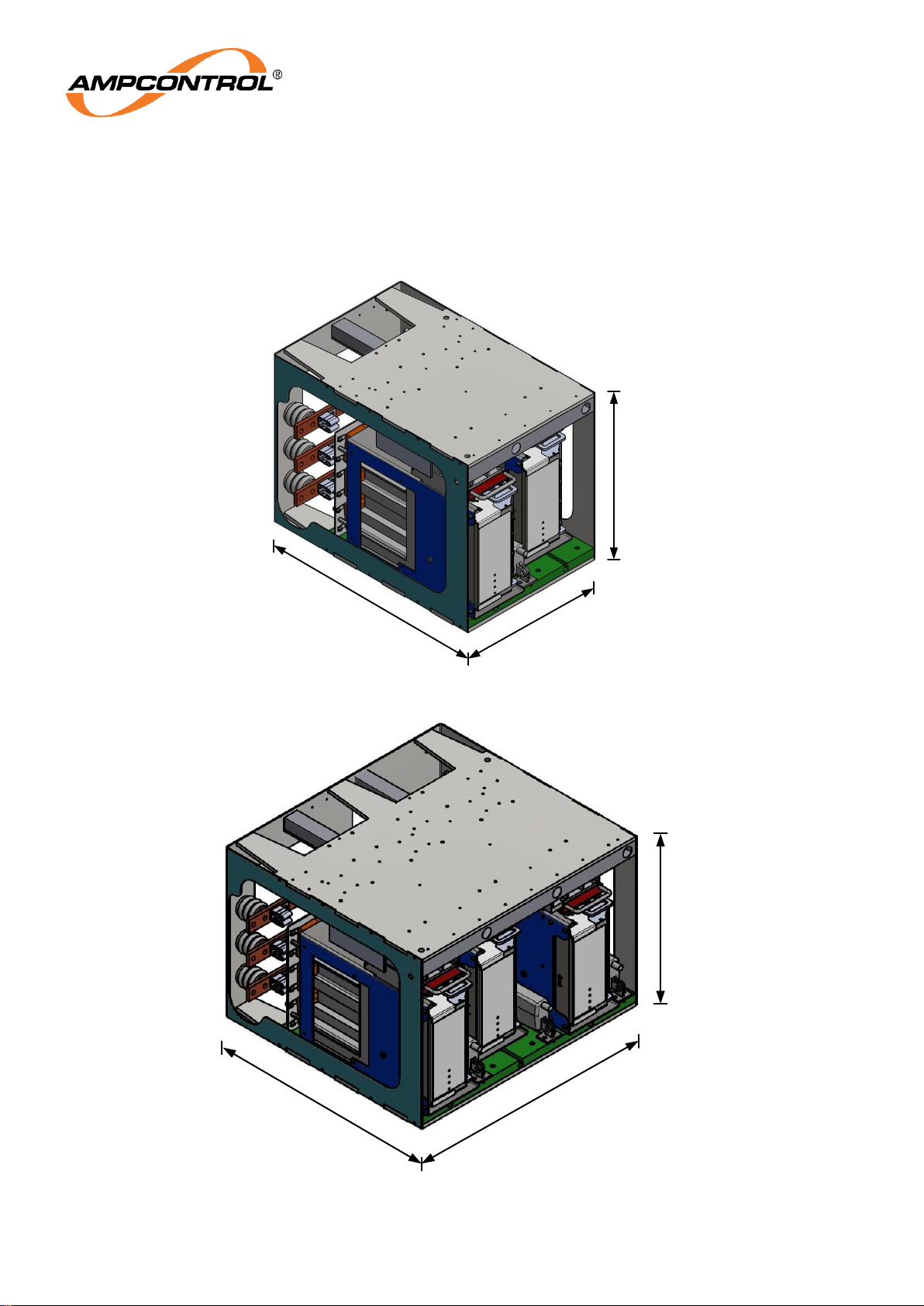
The OCS is available in two sizes: the 2-Way OCS and the 3-Way OCS. These modules are designed
to be stacked on top of each other, allowing the best utilisation of the installation area.
Figure 4.1: 2-Way OCS Dimensions (Pictured with 2 Cassettes Installed)
Figure 4.2: 3-Way OCS Dimensions (Pictured with 3 Cassettes Installed)
683
449
509
683
750
509
Page 17
Ampcontrol Pty Ltd – ABN 28 000 915 542
OCS USER MANUAL
MAG-182 Version 6 – September/2020
Uncontrolled Copy - Refer to Ampcontrol Website for Latest Version
Page 17 of 72
APPROVED FOR EXTERNAL DISTRIBUTION
– PROPERTY OF AMPCONTROL PTY LTD
– NOT TO BE REPRODUCED IN PART
4.3.2 FCS Dimensions
The FCS has a very high outlet density, allowing more outlets to be installed with a smaller footprint.
Figure 4.3: FCS Dimensions (Pictured with 5 Cassettes Installed)
4.4 Electrical Installation Information
Refer to drawing OCSE002in APPENDIX B: DRAWINGS for electrical installation information.
450
665
1160
Page 18
Ampcontrol Pty Ltd – ABN 28 000 915 542
OCS USER MANUAL
MAG-182 Version 6 – September/2020
Uncontrolled Copy - Refer to Ampcontrol Website for Latest Version
Page 18 of 72
APPROVED FOR EXTERNAL DISTRIBUTION
– PROPERTY OF AMPCONTROL PTY LTD
– NOT TO BE REPRODUCED IN PART
4.5 External Accessories
4.5.1 Earth Leakage CT
The Outlet Cassette Protection Element uses an Ampcontrol EL500 series current transformer for earth
leakage measurements. For the purposes of outlet identification tests during operation, the earth
leakage toroid is installed separately to the Cassette.
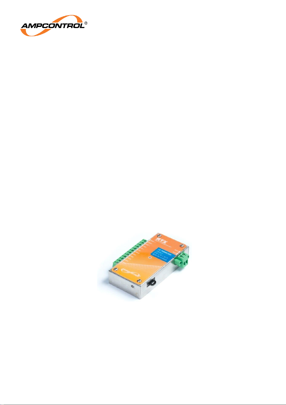
4.5.2 Remote Termination Unit (RTX)
The RTX is a microprocessor based module that can be utilised to replace the diode at the end of the
trailing cable pilot conductor. It is powered by and communicates via the pilot line. Its non-volatile
memory stores the parameters to configure the outlet as appropriate for the connected machine. The
RTX Module is pictured in Figure 4.4.
All terminals are fully shrouded, with the pilot and earth terminals being segregated from the other
terminals.
The RTX provides remote start and stop facilities. The circuitry involved in these functions is selfdiagnostic and will cause the outlet to turn off if the circuits are earthed or interconnected. This reduces
the chance of the outlet operating when not required to do so due to wiring faults. It should be noted
that these functions are operational only, and that any emergency stops should be wired directly into
the pilot circuit.
PTC terminals are provided for a semiconductor ‘switching’ thermistor. These terminals are protected in
a similar manner to the stop and start circuits. If the remote start, stop and PTC functions are not
required, each set of terminals must be bridged in order to start the Protection Element.
Five RTD inputs are provided for PT100 RTDs. These terminals can also be used with resistor
networks to provide digital information back to the Cassette Protection Element.
A parameter dongle allows an RTX to be replaced without needing to re-program the parameters.
When installed, this dongle should be firmly secured to the machine/equipment.
Figure 4.4: Remote Termination Unit (RTX)
4.5.3 Parameter Dongle
Parameters important to the running of the Protection Element and the safe operation of the outlet onto
which it is connected are stored in the Protection Element Parameter Dongle. The Parameter Dongle is
exchangeable between Protection Elements, but it is intended to be physically tethered to the outlet
that it controls.
Although the Protection Element and the RTX use the same hardware parameter dongle the
parameters they store are different. As such the parameter dongle is not interchangeable between the
Protection Element and RTX.
Page 19
Ampcontrol Pty Ltd – ABN 28 000 915 542
OCS USER MANUAL
MAG-182 Version 6 – September/2020
Uncontrolled Copy - Refer to Ampcontrol Website for Latest Version
Page 19 of 72
APPROVED FOR EXTERNAL DISTRIBUTION
– PROPERTY OF AMPCONTROL PTY LTD
– NOT TO BE REPRODUCED IN PART
5 COMMISSIONING AND CALIBRATION
Prior to being put into service, the electrical protection system must be correctly commissioned. This
manual does not cover system commissioning; the full scope of commissioning tests should be
determined during the risk assessment or FMEA covering the design of the electrical protection system.
The following test can provide guidance on checking the correct operation of the Cassette Protection
Element during commissioning. These tests should be performed on each individual Cassette within the
installed OCS.
This is not intended to provide an exhaustive commissioning checklist, but should be considered to be a
minimum set of tests.
5.1 Earth Leakage
Test the correct operation of earth leakage circuits by injecting a fault current through the Earth Leakage
CT. Ensure that all relevant tripping circuits operate successfully and that latched trips may be reset in
the appropriate manner.
Disconnect the toroid from the Cassette Protection Element and ensure that an EL CT fault trip is issued
with similar effect.
5.2 Residual Voltage
This is applicable to the Residual Voltage Protection Element Version only. Test the correct operation of
residual voltage detection circuitry by injecting a residual voltage onto the phases. Ensure that all
relevant tripping circuits operate successfully and that latched trips may be reset in the appropriate
manner.
These tests can be facilitated using residual voltage test relays, built into the Cassette Protection
Element. These relays are controlled using the Cassette Protection Element’s communications interface.
5.3 Earth Fault Lockout
Test the correct operation of Earth Fault Lockout protection by connecting suitably rated test resistors to
the power conductors. Attempt to energise the outlet and confirm that the Cassette Protection Element
trips on Earth Fault Lockout.
WARNING!
If the Earth Fault Lockout does not trip during this test, full system
voltage and power may be subsequently applied to the test
resistors.
5.4 Earth Continuity
Test that the Earth Continuity protection is operational by creating an open circuit on the pilot conductor.
Ensure that all relevant tripping circuits operate successfully and that latched trips may be reset in the
appropriate manner.
Repeat with a short circuit between pilot and earth.
These tests can be facilitated using earth continuity test relays, built into the Cassette Protection
Element. These relays are controlled using the Cassette Protection Element’s communications interface.
5.5 Insulation Test (High Voltage)
If the Earth Fault Lockout and Earth Continuity tests are successful, check that an automatic HV
insulation test is initiated by the Cassette Protection Element when the module is started.
Page 20
Ampcontrol Pty Ltd – ABN 28 000 915 542
OCS USER MANUAL
MAG-182 Version 6 – September/2020
Uncontrolled Copy - Refer to Ampcontrol Website for Latest Version
Page 20 of 72
APPROVED FOR EXTERNAL DISTRIBUTION
– PROPERTY OF AMPCONTROL PTY LTD
– NOT TO BE REPRODUCED IN PART
WARNING!
During this test the Cassette Protection Element will generate up to
2700VDC from the 24 VDC input supply and apply this voltage to the
phase conductors.
5.6 Over Current/Motor Overload Current Injection
Test the Over Current/Motor Overload protection by carrying out secondary/primary injection on the CT
inputs of the Cassette Protection Element.
Inject 2x Full Load Current (FLC) into one of the CT terminals and ensure that all relevant tripping
circuits operate successfully, in the time expected according to the settings employed, and that latched
trips may be reset in the appropriate manner. Repeat on the other CT terminals.
5.7 Short Circuit Current Injection
Test the Short Circuit protection by carrying out secondary/primary injection on the CT inputs of the
Cassette Protection Element.
Inject a current value relevant to the settings employed into one of the CT terminals and ensure that all
relevant tripping circuits operate successfully, in the time expected, and that latched trips may be reset in
the appropriate manner. Repeat on the other CT terminals.
5.8 Main Contactor Fail
While the Cassette Protection Element is stopped (that is, the MCR output is open), apply a voltage on
the load side of the contactor. The voltage must be greater than the selected trip level. Ensure that a
CBR trip is initiated by the Cassette Protection Element.
NOTE
A Main Contactor Fail (MCF) trip can be reset by pressing the MCF
Reset Pushbutton on the front of the OCS Protection Element or
through the communications protocol.
While the Cassette Protection Element is stopped, close the MCI digital input. Ensure that a CBR trip is
initiated by the Cassette Protection Element.
5.9 Voltage Measurement
Validate the voltage measurement function of the Cassette Protection Element by checking the
measured voltages via the PLC when the main contactor is closed.
5.10 RTX
Validate the correct operation of the RTX by making changes to load parameters, moving the machine to
a different outlet and ensuring that the correct settings are available on the new outlet.
Page 21

Ampcontrol Pty Ltd – ABN 28 000 915 542
OCS USER MANUAL
MAG-182 Version 6 – September/2020
Uncontrolled Copy - Refer to Ampcontrol Website for Latest Version
Page 21 of 72
APPROVED FOR EXTERNAL DISTRIBUTION
– PROPERTY OF AMPCONTROL PTY LTD
– NOT TO BE REPRODUCED IN PART
6 PRODUCT OPERATION
6.1 Outlet Control
In a typical installation, the outlet contactor is directly controlled by the Protection Element. The
supervising PLC will send commands to the Protection Element to start or stop the outlet. The Protection
Element will respond by controlling its MCR output accordingly. In the event of any trip condition
occurring, the Protection Element will open the MCR output (or CBR output as appropriate) and prevent
reclosing the output until the fault condition has cleared and the trip has been reset.
To close an outlet controlled by a Protection Element, the supervising PLC will send a start command.
The following start sequence will be followed:
If there are any active trips, the Protection Element will ignore any start command received.
If all trips are cleared, the Protection Element will initiate a start sequence.
An earth fault lockout test is conducted. This test checks for a cable fault to earth. The test
voltage and current are limited to intrinsically safe levels. If the test fails, the start sequence will
be cancelled and the Protection Element will report an earth fault lockout trip.
If the earth fault lockout test passes, the Protection Element may then conduct an optional high
voltage DC insulation test on the cable. If the insulation test fails, the start sequence will be
cancelled and the Protection Element will report an insulation test trip. The insulation test can
also be disabled via parameter settings.
If the insulation test passes, the start sequence moves to the closing state and the MCR output
will be closed.
The Protection Element now waits for the MCI digital input to close. This auxiliary feedback from
the signal confirms that the main contactor has closed. If the MCI does not follow the MCR within
five seconds a ‘close fail’ trip will occur and the start sequence will be cancelled.
If the MCI digital input closes, the Protection Element moves from the start sequence to the
running state. It will continue in the running state with the outlet closed until a stop command is
received or any protection function trips.
If at any point during the start sequence a stop command is received or a protection function trips
the start sequence is immediately cancelled and the MCR (or CBR if appropriate) output will be
opened.
6.2 Control of Resets
All trip resets in the Protection Element are handled by positive edge reset signal events. In this way,
continually driven reset signals will not reset faults. Most trips are reset with a general reset. Some trips
have a dedicated reset, to allow selective control of the reset functions and to provide a level of authority
associated with resetting faults. The trips that require additional reset commands include the Earth
Leakage, Thermal Memory for motor overload protection, Short Circuit and MCF Reset.
Main Contactor Failure events generate a trip that can be reset by the PLC. These trips require an
inspection of the switching equipment associated with the outlet controlling Protection Element and as
such a reset push-button is accessible from the front of the Protection Element and can be operated with
power off.
Page 22

Ampcontrol Pty Ltd – ABN 28 000 915 542
OCS USER MANUAL
MAG-182 Version 6 – September/2020
Uncontrolled Copy - Refer to Ampcontrol Website for Latest Version
Page 22 of 72
APPROVED FOR EXTERNAL DISTRIBUTION
– PROPERTY OF AMPCONTROL PTY LTD
– NOT TO BE REPRODUCED IN PART
6.3 Internal Trips
The Protection Element has a number of trip functions that are not directly associated with the protection
of the outlet, but signal that other dangerous faults have been detected.
6.3.1 CCM ID
The Protection Element has an internal detection circuit to identify the CCM module that is assembled
within the Cassette. If the CCM identity fails to match with that which is expected, the Protection
Element will set this trip. There is currently one CCM version which is used for both 1.1kV and 3.3kV
outlets. If this trip occurs the Cassette should be returned for repair.
6.3.2 MCF Battery Trip
The Protection Element has an internal battery. This is used to power the real time clock (used to
timestamp log messages) as well has power the main contactor fail latch. The health of this battery is
monitored and if the battery condition is failing this trip will be set. If this trip occurs the Protection
Element should be returned to have the battery repaired or replaced.
6.3.3 Internal Logic Error
This trip will be set in the event that an internal fault has been detected. If this trip occurs the Cassette
should be returned for repair.
Page 23

Ampcontrol Pty Ltd – ABN 28 000 915 542
OCS USER MANUAL
MAG-182 Version 6 – September/2020
Uncontrolled Copy - Refer to Ampcontrol Website for Latest Version
Page 23 of 72
APPROVED FOR EXTERNAL DISTRIBUTION
– PROPERTY OF AMPCONTROL PTY LTD
– NOT TO BE REPRODUCED IN PART
6.4 Events Log
A real time clock/calendar is included in the Protection Element. This combines with the non-volatile
memory to provide a data-logging feature. This log sequentially records the time, date and details of the
most recent event. A chronological list of the previous 50 events is stored.
The following events are logged:
Table 2: Event Log Entry Types
Event ID
String
Description
0
Unused
Not a valid Message. Should not be seen.
1
Feed On
Logs the Machine Type (Data1) and Machine
Number (Data2) when the main contactor has been
closed while in RTX mode.
2
Insulation Test Record
The results of an automatic HV insulation test.
3
Earth Leakage Trip
Earth leakage current was measured above the
selected trip level.
4
Series Earth Continuity
Trip
The series resistance of the pilot was measured to
be above the selected trip level.
5
Over current\Overload
Trip
The currents exceeded the bounds of the selected
trip characteristic.
6
Short Circuit INST Trip
An Instantaneous Short Circuit trip occurred.
7
Close Failed
After being requested to close, the Main Contactor
has not closed within 5 seconds. (As detected via
the MCI)
8
Main Contactor Relay
Closed
The main contactor relay was closed.
9
Under Current Trip
Phase currents were measured to be below the
selected trip level.
10
General Trip Reset
A Trip was cleared via a General Reset request.
11
Power Down
The system has been powered down correctly.
12
Protection Element
Dongle Parameter Error
There was an error with the Protection Element
parameter dongle.
13
Unexpected Restart
The MEM Processor restarted without a clean power
down (most likely due to the watchdog resetting the
system).
14
Frozen Contactor
The MCI Detects the contactor is closed while the
Main Contactor is requested to be open.
15
Loss of Vacuum
Voltage was detected at the outlet while the Main
Contactor was open.
16
Current Balance Trip
The difference between the measured phase
currents is greater that the selected trip level.
Page 24

Ampcontrol Pty Ltd – ABN 28 000 915 542
OCS USER MANUAL
MAG-182 Version 6 – September/2020
Uncontrolled Copy - Refer to Ampcontrol Website for Latest Version
Page 24 of 72
APPROVED FOR EXTERNAL DISTRIBUTION
– PROPERTY OF AMPCONTROL PTY LTD
– NOT TO BE REPRODUCED IN PART
Event ID
String
Description
17
Thermal Memory Loss
The system was unable to read the Thermal Memory
value from Battery Backed up Ram while booting.
The Motor Overload value will be initialised to 100%.
18
Main Contactor Opened
The main contactor auxiliary contact opened while in
run mode.
19
RTX Parameter Error
There was an error with the RTX parameter dongle.
20
Shunt Earth Continuity
Trip
The resistance of the pilot to earth was less than the
trip level.
21
Thermal Memory Reset
The thermal memory was overridden by user
intervention & reset to zero.
22
RTX Stop
The RTX stop input was activated causing an outlet
stop.
23
RTX Offline
The RTX went offline causing an outlet trip.
24
Insulation Trip
The pre-start high voltage insulation test failed.
25
RTX Comms Timeout
RTX is online, but there was repeated data
corruption.
26
Power Up
The system has powered up after a clean power
down.
27
Under Voltage Trip
The phase voltage dropped below the trip level
causing the outlet to drop out of run mode.
28
Stopped
General log denoting when the system completed
the request to drop out of run mode.
29
No Coil Voltage Trip
Logs when a ‘No Coil Supply’ trip occurred.
30
CT Detection Error
The earth leakage system could not detect an
adequate toroid connection.
31
Remote Start Stuck
The remote start button was detected to be closed
for longer that the trip limit.
32
PLC Comms Timeout
The PLC failed to provide ‘heart beat’.
33
Start Disabled
The Protection Element was disabled by the PLC
34
Earth Fault Lockout
Trip
The resistance measured between the phases and
earth during an intrinsically safe EFLO test was
below the set level.
35
Unknown Restart
Status
The system has powered up, but cannot work out if
the system powered down cleanly or if it had a
restart.
36
Short Circuit Trip Reset
A short circuit trip was reset.
Page 25

Ampcontrol Pty Ltd – ABN 28 000 915 542
OCS USER MANUAL
MAG-182 Version 6 – September/2020
Uncontrolled Copy - Refer to Ampcontrol Website for Latest Version
Page 25 of 72
APPROVED FOR EXTERNAL DISTRIBUTION
– PROPERTY OF AMPCONTROL PTY LTD
– NOT TO BE REPRODUCED IN PART
Event ID
String
Description
37
Earth Leakage Trip
Reset
An earth leakage trip was reset.
38
Fatal Clock Error
The clock time was not able to be read from the Real
Time Chip.
39
MCF Battery Under
Voltage
The Battery which stores the Main Contactor Failure
state and powers the Battery Backed Ram is under
Voltage (e.g. the battery has reached the end of its
life)
40
Control Mask Changed
Notes that the value of the control mask has been
changed (e.g. a Test Relay has been closed). Data1
stores the old mask value; Data2 stores the new
mask value.
41
Invalid CCM
Logs the fact an invalid CCM was attached to the
Protection Element. This is the logged version of a
‘CCM ID’ trip.
42
Internal Logic Error
An Error has occurred in the operation of the code
within the Protection Element. The log is used to
denote that the stack has grown too big or that the
system has run out of RAM. In normal operation
neither of these things should occur.
43
PTC Trip
The outlet was stopped due to the RTX’s PTC input
exceeding its trip resistance level.
44
RTX RTD Group 1 Trip
The outlet was stopped due to one of the RTD inputs
within group 1 going above the set trip level.
45
RTX RTD Group 2 Trip
The outlet was stopped due to one of the RTD inputs
within group 2 going above the set trip level.
46
Short Circuit LT Trip
Short Circuit ‘Long Time’ tripped.
47
Residual Voltage Trip
Residual voltage was measured above the selected
trip level.
48
Residual Voltage Reset
A residual voltage trip was reset.
49
Pilot Interlock Trip
The Fast element of the earth continuity detected
resistance in excess of 100 Ohms for the selected
trip time.
128 - 218
Parameter Modified.
To work out which parameter was modified, minus
128 from the Event ID (eg 130 means parameter 2
was modified) Outlet parameters are numbered 029, Dongle Load parameters are numbered 30-59
and RTX Load parameters are numbered 60-89. The
value which was changed from is stored in Data1
and the new value is in Data2.
Page 26
Ampcontrol Pty Ltd – ABN 28 000 915 542
OCS USER MANUAL
MAG-182 Version 6 – September/2020
Uncontrolled Copy - Refer to Ampcontrol Website for Latest Version
Page 26 of 72
APPROVED FOR EXTERNAL DISTRIBUTION
– PROPERTY OF AMPCONTROL PTY LTD
– NOT TO BE REPRODUCED IN PART
6.5 Protection Element Parameters
There are two distinct groups of parameters:
6.5.1 Outlet Parameters
Outlet Parameters relate to the particular outlet/Protection Element. Examples include the pilot mode,
outlet number and network settings. These are always stored in the Parameter Dongle.
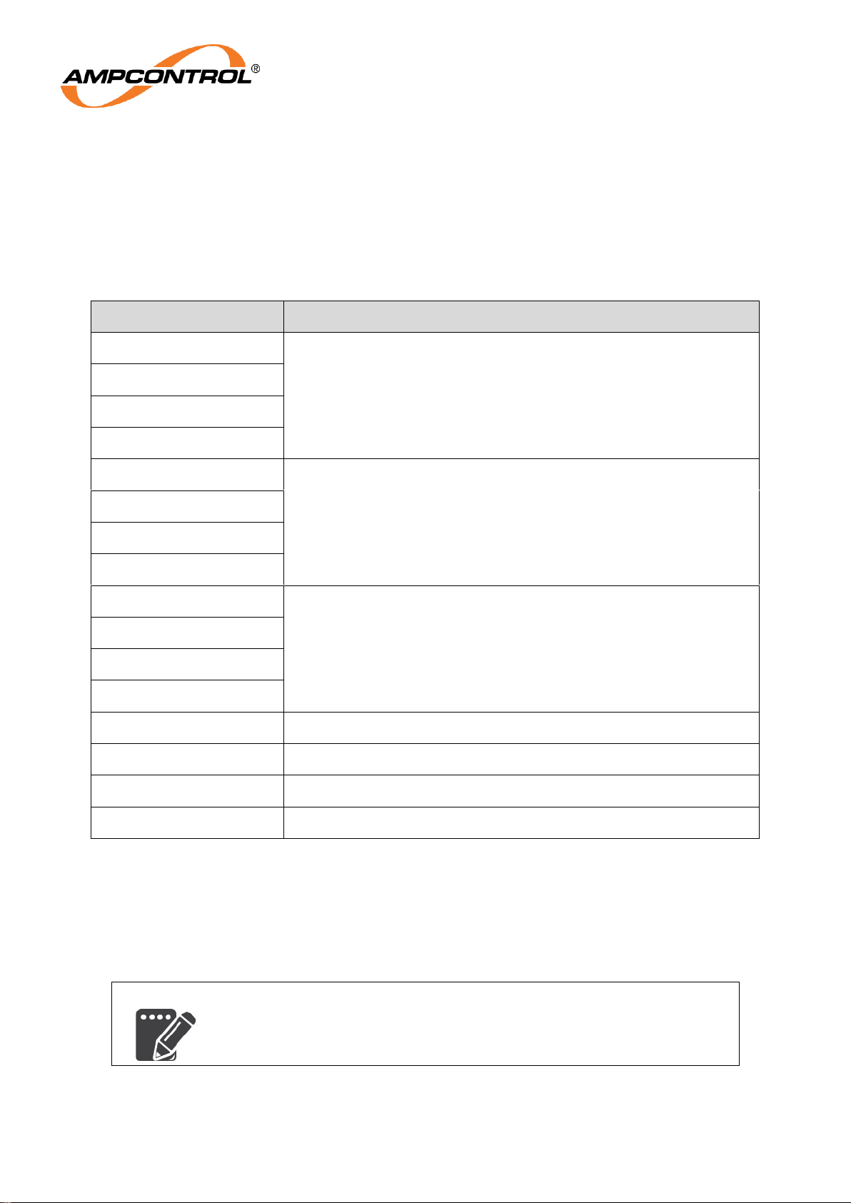
Table 3: Outlet Parameter Descriptions
Name
Description
IP Address Byte 1
IP address for Ethernet communications with the PLC.
IP Address Byte 2
IP Address Byte 3
IP Address Byte 4
Subnet mask Byte 1
Subnet mask for Ethernet communications with the PLC.
Subnet mask Byte 2
Subnet mask Byte 3
Subnet mask Byte 4
Gateway Address Byte 1
Gateway address for Ethernet communications with the PLC.
Gateway Address Byte 2
Gateway Address Byte 3
Gateway Address Byte 4
Pilot mode
Selects the pilot termination method; diode or RTX.
Loss Of Vacuum Level
Trip level for loss of vacuum protection.
Voltage Level
Defines the system voltage level.
SC Output Relay
Selects which output relay the short circuit trips.
6.5.2 Load Parameters
Load Parameters relate to the properties of different loads that may be connected to the Outlet
Cassette. Examples include the motor current, EC trip latch, and remote control. Load parameters can
be stored in the Parameter Dongle of either the RTX (if present) or the Protection Element.
NOTE
Parameters cannot be changed while the Protection Element is running.
Page 27
Ampcontrol Pty Ltd – ABN 28 000 915 542
OCS USER MANUAL
MAG-182 Version 6 – September/2020
Uncontrolled Copy - Refer to Ampcontrol Website for Latest Version
Page 27 of 72
APPROVED FOR EXTERNAL DISTRIBUTION
– PROPERTY OF AMPCONTROL PTY LTD
– NOT TO BE REPRODUCED IN PART
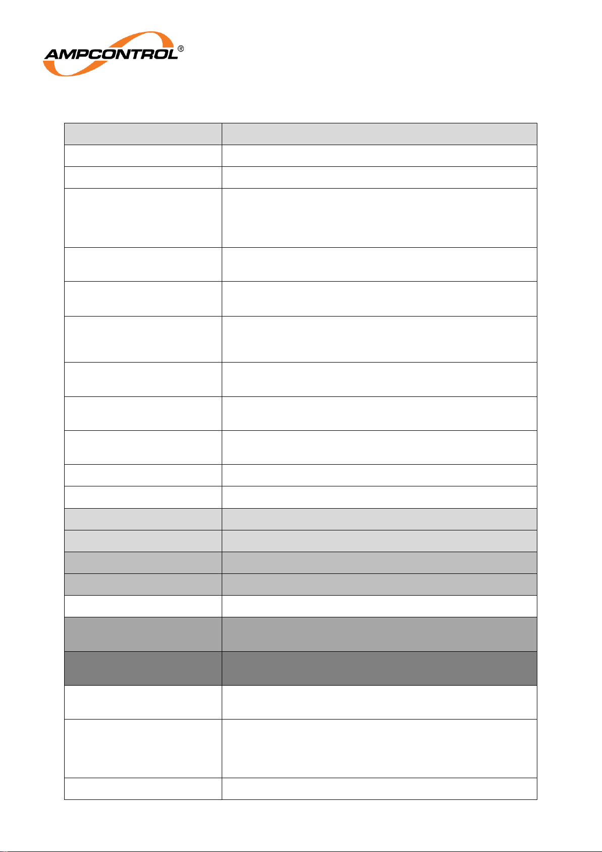
Table 4: Load Parameter Descriptions
Load Parameter Name
Description
Load Machine Type
Text describing the type of machine. (RTX only)
Load Machine ID
Number identifying the machine. (RTX only)
Full Load Current Range
Defines the full load current the Protection Element expects to
see. This determines the scaling of current readings, the base
current for motor overload or inverse time over current protection
and the trip levels for short circuit protection.
Short Circuit Trip Level
Defines the short circuit trip level as a multiple of the full load
current setting.
Short Circuit Trip Time
Determines how long the current reading needs to be above the
trip level before the Protection Element trips.
Over Current Curve
Selects if the over current protection will use one of the inverse
current-time curves or thermal motor protection curve. This
selection also impacts the short circuit functionality.
Over Current Time Multiplier
(TMS)
Determines the trip time characteristic for Over Current/Motor
Overload.
Over Load Cooling Multiplier
Defines the cooling output of the thermal model, when thermal
motor protection is selected.
Over Load Start Block Level
The thermal accumulator must be below this value to allow an
outlet start.
Current Balance Trip Level
Selects the trip level for or disables current balance protection
Under Current Trip Level
Selects the trip level for or disables under current protection
Earth Leakage Trip Level*
Selects the trip level for earth leakage protection
Earth Leakage Trip Time*
Selects the maximum trip time for earth leakage protection
Residual Voltage Trip Level**
Selects the trip level for residual voltage protection
Residual Voltage Trip Time**
Selects the maximum trip time for residual voltage protection
Earth Continuity Trip Level
Selects the nominal series earth continuity trip level
Earth Continuity Trip Time***
Selects the maximum trip time for both series and shunt earth
continuity protection
Pilot Interlock Trip Time****
Selects the maximum trip time for shunt and open circuit earth
continuity protection
Earth Continuity Latch
Selects whether earth continuity trips are latch (requiring general
reset) or automatically reset when healthy
Remote Start
Enables remote start of the outlet via the pilot signal. When the
pilot is set to diode mode, the remote start function uses a 100Ω
series start resistor. When remote start is enabled, the PLC will
not be able to initiate a start.
Insulation Test Trip Level
Selects the trip level for or disables the automatic insulation test.
Page 28
Ampcontrol Pty Ltd – ABN 28 000 915 542
OCS USER MANUAL
MAG-182 Version 6 – September/2020
Uncontrolled Copy - Refer to Ampcontrol Website for Latest Version
Page 28 of 72
APPROVED FOR EXTERNAL DISTRIBUTION
– PROPERTY OF AMPCONTROL PTY LTD
– NOT TO BE REPRODUCED IN PART
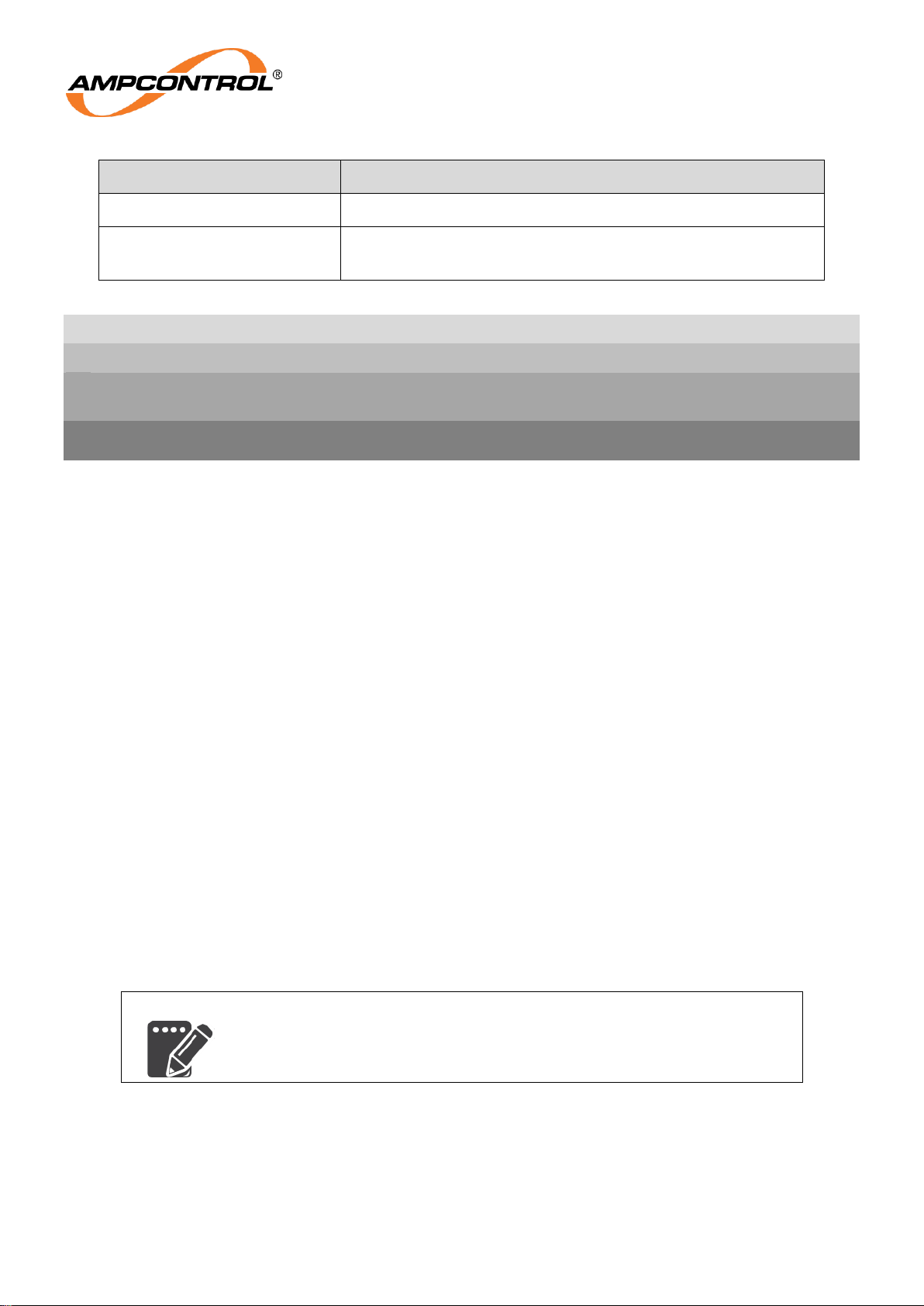
Load Parameter Name
Description
Under Voltage Trip Level
Selects the trip level for or disables under voltage protection
Back EMF Time
Selects the back EMF timer period which inhibits loss of
vacuum detection after the outlet is opened.
’*’ - Setting is not available in the Residual Voltage Protection Element version.
’**’ - Setting is only available in the Residual Voltage Protection Element version.
*** - This setting is only used for series EC protection in the Residual Voltage Protection Element
version.
****’ - Setting is only available in the Residual Voltage Protection Element version. Controls the Shunt
Trip Time and the Open Circuit (>100Ω) Trip Time.
6.6 Time and Date
The time and date are used only to time stamp the events in the log (which are recorded sequentially
regardless of the time and date). The time and date are not used for any control functions.
6.7 Cassette Isolation & Earthing (OCS Only)
Through the use of remotely controlled actuators, the OCS allows individual Outlet Cassettes to be
moved between the service and earth positions. This provides both a break between the outlet phase
conductors and the incoming supply, as well as visual earthing of the outlet cable without the
requirement of a separate earthing outlet.
Each Cassette houses the line and load contacts, vacuum contactor, three current transformers, Earth
Leakage CT and the Protection Element. The cassette is driven between the service and earth positions
by an electrically driven actuator. When in the service position the cassette is connected to the line and
load contacts with the on-board vacuum contactor switching the outlet. In the earthed position the
cassette is disconnected from the line bus and connects the load connections to earth. These earth
contacts are visible through viewing windows.
When in the earth position the supply to the actuator can be externally isolated to prevent operation to
move the cassette away from the earth position.
6.7.1 Actuator
Actuators are used to transition the cassettes between the service and earth positions. The actuator is
controlled via PLC outputs and provides ‘actuator healthy’ feedback to the PLC. An analogue input
corresponding with the position of the actuator rod is compared with the state of the limit switches by
the PLC to indicate the position of the cassette.
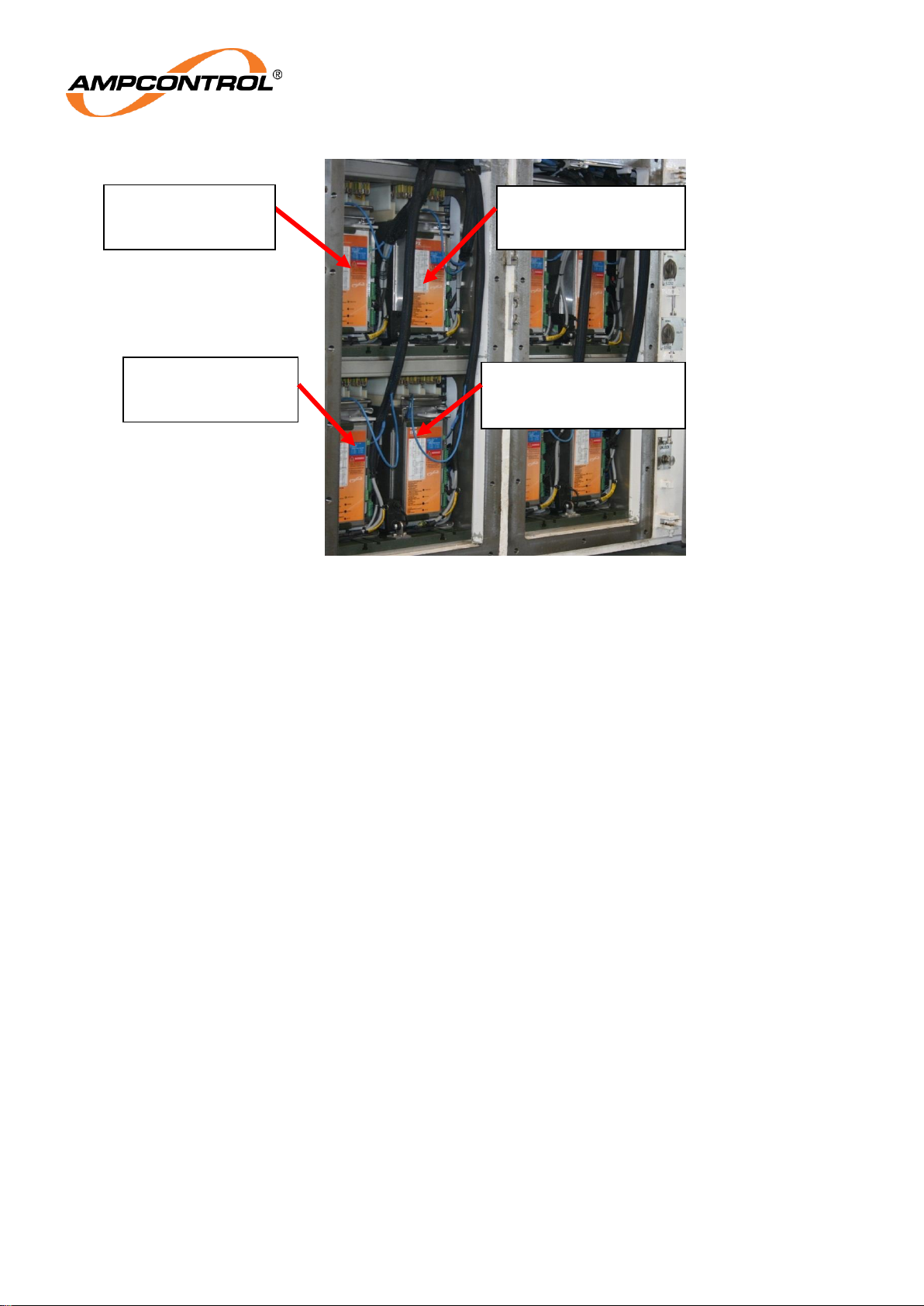
NOTE
Each actuator has a coloured band on each end of the cable to
denote actuator position within the chassis (as shown in Figure 6.1).
Non matching colours will prevent operation of the actuator.
Page 29
Ampcontrol Pty Ltd – ABN 28 000 915 542
OCS USER MANUAL
MAG-182 Version 6 – September/2020
Uncontrolled Copy - Refer to Ampcontrol Website for Latest Version
Page 29 of 72
APPROVED FOR EXTERNAL DISTRIBUTION
– PROPERTY OF AMPCONTROL PTY LTD
– NOT TO BE REPRODUCED IN PART
Figure 6.1: Actuator position within chassis
Position 2
White (p/no 164892)
Position 3
Blue (p/no 164893)
Position 1
Red (p/no 164891)
Position 4
No Band (p/no 164894)
Page 30
Ampcontrol Pty Ltd – ABN 28 000 915 542
OCS USER MANUAL
MAG-182 Version 6 – September/2020
Uncontrolled Copy - Refer to Ampcontrol Website for Latest Version
Page 30 of 72
APPROVED FOR EXTERNAL DISTRIBUTION
– PROPERTY OF AMPCONTROL PTY LTD
– NOT TO BE REPRODUCED IN PART
7 AS/NZS 2081:2011 PROTECTION FUNCTIONS
The Protection Element, housed within the Cassette, provides a number of protection functions that meet
the requirements of the AS/NZS 2081:2011 standard. This protection functions are:
Earth Leakage*
Earth Continuity
Earth Fault Lockout
Main Contactor Fail
* - Not Available on Residual Voltage OCS Protection Element
7.1 Earth Leakage
7.1.1 Trip Characteristics
Table 5: Protection Element - Earth Leakage Trip Characteristics
Parameter
Action
Power Cycle
Trip status maintained
Reset
Requires an earth leakage reset after the trip condition has cleared
Trip Actions
Open Main Contactor
Prevent Main Contactor from closing
Active Period
Always active
Logging
Always logged
Parameters
Trip Level
Trip Time
Monitoring
Earth Leakage current displayed as 0-150% of selected trip level
7.1.2 Operation Summary
The earth leakage protection function uses an Ampcontrol EL500 series toroid to measure the earth
fault current. This function is tested to AS/NZS 2081:2011. A definite time operating characteristic is
provided with adjustable trip sensitivity and an adjustable time delay.
NOTE
Due to size restrictions and the coupling issues related with elongated
current transformers, the Ampcontrol EL500 series earth leakage toroid
is not integral to the Cassette and must be purchased separately.
When a fault occurs such that the trip level and time delays are exceeded, a trip occurs. The trip acts in
the Main Contactor Relay (MCR) logic and is latched. An earth leakage trip is considered a special fault
and requires a specific reset function to be cleared.
The earth leakage current (EL) is displayed as a % of the trip level. When the leakage reaches 100%
for the selected time delay a trip occurs.
Page 31
Ampcontrol Pty Ltd – ABN 28 000 915 542
OCS USER MANUAL
MAG-182 Version 6 – September/2020
Uncontrolled Copy - Refer to Ampcontrol Website for Latest Version
Page 31 of 72
APPROVED FOR EXTERNAL DISTRIBUTION
– PROPERTY OF AMPCONTROL PTY LTD
– NOT TO BE REPRODUCED IN PART
7.1.3 Earth Leakage CT Failure Protection
Table 6: Protection Element - Earth Leakage CT Failure Trip Characteristics
Parameter
Action
Power Cycle
Trip status maintained
Reset
Requires a general reset after the trip condition has cleared
Trip Actions
Open Main Contactor
Prevent Main Contactor from closing
Active Period
Always active
Logging
Always logged
Parameters
None (Trip time and level is fixed)
Monitoring
CT Detect trip status bit
The Protection Element generates a CT Detection Signal to test the integrity of earth leakage circuit.
The CT Detection signal continually tests the earth leakage current transformer, the wiring loop to the
transformer and the input to the protection relay as required by AS/NZS 2081: 2011.
The signal is fed from Pin 6 of the Protection Element. Pass one loop through the earth leakage current
transformer then back to Pin 7.
The Earth Leakage CT Failure trip time is fixed at 4.5 seconds.
NOTE
The loop resistance of the CT Detection Signal circuit must remain
below 1Ω.
7.2 Residual Voltage
7.2.1 Trip Characteristics
Table 7: Protection Element – Residual Voltage Trip Characteristics
Parameter
Action
Power Cycle
Trip status maintained
Reset
Requires a residual voltage reset after the trip condition has cleared
Trip Actions
Open Main Contactor
Prevent Main Contactor from closing
Active Period
Always active
Logging
Always logged
Parameters
Trip Level
Trip Time
Monitoring
Residual Voltage displayed as voltage
Page 32
Ampcontrol Pty Ltd – ABN 28 000 915 542
OCS USER MANUAL
MAG-182 Version 6 – September/2020
Uncontrolled Copy - Refer to Ampcontrol Website for Latest Version
Page 32 of 72
APPROVED FOR EXTERNAL DISTRIBUTION
– PROPERTY OF AMPCONTROL PTY LTD
– NOT TO BE REPRODUCED IN PART
7.2.2 Operation Summary
The residual voltage protection element is a designated unit for use on installations utilising a high
impedance NER. A definite time operating characteristic is provided with adjustable trip sensitivity and
an adjustable time delay.
When a fault occurs such that the trip level and time delays are exceeded, a trip occurs. The trip acts in
the Main Contactor Relay (MCR) logic and is latched. A residual voltage trip is considered a special
fault and requires a specific reset function to be cleared.
The residual voltage (RV) is displayed as the voltage detected. When the leakage reaches the relative
trip level for the selected time delay a trip occurs.
The Label of the Residual Voltage Protection Element has been modified to easily distinguish the two
types apart. The Residual Voltage Protection Element label has been coloured yellow, as opposed to
the Standard Protection Element’s orange label. The two protection elements are not mechanically
keyed, which means the relays can be interchanged, however the protection element will remain in a
tripped state and prevent the outlet from being energised. The Residual Voltage Protection Element
does not require the EL CT to be connected and disables the EL CT detection trip.
NOTE
The Residual Voltage Protection Element and the Standard Protection
Element can be interchanged, however the outlet will not be able to
energise.
7.3 Earth Continuity
The earth continuity function tests for the continuity of the earth between the outlet and the machine, via
the pilot in the trailing cable. This is in accordance with AS/NZS 2081: 2011. The pilot is also used to
transfer data when a remote termination unit (RTX) is used to achieve machine communication.
The Protection Element can be configured to operate in either diode or RTX mode. This determines what
terminating device the relay is expecting on the pilot.
NOTE
The RTX will only be recognised by an OCS Protection Element and will
not be seen as a diode by other earth continuity devices.
CAUTION!
Cable parameters are important to the correct operation of the Pilot
E/C function. Resistance & capacitance values can determine the
length of cable that the relay can drive.
The relay measures the resistance of the pilot - earth loop and the leakage between the pilot and earth
conductors. These measurements are known as the series earth continuity resistance and the shunt
earth continuity resistance, respectively. The shunt measurement ensures that a pilot to earth fault is
detected. If the pilot - earth loop is not healthy (series resistance greater or shunt resistance lower than
their respective trip settings) a trip occurs which in turn opens the MCR to interrupt the main contactor
control circuit.
The trip can be configured as latching or non-latching. This allows the user to determine if the trip is
manually or automatically reset once the pilot - earth loop is healthy.
Page 33
Ampcontrol Pty Ltd – ABN 28 000 915 542
OCS USER MANUAL
MAG-182 Version 6 – September/2020
Uncontrolled Copy - Refer to Ampcontrol Website for Latest Version
Page 33 of 72
APPROVED FOR EXTERNAL DISTRIBUTION
– PROPERTY OF AMPCONTROL PTY LTD
– NOT TO BE REPRODUCED IN PART
The trip settings alter slightly for the Residual Voltage Protection Element version. In this version, the
existing trip time and level (although extended in available values) settings are utilised for the series
earth continuity resistance only. The shunt trip time setting becomes the Pilot Interlock Trip Time Setting.
The Pilot Interlock Trip Time setting is also used for open circuit trip conditions (>100Ω). This means that
the EC settings that have a set trip point (shunt and open circuit faults) can have a separate trip time that
is significantly faster than the series EC setting, which is more commonly used for touch potential
protection.
7.3.1 Pilot Series
Table 8 Protection Element - Earth Continuity Series Trip Characteristics
Parameter
Action
Power Cycle
Trip status maintained
Reset
Requires a general reset after the trip condition has cleared.
Alternatively the trip can be automatically reset depending on the
status of the EC Latch parameter.
Trip Actions
Open Main Contactor Relay
Prevent Main Contactor from closing
Active Period
Always active
Logging
Logged only if outlet is running
Parameters
Trip time
Trip level
Trip latch enable
Monitoring
Available as the raw ohms measurement, resolution of 1Ω.
7.3.2 Pilot Shunt
Table 9: Protection Element - Earth Continuity Shunt Trip Characteristics
Parameter
Action
Power Cycle
Trip status maintained
Reset
Requires a general reset after the trip condition has cleared.
Alternatively the trip can be automatically reset depending on the
status of the EC Latch parameter.
Trip Actions
Open Main Contactor Relay
Prevent Main Contactor from closing
Active Period
Always active
Logging
Always logged
Parameters
Trip time
Trip latch enable
Monitoring
Available as the raw ohms measurement, resolution of 100Ω.
Page 34
Ampcontrol Pty Ltd – ABN 28 000 915 542
OCS USER MANUAL
MAG-182 Version 6 – September/2020
Uncontrolled Copy - Refer to Ampcontrol Website for Latest Version
Page 34 of 72
APPROVED FOR EXTERNAL DISTRIBUTION
– PROPERTY OF AMPCONTROL PTY LTD
– NOT TO BE REPRODUCED IN PART
7.3.1 Pilot Interlock
Table 10: Protection Element - Earth Continuity Pilot Interlock Trip Characteristics
Parameter
Action
Power Cycle
Trip status maintained
Reset
Requires a general reset after the trip condition has cleared.
Alternatively the trip can be automatically reset depending on the
status of the EC Latch parameter.
Trip Actions
Open Main Contactor Relay
Prevent Main Contactor from closing
Active Period
Always active
Logging
Always logged
Parameters
Trip time
Trip latch enable
Monitoring
Resolution of Series and Shunt measurements is as per 7.3.1 & 7.3.2.
7.3.2 Pilot Remote Start
Remote start mode can be used to allow the start sequence to be initiated from the load via the pilot
signal. In remote start mode, the PLC cannot force the start of the outlet. It can however prevent the
outlet from starting.
The remote start setting requires the following sequence for a start to be triggered:
1. All trips must be clear.
2. The PLC Comms enable bit must be enabled for a remote start condition to be possible and
accepted.
3. The pilot resistance must be detected above 90Ω to ensure a start resistor is in place.
4. As soon as the resistance calculation drops below the EC series threshold a start is triggered.
(Note that the EC series protection function will still be operating, and the start will not be
triggered if the EC measurement is above the set threshold).
5. If the EC resistance falls below 90Ω, but remains above the EC series threshold it will result in a
remote start error trip after 1 second.
6. The start sequence (EFLO, IT, MC closing) starts immediately after the trigger.
7. The start resistor must remain shorted out by the start button for the duration of the pre-start
tests.
8. If the EC resistance does not return to above 90Ω within 5 seconds after the outlet closes, the
Protection Element will trip on “Remote Start Stuck”.
9. After a start has been triggered, the EC resistance must return above 90Ω before another start
can be triggered.
10. The Remote Start Fault is automatically reset once the EC resistance returns above 90Ω. (An
external reset is not required)
7.4 Earth Fault Lockout
The Protection Element can provide a two-step insulation test as part of the Earth Fault Lockout
protection function. The initial test is the mandatory intrinsically safe test and can be followed by an
automatic High Voltage ‘Insulation Test’.
Page 35
Ampcontrol Pty Ltd – ABN 28 000 915 542
OCS USER MANUAL
MAG-182 Version 6 – September/2020
Uncontrolled Copy - Refer to Ampcontrol Website for Latest Version
Page 35 of 72
APPROVED FOR EXTERNAL DISTRIBUTION
– PROPERTY OF AMPCONTROL PTY LTD
– NOT TO BE REPRODUCED IN PART
7.4.1 Intrinsically Safe EFLO
Table 11: Protection Element - Earth Fault Lockout (EFLO) Trip Characteristics
Parameter
Action
Power Cycle
Trip status maintained
Reset
Requires a general reset after a failed test
Trip Actions
Prevent Main Contactor from closing
Active Period
Single test performed during the start sequence
Logging
Logged when test fails
Parameters
No parameters
Monitoring
Last test value stored, for each phase. Value stored is from 0-150%,
where 100% is 1MΩ (all phases in parallel).
The initial earth fault lockout function tests the resistance of the three phase lines to earth by applying
an intrinsically safe signal prior to the closure of the main contactor in accordance with AS/NZS 2081:
2011. The test is initiated by starting the relay once all starting conditions are met. This test takes 2
seconds. If the value measured is less than the pre-set level a trip occurs.
7.4.2 High Voltage Insulation Test
Table 12: Protection Element – High Voltage Insulation Test Characteristics
Parameter
Action
Power Cycle
Trip status maintained
Reset
Requires a general reset after a failed test
Trip Actions
Prevent Main Contactor from closing
Active Period
Single test performed during the start sequence. Optionally can be
disabled.
Logging
Always logs the measured test result. Trip events are logged
separately
Parameters
Trip Level
Monitoring
Last test value stored.
HV Test Voltage
900VDC (1.1kV System) or 2700VDC (3.3kV System)
If an insulation trip level has been selected, an automatic High Voltage DC ‘Insulation Test’ is carried out
after an Intrinsically Safe Earth Fault Lockout Test has been passed.
During the ‘Insulation Test’ the Protection Element generates a high DC voltage, approaching the peak
system voltage, which is applied between each phase and earth. The Protection Element measures the
voltage on the line and calculates the meg-ohm resistance to earth for all three phases. If the resistance
value is above the pre-set threshold the Protection Element will close its MCR output, allowing the main
contactors control circuit to energise. The insulation test takes 4 seconds.
The results of the insulation test should only be used as a guide to confirm that insulation remains above
Page 36
Ampcontrol Pty Ltd – ABN 28 000 915 542
OCS USER MANUAL
MAG-182 Version 6 – September/2020
Uncontrolled Copy - Refer to Ampcontrol Website for Latest Version
Page 36 of 72
APPROVED FOR EXTERNAL DISTRIBUTION
– PROPERTY OF AMPCONTROL PTY LTD
– NOT TO BE REPRODUCED IN PART
the pre-set threshold. Insulation tests apart from the generated insulation test via the Protection Element
should be still carried out on a regular basis for maintenance purposes.
7.5 Main Contactor Protection
There are four main contactor protection functions. Each of the functions monitors the states of the
outlets main contactor. If a fault is detected the upstream circuit breaker is opened (via the CBR output)
in order to remove power from the potentially faulty contactor.
7.5.1 Voltage Detection (Loss of Vacuum)
Table 13: Protection Element – Voltage Detection (Loss of Vacuum) Trip Characteristics
Parameter
Action
Power Cycle
Trip status maintained
Reset
Communication reset or physical reset after a trip. The physical reset
button is found on the front cover of the Protection Element
Trip Actions
Open Circuit Breaker
Prevent Main Contactor from closing
Active Period
When outlet is not running and the Back EMF timer has finished
counting down
Logging
Logged when a trip occurs
Parameters
Trip Level
Back EMF Timer
Monitoring
Phase voltages are continuously updated.
Loss of Vacuum provides a mechanism for checking that voltage is not present on the outlet after the
Main Contactor has opened. The levels at which the Main Contactor Failure should be initiated for
residual voltages are outlined in AS/NZS 2081:2011 Clause 9.2.1.
The Loss of Vacuum protection cannot be enabled immediately after the outlet is stopped as there is the
potential for Back EMF from the load to cause a trip. Subsequently, a Back EMF timer is provided and
allowed to elapse after the outlet has stopped, before the Loss of Vacuum protection can be operated.
AS/NZS 2081:2011 Clause 9.3 and Appendix H cover the requirements for Back EMF considerations for
Frozen Contactor devices where large inertial loads are connected.
The trip level can be selected at 25VAC or 50VAC. The trip time is less than 1sec.
Page 37
Ampcontrol Pty Ltd – ABN 28 000 915 542
OCS USER MANUAL
MAG-182 Version 6 – September/2020
Uncontrolled Copy - Refer to Ampcontrol Website for Latest Version
Page 37 of 72
APPROVED FOR EXTERNAL DISTRIBUTION
– PROPERTY OF AMPCONTROL PTY LTD
– NOT TO BE REPRODUCED IN PART
7.5.2 Frozen Contactor
Table 14: Protection Element – Frozen Contactor Trip Characteristics
Parameter
Action
Power Cycle
Trip status maintained
Reset
Communication reset or physical reset after a trip. The physical reset
button is found on the front cover of the Protection Element
Trip Actions
Open Circuit Breaker
Prevent Main Contactor from closing
Active Period
When outlet is not running
Logging
Always
Parameters
No parameters
Monitoring
None
AS/NZS 2081:2011 Clause 9.2.2 states that the MC’s auxiliary interlocks must be in agreement with the
control signals being sent to the MC, else tripping of the upstream CB shall commence.
Frozen contactor detection is while the MCR is open. If the Protection Element detects that the main
contactor has closed (or remains closed after the MCR is opened for any reason), it will result in a frozen
contactor trip.
The frozen contactor protection activates in approximately 100ms.
7.5.3 Close Fail
Table 15: Protection Element – Contactor Close Fail Trip Characteristics
Parameter
Action
Power Cycle
Trip status maintained
Reset
Communication reset or physical reset after a trip. The physical reset
button is found on the front cover of the Protection Element
Trip Actions
Open Circuit Breaker
Prevent Main Contactor from closing
Active Period
After closing MCR, prior to receiving confirmation from the MCI
Logging
Always
Parameters
No parameters
Monitoring
None
AS/NZS 2081:2011 Clause 9.2.2 states that the MC’s auxiliary interlocks must be in agreement with the
control signals being sent to the MC, else tripping of the upstream CB shall commence.
Close fail detects the event when the Protection Element attempts to close the output by closing its MCR
output, but receives no confirmation of the close output contactor via the MCI digital input.
Close fail protection activates in approximately 1sec.
Page 38
Ampcontrol Pty Ltd – ABN 28 000 915 542
OCS USER MANUAL
MAG-182 Version 6 – September/2020
Uncontrolled Copy - Refer to Ampcontrol Website for Latest Version
Page 38 of 72
APPROVED FOR EXTERNAL DISTRIBUTION
– PROPERTY OF AMPCONTROL PTY LTD
– NOT TO BE REPRODUCED IN PART
7.5.4 External Open
Table 16: Protection Element – External Open Trip Characteristics
Parameter
Action
Power Cycle
Trip status maintained
Reset
Communication reset or physical reset after a trip. The physical reset
button is found on the front cover of the Protection Element
Trip Actions
Open Circuit Breaker
Prevent Main Contactor from closing
Active Period
While running
Logging
Always
Parameters
No parameters
Monitoring
None
An External Open trip occurs if the main contactor is detected as having been opened while the system
is in run mode.External open protection activates in approximately 1sec.
7.5.5 Coil Voltage Detection
Table 17: Protection Element – Coil Voltage Detection Trip Characteristics
Parameter
Action
Power Cycle
-
Reset
Automatic
Trip Actions
Open Circuit Breaker
Prevent Main Contactor from closing
Active Period
Always
Logging
Only logged if it results in the Protection Element stopping a running
outlet
Parameters
No parameters
Monitoring
Coil voltage status bit
The coil voltage is internally detected by sensing the voltage across terminals 12 & 13 (COIL-SUPPLY-1
& COIL-SUPPLY-2). This additional functionality is provided so in the event of the Contactor coil voltage
being lost while the outlet is running a nuisance Main Contactor Failure trip does not occur, as the
changing of state for the Main Contactor can be explained by the loss of coil voltage.
7.5.6 MCF Latch
AS/NZS 4871.1 Clause 2.6.3.6 requires contactor related trips to be reset only by an authorised person.
To this end it is deemed that physical access inside the switchgear enclosure would be required to
perform the relevant checks, and as such the Main Contactor Failure can be reset by the push-button on
the Protection Element or alternatively over comms. All trip bits that feed into the Main Contactor Failure
Flag are individually logged in the Protection Element for event analysis in the instance of a Circuit
Breaker Trip.
Page 39
Ampcontrol Pty Ltd – ABN 28 000 915 542
OCS USER MANUAL
MAG-182 Version 6 – September/2020
Uncontrolled Copy - Refer to Ampcontrol Website for Latest Version
Page 39 of 72
APPROVED FOR EXTERNAL DISTRIBUTION
– PROPERTY OF AMPCONTROL PTY LTD
– NOT TO BE REPRODUCED IN PART
8 CURRENT RELATED PROTECTION FUNCTIONS
Three current transformers within the Cassette are used to measure the three line currents. The
measured currents are used to implement the following protection functions:
Inverse time protection - Over-Current or Motor Overload
Short circuit
Under current
Phase current balance
The ‘Full Load Current Range’ setting determines the base current for all of the phase current related
functions: the measured currents are normalized based on the selected value. The range is selectable
from 5.125A to 640A.
8.1 Inverse Time Protection
The ‘Over Current Curve’ setting is used to select one of three Inverse Time-Current characteristics:
Very Inverse Over Current
Extremely Inverse Over Current
Motor Overload
NOTE
When the Motor Overload parameter is set, the Short Circuit
functionality is also modified to better suit motor starting transients. See
the Short Circuit section (Section 8.2) for further information.
The Over Current Time Multiplier setting (TMS) scales the basic trip time for the basic over current
characteristics to the desired response time. Values are provided from 0.05 to 30; refer to Appendix A for
the full list of values. For cross reference, the nominal trip times are listed for each TMS value, for each
of the curve options at 10x FLC.
8.1.1 Over Current
Table 18: Protection Element – Over Current Trip Characteristics
Parameter
Action
Power Cycle
-
Reset
Requires a general reset (and all three measured phase currents must
be below the 100%).
Trip Actions
Open Main Contactor
Prevent Main Contactor from closing
Block restart if the thermal accumulator is not below the selected start
block level.
Active Period
When Over Current curve is set to Very Inverse or Extremely Inverse.
Logging
Always
Parameters
Time Multiplier
Full Load Current
Monitoring
Phase currents displayed as a percentage of selected full load current
Thermal Accumulator (TAC)
Page 40
Ampcontrol Pty Ltd – ABN 28 000 915 542
OCS USER MANUAL
MAG-182 Version 6 – September/2020
Uncontrolled Copy - Refer to Ampcontrol Website for Latest Version
Page 40 of 72
APPROVED FOR EXTERNAL DISTRIBUTION
– PROPERTY OF AMPCONTROL PTY LTD
– NOT TO BE REPRODUCED IN PART
The three phase currents are compared and the highest current is used to determine the trip time. If the
current exceeds the selected full load current, an overcurrent trip accumulator (TAC) increases at a rate
determined by the above function. If the over-current condition persists so that the trip accumulator
reaches 100% then a trip occurs. If viewed during start up the trip accumulator can help determine if the
over-current settings are correct.
The Overcurrent curves provided are as follows:
1. Very Inverse as per IEC 60255-151 B Curve. The trip time and reset time in seconds for
current I follows the characteristic defined by :
2. Extremely Inverse as per IEC 60255-151 C Curve. The trip time and reset time in
seconds for current I follows the characteristic defined by :
Where:
t(I) = the idealised trip time,
I = the input current ratio relative to the full load current set point – ie per unit current,
TMS = the Over Current Time Multiplier Setting,
tR (I) = the idealised reset time.
NOTE
1. The per unit current is clipped to a maximum of 1250%. Therefore
the trip time for input currents above this level will not decrease any
further i.e. the trip characteristic ‘flat lines’ beyond 1250% of the
selected full load current.
2. Independent of the selected curve and TMS setting, the minimum
trip times for the Over Current functions are nominally 100ms.
3. The trip times calculated from the above formulae are idealised.
The trip calculations are executed every 20ms, so there is an
additional delay and uncertainty of 25ms +/-15ms.
See Overcurrent Curves, drawing OCSB001in APPENDIX B: DRAWINGS.
When the Protection Element is not in the ‘running’ state and the thermal accumulator is not below the
selected start block level, a start block (trip) will occur. This will automatically clear once the thermal
accumulator drops to, or is below the selected level. Note however that generally this will happen quickly
when the inverse overcurrent modes are selected.
Page 41

Ampcontrol Pty Ltd – ABN 28 000 915 542
OCS USER MANUAL
MAG-182 Version 6 – September/2020
Uncontrolled Copy - Refer to Ampcontrol Website for Latest Version
Page 41 of 72
APPROVED FOR EXTERNAL DISTRIBUTION
– PROPERTY OF AMPCONTROL PTY LTD
– NOT TO BE REPRODUCED IN PART
8.1.2 Motor Overload
Table 19: Protection Element – Motor Overload Trip Characteristics
Parameter
Action
Power Cycle
Trip Status maintained
Reset
Requires a general reset (and all three measured phase currents must
be below the 100%).
Trip Actions
Open Main Contactor
Prevent Main Contactor from closing
Block restart if the thermal accumulator is not below the selected start
block level.
Active Period
When Over Current curve is set to Motor Overload.
Logging
Always
Parameters
Time Multiplier
Full Load Current
Cooling Multiplier
Monitoring
Phase currents displayed as a percentage of selected full load current
TAC.
This protection scheme uses a simple first order thermal model of the motor to determine the tripping
characteristic. It is fundamentally different to the Over Current protection outlined above in that it all
current levels contribute to the model heating, and the effects of that heating persist in the model, where
as in the Over Currents functions, the trip accumulator resets relatively quickly if the current falls below
the selected full load current level.
The three measured phase currents are squared and added together to provide the heating input into the
thermal model. The cooling is assumed to be proportional to the model’s ‘temperature’ at any given time.
The Thermal Accumulator (TAC) is the model’s ‘temperature’ where 0% represents the motor being cold,
and 100% means the motor has reached its maximum temperature (and is therefore tripped).
The trip time is dependant not only on the present current level, but also the prior current history. Since
motor currents typically vary widely during starting and running, the actual trip time is also variable. To
facilitate co-ordination of the protection with motor capabilities (and upstream protection), the trip time in
seconds for a simple (theoretical) scenario of a fixed overload current of I is given by:
Where:
t(I) = the idealised trip time,
I = the input current ratio relative to the full load current set point – ie per unit current,
TMS = the Over Current Time Multiplier Setting,
Ip = the load current that was flowing (long enough to reach thermal stability) prior to the
overload occurrence.
ln = the natural logarithm.
Page 42

Ampcontrol Pty Ltd – ABN 28 000 915 542
OCS USER MANUAL
MAG-182 Version 6 – September/2020
Uncontrolled Copy - Refer to Ampcontrol Website for Latest Version
Page 42 of 72
APPROVED FOR EXTERNAL DISTRIBUTION
– PROPERTY OF AMPCONTROL PTY LTD
– NOT TO BE REPRODUCED IN PART
NOTE
1. The per unit current is clipped to a maximum of 1250%. Therefore
the trip time for input currents above this level will not decrease any
further: ie, the trip characteristic ‘flat lines’ beyond 1250% of the
selected full load current.
2. Independent of the selected TMS setting, the minimum trip times for
the Overload function is nominally 100 ms.
3. The trip times calculated from the above formulae are idealized. The
trip calculations are executed every 20 ms, so there is an additional
delay and uncertainty of 25 ms +/-15 ms.
4. The above characteristic is equivalent to IEC 60255-8 (equation
below) with the substitution of =TMS • 72.9. This scaling aligns the
trip time at 10 PU current with that of the Extremely Inverse curve
above (e.g. 808ms with a TMS of 1.0).
Where in the Protection Element:
k = 1.05, called the ‘Service Factor’
IB = 1.
The base thermal model provides a thermal time constant of 72.9 seconds. The TMS setting scales the
basic thermal time constant, allowing a maximum time constant of over 36 minutes (TMS = 30).
See Motor Overload Curves drawing OCSB002in APPENDIX B: DRAWINGS.
The TAC provides information about how much thermal capacity is left, and therefore how long it will
take to trip from a given starting point and overload current. If the motor current I is constant (and below
1.05PU), the TAC will eventually settle to a value as follows:
For example, if the long term average load current was 0.7PU, the TAC would settle at 44%.
The relative trip time for a constant current as a function of the initial value of the TAC is given by:
Continuing the example above, with the TAC starting at 44%, the trip time would be 56% of the cold trip
time (for the same current), that is, if the long term average current (Ip) prior to an overload was 0.7PU,
the trip time for an over an overload from that starting point would be 56 % of the trip time for the same
overload current starting from cold. Drawing OCSB002also shows the overload curve for various values
of Ip.
The motor manufacturer’s data should be consulted to select the time multiplier appropriate for the motor
being protected. Typically, the capacity of a cold motor is given at six times its rated current. The
characteristic equation above can be used to select the TMS to match the motors overload capacity.
While the main contactor is closed, the cooling output from the thermal model is calculated to achieve
the necessary behaviour to match the characteristic above.
The Over Load Cooling Multiplier modifies the cooling output of the thermal model when the motor is
Page 43
Ampcontrol Pty Ltd – ABN 28 000 915 542
OCS USER MANUAL
MAG-182 Version 6 – September/2020
Uncontrolled Copy - Refer to Ampcontrol Website for Latest Version
Page 43 of 72
APPROVED FOR EXTERNAL DISTRIBUTION
– PROPERTY OF AMPCONTROL PTY LTD
– NOT TO BE REPRODUCED IN PART
stopped. This can be used to account for reduced cooling capacity of the motor when it is not running. A
Cooling multiplier of 1 means the cooling is independent of whether the motor is running or not – e.g. a
water-cooled motor. A setting of 2.5 may be appropriate for a fan-cooled motor, however for the best
protection consult the motor manufacturer. Values are provided from 1.0 to 5.0.
The thermal model continues to simulate the motor’s thermal behaviour even if the power is removed
from the relay. When power is restored the thermal memory would be at the same level had there been
no loss of power.
The “Thermal Accumulator” shows the state of the thermal model: 0% = Cold, 100% = Trip. When a trip
occurs it cannot be reset until the current is below the pick-up level.
When the Protection Element is not in the ‘running’ state, if the thermal accumulator is not below the
selected start block level, a ‘start block’ (trip) will occur. This will automatically clear once the thermal
accumulator drops to, or is below the selected level. This functionality is used to ensure adequate
thermal capacity is available before another start is allowed. If necessary it will force sufficient cooling
time to allow the restoration of sufficient thermal reserve. If for example the application required
capability to permit a locked rotor start lasting up to 60% of the allowable ‘cold’ locked rotor start time
(before tripping on Motor Overload), the ‘Start Block Level’ parameter would be set to 40%.
In order to allow an emergency restart on a hot motor, a reset of the thermal memory is possible – but
the risk of permanent motor damage must be carefully considered before taking this step.
CAUTION!
Incorrect motor protection setup, or thermal memory resets may
cause or lead to motor failure or permanent motor damage.
Page 44
Ampcontrol Pty Ltd – ABN 28 000 915 542
OCS USER MANUAL
MAG-182 Version 6 – September/2020
Uncontrolled Copy - Refer to Ampcontrol Website for Latest Version
Page 44 of 72
APPROVED FOR EXTERNAL DISTRIBUTION
– PROPERTY OF AMPCONTROL PTY LTD
– NOT TO BE REPRODUCED IN PART
8.2 Short Circuit
Table 20: Protection Element – Short Circuit Trip Characteristics
Parameter
Action
Power Cycle
Trip Status maintained
Reset
Specific short circuit reset
Trip Actions
Open selected output – circuit breaker or main contactor
Prevent Main Contactor from closing
Active Period
Always
Logging
When a fault occurs
Parameters
Short Circuit Output Relay
Short Circuit Trip Level
Short Circuit Trip Time
Monitoring
Phase currents displayed as a percentage of selected full load current.
The short circuit function has a definite time characteristic. If the current exceeds the selected level for
the pre-set time then a trip occurs.
The short circuit trip level is adjustable from 1.5 to 12.5 times (full load current) in 0.25 increments. Note
however that there is also an upper limit in the current measuring system of 6kA (RMS). This limit will
effectively over ride selections where the combination of the selected full load current and the selected
short circuit level exceeds 6kA. For example, if 640A is selected, the short circuit will trip at 9.4PU
(940%) even if the short circuit level is set to 9.5x or above. The per unit current at which the 6kA limit
takes effect is listed as ‘SC max’ along with the full range current values in APPENDIX A: PROTECTION
ELEMENT LOAD CURRENT TABLES.
The trip time is selectable from 40 to 200ms.
If the Over Current function is set to Motor Overload, the short circuit functionality is modified as follows:
1. The primary ‘instantaneous’ short circuit trip level is double the selected value: therefore, so it
covers a range of 3.0 to 25 times full load current.
2. A second ‘time delayed’ short circuit element becomes active. This element operates at the
selected Short Circuit Trip Level, but the trip time is the selected (primary) trip time plus 60ms.
There is a separate ‘SC-LT’ trip bit (LT for ‘long time’) & event log to differentiate each of the short circuit
elements.
This modified functionality allows the short circuit protection to be set just above the locked rotor current
level without risking spurious trips due to initial transient offsets (which can effectively double the initial
inrush peak current).
The Short Circuit Output Relay setting is used to control which trip action a short circuit trip: the trip can
be directed to either the CBR (preferred) or the MCR.
WARNING!
The circuit interrupting device tripped by the selected output relay for
the Short Circuit function MUST be rated to interrupt the full
prospective system short circuit current.
Page 45

Ampcontrol Pty Ltd – ABN 28 000 915 542
OCS USER MANUAL
MAG-182 Version 6 – September/2020
Uncontrolled Copy - Refer to Ampcontrol Website for Latest Version
Page 45 of 72
APPROVED FOR EXTERNAL DISTRIBUTION
– PROPERTY OF AMPCONTROL PTY LTD
– NOT TO BE REPRODUCED IN PART
If the Short Circuit Output Relay setting is set to ‘CBR’, when a short circuit trip occurs, the circuit
breaker is opened and the main contactor left closed for one second to allow the circuit breaker time to
clear the fault. Any other trips or control actions to open the contactor during this time – except for earth
leakage, will be blocked.
8.3 Current Balance
Table 21: Protection Element – Current Balance Trip Characteristics
Parameter
Action
Power Cycle
Trip Status maintained
Reset
General reset
Trip Actions
Open Main Contactor
Prevent Main Contactor from closing
Active Period
Always
Logging
Always
Parameters
Trip Level
Monitoring
Phase currents displayed in Amps.
The current balance measurement is available and is calculated as:
Where:
iav = the average of the 3 phase currents
MAX ∆ i = the maximum deviation of a phase current from the average.
The trip level is selectable at 5%, 10%, 20%, and 50% and off.
The phase current balance protection is inhibited until the average current exceeds both 20% of the
selected full load current and the selected balance trip level.
If the trip level is exceeded, a timer is triggered. If the imbalance remains above the set level for more
than two seconds the relay trips.
Page 46
Ampcontrol Pty Ltd – ABN 28 000 915 542
OCS USER MANUAL
MAG-182 Version 6 – September/2020
Uncontrolled Copy - Refer to Ampcontrol Website for Latest Version
Page 46 of 72
APPROVED FOR EXTERNAL DISTRIBUTION
– PROPERTY OF AMPCONTROL PTY LTD
– NOT TO BE REPRODUCED IN PART
8.4 Under Current
Table 22: Protection Element – Under Current Trip Characteristics
Parameter
Action
Power Cycle
-
Reset
Automatic
Trip Actions
Open Main Contactor
Prevent Main Contactor from closing
Active Period
When outlet is running
Logging
When a fault occurs
Parameters
Trip Level
Monitoring
Phase currents displayed in Amps.
Under current protection monitors all three phase currents. If any phase drop below the selected
threshold, the trip timer start counting. The under current protection will trip after any phase current is
below the threshold for 4 second.
9 OTHER PROTECTION FUNCTIONS
9.1 Under Voltage
Table 23: Protection Element – Under Voltage Trip Characteristics
Parameter
Action
Power Cycle
-
Reset
Automatic
Active Period
When outlet is running
Logging
Only if outlet is running
Parameters
Trip Level
Monitoring
Phase voltage displayed in Volts.
Under Voltage protection is enabled as soon as the main contactor is closed (indicated by closing the
MCI input). If any of the phase voltages drop below the selected trip setting of the nominal line voltage
for 800ms then the outlet is stopped.
Page 47

Ampcontrol Pty Ltd – ABN 28 000 915 542
OCS USER MANUAL
MAG-182 Version 6 – September/2020
Uncontrolled Copy - Refer to Ampcontrol Website for Latest Version
Page 47 of 72
APPROVED FOR EXTERNAL DISTRIBUTION
– PROPERTY OF AMPCONTROL PTY LTD
– NOT TO BE REPRODUCED IN PART
10 SERVICE, MAINTENANCE & DISPOSAL
10.1 Equipment Service
A number of external system based checks should be completed on a regular basis. These ‘routine
inspections’ must be carried out by suitably trained people with knowledge of the OCS and the systems
into which it is fitted. Routine inspections may take the form of either visual-only checks, or visual and
‘hands-on’ checks.
10.1.1 Visual Only Inspections
A basic visual inspection focuses on looking at the installation for signs of physical damage, water or
dust ingress and the condition of cables and labels. This type of inspection may involve opening
cabinets to gain access to the OCS and other equipment. This level of inspection may also include
cleaning display windows that have become obscured by dirt.
Observations would typically be:
Check that equipment enclosures, cable trays, conduits, etc. are in good order with no physical
damage.
Check that connected cables are free from cuts, abrasions and obvious signs of damage. Cable
restraints are in good order and correctly fitted.
Check that labels on equipment and cables are present and in good condition (especially
certification labels).
Check that no modifications have been carried out to installed equipment.
10.1.2 Hands-On (Detailed) Inspections
A more detailed inspection would include all of the elements of a visual inspection, plus some checks
that cover the integrity of connections, fixtures and fittings.
In addition to basic visual observations, more detailed integrity checks would involve:
Verify that equipment housings and other mechanical fixtures are secured in place. This includes
terminal box lids, tightness of cable glands, integrity of mountings, security of equipment fixing to
walls/DIN rails etc.
Verify all electrical connections are secure with no loose screw terminals or DIN rail terminals not
fitted to rails etc.
If required, apply electrical contact grease to cassette contacts to reduce wear.
10.1.3 Offsite Overhaul
In line with AS/NZS 2290:2014, for continued reliable and safe performance, Ampcontrol recommends
that each Cassette is overhauled to AS/NZS 3800 and Ampcontrol’s work instructions at intervals not
exceeding that as recommended by the standard.
Page 48
Ampcontrol Pty Ltd – ABN 28 000 915 542
OCS USER MANUAL
MAG-182 Version 6 – September/2020
Uncontrolled Copy - Refer to Ampcontrol Website for Latest Version
Page 48 of 72
APPROVED FOR EXTERNAL DISTRIBUTION
– PROPERTY OF AMPCONTROL PTY LTD
– NOT TO BE REPRODUCED IN PART
10.2 Equipment Maintenance
WARNING!
The OCS has no user-serviceable parts.
All repairs must be carried out by Ampcontrol only.
If a fault develops, return the Cassette to Ampcontrol for repair. It is
essential that no attempt be made to repair the Cassette as any
attempt to dismantle or repair the Cassette can seriously compromise
the safety of the unit and voids product warranty.
It is recommended that the electrical protection system incorporating the OCS be subject to regular
functional tests at intervals determined by risk assessment or FMEA. These intervals typically coincide
with periodic maintenance checks and will cover (but not limited to) tests such as:
Earth Leakage injection tests
Earth Continuity tests
Earth Fault Lockout tests
Overcurrent injection tests
CAUTION!
When conducting insulation tests on the outgoing power circuits,
ensure that the Cable Connection Module (CCM) in the Protection
Element is disconnected. Failure to do so may damage the
Protection Element.
10.3 Disposal
ENVIRO
The electronic equipment discussed in this manual must not be
treated as general waste. By ensuring that this product is disposed of
correctly you will be helping to prevent potentially negative
consequences for the environment which could otherwise be caused by
incorrect waste handling of this product.
Page 49
Ampcontrol Pty Ltd – ABN 28 000 915 542
OCS USER MANUAL
MAG-182 Version 6 – September/2020
Uncontrolled Copy - Refer to Ampcontrol Website for Latest Version
Page 49 of 72
APPROVED FOR EXTERNAL DISTRIBUTION
– PROPERTY OF AMPCONTROL PTY LTD
– NOT TO BE REPRODUCED IN PART
11 SPECIFICATIONS
11.1 Cassette Specifications
General
Nominal System Voltage
Up to 3.3kV
Continuous Current Rating
Up to 500A (Thermal)
Protection Relay
Outlet Cassette Protection Element
Plug-In Capability
Yes
11.2 Protection Element Specifications
I.S. Parameters
Combined Phase and Pilot
RDX Port
RTX
Uo: 28.0V
Uo: 17.3V
Ui: 28.0V
Io: 322mA
Io: 756mA
Ci: 18.8nF
Po: 2.25W
Po: 3.09W
Li: nil
Co: 3.72μF
Co: 9.05μF
Ci: 18.8nF
Lo: 816μH
Lo: 4.5mH
L/R: 134μH/Ohm
General
Temperature Range
0°C < Ta < 60°C
Auxiliary Supply Voltage
24 VDC ± 20%, 30 W
Sys. Phase-Phase Voltage
1100V ± 20%, 3.3kV ± 20%
Contact Ratings
110VAC 20A, 1000VA, Power Factor 0.4
AS/NZS2081:2011 Protection Functions
Earth Leakage
(Standard OCS Protection Element Only)
Trip Settings +/-10%
100mA, 150mA, 200mA, 250mA, 300mA, 350mA, 400mA, 450mA,
500mA
Trip Time +0% -20%
Inst., 50ms, 75ms, 100ms, 150ms, 200ms, 250ms, 300ms, 350ms,
400ms, 450ms, 500ms
CT Failure
4.5s
Page 50

Ampcontrol Pty Ltd – ABN 28 000 915 542
OCS USER MANUAL
MAG-182 Version 6 – September/2020
Uncontrolled Copy - Refer to Ampcontrol Website for Latest Version
Page 50 of 72
APPROVED FOR EXTERNAL DISTRIBUTION
– PROPERTY OF AMPCONTROL PTY LTD
– NOT TO BE REPRODUCED IN PART
AS/NZS2081:2011 Protection Functions
Residual Voltage
(Residual Voltage OCS Protection Element Only)
Trip Settings +/-10%
150V, 200V, 250V, 300V, 350V, 400V, 450V, 500V, 600V, 700V, 800V,
900V, 1000V, 1100V, 1200V, 1300V, 1400V, 1500V
Trip Time +0% -20%
600ms, 800ms, 1 s, 1.5s, 2s, 3s, 4s, 5s,
Earth Continuity
Series Trip +/-3Ω
10Ω, 15Ω, 20Ω, 25Ω, 30Ω, 35Ω, 40Ω, 45Ω
Shunt Trip
1.5kΩ
Pilot Interlock Trip
(Residual Voltage
Version Only)
100Ω
Trip Time
100ms, 150ms, 200ms, 250ms, 300ms, 350ms, 400ms, 450ms, 500ms
Additional Trip Times
for Residual Voltage
Version only
600ms, 800ms, 1s, 1.5s, 2s, 2.5s, 3s, 3.5s, 4s, 4.5s, 5s, OFF
Pilot Interlock Trip /
Shunt Trip Time
(Residual Voltage
Version Only)
100ms, 150ms, 200ms, 400ms, 500ms, OFF
Earth Fault Lockout
IS Test
1MΩ (all phases in parallel)
HV Insulation Test
OFF, 2.5MΩ, 5MΩ, 10MΩ, 20MΩ, 50MΩ
Contactor Protection
Loss of Coil Voltage
< 100ms
Loss of Vacuum
< 1s
Frozen Contactor
< 100ms
Loss of Contactor
Control
< 1s
Back EMF Time
2s, 5s, 10s, 15s, 20s
Loss of Control
< 1s
LOV Level
25VAC, 50VAC
Page 51

Ampcontrol Pty Ltd – ABN 28 000 915 542
OCS USER MANUAL
MAG-182 Version 6 – September/2020
Uncontrolled Copy - Refer to Ampcontrol Website for Latest Version
Page 51 of 72
APPROVED FOR EXTERNAL DISTRIBUTION
– PROPERTY OF AMPCONTROL PTY LTD
– NOT TO BE REPRODUCED IN PART
Current Related Functions
Over Current Protection
Curves
Very Inverse as per IEC 60255-151 B Curve, or Extremely Inverse as
per IEC 60255-151 C Curve
Tolerance
Trip time from curve + 25ms (+/-15ms)
Current Range
See Protection Element Full Load Current Selection Table (Appendix A)
Time Multiplier
0.05-30 (See Protection Element TMS Table)
Motor Thermal Overload
Full Load Current
See Protection Element Full Load Current Selection Table (Appendix A)
Time Multiplier
0.05-30 (See Protection Element TMS Table)
Cooling Multiplier
1.0, 1.5, 2.0, 2.5, 3.0, 4.0, 5.0
Start Block Level
20%, 30%, 40%, 50%, 60%, 70%, 80%, 90%
Short Circuit Protection
Trip Settings
1.5x to 12.5x in 0.25x increments in OC mode,
3.0x to 25x when in MOL mode with addition slower trip element at
1.5x to 12.5x (Multiples of Full Load Current)
Trip occurs at the level determined by selected Full Load Current x SC
Level or 6 kA, whichever is lesser.
Trip Time
40ms, 60ms, 80ms, 100ms, 120ms, 140ms,160ms, 180ms, 200ms (All
times are +/- 15ms)
Current Monitoring
Under Current
0% (Disabled), 30%,35%, 40%, 45%, 50%, 55%, 60%, 65%, 70%, 75%,
80%, 85%, 90%, 95%
Current Balance
5%, 10%, 20%, 50%, OFF
Other Protection Functions
Under Voltage Protection
Trip Settings
Off, 40%, 50%, 60%, 70%, 75%, 80%, 85%, 90%, 95%
Trip Time
850ms
Page 52

Ampcontrol Pty Ltd – ABN 28 000 915 542
OCS USER MANUAL
MAG-182 Version 6 – September/2020
Uncontrolled Copy - Refer to Ampcontrol Website for Latest Version
Page 52 of 72
APPROVED FOR EXTERNAL DISTRIBUTION
– PROPERTY OF AMPCONTROL PTY LTD
– NOT TO BE REPRODUCED IN PART
12 EQUIPMENT LIST
Part Number
Description
173694
Fixed OCS Cassette c/w Standard OCS Protection Element (EtherNet/IP)
159689
Withdrawable OCS Cassette c/w Standard OCS Protection Element
(EtherNet/IP)
159325
Standard OCS Protection Element (Spare Part) (EtherNet/IP)
178819
Standard OCS Protection Element (Spare Part) (Modbus TCP)
179798
Residual Voltage OCS Protection Element (Spare Part) (Modbus TCP)
160292
Outlet Cassette Remote Termination Unit (RTX)
101649
Earth Leakage Toroid – EL500/60/100T 500mA 60mmID
101650
Earth Leakage Toroid – EL500/85/100T 500mA 85mmID
101654
Earth Leakage Toroid – EL500/112/100T 50mA 112mmID
Page 53

Ampcontrol Pty Ltd – ABN 28 000 915 542
OCS USER MANUAL
MAG-182 Version 6 – September/2020
Uncontrolled Copy - Refer to Ampcontrol Website for Latest Version
Page 53 of 72
APPROVED FOR EXTERNAL DISTRIBUTION
– PROPERTY OF AMPCONTROL PTY LTD
– NOT TO BE REPRODUCED IN PART
APPENDIX A: PROTECTION ELEMENT LOAD CURRENT TABLES
A1: Protection Element Full Load Current Table
Protection Element Full Load Current Selection Table – Amps (1000:1 CT), and Max effective
SC Level
Value
Amps
Value
Amps
Value
Amps
Value
Amps
Value
Amps
Value
Amps
SC max
Value
Amps
SC max
0
5.125
32
10.25
64
20.5
96
41
128
82
160
164
25.0x
192
328
18.3x
1
5.250
33
10.50
65
21.0
97
42
129
84
161
168
25.0x
193
336
17.9x
2
5.375
34
10.75
66
21.5
98
43
130
86
162
172
25.0x
194
344
17.4x
3
5.500
35
11.00
67
22.0
99
44
131
88
163
176
25.0x
195
352
17.0x
4
5.625
36
11.25
68
22.5
100
45
132
90
164
180
25.0x
196
360
16.7x
5
5.750
37
11.50
69
23.0
101
46
133
92
165
184
25.0x
197
368
16.3x
6
5.875
38
11.75
70
23.5
102
47
134
94
166
188
25.0x
198
376
16.0x
7
6.000
39
12.00
71
24.0
103
48
135
96
167
192
25.0x
199
384
15.6x
8
6.125
40
12.25
72
24.5
104
49
136
98
168
196
25.0x
200
392
15.3x
9
6.250
41
12.50
73
25.0
105
50
137
100
169
200
25.0x
201
400
15.0x
10
6.375
42
12.75
74
25.5
106
51
138
102
170
204
25.0x
202
408
14.7x
11
6.500
43
13.00
75
26.0
107
52
139
104
171
208
25.0x
203
416
14.4x
12
6.625
44
13.25
76
26.5
108
53
140
106
172
212
25.0x
204
424
14.2x
13
6.750
45
13.50
77
27.0
109
54
141
108
173
216
25.0x
205
432
13.9x
14
6.875
46
13.75
78
27.5
110
55
142
110
174
220
25.0x
206
440
13.6x
15
7.000
47
14.00
79
28.0
111
56
143
112
175
224
25.0x
207
448
13.4x
16
7.125
48
14.25
80
28.5
112
57
144
114
176
228
25.0x
208
456
13.2x
17
7.250
49
14.50
81
29.0
113
58
145
116
177
232
25.0x
209
464
12.9x
18
7.375
50
14.75
82
29.5
114
59
146
118
178
236
25.0x
210
472
12.7x
19
7.500
51
15.00
83
30.0
115
60
147
120
179
240
25.0x
211
480
12.5x
20
7.625
52
15.25
84
30.5
116
61
148
122
180
244
24.6x
212
488
12.3x
21
7.750
53
15.50
85
31.0
117
62
149
124
181
248
24.2x
213
496
12.1x
22
7.875
54
15.75
86
31.5
118
63
150
126
182
252
23.8x
214
504
11.9x
23
8.000
55
16.00
87
32.0
119
64
151
128
183
256
23.4x
215
512
11.7x
24
8.250
56
16.50
88
33.0
120
66
152
132
184
264
22.7x
216
528
11.4x
Page 54
Ampcontrol Pty Ltd – ABN 28 000 915 542
OCS USER MANUAL
MAG-182 Version 6 – September/2020
Uncontrolled Copy - Refer to Ampcontrol Website for Latest Version
Page 54 of 72
APPROVED FOR EXTERNAL DISTRIBUTION
– PROPERTY OF AMPCONTROL PTY LTD
– NOT TO BE REPRODUCED IN PART
Protection Element Full Load Current Selection Table – Amps (1000:1 CT), and Max effective
SC Level
Value
Amps
Value
Amps
Value
Amps
Value
Amps
Value
Amps
Value
Amps
SC max
Value
Amps
SC max
25
8.500
57
17.00
89
34.0
121
68
153
136
185
272
22.1x
217
544
11.0x
26
8.750
58
17.50
90
35.0
122
70
154
140
186
280
21.4x
218
560
10.7x
27
9.000
59
18.00
91
36.0
123
72
155
144
187
288
20.8x
219
576
10.4x
28
9.250
60
18.50
92
37.0
124
74
156
148
188
296
20.3x
220
592
10.1x
29
9.500
61
19.00
93
38.0
125
76
157
152
189
304
19.7x
221
608
9.9x
30
9.750
62
19.50
94
39.0
126
78
158
156
190
312
19.2x
222
624
9.6x
31
10.00
63
20.00
95
40.0
127
80 159
160
191
320
18.8x
223
640
9.4x
Page 55

Ampcontrol Pty Ltd – ABN 28 000 915 542
OCS USER MANUAL
MAG-182 Version 6 – September/2020
Uncontrolled Copy - Refer to Ampcontrol Website for Latest Version
Page 55 of 72
APPROVED FOR EXTERNAL DISTRIBUTION
– PROPERTY OF AMPCONTROL PTY LTD
– NOT TO BE REPRODUCED IN PART
A2: Protection Element TMS Table
Protection Element Over Current Time Multiplier Settings (TMS) including nominal trip time in
seconds at 10 PU Current
Value
TMS
10 x trip time
Value
TMS
10 x trip time
Value
TMS
10 x trip time
Ext Inv.
& MOL
Very
Inv.
Ext Inv.
& MOL
Very
Inv.
Ext Inv.
& MOL
Very
Inv.
0
0.050
0.040
0.075
30
0.50
0.404
0.750
60
5.0
4.04
7.50
1
0.055
0.044
0.083
31
0.55
0.444
0.825
61
5.5
4.44
8.25
2
0.060
0.048
0.090
32
0.60
0.485
0.900
62
6.0
4.85
9.00
3
0.065
0.053
0.098
33
0.65
0.525
0.975
63
6.5
5.25
9.75
4
0.070
0.057
0.105
34
0.70
0.566
1.050
64
7.0
5.66
10.50
5
0.075
0.061
0.113
35
0.75
0.606
1.125
65
7.5
6.06
11.25
6
0.080
0.065
0.120
36
0.80
0.646
1.200
66
8.0
6.46
12.00
7
0.085
0.069
0.128
37
0.85
0.687
1.275
67
8.5
6.87
12.75
8
0.090
0.073
0.135
38
0.90
0.727
1.350
68
9.0
7.27
13.50
9
0.10
0.081
0.150
39
1.0
0.808
1.50
69
10.0
8.08
15.0
10
0.11
0.089
0.165
40
1.1
0.889
1.65
70
11.0
8.89
16.5
11
0.12
0.097
0.180
41
1.2
0.970
1.80
71
12.0
9.70
18.0
12
0.13
0.105
0.195
42
1.3
1.05
1.95
72
13.0
10.51
19.5
13
0.14
0.113
0.210
43
1.4
1.13
2.10
73
14.0
11.31
21.0
14
0.15
0.121
0.225
44
1.5
1.21
2.25
74
15.0
12.12
22.5
15
0.16
0.129
0.240
45
1.6
1.29
2.40
75
16.0
12.93
24.0
16
0.17
0.137
0.255
46
1.7
1.37
2.55
76
17.0
13.74
25.5
17
0.18
0.145
0.270
47
1.8
1.45
2.70
77
18.0
14.55
27.0
18
0.19
0.154
0.285
48
1.9
1.54
2.85
78
19.0
15.35
28.5
19
0.20
0.162
0.300
49
2.0
1.62
3.00
79
20.0
16.16
30.0
20
0.22
0.178
0.330
50
2.2
1.78
3.30
80
22.0
17.78
33.0
21
0.24
0.194
0.360
51
2.4
1.94
3.60
81
24.0
19.39
36.0
22
0.26
0.210
0.390
52
2.6
2.10
3.90
82
26.0
21.01
39.0
23
0.28
0.226
0.420
53
2.8
2.26
4.20
83
28.0
22.63
42.0
24
0.30
0.242
0.450
54
3.0
2.42
4.50
84
30.0
24.24
45.0
Page 56
Ampcontrol Pty Ltd – ABN 28 000 915 542
OCS USER MANUAL
MAG-182 Version 6 – September/2020
Uncontrolled Copy - Refer to Ampcontrol Website for Latest Version
Page 56 of 72
APPROVED FOR EXTERNAL DISTRIBUTION
– PROPERTY OF AMPCONTROL PTY LTD
– NOT TO BE REPRODUCED IN PART
Protection Element Over Current Time Multiplier Settings (TMS) including nominal trip time in
seconds at 10 PU Current
Value
TMS
10 x trip time
Value
TMS
10 x trip time
Value
TMS
10 x trip time
Ext Inv.
& MOL
Very
Inv.
Ext Inv.
& MOL
Very
Inv.
Ext Inv.
& MOL
Very
Inv.
25
0.32
0.259
0.480
55
3.2
2.59
4.80
26
0.35
0.283
0.525
56
3.5
2.83
5.25
27
0.38
0.307
0.570
57
3.8
3.07
5.70
28
0.42
0.339
0.630
58
4.2
3.39
6.30
29
0.46
0.372
0.690
59
4.6
3.72
6.90
Page 57
Ampcontrol Pty Ltd – ABN 28 000 915 542
OCS USER MANUAL
MAG-182 Version 6 – September/2020
Uncontrolled Copy - Refer to Ampcontrol Website for Latest Version
Page 57 of 72
APPROVED FOR EXTERNAL DISTRIBUTION
– PROPERTY OF AMPCONTROL PTY LTD
– NOT TO BE REPRODUCED IN PART
APPENDIX B: DRAWINGS
The drawings in this appendix are as per the below table.
Drawing Number
Drawing Title
Page Number
OCSE002
Typical Connection Diagram
58
OCSE001
I.S. System Diagram
59
OCSA001
Protection Element Mechanical Details
60
OCSB001
Overcurrent and Short Circuit Curves
61
OCSB002
Motor Overload and Short Circuit Curves
62
Page 58
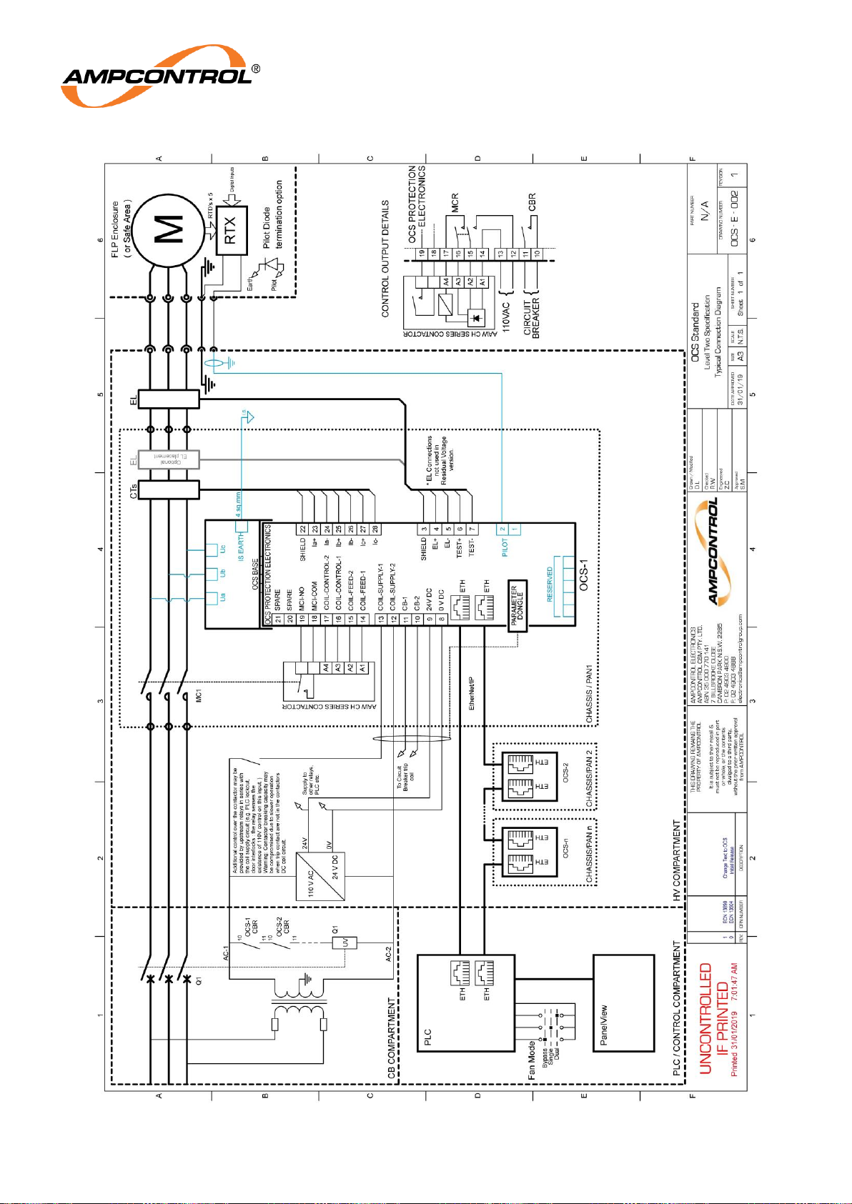
Ampcontrol Pty Ltd – ABN 28 000 915 542
OCS USER MANUAL
MAG-182 Version 6 – September/2020
Uncontrolled Copy - Refer to Ampcontrol Website for Latest Version
Page 58 of 72
APPROVED FOR EXTERNAL DISTRIBUTION
– PROPERTY OF AMPCONTROL PTY LTD
– NOT TO BE REPRODUCED IN PART
Page 59
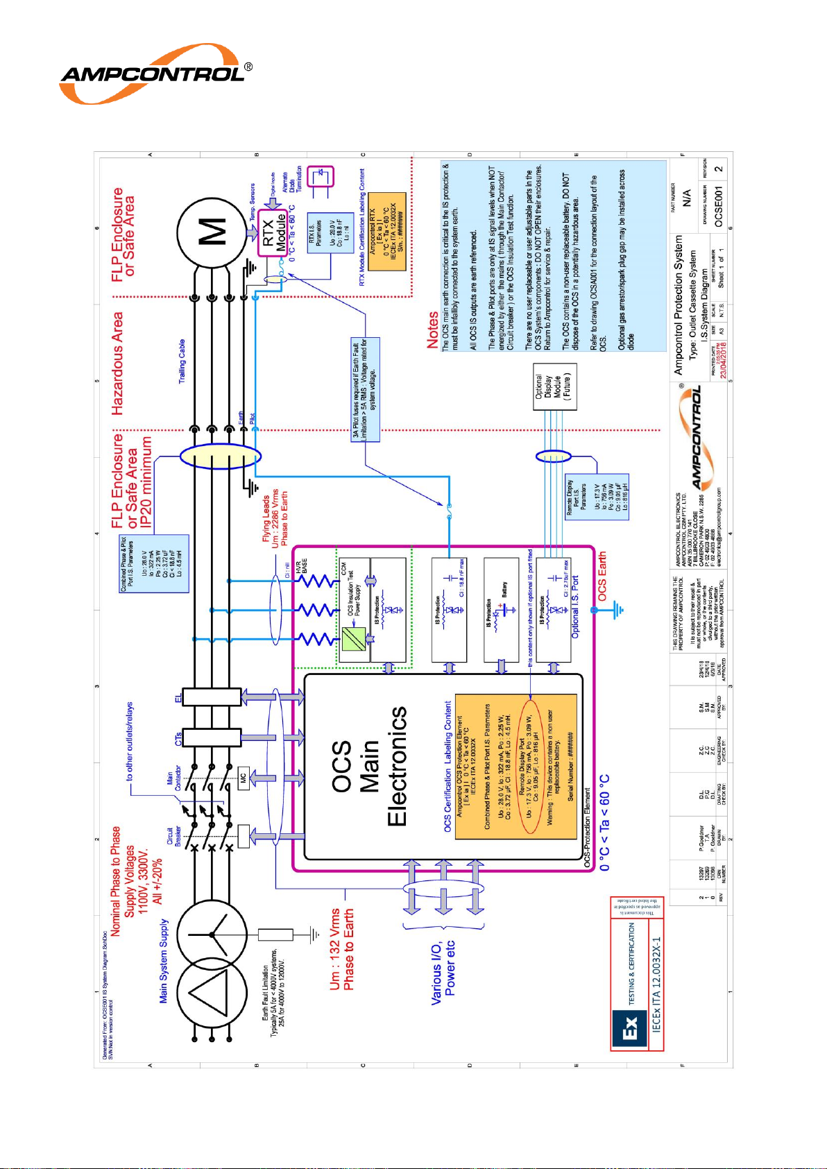
Ampcontrol Pty Ltd – ABN 28 000 915 542
OCS USER MANUAL
MAG-182 Version 6 – September/2020
Uncontrolled Copy - Refer to Ampcontrol Website for Latest Version
Page 59 of 72
APPROVED FOR EXTERNAL DISTRIBUTION
– PROPERTY OF AMPCONTROL PTY LTD
– NOT TO BE REPRODUCED IN PART
Page 60
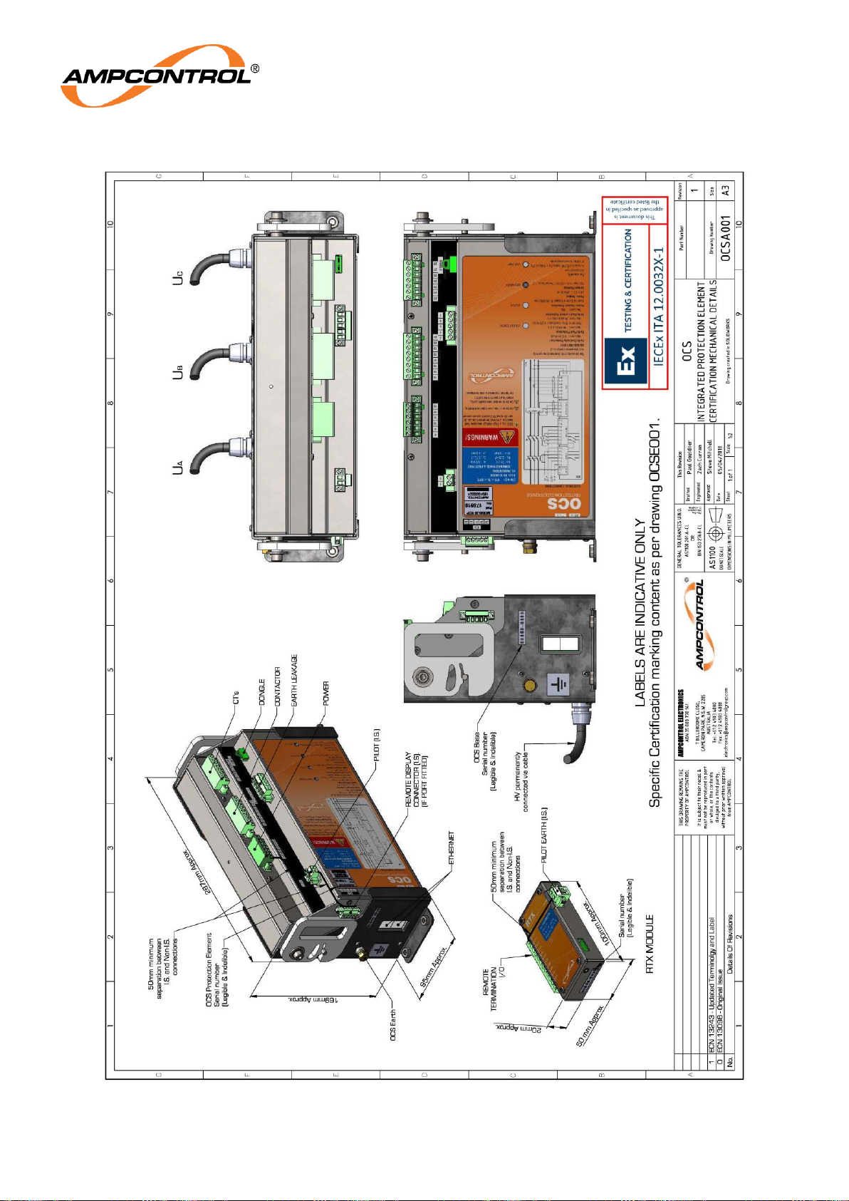
Ampcontrol Pty Ltd – ABN 28 000 915 542
OCS USER MANUAL
MAG-182 Version 6 – September/2020
Uncontrolled Copy - Refer to Ampcontrol Website for Latest Version
Page 60 of 72
APPROVED FOR EXTERNAL DISTRIBUTION
– PROPERTY OF AMPCONTROL PTY LTD
– NOT TO BE REPRODUCED IN PART
Page 61
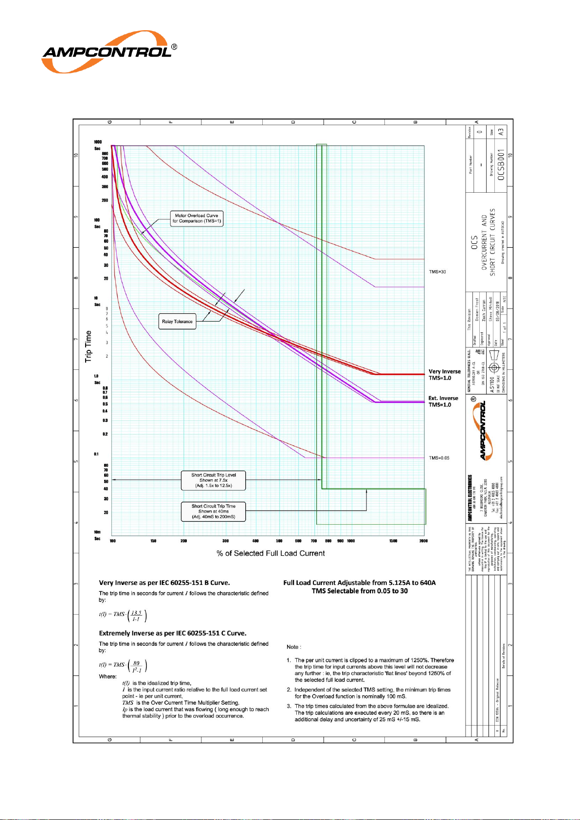
Ampcontrol Pty Ltd – ABN 28 000 915 542
OCS USER MANUAL
MAG-182 Version 6 – September/2020
Uncontrolled Copy - Refer to Ampcontrol Website for Latest Version
Page 61 of 72
APPROVED FOR EXTERNAL DISTRIBUTION
– PROPERTY OF AMPCONTROL PTY LTD
– NOT TO BE REPRODUCED IN PART
Page 62
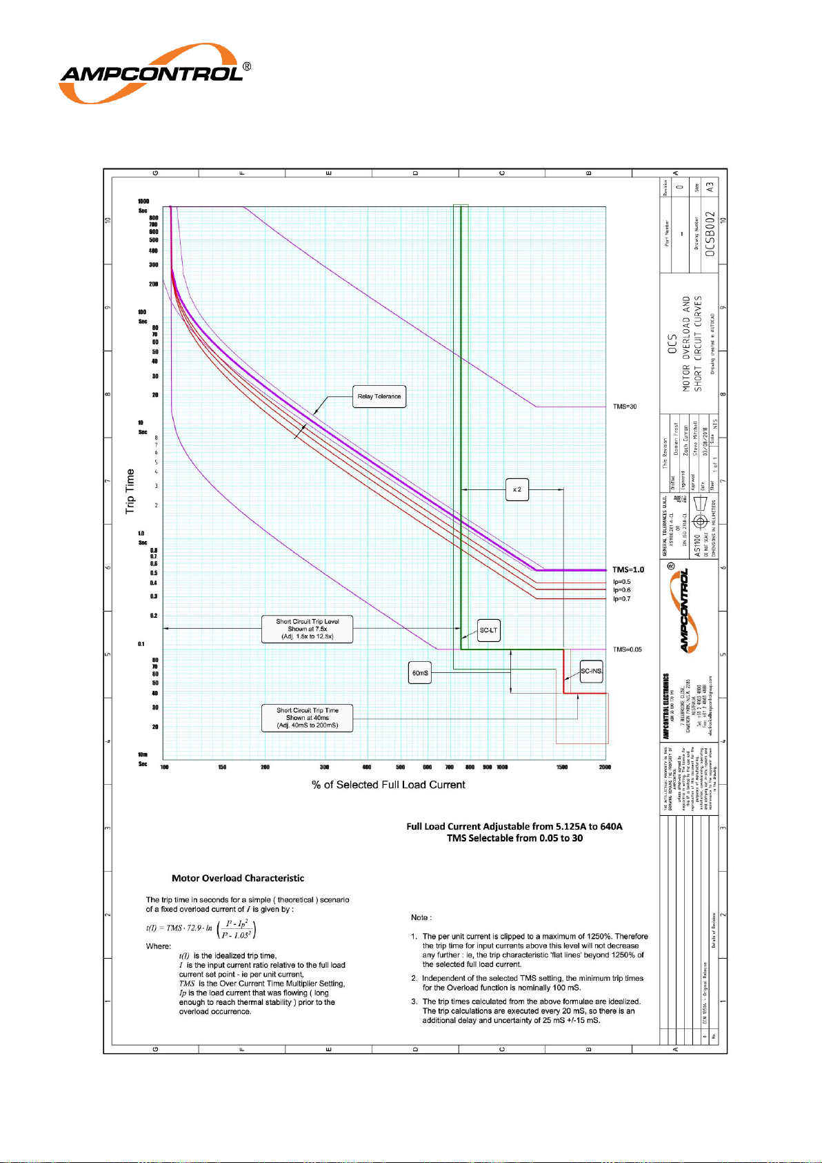
Ampcontrol Pty Ltd – ABN 28 000 915 542
OCS USER MANUAL
MAG-182 Version 6 – September/2020
Uncontrolled Copy - Refer to Ampcontrol Website for Latest Version
Page 62 of 72
APPROVED FOR EXTERNAL DISTRIBUTION
– PROPERTY OF AMPCONTROL PTY LTD
– NOT TO BE REPRODUCED IN PART
Page 63

Ampcontrol Pty Ltd – ABN 28 000 915 542
OCS USER MANUAL
MAG-182 Version 6 – September/2020
Uncontrolled Copy - Refer to Ampcontrol Website for Latest Version
Page 63 of 72
APPROVED FOR EXTERNAL DISTRIBUTION
– PROPERTY OF AMPCONTROL PTY LTD
– NOT TO BE REPRODUCED IN PART
APPENDIX C: APPROVALS
This appendix contains a copy of Issue No. 1 of the IECEx ITA 12.0032X certificate of conformity and
relevant attachments. For the most up-to-date copy of this certification refer to the http://iecex.iec.ch/
website.
Page 64
Ampcontrol Pty Ltd – ABN 28 000 915 542
OCS USER MANUAL
MAG-182 Version 6 – September/2020
Uncontrolled Copy - Refer to Ampcontrol Website for Latest Version
Page 64 of 72
APPROVED FOR EXTERNAL DISTRIBUTION
– PROPERTY OF AMPCONTROL PTY LTD
– NOT TO BE REPRODUCED IN PART
Page 65

Ampcontrol Pty Ltd – ABN 28 000 915 542
OCS USER MANUAL
MAG-182 Version 6 – September/2020
Uncontrolled Copy - Refer to Ampcontrol Website for Latest Version
Page 65 of 72
APPROVED FOR EXTERNAL DISTRIBUTION
– PROPERTY OF AMPCONTROL PTY LTD
– NOT TO BE REPRODUCED IN PART
Page 66

Ampcontrol Pty Ltd – ABN 28 000 915 542
OCS USER MANUAL
MAG-182 Version 6 – September/2020
Uncontrolled Copy - Refer to Ampcontrol Website for Latest Version
Page 66 of 72
APPROVED FOR EXTERNAL DISTRIBUTION
– PROPERTY OF AMPCONTROL PTY LTD
– NOT TO BE REPRODUCED IN PART
Page 67
Ampcontrol Pty Ltd – ABN 28 000 915 542
OCS USER MANUAL
MAG-182 Version 6 – September/2020
Uncontrolled Copy - Refer to Ampcontrol Website for Latest Version
Page 67 of 72
APPROVED FOR EXTERNAL DISTRIBUTION
– PROPERTY OF AMPCONTROL PTY LTD
– NOT TO BE REPRODUCED IN PART
Page 68
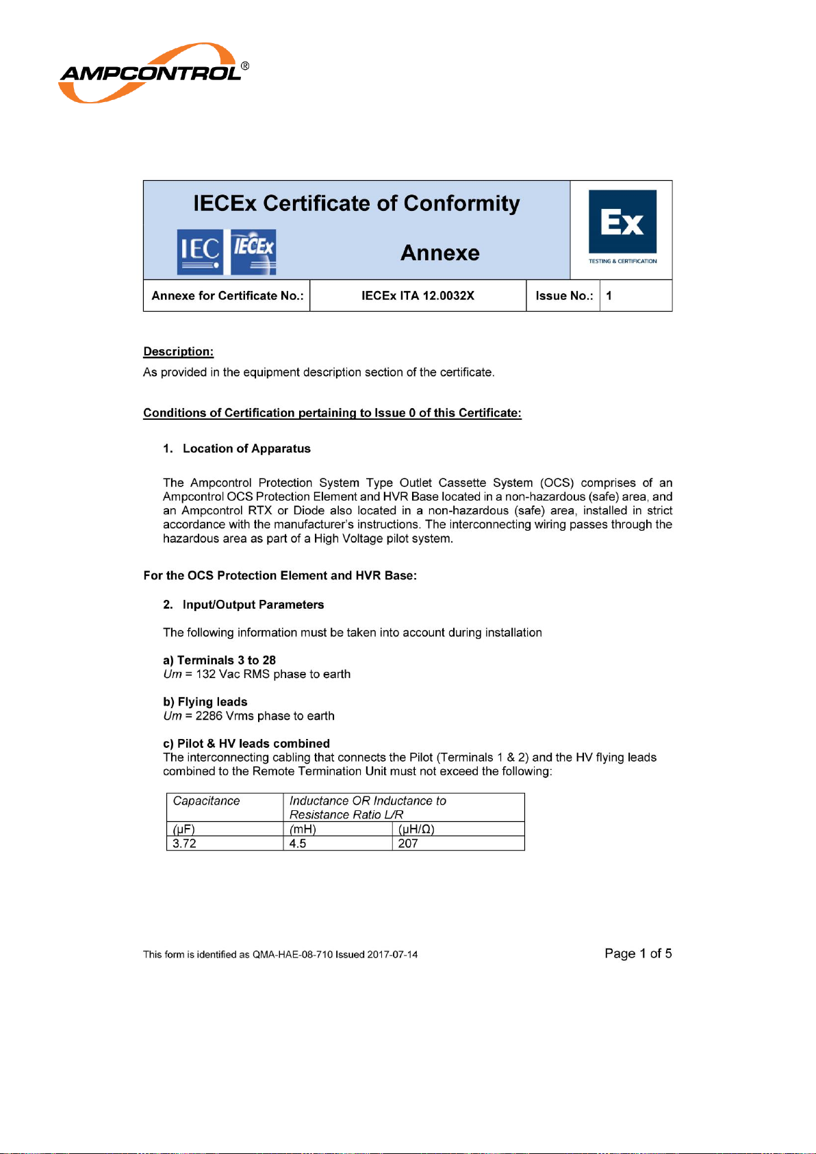
Ampcontrol Pty Ltd – ABN 28 000 915 542
OCS USER MANUAL
MAG-182 Version 6 – September/2020
Uncontrolled Copy - Refer to Ampcontrol Website for Latest Version
Page 68 of 72
APPROVED FOR EXTERNAL DISTRIBUTION
– PROPERTY OF AMPCONTROL PTY LTD
– NOT TO BE REPRODUCED IN PART
Page 69
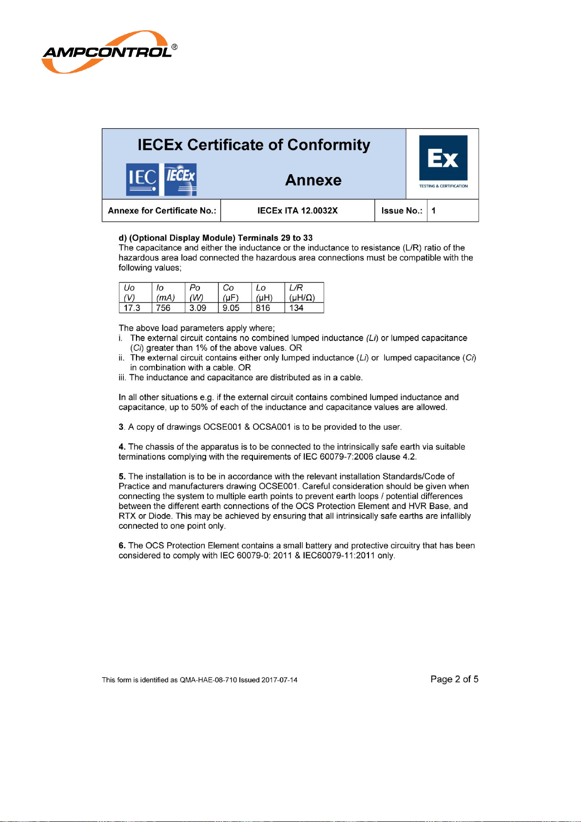
Ampcontrol Pty Ltd – ABN 28 000 915 542
OCS USER MANUAL
MAG-182 Version 6 – September/2020
Uncontrolled Copy - Refer to Ampcontrol Website for Latest Version
Page 69 of 72
APPROVED FOR EXTERNAL DISTRIBUTION
– PROPERTY OF AMPCONTROL PTY LTD
– NOT TO BE REPRODUCED IN PART
Page 70
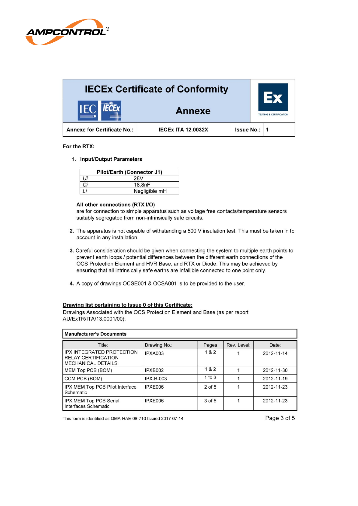
Ampcontrol Pty Ltd – ABN 28 000 915 542
OCS USER MANUAL
MAG-182 Version 6 – September/2020
Uncontrolled Copy - Refer to Ampcontrol Website for Latest Version
Page 70 of 72
APPROVED FOR EXTERNAL DISTRIBUTION
– PROPERTY OF AMPCONTROL PTY LTD
– NOT TO BE REPRODUCED IN PART
Page 71
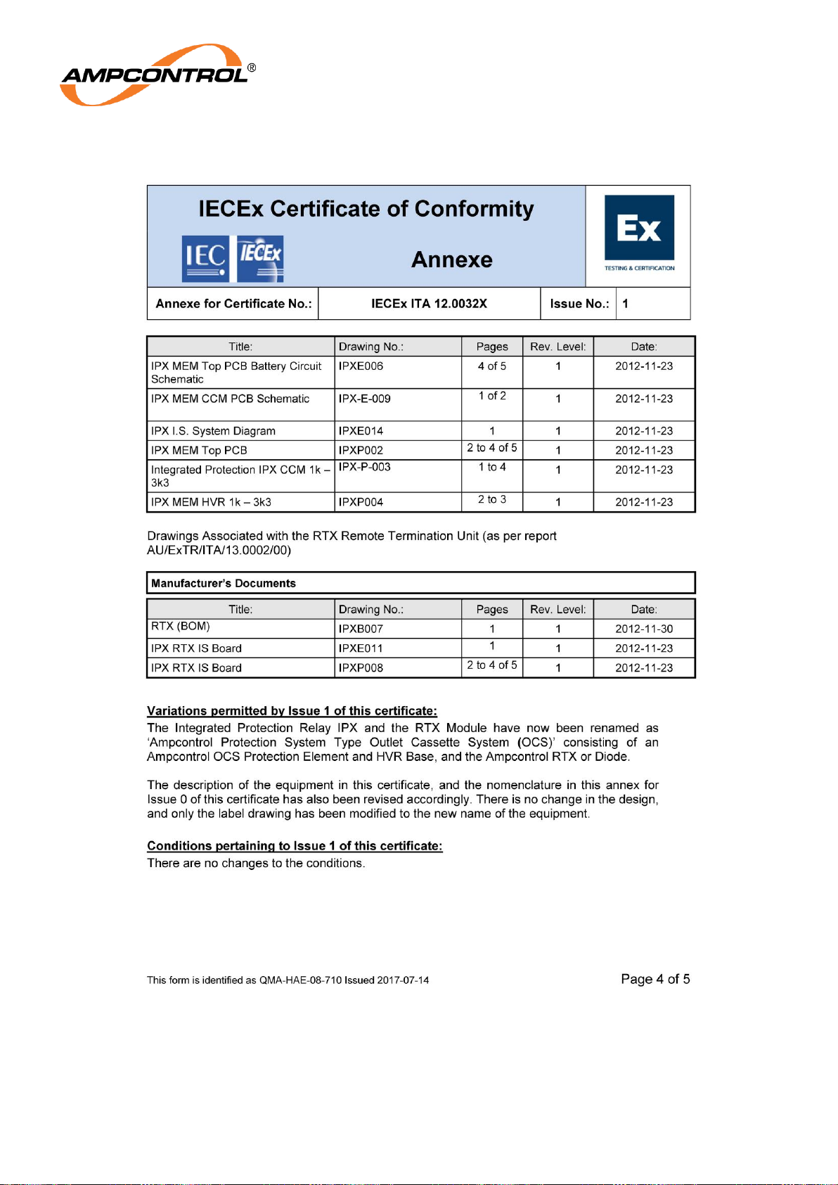
Ampcontrol Pty Ltd – ABN 28 000 915 542
OCS USER MANUAL
MAG-182 Version 6 – September/2020
Uncontrolled Copy - Refer to Ampcontrol Website for Latest Version
Page 71 of 72
APPROVED FOR EXTERNAL DISTRIBUTION
– PROPERTY OF AMPCONTROL PTY LTD
– NOT TO BE REPRODUCED IN PART
Page 72
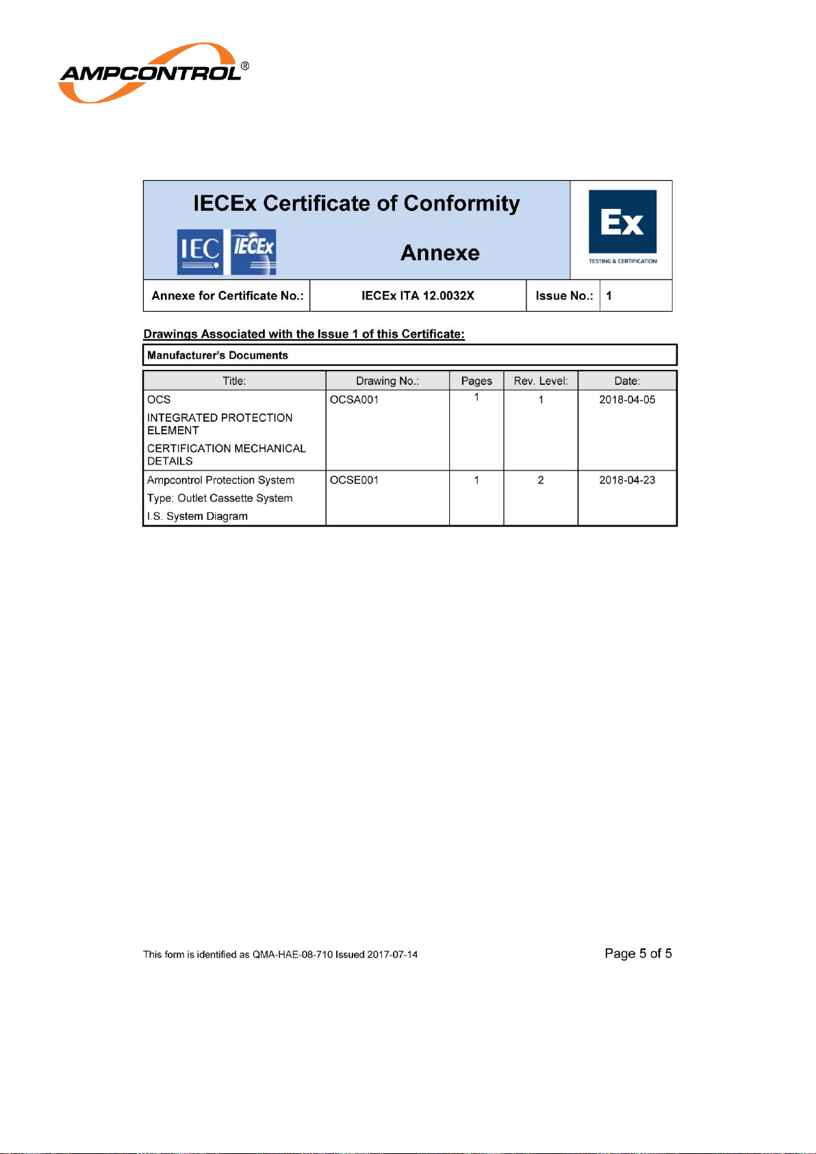
Ampcontrol Pty Ltd – ABN 28 000 915 542
OCS USER MANUAL
MAG-182 Version 6 – September/2020
Uncontrolled Copy - Refer to Ampcontrol Website for Latest Version
Page 72 of 72
APPROVED FOR EXTERNAL DISTRIBUTION
– PROPERTY OF AMPCONTROL PTY LTD
– NOT TO BE REPRODUCED IN PART
 Loading...