

Page 1
Version: 3, December 2019
Designed and manufactured in Australia by Ampcontrol Pty Ltd
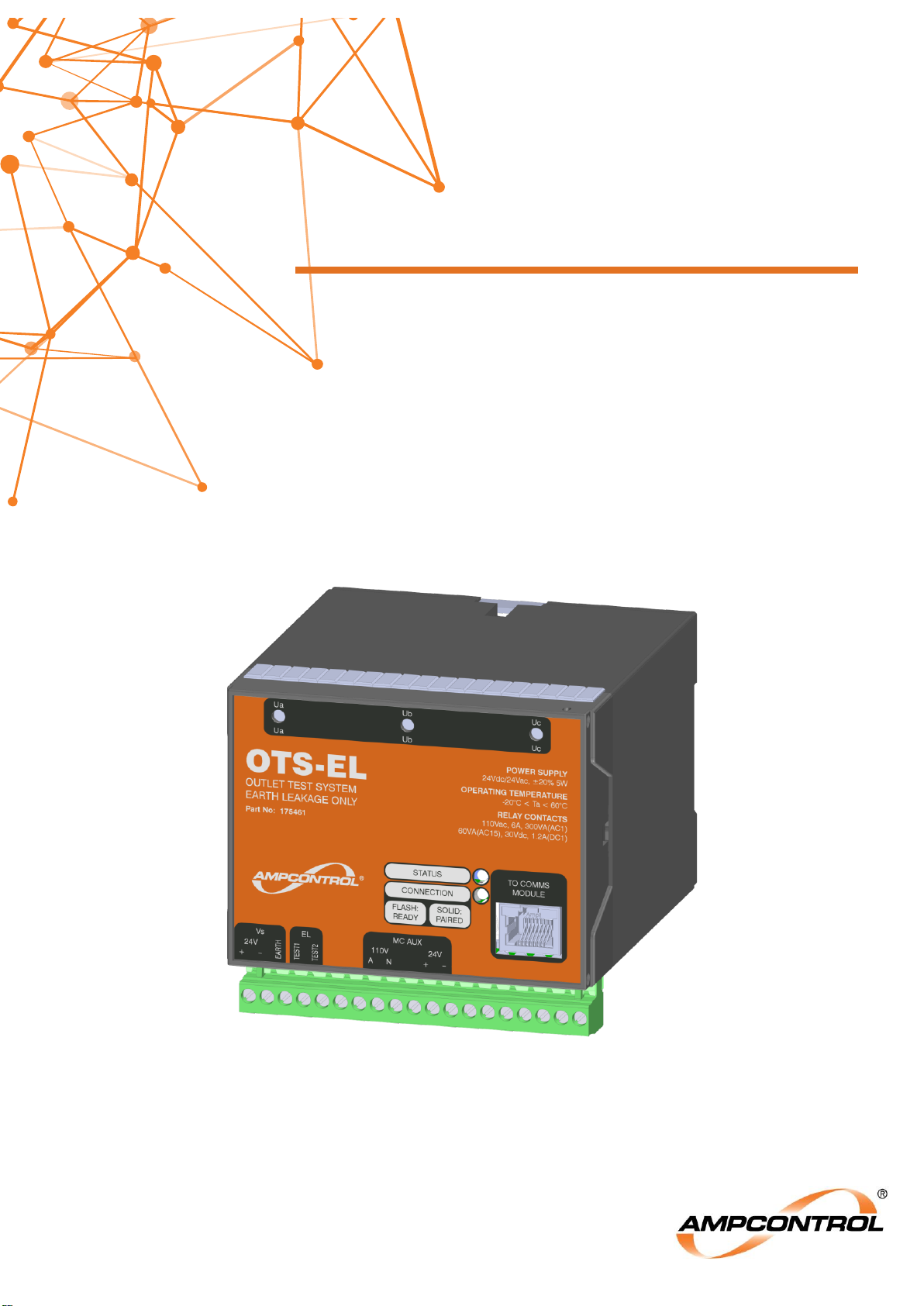
OTS-EL
OUTLET TEST SYSTEM – EARTH LEAKAGE
User Manual
Page 2
Ampcontrol Pty Ltd – ABN 28 000 915 542
OTS-EL USER MANUAL
MAG-205 Version 3 – DEC/19
Uncontrolled Copy - Refer to Ampcontrol Website for Latest Version
Page 2 of 23
APPROVED FOR EXTERNAL DISTRIBUTION
– PROPERTY OF AMPCONTROL PTY LTD
– NOT TO BE REPRODUCED IN PART
WARNING!
The warning symbol highlights a potential risk of injury or death.
Please share these warnings with other operators.
CAUTION!
The caution symbol highlights a potential risk of damage to
equipment.
Please share these cautions with other operators.
NOTE
The note symbol highlights key information.
Please share these notes with other operators.
ENVIRO
The enviro (environmental) symbol highlights areas which may have an
impact on the surrounding fauna and/or flora.
Page 3

Ampcontrol Pty Ltd – ABN 28 000 915 542
OTS-EL USER MANUAL
MAG-205 Version 3 – DEC/19
Uncontrolled Copy - Refer to Ampcontrol Website for Latest Version
Page 3 of 23
APPROVED FOR EXTERNAL DISTRIBUTION
– PROPERTY OF AMPCONTROL PTY LTD
– NOT TO BE REPRODUCED IN PART
Copyright Notice
The Ampcontrol Outlet Test System – Earth Leakage (OTS-EL) described in this document is the
property of AMPCONTROL PTY LTD. It is furnished under a license agreement and is to be used only in
accordance with the terms of the agreement.
No part of the hardware or documentation may be reproduced, transmitted, transcribed, stored in a
retrieval system, or translated into any language or computer language, in any form or by any means,
without prior written permission of AMPCONTROL PTY LTD.
Disclaimer
While every effort has been made to assure the accuracy and clarity of this document, AMPCONTROL
PTY LTD assumes no liability resulting from any omissions in this document, or from misuse of the
information obtained herein. The information in this document has been carefully checked and is
believed to be entirely reliable with all of the necessary information included. AMPCONTROL PTY LTD
reserves the right to make changes to any products described herein to improve reliability, function, or
design, and reserves the right to revise this document and make changes from time to time in content
hereof with no obligation to notify any persons of revisions or changes. AMPCONTROL PTY LTD does
not assume any liability arising out of the application or any use of any product or circuit described
herein; neither does it convey license under its patent rights or the rights of others.
Before You Begin
Thank you for purchasing the Ampcontrol OTS-EL.
WARNING!
In the interests of safety and correct equipment operation, please
take the time to read and understand the content in this manual.
Ampcontrol Contact Details
7 Billbrooke Close, Cameron Park, NSW, 2285
P +61 1300 267 373 | F +61 2 4903 4888
EMAIL: [email protected]
WEB: ampcontrolgroup.com
Page 4

Ampcontrol Pty Ltd – ABN 28 000 915 542
OTS-EL USER MANUAL
MAG-205 Version 3 – DEC/19
Uncontrolled Copy - Refer to Ampcontrol Website for Latest Version
Page 4 of 23
APPROVED FOR EXTERNAL DISTRIBUTION
– PROPERTY OF AMPCONTROL PTY LTD
– NOT TO BE REPRODUCED IN PART
TABLE OF CONTENTS
1 SAFETY AND OTHER WARNINGS .................................................................. 6
1.1 Safe Use of Equipment .............................................................................. 6
2 RECEIVING AND STORAGE ............................................................................ 7
2.1 Receiving ................................................................................................... 7
2.2 Inspection .................................................................................................. 7
2.3 Storage after Delivery ................................................................................ 7
2.4 Unpacking of Equipment ............................................................................ 7
3 PRODUCT OVERVIEW .................................................................................... 8
3.1 Description ................................................................................................. 8
3.2 Key Features ............................................................................................. 8
3.3 Application ................................................................................................. 8
3.4 Supplementary Documents ........................................................................ 8
4 INSTALLATION ................................................................................................. 9
4.1 General Warnings ...................................................................................... 9
4.2 Mandatory Installation Practices ................................................................ 9
4.3 Mechanical Installation Information .......................................................... 10
4.4 Electrical Installation Information ............................................................. 13
5 PRODUCT OPERATION ................................................................................. 18
5.1 Earth Leakage Protection Function Test .................................................. 19
6 OPERATIONAL INTERFACE .......................................................................... 20
6.1 OTS-EL Operational Interface .................................................................. 20
6.2 OTS Comms Module Operational Interface ............................................. 21
7 SERVICE, MAINTENANCE & DISPOSAL ....................................................... 22
7.1 Equipment Service ................................................................................... 22
7.2 Equipment Maintenance .......................................................................... 22
7.3 Disposal ................................................................................................... 23
8 SPECIFICATIONS .......................................................................................... 23
9 EQUIPMENT LIST .......................................................................................... 23
Page 5

Ampcontrol Pty Ltd – ABN 28 000 915 542
OTS-EL USER MANUAL
MAG-205 Version 3 – DEC/19
Uncontrolled Copy - Refer to Ampcontrol Website for Latest Version
Page 5 of 23
APPROVED FOR EXTERNAL DISTRIBUTION
– PROPERTY OF AMPCONTROL PTY LTD
– NOT TO BE REPRODUCED IN PART
TABLE OF FIGURES
Figure 4.1: OTS-EL System Overview .................................................................................................... 10
Figure 4.2: OTS-EL Dimensions ............................................................................................................. 10
Figure 4.3: OTS-EL Terminal Layout ...................................................................................................... 11
Figure 4.4: OTS Comms Module ............................................................................................................ 12
Figure 4.5: OTS Comms Module and External Label .............................................................................. 12
Figure 4.6: Electrical Connections - OTS-EL Circuit Diagram ................................................................. 13
Figure 4.7: Electrical Connections – OTS-EL Power Supply ................................................................... 14
Figure 4.8: Electrical Connections: Internal HV Barrier ........................................................................... 14
Figure 4.9: Electrical Connections: Comms Module................................................................................ 15
Figure 4.10: Electrical Connections – EL Test ........................................................................................ 16
Figure 4.11: Electrical Connections – MC Auxiliary Input (Option 1) ....................................................... 17
Figure 4.12: Electrical Connections – MC Auxiliary Input (Option 2) ....................................................... 17
Figure 6.1: OTS-EL Operational Interface .............................................................................................. 20
Figure 6.2: Comms Module Operational Interface .................................................................................. 21
TABLE OF TABLES
Table 1: OTS-EL Terminal Designators .................................................................................................. 11
Table 2: OTS-EL Fascia LED Operation ................................................................................................. 20
Table 3: OTS-EL Comms Module LED Operation .................................................................................. 21
Page 6

Ampcontrol Pty Ltd – ABN 28 000 915 542
OTS-EL USER MANUAL
MAG-205 Version 3 – DEC/19
Uncontrolled Copy - Refer to Ampcontrol Website for Latest Version
Page 6 of 23
APPROVED FOR EXTERNAL DISTRIBUTION
– PROPERTY OF AMPCONTROL PTY LTD
– NOT TO BE REPRODUCED IN PART
1 SAFETY AND OTHER WARNINGS
For safety reasons, the OTS-EL must be installed, operated and serviced only by competent personnel.
Please read and understand this instruction manual completely before installing, operating or servicing
this equipment. Failure to install or operate this instrument in accordance with the instructions contained
in this manual may create hazardous operating conditions.
1.1 Safe Use of Equipment
The equipment supplied has been designed and manufactured to ensure safe operation. The equipment
must only be used within the design parameters.
The instructions within this manual must be observed as an aid towards achieving the safest possible
installation.
Persons responsible for installation, maintenance, or operation, must observe the following
instructions:
1.1.1 Changes to Equipment
Changes in the design and modifications to the equipment are not permitted. Unauthorised changes
made to the hardware or operating firmware will void the manufacturer's warranty, and may
compromise the integrity of the system into which it is installed and other connected equipment.
1.1.2 Equipment Knowledge
Experience with, or understanding of, this equipment is essential for the safe installation and removal of
the equipment. Therefore, please read and understand this manual prior to use. Competency based
training courses are recommended and are available on request.
1.1.3 Manual Handling
Precautions have been taken to ensure all equipment is safe to handle and free from sharp edges.
However, care should always be taken when handling enclosures and gloves should be worn.
1.1.4 Installation
Correct operation and safety depend on the Outlet Test System and associated equipment being
installed correctly. Mechanical and or electrical installation and maintenance of plant and equipment
must only be carried out by appropriately qualified personnel and must be tested thoroughly prior to
operation.
1.1.5 Operation
The OTS-EL is not a primary safety device: it is periodically operated to ensure the correct operation of
the primary earth leakage protection on an outlet. It is therefore necessary that it is operated only by
trained and competent personnel who can correctly interpret and verify the test results obtained
through the use of the OTS-EL.
Page 7

Ampcontrol Pty Ltd – ABN 28 000 915 542
OTS-EL USER MANUAL
MAG-205 Version 3 – DEC/19
Uncontrolled Copy - Refer to Ampcontrol Website for Latest Version
Page 7 of 23
APPROVED FOR EXTERNAL DISTRIBUTION
– PROPERTY OF AMPCONTROL PTY LTD
– NOT TO BE REPRODUCED IN PART
2 RECEIVING AND STORAGE
2.1 Receiving
All possible precautions are taken to protect the equipment against damage or losses during shipment;
however, before accepting delivery, check all items against the packing list or bill of loading. If there is
evidence of physical damage, notify Ampcontrol immediately.
Notify Ampcontrol immediately in the case of any discrepancies to the packing list. Keep a record of any
claims and correspondence. Photographs are recommended.
Where practicable do not remove protective covers prior to installation unless there are indications of
damage. Boxes opened for inspection and inventory should be carefully repacked to ensure protection of
the contents or else the parts should be packaged and stored in a safe place. Examine all packing
boxes, wrappings and covers for items attached to them, retain and store any approval documentation
for your safety file as applicable prior to wrapping being discarded.
2.2 Inspection
Equipment that is found to be damaged or has been modified away from its published specifications
must not be used. Please contact Ampcontrol if the equipment is suspected to be different than that
ordered or if it does not match the published specifications.
2.3 Storage after Delivery
When the equipment is not to be installed immediately, proper storage is important to ensure protection
of equipment and validity of warranty.
All equipment should be stored indoors between 0-40˚C, preferably on shelves and protected from
moisture and sunlight.
2.4 Unpacking of Equipment
The method of packing used will depend on the size and quantity of the equipment. The following
cautions should be interpreted as appropriate.
CAUTION!
Take care when unpacking crates as the
contents may have shifted during transport.
ENVIRO
The disposal of packaging materials, replaced parts, or components
must comply with environmental restrictions without polluting the soil,
air or water.
Ensure that any timber and cardboard used as packaging is disposed
of in a safe and environmentally responsible manner.
Where possible, dispose of all waste products i.e. oils, metals, plastic
and rubber products by using an approved recycling service centre.
Page 8

Ampcontrol Pty Ltd – ABN 28 000 915 542
OTS-EL USER MANUAL
MAG-205 Version 3 – DEC/19
Uncontrolled Copy - Refer to Ampcontrol Website for Latest Version
Page 8 of 23
APPROVED FOR EXTERNAL DISTRIBUTION
– PROPERTY OF AMPCONTROL PTY LTD
– NOT TO BE REPRODUCED IN PART
3 PRODUCT OVERVIEW
3.1 Description
The Ampcontrol Outlet Test System – Earth Leakage (OTS-EL) provides a fully automated outlet earth
leakage testing facility. The OTS-EL completely eliminates paper-based record keeping by concurrently
updating a historical database with the latest test data.
The OTS-EL is comprised of an OTS-EL module, embedded within the outlet electrics, and an OTS
Comms Module, mounted on the door to provide Bluetooth connectivity to the outlet tester.
All tests are initiated wirelessly via the OTS Application Software, which is installed on compatible
Bluetooth enabled devices. Each outlet is able to be individually targeted.
All local test records are managed within the OTS Application Software until the tablet performs an
authorised sync with the AWARE cloud storage. When this occurs all local test reports are uploaded to
the cloud, and then all Assets and Users are refreshed for selected site. All OTS test records can be
accessed by anyone with internet access and authorisation (user account).
The OTS-EL will measure both the contactor opening time in addition to the true earth leakage clearing
time (time for back EMF voltages to fall below ELV).
3.2 Key Features
The OTS-EL has the following key features:
Fully automated, outlet protection function testing
Wireless outlet testing
Earth Leakage (EL) protection testing (contactor operating and back EMF clearing times)
Test data logging (Uploads to cloud storage)
DIN rail mounted
3.3 Application
The OTS-EL System can be installed into Ampcontrol Substations, Distribution Boards and Outlet
Control Boxes. The OTS-EL greatly simplifies the statutory testing process, performing a hands-free,
automated testing function whilst simultaneously providing a comprehensive record management tool.
3.4 Supplementary Documents
The OTS-EL User Manual is expected to be read in conjunction with the following documents:
MAG-199 OTS Application User Manual
MAG-204 OTS Dashboard User Manual
Page 9

Ampcontrol Pty Ltd – ABN 28 000 915 542
OTS-EL USER MANUAL
MAG-205 Version 3 – DEC/19
Uncontrolled Copy - Refer to Ampcontrol Website for Latest Version
Page 9 of 23
APPROVED FOR EXTERNAL DISTRIBUTION
– PROPERTY OF AMPCONTROL PTY LTD
– NOT TO BE REPRODUCED IN PART
4 INSTALLATION
4.1 General Warnings
These instructions have been designed to assist users of the OTS-EL with installation.
Before the OTS-EL can be installed, there are a number of things that need to be considered and
understood to prevent incorrect or unsafe operation of the OTS-EL or the system into which it is
installed.
Along with relevant competence, and an understanding of the target application, the following points
should be considered:
4.1.1 Ensure that the information provided in this user manual is fully understood.
It is extremely important that the limitations and functionality of the OTS - EL are understood to prevent
incorrect installation or use, creating a potentially dangerous risk. If in doubt as to the nature of the
limitations or their implication, consult a competent authority such as a supervisor or Ampcontrol
technical representative.
4.1.2 Ensure that the application into which the OTS-EL is being installed has been
properly defined, designed and approved.
Any system intended to mitigate the risk of injury needs to be properly designed and implemented.
Such a system must be the result of structured risk analysis with the outcomes used to define the
system requirements. These requirements, in turn, will guide the choice of instrumentation, logic
solvers and actuators needed to implement the system. Understanding the needs of the system will
ensure proper selection of equipment.
4.1.3 Ensure that the OTS-EL will properly perform the required functions within the
system design.
It is important to understand how the OTS-EL is intended to interact with other equipment within a
system. For safe and reliable use, it is crucial that neither the OTS-EL logical operation nor its
signalling be compromised by incompatibilities with connected equipment.
4.1.4 Modifications of any form to the Outlet Test System are prohibited.
If modifications of any form are made to the OTS-EL, the equipment may no longer be fit for use. If any
modifications or damage to the OTS-EL is evident, do not use the equipment and contact Ampcontrol
for advice.
4.2 Mandatory Installation Practices
The following information must be adhered to when installing the OTS-EL. Failure to adhere to this
information may give rise to unsafe operation.
Using the OTS-EL in a manner that exceeds its electrical or functional specifications, or in a way that is
contrary to its operating restrictions, may create risks to personnel and/or equipment resulting in injury or
death.
The OTS-EL must be supplied by a regulated voltage within the specified range.
The installation of the OTS-EL must be carried out by suitably trained and qualified personnel.
Identification labels fixed to the OTS-EL must not be damaged, removed or covered.
The installation is to be in accordance with the relevant installation Standards/Codes of Practice.
Modifications must not be made to any part of the OTS-EL. Modifications to its construction will
render the unit non-compliant.
Complete and accurate records of the installation must be retained for warranty purposes.
Page 10
Ampcontrol Pty Ltd – ABN 28 000 915 542
OTS-EL USER MANUAL
MAG-205 Version 3 – DEC/19
Uncontrolled Copy - Refer to Ampcontrol Website for Latest Version
Page 10 of 23
APPROVED FOR EXTERNAL DISTRIBUTION
– PROPERTY OF AMPCONTROL PTY LTD
– NOT TO BE REPRODUCED IN PART
4.3 Mechanical Installation Information
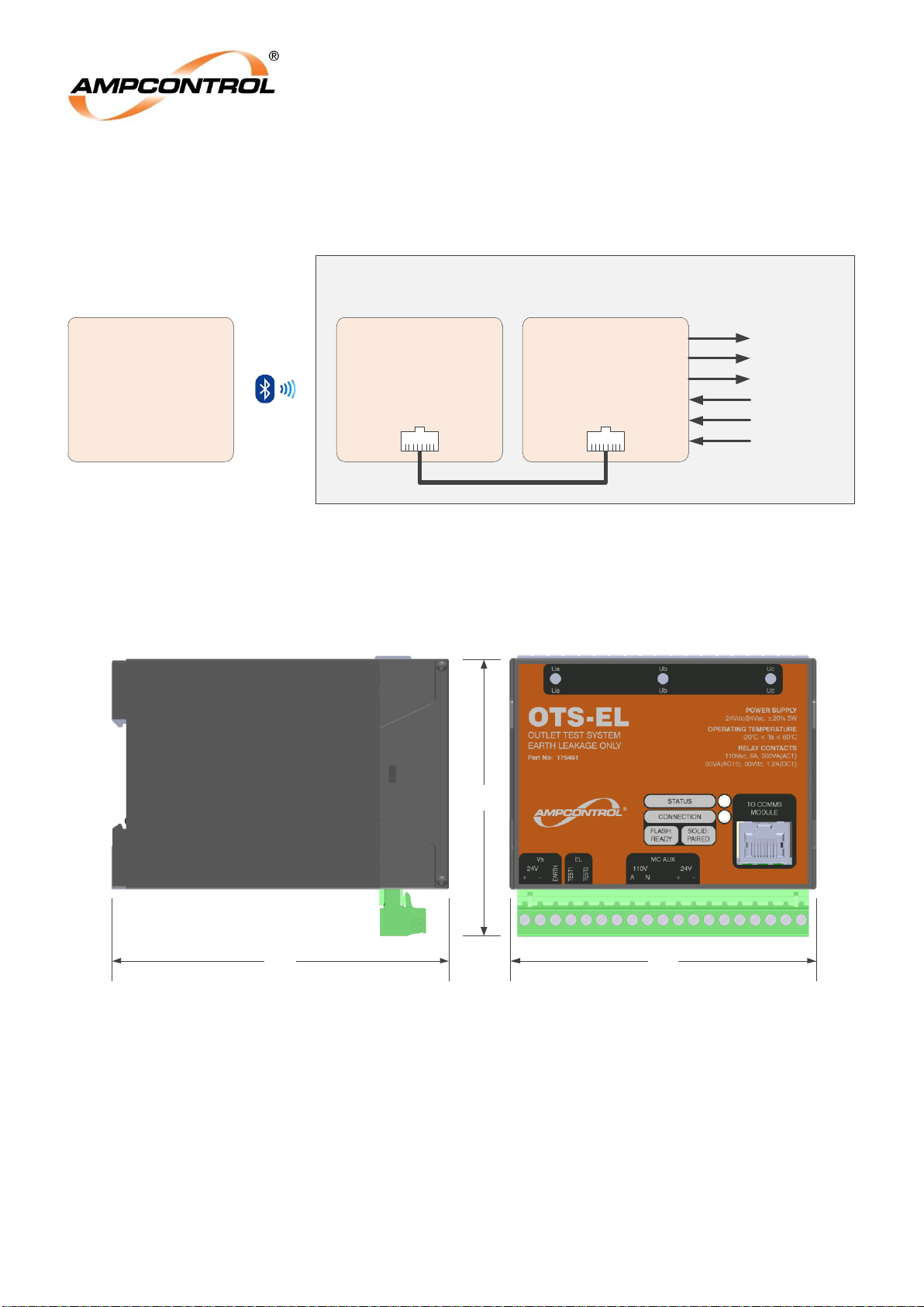
The OTS-EL is comprised of an OTS-EL Test module and an OTS Comms Module.
Figure 4.1: OTS-EL System Overview
4.3.1 OTS-EL Mechanical Installation Information
Figure 4.2: OTS-EL Dimensions
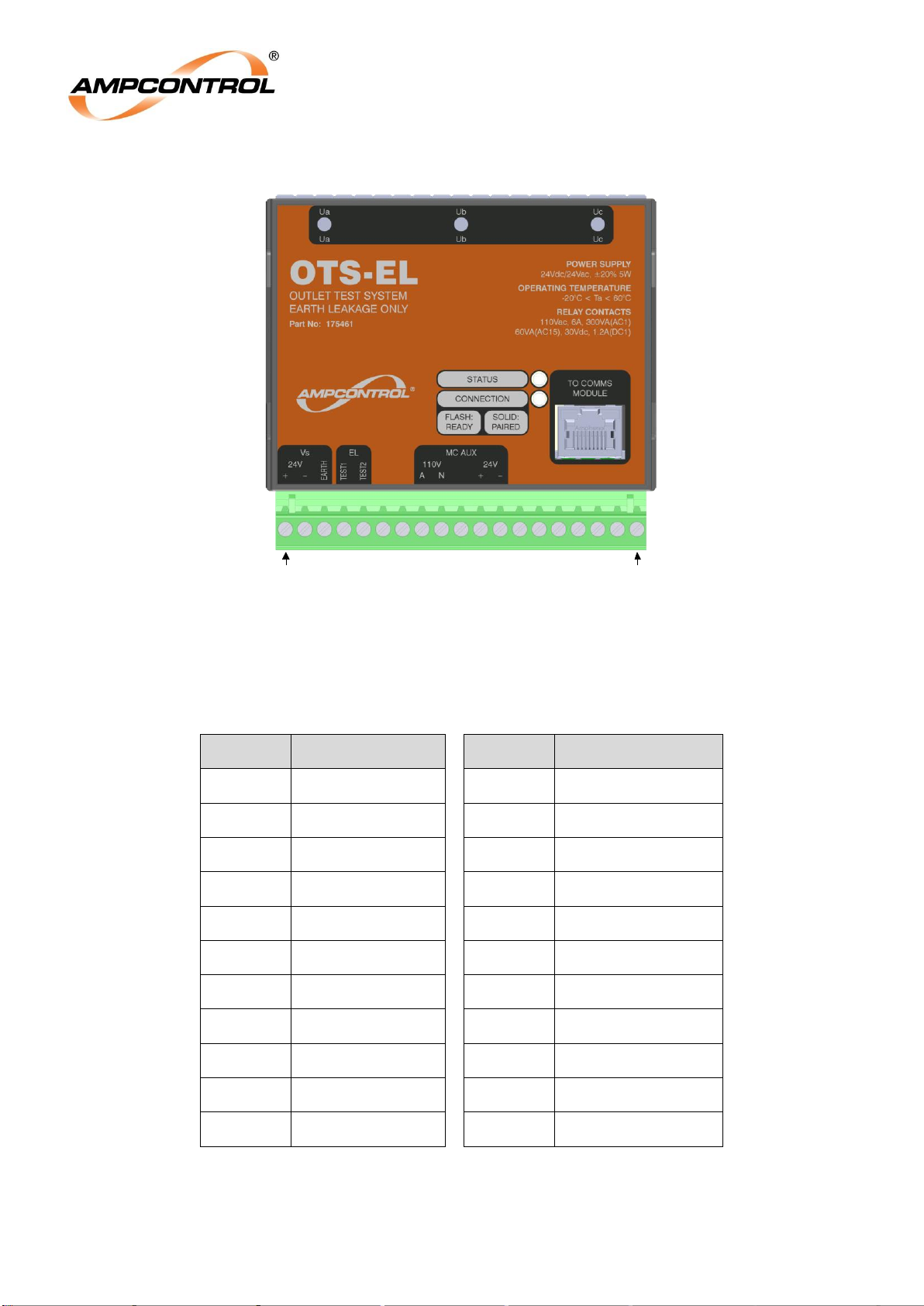
The OTS-EL Test module performs all the test actuation and measurements. It is a DIN Rail mounted
unit that interfaces with the outlet electrics. The terminal layout and description is shown in Figure 4.3
and
Table 1 respectively.
Outlet Enclosure
OTS Application
Software
Installed on
Bluetooth Enabled
Compatible Device
OTS
Comms Module
(Door Mounted)
OTS-EL
Module
Test Outputs
Result
Monitoring
91
110 100
Page 11
Ampcontrol Pty Ltd – ABN 28 000 915 542
OTS-EL USER MANUAL
MAG-205 Version 3 – DEC/19
Uncontrolled Copy - Refer to Ampcontrol Website for Latest Version
Page 11 of 23
APPROVED FOR EXTERNAL DISTRIBUTION
– PROPERTY OF AMPCONTROL PTY LTD
– NOT TO BE REPRODUCED IN PART
Figure 4.3: OTS-EL Terminal Layout
Table 1: OTS-EL Terminal Designators
Number
Designator
Number
Designator
1
Vs +
12
MC AUX -
2
Vs -
13
SPARE
3
Earth
14
SPARE
4
EL Test 1
15
SPARE
5
EL Test 2
16
SPARE
6
SPARE
17
SPARE
7
SPARE
18
SPARE
8
MC AUX 110V A
19
SPARE
9
MC AUX 110V N
Ua
Barrier Connection
10
SPARE
Ub
Barrier Connection
11
MC AUX +
Uc
Barrier Connection
1
Ua Ub Uc
19
Page 12
Ampcontrol Pty Ltd – ABN 28 000 915 542
OTS-EL USER MANUAL
MAG-205 Version 3 – DEC/19
Uncontrolled Copy - Refer to Ampcontrol Website for Latest Version
Page 12 of 23
APPROVED FOR EXTERNAL DISTRIBUTION
– PROPERTY OF AMPCONTROL PTY LTD
– NOT TO BE REPRODUCED IN PART
4.3.2 OTS Comms Module Mechanical Installation Information
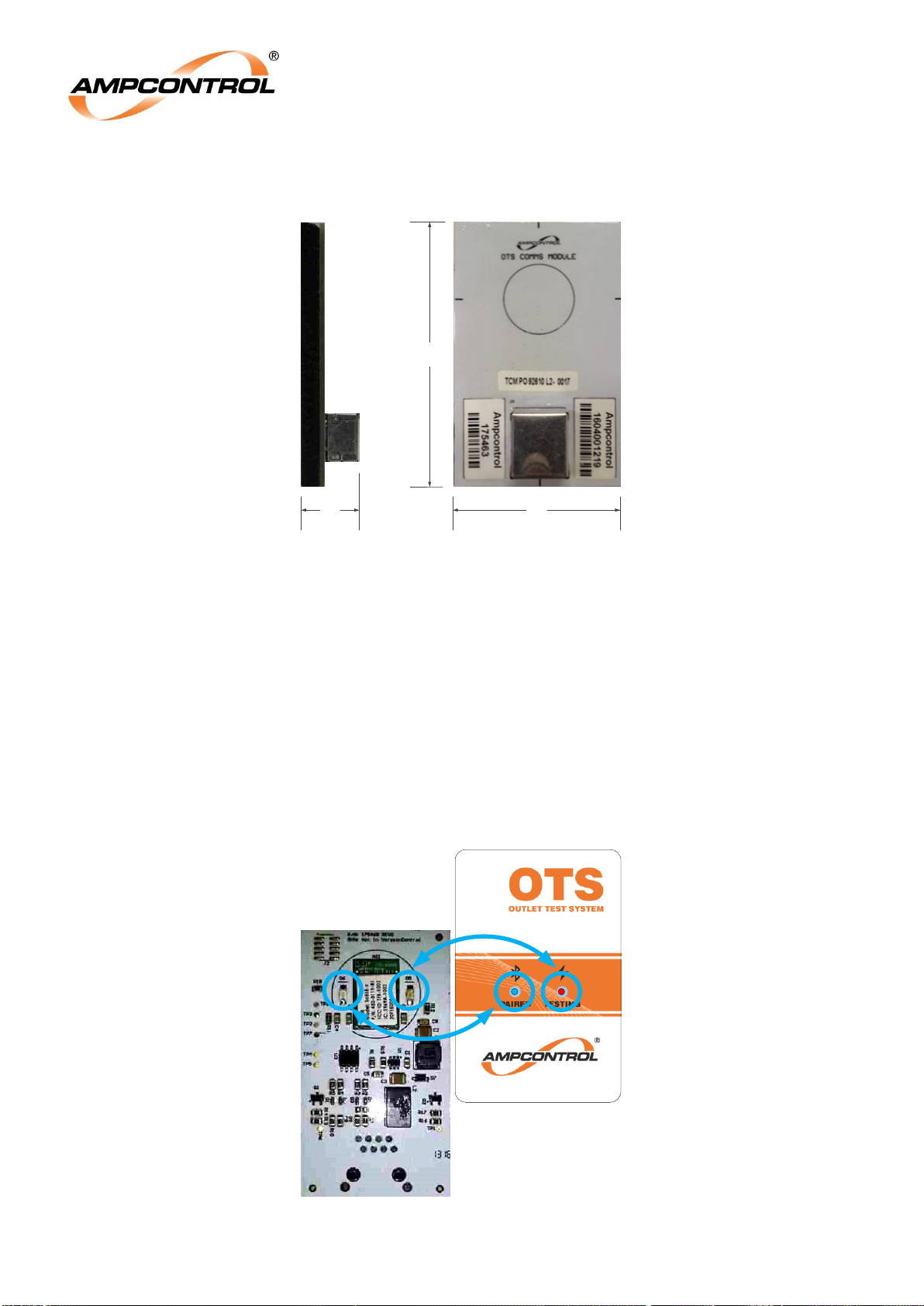
Figure 4.4: OTS Comms Module
The Comms module provides Bluetooth connectivity to the Tester. It is intended to be mounted onto
the back of an outlet door or enclosure, covering a 22.5mm OD hole. The hole needs to align with the
PCB aerial on the Comms module. Without this hole, the steel of the enclosure would form a shield,
preventing Bluetooth communications to the tester. To improve the connectivity of the Bluetooth device,
the hole in the enclosure should be positioned such that it faces the location where the testing officer is
most likely to stand when initiating the test procedure.
The Communications Module must be oriented with the RJ45 port pointing downwards to ensure both
LEDs on the Comms Module align with their corresponding position on the external label.
To install the Comms Module, simply pull the plastic off of the high strength adhesive tape and stick it
to the back of the door, aligning the circle on the PCB with the hole in the enclosure.
To maintain the IP rating of the enclosure the included label must be placed externally over the hole.
The location of the two LEDs on the OTS Comms Module can be seen in Figure 4.5.
Figure 4.5: OTS Comms Module and External Label
86
5421
Page 13
Ampcontrol Pty Ltd – ABN 28 000 915 542
OTS-EL USER MANUAL
MAG-205 Version 3 – DEC/19
Uncontrolled Copy - Refer to Ampcontrol Website for Latest Version
Page 13 of 23
APPROVED FOR EXTERNAL DISTRIBUTION
– PROPERTY OF AMPCONTROL PTY LTD
– NOT TO BE REPRODUCED IN PART
4.4 Electrical Installation Information
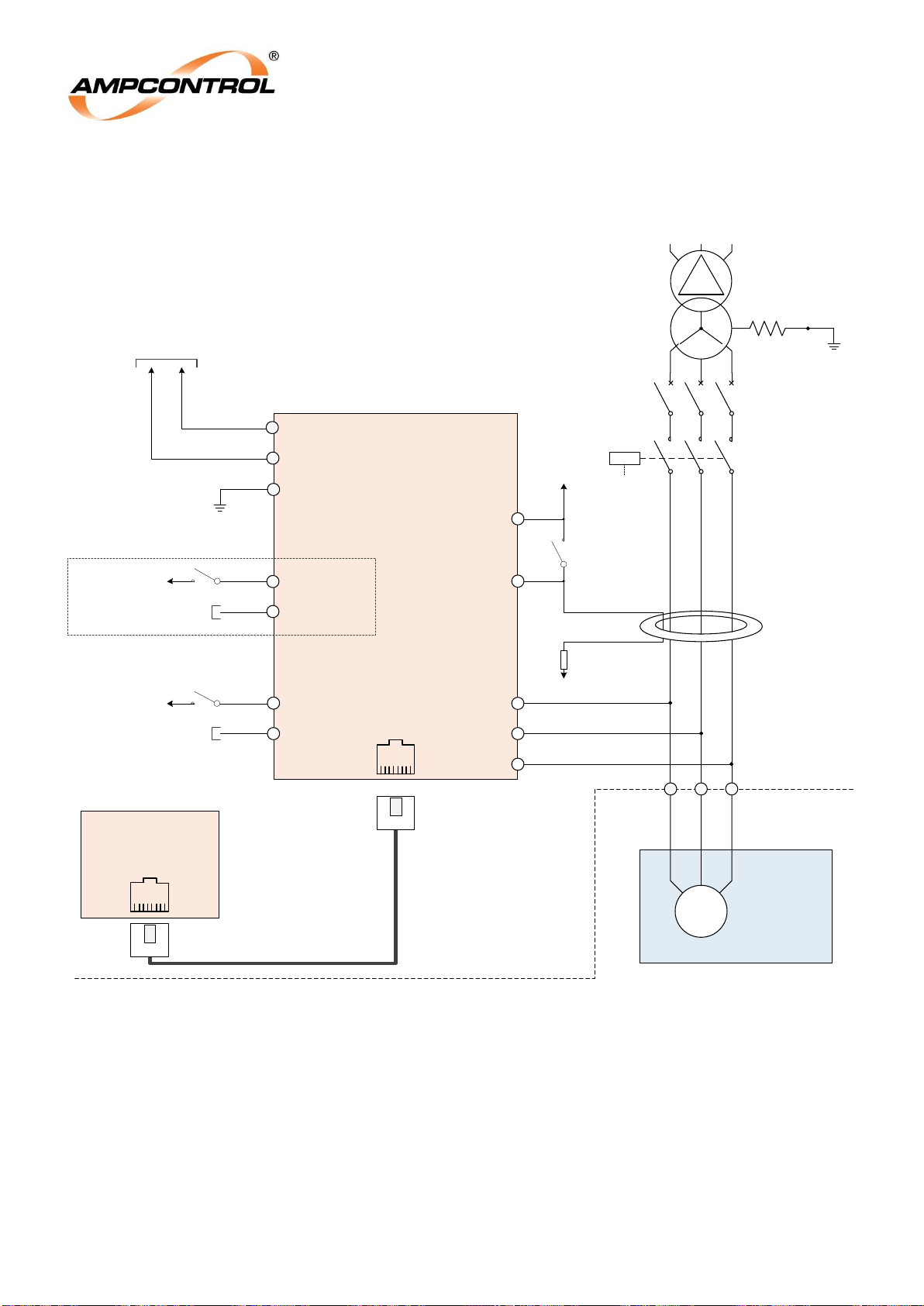
A typical installation diagram of the OTS-EL is shown below, Figure 4.6. The following sub-sections
provide a more detailed description of each of the individual circuit elements.
Figure 4.6: Electrical Connections - OTS-EL Circuit Diagram
MC
Main
Contactor
Circuit
Breaker
CBA
S2
11
12
OTS-EL
1
2
58
9
Ua
Ub
S1
Uc
MC AUX 110V N
110VAC Control
Supply
Straight through CAT5 OR
CAT6 cable
24VAC/VDC
Control Supply
MC AUX
MC AUX N
4
AC Test
Supply
EL TEST – N/O
Manual EL Test
Pushbutton
(If Present)
EL TEST – COM
MC AUX 110V A
MC AUX A
NER
Supply Enclosure
COMMS
MODULE
POWER 1
POWER 2
24V DC or AC
Power Supply
3
EARTH
Motor
Enclosure
M
Either the 110V or 24V auxiliary inputs
should be used – not both at the same time.
Note*:
MC AUX
0V
Control Supply
0VAC
Control Supply
Optional Connection*
Page 14
Ampcontrol Pty Ltd – ABN 28 000 915 542
OTS-EL USER MANUAL
MAG-205 Version 3 – DEC/19
Uncontrolled Copy - Refer to Ampcontrol Website for Latest Version
Page 14 of 23
APPROVED FOR EXTERNAL DISTRIBUTION
– PROPERTY OF AMPCONTROL PTY LTD
– NOT TO BE REPRODUCED IN PART
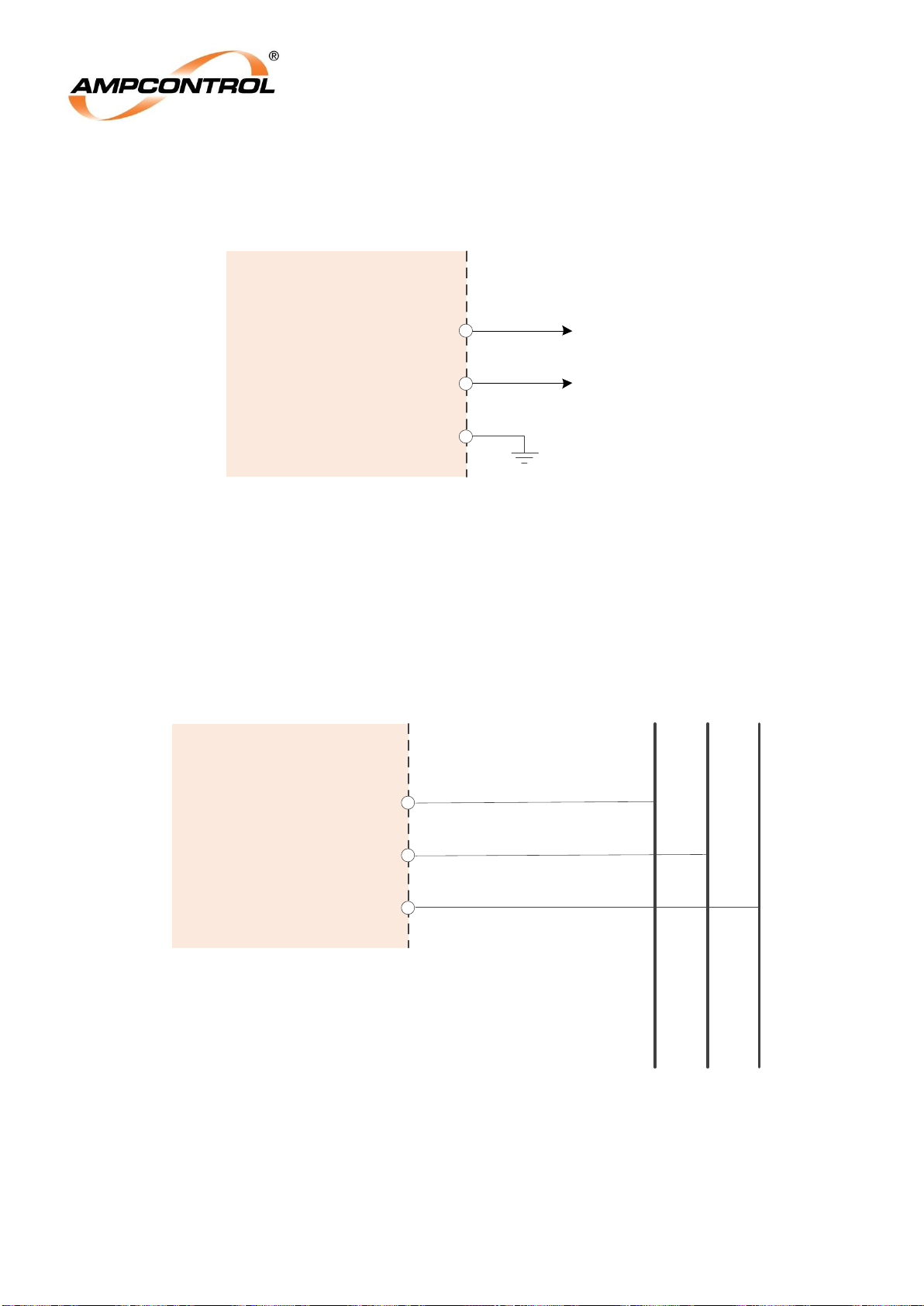
4.4.1 Power Supply (Terminals 1, 2 & 3)
The OTS-EL requires a regulated 24VDC or 24VAC power supply.
Figure 4.7: Electrical Connections – OTS-EL Power Supply
4.4.2 Line Connections (Terminals Ua, Ub & Uc)
The OTS-EL contains an internal high voltage barrier that allows the OTS-EL to directly interface with
the phase conductors.
The high voltage connections from the OTS-EL must be made on the load side of the outlet’s contactor
/ breaking device.
Figure 4.8: Electrical Connections: Internal HV Barrier
OTS - EL
01
Supply
Connections
03
POWER1
24VDC or 24VAC
Control Supply
02
POWER2
0VDC or 0VAC
Control Supply
EARTH
OTS - EL
Line
Connections
Phase
Conductors
Uc
Ua
Ub
Page 15
Ampcontrol Pty Ltd – ABN 28 000 915 542
OTS-EL USER MANUAL
MAG-205 Version 3 – DEC/19
Uncontrolled Copy - Refer to Ampcontrol Website for Latest Version
Page 15 of 23
APPROVED FOR EXTERNAL DISTRIBUTION
– PROPERTY OF AMPCONTROL PTY LTD
– NOT TO BE REPRODUCED IN PART
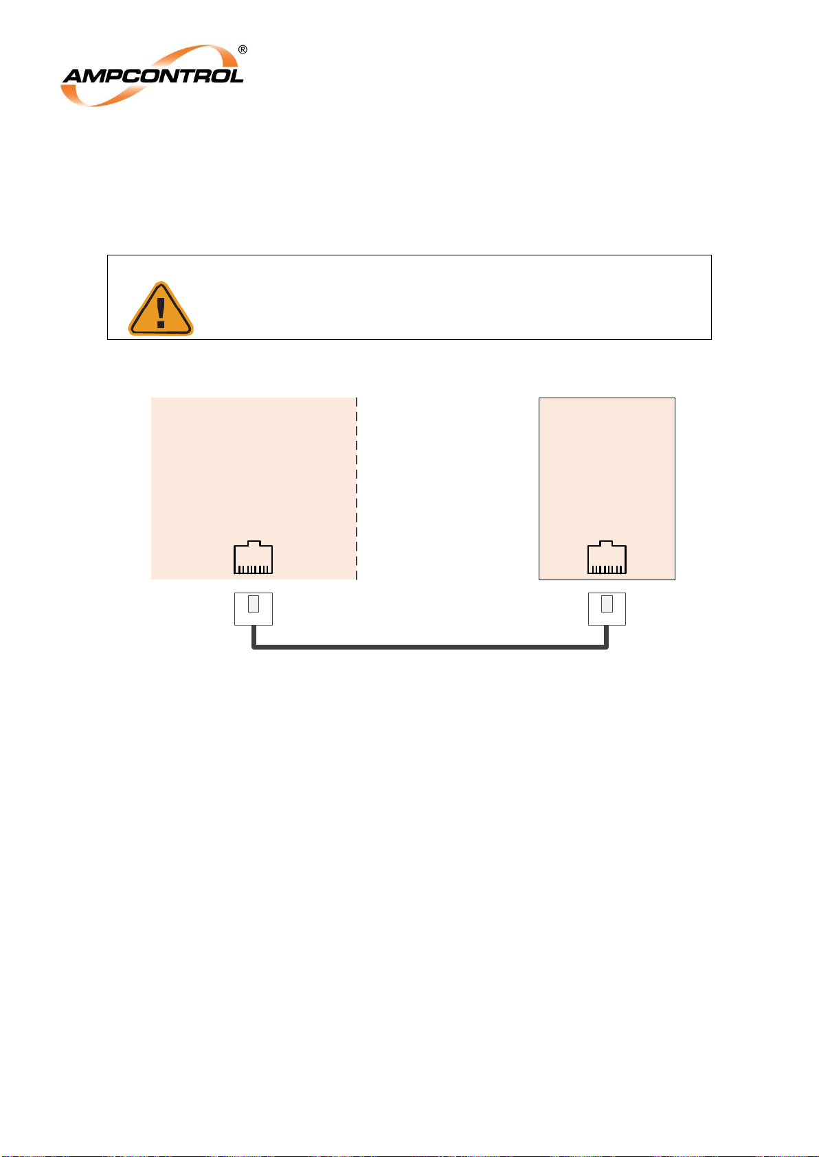
4.4.3 Comms Module Connections (RJ45 Port)
The OTS-EL interfaces with the user’s compatible tablet via the OTS Comms Module. The Comms
Module is connected to the OTS-EL via a standard CAT5 or CAT6 cable (straight-through RJ45
termination).
CAUTION!
This Comms Module Connection Ports are not standard Ethernet
ports. These cores carry voltages that will damage an incompatible
device if connected.
Figure 4.9: Electrical Connections: Comms Module
OTS - EL
Comms Module
Connection
COMMS
MODULE
“Straight Through”
CAT5 or CAT6 Cable
Page 16
Ampcontrol Pty Ltd – ABN 28 000 915 542
OTS-EL USER MANUAL
MAG-205 Version 3 – DEC/19
Uncontrolled Copy - Refer to Ampcontrol Website for Latest Version
Page 16 of 23
APPROVED FOR EXTERNAL DISTRIBUTION
– PROPERTY OF AMPCONTROL PTY LTD
– NOT TO BE REPRODUCED IN PART
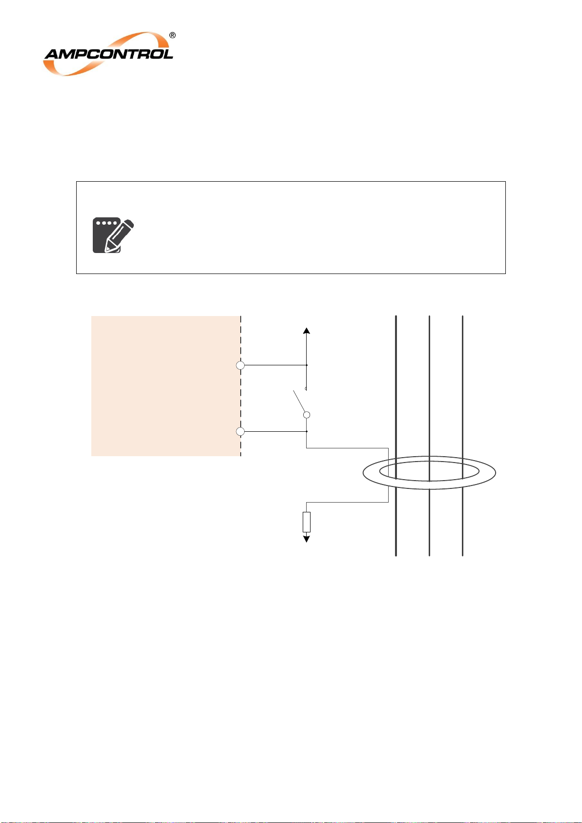
4.4.4 EL Test Connections (Terminals 4 & 5)
The Earth Leakage Test works by closing an internal normally open contact for the duration of the test.
This contact is intended to be wired in parallel to an existing earth leakage test circuit that passes an
AC current through the outlet’s earth leakage toroid.
NOTE
The installer is responsible for ensuring that the test resistance is of a
suitable magnitude to provide a meaningful test.
It is recommended that the resistance value is chosen such that the test
current is between 110% and 120% of the trip level of the earth leakage
protection relay (AS/NZS 2081 Appendix E4, AS/NZS 4871.1:2012
Clause 2.6.2.4).
Figure 4.10: Electrical Connections – EL Test
S1
S2
OTS - EL
04
Earth Leakage Test Connections
05
AC Test Supply
Manual EL Test
Pushbutton
(If Present)
EL TEST – 1
EL TEST – 2
Phase Conductors
AC Test Supply
Test Resistor
(120% of Trip Level)
Page 17
Ampcontrol Pty Ltd – ABN 28 000 915 542
OTS-EL USER MANUAL
MAG-205 Version 3 – DEC/19
Uncontrolled Copy - Refer to Ampcontrol Website for Latest Version
Page 17 of 23
APPROVED FOR EXTERNAL DISTRIBUTION
– PROPERTY OF AMPCONTROL PTY LTD
– NOT TO BE REPRODUCED IN PART
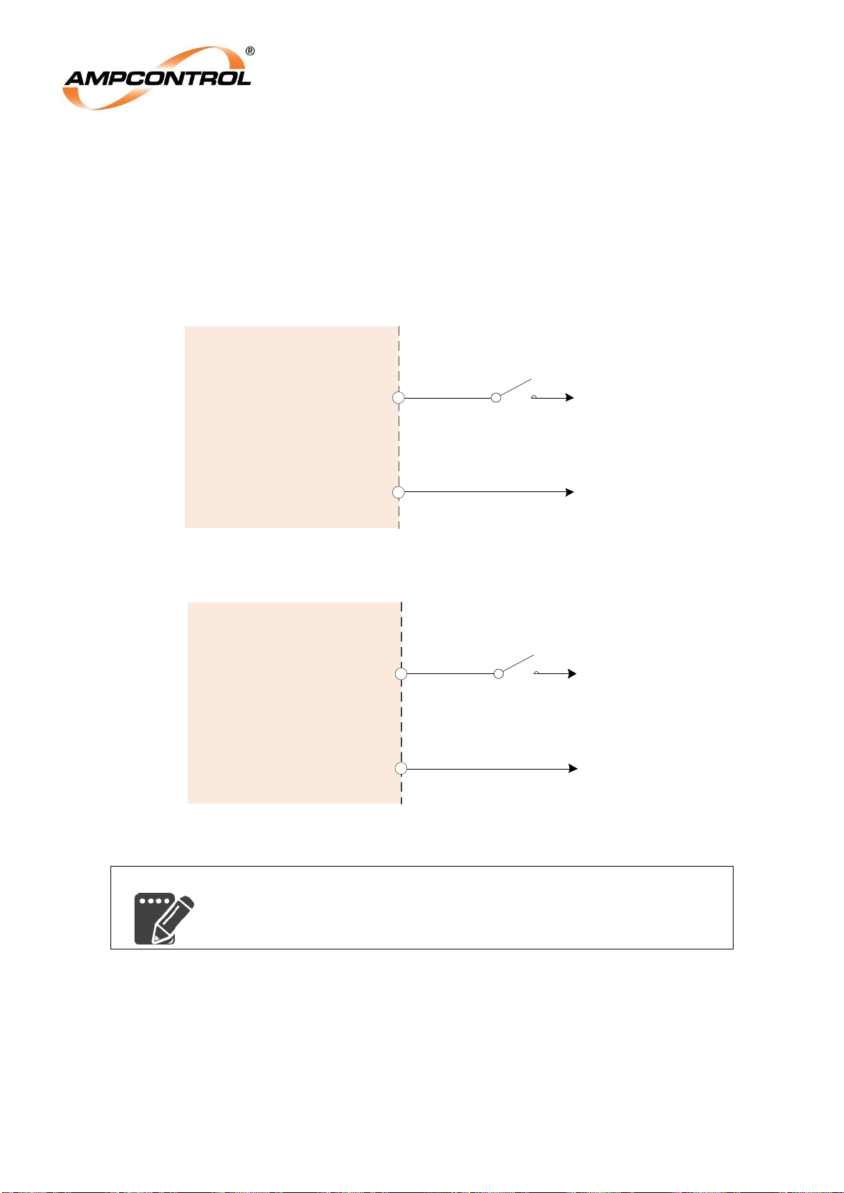
4.4.5 MC Auxiliary Input Connections (Terminals 8 & 9 or 11 & 12)
The MC Auxiliary Input provides feedback to the OTS-EL on the current position of the outlet’s
contactor / breaking device. The OTS-EL provides two options for monitoring the MC Auxiliary. The first
option is used in 110VAC control circuits, as shown in Figure 4.11. The second option is to use the MC
AUX 24V input, as shown in Figure 4.12. This input is used with 24VDC or 24VAC control supplies.
The MC AUX 110V and the MC AUX 24V input do not require a load to be present; the voltage input
can connect directly to the input (via the contactor’s auxiliary contact).
Figure 4.11: Electrical Connections – MC Auxiliary Input (Option 1)
Figure 4.12: Electrical Connections – MC Auxiliary Input (Option 2)
NOTE
Either the 110V or 24V auxiliary inputs should be used – not both at the
same time.
OTS - EL
08
09
MC AUX 110V A
MC AUX 110V N
MC Input Connections
(Option 1: 110VAC Control)
110VAC
Control Supply
0VAC
Control Supply
Auxiliary Contact
from Main Contactor
(or Breaking Device)
OTS - EL
11
MC AUX +
MC Input Connections
(Option 2: 24VAC/VDC Control)
12
MC AUX -
24VAC/VDC
Control Supply
Auxiliary Contact
from Main Contactor
(or Breaking Device)
0VAC
Control Supply
Page 18
Ampcontrol Pty Ltd – ABN 28 000 915 542
OTS-EL USER MANUAL
MAG-205 Version 3 – DEC/19
Uncontrolled Copy - Refer to Ampcontrol Website for Latest Version
Page 18 of 23
APPROVED FOR EXTERNAL DISTRIBUTION
– PROPERTY OF AMPCONTROL PTY LTD
– NOT TO BE REPRODUCED IN PART
5 PRODUCT OPERATION
All tests are initiated wirelessly through Bluetooth from the AmpINTEL PowerSAFE OTS software. The
AmpINTEL PowerSAFE OTS Application software is compatible with Android versions 4.3 and above.
As the OTS application has been developed and tested on the Samsung Galaxy Tab A with Android
version 6.0.1, Ampcontrol can only guarantee compatibility with this device.
CAUTION!
Ampcontrol cannot guarantee correct operation of the AmpINTEL
PowerSAFE OTS application if a non-compatible smart device is
utilised.
During a test, the results will be displayed on the tablet and a report will be generated upon completion.
These test reports are stored on the tablet until the tablet gains network access. At this point the test
reports are uploaded to the dashboard, a site specific cloud based storage platform.
Once these reports have been uploaded, all reports except for the most recent will be removed from the
tablet. The most recent report is saved on the tablet because, at the beginning of each new connection,
the OTS-EL will check to make sure there are no discrepancies between the results obtained from the
last test and those stored on the tablet. If there are any differences the test report will be updated to
those stored in the OTS-EL. If the reports are different (i.e. the last test was conducted on a different
device) a new test report will be generated with the data stored on the OTS-EL. This is of particular use if
there were any issues with the tablet or Bluetooth connection during testing.
For more information on the operation on the OTS-EL Android Application or the Dashboard please refer
to the relevant user manual.
NOTE
The Bluetooth range is limited to a maximum of approximately three
metres (3m). This distance is an advised maximum, various factors
will influence the connection distance.
Page 19

Ampcontrol Pty Ltd – ABN 28 000 915 542
OTS-EL USER MANUAL
MAG-205 Version 3 – DEC/19
Uncontrolled Copy - Refer to Ampcontrol Website for Latest Version
Page 19 of 23
APPROVED FOR EXTERNAL DISTRIBUTION
– PROPERTY OF AMPCONTROL PTY LTD
– NOT TO BE REPRODUCED IN PART
5.1 Earth Leakage Protection Function Test
The Earth Leakage test can only be initiated with the outlet energised. When the EL test is initialised, the
OTS-EL will energise the existing external EL test circuit. This simulates an EL current to be detected by
the outlet’s earth leakage toroid.
NOTE
The OTS itself does not generate the test current; it operates in parallel
to the existing manual EL test circuit.
Once the earth leakage test is initiated, the OTS-EL will measure the time taken for the outlet to open its
contactor or breaking device. In addition, the OTS-EL will also monitor the voltage on the load side of
this breaking device to determine the time that it takes for the back EMF generated by the connected
load to subside to extra low voltage (<50VAC). This represents the true clearing time following an earth
leakage fault.
The magnitude of the current that flows through the earth leakage toroid is determined by the design of
the test circuit installed. It is the responsibility of the installer to ensure that this current is sized to provide
meaningful results when the earth leakage test is conducted by the OTS.
NOTE
The installer is responsible for ensuring that the EL test current is of a
suitable magnitude to provide a meaningful test.
It is recommended that the circuit design is chosen such that the test
current is between 110% and 120% of the trip level of the earth leakage
protection relay (AS/NZS 2081 Appendix E4, AS/NZS 4871.1:2012
Clause 2.6.2.4).
Page 20
Ampcontrol Pty Ltd – ABN 28 000 915 542
OTS-EL USER MANUAL
MAG-205 Version 3 – DEC/19
Uncontrolled Copy - Refer to Ampcontrol Website for Latest Version
Page 20 of 23
APPROVED FOR EXTERNAL DISTRIBUTION
– PROPERTY OF AMPCONTROL PTY LTD
– NOT TO BE REPRODUCED IN PART
6 OPERATIONAL INTERFACE
This section will give an explanation of the physical location and the operational characteristics of the
OTS-EL’s interface elements.
6.1 OTS-EL Operational Interface
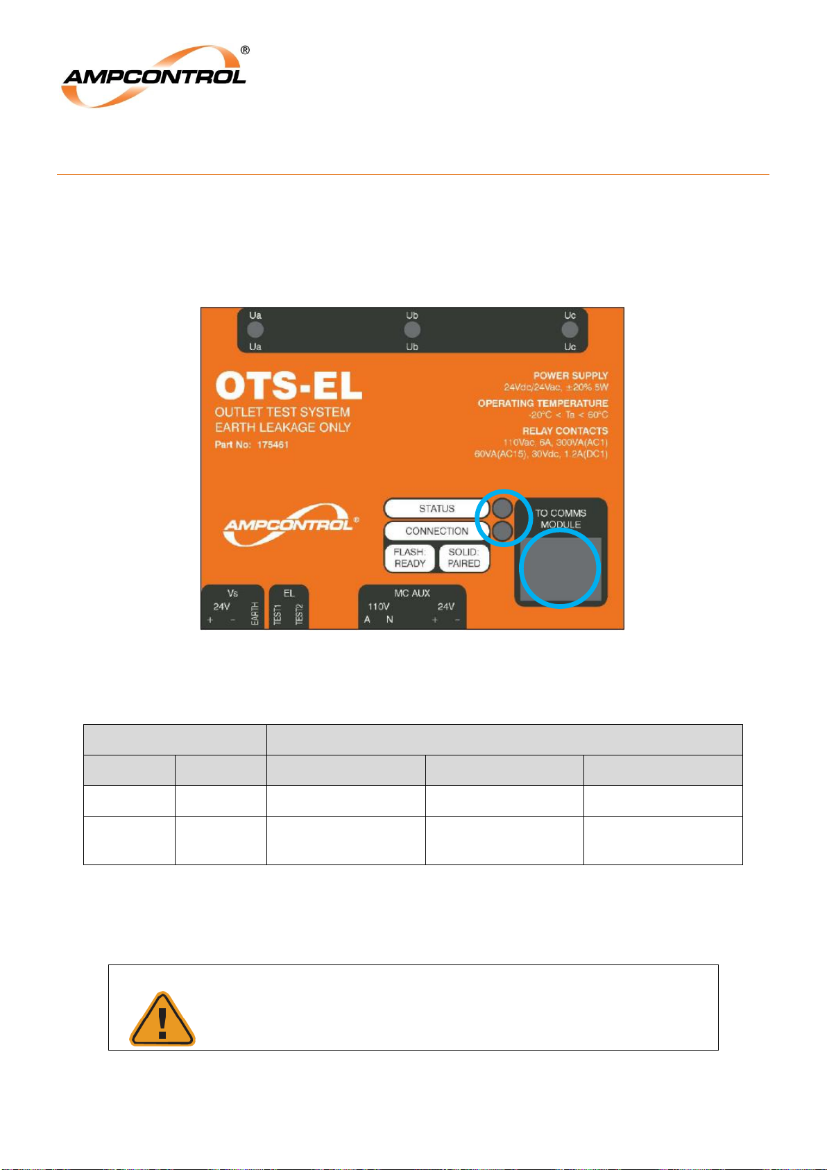
The OTS-EL has two LEDs and a RJ45 connection port (identified in Figure 6.1). The operation of the
LED’s is detailed in Table 2.
Figure 6.1: OTS-EL Operational Interface
Table 2: OTS-EL Fascia LED Operation
LED
Behaviour
Name
Colour
Off
Flashing
On
Status
Green
Control Power Off
Healthy
Processor Error
Comms
Blue
Not Connected to
Comms Module
Ready for
Connection to Tablet
Connected to the
Tablet
The RJ45 port is designed to connect the OTS-EL to the Comms Module via a straight through CAT5 or
CAT6 cable.
CAUTION!
The Comms Module Connection Ports are not standard Ethernet
ports. These cores carry voltages that will damage an incompatible
device if connected.
Page 21
Ampcontrol Pty Ltd – ABN 28 000 915 542
OTS-EL USER MANUAL
MAG-205 Version 3 – DEC/19
Uncontrolled Copy - Refer to Ampcontrol Website for Latest Version
Page 21 of 23
APPROVED FOR EXTERNAL DISTRIBUTION
– PROPERTY OF AMPCONTROL PTY LTD
– NOT TO BE REPRODUCED IN PART
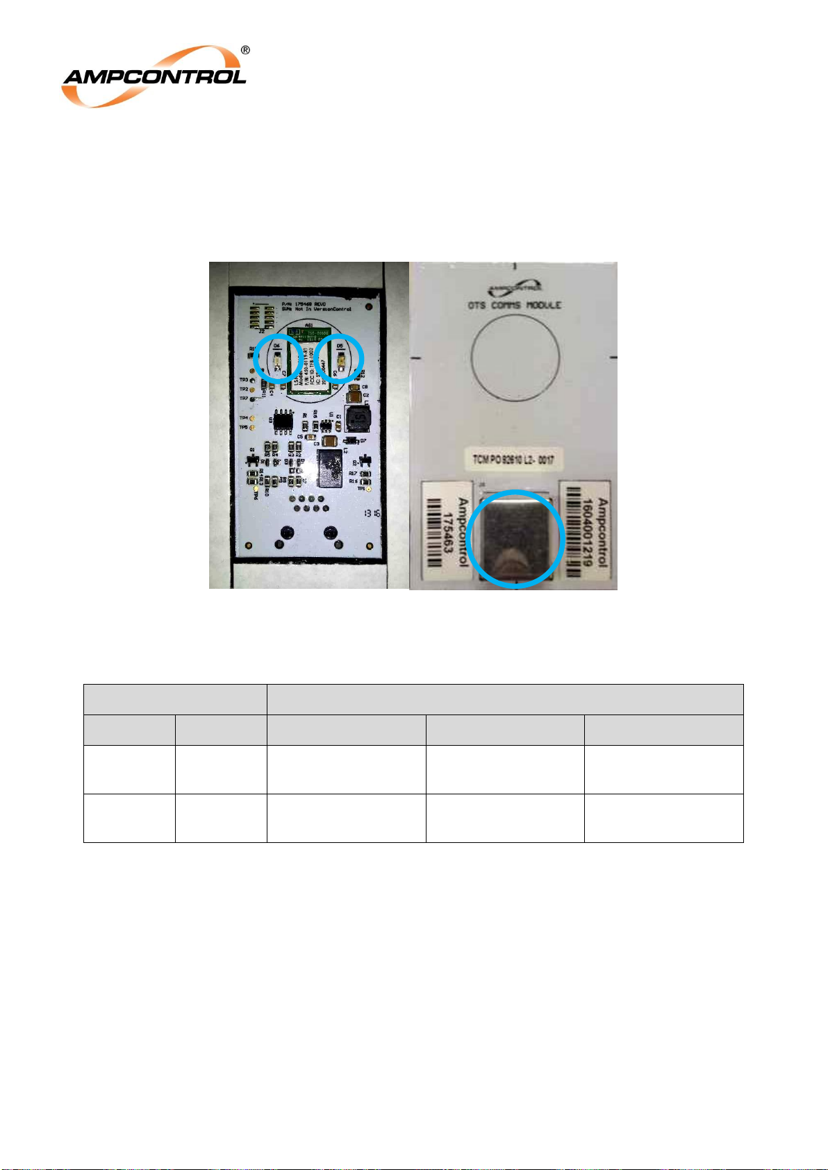
6.2 OTS Comms Module Operational Interface
If the OTS Comms Module is installed correctly, the two LEDs identified on the left in Figure 6.2, will line
up with the label that is installed over the hole on the outside of the enclosure. These LEDs are the
Paired LED (left) and the Testing LED (right). The operation of the LEDs is detailed in Table 3.
Figure 6.2: Comms Module Operational Interface
Table 3: OTS-EL Comms Module LED Operation
LED
Behaviour
Name
Colour
Off
Flashing
On
Paired
Blue
Not Connected to
OTS-EL
Ready for
Connection to Tablet
Connected to the
Tablet
Testing
Red
No Testing in
Progress
Testing in Progress
Testing Completed
Page 22

Ampcontrol Pty Ltd – ABN 28 000 915 542
OTS-EL USER MANUAL
MAG-205 Version 3 – DEC/19
Uncontrolled Copy - Refer to Ampcontrol Website for Latest Version
Page 22 of 23
APPROVED FOR EXTERNAL DISTRIBUTION
– PROPERTY OF AMPCONTROL PTY LTD
– NOT TO BE REPRODUCED IN PART
7 SERVICE, MAINTENANCE & DISPOSAL
7.1 Equipment Service
A number of external system based checks should be completed on a regular basis. These ‘routine
inspections’ must be carried out by suitably trained people with knowledge of the Outlet Test System and
the systems into which it is fitted. Routine inspections may take the form of either visual-only checks, or
visual and ‘hands-on’ checks.
7.1.1 Visual Only Inspections
A basic visual inspection focuses on looking at the installation for signs of physical damage, water or
dust ingress and the condition of cables and labels. This type of inspection may involve opening
cabinets to gain access to the OTS-EL and other equipment. This level of inspection may also include
cleaning display windows that have become obscured by dirt.
Observations would typically be:
Check that equipment enclosures, cable trays, conduits, etc. are in good order with no physical
damage.
Check that sealed wall boxes are free from water and dust ingress internally. Door seals are in
good condition.
Check that connected cables are free from cuts, abrasions and obvious signs of damage. Cable
restraints are in good order and correctly fitted.
Check that labels on equipment, wall boxes and cables are present and in good condition
(especially certification labels).
Check that no modifications have been carried out to installed equipment.
7.1.2 Hands-On (Detailed) Inspections
A more detailed inspection would include all of the elements of a visual inspection, plus some checks
that cover the integrity of connections, fixtures and fittings.
In addition to basic visual observations, more detailed integrity checks would involve:
Verify that equipment housings, wall boxes and other mechanical fixtures are secured in place.
This includes terminal box lids, tightness of cable glands, integrity of wall-box mountings, security
of equipment fixing to walls/DIN rails etc.
Verify all electrical connections are secure with no loose screw terminals or DIN rail terminals not
fitted to rails etc.
7.2 Equipment Maintenance
WARNING!
The OTS-EL has no user-serviceable parts.
All repairs must be carried out by Ampcontrol only.
If a fault develops, return the unit to Ampcontrol for repair. It is essential
that no attempt be made to repair the unit as any attempt to
dismantle or repair the unit can seriously compromise the safety of
the unit and voids product warranty.
Page 23

Ampcontrol Pty Ltd – ABN 28 000 915 542
OTS-EL USER MANUAL
MAG-205 Version 3 – DEC/19
Uncontrolled Copy - Refer to Ampcontrol Website for Latest Version
Page 23 of 23
APPROVED FOR EXTERNAL DISTRIBUTION
– PROPERTY OF AMPCONTROL PTY LTD
– NOT TO BE REPRODUCED IN PART
7.3 Disposal
ENVIRO
The electronic equipment discussed in this manual must not be
treated as general waste. By ensuring that this product is disposed of
correctly you will be helping to prevent potentially negative
consequences for the environment which could otherwise be caused by
incorrect waste handling of this product.
8 SPECIFICATIONS
Specifications
Supply
Regulated Voltage
24V DC or 24V AC (50Hz) ±20%
Power Supply Requirement
5VA
Dimensions
OTS-EL (mm)
91 x 100 x 110
Comms Module (mm)
86 x 54 x 21
Earth Leakage Test
Test Interface
Current injected through the earth leakage toroid
Measured Entities
Elapsed time between trip initiation and outlet contactor opening and,
Elapsed time between trip initiation and the back EMF falling below ELV (true
clearing time).
Find Out More
For more information on this product, contact Ampcontrol Customer Service on +61 1300 267 373 or
[email protected] or visit the Ampcontrol website: www.ampcontrolgroup.com
9 EQUIPMENT LIST
Part Number
Description
175461
MODULE OTS TESTER
179019
MODULE OTS2 TESTER
175463
MODULE OTS COMMS
176536
MODULE OTS EL-ONLY TESTER
180264
MODULE OTS EL-ONLY TESTER Version 2
175462
MODULE OTS EXTERNAL EL/EC BARRIER
176852
OTS TESTERS TABLET 8” (LTE) C/W SOFTWARE AND CASE
177451
OTS TESTERS TABLET 8” (NON-LTE) C/W SOFTWARE AND CASE
 Loading...