

Page 1
Version: 2 – July 2017
Designed and Manufactured in Australia by Ampcontrol Pty Ltd
Integrated Monitoring and Control System
iMAC2 Controller EtherNet/IP Communications Manual
Page 2
Ampcontrol Pty Ltd – ABN 28 000 915 542
iMAC2 Controller EtherNet/IP Communications Manual
IMAC2B015 V2 – 07/17
APPROVED FOR EXTERNAL DISTRIBUTION – PROPERTY OF AMPCONTROL PTY LTD – NOT TO BE REPRODUCED IN PART
WARNING!
The warning symbol highlights a potential risk of injury or death.
Please share these warnings with other operators.
CAUTION!
The caution symbol highlights a potential risk of damage to
equipment.
Please share these cautions with other operators.
NOTE
The note symbol highlights key information.
Please share these notes with other operators.
ENVIRO
The enviro (environmental) symbol highlights areas which may have an
impact on the surrounding fauna and/or flora.
IMAC2B015 V2 Uncontrolled Copy - Refer to Ampcontrol Website for Latest Version Page 1 of 41
Page 3
Ampcontrol Pty Ltd – ABN 28 000 915 542
iMAC2 Controller EtherNet/IP Communications Manual
IMAC2B015 V2 – 07/17
APPROVED FOR EXTERNAL DISTRIBUTION – PROPERTY OF AMPCONTROL PTY LTD – NOT TO BE REPRODUCED IN PART
WARNING!
In the interests of safety and correct equipment operation, please
take the time to read and understand the content in this manual.
Copyright Notice
The Ampcontrol iMAC2 Integrated Monitoring and Control system described in this document is the property
of AMPCONTROL PTY LTD. It is furnished under a license agreement and is to be used only in accordance
with the terms of the agreement.
No part of the hardware or documentation may be reproduced, transmitted, transcribed, stored in a retrieval
system, or translated into any language or computer language, in any form or by any means, without prior
written permission of AMPCONTROL PTY LTD.
The iMAC signalling technique is protected by patent.
Disclaimer
While every effort has been made to assure the accuracy and clarity of this document, AMPCONTROL PTY
LTD assumes no liability resulting from any omissions in this document, or from misuse of the information
obtained herein. The information in this document has been carefully checked and is believed to be entirely
reliable with all of the necessary information included. AMPCONTROL PTY LTD reserves the right to make
changes to any products described herein to improve reliability, function, or design, and reserves the right to
revise this document and make changes from time to time in content hereof with no obligation to notify any
persons of revisions or changes. AMPCONTROL PTY LTD does not assume any liability arising out of the
application or any use of any product or circuit described herein; neither does it convey license under its
patent rights or the rights of others.
Before You Begin
Thank you for purchasing the Ampcontrol iMAC2 System.
Ampcontrol Contact Details
7 Billbrooke Close, Cameron Park, NSW, 2285
P +61 1300 267 373 | F +61 2 4903 4888
EMAIL: [email protected]
WEB: ampcontrolgroup.com
IMAC2B015 V2 Uncontrolled Copy - Refer to Ampcontrol Website for Latest Version Page 2 of 41
Page 4

Ampcontrol Pty Ltd – ABN 28 000 915 542
iMAC2 Controller EtherNet/IP Communications Manual
IMAC2B015 V2 – 07/17
APPROVED FOR EXTERNAL DISTRIBUTION – PROPERTY OF AMPCONTROL PTY LTD – NOT TO BE REPRODUCED IN PART
TABLE OF CONTENTS
DOCUMENT SCOPE ................................................................................................. 5 1
Document Scope .............................................................................................. 5 1.1
Supplementary Documents .............................................................................. 5 1.2
1.2.1 System Documentation ........................................................................... 5
1.2.2 Module Documentation ................................................................ ........... 5
iMAC2 CONTROLLER ETHERNET/IP COMMUNICATIONS OVERVIEW ................. 6 2
Specifications ................................................................................................... 6
2.1
Connecting to the Ethernet Port for the First Time ............................................ 7 2.2
EtherNet/IP Protocol ....................................................................................... 10 2.3
THE iMAC2 CONTROLLER’S DATA TRANSFER .................................................... 11 3
Input Assembly Instance Layout ..................................................................... 11 3.1
Module Types ................................................................................................. 13 3.2
DATA HANDLING – RSLogix5000 APPLICATIONS ................................................ 15 4
UDTs .............................................................................................................. 15 4.1
4.1.1 iMac_SystemStatus_DT ....................................................................... 15
4.1.2 iMac_SystemControl_DT ...................................................................... 16
4.1.3 iMac_Ctrl_Runtime_DT ......................................................................... 17
4.1.4 iMac_Ctrl_LCD_DT ............................................................................... 18
4.1.5 iMac_Controller_DT .............................................................................. 18
4.1.6 iMac_Network_Config_Entry_DT .......................................................... 19
4.1.7 iMac_Network_Config_DT .................................................................... 20
4.1.8 iMac_STATUS_DT ............................................................................... 20
4.1.9 iMac_ERROR_DT ................................................................................ 21
4.1.10 iMac_AIM_AI_ModDT ......................................................................... 21
4.1.11 iMac_AIM_FLAGS_ModDT ................................................................. 22
4.1.12 iMac_AIM_Power_ModDT .................................................................. 22
4.1.13 iMac_DI4_ModDT ............................................................................... 23
4.1.14 iMac_DI8_ModDT ............................................................................... 23
4.1.15 iMac_GAI3_FLAGS_ModDT ............................................................... 24
4.1.16 iMac_GAI3_AI_ModDT ....................................................................... 25
4.1.17 iMac_IIM_ModDT ............................................................................... 25
4.1.18 iMac_LED4_ModDT............................................................................ 26
4.1.19 iMac_RIS_ModDT .............................................................................. 26
IMAC2B015 V2 Uncontrolled Copy - Refer to Ampcontrol Website for Latest Version Page 3 of 41
Page 5

Ampcontrol Pty Ltd – ABN 28 000 915 542
iMAC2 Controller EtherNet/IP Communications Manual
IMAC2B015 V2 – 07/17
APPROVED FOR EXTERNAL DISTRIBUTION – PROPERTY OF AMPCONTROL PTY LTD – NOT TO BE REPRODUCED IN PART
4.1.20 iMac_RO4_ModDT ............................................................................. 27
4.1.21 iMac_RTD1_FLAGS_ModDT .............................................................. 27
4.1.22 iMac_RTD_Temp_ModDT .................................................................. 28
4.1.23 iMac_RTD3_FLAGS_ModDT .............................................................. 28
4.1.24 iMac_SIM_G_ModDT ......................................................................... 29
4.1.25 iMac_SIM_G2_ModDT ....................................................................... 29
4.1.26 iMac_SIM_P_ModDT .......................................................................... 30
4.1.27 iMac_SIM_T_ModDT .......................................................................... 30
4.1.28 iMac_SSW_Control_ModDT ............................................................... 31
4.1.29 iMac_SSW_FLAGS_ModDT ............................................................... 32
4.1.30 iMac_SSW_Value_ModDT ................................................................. 33
4.1.31 iMac_Modules_DT .............................................................................. 34
AOIs ............................................................................................................... 36 4.2
4.2.1 iMac_Demux_AOI ................................................................................. 36
4.2.2 iMac_Clear_Data_AOI .......................................................................... 36
4.2.3 iMac_Errors_Assign_AOI ...................................................................... 37
4.2.4 iMac_Status_Assign_AOI ..................................................................... 37
RSLogix5000 Program/Routine Usage ........................................................... 37 4.3
Example Setup ............................................................................................... 39 4.4
TABLE OF FIGURES
Figure 1: Location of the Ethernet Communications Port ..................................................... 6
Figure 2: Location of Ethernet Reset Switch ........................................................................ 7
Figure 3: Updating the Ethernet Port Settings of the Connectable Device ............................ 8
Figure 4: Updating the iMAC2 Controller Ethernet Port Settings .......................................... 9
Figure 5: Minimum Program/Routine requirements for getting iMAC2 EtherNet/IP data in
RSLogix5000 ..................................................................................................................... 38
Figure 6: Generic Ethernet Module setup for iMAC2 EIP data. .......................................... 38
Figure 7: iMAC2 Demonstration Box .................................................................................. 39
Figure 8: iMAC web interface online modules. ................................................................... 40
Figure 9: Node 30 data transferred to the PLC. .................................................................. 41
IMAC2B015 V2 Uncontrolled Copy - Refer to Ampcontrol Website for Latest Version Page 4 of 41
Page 6

Ampcontrol Pty Ltd – ABN 28 000 915 542
iMAC2 Controller EtherNet/IP Communications Manual
IMAC2B015 V2 – 07/17
APPROVED FOR EXTERNAL DISTRIBUTION – PROPERTY OF AMPCONTROL PTY LTD – NOT TO BE REPRODUCED IN PART
DOCUMENT SCOPE 1
Document Scope 1.1
This document is intended to provide a detailed explanation of the communications protocols supported by
the iMAC2 Controller’s Ethernet port.
This document is not intended to provide information on the operation of the overall iMAC System, individual
modules or instruction on programming the iMAC2 Controller or modules. Please refer to the relevant
supplementary documents for this information.
Supplementary Documents 1.2
The iMAC2 Controller Ethernet/IP Communications Manual is intended to be read in conjunction with the
following documents:
1.2.1 System Documentation
IMAC2B010 iMAC2 Controller Ethernet Communications Manual
IMAC2B009 iMAC2 System User Manual
IMAC2B011 iMAC2 Controller Web Interface Manual
IMACB094 iMAC System Installation Requirements
IMACB155 iMAC SIL Emergency Stop Qualification
IMACB005 iMAC Module Programming Manual
1.2.2 Module Documentation
IMACB003 iMAC RO4 Module Technical Datasheet
IMACB018 iMAC LPU Module Technical Datasheet
IMACB020 iMAC DI8 Module Technical Datasheet
IMACB045 iMAC IIM Module Technical Datasheet
IMACB046 iMAC DI4 Module Technical Datasheet
IMACB047 iMAC EOL/MEOL Module Technical Datasheet
IMACB060 iMAC LED4 Module Technical Datasheet
IMACB061 iMAC SSW Module Technical Datasheet
IMACB062 iMAC SQM Module Technical Datasheet
IMACB066 iMAC AIM Module Technical Datasheet
IMACB067 iMAC RTD1 Module Technical Datasheet
IMACB141 iMAC ARM Module Technical Datasheet
IMACB142 iMAC CRM Module Technical Datasheet
IMACB143 iMAC EMM Module Technical Datasheet
IMACB144 iMAC GRM Module Technical Datasheet
IMACB146 iMAC IRK Keypad Technical Datasheet
IMACB147 iMAC PIM Module Technical Datasheet
IMACB148 iMAC SIM-G Module Technical Datasheet
IMACB149 iMAC SIM-G2 Module Technical Datasheet
IMACB150 iMAC SIM-T Module Technical Datasheet
IMACB151 iMAC MLB Barrier Technical Datasheet
IMACB152 iMAC SLB Barrier Technical Datasheet
IMACB154 iMAC SIM-P Module Technical Datasheet
IMAC2B015 V2 Uncontrolled Copy - Refer to Ampcontrol Website for Latest Version Page 5 of 41
Page 7
Ampcontrol Pty Ltd – ABN 28 000 915 542
iMAC2 Controller EtherNet/IP Communications Manual
IMAC2B015 V2 – 07/17
APPROVED FOR EXTERNAL DISTRIBUTION – PROPERTY OF AMPCONTROL PTY LTD – NOT TO BE REPRODUCED IN PART
NOTE
The Ethernet port is a read only communications port. The iMAC2
Controller has been manufactured in this way to maintain the SIL
“Proven in Use” statistics of the previous iMAC Controller.
Ethernet TCP/IP Port
Available Interfaces
RJ45 10/100MB, Auto Negotiation
Applicable Standards
IEEE 802.3u, IEEE 802.3x
Cable Requirements
10BASE-T: UTP category 3, 4, 5 cable (maximum 100m)
100BASE-TX: UTP category 5, 5e cable (maximum 100m)
EIA/TIA-568 100Ω STP (maximum 100m)
Supported Protocols
EtherNet/IP (Port 2222), NTP (for time synchronisation), Webserver (for
configuration, data viewing and diagnostic functions)
Maximum Request Rate
400ms
Recommended Response
Timeout
200ms
Maximum Concurrent
Web Connections
The iMAC2 Controller allows four users to access the web server.
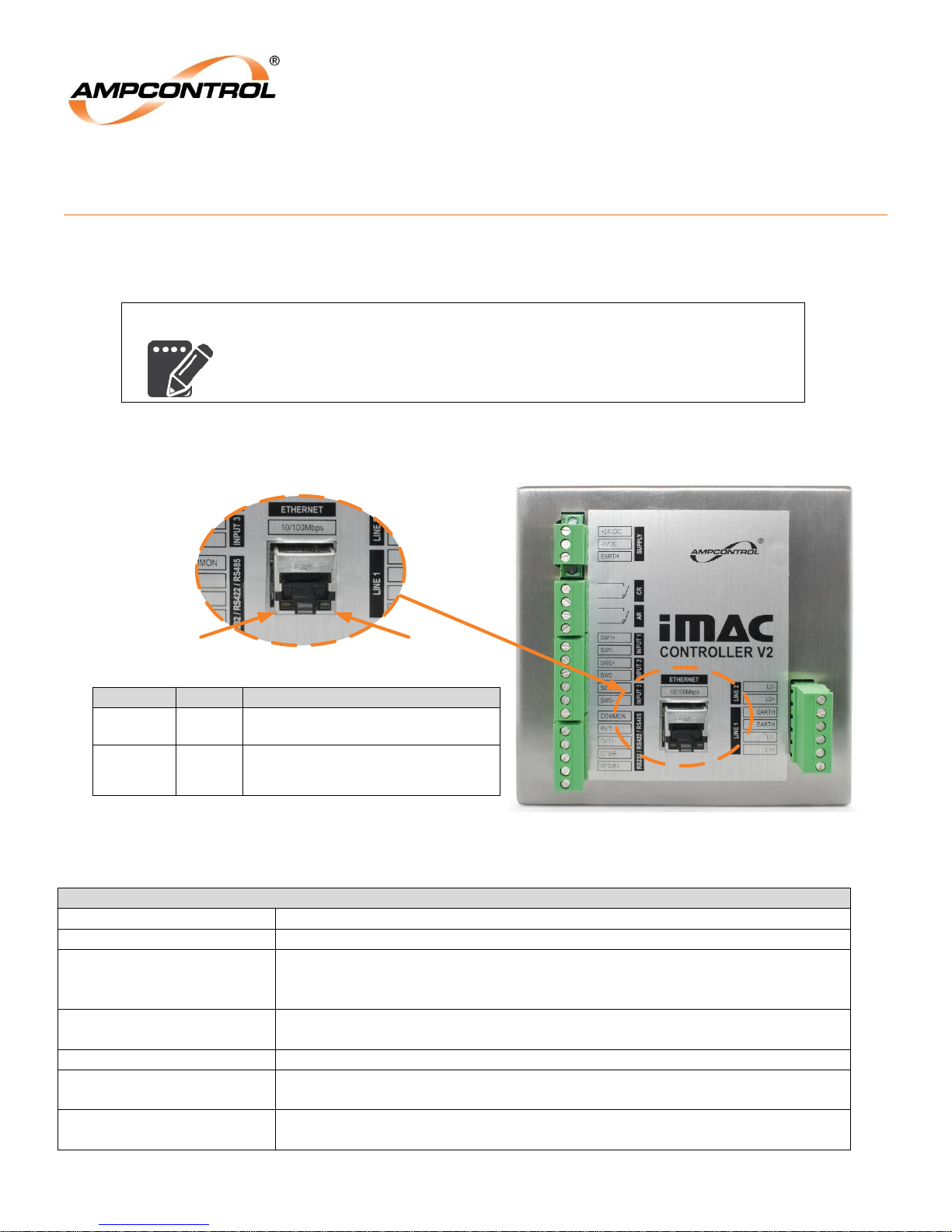
Ethernet Communications Port
Name
Link Activity
Link Speed
Operation
On when valid link is detected. Blinks when
activity is detected.
On when operating speed is 100Mbps. Off
when the line speed is 10Mbps, or during line
isolation.
Link Activity LED
(Yellow)
Link Speed LED
(Green)
Colour
Yellow
Green
iMAC2 CONTROLLER ETHERNET/IP COMMUNICATIONS 2
OVERVIEW
The iMAC2 Controller is equipped with an Ethernet port and a serial communication port. This manual
details the use of the Ethernet port. For information pertaining to the use of the serial communications
port, refer to the IMACB153 iMAC Controller Serial Communications Manual.
Specifications 2.1
Figure 1: Location of the Ethernet Communications Port
Table 1: Ethernet Communications Port Specifications
IMAC2B015 V2 Uncontrolled Copy - Refer to Ampcontrol Website for Latest Version Page 6 of 41
Page 8
Ampcontrol Pty Ltd – ABN 28 000 915 542
iMAC2 Controller EtherNet/IP Communications Manual
IMAC2B015 V2 – 07/17
APPROVED FOR EXTERNAL DISTRIBUTION – PROPERTY OF AMPCONTROL PTY LTD – NOT TO BE REPRODUCED IN PART
Default Ethernet IPv4 Settings
IP Address
10.1.1.10
Subnet Mask
255.255.255.0
Ethernet Reset
Switch
Connecting to the Ethernet Port for the First Time 2.2
The iMAC2 Controller’s factory default Ethernet IPv4 settings are as follows:
Table 2: Default Ethernet Communications Port Settings
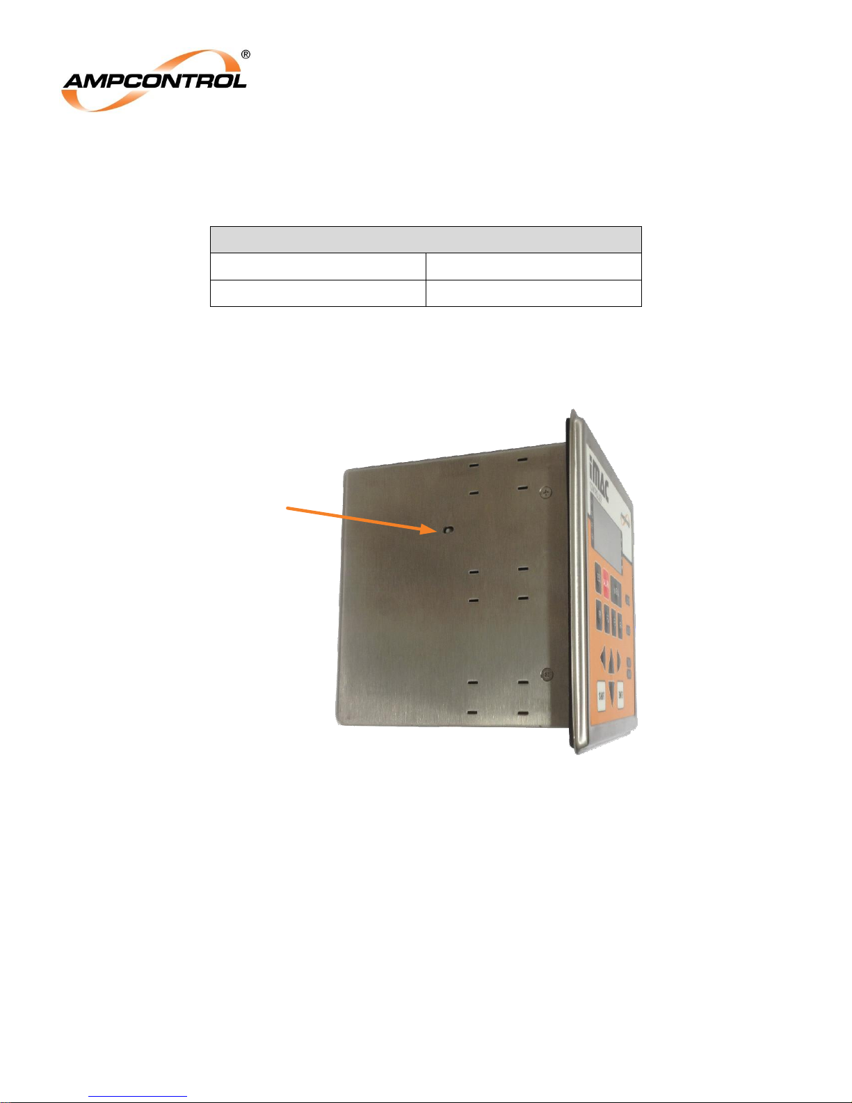
If the Controller’s IPv4 settings have been changed, they can be restored to the factory default settings by
pressing the iMAC2 Controller’s Ethernet Reset button for 4 seconds (The internal iMAC2 Controller status
LED will turn on solid while the reset button is depressed, after 4 seconds the LED will change to a fast flash
to indicate settings have been reset to default, after which the button can then be released).
Figure 2: Location of Ethernet Reset Switch
IMAC2B015 V2 Uncontrolled Copy - Refer to Ampcontrol Website for Latest Version Page 7 of 41
Page 9
Ampcontrol Pty Ltd – ABN 28 000 915 542
iMAC2 Controller EtherNet/IP Communications Manual
IMAC2B015 V2 – 07/17
APPROVED FOR EXTERNAL DISTRIBUTION – PROPERTY OF AMPCONTROL PTY LTD – NOT TO BE REPRODUCED IN PART
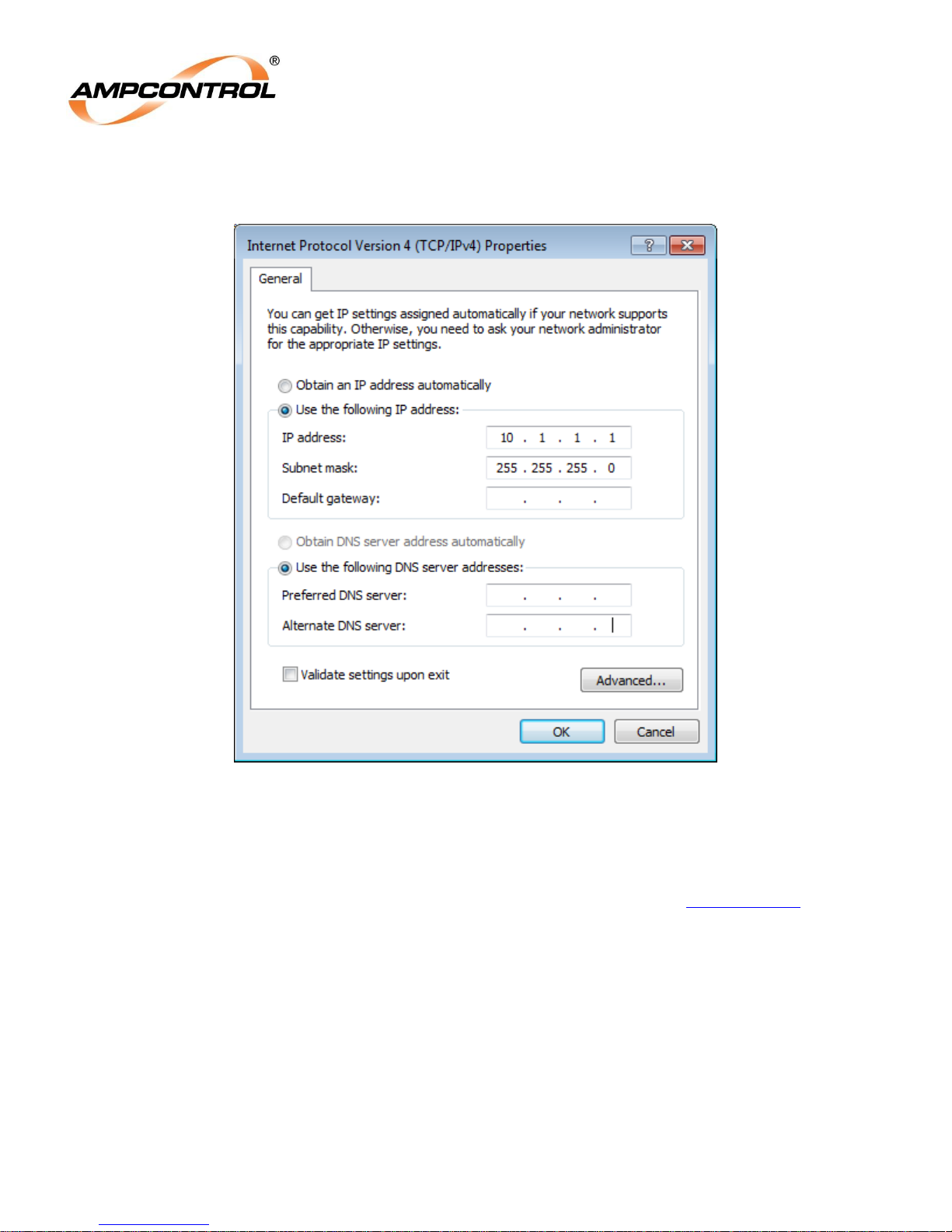
The iMAC2 Controller’s Ethernet port settings are not configurable via the HMI; they must be altered using
the iMAC2 Web Interface. The Controller’s web server can be accessed using a one-to-one Ethernet
connection with an Ethernet enabled device. Temporarily configure your device’s Ethernet port as follows:
Figure 3: Updating the Ethernet Port Settings of the Connectable Device
Once the network adaptor of the external device has been configured as shown in Figure 3, connect the
iMAC2 Controller’s Ethernet port directly to your device’s Ethernet port, the iMAC2 Controller should then be
able to be pinged at 10.1.1.10. Once a successful ping has been performed, open a web browser (Chrome
recommended) and enter the iMAC2 Controller’s IP address into the address bar: http://10.1.1.10; the
iMAC2 Controller web pages should load within a few seconds.
IMAC2B015 V2 Uncontrolled Copy - Refer to Ampcontrol Website for Latest Version Page 8 of 41
Page 10
Ampcontrol Pty Ltd – ABN 28 000 915 542
iMAC2 Controller EtherNet/IP Communications Manual
IMAC2B015 V2 – 07/17
APPROVED FOR EXTERNAL DISTRIBUTION – PROPERTY OF AMPCONTROL PTY LTD – NOT TO BE REPRODUCED IN PART
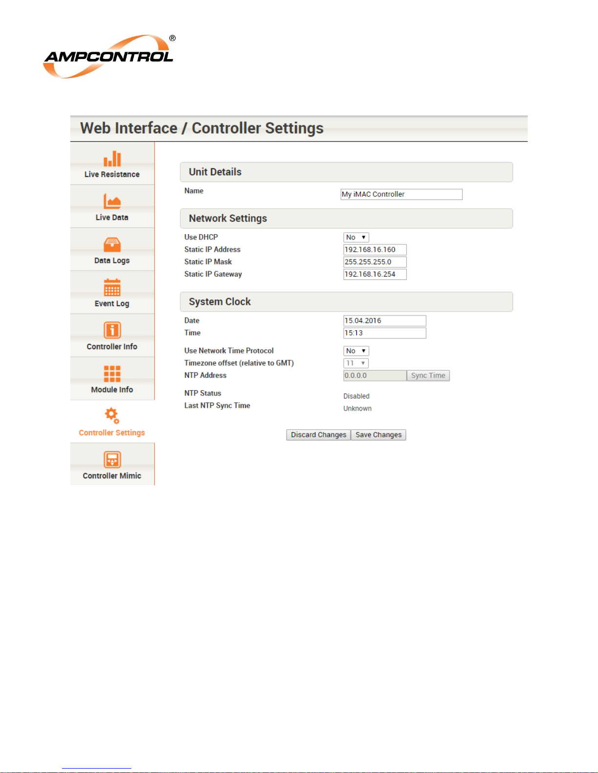
Navigate to the Ethernet Settings page to configure the IP settings for the iMAC2 Controller:
Figure 4: Updating the iMAC2 Controller Ethernet Port Settings
For information on this process, refer to the IMAC2B011 iMAC2 Controller Web Interface Manual.
IMAC2B015 V2 Uncontrolled Copy - Refer to Ampcontrol Website for Latest Version Page 9 of 41
Page 11

Ampcontrol Pty Ltd – ABN 28 000 915 542
iMAC2 Controller EtherNet/IP Communications Manual
IMAC2B015 V2 – 07/17
APPROVED FOR EXTERNAL DISTRIBUTION – PROPERTY OF AMPCONTROL PTY LTD – NOT TO BE REPRODUCED IN PART
iMAC Linespeed
EIP Packet Interval (max)
1000
100 ms
500
225 ms
300
400 ms
EtherNet/IP Protocol 2.3
The iMAC2 Controller uses industry standard EtherNet/IP protocol for exchanging data with compatible
Ethernet devices. The EtherNet/IP protocol is the adaptation of the Common Industrial Protocol to the
Ethernet platform. EtherNet/IP allows both implicit (synchronous) and Explicit (asynchronous) messaging,
with UDP port 2222 being used for implicit messages.
The iMAC2 data transfer is carried out via the following Assembly Instances:
Input Assembly Instance 100: defined by a block of 100 (16-bit) words.
Output Assembly Instance 150: defined by a block of 30 (16-bit) words. (Not currently used).
Config Assembly Instance 50: defined by a block of 0 bytes. (Not currently used).
The requested packet interval is configurable, and to guarantee all iMAC module data is sent to the PLC this
interval needs to be set to a rate faster than the iMAC controller is scanning its connected modules (referred
to as the iMAC Controller’s “linespeed”). The linespeed is set by the iMAC SLP code, and can be configured
in the range from 300 to 1000.
There are three commonly used linespeeds: 300, 500 and 1000. The following table specifies the maximum
EIP “packet interval time” that can be used for each of the commonly used linespeeds.
Table 3: Maximum EIP Packet Interval
The requested packet interval defaults to 225msec, with a maximum allowed being 400msec.
IMAC2B015 V2 Uncontrolled Copy - Refer to Ampcontrol Website for Latest Version Page 10 of 41
Page 12

Ampcontrol Pty Ltd – ABN 28 000 915 542
iMAC2 Controller EtherNet/IP Communications Manual
IMAC2B015 V2 – 07/17
APPROVED FOR EXTERNAL DISTRIBUTION – PROPERTY OF AMPCONTROL PTY LTD – NOT TO BE REPRODUCED IN PART
Word Offset
Description
0
Start Block Address
1
Module 1 Data
2
Module 1 Status
3
Module 1 Resistance
4
Module 1 ErrCnt
5
Module 2 Data
6
Module 2 Status
7
Module 2 Resistance
8
Module 2 ErrCnt
9
Module 3 Data
10
Module 3 Status
11
Module 3 Resistance
12
Module 3 ErrCnt
13
Module 4 Data
14
Module 4 Status
15
Module 4 Resistance
16
Module 4 ErrCnt
17
Unused
18
Unused
19
Unused
THE iMAC2 CONTROLLER’S DATA TRANSFER 3
The data transferred over EtherNet/IP is a progressive transfer of the iMAC2 data contained within the
iMAC2 Data Point Table. Each implicit message transfer updates the input assembly instance as follows:
Input Assembly Instance Layout 3.1
Table 4: iMAC2 Controller Input Assembly Instance Data Structure
IMAC2B015 V2 Uncontrolled Copy - Refer to Ampcontrol Website for Latest Version Page 11 of 41
Page 13

Ampcontrol Pty Ltd – ABN 28 000 915 542
iMAC2 Controller EtherNet/IP Communications Manual
IMAC2B015 V2 – 07/17
APPROVED FOR EXTERNAL DISTRIBUTION – PROPERTY OF AMPCONTROL PTY LTD – NOT TO BE REPRODUCED IN PART
20
System Status (Modbus 0x100)
21
System Control (Modbus 0x400)
22
System ID and Control (Modbus 0x401)
23
L1 Data Block Just Complete (Modbus 0x406)
24
Main Loop Timer Counter(SLP) (Modbus 0x408)
25
Module Rollcall Control (Modbus 0x409)
26
Rollcall Address (Modbus 0x40A)
27
Rollcall Serial Number (Modbus 0x40B)
28
Rollcall Type Register (Modbus 0x40C)
29
Rollcall Block Number (Modbus 0x40D)
30
Rollcall Parameter 1 (Modbus 0x40E)
31
Rollcall Parameter 2 (Modbus 0x40F)
32
Rollcall Parameter 3 (Modbus 0x410)
33
Rollcall Parameter 4 (Modbus 0x411)
34
Mimic Key Press (Modbus 0x60F)
35
SLP Fault Register (Modbus 0x50C)
36
SLP Fault Address (Modbus 0x50D)
37
Controller Hardware Flags (Modbus 0x600)
38
Controller Temperature (Modbus 0x601)
39
EOL Series Resistance (Modbus 0x200)
40
EOL Shunt Resistance (Modbus 0x300)
41
EOL Offline Count (Modbus 0x415)
42
EOL Clash Count (Modbus 0x416)
43
EOL Serial Number (Modbus 0x404)
44
MEOL Status (Modbus 0x0160)
IMAC2B015 V2 Uncontrolled Copy - Refer to Ampcontrol Website for Latest Version Page 12 of 41
Page 14

Ampcontrol Pty Ltd – ABN 28 000 915 542
iMAC2 Controller EtherNet/IP Communications Manual
IMAC2B015 V2 – 07/17
APPROVED FOR EXTERNAL DISTRIBUTION – PROPERTY OF AMPCONTROL PTY LTD – NOT TO BE REPRODUCED IN PART
45
MEOL Series Resistance (Modbus 0x260)
46
MEOL Offline / Clash Count (Modbus 0x360)
47
MEOL serial number (Modbus 0x060)
48
Unused
49
Unused
50 to 73
General Buffer Registers (24 of these) (Modbus 0x0480 to 0x0498)
74
Unused
75 to 98
Non Volatile Memory (24 registers) (Modbus 0x0520 to 0x0538)
99
Unused
Therefore, module data for four modules is sent from the iMAC2 at each packet time (offset 1 to 16), as well
as controller data (offset 20 to 37), EOL/MEOL module data (offset 38 to 47), General Buffer data (offset 50
to 73) and Non-Volatile Memory data (offset 75 to 98). The Start Block Address at offset 0 specifies the
node address of the first of four modules in each transfer. This Start Block Address is incremented by 4 for
each implicit message transfer. So that data for nodes 0, 1, 2 and 3 is updated at packet time t, then data for
nodes 4, 5, 6 and 7 is updated at packet time t+1, and so on until data for nodes 252, 253, 254 and 255 is
sent (at packet time t+63). Then the Start Block Address is reset to 0, and data for nodes 0, 1, 2 and 3 is
updated again.
Applications requiring iMAC2 data over EtherNet/IP need to take this progressive data update into account.
(This is taken care of in the RSLogix5000 Add-On Instruction described later).
Module Types 3.2
The table below provides the module types that are associated with the possible values of the “Rollcall
Type”. This is reproduced from the document “IMAC2B010 iMAC2 Controller Ethernet Communications
Manual”.
IMAC2B015 V2 Uncontrolled Copy - Refer to Ampcontrol Website for Latest Version Page 13 of 41
Page 15

Ampcontrol Pty Ltd – ABN 28 000 915 542
iMAC2 Controller EtherNet/IP Communications Manual
IMAC2B015 V2 – 07/17
APPROVED FOR EXTERNAL DISTRIBUTION – PROPERTY OF AMPCONTROL PTY LTD – NOT TO BE REPRODUCED IN PART
Module Type Table
Corresponding Values for Rollcall Type Register (Address 1036, 40Ch)
Value
Module Type
Value
Module Type
Decimal
Hexadecimal
Decimal
Hexadecimal
0
0000h
Reserved
32
0020h
LED4 Module
1
0001h
Controller
33
0021h
EMM Module
2
0002h
TCD2 DIPSwitch
34
0022h
Undefined #34
3
0003h
EOL Module
35
0023h
SIM-P Module
4
0004h
SQM Module
36
0024h
SIM-T Module
5
0005h
DI2/4 Module
37
0025h
SIM-G Module
6
0006h
Undefined #6
38
0026h
DI5 Module
7
0007h
Undefined #7
39
0027h
RO4 Module
8
0008h
TCD4 Long
40
0028h
TO4 Module
9
0009h
TCD4 Module
41
0029h
GCA Status
10
000Ah
RTD3 Status
42
002Ah
GCA 15Min Tally
11
000Bh
RTD3 Temp 1
43
002Bh
GCA 8Hr Tally
12
000Ch
RTD3 Temp 2
44
002Ch
GCA 24Hr Tally
13
000Dh
RTD3 Temp 3
45
002Dh
GCA Raw Count
14
000Eh
DI4L Module
46
002Eh
DI8 Module
15
000Fh
DI4 Module
47
002Fh
RIS Module
16
0010h
IIM Module
48
0030h
AIM Status
17
0011h
PGM-A Programr
49
0031h
AIM Analog
18
0012h
MEOL Module
50
0032h
AIM PwrSupply
19
0013h
TCD0 Module
51
0033h
CRM Module
20
0014h
SSW Status
52
0034h
ARM Module
21
0015h
SSW Control
53
0035h
GRM Module
22
0016h
SSW % Slip
54
0036h
RTD1 Status
23
0017h
SSW % Speed
55
0037h
RTD1 Temp
24
0018h
SSW Linr Speed
56
0038h
SIM-G2 Module
25
0019h
TCRD Input
57
0039h
FCP DigInputs
26
001Ah
TCRD Output
58
003Ah
FCP DigOutputs
27
001Bh
GAI3 Status
59
003Bh
FCP AnaInputs
28
001Ch
GAI3 Analogue #1
60
003Ch
FCP AnaOutputs
29
001Dh
GAI3 Analogue #2
61
003Dh
Undefined #61
30
001Eh
GAI3 Analogue #3
62
003Eh
Undefined #62
31
001Fh
RKM Keypad
63
003Fh
Undefined #63
Table 5: Module type designations.
IMAC2B015 V2 Uncontrolled Copy - Refer to Ampcontrol Website for Latest Version Page 14 of 41
Page 16

Ampcontrol Pty Ltd – ABN 28 000 915 542
iMAC2 Controller EtherNet/IP Communications Manual
IMAC2B015 V2 – 07/17
APPROVED FOR EXTERNAL DISTRIBUTION – PROPERTY OF AMPCONTROL PTY LTD – NOT TO BE REPRODUCED IN PART
Member
Name
Data
Type
Description
RefreshCycle
BOOL
Set by the controller at the end of every refresh cycle (refresh cycle = all 255
module addresses have been scanned). May be cleared by writing a 0 into this
bit using application (SLP) software.
L1ChksErr
BOOL
Set by the controller when a checksum error is detected on L1 fieldbus. May be
cleared by writing a 0 into this bit using application (SLP) software.
L1Ok
BOOL
Set by the controller when a L1 fieldbus scan completes with no errors detected.
May be cleared by writing a 0 into this bit using application (SLP) software.
L2ChksErr
BOOL
Set by the controller when a checksum error is detected on L2 fieldbus. May be
cleared by writing a 0 into this bit using application (SLP) software.
L2Active
BOOL
Set by controller when it detects an active fieldbus from another controller on its
L2 port. Often used to condition the operation of the L2 LED on the controller.
CtrlRelayState
BOOL
Status of the Control Relay. 1 = Energised. 0 = De-energised.
AuxRelayState
BOOL
Status of the Auxiliary Relay. 1 = Energised. 0 = De-energised.
EOL_OK
BOOL
Set by controller when EOL module is being detected on the L1 fieldbus with no
faults, clear otherwise.
EOL_SC
BOOL
Set by controller when the L1 fieldbus is short circuited (R<1000Ω), clear
otherwise
EOL_OC
BOOL
Set by controller when EOL module is not detected on the L1 fieldbus and the
fieldbus is not short circuited, clear otherwise.
EOL_CLASH
BOOL
Set by controller when two EOL modules are detected on the L1 fieldbus, clear
otherwise.
DATA HANDLING – RSLogix5000 APPLICATIONS 4
A set of RSLogix5000 user-defined data types (UDTs) and add-on instructions (AOIs) have been
constructed to retrieve iMAC2 data over the new EtherNet/IP connection, for connection to ControlLogix
PLCs. These components will be described here.
UDTs 4.1
There are module-specific UDTs, as well as generic UDTs used by the module-specific UDTs. These will all
be described in a logical order.
4.1.1 iMac_SystemStatus_DT
This UDT stores the iMAC2 Controller Runtime System Status bits. It is used by iMac_Ctrl_Runtime_DT. It
has the following members.
IMAC2B015 V2 Uncontrolled Copy - Refer to Ampcontrol Website for Latest Version Page 15 of 41
Page 17

Ampcontrol Pty Ltd – ABN 28 000 915 542
iMAC2 Controller EtherNet/IP Communications Manual
IMAC2B015 V2 – 07/17
APPROVED FOR EXTERNAL DISTRIBUTION – PROPERTY OF AMPCONTROL PTY LTD – NOT TO BE REPRODUCED IN PART
UART_Rx
BOOL
Set by controller when its serial port is receiving data
UART_Tx
BOOL
Set by controller when its serial port is transmitting data
EOL_SC
BOOL
Set by controller when the L1 fieldbus is short circuited (R<1000Ω), clear
otherwise
Member Name
Data
Type
Description
StartUp
BOOL
Set by controller on first SLP loop following power up
Always1
BOOL
This bit is always set to 1
SeqDownFromL2
BOOL
Sequence Down Bit from Upstream iMAC Controller
SeqUpFromL1
BOOL
Sequence Up Bit from Downstream iMAC Controller/SQM module
SwInput1
BOOL
iMAC Controller SW1 status: 1 = closed, 0 = open.
SwInput2
BOOL
iMAC Controller SW2 status: 1 = closed, 0 = open.
SwInput3
BOOL
iMAC Controller SW3 status: 1 = closed, 0 = open.
AsrtCtrlRelay
BOOL
Set by application (SLP) software to attempt to energise the CR relay. CR will
energise if and only if EOL Module comms is also healthy. Clear to deenergise CR relay.
AsrtAuxRelay
BOOL
Set by application (SLP) software to energise AR relay. Clear to de-energise
AR relay.
SeqUpOnL2
BOOL
Upstream sequence control bit
SeqDownOnL1
BOOL
Downstream sequence control bit
EnFlashWrite
BOOL
Enables data to be written to the iMAC Controller’s flash memory using
Modbus write commands
FullSysMenu
BOOL
The following menu functions are disabled when FullSysMenu = 0 & enabled
when FullSysMenu = 1 - System Menu ‘CLR DPT’ item, Maintenance page
F1 - Clear individual OnScan Bit
MinSysMenu
BOOL
The following menu functions are disabled when MinSysMenu = 0 & enabled
when MinSysMenu = 1 - System Menu (SHIFT+MENU), Debug Menu,
4.1.2 iMac_SystemControl_DT
This UDT stores the iMAC2 Controller Runtime System Control bits. It is used by iMac_Ctrl_Runtime_DT. It
has the following members.
IMAC2B015 V2 Uncontrolled Copy - Refer to Ampcontrol Website for Latest Version Page 16 of 41
Page 18

Ampcontrol Pty Ltd – ABN 28 000 915 542
iMAC2 Controller EtherNet/IP Communications Manual
IMAC2B015 V2 – 07/17
APPROVED FOR EXTERNAL DISTRIBUTION – PROPERTY OF AMPCONTROL PTY LTD – NOT TO BE REPRODUCED IN PART
Maintenance page F4 – Clear individual OFFLINE/CLASH COUNTERS
DisableWriteCmds
BOOL
Prevents Modbus Master devices writing to iMAC Controller Modbus
registers
Member Name
Data Type
Description
SystemStatus
iMac_SystemStatus_DT
System Status
SystemControl
iMac_SystemControl_DT
System Control
SysIdLeds
INT
System ID and LED control
L1BlockJustDone
INT
L1 Data Block Just Complete
LoopTimeSLP
INT
Main Loop Timer Counter (SLP)
RollcallControl
INT
Module Rollcall Control
RollcallAddress
INT
Rollcall Address
RollcallSerNum
INT
Rollcall Serial Number
RollcallModType
INT
Rollcall Type Register
RollcallBlckNum
INT
Rollcall Block Number
RollcallParam1
INT
Rollcall Parameter 1
RollcallParam2
INT
Rollcall Parameter 2
RollcallParam3
INT
Rollcall Parameter 3
RollcallParam4
INT
Rollcall Parameter 4
MimicKeyPress
INT
Mimic Key Press
SLPFaultRegister
INT
SLP Fault Register
SLPFaultAddress
INT
SLP Fault Address
HardwareFlags
INT
Controller Hardware Flags
ControllerTemp
INT
Controller Temperature
4.1.3 iMac_Ctrl_Runtime_DT
This UDT stores the iMAC2 Controller Runtime data. It is used by iMac_Controller_DT. It has the following
members.
IMAC2B015 V2 Uncontrolled Copy - Refer to Ampcontrol Website for Latest Version Page 17 of 41
Page 19

Ampcontrol Pty Ltd – ABN 28 000 915 542
iMAC2 Controller EtherNet/IP Communications Manual
IMAC2B015 V2 – 07/17
APPROVED FOR EXTERNAL DISTRIBUTION – PROPERTY OF AMPCONTROL PTY LTD – NOT TO BE REPRODUCED IN PART
Member Name
Data Type
Description
LCD_String_Data_Row1
INT[10]
LCD String Data Row 1
LCD_String_Data_Row2
INT[10]
LCD String Data Row 2
LCD_String_Data_Row3
INT[10]
LCD String Data Row 3
LCD_String_Data_Row4
INT[10]
LCD String Data Row 4
LCD_Cursor_Location
INT
LCD Cursor Location
EOL_Status
INT
EOL Status
EOL_Series_Resistance
INT
EOL Series Resistance
EOL_Shunt_Resistance
INT
EOL Shunt Resistance
EOLS_OC
INT
EOL Offline Count
EOLS_Clash
INT
EOL Clash Count
EOL_SerNum
INT
EOL Serial Number
MEOL_Status
INT
MEOL Status
MEOL_Series_Resistance
INT
MEOL Series Resistance
MEOLS_Offline_Clash_Count
INT
MEOL Offline + Clash Count
MEOL_SerNum
INT
MEOL Serial Number
Member Name
Data Type
Description
DATA
INT[256]
Controller Data.
STATUS
INT[256]
Controller Status.
4.1.4 iMac_Ctrl_LCD_DT
This UDT stores the iMAC2 Controller LCD data. It is included in the iMac_Controller_DT, but is not
currently used. It has the following members.
4.1.5 iMac_Controller_DT
This UDT stores the iMAC2 Controller data, including the data for all possible 256 modules in an iMAC
network. It is a stand-alone data type. It has the following members.
IMAC2B015 V2 Uncontrolled Copy - Refer to Ampcontrol Website for Latest Version Page 18 of 41
Page 20

Ampcontrol Pty Ltd – ABN 28 000 915 542
iMAC2 Controller EtherNet/IP Communications Manual
IMAC2B015 V2 – 07/17
APPROVED FOR EXTERNAL DISTRIBUTION – PROPERTY OF AMPCONTROL PTY LTD – NOT TO BE REPRODUCED IN PART
RESIST
INT[256]
Controller Resistance entries.
ERROR
INT[256]
Controller Errors.
Runtime
iMac_Ctrl_Runtime_DT
Run-time data.
LCD
iMac_Ctrl_LCD_DT
LCD-related data.
GENBUFF
INT[24]
General Buffer registers (area 480).
NVM
INT[24]
User NVM registers (area 520).
Member Name
Data
Type
Description
Module_Type
DINT
Network types are listed in the document 'IMAC2B010 iMAC2 Controller
Ethernet Communications Manual'
Module_Type_Data1
DINT
Type Data1 is: For SIM_G, SIM-G2, SIM-P and SIM-T modules: references
the SIM-G, SIM-G2, SIM-P and SIM-T unit;
for all other modules, this member is currently not used.
Module_Type_Data2
DINT
Type Data2 is: For SIM_G, SIM-G2, SIM-P and SIM-T modules: this
member references the register index; for all other modules, this member is
currently not used.
Note that the LCD data is not currently retrieved from the iMAC2 over EtherNet/IP, and so the LCD member
is empty.
4.1.6 iMac_Network_Config_Entry_DT
This UDT defines the iMAC2 network configuration Lookup table entry data. It is used by
iMac_Network_Config_DT. It has the following members.
Note that the Module_Type member has type numbers that follow the numbering defined in the iMAC2
system, and reproduced in Table 5: Module type designations.
IMAC2B015 V2 Uncontrolled Copy - Refer to Ampcontrol Website for Latest Version Page 19 of 41
Page 21

Ampcontrol Pty Ltd – ABN 28 000 915 542
iMAC2 Controller EtherNet/IP Communications Manual
IMAC2B015 V2 – 07/17
APPROVED FOR EXTERNAL DISTRIBUTION – PROPERTY OF AMPCONTROL PTY LTD – NOT TO BE REPRODUCED IN PART
Member
Name
Data Type
Description
Lookup_Table
iMac_Network_Config_Entry_DT[256]
The configuration of up to 256 iMAC modules in a
network attached to an iMAC controller; each
module is identified by the module type.
Member
Name
Data
Type
Description
OnScanBit
BOOL
Set by the controller when it first detects an input module address online on its L1
fieldbus. May be cleared by application (SLP) software. (POR=0)
L1ClashBit
BOOL
Set by the controller when two input modules transmit different data on the same
address, clear otherwise.
Global
BOOL
Must be intentionally set by application (SLP) software if the corresponding data
address needs to be published up the L2 fieldbus, thus making it a Global
Address.
L1OwnBit
BOOL
Set by the controller when it detects an input module address on its L1 fieldbus,
cleared if module not detected.
L2OwnBit
BOOL
Set by the controller when it detects the corresponding address on its L2 fieldbus.
The Global Select bit for this address must be set to allow the controller to “see”
up its L2 fieldbus. This should be done during the STARTUP segment of the
application (SLP) software.
SysOwnBit
BOOL
Must be intentionally set application (SLP) software when the corresponding data
register is to be owned by the system. Setting this bit forces the corresponding
data register to be an output. All addresses are assumed to be an input unless
this bit is set. If an input module is connected to a system owned address on L1, a
L1 clash error will occur.
L2ClashBit
BOOL
Set by the controller when it detects the address is Online on both its L1 and L2
ports if the address Global Select bit is set.
HighByteBit
BOOL
Must be intentionally set by application (SLP) software when the corresponding
data register is to be partially owned by the system. Low byte of data register
4.1.7 iMac_Network_Config_DT
This UDT stores the iMAC2 network configuration information (the lookup table). It has one member as
follows.
4.1.8 iMac_STATUS_DT
This UDT stores the iMAC Status Bit information. It is used by all module UDTs to be described hereafter. It
has the following members.
IMAC2B015 V2 Uncontrolled Copy - Refer to Ampcontrol Website for Latest Version Page 20 of 41
Page 22

Ampcontrol Pty Ltd – ABN 28 000 915 542
iMAC2 Controller EtherNet/IP Communications Manual
IMAC2B015 V2 – 07/17
APPROVED FOR EXTERNAL DISTRIBUTION – PROPERTY OF AMPCONTROL PTY LTD – NOT TO BE REPRODUCED IN PART
remains as input, but SLP can now write into high byte for output functions.
GenPurpose0
BOOL
General purpose use in application (SLP) software.
GenPurpose1
BOOL
General purpose use in application (SLP) software.
GenPurpose2
BOOL
General purpose use in application (SLP) software.
GenPurpose3
BOOL
General purpose use in application (SLP) software.
GenPurpose4
BOOL
General purpose use in application (SLP) software.
GenPurpose5
BOOL
General purpose use in application (SLP) software.
GenPurpose6
BOOL
General purpose use in application (SLP) software.
GenPurpose7
BOOL
General purpose use in application (SLP) software.
Member Name
Data
Type
Description
Module_Offline_Count
INT
This count is incremented every data scan that there is no owner of the
module address for which there was once an owner.
Module_Clash_Count
INT
This count is incremented every time that a data scan occurs when L1
Clash = 1 (ie increments each time an address is scanned for which there
are two modules with the same address that are transmitting different
input data).
Member Name
Data Type
Description
AIM_Analogue_Input
INT
Module Analogue Input
AIM_Analogue_Status
iMac_STATUS_DT
Module Status
AIM_Analogue_Resist
INT
Module Resistance Value
4.1.9 iMac_ERROR_DT
This UDT stores the iMAC module Error information. It is used by most of the module UDTs to be described
hereafter. It has the following members.
4.1.10 iMac_AIM_AI_ModDT
This UDT stores the iMAC AIM Analog Input Module Data Type information (Note – all UDTs for iMAC
modules have names ending with _ModDT, to distinguish them from other generic UDTs defined here). It
has the following members.
IMAC2B015 V2 Uncontrolled Copy - Refer to Ampcontrol Website for Latest Version Page 21 of 41
Page 23

Ampcontrol Pty Ltd – ABN 28 000 915 542
iMAC2 Controller EtherNet/IP Communications Manual
IMAC2B015 V2 – 07/17
APPROVED FOR EXTERNAL DISTRIBUTION – PROPERTY OF AMPCONTROL PTY LTD – NOT TO BE REPRODUCED IN PART
AIM_Analogue_Errors
iMac_ERROR_DT
Module Error Counters
Member Name
Data Type
Description
AIM_FLAGS_Bit0_AI_LT_SP3
BOOL
Module Flags - Analogue input < Set point 1
AIM_FLAGS_Bit1_AI_GE_SP2
BOOL
Module Flags - Analogue input >= Set point 2
AIM_FLAGS_Bit2_AI_GE_SP3
BOOL
Module Flags - Analogue input >= Set point 3
AIM_FLAGS_Bit3_AI_betw_1_2
BOOL
Module Flags - Set point 1 ≤ Analogue input < Set
point 2
AIM_FLAGS_Bit4_AI_betw_2_3
BOOL
Module Flags - Set point 2 ≤ Analogue input < Set
point 3
AIM_FLAGS_Bit5_PS_LT_SPA
BOOL
Module Flags - Power Supply < SP A (warn)
AIM_FLAGS_Bit6_PS_LT_SPB
BOOL
Module Flags - Power Supply < SP B (trip)
AIM_FLAGS_Status
iMac_STATUS_DT
Module Status
AIM_FLAGS_Resist
INT
Module Resistance Value
AIM_FLAGS_Errors
iMac_ERROR_DT
Module Error Counters
Member Name
Data Type
Description
AIM_Power_Supply
INT
Module Power Supply Data
AIM_Power_Supply_Status
iMac_STATUS_DT
Module Status
AIM_Power_Supply_Resist
INT
Module Resistance Value
Note that all module-related UDTs have the specific Data members, plus status bits, resistance value and
error counts (although the LED4 and RO4 modules don’t have resistance or error members, and the IIM
Module has an extra IIM_LEDs member).
4.1.11 iMac_AIM_FLAGS_ModDT
This UDT stores the iMAC AIM Analog Flags Module Data Type information. It has the following members.
4.1.12 iMac_AIM_Power_ModDT
This UDT stores the iMAC AIM Power Supply Module data. It has the following members.
IMAC2B015 V2 Uncontrolled Copy - Refer to Ampcontrol Website for Latest Version Page 22 of 41
Page 24

Ampcontrol Pty Ltd – ABN 28 000 915 542
iMAC2 Controller EtherNet/IP Communications Manual
IMAC2B015 V2 – 07/17
APPROVED FOR EXTERNAL DISTRIBUTION – PROPERTY OF AMPCONTROL PTY LTD – NOT TO BE REPRODUCED IN PART
AIM_Power_Supply_Errors
iMac_ERROR_DT
Module Error Counters
Member Name
Data Type
Description
DI4_Inputs_IP1
BOOL
Module Input IP1
DI4_Inputs_IP2
BOOL
Module Input IP2
DI4_Inputs_IP3
BOOL
Module Input IP3
DI4_Inputs_IP4
BOOL
Module Input IP4
DI4_Inputs_Applic_Dept
SINT
Module Input Data High Byte - Application Dependent
DI4_Status
iMac_STATUS_DT
Module Status
DI4_Resist
INT
Module Resistance Value
DI4_Errors
iMac_ERROR_DT
Module Error Counters
Member Name
Data Type
Description
DI8_Inputs_IP1
BOOL
Module Input IP1
DI8_Inputs_IP2
BOOL
Module Input IP2
DI8_Inputs_IP3
BOOL
Module Input IP3
DI8_Inputs_IP4
BOOL
Module Input IP4
DI8_Inputs_IP5
BOOL
Module Input IP5
DI8_Inputs_IP6
BOOL
Module Input IP6
DI8_Inputs_IP7
BOOL
Module Input IP7
DI8_Inputs_IP8
BOOL
Module Input IP8
4.1.13 iMac_DI4_ModDT
This UDT stores the iMAC DI4 Module data. It has the following members.
4.1.14 iMac_DI8_ModDT
This UDT stores the iMAC DI8 Module data. It has the following members.
IMAC2B015 V2 Uncontrolled Copy - Refer to Ampcontrol Website for Latest Version Page 23 of 41
Page 25

Ampcontrol Pty Ltd – ABN 28 000 915 542
iMAC2 Controller EtherNet/IP Communications Manual
IMAC2B015 V2 – 07/17
APPROVED FOR EXTERNAL DISTRIBUTION – PROPERTY OF AMPCONTROL PTY LTD – NOT TO BE REPRODUCED IN PART
DI8_Inputs_Applic_Dept
SINT
Module Input Data High Byte - Application Dependent
DI8_Status
iMac_STATUS_DT
Module Status
DI8_Resist
INT
Module Resistance Value
DI8_Errors
iMac_ERROR_DT
Module Error Counters
Member Name
Data Type
Description
GAI3_FLAGS_Bit0_AI1_ALM
BOOL
Module Flags - Analogue input 1 Alarm Bit
(1=Alarm; 0=No Alarm).
GAI3_FLAGS_Bit1_AI2_ALM
BOOL
Module Flags - Analogue input 2 Alarm Bit
(1=Alarm; 0=No Alarm).
GAI3_FLAGS_Bit2_AI3_ALM
BOOL
Module Flags - Analogue input 3 Alarm Bit
(1=Alarm; 0=No Alarm).
GAI3_FLAGS_Bit3_ADC_Fail
BOOL
Module Flags - GAI3 Internal Fault (ADC Fail)
(1=Fault; 0=No Fault).
GAI3_FLAGS_Bit8_AI1_OL_Status
BOOL
Module Flags - AI Module 1 Online Status
(1=Online; 0=Offline).
GAI3_FLAGS_Bit9_AI2_OL_Status
BOOL
Module Flags - AI Module 2 Online Status
(1=Online; 0=Offline).
GAI3_FLAGS_Bit10_AI3_OL_Status
BOOL
Module Flags - AI Module 3 Online Status
(1=Online; 0=Offline).
GAI3_FLAGS_Status
iMac_STATUS_DT
Module Status
GAI3_FLAGS_Resist
INT
Module Resistance Value
GAI3_FLAGS_Errors
iMac_ERROR_DT
Module Error Counters
4.1.15 iMac_GAI3_FLAGS_ModDT
This UDT stores the iMAC GAI3 Module Status data. It has the following members.
IMAC2B015 V2 Uncontrolled Copy - Refer to Ampcontrol Website for Latest Version Page 24 of 41
Page 26

Ampcontrol Pty Ltd – ABN 28 000 915 542
iMAC2 Controller EtherNet/IP Communications Manual
IMAC2B015 V2 – 07/17
APPROVED FOR EXTERNAL DISTRIBUTION – PROPERTY OF AMPCONTROL PTY LTD – NOT TO BE REPRODUCED IN PART
Member Name
Data Type
Description
GAI3_Analogue_Input
INT
Module Analogue Input
GAI3_Analogue_Status
iMac_STATUS_DT
Module Status
GAI3_Analogue_Resist
INT
Module Resistance Value
GAI3_Analogue_Errors
iMac_ERROR_DT
Module Error Counters
Member Name
Data Type
Description
IIM_Inputs_IP1
BOOL
Module Input IP1
IIM_Inputs_IP2
BOOL
Module Input IP2
IIM_Inputs_IP3
BOOL
Module Input IP3
IIM_Inputs_IP4
BOOL
Module Input IP4
IIM_Inputs_IP5
BOOL
Module Input IP5
IIM_Inputs_Bit5_ALine_Monitor_IP
BOOL
Module Input Data - A-line Monitor IP
IIM_Inputs_Bit7_RandomBit
BOOL
Module Input Data - Random Bit
IIM_Inputs_Applic_Dept
SINT
Module Input Data High Byte - Application
Dependent
IIM_Status
iMac_STATUS_DT
Module Status
IIM_Resist
INT
Module Resistance Value
IIM_Errors
iMac_ERROR_DT
Module Error Counters
IIM_LEDs
INT
LED Output Data
4.1.16 iMac_GAI3_AI_ModDT
This UDT stores the iMAC GAI3 Module Analogue data. It is used for the three analogue values associated
with the GAI3 module. It has the following members.
4.1.17 iMac_IIM_ModDT
This UDT stores the iMAC IIM Module data. It has the following members.
IMAC2B015 V2 Uncontrolled Copy - Refer to Ampcontrol Website for Latest Version Page 25 of 41
Page 27

Ampcontrol Pty Ltd – ABN 28 000 915 542
iMAC2 Controller EtherNet/IP Communications Manual
IMAC2B015 V2 – 07/17
APPROVED FOR EXTERNAL DISTRIBUTION – PROPERTY OF AMPCONTROL PTY LTD – NOT TO BE REPRODUCED IN PART
Member Name
Data Type
Description
LED4_Outputs_LED1
BOOL
Module Output LEDs - LED1
LED4_Outputs_LED2
BOOL
Module Output LEDs - LED2
LED4_Outputs_LED3
BOOL
Module Output LEDs - LED3
LED4_Outputs_LED4
BOOL
Module Output LEDs - LED4
LED4_Status
iMac_STATUS_DT
Module Status
Member Name
Data Type
Description
RIS_Inputs_IP1
BOOL
Module Input IP1
RIS_Inputs_IP2
BOOL
Module Input IP2
RIS_Inputs_IP3
BOOL
Module Input IP3
RIS_Inputs_IP4
BOOL
Module Input IP4
RIS_Inputs_IP5
BOOL
Module Input IP5
RIS_Inputs_Bit5_ALine_Monitor_IP
BOOL
Module Input Data - A-line Monitor IP
RIS_Inputs_Bit7_RandomBit
BOOL
Module Input Data - Random Bit
RIS_Inputs_Applic_Dept
SINT
Module Input Data High Byte - Application
Dependent
RIS_Status
iMac_STATUS_DT
Module Status
RIS_Resist
INT
Module Resistance Value
RIS_Errors
iMac_ERROR_DT
Module Error Counters
RIS_LEDs
INT
LED Output Data
4.1.18 iMac_LED4_ModDT
This UDT stores the iMAC LED4 Module data. It has the following members.
4.1.19 iMac_RIS_ModDT
This UDT stores the iMAC RIS Module data. It has the following members.
IMAC2B015 V2 Uncontrolled Copy - Refer to Ampcontrol Website for Latest Version Page 26 of 41
Page 28

Ampcontrol Pty Ltd – ABN 28 000 915 542
iMAC2 Controller EtherNet/IP Communications Manual
IMAC2B015 V2 – 07/17
APPROVED FOR EXTERNAL DISTRIBUTION – PROPERTY OF AMPCONTROL PTY LTD – NOT TO BE REPRODUCED IN PART
Member Name
Data Type
Description
RO4_Outputs_Relay1
BOOL
Module Output Relays - Relay 1
RO4_Outputs_Relay2
BOOL
Module Output Relays - Relay 2
RO4_Outputs_Relay3
BOOL
Module Output Relays - Relay 3
RO4_Outputs_Relay4
BOOL
Module Output Relays - Relay 4
RO4_Status
iMac_STATUS_DT
Module Status
Member Name
Data Type
Description
RTD1_FLAGS_Bit0_RTD_SC
BOOL
Module Flags - RTD Short Circuit
RTD1_FLAGS_Bit1_RTD_OC
BOOL
Module Flags - RTD Open Circuit
RTD1_FLAGS_Bit2_RTD_Wire_FLT
BOOL
Module Flags - RTD Sense Wire Fault
RTD1_FLAGS_Bit3_Temp_OOR
BOOL
Module Flags - RTD Temperature Out of
Range
RTD1_FLAGS_Bit4_Low_Temp
BOOL
Module Flags - RTD Low Temperature Alarm
RTD1_FLAGS_Bit5_High_Temp
BOOL
Module Flags - RTD High Temperature Alarm
RTD1_FLAGS_Status
iMac_STATUS_DT
Module Status
RTD1_FLAGS_Resist
INT
Module Resistance Value
RTD1_FLAGS_Errors
iMac_ERROR_DT
Module Error Counters
4.1.20 iMac_RO4_ModDT
This UDT stores the iMAC RO4 Isolation Output Module data. It has the following members.
4.1.21 iMac_RTD1_FLAGS_ModDT
This UDT stores the iMAC RTD1 Flags Module data. It has the following members.
IMAC2B015 V2 Uncontrolled Copy - Refer to Ampcontrol Website for Latest Version Page 27 of 41
Page 29

Ampcontrol Pty Ltd – ABN 28 000 915 542
iMAC2 Controller EtherNet/IP Communications Manual
IMAC2B015 V2 – 07/17
APPROVED FOR EXTERNAL DISTRIBUTION – PROPERTY OF AMPCONTROL PTY LTD – NOT TO BE REPRODUCED IN PART
Member Name
Data Type
Description
RTD_Temp_Input
INT
Module Temperature Input
RTD_Temp_Status
iMac_STATUS_DT
Module Status
RTD_Temp_Resist
INT
Module Resistance Value
RTD_Temp_Errors
iMac_ERROR_DT
Module Error Counters
Member Name
Data Type
Description
RTD3_FLAGS_Bit0_T1_ALM
BOOL
Module Flags - RTD3 Temp1 Alarm Setpoint
RTD3_FLAGS_Bit1_T2_ALM
BOOL
Module Flags - RTD3 Temp2 Alarm Setpoint
RTD3_FLAGS_Bit2_T3_ALM
BOOL
Module Flags - RTD3 Temp3 Alarm Setpoint
RTD3_FLAGS_Bit3_ADC_Fail
BOOL
Module Flags - RTD3 Internal Fault (ADC Fail)
RTD3_FLAGS_Bit4_T1_Temp_OOR
BOOL
Module Flags - RTD3 Temp1 Temperature Out
of Range
RTD3_FLAGS_Bit5_T2_Temp_OOR
BOOL
Module Flags - RTD3 Temp2 Temperature Out
of Range
RTD3_FLAGS_Bit6_T3_Temp_OOR
BOOL
Module Flags - RTD3 Temp3 Temperature Out
of Range
RTD3_FLAGS_Bit7_Calib_Error
BOOL
Module Flags - RTD3 Calibration Error
RTD3_FLAGS_Bit8_T1_OL_Status
BOOL
Module Flags - RTD3 Temp1 Online Status
RTD3_FLAGS_Bit9_T2_OL_Status
BOOL
Module Flags - RTD3 Temp2 Online Status
RTD3_FLAGS_Bit10_T3_OL_Status
BOOL
Module Flags - RTD3 Temp3 Online Status
RTD3_FLAGS_Bit12_T1_Wire_FLT
BOOL
Module Flags - RTD3 Temp1 Sense Wire Fault
RTD3_FLAGS_Bit13_T2_Wire_FLT
BOOL
Module Flags - RTD3 Temp3 Sense Wire Fault
4.1.22 iMac_RTD_Temp_ModDT
This UDT stores the iMAC RTD Temperature Input Module data. It can be used for RTD1 and RTD3
modules. It has the following members.
4.1.23 iMac_RTD3_FLAGS_ModDT
This UDT stores the iMAC RTD3 Flags Module data. It has the following members.
IMAC2B015 V2 Uncontrolled Copy - Refer to Ampcontrol Website for Latest Version Page 28 of 41
Page 30

Ampcontrol Pty Ltd – ABN 28 000 915 542
iMAC2 Controller EtherNet/IP Communications Manual
IMAC2B015 V2 – 07/17
APPROVED FOR EXTERNAL DISTRIBUTION – PROPERTY OF AMPCONTROL PTY LTD – NOT TO BE REPRODUCED IN PART
RTD3_FLAGS_Bit14_T3_Wire_FLT
BOOL
Module Flags - RTD3 Temp2 Sense Wire Fault
RTD1_FLAGS_Status
iMac_STATUS_DT
Module Status
RTD1_FLAGS_Resist
INT
Module Resistance Value
RTD1_FLAGS_Errors
iMac_ERROR_DT
Module Error Counters
Member Name
Data Type
Description
SIM_G_ALARMS_CH1_2
INT
Alarm Flags Channels 1 & 2
SIM_G_ALARMS_CH3_4
INT
Alarm Flags Channels 3 & 4
SIM_G_FLAGS
INT
Gasguard Flags
SIM_G_ANALOG_CH
INT[4]
Analogue Input Channels 1 to 4
SIM_G_DISPLAY_CH
INT[4]
Display Format Value Channels 1 to 4
SIM_G_RS485_ERRORS
INT
Error Count for RS 485 Communication
SIM_G_SERIAL_NUM
INT
SIM-G Serial Number
SIM_G_Status
iMac_STATUS_DT[16]
Module Status A0 to A15
SIM_G_Resist
INT[16]
Module Resistance Value A0 to A15
SIM_G_Error
iMac_ERROR_DT[16]
Module Error Counters A0 to A15
Member Name
Data Type
Description
SIM_G2_ALARMS_CH1_2_CTRL1
INT
Alarm Flags Channels 1 & 2, Controller 1
SIM_G2_ALARMS_CH3_4_CTRL1
INT
Alarm Flags Channels 3 & 4, Controller 1
SIM_G2_ALARMS_CH1_2_CTRL2
INT
Alarm Flags Channels 1 & 2, Controller 2
SIM_G2_ALARMS_CH3_4_CTRL2
INT
Alarm Flags Channels 3 & 4, Controller 2
4.1.24 iMac_SIM_G_ModDT
This UDT stores the iMAC SIM-G Module data. It has the following members.
4.1.25 iMac_SIM_G2_ModDT
This UDT stores the iMAC SIM-G2 Module data. It has the following members.
IMAC2B015 V2 Uncontrolled Copy - Refer to Ampcontrol Website for Latest Version Page 29 of 41
Page 31

Ampcontrol Pty Ltd – ABN 28 000 915 542
iMAC2 Controller EtherNet/IP Communications Manual
IMAC2B015 V2 – 07/17
APPROVED FOR EXTERNAL DISTRIBUTION – PROPERTY OF AMPCONTROL PTY LTD – NOT TO BE REPRODUCED IN PART
SIM_G2_ANALOG_CH_CTRL1
INT[4]
Analogue Input Channels 1 to 4, Controller 1
SIM_G2_DISPLAY_FORMATS
INT
Channel Display Format Values - Controllers
1 (low byte) and 2 (high byte).
SIM_G2_ANALOG_CH_CTRL2
INT[4]
Analogue Input Channels 1 to 4, Controller 2
SIM_G2_RS485_ERRORS_CTRL1
INT
Error Count for RS 485 Communication,
Controller 1
SIM_G2_RS485_ERRORS_CTRL2
INT
Error Count for RS 485 Communication,
Controller 2
SIM_G2_SERIAL_NUM
INT
SIM-G2 Serial Number
SIM_G2_Status
iMac_STATUS_DT[16]
Module Status A0 to A15
SIM_G2_Resist
INT[16]
Module Resistance Value A0 to A15
SIM_G2_Error
iMac_ERROR_DT[16]
Module Error Counters A0 to A15
Member Name
Data Type
Description
SIM_P_RS485_ERRORS
INT
Error Count for RS485 Communication
SIM_P_DATA_REGS
INT[16]
Data Registers 1 to 16
SIM_P_Status
iMac_STATUS_DT[17]
Module Status A0 to A16
SIM_P_Resist
INT[17]
Module Resistance Value A0 to A16
SIM_P_Error
iMac_ERROR_DT[17]
Module Error Counters A0 to A16
Member Name
Data Type
Description
SIM_T_ALARMS_CH1_4
INT
Alarm Flags Channels 1 to 4
SIM_T_ALARMS_CH5_8
INT
Alarm Flags Channels 5 to 8
4.1.26 iMac_SIM_P_ModDT
This UDT stores the iMAC SIM-P Module data. It has the following members.
4.1.27 iMac_SIM_T_ModDT
This UDT stores the iMAC SIM-T Module data. It has the following members.
IMAC2B015 V2 Uncontrolled Copy - Refer to Ampcontrol Website for Latest Version Page 30 of 41
Page 32

Ampcontrol Pty Ltd – ABN 28 000 915 542
iMAC2 Controller EtherNet/IP Communications Manual
IMAC2B015 V2 – 07/17
APPROVED FOR EXTERNAL DISTRIBUTION – PROPERTY OF AMPCONTROL PTY LTD – NOT TO BE REPRODUCED IN PART
SIM_T_INPUT_STATUS
INT
Trolex Input Status 1 to 8
SIM_T_RELAY_STATUS
INT
Trolex Relay Status 1 to 8
SIM_T_ANALOG_CH
INT[8]
Analogue Input Channels 1 to 8
SIM_T_SOFTWARE_VERSION
INT
Software Version *10 (Value divided by 10 ie 27
= version 2.7)
SIM_T_RS485_ERRORS
INT
Error Count for RS485 Communication
SIM_T_SERIAL_NUM
INT
SIM-T Serial Number
SIM_T_Status
iMac_STATUS_DT[16]
Module Status A0 to A15
SIM_T_Resist
INT[16]
Module Resistance Value A0 to A15
SIM_T_Error
iMac_ERROR_DT[16]
Module Error Counters A0 to A15
Member Name
Data Type
Description
SSW_Control_Bit0_Setup_Mode
BOOL
Module Flags - Setup mode (1=Busy); The
setup process is busy.
SSW_Control_Bit1_Setup_Success
BOOL
Module Flags - Setup successful (1=Success);
No failures occurred during the setup process.
SSW_Control_Bit2_Setup_Failed
BOOL
Module Flags - Setup failed (1=Failed); The
setup process failed due to a timeout or pulse
rate failure.
SSW_Control_Bit3_S1_Pulse_Slow
BOOL
Module Flags - Sensor 1 pulse rate too slow
(1=Failed); Rate < 50ppm.
SSW_Control_Bit4_S1_Pulse_Fast
BOOL
Module Flags - Sensor 1 pulse rate too fast
(1=Failed); Rate > 5000ppm.
SSW_Control_Bit5_S2_Pulse_Slow
BOOL
Module Flags - Sensor 2 pulse rate too slow
(1=Failed); Rate < 50ppm.
SSW_Control_Bit6_S2_Pulse_Fast
BOOL
Module Flags - Sensor 2 pulse rate too fast
(1=Failed); Rate > 5000ppm.
SSW_Control_Bit7_Setup_Timeout
BOOL
Module Flags - Setup timeout (1=Timeout);
Setup failed to complete within 4 minutes.
4.1.28 iMac_SSW_Control_ModDT
This UDT stores the iMAC SSW Module Control data. It has the following members.
IMAC2B015 V2 Uncontrolled Copy - Refer to Ampcontrol Website for Latest Version Page 31 of 41
Page 33

Ampcontrol Pty Ltd – ABN 28 000 915 542
iMAC2 Controller EtherNet/IP Communications Manual
IMAC2B015 V2 – 07/17
APPROVED FOR EXTERNAL DISTRIBUTION – PROPERTY OF AMPCONTROL PTY LTD – NOT TO BE REPRODUCED IN PART
SSW_Control_Bit8_MC_Belt_State
BOOL
Module Flags - MC (belt run state) (1=Running);
Usage: Indicate belt run condition.
SSW_Control_Bit9_Slip_Trip_Test
BOOL
Module Flags - Slip trip Test (1=Simulate trip);
Usage: Test trip mechanism.
SSW_Control_Bit10_Reset_Trips
BOOL
Module Flags - Reset latched trips (1=Reset);
Usage: Clear any latched trip flags;
Requirements: No persistent trips present.
SSW_Control_Bit11_Setup_Enable
BOOL
Module Flags - Setup enable (1=Enable);
Usage: Start the normalisation sequence;
Requirements: Belt stopped, trips cleared.
SSW_Control_Status
iMac_STATUS_DT
Module Status
SSW_Control_Resist
INT
Module Resistance Value
SSW_Control_Errors
iMac_ERROR_DT
Module Error Counters
Member Name
Data Type
Description
SSW_FLAGS_Bit0_Trip_Summary
BOOL
Module Flags - Trip summary (1=Trips exist);
An OR function of all 'Tripped' flags
SSW_FLAGS_Bit1_Brake_Relay
BOOL
Module Flags - Brake relay (1=Release); %
speed > Brake release set point
SSW_FLAGS_Bit2_Seq_Relay
BOOL
Module Flags - Sequence relay (1=Energized);
% Speed > Sequence relay activation set point
SSW_FLAGS_Bit3_CV_Stopped
BOOL
Module Flags - Conveyor stopped (1=Stopped);
No pulses on either sensor, for a period of 20x
slowest sensor pulse rate
SSW_FLAGS_Bit4_S1_Pulses_FLT
BOOL
Module Flags - Sensor 1 pulses fault
(1=Tripped); Inhibit timers expired, and drive
pulse rate = 0
SSW_FLAGS_Bit5_S2_Pulses_FLT
BOOL
Module Flags - Sensor 2 pulses fault
(1=Tripped); Inhibit timers expired, and drive
pulse rate = 0
SSW_FLAGS_Bit6_S1_Conn_FLT
BOOL
Module Flags - Sensor 1 connection fault
4.1.29 iMac_SSW_FLAGS_ModDT
This UDT stores the iMAC SSW Module Status data. It has the following members.
IMAC2B015 V2 Uncontrolled Copy - Refer to Ampcontrol Website for Latest Version Page 32 of 41
Page 34

Ampcontrol Pty Ltd – ABN 28 000 915 542
iMAC2 Controller EtherNet/IP Communications Manual
IMAC2B015 V2 – 07/17
APPROVED FOR EXTERNAL DISTRIBUTION – PROPERTY OF AMPCONTROL PTY LTD – NOT TO BE REPRODUCED IN PART
(1=Tripped); Drive Sensor is open/short circuit
SSW_FLAGS_Bit7_S2_Conn_FLT
BOOL
Module Flags - Sensor 2 connection fault
(1=Tripped); Idler Sensor is open/short circuit
SSW_FLAGS_Bit8_Slip_Trip
BOOL
Module Flags - Slip trip (1=Tripped); The
difference between belt and drive speed > slip
trip margin setting.
SSW_FLAGS_Bit9_UO_Speed_Err
BOOL
Module Flags - Idle roller Under/Over speed
(1=Tripped); Belt speed is outside the
under/over speed margin setting.
SSW_FLAGS_Bit10_Internal_Error
BOOL
Module Flags - SSW internal error (1=Tripped);
EEPROM Error (checked at node power-up)
SSW_FLAGS_Bit13_Slip_Inh_TMR
BOOL
Module Flags - Slip trip inhibit timer (1=Active);
Reload and timer start on MC 0 -> 1
SSW_FLAGS_Bit14_UO_Inh_TMR
BOOL
Module Flags - Under/Over trip inhibit timer
(1=Active); Reload and timer start on MC 0 -> 1
SSW_FLAGS_Bit15_Sensor_Num
BOOL
Module Flags - Number of sensors; 0=1 sensor
(Only an idler sensor exists.); 1=2 sensors
(There is both a drive and an idler sensor).
SSW_FLAGS_Status
iMac_STATUS_DT
Module Status
SSW_FLAGS_Resist
INT
Module Resistance Value
SSW_FLAGS_Errors
iMac_ERROR_DT
Module Error Counters
Member Name
Data Type
Description
SSW_Value
INT
Module Register Value
SSW_Value_Status
iMac_STATUS_DT
Module Status
SSW_Value_Resist
INT
Module Resistance Value
SSW_Value_Errors
iMac_ERROR_DT
Module Error Counters
4.1.30 iMac_SSW_Value_ModDT
This UDT stores the iMAC SSW Module % Slip, % Speed or Linear Speed value data. It has the following
members.
IMAC2B015 V2 Uncontrolled Copy - Refer to Ampcontrol Website for Latest Version Page 33 of 41
Page 35

Ampcontrol Pty Ltd – ABN 28 000 915 542
iMAC2 Controller EtherNet/IP Communications Manual
IMAC2B015 V2 – 07/17
APPROVED FOR EXTERNAL DISTRIBUTION – PROPERTY OF AMPCONTROL PTY LTD – NOT TO BE REPRODUCED IN PART
Member Name
Data Type
Description
AIM_FLAGS_Modules
iMac_AIM_FLAGS_ModDT[256]
Storage for data from up to 256 of these
modules in a network.
AIM_AI_Modules
iMac_AIM_AI_ModDT[256]
Storage for data from up to 256 of these
modules in a network.
AIM_Power_Modules
iMac_AIM_Power_ModDT[256]
Storage for data from up to 256 of these
modules in a network.
DI4_Modules
iMac_DI4_ModDT[256]
Storage for data from up to 256 of these
modules in a network.
DI8_Modules
iMac_DI8_ModDT[256]
Storage for data from up to 256 of these
modules in a network.
GAI3_FLAGS_Modules
iMac_GAI3_FLAGS_ModDT[256]
Storage for data from up to 256 of these
modules in a network.
GAI3_Analog1_Modules
iMac_GAI3_AI_ModDT[256]
Storage for data from up to 256 of these
modules in a network.
GAI3_Analog2_Modules
iMac_GAI3_AI_ModDT[256]
Storage for data from up to 256 of these
modules in a network.
GAI3_Analog3_Modules
iMac_GAI3_AI_ModDT[256]
Storage for data from up to 256 of these
modules in a network.
IIM_Modules
iMac_IIM_ModDT[256]
Storage for data from up to 256 of these
modules in a network.
LED4_Modules
iMac_LED4_ModDT[256]
Storage for data from up to 256 of these
modules in a network.
RIS_Modules
iMac_RIS_ModDT[256]
Storage for data from up to 256 of these
modules in a network.
RO4_Modules
iMac_RO4_ModDT[256]
Storage for data from up to 256 of these
modules in a network.
RTD1_FLAGS_Modules
iMac_RTD1_FLAGS_ModDT[256]
Storage for data from up to 256 of these
modules in a network.
RTD1_Temp_Modules
iMac_RTD_Temp_ModDT[256]
Storage for data from up to 256 of these
modules in a network.
4.1.31 iMac_Modules_DT
This UDT stores iMAC Module data for all possible types of modules in a network of 256 modules. It has the
following members.
IMAC2B015 V2 Uncontrolled Copy - Refer to Ampcontrol Website for Latest Version Page 34 of 41
Page 36

Ampcontrol Pty Ltd – ABN 28 000 915 542
iMAC2 Controller EtherNet/IP Communications Manual
IMAC2B015 V2 – 07/17
APPROVED FOR EXTERNAL DISTRIBUTION – PROPERTY OF AMPCONTROL PTY LTD – NOT TO BE REPRODUCED IN PART
RTD3_FLAGS_Modules
iMac_RTD3_FLAGS_ModDT[256]
Storage for data from up to 256 of these
modules in a network.
RTD3_Temp1_Modules
iMac_RTD_Temp_ModDT[256]
Storage for data from up to 256 of these
modules in a network.
RTD3_Temp2_Modules
iMac_RTD_Temp_ModDT[256]
Storage for data from up to 256 of these
modules in a network.
RTD3_Temp3_Modules
iMac_RTD_Temp_ModDT[256]
Storage for data from up to 256 of these
modules in a network.
SIM_G_Modules
iMac_SIM_G_ModDT[16]
Storage for data from up to 16 of these
modules in a network.
SIM_G2_Modules
iMac_SIM_G2_ModDT[16]
Storage for data from up to 16 of these
modules in a network.
SIM_P_Modules
iMac_SIM_P_ModDT[128]
Storage for data from up to 128 of these
modules in a network.
SIM_T_Modules
iMac_SIM_T_ModDT[16]
Storage for data from up to 16 of these
modules in a network.
SSW_FLAGS_Modules
iMac_SSW_FLAGS_ModDT[256]
Storage for data from up to 256 of these
modules in a network.
SSW_Control_Modules
iMac_SSW_Control_ModDT[256]
Storage for data from up to 256 of these
modules in a network.
SSW_PC_Slip_Modules
iMac_SSW_Value_ModDT[256]
Storage for data from up to 256 of these
modules in a network.
SSW_PC_Speed_Modules
iMac_SSW_Value_ModDT[256]
Storage for data from up to 256 of these
modules in a network.
SSW_Linr_Speed_Modules
iMac_SSW_Value_ModDT[256]
Storage for data from up to 256 of these
modules in a network.
IMAC2B015 V2 Uncontrolled Copy - Refer to Ampcontrol Website for Latest Version Page 35 of 41
Page 37

Ampcontrol Pty Ltd – ABN 28 000 915 542
iMAC2 Controller EtherNet/IP Communications Manual
IMAC2B015 V2 – 07/17
APPROVED FOR EXTERNAL DISTRIBUTION – PROPERTY OF AMPCONTROL PTY LTD – NOT TO BE REPRODUCED IN PART
Name
Usage
Data Type
Description
InputAssembly
InOut
INT[100]
Input assembly data from Ethernet
iMac_Network_Config
InOut
iMac_Network_Config_DT
iMAC network configuration lookup table.
iMac_Controller
InOut
iMac_Controller_DT
iMAC Controller UDT
iMac_Modules
InOut
iMac_Modules_DT
All bug data.
Name
Usage
Data Type
Description
iMac_Controller
InOut
iMac_Controller_DT
iMAC Controller UDT
iMac_Modules
InOut
iMac_Modules_DT
All bug data.
AOIs 4.2
This subsection will describe four RSLogix5000 add-on instructions that have been written for retrieving the
EtherNet/IP data from the iMAC2. Instruction parameters and logic (where relevant) is to be described.
4.2.1 iMac_Demux_AOI
This AOI reads in data from the iMAC2 EIP module assembly instance, and distributes it to iMAC2 bug UDT
instances and the iMAC2 Controller UDT instance. It uses a network setup lookup table to determine where
the bug data needs to be distributed. The AOI parameters are as follows.
The iMac_Demux_AOI InputAssembly input parameter is of the form described earlier in Table 3.1: iMAC2
Controller Input Assembly Instance Data Structure. The AOI logic works in two stages:
In stage 1, the Data, Status, Resistance and ErrCnt data for each of the four consecutive modules
(with the first module node address specified in Start Block Address) is stored to the iMac_Controller
DATA, STATUS, RESIST and ERROR arrays. The next block of input assembly data is stored to the
iMac_Controller Runtime data. Lastly, the General Buffer and NV Memory data is stored to the
GENBUFF and NVM arrays. In time, the data for all bugs (modules) will eventually be stored to the
iMac_Controller UDT instance.
In stage 2, the iMac_Network_Config parameter is consulted, and when there is a valid module type,
the node index is used to transfer the DATA, STATUS, RESIST and ERROR information from the
iMac_Controller array (at the node index) to the iMac_Modules UDT instances, according to the
module type and index. For example, if there is a DI4 module at node address 7, then
iMac_Network_Config[7] = 15 (the module type); data will be transferred from
iMac_Controller.DATA[7] to iMac_Modules.DI4_Modules[7].DI4_Inputs_IPx, and so on for the
STATUS[7], RESIST[7] and ERROR[7] data.
4.2.2 iMac_Clear_Data_AOI
This AOI clears all iMAC2 module and controller instance data. It is intended to be used on first scan only.
The AOI parameters are as follows.
IMAC2B015 V2 Uncontrolled Copy - Refer to Ampcontrol Website for Latest Version Page 36 of 41
Page 38

Ampcontrol Pty Ltd – ABN 28 000 915 542
iMAC2 Controller EtherNet/IP Communications Manual
IMAC2B015 V2 – 07/17
APPROVED FOR EXTERNAL DISTRIBUTION – PROPERTY OF AMPCONTROL PTY LTD – NOT TO BE REPRODUCED IN PART
Name
Usage
Data Type
Description
iMac_Module_Errors
InOut
iMac_ERROR_DT
iMAC Module status word
iMac_Controller_Error
Input
INT
iMAC Status Word read in from controller
Name
Usage
Data Type
Description
iMac_Module_Status
InOut
iMac_STATUS_DT
iMAC Module status word
iMac_Controller_Status
Input
INT
iMAC Status Word read in from controller
4.2.3 iMac_Errors_Assign_AOI
This AOI Assigns iMAC module errors to all types of iMAC modules. It is used within iMac_Demux_AOI as a
repeatable function call, to make code more readable and compact. The AOI parameters are as follows.
4.2.4 iMac_Status_Assign_AOI
This AOI assigns iMAC module status bit definitions to all types of iMAC modules. It is used within
iMac_Demux_AOI and iMac_Clear_Data_AOI as a repeatable function call, to make code more readable
and compact. The AOI parameters are as follows.
RSLogix5000 Program/Routine Usage 4.3
The minimum Program/Routine requirements for getting iMAC2 EtherNet/IP data in RSLogix5000 are
shown in Figure 5. They are:
Creation of a Generic Ethernet Module in the RSLogix5000 I/O Configuration tree. This is shown in
Figure 6.
Tags for loading, configuring and storing the iMAC2 data. The tags shown in Figure 5 include:
o Imac:I.Data, the Assembly Instance tag, which is automatically generated by RSLogix5000
when the Ethernet module is created.
o IMAC_Network, the instance of iMac_Network_Config_DT for entering the iMAC2 network
configuration lookup table.
o IMAC_Control, the instance of iMac_Controller_DT for storing the data read from the iMAC2
network, which is the iMAC2 Controller data and the raw modules data.
o IMAC_Modules_all, the instance of iMac_Modules_DT for storing the module data in more
readable and accessible form.
A call to a routine to clear all the iMAC2 EIP data instances. This routine should use the
iMac_Clear_Data_AOI, and need only be called at first scan.
A call to a routine to set up the network configuration for the iMAC2 module network. This routine
should contain instructions for assigning module types at their node addresses; e.g. if a DI4 module
(type = 15) is at node address 7, then use IMAC_Network.Lookup_Table[7].Module_Type := 15;
Lastly, a call to an iMac_Demux_AOI instance to read EtherNet/IP data and distribute it to the iMAC2
Controller and Modules tags, based on the iMAC2 Network setup.
IMAC2B015 V2 Uncontrolled Copy - Refer to Ampcontrol Website for Latest Version Page 37 of 41
Page 39
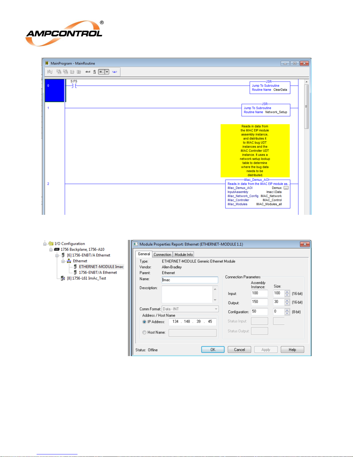
Ampcontrol Pty Ltd – ABN 28 000 915 542
iMAC2 Controller EtherNet/IP Communications Manual
IMAC2B015 V2 – 07/17
APPROVED FOR EXTERNAL DISTRIBUTION – PROPERTY OF AMPCONTROL PTY LTD – NOT TO BE REPRODUCED IN PART
Figure 5: Minimum Program/Routine requirements for getting iMAC2 EtherNet/IP data in RSLogix5000
Figure 6: Generic Ethernet Module setup for iMAC2 EIP data.
If there is a SIM-G, SIM-G2, SIM-P or SIM-T module in the iMAC2 network, this needs setting up in a more
complex way because it takes up 16 consecutive node addresses (or 17 for a SIM-P module). Additional
network configuration data is used to specify the SIM-G/SIM-G2/SIM-P/SIM-T unit number and the subindex of the node within the 16 (or 17) consecutive node addresses. This is better explained with an
example of SIM-G data setup as follows:
IMAC2B015 V2 Uncontrolled Copy - Refer to Ampcontrol Website for Latest Version Page 38 of 41
Page 40
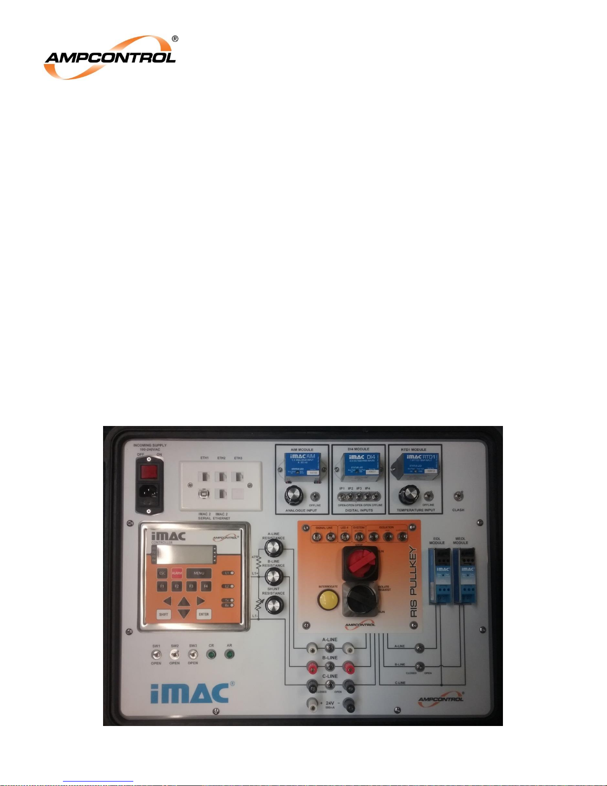
Ampcontrol Pty Ltd – ABN 28 000 915 542
iMAC2 Controller EtherNet/IP Communications Manual
IMAC2B015 V2 – 07/17
APPROVED FOR EXTERNAL DISTRIBUTION – PROPERTY OF AMPCONTROL PTY LTD – NOT TO BE REPRODUCED IN PART
IMAC_Network.Lookup_Table[node address].Module_Type := 37; // SIM-G type
IMAC_Network.Lookup_Table[node address].Module_Type_Data1 := unit_number; //0 to 15
IMAC_Network.Lookup_Table[node address].Module_Type_Data2 := 0;
IMAC_Network.Lookup_Table[node address+1].Module_Type := 37; // SIM-G type
IMAC_Network.Lookup_Table[node address+1].Module_Type_Data1 := unit_number; //0 to 15
IMAC_Network.Lookup_Table[node address+1].Module_Type_Data2 := 1;
IMAC_Network.Lookup_Table[node address+2].Module_Type := 37; // SIM-G type
IMAC_Network.Lookup_Table[node address+2].Module_Type_Data1 := unit_number; //0 to 15
IMAC_Network.Lookup_Table[node address+2].Module_Type_Data2 := 2;
and so on to
IMAC_Network.Lookup_Table[node address+15].Module_Type := 37; // SIM-G type
IMAC_Network.Lookup_Table[node address+15].Module_Type_Data1 := unit_number; //0 to 15
IMAC_Network.Lookup_Table[node address+15].Module_Type_Data2 := 15;
Example Setup 4.4
This example is based on the iMAC2 Demonstration Box shown in Figure 7.
Figure 7: iMAC2 Demonstration Box
IMAC2B015 V2 Uncontrolled Copy - Refer to Ampcontrol Website for Latest Version Page 39 of 41
Page 41
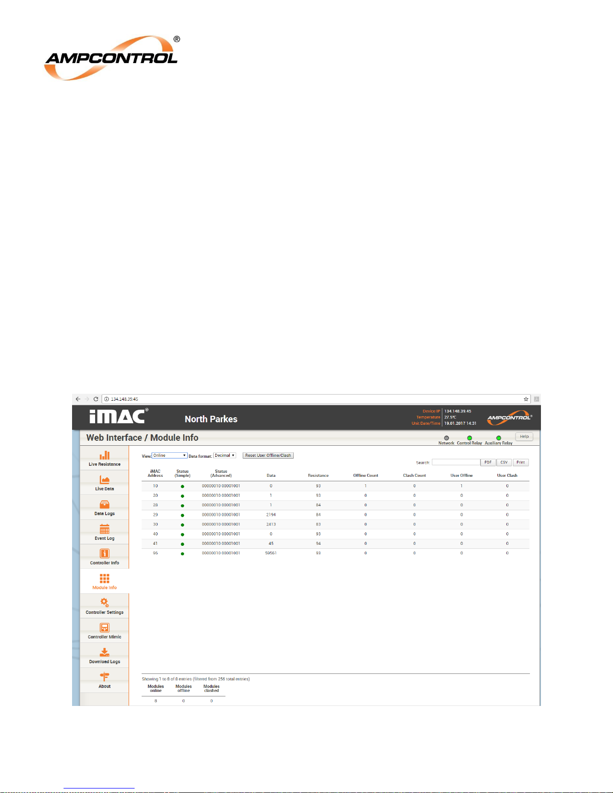
Ampcontrol Pty Ltd – ABN 28 000 915 542
iMAC2 Controller EtherNet/IP Communications Manual
IMAC2B015 V2 – 07/17
APPROVED FOR EXTERNAL DISTRIBUTION – PROPERTY OF AMPCONTROL PTY LTD – NOT TO BE REPRODUCED IN PART
It has three modules – an AIM module, a DI4 module and an RTD1 module. When running, the web
interface shows the online modules as in Figure 8. The modules and addresses are as follows:
iMAC address 10: EOL module.
iMAC address 20: DI4 module.
iMAC address 28: AIM_FLAGS module.
iMAC address 29: AIM_AI module.
iMAC address 30: AIM_Power module.
iMAC address 40: RTD1_FLAGS module.
iMAC address 41: RTD1_Temp module.
iMAC address 96: MEOL module.
In RSLogix5000, this network information is entered as follows:
IMAC_Network.Lookup_Table[20].Module_Type := 15; // DI4 type
IMAC_Network.Lookup_Table[28].Module_Type := 48; // AIM_FLAGS type
IMAC_Network.Lookup_Table[29].Module_Type := 49; // AIM_AI type
IMAC_Network.Lookup_Table[30].Module_Type := 50; // AIM_Power type
IMAC_Network.Lookup_Table[40].Module_Type := 54; // RTD1_FLAGS type
IMAC_Network.Lookup_Table[41].Module_Type := 55; // RTD1_Temp_Input type
Figure 8: iMAC web interface online modules.
IMAC2B015 V2 Uncontrolled Copy - Refer to Ampcontrol Website for Latest Version Page 40 of 41
Page 42
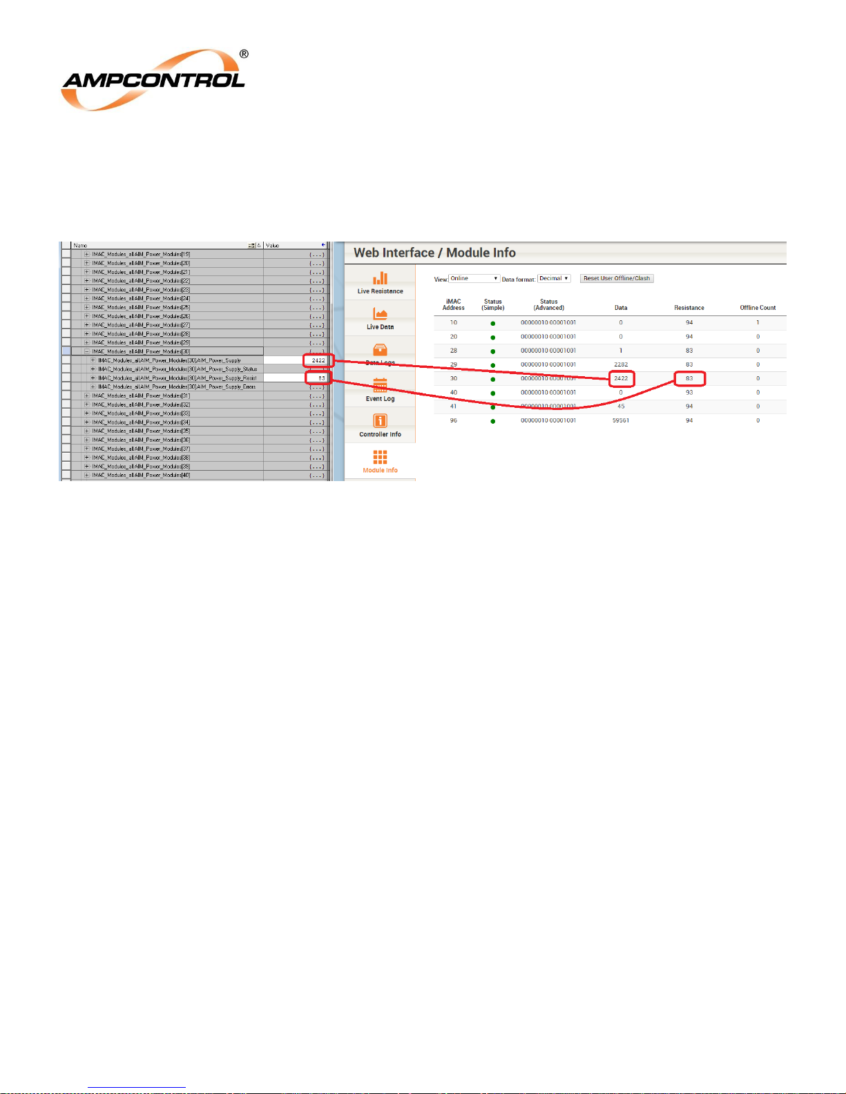
Ampcontrol Pty Ltd – ABN 28 000 915 542
iMAC2 Controller EtherNet/IP Communications Manual
IMAC2B015 V2 – 07/17
APPROVED FOR EXTERNAL DISTRIBUTION – PROPERTY OF AMPCONTROL PTY LTD – NOT TO BE REPRODUCED IN PART
When the PLC code is running, the iMAC2 data will be retrieved from the EIP instance and will be
distributed to the module arrays as needed. For example, the AIM Power module at node address 30 will
have its data inserted into IMAC_Modules_all.AIM_Power_Modules[30] - Figure 9 shows the Power supply
data (24.22V) and resistance value (93 ohms) transferred correctly.
Figure 9: Node 30 data transferred to the PLC.
Once the iMAC2 data is transferred to the PLC correctly, it can easily be referenced and used in the
automation project via aliasing, or via direct tag references such as:
Important_Input_Bool := IMAC_Modules_all.DI8_Modules[7].DI8_Inputs_IP3
IMAC2B015 V2 Uncontrolled Copy - Refer to Ampcontrol Website for Latest Version Page 41 of 41
 Loading...