

Page 1
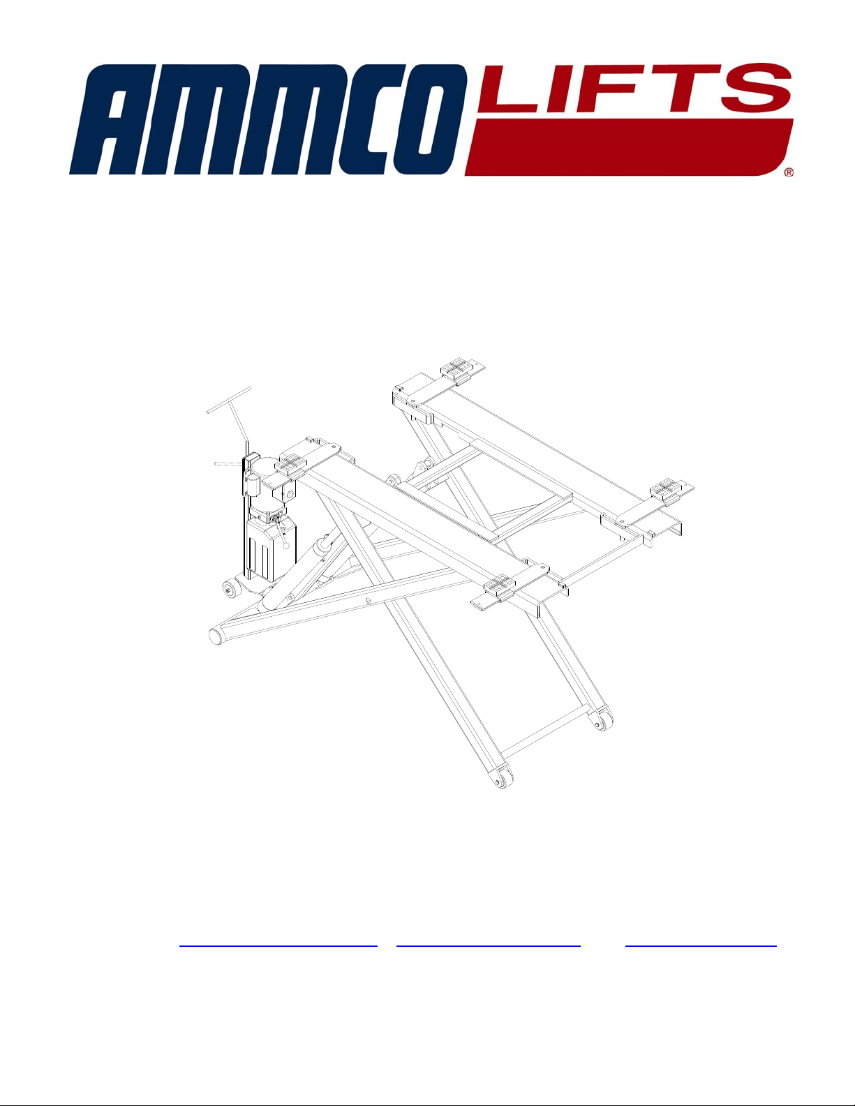
MODEL SM6000
P
ORTABLE MID-RISE LIFT
6,000 lb Capacity – 1500 lb Per Arm
INSTALLATION, OPERATION AND
M
AINTENANCE MANUAL
IMPORTANT!!!
READ THIS MANUAL COMPLETELY BEFORE INSTALLING OR
OPERATING THE LIFT
Hennessy Industries, Inc., 1601 J.P. Hennessy Drive, LaVergne, TN 37086-3565
Email: liftservice@ammcoats.com
& liftsales@ammcoats.com Web: www.ammcoats.com
Office 888-760-LIFT (5438)
12/12/08
Page 2
Model SM6000
Installation, Operation, and Maintenance
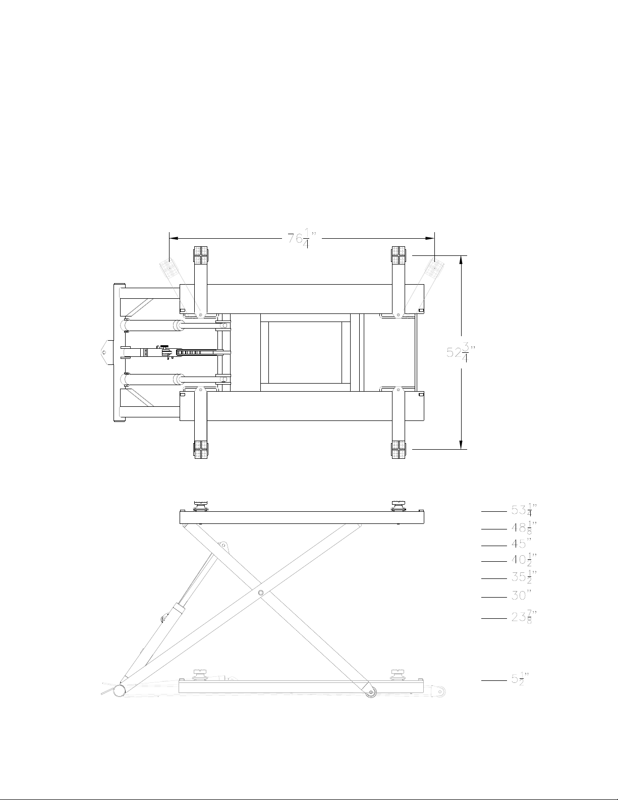
GENERAL SPECIFICATIONS
Maximum Capacity......................................................................................... 6,000 lbs
Minimum Table Height ...............................................................................5 1/2 inches
Maximum Table Height ............................................................................53 1/4 inches
Electrical Requirements .........................................................115V, 50/60 Hz, 1 phase
Lifting Time..................................................................................................45 seconds
Safety Lock ………………………………………………System Mechanical Safety Lock
File: MR6-IOM-E.doc
2 Rev: 12/12/08
Page 3
Model SM6000
Installation, Operation, and Maintenance
Before You Begin
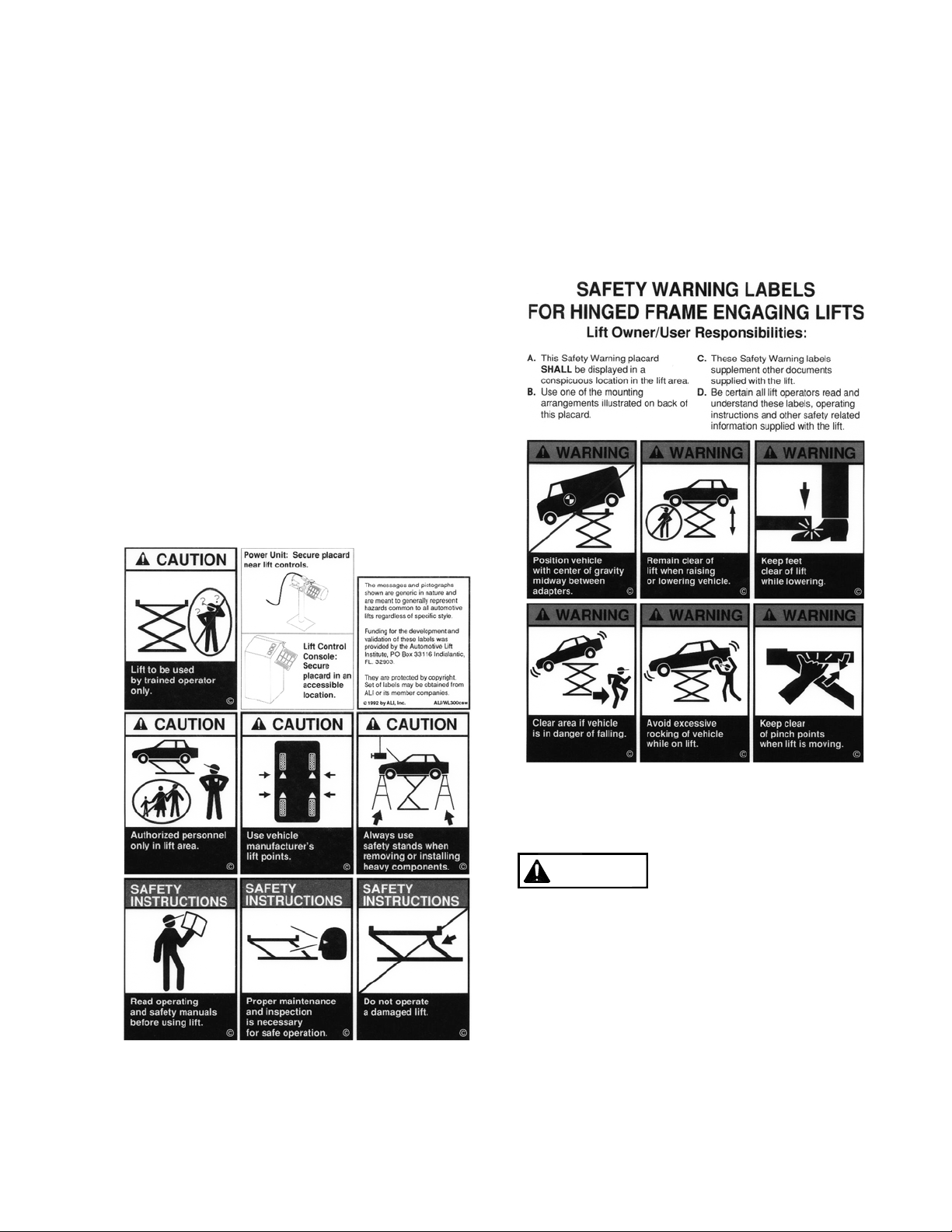
Safety Notices and Decals
For you safety, and the safety of others,
read and understand all of the safety
notices and decals included here.
Read entire manual before
assembling, installing, operating,
or servicing this equipment.
Proper maintenance and
inspection is necessary for
safe operation.
DO NOT operate a damaged lift.
Safety decals similar to those shown here
are found on a properly installed lift. Be
sure that all safety decals have been
correctly installed on the lift. Verify that all
authorized operators know the location of
these decals and fully understand their
meaning. Replace worn, faded, or
damaged decals promptly.
Do not attempt to raise a
WARNING
vehicle on the lift until the lift
has been correctly installed
and adjusted as described in
this manual.
File: MR6-IOM-E.doc
3 Rev: 12/12/08
Page 4

Model SM6000
Installation, Operation, and Maintenance
Receiving
The shipment should be thoroughly inspected as
soon as it is received. The signed bill of lading is
acknowledgement by the carrier of receipt in good
condition of shipment covered by our invoice.
If any of the goods called for on this bill of lading
are shorted or damaged, do not accept them until
the carrier makes a notation on the freight bill of
the shorted or damaged goods. Do this for your
own protection.
NOTIFY Ammco-Lifts AT ONCE if any hidden
loss or damage is discovered after receipt
IT IS DIFFICULT TO COLLECT FOR LOSS OR
DAMAGE AFTER YOU HAVE GIVEN THE
CARRIER A CLEAR RECEIPT.
File your claim with Ammco-Lifts promptly.
Support your claim with copies of the bill of lading,
freight bill, and photographs, if available.
Flooring
Be certain you have the proper concrete floor to
properly handle the loaded lift. Floor should be in
generally good condition with no large cracks,
spalling or deterioration. Minimum requirements for
concrete are 4 inches minimum depth, with steel
reinforcement per local comme rcial practice, 3500
psi, cured for 28 days. Floor should be level within
1/4 inch over the installation area. If these
conditions cannot be met, pads can be poured to
accommodate the lift. Pad must be minimum of 8
ft x 8 ft x 1 ft minimum thickness, 3500 psi steel
reinforced mechanically attached to existing floor.
Failure by purchaser to
WARNING
provide the recommended
mounting surface could
result in unsatisfactory lift
performance, property
damage, or personal injury.
Vertical Clearance
Check the height of the area where the lift is to be
installed. Clearance should be calculated based on
the full raised height of the lift plus the height of the
tallest vehicle you intend to service.
WARNING
Failure by purchaser to
provide adequate
could result in unsatisfactory
lift performance, property
damage, or personal injury.
clearance
Electrical Requirements
For lift installation and operation, it is necessary to
have a dedicated 115V single-phase 60-cycle
circuit with a 20 amp circuit breaker or time delay
fuse.
Tools Required for Installation
1. Wrenches: 7/16, 1/2, 9/16, 5/8, 11/16, 15/16, 1
1/8 inch
2. Ratchet drive with the following sockets: 7/16,
1/2, 9/16, 1 1/8 inch
3. Funnel
4. Adjustable wrenches: 8 and 12 inch
File: MR6-IOM-E.doc
4 Rev: 12/12/08
Page 5

Model SM6000
Installation, Operation, and Maintenance
Installation
1. Locate the lift on a level concrete floor with
adequate space on all sides. Minimum floor
thickness is 4”. Minimum floor strength is 3500 psi.
WARNING DO NOT install on asphalt or other
similar unstable surface.
CAUTION If lift is to be used in a paint booth, the
electrical power unit MUST be mounted outside the
booth.
Power Unit
1. Connect the end of the hydraulic hose with the
90-degree elbow to the pressure port on the
power unit. Tighten securely to prevent
leaking.
NOTE: To avoid damage to the hose, never
run the hose under the lift or in the path of the
automobile tires.
2. Fill the reservoir with 6 quarts clean 10wt anti-
foam, anti-rust hydraulic oil or Dexron III ATF.
DO NOT USE OILS WITH DETERGENTS.
3. Place the open end of the hose into a clean
bucket.
4. Plug power unit cord into a dedicated 115V
single phase 60 cycle circuit with a 25 amp
circuit breaker or time delay fuse
5. Cycle the power unit (2 seconds on, 2 seconds
off) until the hose expels a steady stream of
fluid.
6. Connect the hose to the tee fitting on the lift.
7. Actuate the power unit and raise the lift fully,
then lower the lift to the floor. Repeat 3 to 4
times.
CAUTION The power unit operates at high
pressure.
Raise and lower lift a few times and check hose
and fittings for leaks and tighten if required.
Check for binding, misalignment or damage.
Correct any unusual condition before raising
vehicle.
LOCK RELEASE CABLE
8. Raise the lift until a click is heard; make sure
the lock pawl can pivot freely.
9. Look for the threaded tab on the safety lock
assembly. Back the jam nut off the threaded
coiler and adjust until the slack is removed.
Tighten the lock nut and test the lock release
mechanism 3 or 4 times to ensure proper
function.
File: MR6-IOM-E.doc
DECAL PLACEMENT
10. Center and apply the decal on the side of the
main platform, Fig 1.
Fig 1 – Decal Placement
5 Rev: 12/12/08
Page 6

Owner/Operator Checklist
SAVE THESE INSTRUCTIONS deliver them to
owner/user/employee along with other materials
furnished with this lift.
Demonstrate the operation of the lift to the
owner/operator and review correct and safe lifting
procedures using the Lifting It Right
booklet as a
guide.
Safety Notices and Decals
This product is furnished with graphic safety
warning labels, which are reproduced on page 3 of
these instructions. Do not remove or deface these
warning labels, or allow them to be removed or
defaced. For your safety, and the safety of others,
read and understand all of the safety notices and
decals included.
Owner/Employer
Responsibilities
This lift has been designed and constructed
according to ANSI/ALI ALCTV-1998 standard. The
standard applies to lift manufactures, as well as to
owners and employers. The owner/employer’s
responsibilities as prescribed by ANSI/ALI ALOIM2000, are summarized below. For exact wording
refer to the actual standard provided with this
manual in the literature pack.
The Owner/Employer shall insure that the lift
operators are qualified and that they are trained in
the safe use and operation of the lift using the
manufacturer’s operating instructions; ALI/SM 931, ALI Lifting It Right Safety Manual; ALI/ST-90 ALI
Safety Tips Card; ANSI/ALI ALOIM-2000;
American National Standard for Automotive LiftsSafety Requirements for Operation, Inspection and
Maintenance; ALI/WL Series, ALI Uniform Warning
Label Decals/Placards; and in case of frame
engaging lifts, ALI/LP-GUIDE, Vehicle Lifting
Points/Quick Reference Guide for Frame Engaging
Lifts.
The Owner/Employer shall establish procedures
to periodically inspect the lift in accordance with
the lift manufacturer’s instructions or ANSI/ALOIM2000, American National Standard for Automotive
Lifts-Safety Requirements for Operation,
Inspection and Maintenance; and the employer
shall insure that the lift inspectors are qualified and
they are adequately trained in the inspection of the
lift.
The Owner/Employer shall establish procedures
to periodically maintain the lift in accordance with
the lift manufacturer’s instructions or ANSI/ALOIM2000, American National Standard for Automotive
Lifts-Safety Requirements for Operation,
Inspection and Maintenance; and the employer
shall insure that the lift maintenance personnel are
qualified and they are adequately trained in the
inspection of the lift.
The Owner/Employer shall maintain the periodic
inspection and maintenance records
recommended by the lift manufacturer or
ANSI/ALOIM-2000, American National Standard
for Automotive Lifts-Safety Requirements for
Operation, Inspection and Maintenance.
The Owner/Employer shall display the lift
manufacturer’s operating instructions; ALI/SM 931, ALI Lifting It Right Safety Manual; ALI/ST-90 ALI
Safety Tips Card; ANSI/ALI ALOIM-2000;
American National Standard for Automotive LiftsSafety Requirements for Operation, Inspection and
Maintenance; and in case of frame engaging lift,
ALI/LP-GUIDE, Vehicle Lifting Points/Quick
Reference Guide for Frame Engaging Lifts; in a
conspicuous location in the lift area convenient to
the operator.
IMPORTANT SAFETY
INSTRUCTIONS
When using your garage equipment, basic safety
precautions should always be followed, including
the following:
1. Read all instructions.
2. Care must be taken as burns can occur from
touching hot parts.
3. To reduce the risk of fire, do not operate
equipment in the vicinity of open containers of
flammable liquids (gasoline).
4. Keep hair, loose clothing, fingers, and all parts
of body away from moving parts.
5. Use only as described in this manual. Use
only manufacturer’s recommended
attachments.
6. ALWAYS WEAR SAFETY GLASSES.
Everyday eyeglasses only have impact
resistant lenses, they are not safety glasses.
SAVE THESE INSTRUCTIONS
Operating Instructions
NOTE:
After reviewing these instructions and all decals,
get familiar with lift controls by running the lift
through a few cycles before loading vehicle on lift.
Loading Vehicle
12/12/08
Page 7

Model SM6000
Installation, Operation, and Maintenance
1. Be sure lift is fully lowered and service bay is
clear of all personnel before the vehicle is
driven on to lift.
2. Position vehicle over lift having equal distance
from front tire to end of front ramps and rear
tire to end of rear ramps. Vehicle must also be
centered side to side.
WARNING Lift is designed to raise complete
vehicle. NEVER use to raise just one end or
Side of vehicle.
NOTE:
Some vehicles may have the manufacturer’s
recommended lift points identified by triangle
shape marks located on its undercarriage. Also,
there may be a label located on the right front door
lock face showing specific vehicle lift points.
If the vehicles lift points are not identified,
refer to the service garage lift points shown in Fig.
1. ALWAYS follow the operating instructions
supplied with the lift.
Ladder
Unitized
Perimeter
Stub
Fig 1 Service Garage Lift Points
File: MR6-IOM-E.doc
7 Rev: 12/12/08
Page 8

Installation, Operation, and Maintenance
CAUTION Most specialty or modified vehicles
cannot be raised on a frame engaging or pad
lift. Contact vehicle manufacturer for raising
or jacking details.
3. Before lifting the vehicle be sure that:
A. Individual axle weight of vehicle does not
exceed one-half lift capacity. See safety
instructions (capacity).
B. Vehicle is stable on lift and neither front
nor rear heavy.
CAUTION With some vehicles, the removal
(or installation) of heavy components may
cause a critical shift in balance and result in
vehicle instability. Refer to the vehicle
manufacturer’s service manual for
recommended procedures when performing
these services.
Model SM6000
Raising Vehicle
4. To raise lift:
Lowering Vehicle
5. To lower lift:
6. Before moving vehicle, be sure lift is at the fully
NOTE:
The lock bar will reset automatically when the lift is
fully lowered or raised a minimum of 1”. If during
the lowering process the lift is stopped before it
gets to the fully lowered position. Reset by
repeating steps 5 or 6 from above.
A. Actuate RAISE switch on electric power unit.
B. Raise vehicle until tires clear floor.
C. Check to make sure all four contact pads
are secure on the vehicle.
D. Continue to raise to desired height ONLY if
vehicle is secure on lift.
E. Once you have reached the required height
set into lock by depressing the lowering
handle.
Stand clear of lift and vehicle when
Observe pinch point warning decals.
A. Remove all tools or other objects from lift area.
B. Raise vehicle approximately 1” to
disengage lock.
C. Push LOWERING valve handle to lower lift.
CAUTION Lowering handle must be held
down to continue to lower lift. DO NOT
override self-closing lift controls.
lowered position and is clear of any tools or
objects.
lowering.
File: MR6-IOM-E.doc
8 Rev: 12/12/08
Page 9

Model SM6000
Installation, Operation, and Maintenance
MAINTENANCE
NOTE:
To avoid personal injury, permit only qualified personnel to perform maintenance on this lift.
See repair parts breakdown for replacement parts.
ALWAYS: Keep all bolts tight. Check periodically.
ALWAYS: Keep lift clean. Raise lift when cleaning floor area.
DAILY: Check lock bar handle and release mechanism for damage or binding.
WEEKLY: Inspect all lift parts for signs of damage due to improper use.
MONTHLY: Lubricate lock bar pivot bolt and lock bar handle pivot points.
MONTHLY: Lubricate all hinge joints if there are signs of rusting.
SEMI-ANNUALLY: Check fluid level of lift power unit and refill if required. Use only Dexron III ATF or 10wt
anti-foam, anti-rust hydraulic oil. If fluid is required, inspect hose and connections and cylinder seals. Repair
as required.
File: MR6-IOM-E.doc
9 Rev: 12/12/08
Page 10

Model SM6000
Installation, Operation, and Maintenance
PARTS BREAKDOWN
No
1
2
3
4L
4R
5
6
7
8
9
10
11
12
Part #
GTYJ3-01-00
GTYJ3-03-00
GTYJ3-02-00
GTYJ3-04-00L
GTYJ3-04-00R
GTYJ3-07-00
TYJ3-05-03
MR6-002
TYJ3-05-02
TYJ3-05-01
TYJ3-11-00
TYJ3-12
TYJ3-16
File: MR6-IOM-E.doc
Qty Description No Part # Qty Description
1 Scissor Outside 13
1 Scissor Inside 14
1 Platform 15
1 Cylinder Assy. (Left) 16
1 Cylinder Assy. (Right) 17
1 Safety Locking Assy. 18
4 Plate 19
4 Hex Bolt, M10x20 20
4 Saddle Holder 21
4 Rubber Saddle 22
2 Wheel (Big) 23
2 Wheel Pin (Big) 24
2 Connecting Pin 25
TYJ3-13
TYJ3-08
TYJ3-10
SR-0114
TYJ3-09
TYJ3-15
TYJ3-14-00
X10-020
MR6-003
MR6-004
MR6-005 4 Hex Nut, M20
X10-099 4 Washer, M20
TYJ3-05-02G 4 6 7/8” Extensions
10 Rev: 12/12/08
2 Scissor Pin
1 Safety Locking Pin
(Bottom)
1 Safety Locking Pin (Top)
1 Locking Nut, M18
2 Cylinder Pin
2 Wheel Pin (Small)
2 Wheel (Small)
6 Retaining Ring 20mm
6 Retaining Ring 18mm
4 Retaining Ring 24mm
Page 11

Model SM6000
Installation, Operation, and Maintenance
SAFETY LOCK ASSEMBLY
No.
1
GTYJ3-07-02
2
GTYJ3-07-01
3
TYJ3-07-05
4
5
6
TYJ3-07-04
7
TYJ3-07-06
8
TYJ3-07-03
9
Part #
MR6-006
SR-0112
X10-081
Qty. Description
1 Lock Sheath
1 Lock Pole
1 Base
2 Socket Head Bolt, M8 x 16
2 Washer, M8
1 Pulley Assy.
1 Spring
1 Lock Block
1 Roll Pin 4 x 30
File: MR6-IOM-E.doc
11 Rev: 12/12/08
Page 12

Model SM6000
Installation, Operation, and Maintenance
POWER UNIT STAND / TOW DOLLY
A
SSEMBLY INSTRUCTIONS
No. Part # Qty. Description No. Part # Qty. Description
1 TYJ3-00-01-1 1 Handle 9 MR6-008 4 Lock Washer, M8
2 TYJ3-00-01-2-1 1 Stand 10 MR6-009 4 Hex Bolt, M8x25
3 TYJ3-00-01-2 1 Base 11 SR-0112 4 Washer, M8
4 AB-1563-B 1 Electric/Hyd. Unit
5 TYJ3-00-01-3 2 Wheel 13 4100342 4 Bolt, 5/16”-18 x 1/2"
6 X10-040 2 Nut, M12 14 4100237 4 Nut, 5/16”-18
7 X10-038 4 Washer, M12 15 TYJ3-32 1 Lock Release Handle
8 MR6-007 4 Hex Bolt, M8x20
X10-040 4 Nut, M8
12
File: MR6-IOM-E.doc
12 Rev: 12/12/08
Page 13

Model SM6000
Installation, Operation, and Maintenance
HYDRAULIC/LOCK RELEASE BREAKDOWN
No Part # Qty. Description
1 TYJ3-25 2 Hydraulic Hose Short
2 TYJ3-31 1 Lock Release Cable
3 TYJ3-26 1 Hydraulic Hose Long
4 16167 1 Hyd. Elbow; 9/16-18 O-Ring x 37 deg Male
5 66020 1 ¼ NPTM x #6 JIC 37 deg Female
File: MR6-IOM-E.doc
13 Rev: 12/12/08
 Loading...