AMMCO 700 Vehicle Brake Lathe User Manual

 700/705/710
Vehicle Mounted Brake Lathe &
® Rotor Driving Unit
Installation Instructions
Operating Instructions
Safety Instructions
Maintenance Instructions
READ these instructions before placing unit in service. KEEP these and other materials delivered with the unit in a binder near the machine for ease of reference by supervisors and operators.
1601 J. P. Hennessy Drive, LaVergne, TN USA 37086-3565 615/641-7533 800/688-6359 |
Manual Part No.: |
927588 16 |
HENNESSY INDUSTRIES INC. Manufacturer of AMMCO®, COATS® and BADA® Automotive Service Equipment and Tools. |
Revision: |
06/01 |

Brake Lathes
ii • AMMCO 700/705/710 Brake Lathes

Contents
Table of Contents
Safety Notices and Decals . . . . . . . . . . . . .iv
Warning . . . . . . . . . . . . . . . . . . . . . . . . . . . .iv
Cautions and Dangers . . . . . . . . . . . . . . . . . . . .iv
Owner’s Responsibility . . . . . . . . . . . . . . . .v
Definitions of Hazard Levels . . . . . . . . . . . .v
Important Safety Instructions . . . . . . . . . .vi
Before You Begin
Receiving . . . . . . . . . . . . . . . . . . . . . . . . . . . . . .1
Components
Know Your Unit . . . . . . . . . . . . . . . . . . . . . . . . . .2
Model 700 Vehicle Mounted Brake Lathe . . . . . .2
Model 710 Specifications . . . . . . . . . . . . . . . . . .2
Brake Lathe Operation . . . . . . . . . . . . . . . . .3
Reconditioning Disc Brake Rotors . . . . . . . |
. . . . .3 |
Depth-Of-Cut Micrometer Dials . . . . . . . . . |
. . . . .3 |
Vehicle Preparation . . . . . . . . . . . . . . . . . . |
. . . . .3 |
Lathe Mounting Procedures . . . . . . . . . . . |
. . . . .4 |
Use of Mounting Hardware . . . . . . . . . . . . . |
. . . .5 |
Installation With The Vehicle’s Caliper Bolts |
. . . . .6 |
Installation With Mounting Bolts |
|
Supplied in Mounting Hardware . . . . . . . . . |
. . . .7 |
Set-Up and Machining . . . . . . . . . . . . . . . . |
. .8 - 9 |
Restoring Vehicle . . . . . . . . . . . . . . . . . . . . . |
. . .10 |
Maintenance and Service
Oiling . . . . . . . . . . . . . . . . . . . . . . . . . . . . . . . .10
Cleaning . . . . . . . . . . . . . . . . . . . . . . . . . . . . . .10
Gib Adjustment . . . . . . . . . . . . . . . . . . . . . .10 - 11
Storage . . . . . . . . . . . . . . . . . . . . . . . . . . . . . . .11
Care of Mounting Hardware . . . . . . . . . . . . . . . .11
Installation Of Hardware Storage Rack . . .11
Components
Know Your Unit . . . . . . . . . . . . . . . . . . . . . . . . .12
Model 705 Rotor Driving Unit . . . . . . . . . . . . . .12
Model 710 Specifications . . . . . . . . . . . . . . . . . .12
Electrical Wiring Requirements . . . . . . . . .13
Thermal Overload Circuit Breaker . . . . . . . . . . . .13
Assembly Instructions . . . . . . . . . . . . . . . .13
Mounting of Lug Adapter . . . . . . . . . . . . .14
Rotor Drive Unit Operation . . . . . . . .15 - 16
Maintenance and Service
Oiling . . . . . . . . . . . . . . . . . . . . . . . . . . . . . . . .17
Cleaning . . . . . . . . . . . . . . . . . . . . . . . . . . . . . .17
Care of Adapter . . . . . . . . . . . . . . . . . . . . . . . . .17
Storage . . . . . . . . . . . . . . . . . . . . . . . . . . . . . . .17
Pivot Adjustment . . . . . . . . . . . . . . . . . . . . . . . .17
AMMCO 700/705/710 Brake Lathes • iii

Safety
Safety Notices and
Decals
For your safety, and the safety of others, read and understand all of the safety notices and decals included here and on the unit.
Read entire manual before installing, operating, or servicing this equipment.
Proper maintenance and inspection is necessary for safe operation.
Do not operate a damaged lathe.
Warning
This equipment incorporates parts such as snap switches and power receptacles which tend to produce arcs or sparks. Therefore, when located in a service facility, the unit should be in a room or enclosure provided for the purpose, or should be at least 18” or more above floor to minimize the risk of igniting fuel vapors.
Cautions and Dangers
1.Eye and face protection requirements:
“Protective eye and face equipment is required to be used where there is a reasonable probability of injury that can be prevented by use of such equipment.” OSHA 1910.133 (a).
Protective goggles, safety glasses, or a face shield must be provided by the purchaser/user and worn by the operator of the equipment. Make sure all eye and face safety precautions are followed by the operator(s). Keep bystanders out of the area.
2.Do not remove any safety equipment, belt guards, or shortcut controls or operations.
3.Make sure drums and rotors are properly and squarely mounted before starting lathe, and that all parts are secure.
4.Do not wear loose clothing, jewelry, or gloves when operating or working around a lathe.
5.Do not overload the lathe. Read and understand the lathe specifications. Overloading is poor machine tool practice, shortens the life of the lathe, and could cause a failure resulting in personal injury.

 WARNING
Failure to follow danger, warning, and caution instructions may lead to serious personal injury or death to operator or bystander or damage to property. Do not operate this machine until you read and understand all the dangers, warnings and cautions in this manual. For additional copies of either, or further information, contact:
Hennessy Industries, Inc.
1601 J.P. Hennessy Drive
LaVergne, TN 37086-3565
(615) 641-7533 or (800) 688-6359 www.Hennessy-Ind.com
iv • AMMCO 700/705/710 Brake Lathes

Safety
Owner’s Responsibility
To maintain machine and user safety, the responsibility of the owner is to read and follow these instructions:
•Follow all installation instructions.
•Make sure installation conforms to all applicable Local, State, and Federal Codes, Rules, and Regulations; such as State and Federal OSHA Regulations and Electrical Codes.
•Carefully check the unit for correct initial function.
•Read and follow the safety instructions. Keep them readily available for machine operators.
•Make certain all operators are properly trained, know how to safely and correctly operate the unit, and are properly supervised.
•Allow unit operation only with all parts in place and operating safely.
•Carefully inspect the unit on a regular basis and perform all maintenance as required.
•Service and maintain the unit only with authorized or approved replacement parts.
•Keep all instructions permanently with the unit and all decals/labels/notices on the unit clean and visible.
•Do not override safety features.
 CAUTION
Prevent accidents and injury, read and follow instructions.
1.Read and follow instructions.
2.Always wear eye protection, avoid loose clothing and jewelry.
3.Keep all guards, shields, and covers in place and in working order.
4.Keep bystanders out of work area.
5.Unplug unit from power source before servicing or adjusting.
6.Maintain unit properly, keep work surfaces and work area clean.
Definitions of Hazard
Levels
Identify the hazard levels used in this manual with the following definitions and signal words:
DANGER
Watch for this symbol:

 DANGER
It Means: Immediate hazards, which will result in severe personal injury or death.
WARNING
Watch for this symbol:
 WARNING
It Means: Hazards or unsafe practices, which could result in severe personal injury or death.
CAUTION
Watch for this symbol:

 CAUTION
It Means: Hazards or unsafe practices, which may result in minor personal injury or product or property damage.
Watch for this symbol! It means BE ALERT! Your safety, or the safety of others, is involved!
AMMCO 700/705/710 Brake Lathes • v

IMPORTANT SAFETY INSTRUCTIONS
Before operating the lathe, review the warning information on the lathe and the cautions, warnings and dangers in this manual. Also review the following general safety instructions. Failure to follow safety instructions could result in personal injury to operator or bystanders and damage to the lathe or personal property.
READ ALL INSTRUCTIONS
When using your garage equipment, basic safety precautions should always be followed, including the following:
1.Keep guards in place and in working order.
2.Remove adjusting keys and wrenches from the tool before turning it on. Make this a habit.
3.Keep work area clean and well lighted. Cluttered areas and benches invite accidents.
4.To reduce the risk of fire, do not operate equipment in the vicinity of open containers of flammable liquids (gasoline).
5.Adequate ventilation should be provided when working on operating internal combustion engines.
6.Care must be taken as burns can occur from touching hot parts.
7.Do not operate equipment with a damaged cord or if the equipment has been dropped or damaged—until it has been examined by a qualified serviceman.
8.If an extension cord is necessary, a cord with a current rating equal to or more than that of the equipment should be used. Cords rated for less current than the equipment may overheat. Care should be taken to arrange the cord so that it will not be tripped over or pulled.
9.To reduce the risk of electric shock, do not use on wet surfaces or expose to rain.
10.Keep children away. All bystanders should be kept completely away from the work area.
11.Make the workshop kid-proof. Use padlocks and master switches, and remove starter keys.
12.Don’t force a tool. It will do the job better and safer at the rate for which it was designed.
13.Use the right tool. Don’t force a tool or an attachment to do a job for which it was not designed.
14.Dress properly. Keep hair, loose clothing, neckties, shop rags, jewelry, fingers, and all parts of body away from moving parts. Non-slip footwear is recommended.
15.ALWAYS WEAR SAFETY GLASSES. Everyday eyeglasses only have impact resistant lenses, they are NOT safety glasses. Safety glasses, goggles, or a face shield will help protect the operator from injury. Use a face shield and dust mask during dusty operations.
16.Secure the work properly to the unit for setup and tool bit positioning. Do not attempt to hold a drum or rotor steady on the arbor with your hands. Both hands must be free to operate unit.
17.Don’t overreach. Keep proper footing and balance at all times when lathe is in operation or when working around the unit.
18.Maintain tools with care. Keep tools sharp and clean for best and safest performance. Follow instructions for lubricating and changing accessories.
19.Remove power from the unit and disconnect tools before servicing and when changing accessories such as blades, bits, cutters, etc. Follow lock-out and tag-out procedures as required.
20.Avoid unintentional starting. Make sure the switch is in the OFF (O) position before plugging the machine in or performing any maintenance or service work.
21. Use of improper accessories may cause risk of injury to operator or bystanders. Use only as described in this manual. Use only manufacturer’s recommended attachments.
22.Never stand or lean on a lathe. Serious injury could occur if the lathe is tipped or if the cutting tool is unintentionally contacted.
23.Check damaged parts carefully. Before further use of the lathe, a guard or other part that is damaged should be carefully checked. Immediately replace all damaged, missing, or non-functional parts. Check for alignment of moving parts, binding of moving parts, breakage of parts, mounting, and any other conditions that may affect operation. Guards and other parts that are damaged should be properly repaired or replaced before lathe is used again.
24.Always feed the work into a blade or cutter and against the direction of rotation. Cutters and tool bits are designed to cut from the inside of a drum or rotor to the outer edge. Do not attempt to cut from the outside edge in to the center.
25.Never leave tools running unattended. Turn the power off. Don’t leave the tool until it comes to a complete stop.
26.Never use compressed air to blow the tool clean. Chips and dust may be driven between machined parts and into bearings, causing undue wear. They may also contact persons in the area causing personal injury.
27.Operate the lathe in the proper environment. The lathe incorporates parts such as snap switches and power receptacles which tend to produce arcs or sparks. Therefore, when located in a garage,the unit should be in a room or enclosure provided for the purpose, or should be at least 18” or more above the floor to minimize the risk of igniting fuel vapors.
SAVE THESE INSTRUCTIONS
vi • AMMCO 700/705/710 Brake Lathes

Brake Lathes
Before You Begin
Receiving
The shipment should be thoroughly inspected as soon as it is received. The signed bill of lading is acknowledgement by the carrier of receipt in good condition of shipment covered by our invoice.
If any of the goods called for on this bill of lading are shorted or damaged, do not accept them until the carrier makes a notation on the freight bill of the shorted or damaged goods. Do this for your own protection.
NOTIFY THE CARRIER AT ONCE if any hidden loss or damage is discovered after receipt and request the carrier to make an inspection. If the carrier will not do so, prepare a signed statement to the effect that you have notified the carrier (on a specific date) and that the carrier has failed to comply with your request.
IT IS DIFFICULT TO COLLECT FOR LOSS OR DAMAGE AFTER
YOU HAVE GIVEN THE CARRIER A CLEAR RECEIPT.
File your claim with the carrier promptly. Support your claim with copies of the bill of lading, freight bill, invoice, and photographs, if available.
Although AMMCO’s responsibility ceases upon delivery of the shipment to the carrier, we will gladly assist in tracing lost shipments. Our willingness to assist in every possible manner does not make AMMCO responsible for collection of claims or replacement of lost or damaged materials. Shipping damage claims will not be handled under warranty.
AMMCO 700/705/710 Brake Lathes • 1

Brake Lathes
Components
Know Your Unit
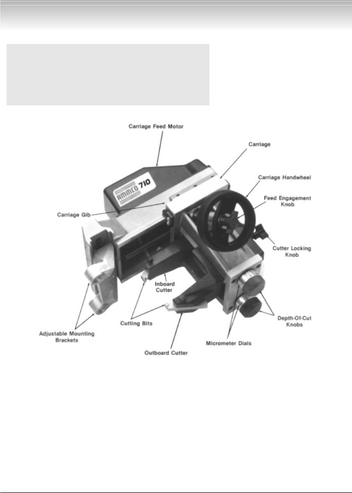
Compare this illustration with the unit before placing it into service. Maximum performance and safety will be obtained only when all persons using the unit are fully trained in its parts and operation. Each user should learn the function and location of all controls. Prevent accidents and injuries by ensuring the unit is properly installed, operated, and maintained.
Model 700 Vehicle Mounted Brake Lathe
Model 710 Specifications
Overall Lathe Height . . . . . . . . . . . . . . . . . . . . . . . . . . . . .9-3/8 in. (238 mm)
Overall Lathe Depth . . . . . . . . . . . . . . . . . . . . . . . . . . .12-11/16 in. (322 mm)
Overall Lathe Width . . . . . . . . . . . . . . . . . . . |
. . . . . . . .11-13/16 in. (300 mm) |
Feed Rate (With Rotor Driving Unit Only/180 RPM) . . . . .. |
0023 in. per rev. (.058 mm/rev.) |
Micrometer Graduations . . . . . . . . . . . . . . . . |
. . . . . ..002 in. (.0508 mm/rev.) |
Max. Distance Between Adjustable Mounting Brackets . . . . .8-1/32 in. (204)
Min. Distance BetweenAdjustable Mounting Brackets . . . .1-1/16 in. (27 mm)
Lathe Weight (Lathe Only) . . . . . . . . . . . . . . . . . . . . . . . . . . . . . 18 lbs. {8.17 kg)
Floor Space . . . . . . . . . . . . . . . . . . . . . . . . . . .15-3/4 in. wide X 10-1/2 in. deep (When Stored in Case) . . . . . . . . . . . . . . . . . . . . . . . .(400 mm X 267 mm)
2 • AMMCO 700/705/710 Brake Lathes
 Loading...