

Page 1

AAsssseemmbbllyy IInnssttrruuccttiioonnss
wwiitthh PPaarrttss IIddeennttiiffiiccaattiioonn
READ these instructions before placing unit in
service. KEEP these and other materials delivered
with the unit in a binder near the machine for
ease of reference by supervisors and operators.
941055 Brake Lathe Toolbox
941054 Side Storage Cabinet
941053 Lighted Toolboard
®
1601 J. P. Hennessy Drive, LaVergne, TN USA 37086 615/641-7533 800/688-6359 Manual Part No.: 341205 00
HENNESSY INDUSTRIES INC. Manufacturer of AMMCO
®
, COATS®and BADA®Automotive Service Equipment and Tools. Revision: 07/02
Page 2
2 • AMMCO
BBrraakkee LLaatthheess
WWhheenn YYoouu RReecceeiivvee
YYoouurr CCaabbiinneett
Unpack the cabinet parts and check them against the
parts list on the last page of this manual. Make sure
you have all the parts listed – and the quantities listed.
Report any shortages immediately.
##994411005555 BBrraakkee LLaatthhee
TToooollbbooxx
Preparing the Bench for Use
1. Carefully lay the bench on its side.
2. Screw a leveling foot into the threaded hole
located at each corner of the bench (4 locations).
3. Once the bench is placed in its final location, level
the bench by raising or lowering the 4 leveling feet as
necessary.
4. Insert a plastic cap in all of the bench top holes
that will not be used for your lathe.
5. Attach lathe to bench.
6. Attach the funnel to the 2 holes in the top of the
left end panel. Use 2 truss head screws.
Figure – Attach Funnel
7. Place drawer liners in the four drawers.
##994411005544 SSiiddee SSttoorraaggee
CCaabbiinneett
Preparing the Cabinet for Use
1. Carefully lay the cabinet on its side.
2. Screw a leveling foot into the threaded hole
located at each corner of the cabinet (4 locations).
3. Once the cabinet is placed in its final location, level
it by raising or lowering the 4 leveling feet as necessary.
4. Place mat on top of cabinet.
5. Place drawer liners in the four drawers.
##994411005533 TTooooll BBooaarrdd aanndd
LLiigghhtt CCaannooppyy
Attaching the Tool Board and Light Canopy
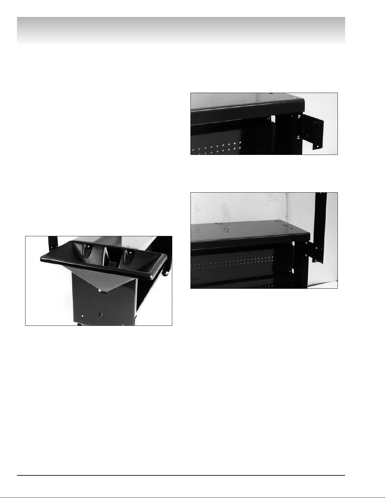
1. Use 3 truss head screws to attach each bracket to
the rear of cabinet. Wrench tighten.
Figure – Attach Brackets to Cabinet
2. Use 3 truss head screws and 3 flange nuts to
attach an upright to the bracket. Wrench tighten the
nuts. Repeat for the other bracket and upright.
Figure 2 – Attach Uprights to Brackets
3. Attach left-hand and right-hand canopy gussets to
the sides of the uprights using two truss head screws
and nuts for each. Wrench tighten.
4. Position the upper tool board behind the front
flanges of the uprights with the tool board flange on the
top and facing the rear. Secure the tool board to the
holes in the uprights with truss head screws and nuts.
Hand tighten the nuts only.
5. Fasten light fixture to light panel using screws and
nuts supplied with the light. Note that the light attaches
to the side of the light panel that has the front edge
formed down.
6. Lay light fixture panel assembly on top of gussets
with the formed edge pointing downwards at front of
cabinet. Secure panel to gussets with four truss head
screws and nuts.
7. Fasten the sign to the front of the light canopy
with two truss head screws and nuts.
8. Wrench tighten all hardware.
Page 3

AMMCO • 3
PPaarrttss IIddeennttiiffiiccaattiioonn
Quantity
Item Part 941055 941054 941053 Description
1 940062 4 4 -- Adjustable Foot
2 923749 1 -- -- Chip Bucket
3 923748 1 -- -- Chip Funnel
4 924100 2 -- 28 1/4-20 x 3/4 Truss Head Screw
5 940055 -- -- 1 Tool Board, Short
6 924557 -- -- 22 1/4-20 Hex Flange Serrated Face Nut
7 925255 -- -- 1 Sign
8 941178 -- -- 2 Upright
9 941182 -- -- 2 Bracket
10 ******
Not Available Separately Base Weldment
11 941179 -- -- 1 Canopy Gusset, LH
12 941180 -- -- 1 Light Mounting Fixture
13 941181 -- -- 1 Light Fixture
14 941188 1 Canopy Gusset, RH
* 909966 -- -- 15 Storage Hook
* 941186 8 -- -- Top Shelf Cap
* 941185 4 -- -- 1/16" Black Drawer Liner
* 941184 -- 4 -- 1/16" Black Drawer Liner
* 941183 -- 1 -- Top Shelf Protector
*Not Shown
BBrraakkee LLaatthheess
14
13
12
11
10
10
9
8
8
7
6
5
4
3
2
1
1
Page 4

341205 00 07/02 © Copyright 2002 Hennessy Industries and AMMCO All Rights Reserved Printed in USA
 Loading...