

Page 1
No. 908500
90850050
Brake Drum Micrometer
Operating Instructions and
Parts Identification
AMMCO Tools, Inc. • Hennessy Industries • 1601 J.P. Hennessy Drive, LaVergne, TN 37086-3565
(800) 688-6359 • (615) 641-7533 • (615) 641-5104 FAX
8500 8500-50
Unit of Measure Inch Metric
Drum Diameter 6" to 16.125" 15 cm to 41 cm
Scale Graduations .001" .1 mm
(Increments)
Graduated Shaft 1" and .125" 1 cm and 2 mm
Optional Shaft 16" – 26" 39 cm – 66 cm
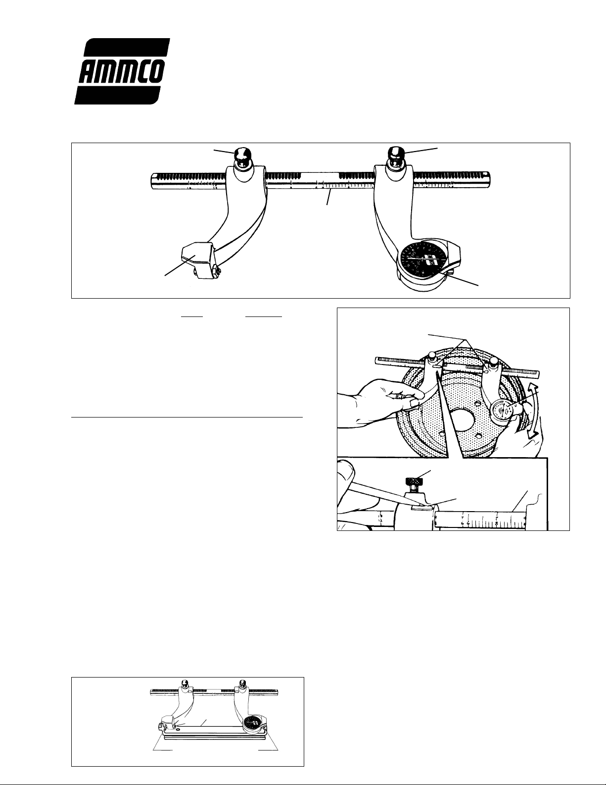
Measuring the Drum (Figure 2)
1. Loosen 2 lock screws and move both dial and
anvil along the shaft until the “whole” number of
the drum diameter is visible at each arrow.
NOTE: Metric shafts have even numbers on one
side, odd on the other. Inch shafts have identical
scales.
2. Place micrometer inside the drum across the
greatest diameter to be measured. Hold anvil
steady and move dial back and forth against the
braking surface to obtain the highest reading.
Calibration (Figure 3)
The micrometer is calibrated at the factory. Check
the calibration using a No. 909582 Checking Gauge
or a standard outside micrometer. To recalibrate,
loosen the jam nut (#22) and adjust set screw (#21)
until the correct reading is obtained. Tighten jam nut
while holding set screw stationary.
Drum Condition
Drums should always be carefully inspected for
cracks, worn or loose bearing races, scoring, heat
checks taper, bell-mouth, and out-of-roundness.
Drum out-of-round conditions are checked by taking
micrometer readings at 2 or more positions around
the drum. Scoring, out-of-roundness, bell-mouth,
and taper should be corrected by machining.
Correcting most of the above conditions will require
cutting material from the drum wall. If the drum
diameter after machining is larger than the
manufacturer’s specified rebore limit it must be
replaced.
Drums that are too thin are apt to be weak and
springy, and will not dissipate heat well, resulting in
a loss of braking power. Defective drums should be
scrapped.
Graduated Shaft
Lock Screw
Dial
Anvil
Lock Screw
Arrows for
Reading Scale
Dial
Lock Screw
Arrow
Scale
Figure 1 - Basic Parts Identification
11.000" Standard
27.94 cm Metric Equiv.
No. 909582
Gauge
28
29
Figure 3 Calibration
Figure 2 - Measuring the Drum
Page 2
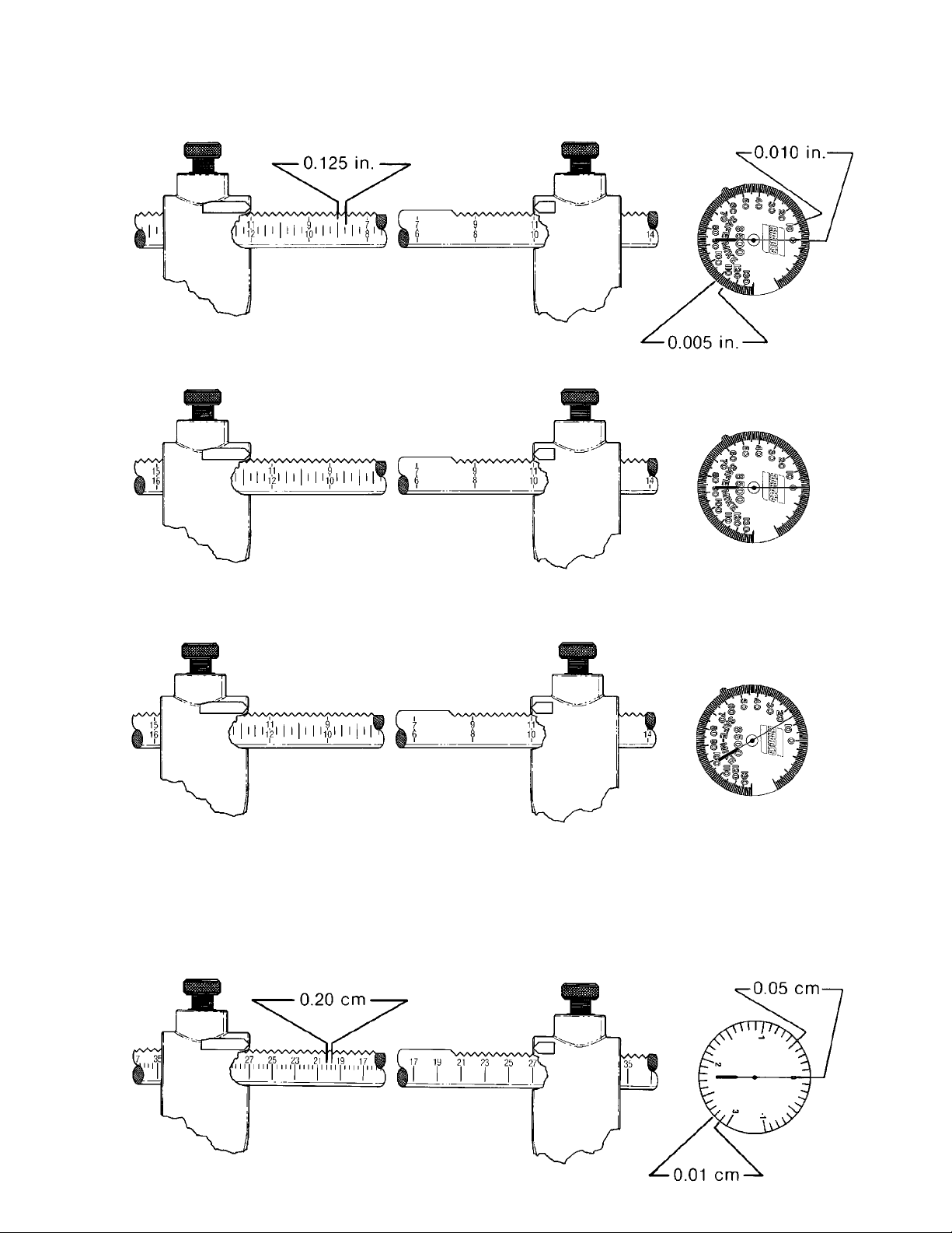
11.000 in.
Diameter
11.375 in.
Diameter
METRIC
INCH
(Examples For Reading The Inch Micrometer)
11.390 in.
Diameter
27.00 cm
Diameter
11.000 in. + 0.375 in. + 0.015 in. = 11.390 in.
11.000 in. + 0.375 in. = 11.375 in.
11.000 in.
27.00 cm
Page 3

METRIC (Examples For Reading The Metric Micrometer)
27.23 cm
Diameter
27.72 cm
Diameter
27.12 cm
Diameter
27.60 cm
Diameter
27.00 cm + 0.60 cm = 27.60 cm
27.00 cm + 0.12 cm = 27.12 cm
27.00 cm + 0.60 cm + 0.12 cm = 27.72 cm
27.00 cm + 0.20 cm + 0.03 cm = 27.23 cm
27.00 cm + 0.23 cm = 27.23 cm
Page 4

908532 10 08/02 © COPYRIGHT 1994 HENNESSY INDUSTRIES AND AMMCO TOOLS ALL RIGHTS RESERVED PRINTED IN U.S.A.
PART
ITEM NO. QTY DESCRIPTION
1 908515 1 Indicator Body
2 * 1 Driving Gear Segment
3 * 1 Shoulder Stud
4 * 1 Dowel Pin
5 909968 * 1 Intermediate Pinion & Gear
6 * 1 Retaining Ring
7 * 1 Groove Pin
8 * 1 Backlash Spring
9 908507 1 Inch Dial Assembly (0.005)
908507C 1 Inch Dial Assembly (0.001)
908508 1 Metric Dial Assembly
10 908528 * 1 Crystal
11 * 1 Retaining Ring
12 * 1 Plunger
13 * 1 Retaining Ring
14 * 1 Plunger Spring
15 * 1 Plug
16 * 1 Retaining Ring
17 909994 2 Plunger Screw Assembly
18 909879 2 Locating Screw
19 903528 2 Jam Nut, 1/4-20 Hex
20 908530 1 Anvil Arm
21 906844 1 Screw, 3/8-24x1 Hex Skt. Hd.
22 906509 1 Jam Nut, 3/8-24 Hex
23 908531
1
1 Shaft, Inch Grad., 6"-16-1/8"
908539
1
Opt. Shaft, Inch Grad., 16"-26"
908541
2
1 Shaft, Metric Grad., 15cm-41cm
90853950
2
Opt. Shaft, Metric Grad., 39cm-66cm
24 908502 1 Body Assembly, Inch (0.005)
908502C 1 Body Assembly, Inch (0.001)
90850250 1 Body Assembly, Metric
NOTES:
* Denotes part included in repair kit (part no. 929935).
1
Shaft for 908500 inch graduated micrometer
2
Shaft for 90850050 metric graduated micrometer
10
11
14
13
12
15
16
17
17
9
18
19
20
21
22
18
19
23
24
3
1
2
4
5
7
8
6
 Loading...