

Page 1
1601 J. P. Hennessy Drive, LaVergne, TN USA 37086-3565 615/641-7533 800/688-6359 Manual Part No.: 925979 09
HENNESSY INDUSTRIES INC. Manufacturer of AMMCO
®
, COATS®and BADA®Automotive Service Equipment and Tools. Revision: 11/02
7900
Twin Cutter
Tool
®
Operating Instructions
with Parts Identification
READ these instructions before placing unit in
service. KEEP these and other materials delivered
with the unit in a binder near the machine for
ease of reference by supervisors and operators.
Page 2

2 • AMMCO 7900 Twin Cutter Tool
Twin Cutter Tool
Page 3
AMMCO 7900 Twin Cutter Tool • 3
The No. 907900 Twin Cutter mounts on the cross
feed tool post to resurface both rotor faces simultaneously. Each tool bar is individually adjustable (in
thousandths of an inch or millimeters) to permit precise depth-of-cut settings, Fig.1.
Installation
1. Remove the nut and self-aligning washers retaining the boring bar. (Older lathes have a tool post pivot
screw which must be loose before the lower clamp
can be removed.)
2. Place the tool bar support over the cross feed
tool post stud and replace self-aligning washers and
nut. (If the lathe has a recess in the top of the tool
post, the chip plate supplied with the twin cutter
should be placed on the tool post before installing the
twin cutter.)
3. Align the tool bar support parallel with the arbor
and wrench tighten the nut.
Reconditioning Disc Brake Rotors
Each brake rotor should be carefully inspected for
SCORING and RUST RIDGES (at the inner and outer
circumference of the rotor). Any excessive wear or
deformity should be noted and, if not within acceptable limits, the rotor should be replaced.
Use a micrometer to check the thickness of the rotor
at no less than three points around circumference
about 1" (2.54 cm) in from the outer diameter. If the
rotor thickness varies between readings, it should be
machined; however, if the thickness is less than the
minimum established by the car manufacturer (or if it
will be less after reconditioning), the rotor should be
replaced. Note: Most often the discard thickness
dimension is cast into the rotor, not the minimum
“machine to” thickness.
The tool bars mount on top of the tool bar support,
carbide bits up, and are used to recondition both brake
surfaces of a rotor at the same time.
Rotor Mounting
Use the cross feed handwheel to move the tool bar
support away from the arbor to permit mounting the
rotor. Mount the rotor on the arbor using the appropriate adapters. Hubbed rotors are mounted on
adapters that fit into the bearing races. Hubless rotors
use a spring loaded cone in the center hole and a hubless adapter on each side of the rotor. Spacers are
used to fill out the arbor shaft so that the arbor nut can
be tightened. The adapters, cones, and spacers supplied with your lathe will allow you to recondition the
majority of rotors on today's vehicles. Optional
adapters, cones, and spacers are available to meet
special needs.
Note: Adapters may also be used as spacers to fill
out the arbor if care is taken to prevent damage to
their machined surfaces.
The patented self-aligning spacer prevents diagonal
thrust on the adapters. The self-aligning spacer should
always be used adjacent to the arbor nut.
Set-Up and Machining
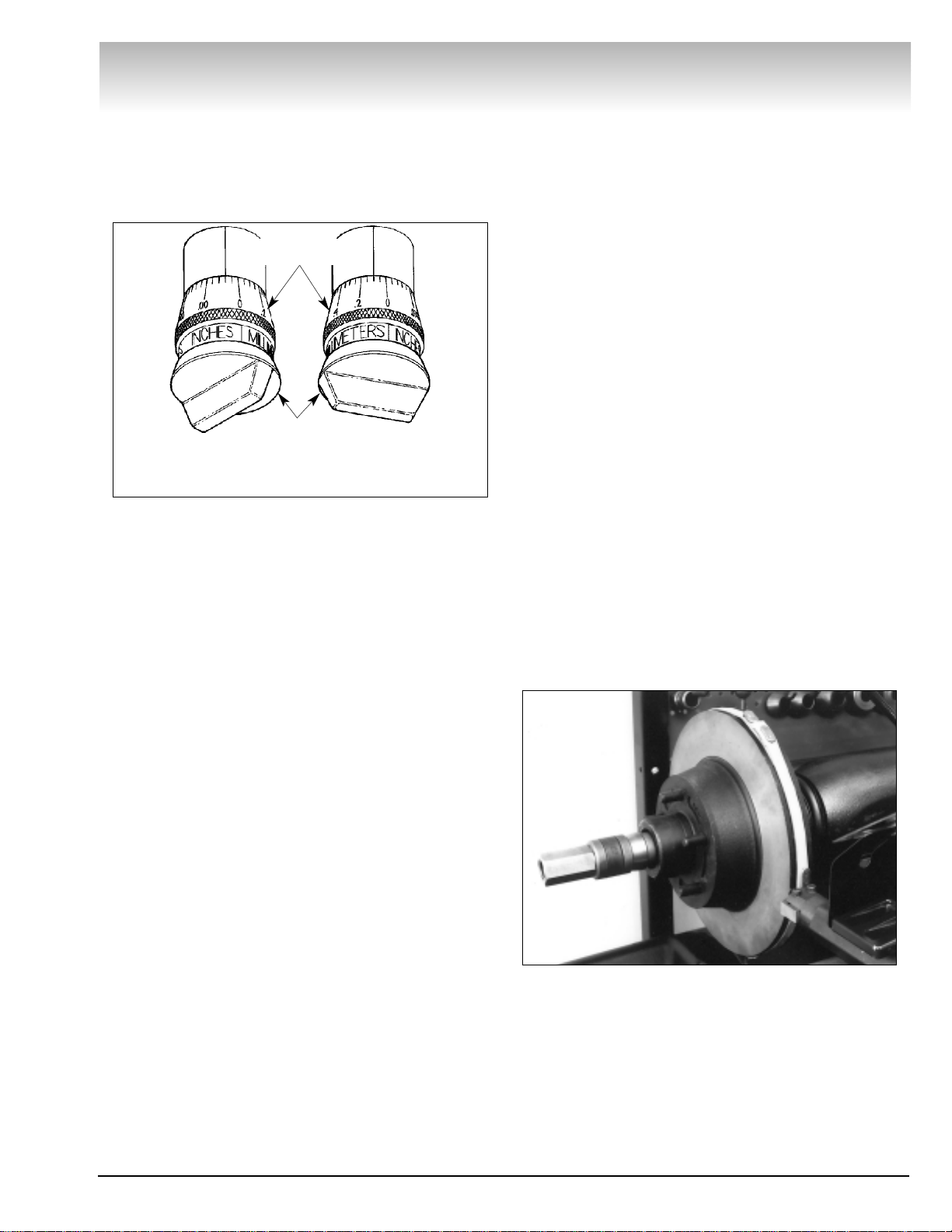
1. Install either a weighted silencer band (vented
rotors), Fig. 2, or a non-weighted silencer band (nonvented rotors), or an optional friction rotor silencer to
dampen vibrations during machining.
2. Use the cross feed handwheel to position the
tool bar support about 1/2" from the rotor or silencer
band. Loosen the tool post nut to center the tool bar
support to the rotor. Wrench tighten the nut. If the tool
bar support cannot be centered with the rotor by moving the tool bar support, it may be necessary to move
the tool bar support, it may be necessary to move the
rotor in or out by using the spindle feed handwheel
Twin Cutter Tool
Figure 2
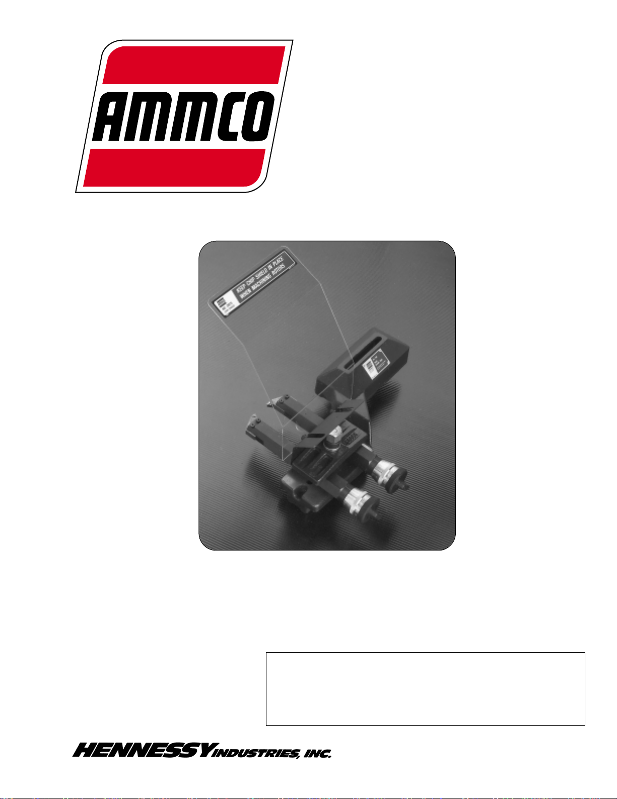
With the lathe on, turn the adjustment knob until the tool bit
lightly contacts the rotor face. Turn the micrometer dial to
zero. Turn the adjustment knob to set the desired depth-of-cut.
Dial Set To
.004 "
Inch/Millimeter
Micrometer Dials
Dial Set To
0.1 mm
Adjustment
Knob
Figure 1
Page 4

4 • AMMCO 7900 Twin Cutter Tool
Twin Cutter Tool
(except Model 7000 Disc Lathe) to make the adjustment.
3. Install the tool bar, carbide tool bit up, on the right
side of the rotor slide with the T-bolt and clamp. Slide
the tool bar into the clamp. Mount the other tool bar,
carbide tool bit up, on the left side of the rotor slide.
4. Turn the end knob of each tool bar micrometer
counterclockwise to fully withdraw the tool bit holders.
5. Position the left tool bar approximately parallel to
the outer brake surface so the tool bit is 1/8" away
from the brake surface and reaches to the groove at
the base of the brake surface. Tighten the T-bolt nut.
Position the right tool bar approximately parallel to the
inner brake surface so its tool bit is directly across
from the left tool bar tool bit and about 1/8" from the
inner brake surface, Fig. 3. Tighten the T-bolt nut.
6. Turn the cross feed handwheel counterclockwise
until the tool bits are about 1/2" in from the outer edge
of the brake surface.
7. Turn the end knob of the left boring bar micrometer clockwise to advance the tool bit until if lightly contacts the outer brake surface making a “scratch cut”
approximately .001" deep. Turn the lathe off.
8. If the tool bit did not scratch the brake surface all
the way around, there is runout in the rotor and/or
runout caused by improper rotor mounting.
9. Use the “scratch cut” method as outlined in
steps 9A, 9B, 9C, and 9D to determine if the runout is
caused by an improper mounting.
9A. Turn the end knob of the left tool bar micrometer
counterclockwise one (1) full turn to back the tool bit
away from the brake surface.
9B. Turn the rotor slide handwheel clockwise to
move the tool bit 1/4" toward the arbor.
9C. Loosen the arbor nut and rotate the rotor 180˚ on
the adapters (do not allow the adapters to turn on the
arbor). Retighten the arbor nut.
9D. Turn the lathe on, then turn the end knob of the
left tool bar micrometer clockwise until the tool bit
makes light contact with the brake surface. Turn the
end knob of the left tool bar micrometer counterclockwise to withdraw the tool bit from the brake surface.
10. Turn the lathe off. If the two scratch cuts are
side by side, Fig. 4, the runout is in the rotor and NOT
in the mounting, continue with step 11. If the two
scratch cuts are 180˚ apart, the runout is caused by an
improper mounting. In this case, inspect the mounting
for cleanliness and the adapters for burrs, nicks, and
scratches as well as the bearing races for looseness.
Remount the rotor and check for runout again. If the
runout has been corrected, proceed with step 11.
11. Turn the lathe on. Turn the end knob of the left
tool bar micrometer clockwise until the tool bit lightly
contacts the brake surface. Hold the end knob of the
micrometer still and rotate the depth-of-cut dial to
zero.
12. Turn the end knob of the right tool bar micrometer clockwise until it lightly contacts the brake surface. Hold the end knob of the micrometer still and
rotate the depth-of-cut collar to zero.
Note: Once you have zeroed a depth-of-cut collar,
use only the end knob to advance or withdraw the tool
bit. The collar will rotate with the knob to show the
depth-of-cut. Any other disturbance of the collar will
lose the zero position.
13. Turn the cross feed handwheel clockwise until
the outer toolbit reaches the groove at the rotor hub.
The right tool bit will automatically be positioned
beyond the inner brake surface.
Figure 3
Figure 4
Page 5

AMMCO 7900 Twin Cutter Tool • 5
14. Turn the end knob of each tool bar micrometer,
individually, to set each tool bit to the desired depthof-cut. Remove only enough material to clean up each
side.
15. Engage the automatic cross feed to begin the
cut.
16. When the tool bits have cleared the rotor, disengage the cross feed and turn the lathe off to inspect
both surfaces.
17. If part of the brake surface was not cut, leave
the tool bars locked in position. Turn the lathe on.
Slowly turn the cross feed handwheel clockwise until
the outer tool bit reaches the groove at the rotor hub.
Repeat steps 14, 15, 16, and 17.
Tool Bar Adjustment
1. Turn the micrometer dial couterclockwise to
unscrew the dial from the boring bar. Remove the
micrometer dial assembly.
2. Unscrew the two (2) allen head cap screws from
the tool holder against a solid stop, pull the screws
from the boring bar and carefully ease the bar away
from the stop.
3. Clean all metal chips and dirty grease from all the
working parts.
4. Slip the spring into the bore of the tool bar.
Grease the sleeve with white grease and slip it into
the bore of the tool bar.
5. Slip the tool holder between the ears of the boring bar, press the tool holder against a solid stop and
insert the allen head cap screws. Run the screws all
the way in.
6. Insert the micrometer dial assembly into the tool
bar and screw the micrometer all the way in.
7. Fully tighten one (1) of the allen head cap screws,
then back the micrometer dial out two (2) turns.
8. Slowly loosen the allen head cap screw until the
tool holder slips back.
9. Screw the micrometer all the way in and repeat
steps 7 and 8 for the other allen head cap screw.
Twin Cutter Tool
Page 6

6 • AMMCO 7900 Twin Cutter Tool
Twin Cutter Tool
Page 7

AMMCO 7900 Twin Cutter Tool • 7
Part
Item No. Qty. Description
1 925982 1 Support, Tool Bar
5 923556 1 Bolt, T
6 903214 1 Washer, Flat
7 925756 3 Spring, Compression
8 911227 1 Nut & Washer, Hex, Self-Aligning,
Assy.
9 926018 1 Clamp Assy.
10 925985 1 Clamp
11 904508 2 Screw, Pan HD, Machine
12 926015 1 Shield, Safety, Assy.
13 * 2 Screw
14 926014 1 Bracket
15 * 2 Nut
16 911154 1 Shield
17 941117 1 Decal
18 925980 1 Bar, Tool, RH, Assy.
19 906499 2 Screw, Oval HD, Machine
20 9069142 1 Bit, Carbide (Pkg./2)
21 925762 1 Holder
22 925754 2 Sleeve
23 924922 2 Washer, Flat
24 925757 4 Screw, Shoulder
25 925984 2 Bar, Boring
26 925759 2 Ring, Retaining, External
27 925758 2 Washer, Wave
28 925752 2 Dial, Micrometer
29 925983 2 Rod, Dial
30 903338 2 Screw, Set, Cup Point
31 925751 2 Dial, Depth
32 925981 1 Bar, Tool, LH, Assy.
33 925761 1 Holder
34 906930 1 Band, Silencer HD, Assy.
35 * 2 Washer
36 * 2 Spacer
* 927822 1 Shield Hardware Kit
Twin Cutter Tool
Page 8

925979 09 11/02 © Copyright 1992 Hennessy Industries All Rights Reserved Printed in USA
 Loading...