

Page 1
Assembly
Insert the handle into the vertical sleeve behind the
gauge and tighten the set screw.
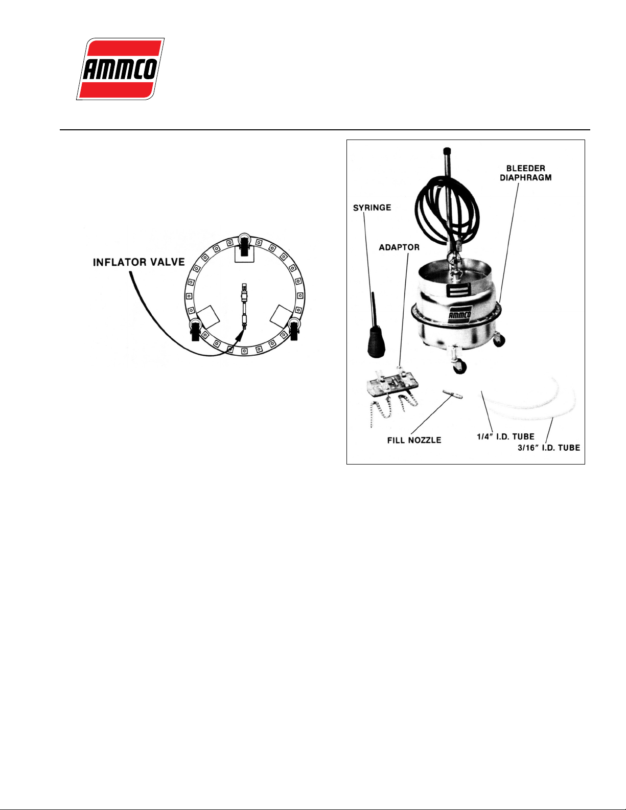
Filling And Charging The Bleeder
1. Release the air from the brake bleeder by depress-
ing the inflator valve. Then remove the valve core.
2. Remove the hose assembly from the fill hole on top
of the brake bleeder by loosening the wing nut and turning the lock plate 90˚. Use a clean blunt instrument to
gently push the diaphragm to the bottom of the bleeder
tank.
3. Insert a plastic funnel into the fill hole and add brake
fluid. The funnel will catch the overflow which can be
removed with the suction syringe.
4. Remove the funnel and replace the hose assembly
into the fill hole. Position the lock plate under the lock
tabs and tighten the wing nut.
5. Replace the valve core and tighten. Inflate to 15 PSI.
6. Insert the fill nozzle into the hose coupler, open the
shutoff valve and bleed the brake fluid into a cup until the
flow is free of bubbles. Add air to bring the bleeder’s
pressure back up to 15 P.S.I.
CAUTION: FOR SAFE OPERATION DO NOT
INFLATE TO MORE THAN 15 P.S.I.
Bleeding The Brakes
1. Pressurize the brake bleeder to not more than
15 P.S.I. Bleeding at this low pressure should not
cause the metering valve to close.
2. Use fender covers to protect paint from any acci-
dental brake fluid spills. If brake fluid is dripped on a
painted surface, immediately flush the area with water.
DO NOT try to wipe the brake fluid from the paint!
3. Remove the master cylinder cover. Refold the rub-
ber cover gasket if necessary.
4. Carefully wipe any grit from the upper perimeter of
the master cylinder reservoir.
5. Install the appropriate bleeder adapter on the mas-
ter cylinder. DO NOT pinch any brake lines or electrical
wires with the hold-down chains.
CAUTION: Plastic
reservoirs may break if the adapter’s chains are overtightened. The chains should only be tight enough to seal
the adapter on the master cylinder.
6. Connect the bleeder’s quick coupler to the adapter.
Model 7300 High Bleeder
Operating Instructions with Parts Identification
AMMCO, Inc. • Hennessy Industries • 1601 J.P. Hennessy Drive, LaVergne, TN 37086-3565
(800) 688-6359 • (615) 641-7533 • (615) 641-5104 FAX • www.ammcoats.com
922039 07 04/08 1 of 2 © COPYRIGHT 1993 HENNESSY INDUSTRIES AND AMMCO ALL RIGHTS RESERVED PRINTED IN U.S.A.
Page 2
7. Push one of the plastic tubes onto a front bleeder.
Put the loose end of the tube into the plastic cup to catch
the brake fluid. Open the bleeder.
8. Bleed one front caliper until the brake fluid dis-
charge changes color, then close the bleeder.
9. Bleed the other front caliper in the same manner as
outlined in steps 7 and 8 above.
10. Attach the hose to the bleeder with the loose end
in a cup before opening each rear bleeder. Allow the
brake fluid to bleed until it changes color, then close the
bleeders. Bleeding the system until the brake fluid
changes color flushes contaminants and air, trapped
between the old and the new fluid, from the system.
STEPS 11 & 12 DO NOT APPLY TO 4-DRUM BRAKE VEHICLES
11. Use slow, short strokes (approximately 2" travel)
of the brake pedal to adjust the front pistons and pads
out to the rotors. DO NOT overstroke the master cylinder
by pushing the brake pedal to the floor. Overstroking the
master cylinder may damage it’s sealing cups.
12. Rebleed all disc brake calipers to remove air that
may have been trapped between the piston and the
caliper.
13. CAUTION: The quick coupler will squirt brake
fluid when it is removed from the adapter. Before disconnecting, wrap a shop cloth around the quick coupler
to absorb the brake fluid. Remove the adapter.
14. Attach the fill nozzle to the bleeder’s hose. Press
the fill nozzle against the side of the reservoir about 3/8"
down from the top to fill the reservoir to about 1/4" from
the top.
15. Replace the master cylinder cover.
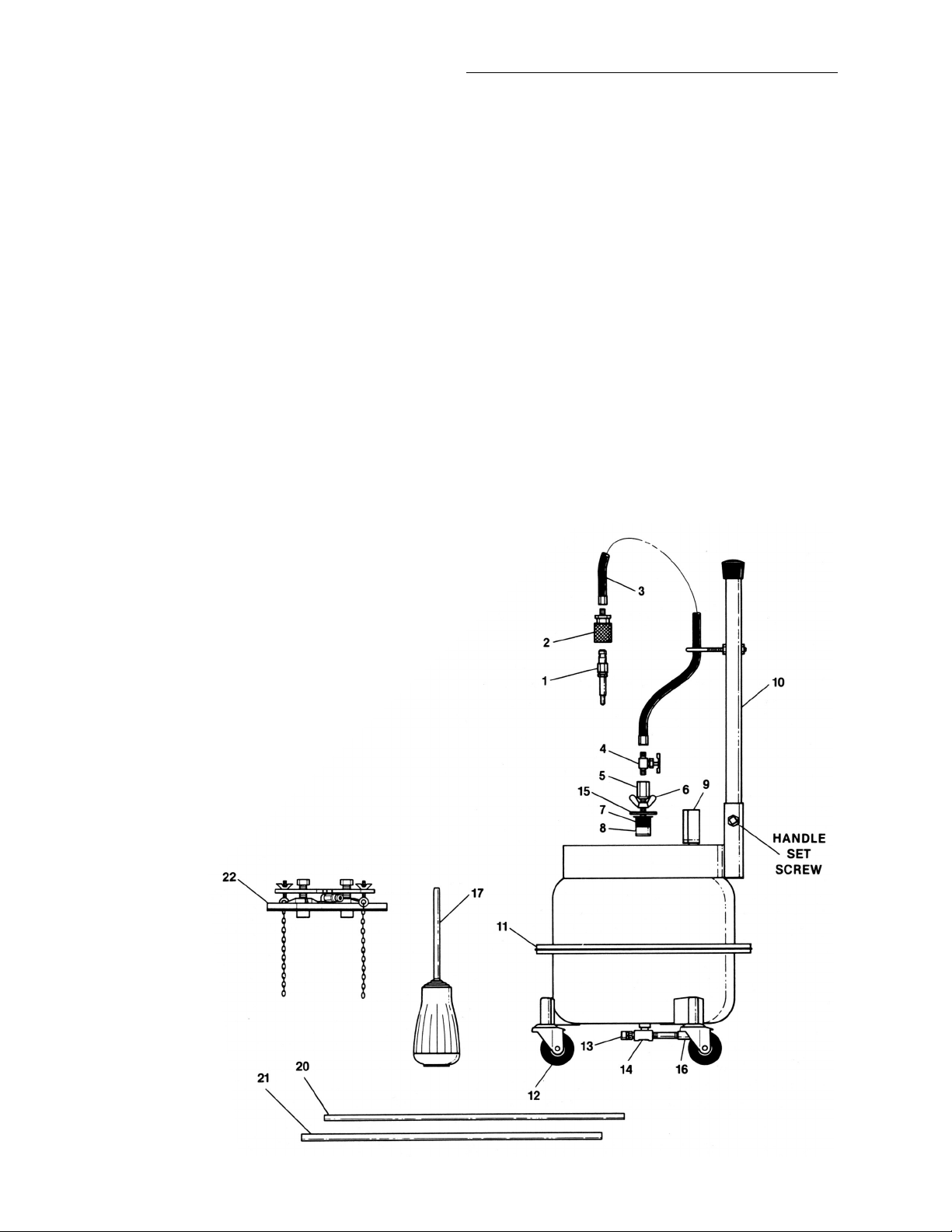
Item Part No. Qty. Description
1 922059 1 Nozzle Fill
2 922047 1 Coupler, Quick
3 922043 1 Hose, Pressure
4 922044 1 Valve, Shutoff
5 922054 1 Tube, Fill Plug Core
6 922055 1 Nut, Fill Plug Wing
7 922046 1 Plug, Fill
8 922056 1 Nut, Fill Plug Seal
9 925662 1 Gauge, Pressure
10 922048 1 Handle Assembly
11 922050 1 Diaphragm, Bleeder
12 922049 1 Wheel, Swivel
13 922045 1 Valve, Safety
14 922053 1 Fitting, “T”
15 922052 1 Washer, Fill Plug
16 922051 1 Body, Air Release Valve
17 922057 1 Syringe
20 922339 1 Tube, 1/4" I.D.
21 922338 1 Tube, 3/16" I.D.
22 907330 1 Adapter
922039 07 04/08 2 of 2 © COPYRIGHT 1993 HENNESSY INDUSTRIES AND AMMCO ALL RIGHTS RESERVED PRINTED IN U.S.A.
 Loading...