

Page 1
1601 J. P. Hennessy Drive, LaVergne, TN USA 37086-3565 615/641-7533 800/688-6359 Manual Part No.: 910369 02
HENNESSY INDUSTRIES INC. Manufacturer of AMMCO
®
, COATS®and BADA®Automotive Service Equipment and Tools. Revision: 06/01
Installation Instructions
Operating Instructions
Safety Instructions
Maintenance Instructions
READ these instructions before placing unit in
service. KEEP these and other materials delivered
with the unit in a binder near the machine for
ease of reference by supervisors and operators.
7000
Disc Rotor Lathe
®
Page 2

ii • AMMCO 7000 Brake Lathes
Brake Lathes
Page 3

AMMCO 7000 Brake Lathes • iii
Table of Contents
Safety Notices and Decals . . . . . . . . . . . . .iv
Warning . . . . . . . . . . . . . . . . . . . . . . . . . . . .iv
Cautions and Dangers . . . . . . . . . . . . . . . . . . . .iv
Owner’s Responsibility . . . . . . . . . . . . . . . .v
Definitions of Hazard Levels . . . . . . . . . . . .v
Important Safety Instructions . . . . . . . . . .vi
Installation
Receiving . . . . . . . . . . . . . . . . . . . . . . . . . . . . . .1
Wiring Requirements . . . . . . . . . . . . . . . . . . . . .1
Installation . . . . . . . . . . . . . . . . . . . . . . . . . . . . .1
Lathe Operation
Operating Specifications . . . . . . . . . . . . . . . . . . .2
Lathe Components . . . . . . . . . . . . . . . . . . . . . . .3
Arbor Installation . . . . . . . . . . . . . . . . . . . . . . . . .4
Adapters . . . . . . . . . . . . . . . . . . . . . . . . . . . . . . .4
Basic Operation . . . . . . . . . . . . . . . . . . . . . . . . . .4
Adjustments . . . . . . . . . . . . . . . . . . . . . . . . .4 - 5
Reconditioning Disc Brake Rotors . . . . . . . . . . . .6
Rotor Mounting . . . . . . . . . . . . . . . . . . . . . . . . . .6
Reconditioning Disc Brake Rotors—Set-Up . . .7 - 9
Machining . . . . . . . . . . . . . . . . . . . . . . . . . . . . .10
Typical Rotor Mounting Configurations . . . . . . . .11
Maintenance and Service
Oiling . . . . . . . . . . . . . . . . . . . . . . . . . . . . . . . .12
Cleaning . . . . . . . . . . . . . . . . . . . . . . . . . . . . . .12
Care of Arbors and Adapters . . . . . . . . . . . . . . .13
Contents
Page 4
iv • AMMCO 7000 Brake Lathes
Safety
Safety Notices and
Decals
For your safety, and the safety of others, read and
understand all of the safety notices and decals included here and on the unit.
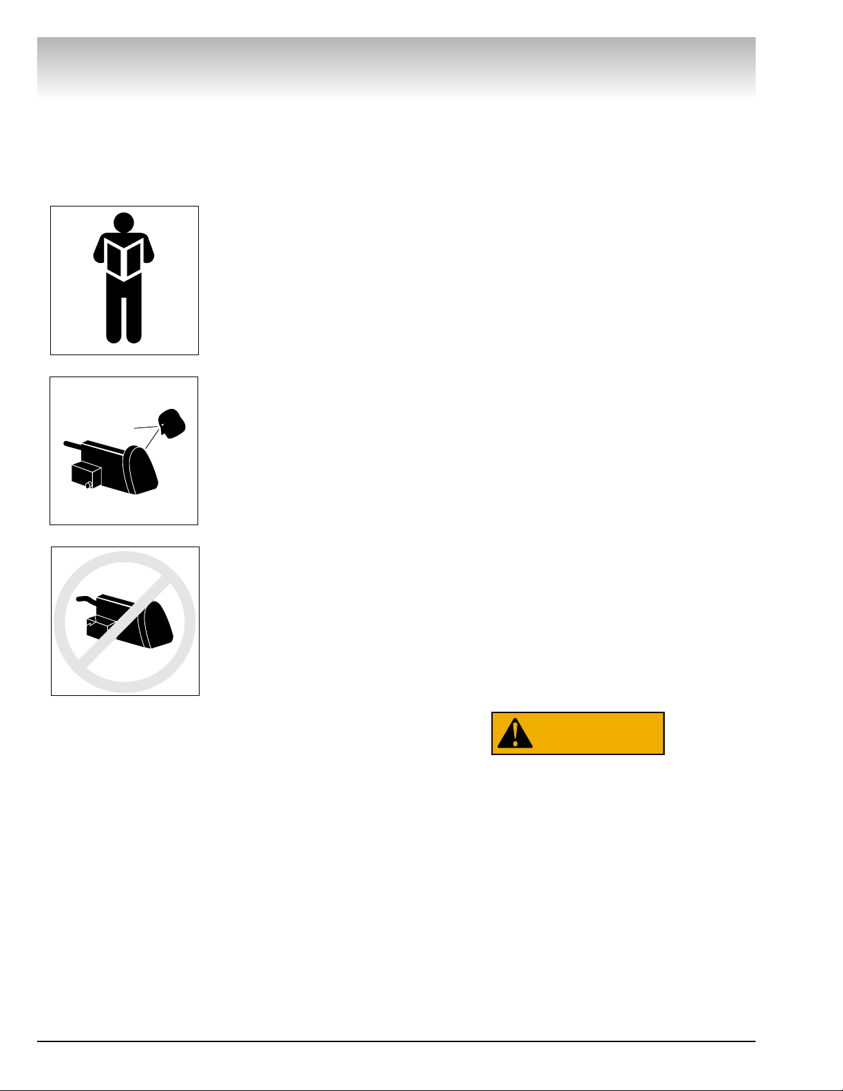
Read entire manual
before installing,
operating, or servicing this equipment.
Proper maintenance
and inspection is
necessary for safe
operation.
Do not operate a
damaged lathe.
Warning
This equipment incorporates parts such as snap
switches and power receptacles which tend to produce arcs or sparks. Theref ore, when located in a service facility, the unit should be in a room or enclosure
provided for the purpose, or should be at least 18” or
more above floor to minimize the risk of igniting fuel
vapors.
Cautions and Dangers
1. Eye and face protection requirements:
“Protective eye and face equipment is required
to be used where there is a reasonable
probability of injury that can be prevented by use
of such equipment.” OSHA 1910.133 (a).
Protective goggles, safety glasses, or a face
shield must be provided by the purchaser/user
and worn by the operator of the equipment.
Make sure all eye and face safety precautions are
followed by the operator(s). Keep bystanders out
of the area.
2. Do not remove any safety equipment, belt
guards, or shortcut controls or operations.
3. Make sure drums and rotors are properly and
squarely mounted before starting lathe, and that
all parts are secure.
4. Do not wear loose clothing, jewelry, or gloves
when operating or working around a lathe.
5. Do not overload the lathe. Read and understand
the lathe specifications. Overloading is poor
machine tool practice, shortens the life of the
lathe, and could cause a failure resulting in
personal injury.
Failure to follow danger, warning, and caution
instructions may lead to serious personal injury or
death to operator or bystander or damage to property. Do not operate this machine until you read
and understand all the dangers, warnings and cautions in this manual. For additional copies of either,
or further information, contact:
Hennessy Industries, Inc.
1601 J.P. Hennessy Drive
LaVergne, TN 37086-3565
(615) 641-7533 or (800) 688-6359
www.Hennessy-Ind.com
WARNING
Page 5
AMMCO 7000 Brake Lathes • v
Owner’s Responsibility
To maintain machine and user safety, the responsibility of the owner is to read and follow these instructions:
• Follow all installation instructions.
• Make sure installation conforms to all applicable
Local, State, and Federal Codes, Rules, and
Regulations; such as State and Federal OSHA
Regulations and Electrical Codes.
• Carefully check the unit for correct initial function.
• Read and follow the safety instructions. Keep
them readily available for machine operators.
• Make certain all operators are properly trained,
know how to safely and correctly operate the
unit, and are properly supervised.
• Allow unit operation only with all parts in place
and operating safely.
• Carefully inspect the unit on a regular basis and
perform all maintenance as required.
• Service and maintain the unit only with
authorized or approved replacement parts.
• Keep all instructions permanently with the unit
and all decals/labels/notices on the unit clean and
visible.
• Do not override safety features.
Definitions of Hazard
Levels
Identify the hazard levels used in this manual with
the following definitions and signal words:
DANGER
Watch for this symbol:
It Means: Immediate hazards, which will result in
severe personal injury or death.
WARNING
Watch for this symbol:
It Means: Hazards or unsafe practices, which could
result in severe personal injury or death.
CAUTION
Watch for this symbol:
It Means: Hazards or unsafe practices, which may
result in minor personal injury or product or property
damage.
Watch for this symbol! It means BE ALERT! Your
safety, or the safety of others, is involved!
Safety
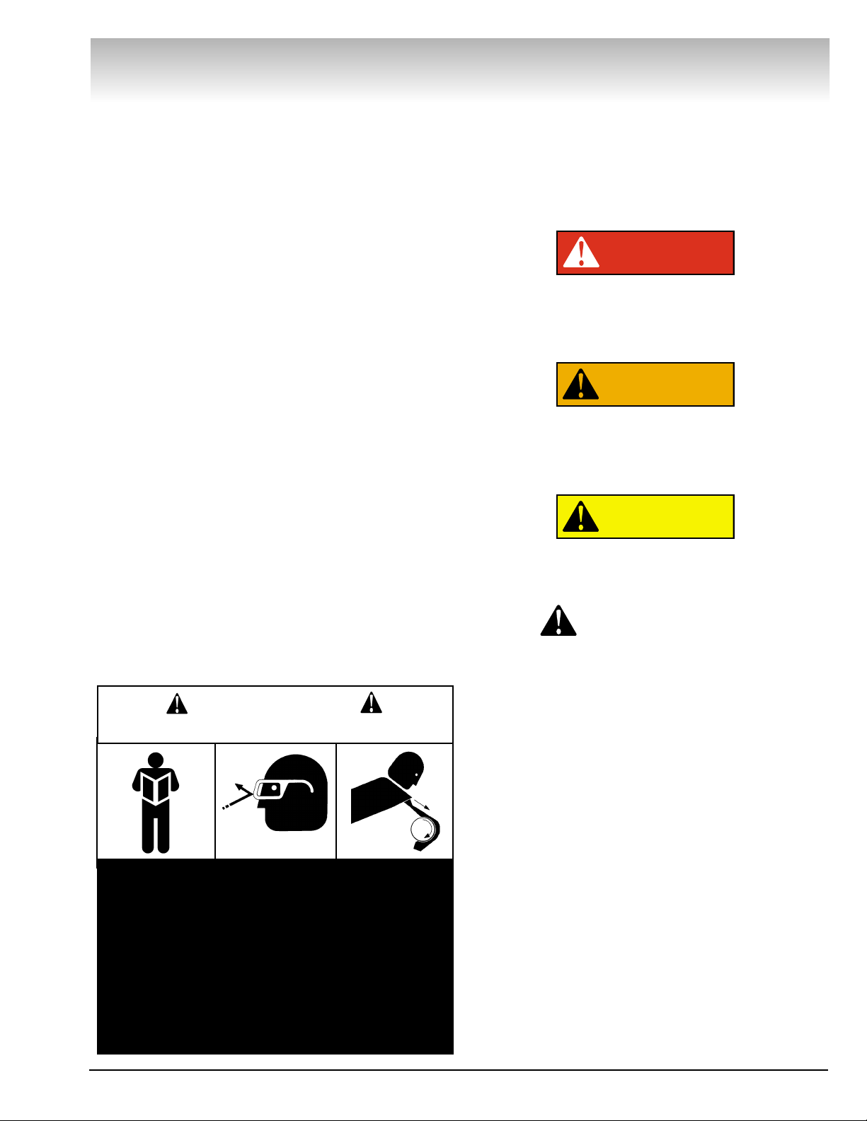
1. Read and follow instructions.
2. Always wear eye protection, avoid loose
clothing and jewelry.
3. Keep all guards, shields, and covers in place and
in working order.
4. Keep bystanders out of work area.
5. Unplug unit from power source before servicing
or adjusting.
6. Maintain unit properly, keep work surfaces and
work area clean.
CAUTION
Prevent accidents and injury, read and follow instructions.
DANGER
WARNING
CAUTION
Page 6

vi • AMMCO 7000 Brake Lathes
READ ALL INSTRUCTIONS
When using your garage equipment, basic safety precautions should always be followed, including the following:
1. Keep guards in place and in working order.
2. Remove adjusting keys and wrenches from the tool
before turning it on. Make this a habit.
3. Keep work area clean and well lighted. Cluttered
areas and benches invite accidents.
4.To reduce the risk of fire, do not operate equipment
in the vicinity of open containers of flammable liquids
(gasoline).
5. Adequate ventilation should be provided when w orking on operating internal combustion engines.
6. Care must be taken as burns can occur from touching hot parts.
7. Do not operate equipment with a damaged cord or
if the equipment has been dropped or damaged—until it
has been examined by a qualified serviceman.
8. If an extension cord is necessary, a cord with a current rating equal to or more than that of the equipment
should be used. Cords rated for less current than the
equipment may overheat. Care should be taken to
arrange the cord so that it will not be tripped over or
pulled.
9. To reduce the risk of electric shock, do not use on
wet surfaces or expose to rain.
10. Keep children away. All bystanders should be kept
completely away from the work area.
11. Make the workshop kid-proof. Use padlocks and
master switches, and remove starter keys.
12. Don’t f orce a tool. It will do the job better and safer
at the rate for which it was designed.
13. Use the right tool. Don’t force a tool or an attachment to do a job for which it was not designed.
14. Dress properly. Keep hair, loose clothing, neckties,
shop rags, jewelry, fingers, and all parts of body away
from moving parts. Non-slip footwear is recommended.
15. ALWAYS WEAR SAFETY GLASSES. Everyday eyeglasses only have impact resistant lenses, they are NOT
safety glasses. Safety glasses, goggles, or a face shield
will help protect the operator from injury. Use a face
shield and dust mask during dusty operations.
16. Secure the work properly to the unit for setup and
tool bit positioning. Do not attempt to hold a drum or
rotor steady on the arbor with your hands. Both hands
must be free to operate unit.
17. Don’t overreach. Keep proper footing and balance
at all times when lathe is in operation or when working
around the unit.
18. Maintain tools with care. Keep tools sharp and
clean for best and safest performance. Follow instructions for lubricating and changing accessories.
19. Remove power from the unit and disconnect tools
before servicing and when changing accessories such as
blades, bits, cutters, etc. Follow lock-out and tag-out procedures as required.
20. Avoid unintentional starting. Make sure the switch
is in the OFF (O) position before plugging the machine in
or performing any maintenance or service work.
21. Use of improper accessories may cause risk of
injury to operator or bystanders. Use only as described in
this manual. Use only manufacturer’s recommended
attachments.
22. Never stand or lean on a lathe. Serious injury could
occur if the lathe is tipped or if the cutting tool is unintentionally contacted.
23. Check damaged parts carefully. Before further use
of the lathe, a guard or other part that is damaged should
be carefully checked. Immediately replace all damaged,
missing, or non-functional parts. Check for alignment of
moving parts, binding of moving parts, breakage of parts,
mounting, and any other conditions that may affect operation. Guards and other parts that are damaged should be
properly repaired or replaced before lathe is used again.
24. A lways feed the work into a blade or cutter and
against the direction of rotation. Cutters and tool bits are
designed to cut from the inside of a drum or rotor to the
outer edge. Do not attempt to cut from the outside edge
in to the center.
25. Never leave tools running unattended. Turn the
power off. Don’t leave the tool until it comes to a complete stop.
26. Never use compressed air to blow the tool clean.
Chips and dust may be driven between machined parts
and into bearings, causing undue wear. They may also
contact persons in the area causing personal injury.
Before operating the lathe, review the warning information on the lathe and the cautions, warnings and dangers in
this manual. Also review the following general safety instructions. Failure to follow safety instructions could result in
personal injury to operator or bystanders and damage to the lathe or personal property.
IMPORTANT SAFETY INSTRUCTIONS
SAVE THESE INSTRUCTIONS
Page 7

AMMCO 7000 Brake Lathes • 1
Installation
Receiving
The shipment should be thoroughly inspected as
soon as it is received. The signed bill of lading is
ackno wledgement b y the car rier of receipt in good condition of shipment covered by our invoice.
If any of the goods called for on this bill of lading are
shorted or damaged, do not accept them until the carrier makes a notation on the freight bill of the shorted
or damaged goods. Do this for your own protection.
NOTIFY THE CARRIER AT ONCE if any hidden loss or
damage is discovered after receipt and request the carrier to make an inspection. If the carrier will not do so,
prepare a signed statement to the effect that you have
notified the carrier (on a specific date) and that the carrier has failed to comply with your request.
IT IS DIFFICULT TO COLLECT FOR LOSS OR DAMAGE AFTER YOU HAVE GIVEN THE CARRIER A CLEAR
RECEIPT.
File your claim with the carrier promptly. Support your
claim with copies of the bill of lading, freight bill,
invoice, and photographs, if available.
Although AMMCO’s responsibilit y ceases upon delivery of the shipment to the carrier, we will gladly assist
in tracing lost shipments. Our willingness to assist in
every possible manner does not make AMMCO
responsible for collection of claims or replacement of
lost or damaged materials. Shipping damage claims will
not be handled under warranty.
Wiring Requirements
Grounding: This lathe should be electrically grounded
to protect the operator from shock.
Cord-connected Lathes: The lathe is equipped with an
approved 3-conductor cord and a 3-prong grounding
type plug to fit the proper grounding type receptacle. If
your lathe is for use on 115 volts, it has a plug as illustrated in Fig. A1. If used on 220 volts it will have a plug
as shown in Fig. A2.
Use only 3-wire extension cords which have 3-prong
grounding type plugs and 3-pole receptacles which
accept the lathe’s plug.
Replace or repair damaged or worn cords immediately
AMMCO electrical and electronic based machines are
designed for nominal line voltages with variations of
ten percent (10%) around the nominal, i.e.; 115 volt
input could vary from 103 volts on the low side to 127
volts on the high side. These percentages also apply to
220 VAC, 480 VAC based products, etc.
Any line voltage lower or higher than ten percent
(10%) of nominal will cause problems with the
machine. If the machine receives below or above the
design limit, erratic operation will ensue with a degradation in component reliability and life. By law the
power company must supply power within the ten percent (1 0%) limit of nominal line. It is up to the customer
to see that his facility is properly wired and is supplying
power to the machine within its design limits.
Inadequate voltages and wiring will only produce problems.
Installation
Set-Up - If you ordered a brake benc h with your lathe,
use the assembly instructions supplied with it. After
assembly, the bench should be leveled and bolted
down with 3/8" or 7/16" bolts or lag screws. Clean the
lathe accessories with solvent, install mounting hooks
and hang the items on the accessory storage board.
Note: A light film of oil should be put on all adapters
to protect the machined surf aces from r ust, refer to the
CARE OF ARBORS AND ADAPTERS section for complete care.
Installing the lathe - Unbolt the lathe from the shipping pallet and place it on the bench. Bolt the lathe to
the bench with the hardware provided. Make sure the
motor switch is OFF before plugging the machine in.
Lubrication - Remove the shipping plug and insert
the oil dip stick, and check oil level, Fig. A3. The lathe is
shipped from the factory with the correct amount and
type of oil. Refill as necessary with EP-80-90 gear oil
and check the oil level often.
Brake Lathes
Figure A3
Figure A2Figure A1
Page 8

2 • AMMCO 7000 Brake Lathes
Brake Lathes
Lathe Operation
Operating Specifications
Cross Feed Speed Infinitely Variable
0.002 in./rev. to 0.006 in./rev.
(0.051 to 0.152 mm)
Spindle Speeds:
Pulley: Inner Groove 100 RPM
Middle Groove 150 RPM
Outer Groove 200 RPM
Spindle Diameter 2-718" (73.02 mm)
Capacities:
Maximum Brake Rotor Diameter (3/8" Thick Rotor) 19-3/4"
Maximum Brake Rotor Diameter (1-3/4" Thick Rotor) 20-1/2"
Maximum Rotor Thickness 1-3/4" (44.45 mm)
Maximum Arbor Load
1 Inch Standard Arbor 100 lbs. (45.4 kg.)
1.875 Inch Optional Arbor 200 lbs. (90.7 kg.)
Shipping Weight
(Lathe Only)
315 lbs. (143 kg.)
Electrical Requirements 115 VAC, 60 Hz, I Ph, 14 amp - standard
220 VAC, 60 Hz, I Ph, 7 amp - optional
(Unless Otherwise Specified)
Floor Space Requirements 48 in. wide x 34-3/4 in. deep
(When Mounted On Optional Bench) (1219.20 mm x 882.65 mm)
Page 9

Brake Lathes
AMMCO 7000 Brake Lathes • 3
Lathe Components
Page 10

Arbor Installation
The 1" arbor shipped with the lathe has been carefully matc hed
to the lathe during final assembly and testing. Witness marks
have been etc hed onto the arbor and spindle f or repeatable, precise alignment.
The witness marks should be carefully aligned when installing
the arbor, Fig. B 1. A true running arbor is essential to professional quality rotor reconditioning.
The drawbar, whic h can be tightened or loosened at the rear of
the spindle, pulls the hardened and ground tapers of the arbor
into the matching seats.
Adapters
Although the adapters, arbor, and spindle are made
of top grade steel and are turned,hardened, and precision ground to close tolerances, great care should
be taken in their use, handling, and storage. Even
the smallest nick, scratch or loose chip on the mating machined surfaces, Fig. B 2, can cause incorrect
rotor mounting alignment.This will cause inaccurate
machining.
Note: A light film of oil should be put on all adapters to protect
the machined surfaces from rust. Always inspect the surface,
the face and the seating tapers of each part. Wipe each part
clean before and after using it. Carefully correct any flaw with a
fine stone. If damage cannot be corrected, replace the part.
Basic Operation
To completely understand rotor turning you must have a
knowledge of the lathe itself.
The spindle is a motor driven shaft that turns the arbor on
which the brak e rotor is mounted. By turning the rotor and holding a cutting tool to the rotor, metal can be removed.
By operating the cross feed lever the cutting tool is automatically drawn across the rotor brake face as the cross feed moves
away from the tool while the rotor turns. Cross feed may also
be done manually using the cross feed handwheel.
Do not try to move any feed levers or dials without
the drive motor running. Damage may occur to the
gear trains.
Adjustments
Spindle Speed - Release the belt tension by moving the V-belt
adjusting lever clockwise, Fig. B 3. Move the belt to the pulley
groove that will give the correct spindle speed for the cut to be
taken, Fig. B 4.
Brake Lathes
4 • AMMCO 7000 Brake Lathes
Figure B1
Figure B2
Figure B3
Figure B4
CAUTION
CAUTION
Page 11

Cross Feed - The cross feed draws the twin tool bits across the
face of a brake rotor when the cross feed drive is engaged. The
cross also be operated manually using the cross feed handwheel.
Feed Speed - F eed speed refers to the number of thousandths
of an inch the cutting tools move across the f ace of the rotor per
revolution of the spindle. The cross feed speed control adjusts
the feed rate from .002" (.05 mm) to .004" (.1 0 mm) to .006" (.15
mm) per spindle revolution.
V-B elt T ension - When properly adjusted, the V -Belt should ha ve
1/4" - 1/2" of slack. To adjust the tension, loosen the tension
adjusting nut so the weight of the motor pulls the V-Belt snug
and rotate red knob to its furthest counterclockwise position.
Push the belt in 1/4" - 1/2" on one side and tighten the nut, Fig.
B 5.
Cross Feed Leg Tension -- Be sure the brass plug and spring
are under the allen screw. (if the cross feed has been pulled out
beyond the end of the guide bar, the plug and spring may have
been lost.) Replace the plug and spring, Fig. B 6, then snug the
allen screw all the way down then back it off 1/8" of a turn.
Tool-Bit Holder Adjustment (Preliminary Cleaning) - Refer to
parts identification manual for nomenclature.
Before adjusting the tool-bit holders on a used twin cutter, the
following steps should be performed.
1. Be sure the tool-bit holder bores in the twin cutter body are
clean along with the tool-bit holders and tool-bit assemblies.
2. Replace the brass plugs if the original plugs are “mush-
roomed” or worn.
3. Clean the threads of the lock knob holes by running a tap
through them.
(Adjusting Tool-Bit) - Refer to parts identification manual for
nomenclature.
1. Loosen and back off the hex nut locking the locating screw
in position.
2. Loosen and back off the lock knob.
3. Firmly tighten the locating screw to align the tool-bit holder
by its locating groove.
4. Simultaneously loosen the locating screw and tighten the
tool-bit holder lock knob until the locating scre w is loose and the
lock knob is tight.
5. Screw the locating screw in until it is snug, then back it off
1/8 to 1/4 of a turn.
6. Hold the locating screw in this position and tighten the hex
nut to lock the screw in place.
7.Turn the outer knurl of the twin cutter control left and right
to check for a smooth, free movement. Repeat the procedure
for the other tool-bit holder.
Brake Lathes
AMMCO 7000 Brake Lathes • 5
Figure B5
Figure B6
Page 12

Reconditioning Disc Brake Rotors
Each brake disc should be carefully inspected for SCORING,
RUST RIDGES (at the inner and outer circumference of the
rotor), and HARD SPOTS. Any excessive wear or deformity
should be noted and, if not within acceptable limits, the rotor
should be replaced. Use a micrometer to check the thickness of
the rotor at no less than three points around the circumference
about 1" (25.4 mm) in from the outer diameter, Fig. B 7. If the
rotor thickness v aries between readings, it should be machined;
however, if the thickness is less than the minimum established
by the car manufacturer (or if it will be less after reconditioning),
the rotor should be replaced.
Note: Most often the discard thickness dimension is cast into
the rotor, not the minimum machine to thickness.
Mount the twin cutter on the cross feed with the stud bolt
extending through the cast slot. In some applications the stud
bolt may have to be positioned in one of the alternate stud
mounting holes, Fig. B 8. To prevent contamination of the gear
box position set screw in unused hole. To secure the twin cutter use the nut and washer assembly and tighten firmly.
Rotor Mounting
Fig. B20, TYPICAL ROTOR MOUNTING CONFIGURATIONS is
a model example of many of the mounting configurations necessary to meet the requirements of brake rotor machining.
Inspect the rotor hub for loose or damaged bearing races and
replace parts as necessary. Hubbed rotors are mounted on the
taper adapters that fit into the bearing races. Hubless rotors use
a cone in the center hole and a hubless adapter on each side of
the rotor. Spacers are used to fill out the arbor shaft so that the
arbor nut can be tightened. The adapters, cones, and spacers
supplied with your lathe will allow you to recondition the majority of rotors on today’s vehicles. Optional adapters, cones, and
spacers are available to meet special needs.
Note: Adapters may also be used as spacers to fill out the
arbor if care is taken to prevent damage to their machined surfaces. The patented self-aligning spacer prevents diagonal thrust
on the adapters. The self-aligning spacer should always be used
adjacent to the arbor nut.
Brake Lathes
6 • AMMCO 7000 Brake Lathes
Figure B7
Figure B8
Page 13

Reconditioning Disc Brake Rotors—Set-Up
1. After the brake rotor is mounted on the arbor, install the
silencer band. This is easily done by stretching the band to its
full length and then wrapping it around the rotor and hooking
the end metal loop over a lead weight, Fig. B 9.
2. Center the twin cutter to the rotor. Loosen the stud nut,
Fig. B 10, and adjust the twin cut ter so that the rotor is centered
between the tool bits. The slot of the twin cutter should be
approximately parallel to the lathe spindle. Tighten the stud nut
firmly.
3. Install the safety shield. Review the CAUTIONS / DANGERS and GENERAL SAFETY INSTRUCTIONS. The safety
shield is easily screwed onto the twin cutter in the threaded
mounting hole provided, Fig. B 11. Also always wear safety
glasses or a face shield. Cutting or grinding on an exposed surface such as a rotor will produce flying chips.
Brake Lathes
AMMCO 7000 Brake Lathes • 7
Figure B9
Figure B10
Figure B11
Page 14

4. Adjust the drive belt to match the rotor size. Use the outer
pulley groove for all passenger car and light truck rotors, Fig. B
12. Choose one of the inner grooves when machining medium
duty truck rotors.
5. Make sure that the tool bits clear the rotor faces and the
silencer band. Give the rotor a full turn by hand and start the
lathe.
6. Turn each tool bit control (the outer knurled knobs) clockwise until the tool bits just contact the rotor faces. When the
tool bits have made contact, rotate each of the inner depth-ofcut collars to zero and back the tool bits away from the rotor.
From this point on all tool adjustments will be made with the
tool bit controls, Fig. B 13. The inner depth-of-cut collars will be
the reference and should not be moved.
7.Turn the cross feed handwheel until the tool bits are at midpoint of the rotor face. Turn the left hand tool bit control until the
tool bit contacts the rotor surface and makes a scratch cut no
deeper than .001", Fig. B 14.
Brake Lathes
8 • AMMCO 7000 Brake Lathes
Figure B14
Figure B12
Figure B13
Page 15

The scratch will usually appear as an incomplete circle. This is
caused by runout or wobble due to rotor condition or b y the w a y
the rotor is mounted on the arbor.
To check that the rotor is correctly mounted, loosen the arbor
nut and turn the rotor 180° by hand, (make sure the inside
adapter does not rotate along with the rotor), Fig. B 15.
Retighten the arbor nut. Turn the cross feed handwheel back
about a half turn, start the lathe and move the tool bit in to make
a second scratch cut. Stop the lathe.
If the scratch cuts are side by side, Fig. B 16, next page, the
runout or wobble is caused by the rotor condition. A dial indicator may be used to compare rotor runout with manufacturer’s
specifications.
If the scratch cuts are opposite one another (180°), Fig. B 17,
the rotor may not be properly mounted on the arbor. Remove
the rotor from the arbor . Examine each adapter and the arbor for
nicks, burrs, chips, dirt, and rust. Also inspect the rotor hub for
loose or damaged bearing cups. Clean, repair, remount, or
replace as necessary.
Brake Lathes
AMMCO 7000 Brake Lathes • 9
Figure B15
Figure B16
Figure B17
Page 16

Machining
8. Recheck the setting of the depth-of-cut collars which were
on zero. Move the tool bits inward until they just contact the
faces of the rotor. Reset the collars if necessary.
9.Turn the cross feed handwheel clockwise until the tool bits
are near the rotor hub, Fig. B 18. Start the lathe. Turn both tool
bit controls to the desired depth-of-cut and lock them in position.
Note: Either rough or finish cuts may be taken to resurface a
rotor. Generally, finish cuts should be .004" (.10 mm) to .006"
(.15 mm). Very shallow cuts [less than .004" (.10 mm)] tend to
reduce tool bit life because heat won’t transfer to the rotor efficiently.
Move the cross f eed speed control knob to the fast position f or
roughing cuts.
10. Now engage the automatic cross feed (by moving the
knob), Fig. 19. When the cross feed has mo v ed the cutting tools
all the way across the face of the rotor, the feed will shut off
automatically.
Brake Lathes
10 • AMMCO 7000 Brake Lathes
Figure B18
Figure B19
Page 17

AMMCO 7000 Brake Lathes • 11
Typical Rotor Mounting Configurations
Brake Lathes
Figure B20
A 1" Arbor
B Arbor Nut
C Self-Aligning Spacer
D Spring
E Large Diameter Hubless Adapter
F Aligning Cup
G Centering Cone
H Tapered Cone Adapter
I Adapter Being Used As Spacer
J Tapered Cone Adapter
K Spacer
L Small Diameter Hubless Adapter
Page 18

Maintenance and Service
Note: Refer to LATHE COMPONENTS.
Oiling
The lathe is shipped from the factory with the correct amount
and type of oil. Refill as necessary with EP-80-90 gear oil and
check the oil level often., Fig. C 1.
Every 500 hours drain the oil and refill to the dipstick level with
clean EP-80-90 gear oil. To drain the oil, remove the socket head
drain plug located on the front of the lathe to the right of the
cross feed assembly, Fig. C 2.
Cross Feed - Once a month pump automotive chassis grease
into the cross feed grease fitting until it begins to come out of
the relief slot at the base of the fitting. CAUTION: Use a HAND
GREASE GUN ONLY, a high pressure gun can burst the lathe
casting, Fig. C 3.
Cleaning
Keep the lathe as clean as possible for trouble free operation
as well as safety and longer lathe life. Use a brush to sweep
metal chips and dust of f the lathe. DO NOT USE COMPRESSED
AIR TO BLOW THE LATHE CLEAN. Chips and dust could be
driven between machined parts and into bearings causing
undue wear.
Brake Lathes
12 • AMMCO 7000 Brake Lathes
Figure C1
Figure C2
Figure C3
Page 19

Care of Arbors and Adapters
Although the adapters, arbors, and the spindle are
made of top grade steel and are turned, hardened,
and precision ground to close tolerances, great care
should be taken in their use, handling, and storage.
Even the smallest nick, scratch, or loose chip can
cause incorrect rotor alignment, resulting in inaccurate machining.
Remove all adapters from the arbor after mac hining a rotor and
wipe them clean - especially the inboard adapter. When a finished rotor is removed from the arbor, the inboard adapter may
move slightly away from the face of the arbor and allow metal
chips to fall into the opening causing a poor mounting for the
next rotor.
Regularly inspect the faces and seating tapers of the adapters
for nic ks and scratches, correct any flaw with a fine stone. If the
damage cannot be corrected, replace the adapter. Handle the
adapters and arbors with care and store them on individual
hooks. DO NOT throw them into a box. The adapters are
designed for mounting rotors only, DO NOT misuse the
adapters.
Brake Lathes
AMMCO 7000 Brake Lathes • 13
CAUTION
Page 20

910369 02 06/01 © Copyright 1989 Hennessy Industries and AMMCO All Rights Reserved Printed in USA
 Loading...