

Page 1
6950
AMMCO
Twin Cutter Tool
Installation and
Operation Instructions
with Cleaning and Adjustment
Procedures and Parts Identification
28723 3/96
P.O. Box 3002, 1601 J.P. Hennessy Drive, LaVergne, TN 37086 615/641-7533 800/688-6359
HENNESSY INDUSTRIES, INC. Manufacturer of AMMCO
®
, COATS®, and BADA®Automotive Service Equipment and Tools
Page 2
2 • 6950 Twin Cutter Tool
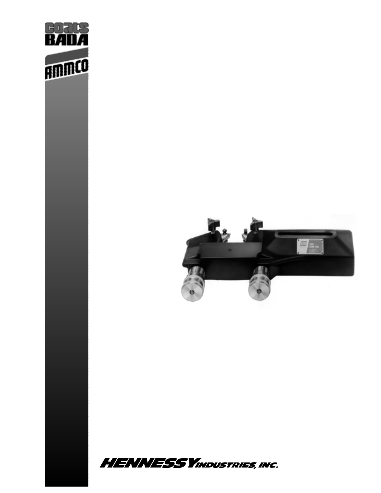
The 6950 Twin Cutter Tool mounts on the lathe in
place of the boring bar. It resurfaces both faces of
a brake rotor simultaneously. Each tool holder is
individually adjustable (in thousandths of an inch
or millimeters) to facilitate precise depth-of-cut
settings (Figure 1).
Figure 1 – Depth-of-cut adjustment knobs
Installation
1. Remove the nut and self-aligning washers
from the boring bar mount on the lathe.
2. Lift off the upper and lower clamp and
remove the boring bar (on models 4000 and
4100 only). Only the stud remains.
Figure 2 – Lathe set up for drum turning
3. Place the twin cutter on the stud.
4. Place the self-aligning washers on the stud,
followed by the nut. Hand tighten the nut.
Figure 3 – Remove boring bar and install twin cutter
5. Visually align the slot in the top of the twin
cutter so it is parallel to the lathe arbor.
Operation
A brake rotor is machined from its center
outward, cutting both faces at the same time.
1. Measure the rotor thickness with a
micrometer and determine the depth of cut
necessary to machine both surfaces.
2. Determine the minimum allowable thickness
(cast into the rotor, or from manufacturers
specifications) and do not machine down past
this minimum.
NOTE: When machining single piston or
floating caliper rotors, more metal may be
taken off one face than the other provided the
minimum overall thickness specification is
maintained.
3. Loosen the cross slide lock and turn the
crossfeed handwheel to back the twin cutter
out far enough to clear a mounted rotor.
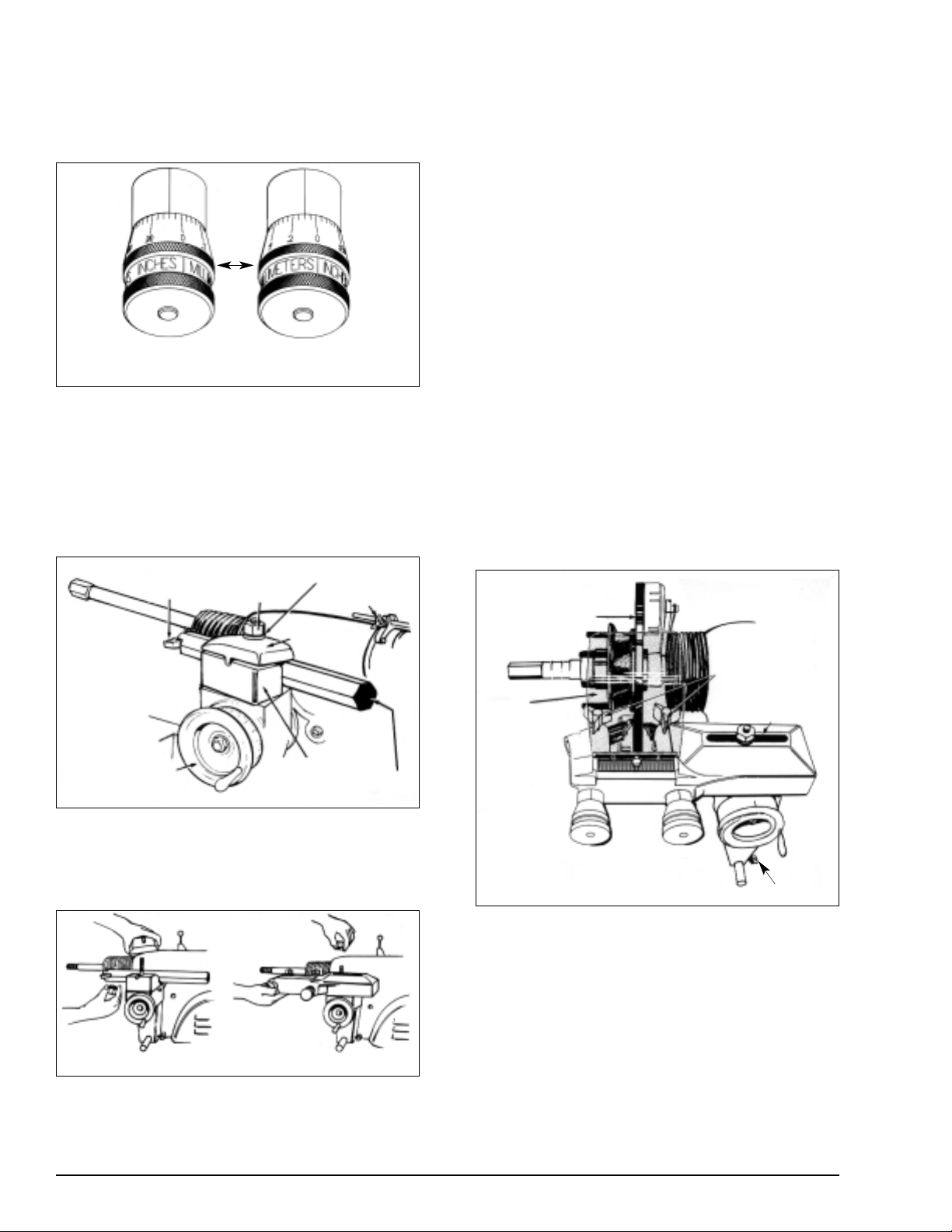
4. Mount the rotor on the lathe arbor using the
appropriate adapters.
NOTE: The mounted rotor illustrated in Figure
4 is a non-vented type. Both vented and nonvented rotors up to 1.75" (44.5 mm) thick may
be resurfaced with the 6950 twin cutter.
Figure 4 – Lathe set up for rotor turning
5. Center the rotor between the tool bits by
positioning the twin cutter to the left or right
along the cast slot (or by adjusting the spindle
feed handwheel).
6. Install a rotor silencer to dampen machining
vibrations.
7. Set the lathe V-belt to the correct groove for
optimum speed and finish. Refer to the lathe
operations manual for proper speeds and
feeds. Generally, slow speeds give a better
finish and longer life.
Dial set to cut 4/1000
of an inch(0.004")
Dial set to cut 1/10
mm (0.1 mm)
Micrometer
Inner
Sleeve
Tool Bit Holder
Nut
Self-Aligning Washers
Crossfeed
Handwheel
Upper Clamp
Lower Clamp
Spindle Lock
Boring Bar
Remove Clamps and Bar
Install Twin Cutter
Rotor
Tool Holder
Lock Knobs
Slot Centers Twin
Cutter to Rotor
Cross Slide
Lock Knob
Safety Shield
Must Be Used
Page 3

6950 Twin Cutter Tool • 3
8. Wrench tighten the stud nut to secure the
twin cutter, then set the lathe spindle lock to
keep the spindle in position.
9. Turn the lathe on.
10. Loosen both tool holder lock knobs on the
twin cutter and turn the depth-of-cut
adjusting knobs until the tool bits just contact
the face of the rotor.
11. Hold the outer end of each knob and turn the
inner micrometer sleeve dial to zero (inch or
metric).
Always use the safety
shield and other
protective eye covering
when machining a disc brake rotor.
12. Turn the crossfeed handwheel to move the
cutting tools into the rotor center.
13. Set the proper depth-of-cut for each tool with
the adjusting knobs and lock the tools.
14. Engage the crossfeed lever and begin the cut.
Depth-of-Cut General Guidelines
Roughing cuts should be no deeper than 0.010"
(0.25 mm) per side.
Finish cuts should be no shallower than 0.002"
(0.05 mm) per side.
Tool Bit Holder Adjustment
Preliminary Cleaning
Before adjusting the tool bit holders on a used
twin cutter, the following steps should be
performed.
1. Be sure the tool bit holder bores in the twin
cutter body, the tool bit holders themselves,
and the tool bit assemblies are clean.
2. Replace the brass gibs if the original gibs are
“mushroomed” or worn.
3. Clean the threads of the lock knob holes by
running a tap through them.
Adjusting
1. Loosen and back off the hex nut locking the
locating screw in position.
2. Loosen and back off the lock screw.
3. Firmly tighten the locating screw to align the
tool bit holder by its locating groove
4. Simultaneously loosen the locating screw
and tighten the tool bit holder lock screw until
the locating screw is loose and the lock screw
is tight.
5. Screw the locating screw in until it is snug,
then back it off 1/8 to 1/4 of a turn.
6. Hold the locating screw in this position and
tighten the hex nut to lock the screw in place.
7. Turn the outer knurl of the twin cutter control
left and right to check for smooth, free
movement.
8. Repeat the procedure for the other tool bit
holder.
CAUTION
Page 4

Parts Identification
ITEM PART NO. QTY. DESCRIPTION
1 6918 * 2 Carbide Insert, Positive Rake
6914 ** 2 Carbide Insert, Negative Rake
2 6499 2 Screw, #4-40 x .25 Oval Head
3 25968 * 1 Holder, Tool Bit, Right Hand, Positive Rake
25969 * 1 Holder, Tool Bit, Left Hand, Positive Rake
10701 ** 1 Holder, Tool Bit, Right Hand, Negative Rake
10702 ** 1 Holder, Tool Bit, Left Hand, Negative Rake
4 9249 2 Screw, Square Head Set
5 10650 1 Tool Holder, Left Hand
10651 1 Tool Holder, Right Hand
6 28584 2 Gib, Brass, Tool Holder
7 6854 1 Screw, Lock
8 28572 1 Twin Cutter Housing
9 6905 1 Spring
10 9879 2 Screw, Locating
11 3528 2 Nut, Hex
12 6977 2 Plug, Dot
13 6109 2 Screw, 3/16-16 Set
14 6908 2 Rod, Dial
15 6906 2 Plug, Dial
16 6929 2 Washer, Spring
17 6907 2 Dial, Micrometer
18 3338 2 Screw, Set
19 6923 2 Knob, Dial Rod
20 6901 1 Dial Assembly
NOTE: These parts ARE NOT
included with the 6950 Twin
Cutter Tool.
For a complete assembly,
order one of the following:
* 28800 Twin Cutter with
Positive Rake Tool
Holders and Bits
** 29800 Twin Cutter with
Negative Rake Tool
Holders and Bits
28723 3/96 © COPYRIGHT 1996 HENNESSY INDUSTRIES AND AMMCO TOOLS ALL RIGHTS RESERVED PRINTED IN U.S.A.
 Loading...